Embed Size (px)
Citation preview

81 - 121
BC HYDRO UNDERTAKING
BC HYDRO REVENUE REQUIREMENT HEARING2004/05 AN D 2005/06
HEARING DATE
May 27 , 2004
TRANSCRIPT REFERENCE
Volume 11 , Page 1613
REQUESTOR: BCUC Counsel
QUESTION
Are there any additional studies besides Black and Veatch?
RESPONSE
Attached is the study comparing design costs for a Qualicum type substationreferred to in section 2. , from which the conclusions in 2. 1 regarding costcomparisons are drawn.

I I I I I I I I I I I I I I 1 R I 1 I
BC Hydro Transmission & Distribution Engineering
Distribution Substation Cost Comparison Study
BC Hydro Black & Veatch Manitoba Hydro
Prepared by:
Walter A. Brunner Robert P. Stewart David H. Thomas
November 200 1

I I I I I I I t I I . i
I
I
. I
i
BC Hydro . T&D Engineering Distribution Substation Cost Comparison Study
Table of Contents
Page
1 .
2 .
3 .
4 .
5 .
Introduction .................................................................................................................... 1
1.1 General ................................................................................................................. 1 1.2 Black & Veatch Participants ................................................................................ 1 1.3 Manitoba Hydro Participants ............................................................................... 1 1.4 BC Hydro Participants ......................................................................................... 1 1.5 Kentucky Power Corporation Participants ........................................................... 1
Substation Single Line ................................................................................................... 2
2.1 2.2
Significant One-Line Changes . Black & Veatch ............................................... 2 Significant One-Line Changes . Manitoba Hydro ............................................... 2
Differences in Approach to the Design . Black & Veatch .......................................... 2
3.1 3.2 3.3 3.4 3.5 3.6 3.7 3.8 3.9
Distribution Fault Levels ...................................................................................... 2 Field Ties for Loads Transfer ............................................................................... 3 Transfer Bus ......................................................................................................... 3 Hook Stick Switches ............................................................................................ 3
Equipment Foundations ........................................................................................ 4 Application of Series Reactors ............................................................................. 4
Reduction in Main Bus Current Carrying Capacity ............................................. 5 138 kV Portion of the Substation ......................................................................... 5 Other Design Matters ........................................................................................... 5
Differences in Approach to the Design . Manitoba Hydro ........................................ 6
4.1 4.2 4.3 4.4
Application of Series Reactors ............................................................................. 6 Use of Transfer Bus .............................................................................................. 6 Equipment Operating Temperatures .................................................................... 6 Equipment Arrangement and Control Building Design ....................................... 6
Comparison of Costs . Black & Veatch ....................................................................... 6
5.1 Substation ............................................................................................................. 7
Equipment and Materials ..................................................................................... 7 5.2 Engineering .......................................................................................................... 7 5.3 5.4 Construction ......................................................................................................... 8
i

BC Hydro - T&D Engineering Distribution Substation Cost Comparison Study
1. INTRODUCTION
1.1 General
Black & Veatch Corporation (B&V), Manitoba Hydro and East Kentucky Power were invited to participate in a study to compare the costs of developing a medium sized distribution substation. It was proposed that the three groups, together with BC Hydro, prepare a conceptual design and cost estimate based on a One-Line Diagram (with some variations) provided by BC Hydro. The cost estimate is meant to capture all direct costs associated with the project, and be presented in a way that will allow easy comparisons to the other estimates.
Participants were requested to prepare sketches with sufficient detail to clearly show the conceptual design and approach to all systems required in the substation. Each major system should have a cost estimate with quantities, unit prices and total price. In addition, all engineering, design, project management, construction management and construction inspection activities will be estimated primarily upon hours, rather than subjective hourly pricing. The goal being that the estimates can be fairly compared to those of the other groups in this study.
1.2 Black & Veatch Participants
Jim Wardin - Project Executive Orville Finnigan - Project Manager Erik Hale - Project Engineer
1.3 Manitoba Hydro Participants
Gerald Neufeld - Manager, Station Design Department Marianne Goldsborough - Assistant to the Vice President, T&D - Michael Kizuik - Professional Engineer, Station Design Department Rene Doiron - Project Co-ordinator, Station Design Department
1.4 BC Hydro Participants
Walter Brunner - Project Manager Bob Stewart - Manager, Station & Transmission Design David Thomas - Manager, Contract Management
1.5 Kentucky Power Corporation Participants
Mary Jane Warner, P.E. - Manager, Power Delivery Expansion
Citing more pressing priorities Kentucky Power Corporation declined to participate.
1 I

BC Hydro - T&D Engineering Distribution Substation Cost Comparison Study
2. SUBSTATION SINGLE LINE
As a basis for the cost comparison exercise the one-line for the recently completed BC Hydro Qualicum Substation was used (see Appendix 4).
2.1 Significant One-Line Changes - Black & Veatch
The removal of the feeder reactors while increasing the step-down transformer impedance to limit fault currents.
The replacement of the transfer bus with a dual main bus arrangement, plus using field ties as required.
The use of single-phase hook stick operated disconnects switches to isolate the feeder circuit breaker.
The reduction of the main bus current capacity.
The use of circuit switches for sectionalizing the 138 kV transmission line and a single phase CVT for 138 kV hot line sensing.
2.2 Significant One-Line Changes - Manitoba Hydro
The removal of the feeder reactors while increasing the step-down transformers impedance to limit fault currents.
The replacement of the transfer bus with a dual main bus arrangement, plus having the loads fed from separate sources, i.e. two substations.
The increasing of the lower portion of the temperature range required for the equipment, i.e. -50°C from -40°C.
3. DIFFERENCES IN APPROACH TO THE DESIGN - BLACK & VEATCH
3.1 Distribution Fault Levels
B&V design physiology does not consider the application of reactors located in the substation to limit fault current levels outside the substation.
BC Hydro limits the fault current outside its substations to 300 MVA to comply with an “agreement” with our customers or other utilities in the province, i.e. telecommunications and water, and to insure a reasonable fault level for our distribution equipment.
2 I
BC Hvdro - T&D Engineering Distribution Substation Cost ComDarison Studv
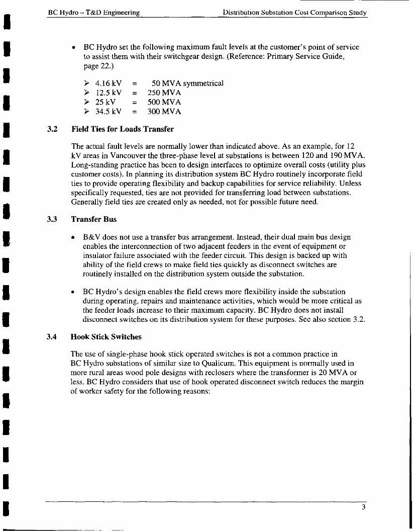
0 BC Hydro set the following maximum fault levels at the customer’s point of service to assist them with their switchgear design. (Reference: Primary Service Guide, page 22.)
> 4.16 kV = 50MVAsymmetrical > 12.5kV = 250MVA > 25 kV = 500MVA > 34.5 kV = 300MVA
3.2 Field Ties for Loads Transfer
The actual fault levels are normally lower than indicated above. As an example, for 12 kV areas in Vancouver the three-phase level at substations is between 120 and 190 MVA. Long-standing practice has been to design interfaces to optimize overall costs (utility plus customer costs). In planning its distribution system BC Hydro routinely incorporate field ties to provide operating flexibility and backup capabilities for service reliability. Unless specifically requested, ties are not provided for transferring load between substations. Generally field ties are created only as needed, not for possible future need.
3.3 Transfer Bus
0 B&V does not use a transfer bus arrangement. Instead, their dual main bus design enables the interconnection of two adjacent feeders in the event of equipment or insulator failure associated with the feeder circuit. This design is backed up with ability of the field crews to make field ties quickly as disconnect switches are routinely installed on the distribution system outside the substation.
0 BC Hydro’s design enables the field crews more flexibility inside the substation during operating, repairs and maintenance activities, which would be more critical as the feeder loads increase to their maximum capacity. BC Hydro does not install disconnect switches on its distribution system for these purposes. See also section 3.2.
3.4 Hook Stick Switches
The use of single-phase hook stick operated switches is not a common practice in BC Hydro substations of similar size to Qualicum. This equipment is normally used in more rural areas wood pole designs with reclosers where the transformer is 20 MVA or less. BC Hydro considers that use of hook operated disconnect switch reduces the margin of worker safety for the following reasons:
3

BC Hydro - T&D Engineering Distribution Substation Cost Comparison Study
0 Increases the risk of inappropriate contact with energized bus.
Greater reliance on tools that must be maintained.
Workers would not be as protected from step and touch potentials because they would not be standing on a designated ground mat while operating the device.
0 Use of “hot sticks” is also weather dependent and could limit the operating and maintenance flexibility as compared to the ganged operated disconnect switches for there would be an increase in set-up time required associated with these activities.
0 Would be an increase in space requirements of the substations to insure sufficient room to use the “hot sticks” which would mean losing some of the substations’ compactness.
3.5 Application of Series Reactors
Perhaps the most notable difference in the design approach is the application of series reactors by BC Hydro to limit the magnitude of the fault current in our large capacity substations that supply distribution systems. It is BC Hydro’s view that, if not controlled, these high fault levels will be imposed on all distribution feeders resulting in:
Increased costs of feeder breakers, bus work and disconnect switches. Limitations in the application of downstream devices such as reclosers and fuses. Exposure of equipment (e.g. transformers) to higher fault levels. Joint use of pole for power distribution and communications may be precluded. Step-down transformers, having common impedance, can be relocated more readily in the system.
Arguments against the use of series reactors include:
Additional cost. Additional space requirements. Regulation through the reactor.
It appears prudent for BC Hydro to undertake a review of the application of feeder reactors in its substations. This review should consider issues beyond the substation fence.
3.6 Equipment Foundations
When visiting one of the PG&E substations B&V had designed, the extensive use of independent footings in the design of their compact arrangement was observed. In similar circumstances BC Hydro would install a common slab for stations due to cost savings and seismic considerations.
4

BC Hvdro - T&D Engineering Distribution Substation Cost Comparison Study
3.7 Reduction in Main Bus Current Carrying Capacity
Reduction of Main Bus Current Carrying Capacity - B&V rightly points out that for the transformers indicated a rating of 2500 amperes for the main 25 kV is not required.
0 However, since BC Hydro’s bus work design also covers 12 kV substations, which B&V’s proposed design does not, there is trade-off between maximizing the bus work design and minimizing material handing and storage costs.
Nonetheless, B&V’s idea of using aluminium angle is an interesting one, which BC Hydro will explore.
3.8 138 kV Portion of the Substation
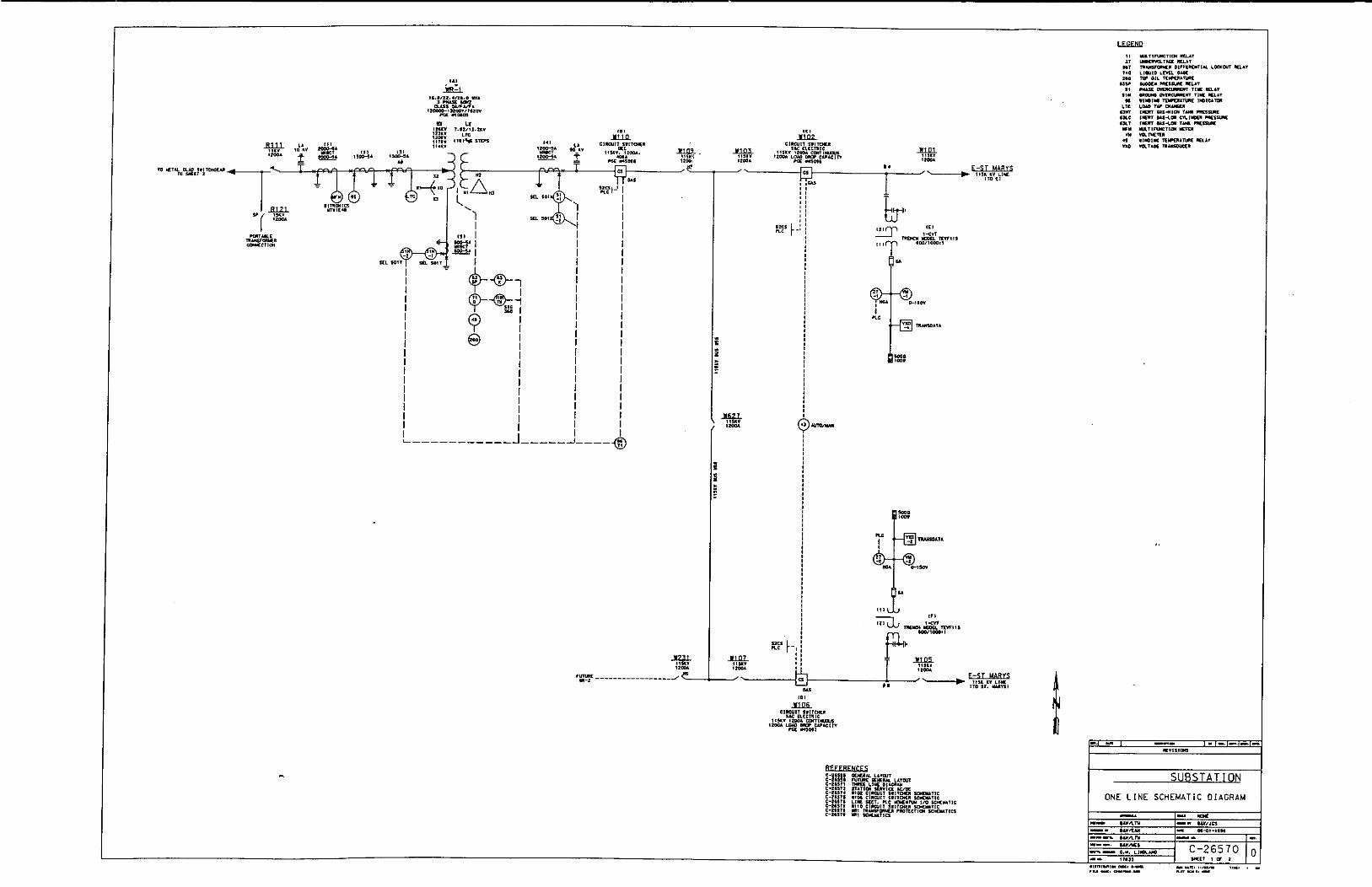
The proposed two 138 kV line circuit switchers are not required for this application. For the initial one transformer arrangement, the station is supplied via a transmission line tap and 1D21 from one line and 1D22 is Normal Open. In case of a transmission line outage 1D1 opens and 1D2 closes automatically and the substation is re-energized via the tap from the second line. BC Hydro accepts the risk of a fault on the 138 kV interconnecting bus until the second transformer is added.
3.9 Other Design Matters
Measures to protect the substation from lightning and seismic activity were not evident in the B&V design. There were no indications given on the drawings provided nor was there any evidence seen during the site visits. When questioned about these areas B&V indicated it had not been a problem to date or that it could be added to the design with minimum cost.
0 The question of equipment accessibility for certain equipment mounted over the main bus is also an issue for the owner of the substation indicated the main bus was to be taken out of service to gain access to this equipment.
The use of standard 19-inch P&C rack, without steel sides, as proposed by B&V would be a problem for BC Hydro’s field staff. They already have miss-operation issue of P&C equipment due to maintenance activities and the use of the proposed racks in the BC Hydro system would increase the risk of operation-operation occurring.
5

BC Hydro - T&D Engineering Distribution Substation Cost Comparison Study
4. DIFFERENCES I N APPROACH TO THE DESIGN - MANITOBA HYDRO
4.1
4.2
4.3
4.4
Application of Series Reactors
In most instances, Manitoba Hydro does not use feeder reactors to limit fault currents outside the substation but instead increase the impedance of the step-down transformer.
Use of Transfer Bus
Replace the transfer bus design with a dual main bus arrangement and have the loads fed from separate sources, i.e. two substations.
Equipment Operating Temperatures
Equipment cost would be higher due to the increasing the lower limit of the temperature range required for the equipment, -50°C from -40°C.
Equipment Arrangement and Control Building Design
Manitoba Hydro’s cost estimate would include more land for their equipment arrangements due to access requirement for line trucks during maintenance activities.
Manitoba Hydro normally includes a washroom and a workshop in their control building design resulting in a larger size at higher cost.
5. COMPARISON O F COSTS - BLACK & VEATCH
To provide for an “apples to apples” comparison of the cost of providing similar facilities by the three parties a detailed analysis of the constituent cost components was necessary. Actual BC Hydro costs were compared to B&V and Manitoba Hydro cost estimates. This comparison is shown on Table 1 (Appendix 5) . Although the intention was to provide as detailed a comparison as practical, it was not possible in most instances to compare direct component costs due to different designs, terminology and level of detail. In most cases, it was considered sufficient to compare costs at the general classification level, i.e. design, equipment installation, etc. In addition, to make the comparison and to ensure uniformity of scope, certain actual construction costs for the BC Hydro Qualicum substation were removed from the cost breakdown. These are shown at the bottom of Table 1 (Appendix 5).
The actual costs of the design and installation of the Qualicum Substation were reported in 1998 Canadian dollars. For comparison purposes, B&V (in year 2000 US dollars) and Manitoba Hydro estimate costs (in year 2000 Cdn. dollars) were converted to 1998 Canadian dollars using the conversion factors shown on Table 1 (Appendix 5).

BC Hydro - T&D Engineering Distribution Substation Cost Comparison Study
5.1 Substation
0 Details of B&V estimate and assumptions are contained in their report contained in Appendix 6. For their estimates, B&V assumed they would be the prime contractors for the project responsible for the engineering, procurement and construction phases of the work (EPC contractor).
0 Overall BC Hydro’s actual direct costs compared favourably with B&V’s estimated direct cost with Hydro’s being approximately 12%.
5.2 Engineering
The engineering costs were broken down into the following by tasks: Project Management, Contracts, Civil, Station Design, Protection, Control, Communication and Environment. B&V had the lowest cost for these tasks, totalling about $203,000. BC Hydro actual costs were $469,000. BC Hydro costs include the cost of interfacing with other external agencies, manufacturers and consultants. All of such costs were not included in B&V’s estimate. In addition, the Qualicum Substation was the first of this type of substation design for BC Hydro and hence included developmental engineering costs, which would not be required for future similar stations. Table 1 (Appendix 5 ) shows a breakdown of forecast costs for a similar substation under the column “BC Hydro costs estimated for additional.. .”. B&V’s estimate assumed that they would use a standard design already accepted by BC Hydro such that an extensive review, debate and design modification would not be required.
5.3 Equipment and Materials
0 Costs in this category include Major Equipment, Electrical, Mechanical, P&C and Communication Material and Quality Assurance.
B&V’s estimate is based on their conducting the project on an Engineer, Procure and Construction (EPC) basis. In their report they included a 12% mark up on the equipment cost to cover contingency, profit and risk. In the comparison table this has been separated to more readily compare equipment costs. The estimated cost for the major piece of equipment, the transformer, is very close to the actual cost paid by BC Hydro. B&V achieve some cost reduction by the use of hook stick disconnects, but the use of four CS results in higher costs. On balance, B&V estimated cost for equipment is approximately 13% higher than BC Hydro’s actual costs.
In contracting the supply of equipment, B&V appeared to place greater emphasis than BC Hydro on the equipment manufacturer bring responsible for the design and supply of the associated control and protection systems, i.e., a more modular approach to equipments supply. This approach probably contributed to their lower in-house design costs.

BC Hydro - T&D Engineering Distribution Substation Cost Comuarison Studv
5.4 Construction
Construction costs include Construction Contract Management, Civil Work, Electrical Installation and Testing and Commissioning. The actual BC Hydro costs for this phase of the work was $8 18,860 compared to the B&V estimated cost of $1,045,730. It appeared to be B&V’s practice to employ a Professional Engineer in the role of the “On Site Construction Manager”, who in addition to managing subcontractors and B&V craftsmen, is responsible for making minor design changes. It was noted that it is common practice for small installations and equipment change-outs to be done with little or no pre-design. The Construction Manager makes engineering decisions and any “as- built” drawing submitted to the design office. The additional field cost in the use of a Professional Engineer in the role of Construction Manager are seen to have three distinct advantages:
Reduced the reliance on “head-office” design support (Engineering cost saving).
Provides developmental and training experiences
Enhanced customer relations/satisfaction at the “field level”
On-site construction of the project was assumed to take 5 months. This is similar to the process used by BC Hydro for the construction of the Qualicum Substation. Two main contracts were let: Civil Work - 1998 Stage (Q8-2000) and Electrical Work - 1998 Stage (Q8-2026). An on-site Construction Officer managed each contract. The total duration of the project extended from 15 April 1998 to 1 October 1998, a 6-month time period. The actual in-service date was delayed to 27 November 1998 by late delivery of the transformer.
6. COMPARISON OF COSTS - MANITOBA HYDRO
6.1 Substation
Manitoba Hydro make extensive use of internal forces in the design and construction of their substation. Their substation was the largest of those proposed by the participants, measuring 100m x 60 m, compared with BC Hydro’s 46m x 61m, and B&V’s 65m x 65m. All three participants included a control building in the facility. Manitoba Hydro’s was the largest measuring 13m x 13m, compared with BC Hydro’s at 8m x 6m and B&V’s at 7m x 4m.
8 I
BC Hydro - T&D Engineering Distribution Substation Cost Comparison Study
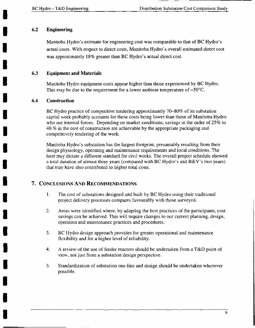
6.2
6.3
6.4
7.
Engineering
Manitoba Hydro’s estimate for engineering cost was comparable to that of BC Hydro’s actual costs. With respect to direct costs, Manitoba Hydro’s overall estimated direct cost was approximately 18% greater than BC Hydro’s actual direct cost.
Equipment and Materials
Manitoba Hydro equipment costs appear higher than those experienced by BC Hydro. This may be due to the requirement for a lower ambient temperature of -50°C.
Construction
BC Hydro practice of competitive tendering approximately 7040% of its substation capital work probably accounts for these costs being lower than those of Manitoba Hydro who use internal forces. Depending on market conditions, savings in the order of 25% to 40 % in the cost of construction are achievable by the appropriate packaging and competitively tendering of the work.
Manitoba Hydro’s substation has the largest footprint, presumably resulting from their design physiology, operating and maintenance requirements and local conditions. The later may dictate a different standard for civil works. The overall project schedule showed a total duration of almost three years (compared with BC Hydro’s and B&V’s two years) that may have also contributed to higher total costs.
CONCLUSIONS AND RECOMMENDATIONS
1. The cost of substations designed and built by BC Hydro using their traditional project delivery processes compares favourably with those surveyed.
Areas were identified where, by adapting the best practices of the participants, cost savings can be achieved. This will require changes to our current planning, design, operation and maintenance practices and procedures.
BC Hydro design approach provides for greater operational and maintenance flexibility and for a higher level of reliability.
A review of the use of feeder reactors should be undertaken from a T&D point of view, not just from a substation design perspective.
Standardization of substation one-line and design should be undertaken whenever possible.
2 .
3.
4.
5.
BC Hydro - T&D Engineering Distribution Substation Cost Comparison Study
6. The possible use of different design concepts and ideas such as using aluminium angles for bus work and using standard side less P&C racks should be explored more fully.
7. Continue to drive down total project costs, increase efficiency and productivity.
8. Continue to contact others in the industry on a regular basis to keep abreast of new ideas, concepts and different ways of doing business.
10


Appendix 1 Work Scope and Assumptions
Appendix 1 Work Scope and Assumptions
1. Introduction
Develop a project cost estimate and schedule to engineer and construct the Initial Phase - 50 MVA of a 138 kV/25 kV, 100 MVA substation based on the following criteria and equipment arrangement (the “Work”) shown on the two attached Single Line Diagrams:
Initial Stage - 50MVA Ultimate Phase - 100MVA
2. General Assumptions
The contractor is permitted the freedom to introduce innovative, cost saving initiatives in equipment selection and design and construction methodology. Equipment specifications and engineering practices must comply with accepted national and international standards. Safety practices, as they relate to personnel safety and operating practices, shall not to be compromised.
Use of good engineering practices in the design, equipment specification and procurement, construction, commissioning, construction management and project management of the substation.
Level site, no special soil conditions and no requirement for piles.
Facility must be capable of operation between -30°C to 40°C.
For the purposes of this exercise “the substation” is defined as those facilities contained within the surrounding fence line plus 10 feet.
The Owner does not unduly delay the contractor.
Facility shall be capable of remote control and operation, i.e. no permanent on site staff.
Design of the facilities must consider the long term operational and maintenance costs, i.e. a low initial capital, high operating cost, and design would not be acceptable.
Progress payments will be made to the contractor, i.e. contractor will not be required to finance the project.

Appendix 1 Work Scope and Assumptions
I 1 I I I 1 I 1 I I I 1 I I I I I I A1 - 2
3. Other Assumptions
Assume no washrooms or potable water required in the station.
Assume a minimum soil bearing capacity of 250 kPa and a ground resistively of 475 ohmdmetre.
Assume three phase MVNSLG kA fault levels of:
> 138 kV 5000/20 (Initial Phase) 2150/5.9 (Final Phase) > 25kV 960/20 (Initial Phase) 32W7.6 (Final Phase)
Shield wires on 138 kV lines extending 1 km out from station.
4. Project Direct Cost Estimate
The direct cost estimate shall be broken down in accordance with the attached Work Breakdown Structure (WBS). Direct cost is defined as those costs directly related to the Work excluding mark-ups on subcontracted services, material and equipment also interest charges, corporate overheads and profit margin.
Work to be included in the project estimate and schedule.
Clearing and preparation of the site, including drainage.
Provision, as may be required, of all required foundations, buildings and structures.
Provision, as may be required, of the on-site portions of any required services such as water and sewer systems, etc. to the fence line, including the connection at the fence line.
Procurement of all equipment necessary to complete the Work to accepted national or international codes and standards.
Provision of all engineering services and site labour to complete the Work.
On-site handing and storage of all materials and equipment.
Seismic requirements for foundations, buildings, structures and equipment shall conform to IEEE Standard 693 (assume Seismic Zone 3).
Assembly, finishing, installation and testing of all systems and equipment.
Temporary on-site facilities used by the contractor and subcontractors.
As-built drawings, instruction manuals, installation and commissioning documentation.
I I I 1 I I I I I I I I 1 I I I I I I A 1 - 3
Appendix 1 Work Scope and Assumptions
Two-year warranty on constructed facility.
Training of the Owner’s staff in the operation and maintenance of the facilities (at the site).
Compliance with applicable Federal, Provincial, Municipal laws and/or regulations, including environmental regulations, as they may relate to the work.
5. Work Not Included in the Project Estimate and Schedule
Soil investigations.
Public consultation.
Licenses and permits.
Witnessing of the contractor’s functional testing by the Owner of the completed installation.
Remote end testing by the Owner necessary to integrate the completed facility into the main electrical system.
Construction of access road to fence line.
Provision of the external portion of required services such as water, sewer and telephone services, as may be required, to the fence line.
Construction power to the fence line.
Remote control facilities except that necessary to remotely control and operate the facility.
Land purchase.
HV transmission and distribution facilities to the fence line.


Appendix 2 Work Breakdown Structure (Substation Infrastructure)
I
Engineering Management Services
Civil Design 8 3 2 0 0 Management
Station Design P 8 C Design 8 3 5 0 0 8 3 6 0 0
Communication Environmental Design Services 83800 8 3 9 0 0
Construction Services HOOOO
Construction Testing 8 Management Commissioning
H3100 H3650
Civil Works Installation Work H3200 H3500
Materials M 3 5 1 0 M 3 5 9 0


~~
Appendix 3 Task Description
Appendix 3 Task Description
A100 - Project Management
Provide project management services to engineer, procure and construct Stage 1 of the 138/25 kV substation (salary and expenses only).
B3100 - Equipment Contract Management
Provide services to procure major electrical, mechanical and communication equipment, (salaries and expenses only). Deliverables include:
0
0
0
Technical requirements of major equipment contracts. Commercial portion of all equipment tender documents. Administration of the public tendering process. Administration of all awarded contracts.
B3200 - Civil Design
Provide civil design services for site preparation and construction of required footings, structures, etc. (salaries and expenses only). Deliverables include:
0
0
0 As-built drawings.
Text and drawings for the construction contracts. Preparation of construction drawings on schedule.
B3500 - Station Design
Provide electrical and mechanical design services (salaries and expenses only). Deliverables include:
0
0 As-built drawings.
Text and drawings for the construction contract. Preparation of construction drawings on schedule.
B3600 - P&C Design
Provide protection and control design services (salaries and expenses only). Deliverables include:
0
0 As-built drawings.
Text and drawings for the construction contract. Preparation of construction drawings on schedule.
A3 - 1
Appendix 3 Task Description
B3800 - Telecommunication Design
Provide telecommunication design services (salaries and expenses only). Deliverables include:
As-built drawings.
Text and drawings for the equipment procurement contract. Text and drawings for the construction contract. Preparation of construction drawings on schedule.
B3900 - Environmental Services
Provide site environment advice throughout the project and a management plan for the construction phase of the work (salaries and expenses only).
H3100 - Construction Contract Management
Cost of construction contract management services associated with the construction of the substation (salaries and expenses only). Includes preparation of construction contracts (site preparation and electrical installation), contract award and management of site work. Site safety co-ordination.
H3200 - Civil Work
Cost of site labour, materials and miscellaneous equipment, supplied by the Owner and/or a contractor related to site preparation, installation of footings, civil structures, etc.
H3500 - Installation Work
Cost of site labour, materials and equipment, supplied by the Owner and/or a contractor to install the electrical, mechanical, P&C and communications equipment and systems.
H3650 - Testing and Commissioning
Salaries and expenses related to the testing of electrical, mechanical, P&C and communication systems, this includes:
0 Testing and commissioning documentation. 0
0 Co-ordination of site testing. 0
Performance of equipment and system acceptance tests.
Provision of erectiodinstallation supervision for major items of equipment.
M3510 - Major Equipment
Includes the actual cost of major equipment including power transformers, potentialkurrent transformers, circuit breakers, disconnects, station battery systems, protection and control equipment, communication equipment.
A3 - 2

Appendix 3 Task Description
M3591- Electrical, Mechanical, P&C and Communication Material
Includes the actual cost of electrical material (other than that in M35 lo), including bus work and associated insulator and fittings, control and communication cables, conduit, fittings, grounding materials, etc.
QOOO - Quality Assurance
Salaries and expenses related the provision of Quality Assurance services (factory inspection and expediting) on major equipment.
A 3 - 3

l L 1 1 6
t 1,102 I 101C83 102CB3
0 1 CB3
1L115
t /
'92 lCVT2
102 - 101
25CB2
C83 2502C82 25
CB3
25VT22 I
2501 25VT2 1
25RX22 25012; 25032 1 250322 ( 1200 A)
I k A 12.5%
( l 2 O 0 A) 250221 25CB2 1 250121 25RX21
1kA 12.5%
;I I
b-t 25F53
TYPICAL FEEDER DESIGNATIONS
Q P 250cxL
e $ 25cx1 3 2SNVTCX1
I e 250CX2
25CX2 e 25NVTCX2
Lf).-- 25F55 25F65 +--<t'
138 kV - 25 kV Substation
Ultimate Phase - 100 MVA

1L116 1L115
1DlCBl 6 lC8l
250 1 2502 C83
(1200 A)
J 1 2584 2502CB 1
2501 1
25D2CE 1 J 250 1 CB3
2502 C83 1 2502C82
I 2501 1
6 0 0 In CJ v
c
m In ri
25VT 1
250151 25C85 1 250251 250351 250361 2501 61
25F52 U -c
A
6 0 0 In r4 v
r4 (D ln ri
RATINGS OF EQUIPMENT
lRANSFORMERS
T1 - PAUWELS 130 kV DELTA/ 25.2 kV CRO. Y. 30-60 nZ - 25/33.3/41.7 MVA; 0 W . O W . O N A F ; 65' C nv LGQ TAPS t 12.52 IN 5 10 STEPS
- CENTRAL 10-60 HZ MAiONEV 50 kVA: 24.94 ONAN. kV 65'C GRO. Y/ 14.4 kV, 120 v
VOL TAG€ TRANSFORMER
E - WOTEM. MPE -7. 120/200/1. 14.4 kV/ l20V/72V
CIRCUIT ERE4KERS
- SIEMENS. TYPE CPV CIRCUIT SWITCHER 145 kV. 1200 A. 20 Id (SF6)
25c852 } MERUN GERIN. M P E SFI-OUTDOOR. 25 kV. 1200 4 12.5 kA 2x.RW
DISCONNECTS
] PASCOR. 145 kV. 1200 A. TYPE VBPA !01c85 101C91 - SOUTHERN STATES. 145 kV. 1200 A. TYPE EC-IV a - S & C. 2 7 kV. 100 A. TYPE XS. ;USE LINK 4 a
-1 "" } TRAVIS. 25 kV. 2000 A. N P E UL rn
7
E5xil. 250552.250561, i3D.Xz )
SURGE ARRESTORS
- JOSLYN. TYPE ZS. LINE CLASS 3. UCOV - i ; 5 N - ABB. TYPE EXLIM 2. C U S S - ~ N T E R M E ~ . . uccv - 17 N
FEEDES CABLES
LOCATlON:
138 kV - 25 kV Substation
Initial Phase - 50 MVA


063


Distribution Substation Cost Comparison Study
Prepared for:
BC HYDRO
By:
Black & Veatch Corporation B&V Project 99931
December 14,2000
la. BLACK & VEATCH

Distribution Substation Cost Corn par is on Study
1 .O Introduction
The purpose of this study is to provide BC Hydro with cost estimates for engineering, procuring and constructing a distribution substation to be compared with their internal costs for actual substation projects and with similar typical costs being prepared by other independent parties. This study is based on One-Line diagrams provided by BC Hydro. A number of changes to the One-Line diagrams are proposed and are included in the estimated pricing. The cost estimate is based on substations designed and built by Black & Veatch and reflect accepted construction and operations practices common in the U.S. electric utility industry.
This report consists of: A narrative describing the station configurations that are priced and an explanation of the changes we propose. A narrative summarizing our cost estimate and briefly discussing the project schedule. One-line diagrams of the initial and ultimate station configurations upon which our cost estimates are based. Example drawings used to illustrate our proposed design and to help with the price estimates.
Tables summarizing our pricing estimates,
2.0 Substation Configuration Changes
Attachment A includes One-Line Diagrams of the initial and ultimate configurations that we would propose for this station. In general, this is a distribution station with an “In and Out” high side in which a 138 kV transmission line is brought into the station, through switching devices and back out without a line termination. In the event of a line fault, the terminals at each end would detect the fault and open, de-energizing the line. The line switching devices in this station (138 kV circuit switchers in our proposed configuration) would open. Then the two ends of the line would reclose, with at least one of them doing so successfully. The circuit switcher on the successful side would close, and the station
L:\WP233\9993 l\BCHydro 1 1 21 I3IOO
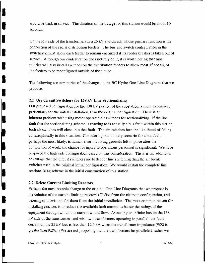
would be back in service. The duration of the outage for this station would be about 10 seconds.
On the low side of the transformers is a 25 kV switchrack whose primary function is the connection of the radial distribution feeders. The bus and switch configuration in the switchrack must allow each feeder to remain energized if its feeder breaker is taken out of service. Although our configuration does not rely on it, it is worth noting that most utilities will also install switches on the distribution feeders to allow most, if not all, of the feeders to be reconfigured outside of the station.
The following are summaries of the changes to the BC Hydro One-Line Diagrams that we propose.
2.1 Use Circuit Switchers for 138 kV Line Sectionalizing Our proposed configuration for the 138 kV portion of the substation is more expensive, particularly for the initial installation, than the original configuration. There is an inherent problem with using motor operated air switches for sectionalizing. If the line fault that the sectionalizing scheme is reacting to is actually a bus fault within this station, both air switches will close into that fault. The air switches face the likelihood of failing catastrophically in this situation. Considering that a likely scenario for a bus fault, perhaps the most likely, is human error involving grounds left in place after the completion of work, the chance for injury to operations personnel is significant. We have proposed the high side configuration based on this consideration. There is the additional advantage that the circuit switchers are better for line switching than.the air break switches used in the original initial configuration. We would install the complete line sectionalizing scheme in the initial construction of this station.
2.2 Delete Current Limiting Reactors Perhaps the most notable change to the original One-Line Diagrams that we propose is the deletion of the current limiting reactors (CLRs) from the ultimate configuration, and deleting of provisions for them from the initial installation. The most common reason for installing reactors is to reduce the available fault current to below the ratings of the equipment through which this current would flow. Assuming an infinite bus on the 138 kV side of the transformer, and with two transformers operating in parallel, the fault current on the 25 kV bus is less than 12.5 kA when the transformer impedance (%Z) is greater than 9.2%. (We are not proposing that the transformers be paralleled, rather we
L:\WP233\9993 1BCHydro 2 1 21 14/00

view this as the worst case design consideration.) Specifying the transformers with this impedance would add little or nothing to the price of these units. There are a number of advantages to this approach.
Having the impedance inside the transformer will improve the voltage regulation on the 25 kV feeders. The load tap changers (LTC) on the transformers have no way to compensate for the voltage drop across the CLRs. The cost of the CLRs, along with related supports and foundations, is saved. The space required for the CLRs is saved which will reduce the footprint of the station, and will simplify the design of the distribution switchrack such that a relatively compact box structure can be used. It simplifies the layout such that metal-clad switchgear could be used, provided a main and transfer configuration was operationally acceptable. The bus configuration in the BC Hydro One-Line is difficult to accomplish in metal-clad switchgear.
2.3 Delete Transfer Bus Of our proposed changes, the one that will have the greatest effect on the operation of the 25 kV switchrack is the deletion of the transfer bus. Besides saving the cost of the bus, it also saves one gang-operated switch per feeder bay. The purpose of the transfer bus is to allow any feeder breaker to be taken out of service and to have the feeder load transferred to any other feeder breaker. However, there is a subtle limitation to the original configuration. If a second feeder breaker must be taken out of service, the load on its feeder must be transferred to the same breaker that the first out-of-service breaker’s load was transferred to. In our proposed configuration, often referred to as the tandem bus Configuration, if a feeder breaker is taken out of service, its load is transferred to the other breaker in its bay. More than one feeder breaker can be taken out of service without the entire load ending up on the same breaker. The only limitation is that if both feeder breakers in a bay need to be taken out of service, feeder switching outside of the station will be required to continue to serve the load.
Y 2f Use Hook-Stick Switches We propose to use single pole, single throw hook-stick switches in place of the gang- operated switches for isolating the 25 kV breakers. This will reduce the cost of the switches, and reduce the installation cost. It will also reduce the maintenance cost through the life of the station. Aside from these reasons, it is our experience that at
L:\WP233\9993 1 BCH ydro 3 1 21 14/00

distribution voltages many of our clients prefer hook stick switches because of their simplicity and higher reliability.
2.5 Relocate Station Service Transformers The station service transformers are connected to the 25 kV main buses, rather than to the transformer secondaries. Electrically, this makes little difference. In our design, it allows them to be mounted inside of the box structure, rather than on an additional structure that would not otherwise be required. The voltage transformers will also be mounted inside the box structure and fused to the main buses. In the initial configuration, one station service source would be the main distribution bus, as shown on the Initial One-Line Diagram. A second source would be brought into the station from local distribution to a pad mount transformer located near the control enclosure. In the ultimate configuration, this pad mount transformer and its feeder are removed, and a second transformer would be mounted in the box structure.
2.6 Change Capacitor Bank Feed We recommend feeding the 25 kV capacitor banks from fuses connected to the main buses. Switching of the banks would be done by vacuum switches mounted at the banks, rather than with breakers in the switchrack. At least one of the capacitor banks would be fitted with reactors to limit the back-to-back switching transient to acceptable levels. The banks would be internally fused with neutral voltage unbalance relay protection that would trip within approximately one second for an unbalance characteristic of a developing can failure. The fuses would clear any high current (presumably phase-to- phase or phase-to-ground) faults. The equipment costs for this configuration are less than would be required on the original configuration, as an entire feeder bay (including breakers) is no longer needed.
2.7 Reduce the Ampacity of the Main Bus Many aspects of our proposed configuration are based on the operational requirement that the two transformers are never operated in parallel. Allowing for an overload of 20 percent above the top rating of one of these transformers (50 MVA) requires less than 1,200 amperes. We have selected a 1,500 ampere rating for the main bus. This allows us to use a single aluminum angle for the bus conductor, and the other buses in the 25 kV switchrack. Aluminum angle is inexpensive and very easy to install. Fittings are not required to mount it on insulators or to land a four-hole pad from a jumper on it.
L:\WP?33\9993 I\BCHydro 4 1 u 14/00

2.8 Use a Single CVT for 138 kV Hot Line Sensing It is our understanding that the original BC Hydro One-Line diagram calls for three phase potential devices on the 138 kV for input into the line sectionalizing scheme. In our scheme, a single CVT is used to provide input to the 27/59 relay that is central to the sectionalizing scheme.
2.9 MetaI-CIad Switchgear We have not based our proposed configuration on metal-clad switchgear. However, use of switchgear is an idea that is worth considering. It is our experience that an open air box structure is somewhat less expensive than metal-clad for distribution. However, the following features of metal-clad installations often outweigh the additional expense for many utilities:
Metal-clad is more compact which can be important for sites with limited space. Many consider metal-clad to be a better design aesthetically, which is important in urbadsuburban settings. Metal-clad provides a protected work space which may be quite popular with your operations, maintenance and test personnel. There is much less design work for your staff in a metal-clad installation as most of the design is done by the switchgear manufacturer. This can be an advantage if your design staff is resource limited.
3.0 Substation Design Features
Our proposed design uses a low profile arrangement for the 138 kV equipment and buswork. Attachment B has drawings from a 115 kV station with this bus and equipment arrangement. We use a box structure for the low side. Attachment C has drawings from a stations with a similar style structure done at 15 kV. Although the examples are from 115 kV and 15 kV, they would only need to be marginally larger to accommodate your voltages.
For our cost estimates, we have assumed that the size of the yard would about 65 meters square. This would allow room for mobile transformers and easy access to all equipment. It is often the case that a square site with plenty of space is not available. By using some creative bus design for the 138 kV layout, and perhaps metal-clad switchgear for the distribution, our basic design could be made to fit on a much smaller, or oddly shaped, piece of land.
L:\WP233\9993 I WCHydro 5 1 21 14100

For the purposes of this report and the associated cost estimates, the 138 kV switchyard will be installed in its final configuration during the initial build out of the station. This will include a disconnect switch for the connection of the second transformer.
The following summarize the control and relaying features of our proposed design. The only relaying for the 138 kV portion of the station is a programmable logic controller (PLC) based sectionalizing scheme. The PLC, as well as all control switches for the 138 kV equipment, will be on a single 19 inch rack (or metric equivalent) in the control house. The transformers will be protected by a differential relay that includes overcurrent elements. The zone of protection of the differential scheme is established by the bushing current transformers (BCTs) in the high and low side transformer bushings. In case of a differential trip, in the initial configuration the high side circuit switcher is tripped. In the ultimate configuration, the high side circuit switcher and the low side main breaker are tripped. Tie breaker 25CB3 can be closed remotely to re-energize the outaged main bus. Each transformer will have a 19 inch relay rack in the control house for its relaying and associated control switches. The 25 kV main buses are protected by overcurrent relays that get their current inputs from BCTs on the low side of the transformer. This scheme will trip the high side circuit switcher. The overcurrent relays are located on 19 inch relay racks with the transformer protection. These relays will be set to coordinate with the settings of the feeder overcurrent relays and the damage curve of the transformer. The feeder relaying will be installed by the breaker manufacturer in the control cabinets of the feeder breakers. There will be control switches in the control cabinets and on a 19 inch rack in the control house. Reclose cutout switches will be in the breaker control cabinets.
The feeder breakers will have SCADA control, status, alarm and metering functions. These would be accomplished through a PLC connected to a local area network. This network would integrate all other SCADA/RTU functions, and would communicate to BC Hydro’s existing SCADA master through a protocol converter. This system would be housed in a single 19 inch relay rack.
L:\WP233\9993 1 \BCHydro 6 1 21 1 4/00
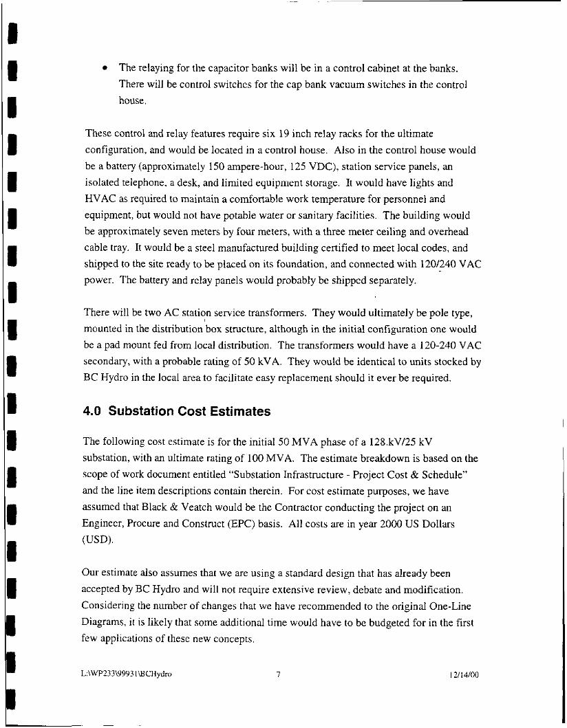
The relaying for the capacitor banks will be in a control cabinet at the banks. There will be control switches for the cap bank vacuum switches in the control house.
These control and relay features require six 19 inch relay racks for the ultimate configuration, and would be located in a control house. Also in the control house would be a battery (approximately 150 ampere-hour, 125 VDC), station service panels, an isolated telephone, a desk, and limited equipment storage. It would have lights and HVAC as required to maintain a comfortable work temperature for personnel and equipment, but would not have potable water or sanitary facilities. The building would be approximately seven meters by four meters, with a three meter ceiling and overhead cable tray. It would be a steel manufactured building certified to meet local codes, and shipped to the site ready to be placed on its foundation, and connected with 1201240 VAC power. The battery and relay panels would probably be shipped separately.
There will be two AC station service transformers. They would ultimately be pole type, mounted in the distribution ‘box structure, although in the initial configuration one would be a pad mount fed from local distribution. The transformers would have a 120-240 VAC secondary, with a probable rating of 50 kVA. They would be identical to units stocked by BC Hydro in the local area to facilitate easy replacement should it ever be required.
4.0 Substation Cost Estimates
The following cost estimate is for the initial 50 MVA phase of a 128.kV/25 kV substation, with an ultimate rating of 100 MVA. The estimate breakdown is based on the scope of work document entitled “Substation Infrastructure - Project Cost & Schedule” and the line item descriptions contain therein. For cost estimate purposes, we have assumed that Black & Veatch would be the Contractor conducting the project on an Engineer, Procure and Construct (EPC) basis. All costs are in year 2000 US Dollars (USD).
Our estimate also assumes that we are using a standard design that has already been accepted by BC Hydro and will not require extensive review, debate and modification. Considering the number of changes that we have recommended to the original One-Line Diagrams, it is likely that some additional time would have to be budgeted for in the first few applications of these new concepts.
L:\WP233\9993 1WCHydro 7 1 21 14/00

No attempt is made to budget resources for BC Hydro’s internal efforts.
4.1 Design Costs The following cost information is presented in the format required by the scoping document. Approximate overall hours are provided for each line item. A cost of approximately USD 180,000 is the total cost of the Engineering functions for this project (line items A100, B3100 through B3900). We anticipate that this price would drop with each additional project of this type that we do as our staff becomes familiar with your standards and practices, and discovers efficiencies that are not apparent at this time and could be implemented through collaborative efforts between the B&V and BC Hydro project teams.
A100 - Project Management. We would anticipate the B&V Project Manager, Clerical Staff and other support personnel would spend approximately 400 hours on this project.
B3 100 - Equipment Contract Management. These costs include specifying and procuring all equipment and material used to build the substation. It is assumed that B&V
. . . procurement procedures will be followed. Our procedures do .nu requ- U
process. The B&V Project Engineer, Staff Engineers and Procurement Specialists will do this work. We anticipate 800 hours will be spent in these activities.
B3200 - Civil Design. These costs include all aspects of a site grading design, designing all required foundations, the oil spill containment system for the transformers, and all required steel structures. Hours for the procurement of the steel structures and other materials are included in line item B3 100. We anticipate 400 hours will be spent on these activities.
B3500 - Station Design. This includes all aspects of the outdoor physical/electrical design (grounding, buswork, layout, lighting, raceway, etc.). We anticipate spending 400 hours on these activities.
B3600 - P&C Design. This includes preparation of the One-Line Diagram, AC and DC Schematics, SCADA and wiring diagrams. We anticipate spending 400 hours on this aspect of the project.
L:\WP233\9993 1 \BCHydro 8 I 21 I 4/00

B I I I I I 1 1 1 I I i I I I 1 1 1 II
B3800 - Telecommunication Design. The only communications design is the installation of a four-wire telephone service. This is a relatively simple part of the project. The hours for this design are distributed in the other line items, conduit for the phone line is in B3500, the telephone isolation system will be purchased as part of the control enclosure, and the cabling will be shown in the wiring.
B3900 - Environmental Services. To the extent that environmental services are required, they will be conducted as part of other line items. Based on the assumptions listed in the scoping document, no significant environmental services should be required. Many of the functions that BC Hydro might historically include in this part of the work are included in other line items. One example is the erosion and stormwater runoff plan that would be a part of the civil design and construction management.
4.2 Construction Costs We estimate the total cost of construction (sum of items H3 100, H3200, H3500 and H3650) to be USD 715,400, broken down as follows:
H3 100 - Construction Contract Management. This will largely be conducted by a B&V Construction Manager (CM) that will be supported by the home office design staff. The CM will be on site throughout all construction, will administer all subcontracts and will supervise B&V craftsmen. We anticipate that the construction of this project would take approximately five months. We would budget approximately USD 125,000 for this function. This would include the salary of the CM and per diem, a construction trailer, and support for the CM from the project team for a construction duration of five months.
H3200 - Civil Work. Please refer to Attachment D for a summary of the expected costs for the material and labor required for the site preparation, foundation installation, and installation of the oil spill containment system. The total from Attachment D for the civil work is USD 257,400.
H3500 - Installation Work. Please refer to Attachment E for a summary of the expected costs for the material and labor hours required for this project for the installation of the raceway system, ground grid, steel structures, equipment, bus and conductor, and wiring. The total from Attachment E for the installation work is 2,490 hours with a total cost (including material) of USD 303,000.
L:\WP233\9993 1 \BCHydro 9 1 21 14/00

H3650 - Testing & Commissioning. It is our experience on EPC projects that the Owner’s relay technicians must be involved in the testing and commissioning process. This is particularly true for the testing of protective relays and testing transformers. The costs for BC Hydro’s relay technicians’ involvement is not included in this budget estimate. We would expect that B&V test personnel or subcontractors would test all major equipment excluding the transformer, which would be tested by BC Hydro. For the initial installation this would be three 138 kV circuit switchers, two 138 kV CVTs, the AC and DC station service systems, functional test of four feeder breakers excluding the protective relays, the distribution voltage transformers, a test of all SCADA points, and a circuit test of all control and relay panels which excludes the protective functions of the relays. We anticipate that we would budget approximately 200 hours for this at a cost of approximately USD 30,000. This includes labor and expenses of the test personnel and the expense of the testing equipment.
4.3 Equipment and Material Costs M35 10 - Major Equipment, and M359 1 - Electrical, Mechanical, P&C and Communication Material. Please refer to Attachment F for a list of the prices we would expect to pay for the equipment and materials required for the construction of this substation. These prices would be subject to a 12 percent mark up to cover contingency and profit and risk assumed in the procurement process by the EPC Contractor. Typically in the U.S., utility companies have a similar internal accounting, or “stores,” mark up (usually greater than 12 percent) charged to the project budget on all equipment they buy to cover handling, storage and warehousing costs. Your accounting system should let you avoid this internal mark up for equipment purchased by a Contractor..functioning on an EPC basis. The anticipated cost of the equipment for this project, including mark up is USD 1,184,680.
QOOO - Quality Assurance (for major equipment). We would not anticipate conducting a factory inspection for any of the equipment that we would procure for this project. The possible exception would be if we purchased the transformer from a factory that we were not familiar with, or one that had recently changed hands. This is a distinct possibility as there are many suppliers worldwide for this class of transformer. The procurement of the transformer is arguably the most important aspect of this project. It is the topic that we would want to have the closest involvement of BC Hydro’s staff.
The budget for expediting of major equipment is included in line item B3 100.
L:\WP233\9993 1 \BCHydro 10 I 21 14/00

I I I I I I I I I I I 1 I 1 D I I I I
Engineering and Project Management
4.4 Project Cost Summary The following table summarizes the costs that we would expect for a project of this scope. As previously stated, this estimate includes no internal BC Hydro costs. Included are only the costs as stated in the scoping document. No additional contingency has been added to this budget. Typically a contingency of two to ten percent could be included in budget proposals depending on the number of unknowns at the time of bid, and previous experience.
A100, B3 100, B3200, B3500, B3600, B3800, & B3900
USD 180,000 Cost Summary
Construction Contract Man age men t Civil Work (Electrical) Installation
H3 100 USD 125,000
H3200 * USD257,400 H3500 USD 303,000
Testing & Commissioning Electrical Equipment
1 Work I I I H3650 USD 30,000 M35 10, M359 1 & QOOO
- USD 1,184,680
I Total I USD 2,080,080
5.0 Project Schedule
A project of this scope would typically take a year to complete from the initial kickoff meeting through the delivery of as-built drawings and other final documentation. If the equipment and standard designs for the project are readily available, the project could be completed in as little as eight months or less without a major increase (greater than about 10 percent) to the project budget.
Under normal circumstances, the critical path of this project would be the procurement and delivery of the major equipment. Specification of the major equipment would be the first action in the project once the conceptual One-Line diagram had been agreed upon. A word of caution, the lead times of most equipment have dramatically increased in the past
L:\WP233\9993 l\BCHydro I I I 21 1 4/00

I I I I I I I I I I I I I I I I I I 1
year. It is likely that some lead times, particularly for transformers, may exceed one year unless a significant expediting fee is paid to the manufacturer.
We anticipate that construction activities at the site would take approximately five months to complete from the start of site grading through final energization.
L:\WP?33\9993 1 \BCHydro 1 2/ I4/00

I I I I 1 I I I I I I I 8 I I I I I I
Attachment A Initial and Ultimate Station One-Line Diagrams

OO/VLRL H3 ‘AT8 NOllVWl9l~N03 1VlllNI
H313YS N9IS3a a3SOdOtld
.I
1
NOILVLS8nS I-ILLINS OL 3NI? S3NOT-NUNS A7 8€1 L NOIJ.VJ.LS8flS SBNOT OJ.
3NIl SSNOI-HUMS A7 8€1

f 4
'O'N E83SZ
NOI.LV.LS8nS SEINOf 0.L 9NI1 S3NOT-HUMS AY 8EI NOI.LV.LS8nS I-IUMS 0.L
9M1 SaNOT-HUMS AY 8CI

Attachment B Example Drawings for 138 kV Portion of Proposed Design

... ._ . ..
Y U w
< Y 9
SUBSTATION A I FUTURE GENERAL LAYOUT
I
6.3 I I I
I I
i
1-
I
I
I
I
I
I
I
I
I
I
I I
I
! I
I
I
i
uc
SUBSTATION
ONE LINE SCHEMATIC DIAGRAM

I'
7- -11
AX
Cl E 1
iiip I

rc
0 c 0
0 e v)
rr, S
.I

c
0
u
C L L c C a
v t ?
. n
C'

i

. -
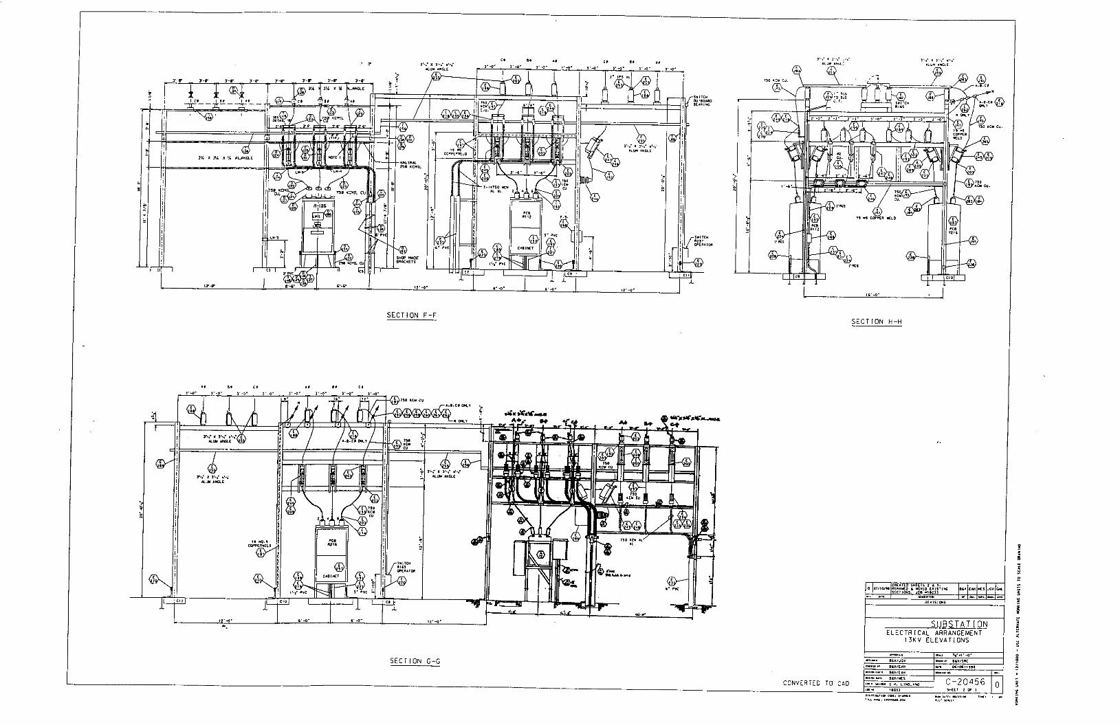
S U B S T A T I O N E L E C T R I C A L ARRANGEMENT ~
1 3 k V E L E V A T I O N S
I I ... q - I-
E L E V A T I O N D-D
E L E V A T I O N E-E
F-4 I
$
I
x
n
P
REFERFNCES CII6I

- -
FOR CONTINUATICN SEE OWG C - 1 1 9 8 9 S d T . 1 FOR CONTINUATION
SEE OWG C-11989 S H T . l
I
I
I
I
I
I
I
I
. I
4
r l - l . 1 5 0 U " U MOLALLA- I
YODER 13kV I
I I
,150 YCY -
E: 31 0,
7 3 '
I I - CAP 3 i . 4 3ANK
I 1- I
I I I I
I I
,.'-'e ! 3 ' 4 - , 1 2 . 4 -
I 1 2 ' 4 . 1 2 . 4 .
I I J-I.1sO Y Y rv ,I.
I I I ip I I
7 1 N q A), E $ C)
MOLALLA- MAROUAM l 3 k V
MOL ALL A- FORREST 13kV
1 MOLALLA-
BUCKAROO 13kV
I I
I I
-.
.%O-
.oz I
I .-
. I I"
0 a
U
0
c 0
111 l-
(L
W
5 z
0
V

Attachment D Civil Construction Cost Estimate, H3200
1 2
The following table lists the estimated costs of the civil construction. This includes the grading of the station for drainage, foundations, ground grid installation, conduit and feeder raceway installation, installation of the oil containment system for the transformer, and installation of the crushed rock surface on the station. The cost for this construction may vary depending of the detailed design of the station as required to accommodate site conditions and the exact station layout. There would probably be three or more subcontractors involved in this construction (concrete, grading and crushed rock, fence, and perhaps another for the oil containment system). The entire below grade construction should take approximately eight weeks. Foundation estimates assume slab and pier foundation types, and is based on an installed cost of USD 600/cubic yard (cy) of concrete.
In USD In USD 138 kV H-Frame Foundations, 5 cy ea 4 3,000 12,000 138 kV Circuit Switcher Foundations, 6 ’ 1,200 7,200
Item I Equipment 1 Quant. I Unit Cost I Total Cost
4
5
6 7 8
138 kV Three Phase Bus Support 4 1,200 4,800 Foundations. 2 cy ea 138 kV Single Phase Bus Support 2 1,200 2,400 Foundations, 2 cy ea 138 kV CVT Pedestal Foundation, 2 cy ea 2 1,200 2,400 Transformer Foundation, 15 cy 1 9,000 9,000 Station Service Transformers Foundations, 1 2,000 2,000 urecast with vault
I I 2 cv ea I I I
9
10 1 1
~~ ~ - .. I I I I 3 I 138 kV Switch Stand Foundations. 2 cv ea I 10 I 1.200 I 12.000
Distribution Box Structure Foundations, 8 1 ;200 9,600 2 cy ea Control Enclosure Foundation, 15 cy 1 9,000 9,000 Install Ground Grid and Equipment Stingers, 1,000 45/meter 45,000
12 meters
25,000 Install Conduits for control cables, feeder
13
14
15 16
getaways, and station service primary cables
inches of 3000 Ohm-Meter crushed rock Install layer of Geo-Textile Material and 4
Fence, two equipment gates, including all 260 Approx 12,000
Site Grading 10,000
625 cy rock, 20,000 - 50,000 sq ft
material
ground connections meters 4 5 /meter Transformer oil containment system 1 75,000
Total for all civil work USD 257,400
1 1 21 I 4/00

I 1 I I I
Item
1
2
Attachment E Electrical Construction Cost Estimate, H3500
Equipment/S ystem Labor Material Cost Total Cost Hours In USD In USD
138 kV Circuit Switchers, Disconnect 1050 50,000 125,000 Switches, CVTs, Buswork, Conductors and Power Transformer jumpers and
Assembly of 25 kV Box Structure 1200 50,000 140,000
(bus, insulators,
fittings)
The costs in the following table are for the above ground construction, predominately carried out by the electrical construction trades. The material costs shown are in addition to the costs of the equipment listed in attachment F. The burdened cost for all labor is assumed to be USD 75hour. This includes salary, labor burden, tools and construction equipment.
installing all conductors and making all grounding connections
sformers and o alternate S S Xfmr)
1
4 Control Enclosure, Control Wiring, Testing Support, etc.
It will take approximately 12 weeks of electrical construction for the station to be ready for testing and energization.
jumpers and I
fittings)
Cable)
cable)
40 5,000 (25 kV 8,000
250 10,000 (control 30,000
I Including mounting all equipment, I 1 (bus, insulators, I
I 1 21 14/00

Attachment F Equipment Cost Estimate, M3510, M3591
Item
1 2 3
The following table lists the expected equipment costs. All equipment would be purchased F.O.B. site. The transformer would be purchased F.O.B. site with delivery to the foundation, dressed and tested by the manufacturer.
Equipment Quant. Unit Cost Total Cost In USD In USD
138 kV Circuit Switchers 3 45,000 135,000 138 kV Disconnect Switches, TPST 7 6,000 42,000 138 kVCVTs 2 4.000 8 -000
4 5 6 7 8
9
~
Transformer 1 475,000 475,000
25 kV Hookstick Switches, SPST 33 400 1 3,200 25 kV Gang Operated Switch, TPST 2 4,000 8,000 25 kV Fuses (S&C SMD-20 or equal), single 6 1,000 6,000 pole Station Service Transformers. 50 kVA 2 2 .ooo 4.000
Feeder Breakers, with protection and controls 4 30,000 120,000
Voltage Transformers, single phase, 25 kV I 19000 I class 11 -
3.000
Control Enclosure including AC and DC 1 150,000 150,000 - Panels, AC Autotransfer Switch, Battery
' 12 13
Line Soctionalizing Control Panel 1 10,000 10,000 Transformei Protection Panel 1 15.000 15.000
~
16 Steel Structures 1.25/LB H-Frame Structures for landing 138 kV lines, 2 10,000 20,000
17
includes mounting of one 138 kV Disconnect Switch, 8,000 LB ea 138 kV Switch Stands. 1.200 LB ea 5 1 S O 0 7.500
L:\wp233\BCHAttachFEquiprnent
18
19 20
1 21 1 4/00
138 kV Three Phase Bus Support, 2 1,500 3,000 1,200 LB ea 138 kV Single Phase Bus Support, 500 LB ea 2 625 1,300 Distribution Box Structure, Three Bays, 1 18,750 18,750 15,000 LB ea Subtotal for steel, USD 50,550 Subtotal for all equipment 1,057,750 12% MarkupKontingency 126,930-" Total USD 1,184,680

Appendix 7
Black & Veatch Corporation Submission - Summary of Internal Comments

Appendix 7 B&V Corporation Submission - Summary of Internal Comments
Appendix 7 Black & Veatch Corporation Submission -
Summary of Internal Comments
1. STATION DESIGN (B&V responses shown in Italics)
Drawing C-20456 shows that current transformers and disconnect switches are mounted directly over the two 13 kV main buses. This type of layout will require that both buses be taken out of service during equipment servicing and replacement in order to comply with BC Hydro safety practices regulations.
The disconnect switches or current transformers could be moved to one side or the other to make maintenance easier, but since they are normally low maintenance items, this has not been a concern. However, the user of this station has indicated that to undertake the full maintenance work required a full station outage is required.
0 The same two main buses are too close to each other for 25 kV. To comply with BC Hydro’s limit of approach, work such as insulator replacement, on one set of buses requires the other set be de-energized which would result in a complete station outage.
Correct, even for the user of the station, but it is a rare event.
0 Because B&V design does not have a transfer bus, any work done on the one and only tie switch will require a complete station outage.
Agreed, but not for isolation.
0 Drawing C-20456 shows that feeder disconnects are not group operated. Although infrequent, we sometimes need to open three phases of a disconnect switch simultaneously under load during load transfer operations.
Station user did not require three-phase opening under load, but ganged switches would be used if they were.
0 The distance between the closest two power transformer bushings appears to be less than 55 feet, thus a firehlast wall is required to separate the transformers.
Correct, but the station user specified this distance.

Aovendix 7 B&V Corporation Submission - Summary of Internal Comments
I 1: I I
2.
0 For seismic reasons BC Hydro design uses cable rather than rigid bus connections to transformer and other equipment bushings.
Has not been a problem, but there is an expansion coupling at the transformer that is good for movement in the same axis as the bus. No seismic connection used.
0 Control building layout is not included in the subject report. It would be valuable to understand what B&V’s design would provide in areas of lighting, H&V, battery system, panel types and configurations, cable routing and personnel access.
Correct, no information presented in the report. However, from the site visits it was seen that B&V has little experience in this area and that the station user normally specifies this.
0 Lightning protection for equipment and bus work is not shown on the drawings. BC Hydro design uses overhead wire for shielding (A.M. Mousa method).
Correct, no information presented in the report because user of station normally specifies, but from the site visits, it was seen to be very minimum using spires and surge arresters only.
0 It appears from the drawings that no vehicular access is provided to areas between the transformers.
From the site visit it was evident this item is not a problem.
0 Details of the 115 kV switchyard are not found in the subject report.
Correct, no information presented in report because B&V’s design is not that much diflerent than BC Hydro’s.
P&C COMMENTS (B&V responses shown in Italics)
Local Control and Display:
The use of an MMI was not mentioned. It appears that conventional local control will be distributed to the various P&C panels, thus eliminating one panel containing the MMI and DC-AC inverter.
The MMI is to be replaced with an equivalent PLC and local computer, thus eliminating one panel, but room for the computer will be required.
0 There was no mention of a local display for alarms and metering information. It is assumed that Bitronics meters and SEL relays will handle the metering display function.
Assumption is correct.
A 7 - 2

Appendix 7 B&V Corporation Submission - Summary of Internal Comments
Protection:
0 The relays shown on the one-line (Drawing C-26570 Sheet 1) do not match the protection described in the report. Differences were found on the transformer and feeder bus protections. The one-line shows the use of primary and standby SELSOls that are simple over-current relays. The one-line does not show differential or bus protection relays. BC Hydro typically applies SEL35 1 s for standby protection on smaller MVA transformers and feeder bus protections.
Observation is correct. Drawing shown as an example only.
0 The report does not make specific reference to both primary and standby transformer protection. Since only one transformer differential protection is discussed, it is assumed that a standby transformer protection will not be supplied.
Over-current and dijjferential protection would be supplied and standby protection is not, but would be ifrequested.
0 The report also calls for the transformer and feeder bus protection relays to be mounted in the same panel. BC Hydro’s practice is to separate these protections for increased security.
No problems to date with arrangement.
0 With regards to feeder protection, mounting the relays in the circuit breaker cabinet will reduce both the amount of cabling and the number of PLC YO boards required in the control building.
Agreed, but the control switch would be installed in the control building.
The proposed high voltage line arrangement and protection operation is innovative. B&V propose to use a PLC in a protective function to open and close circuit switchers based on the presence of voltage.
No reply required.
SCADA:
B&V are not proposing to install a traditional RTU but will use a PLC with a protocol converter.
Correct, no reply required.

Appendix 7 B&V Corporation Submission - Summary of Internal Comments
General:
The report mentions a 19-inch rack. It should be clarified if B&V will supply a panel to BC Hydro’s standards or a simple 19-inch industrial rack without side steel.
A simple 19-inch industrial rack without steel sides would be used unless one with sides is requested.
3. REGIONAL PLANNING COMMENTS (B&V responses shown in Italics)
0 The proposed two 138 kV line circuit switchers are not required for this application. For the initial one transformer arrangement, the station is supplied via a transmission line tap and 1D21 from one line and 1D22 is Normal Open. In case of a transmission line outage 1D1 opens and 1D2 closes automatically and substation is re-energized via the tap from the second line.
Correct, but what about a bus fault on lB1 or lB2. B&V’s arrangement deals with this possibility whereas BC Hydro would accept the higher risk due to the sensitivity of the customer in this area to outages and the availability of a mobile.
The issue of using current limiting reactors was addressed a number of times (latest in 1997) and it was concluded that there are a number of good reasons to continue with our current practice:
> Standard transformer impedance permit transformers to be relocated to other stations if their capacity is exceeded or as a replacement of the failed transformer (hard to change horses mid-stream also).
> The feature of operating transformers in parallel to avoid outage in case of transformer or line outage as a solution to improve service to customers demanding uninterrupted service. However, we are not installing reactors if this secure service is not required. Normally, T1 and T2 transformers are supplying their own load but on loss of one transformer or line, automatic LV transfer is initiated and remaining transformer will pick up all load.
P The additional cost for this provision is negligible due to its location above circuit breaker and it has no effect on substation size.
> BC Hydro practice is to guarantee 300 MVA maximum fault level outside of the station to our customers and for selection of the distribution equipment.
The need for standard transformer impedance is understood as is operating transformers in parallel to improve customer services in case of an outage .But it is not agreed the reactors do not increase the size of the station and it is felt they do add to the station life-cycle cost. However, the requirement to guarantee a 300 MVA maximum fault level outside the station on the feeders appears to be a sufJicient reason to have the reactors installed. B&V have not seen this requirement before.
A7 - 4

Auvendix 7 B&V Comoration Submission - Summarv of Internal Comments
The transfer bus is a very important facility for us to allow proper maintenance of all substation equipment and bus without prolonged planned outages to our customers. For example, our existing arrangement allows us to transfer all load from one main bus section to do maintenance on bus and disconnect switches while maintaining service to all customers. Proposed arrangement does not have acceptable flexibility to maintain the same level of service.
The proposed arrangement provides some of the same flexibility, as the one BC Hydro uses for feeder coverage, but not for main bus or its equipment maintenance or repair. A full station outage would be required for this.
Have to review the use of un-ganged disconnect switches which may be a safety concern.
Station user (PG&E) did not require three-phase opening under load, but ganged switch would be used if it were.
Since we are using the feeder tie circuit breaker for capacitor bank switching, I do not see the improvement in the proposed use of combination of fuses and vacuum switches for switching of the capacitor banks. Use of fuses will create problem associated with one phase tripping.
Systems appear equivalent.
It was assumed transformer overload is only 20%. Since we are using much larger overload on our transformers (minimum 33%) the bus have to be sized accordingly.
Assuming the ultimate transformer sizes will be 50 MVA, the proposed bus work is still marginally acceptable, but fault levels and corona have not been looked at.
0 We will use and are actually using metal-clad switchgear if we can accomplish overall cost saving without compromise for safety to our maintenance people.
No reply needed.
A 7 - 5

Appendix 8
BC Hydro Internal Presentation Overheads

U I 1 I I I n I
5 II I I I I I I I
TDE Distribution Substation Cost Comparison Study
August 2001
Prepared by: Walter Brunner Bob Stewart Dave Thomas
Revised August 31, 2001
T & 0 ENGINEERING Distribution Substation Cost Comparison Study
PURPOSE OF THE STUbY:
To benchmark TDE's cost o f providing substation infrastructure with that of others in the public and private sectors.
2

T & D ENGINEERING Distribution Substat ion Cost Comparison Study
PARTICIPANTS IN THE STUDY:
BC Hydro T O Engineering Black & Veatch Corporation Oregon Office Manitoba Hydro Transmission Planning
& Design Division
3
T & D ENGINEERING Distribution Substation Cost Comparison Study
BASES OF COMPARISON:
Black & Veatch and Manitoba Hydro were asked t o provide a conceptual design and cost estimate based on the following:
+ the Qualicum Substation One Line and Specification Sheet
+ the boundary o f the study being one meter outside the (Initial and Ultimate)
substation fence
Costs included all material and equipment, all engineering, design, project management, construction management and inspection and installation.
Costs excluded were owner costs such as planning, public consultation, permitting and environmental compensations.
4
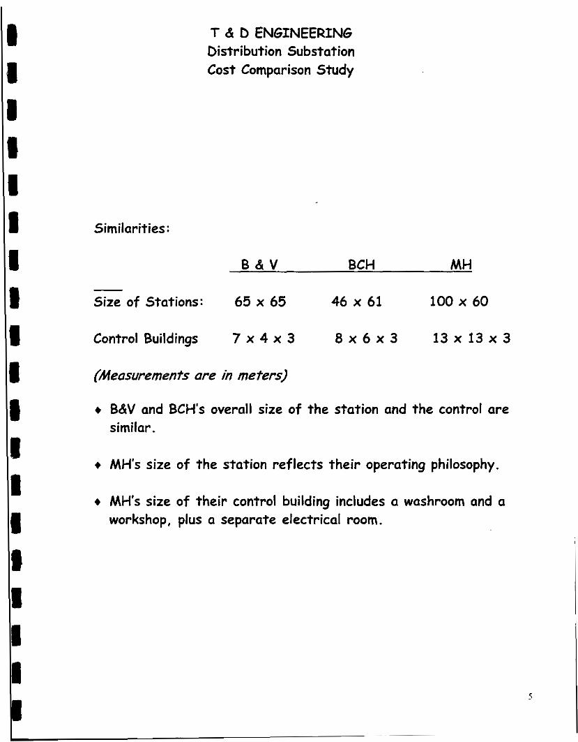
T & 0 ENGINEERING Oistr i but ion Substation Cost Comparison Study
Similarities :
B & V BCH MH
Size of Stations : 65 x 65 46 x 61 100 x 60
Control Buildings 7 X 4 X 3 8 x 6 ~ 3 13 x 13 x 3
(Measurementr are in meters)
+ B&V and BCH's overall size o f the station and the control are similar.
+ MH's size of the station reflects their operating philosophy.
+ MH's size of their control building includes a washroom and a workshop, plus a separate electrical room.
5

e 1 1
T & 0 ENGINEERING Oistri but ion Substat ion Cost Comparison Study
COMPARISON OF SUBSTATION COSTS ($K): I I I
B&V MH - BCH1 BCH2 (Actual) (Estimate)
1 Engineering & Project 263 466 469 328 Management
Construction 183 W/ 147 147 Contract Management installation
1
). Civil Work 376 321 278 278
I Electrical Work 443 276 247 247
Testing & Commissioning 1 44 140 146 146
Electrical Equipment 1658 1966 1308 1308 I E 1 TOTAL
74 W/ 81 81 equipment
3041 3169 2676 2535
I I 8 6

T & D ENGINEERING Distribution Substation Cost Comparison Study
COMPARISON OF SUBSTATION COST ($K) cont'd
OTHER PROJECT RELATED COSTS (BCH Actual $K):
Planning 30
Transmission Line Work 79
Public Consulting & Property Issues 116
Environmental Work 120
Regional Work 6
Overhead & IDC 803
TOTAL 1 1 5 4
These costs represent 30% o f the overall project costs.
7
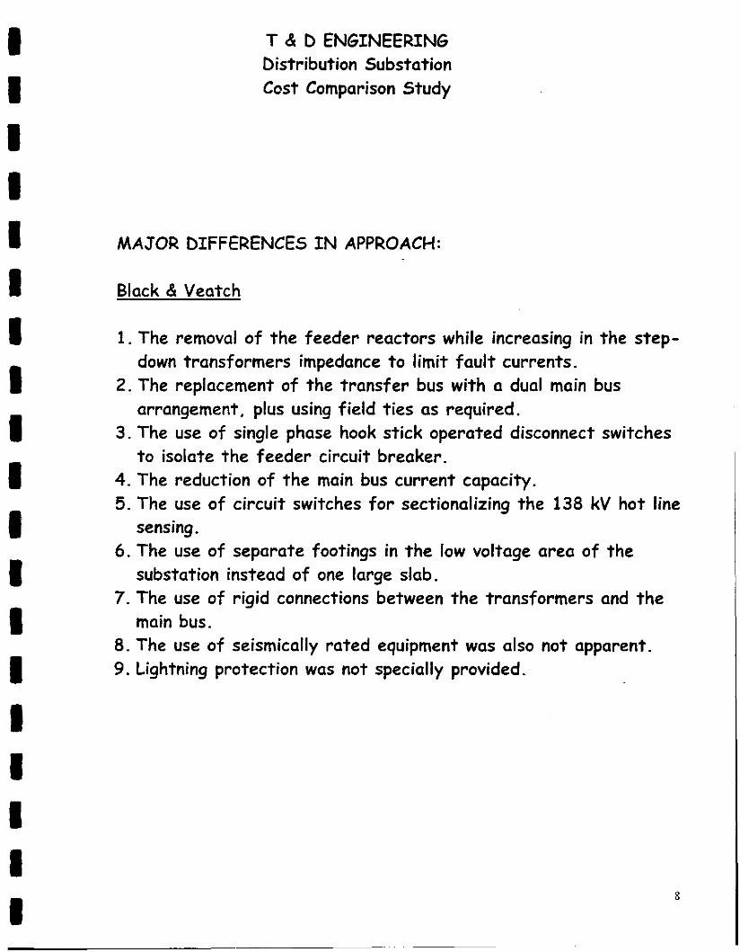
T & D ENGINEERING Distribution Substation Cost Comparison Study
MAJOR DIFFERENCES I N APPROACH:
Black & Veatch
1. The removal of the feeder reactors while increasing in the step-
2. The replacement of the transfer bus with a dual main bus
3. The use of single phase hook stick operated disconnect switches
4. The reduction of the main bus current capacity. 5. The use of circuit switches for sectionalizing the 138 kV hot line
6. The use of separate footings in the low voltage area o f the
7. The use of rigid connections between the transformers and the
8. The use of seismically rated equipment was also not apparent. 9. Lightning protection was not specially provided.
down transformers impedance t o limit fault currents.
arrangement, plus using field ties as required.
t o isolate the feeder circuit breaker.
sensing.
substation instead o f one large slab.
main bus.
8

I 1 i 1 I 1 1 I 1 I 8 8 I I 1 1 I 8 8
T & D ENGINEERING Distribution Substation Cost Comparison Study
MAJOR DIFFERENCES I N APPROACH - cont'd
Manitoba Hydro
1. The removal of the feeder reactors while increasing the step-
2. The replacement of the transfer bus wi th a dual main bus down transformers impedance t o limit fault currents.
arrangement, plus having the loads fed from separate sources, Le. two substations.
equipment, Le. lower limit increased to -50°C from -40°C.
1 ine trucks during maintenance activities.
workshop in the control building.
3. Specifying a larger temperature range required f o r the
4. The need for more working area around equipment due to use o f
5. The inclusion of a washroom, a separate electrical room and a
9

T & D ENGINEERING Distribution Substation Cost Comparison Study
DISCUSSIONS O N COST COMPARISON:
Black & Veatch
1. Black & Veatch's costs are cost estimates while BC Hydro's are actual cost.
2. Black & Veatch's engineering costs are approximately $200,000 lower than BC Hydro's mainly due t o the use of a design they have built previously, while BC Hydro's actual costs were based on a more complex prototype design, i.e. no drawings existed.
3. Black & Veatch's costs also do not include owner costs including the owner's consultant interfacing costs.
4. Black & Veatch's commissioning and testing costs seem low. 5. Black & Veatch have also included a 12% mark-up on the
electrical equipment purchased as a contingency for market fluctuations and delivery problems.
manufacturer for design, thus further reducing direct design costs.
7. Black & Veatch's Construction Manager is also responsible #or minor design changes, which also helps reduces direct design costs.
6. Black & Veatch placed greater emphasis on the equipment
I O

D I I I I I I I I I I I I I I 1 I 8 I
T & D ENGINEERING Distribution Substation Cost Comparison Study
DISCUSSIONS ON COST COMPARISON - cont'd
Manitoba Hydro
1. Manitoba Hydro's costs are cost estimates while BC Hydro's are actual costs.
2. Manitoba Hydro's construction and installation costs are higher due t o a larger sized station and use of internal construction forces .
3. Manitoba Hydro's equipment costs are higher due t o the requirement for lower ambient temperature operation, i.e. 50°C

T & D ENGINEERING Distribution Substation Cost Comparison Study
CONCLUSIONS :
1. BC Hydro's cost t o design and construct a substation using i t s traditional project delivery processes compare favorably t o others in the survey, both in the public and private sectors.
similarities. The substation sizes and building were comparable, wi th Manitoba being the largest.
3. Areas were identified where potentially further cost reduction can be achieved. This wil l require changes in our approach t o the planning, design, as well as some operation and maintenance practices and procedures.
4. Thirty percent of BC Hydro's overall project cost is associated with activities other than those directly associated wi th the design and building of a substation.
substation provides greater operation and maintenance flexibility and a higher level of reliability.
2. The basic approach of all three agencies had a number of
5. BC Hydro's approach t o the design and development o f a

I 1 I I I I I I I I I I I I I 1 I I I
T & 0 ENGINEERING bistribution Substation Cost Comparison Study
RECOMMENDATfONS:
1. A review of the use of feeder reactors should be undertaken from a T&D point of view, not just from a substation design perspective.
2. Standardization of substation One Line and design should be undertaken whenever possible.
3. The possible use of different design concepts and ideas such as using aluminum angles for buswork and using standard sideless P&C racks should be explored more fully.
4. Continue t o focus on driving down total costs, while increasing efficiency and productivity.
5. Continue t o contact others in the industry on a regular basis t o keep abreast of new ideas, concepts and different ways o f doing business.