Embed Size (px)
Citation preview

7/23/2019 Baystack 450
http://slidepdf.com/reader/full/baystack-450 1/399
Software Release V4.0.0
Part No. 309978-D Rev 01
January 2006
4655 Great America Parkway
Santa Clara, CA 95054
Using the BayStack 45010/100/1000 Series Switch

7/23/2019 Baystack 450
http://slidepdf.com/reader/full/baystack-450 2/399
ii 309978-D Rev 01
Copyright © 2001 Nortel Networks
All rights reserved. January 2006.
The information in this document is subject to change without notice. The statements, configurations, technical data,and recommendations in this document are believed to be accurate and reliable, but are presented without express or implied warranty. Users must take full responsibility for their applications of any products specified in this document.The information in this document is proprietary to Nortel Networks Inc.
Trademarks
NORTEL NETWORKS is a trademark of Nortel Networks Inc.
Accelar, BayStack, Bay Networks, Centillion, EZ LAN, Optivity, Optivity Campus, Optivity Enterprise, StackProbe,
and the Bay Networks logo are trademarks of Nortel Networks Inc.Microsoft, MS, MS-DOS, Win32, Windows, and Windows NT are trademarks of Microsoft Corporation.
All other trademarks are the property of their respective owners.
Statement of Conditions
In the interest of improving internal design, operational function, and/or reliability, Nortel Networks Inc. reserves theright to make changes to the products described in this document without notice.
Nortel Networks Inc. does not assume any liability that may occur due to the use or application of the product(s) or
circuit layout(s) described herein.
USA Requirements Only
Federal Communications Commission (FCC) Compliance Notice: Radio Frequency Notice
Note: This equipment has been tested and found to comply with the limits for a Class A digital device, pursuant toPart 15 of the FCC rules. These limits are designed to provide reasonable protection against harmful interferencewhen the equipment is operated in a commercial environment. This equipment generates, uses, and can radiate radiofrequency energy. If it is not installed and used in accordance with the instruction manual, it may cause harmful
interference to radio communications. Operation of this equipment in a residential area is likely to cause harmfulinterference, in which case users will be required to take whatever measures may be necessary to correct theinterference at their own expense.
European Requirements Only
EN 55 022 Statement
This is to certify that the Nortel Networks BayStack 450 switch is shielded against the generation of radio interferencein accordance with the application of Council Directive 89/336/EEC, Article 4a. Conformity is declared by theapplication of EN 55 022 Class A (CISPR 22).
Warning: This is a Class A product. In a domestic environment, this product may cause radio interference, in whichcase, the user may be required to take appropriate measures.
Achtung: Dieses ist ein Gerät der Funkstörgrenzwertklasse A. In Wohnbereichen können bei Betrieb dieses GerätesRundfunkstörungen auftreten, in welchen Fällen der Benutzer für entsprechende Gegenmaßnahmen verantwortlichist.
Attention: Ceci est un produit de Classe A. Dans un environnement domestique, ce produit risque de créer desinterférences radioélectriques, il appartiendra alors à l’utilisateur de prendre les mesures spécifiques appropriées.

7/23/2019 Baystack 450
http://slidepdf.com/reader/full/baystack-450 3/399
309978-D Rev 01 iii
EC Declaration of Conformity
This product conforms (or these products conform) to the provisions of Council Directive 89/336/EEC and 73/23/EEC. Go to http://libra2.corpwest.baynetworks.com/cgi-bin/ndCGI.exe/DocView/ on the Nortel Networks
World Wide Web site for a copy of the Declaration of Conformity.
Japan/Nippon Requirements Only
Voluntary Control Council for Interference (VCCI) Statement
Voluntary Control Council for Interference (VCCI) Statement
This is a Class A product based on the standard of the Voluntary Control Council for Interference by InformationTechnology Equipment (VCCI). If this equipment is used in a domestic environment, radio disturbance may arise.When such trouble occurs, the user may be required to take corrective actions.
Taiwan Requirements
Bureau of Standards, Metrology and Inspection (BSMI) Statement
Canada Requirements Only
Canadian Department of Communications Radio Interference Regulations
This digital apparatus (BayStack 450 switch) does not exceed the Class A limits for radio-noise emissions from digitalapparatus as set out in the Radio Interference Regulations of the Canadian Department of Communications.
Règlement sur le brouillage radioélectrique du ministère des Communications
Cet appareil numérique (BayStack 450 switch) respecte les limites de bruits radioélectriques visant les appareilsnumériques de classe A prescrites dans le Règlement sur le brouillage radioélectrique du ministère desCommunications du Canada.

7/23/2019 Baystack 450
http://slidepdf.com/reader/full/baystack-450 4/399
iv 309978-D Rev 01
Nortel Networks Inc. Software License Agreement
NOTICE: Please carefully read this license agreement before copying or using the accompanying software orinstalling the hardware unit with pre-enabled software (each of which is referred to as “Software” in this Agreement).
BY COPYING OR USING THE SOFTWARE, YOU ACCEPT ALL OF THE TERMS AND CONDITIONS OFTHIS LICENSE AGREEMENT. THE TERMS EXPRESSED IN THIS AGREEMENT ARE THE ONLY TERMSUNDER WHICH NORTEL NETWORKS WILL PERMIT YOU TO USE THE SOFTWARE. If you do not acceptthese terms and conditions, return the product, unused and in the original shipping container, within 30 days of purchase to obtain a credit for the full purchase price.
1. License Grant. Nortel Networks Inc. (“Nortel Networks”) grants the end user of the Software (“Licensee”) apersonal, nonexclusive, nontransferable license: a) to use the Software either on a single computer or, if applicable, ona single authorized device identified by host ID, for which it was originally acquired; b) to copy the Software solelyfor backup purposes in support of authorized use of the Software; and c) to use and copy the associated user manual
solely in support of authorized use of the Software by Licensee. This license applies to the Software only and does notextend to Nortel Networks Agent software or other Nortel Networks software products. Nortel Networks Agentsoftware or other Nortel Networks software products are licensed for use under the terms of the applicable NortelNetworks Inc. Software License Agreement that accompanies such software and upon payment by the end user of theapplicable license fees for such software.
2. Restrictions on use; reservation of rights. The Software and user manuals are protected under copyright laws.Nortel Networks and/or its licensors retain all title and ownership in both the Software and user manuals, includingany revisions made by Nortel Networks or its licensors. The copyright notice must be reproduced and included withany copy of any portion of the Software or user manuals. Licensee may not modify, translate, decompile, disassemble,
use for any competitive analysis, reverse engineer, distribute, or create derivative works from the Software or usermanuals or any copy, in whole or in part. Except as expressly provided in this Agreement, Licensee may not copy ortransfer the Software or user manuals, in whole or in part. The Software and user manuals embody Nortel Networks’and its licensors’ confidential and proprietary intellectual property. Licensee shall not sublicense, assign, or otherwisedisclose to any third party the Software, or any information about the operation, design, performance, orimplementation of the Software and user manuals that is confidential to Nortel Networks and its licensors; however,Licensee may grant permission to its consultants, subcontractors, and agents to use the Software at Licensee’s facility,provided they have agreed to use the Software only in accordance with the terms of this license.
3. Limited warranty. Nortel Networks warrants each item of Software, as delivered by Nortel Networks and properly
installed and operated on Nortel Networks hardware or other equipment it is originally licensed for, to functionsubstantially as described in its accompanying user manual during its warranty period, which begins on the dateSoftware is first shipped to Licensee. If any item of Software fails to so function during its warranty period, as the soleremedy Nortel Networks will at its discretion provide a suitable fix, patch, or workaround for the problem that may beincluded in a future Software release. Nortel Networks further warrants to Licensee that the media on which theSoftware is provided will be free from defects in materials and workmanship under normal use for a period of 90 daysfrom the date Software is first shipped to Licensee. Nortel Networks will replace defective media at no charge if it isreturned to Nortel Networks during the warranty period along with proof of the date of shipment. This warranty doesnot apply if the media has been damaged as a result of accident, misuse, or abuse. The Licensee assumes allresponsibility for selection of the Software to achieve Licensee’s intended results and for the installation, use, and
results obtained from the Software. Nortel Networks does not warrant a) that the functions contained in the softwarewill meet the Licensee’s requirements, b) that the Software will operate in the hardware or software combinations thatthe Licensee may select, c) that the operation of the Software will be uninterrupted or error free, or d) that all defectsin the operation of the Software will be corrected. Nortel Networks is not obligated to remedy any Software defect thatcannot be reproduced with the latest Software release. These warranties do not apply to the Software if it has been (i)altered, except by Nortel Networks or in accordance with its instructions; (ii) used in conjunction with anothervendor’s product, resulting in the defect; or (iii) damaged by improper environment, abuse, misuse, accident, ornegligence. THE FOREGOING WARRANTIES AND LIMITATIONS ARE EXCLUSIVE REMEDIES AND AREIN LIEU OF ALL OTHER WARRANTIES EXPRESS OR IMPLIED, INCLUDING WITHOUT LIMITATION ANY
WARRANTY OF MERCHANTABILITY OR FITNESS FOR A PARTICULAR PURPOSE.

7/23/2019 Baystack 450
http://slidepdf.com/reader/full/baystack-450 5/399
309978-D Rev 01 v
Licensee is responsible for the security of its own data and information and for maintaining adequate procedures apartfrom the Software to reconstruct lost or altered files, data, or programs.
4. Limitation of liability. IN NO EVENT WILL NORTEL NETWORKS OR ITS LICENSORS BE LIABLE FOR
ANY COST OF SUBSTITUTE PROCUREMENT; SPECIAL, INDIRECT, INCIDENTAL, OR CONSEQUENTIALDAMAGES; OR ANY DAMAGES RESULTING FROM INACCURATE OR LOST DATA OR LOSS OF USE ORPROFITS ARISING OUT OF OR IN CONNECTION WITH THE PERFORMANCE OF THE SOFTWARE, EVENIF NORTEL NETWORKS HAS BEEN ADVISED OF THE POSSIBILITY OF SUCH DAMAGES. IN NO EVENTSHALL THE LIABILITY OF NORTEL NETWORKS RELATING TO THE SOFTWARE OR THIS AGREEMENTEXCEED THE PRICE PAID TO NORTEL NETWORKS FOR THE SOFTWARE LICENSE.
5. Government Licensees. This provision applies to all Software and documentation acquired directly or indirectlyby or on behalf of the United States Government. The Software and documentation are commercial products, licensedon the open market at market prices, and were developed entirely at private expense and without the use of any U.S.
Government funds. The license to the U.S. Government is granted only with restricted rights, and use, duplication, ordisclosure by the U.S. Government is subject to the restrictions set forth in subparagraph (c)(1) of the CommercialComputer Software––Restricted Rights clause of FAR 52.227-19 and the limitations set out in this license for civilianagencies, and subparagraph (c)(1)(ii) of the Rights in Technical Data and Computer Software clause of DFARS252.227-7013, for agencies of the Department of Defense or their successors, whichever is applicable.
6. Use of Software in the European Community. This provision applies to all Software acquired for use within theEuropean Community. If Licensee uses the Software within a country in the European Community, the SoftwareDirective enacted by the Council of European Communities Directive dated 14 May, 1991, will apply to theexamination of the Software to facilitate interoperability. Licensee agrees to notify Nortel Networks of any such
intended examination of the Software and may procure support and assistance from Nortel Networks.7. Term and termination. This license is effective until terminated; however, all of the restrictions with respect toNortel Networks’ copyright in the Software and user manuals will cease being effective at the date of expiration of theNortel Networks copyright; those restrictions relating to use and disclosure of Nortel Networks’ confidentialinformation shall continue in effect. Licensee may terminate this license at any time. The license will automaticallyterminate if Licensee fails to comply with any of the terms and conditions of the license. Upon termination for anyreason, Licensee will immediately destroy or return to Nortel Networks the Software, user manuals, and all copies.Nortel Networks is not liable to Licensee for damages in any form solely by reason of the termination of this license.
8. Export and Re-export. Licensee agrees not to export, directly or indirectly, the Software or related technical data
or information without first obtaining any required export licenses or other governmental approvals. Without limitingthe foregoing, Licensee, on behalf of itself and its subsidiaries and affiliates, agrees that it will not, without firstobtaining all export licenses and approvals required by the U.S. Government: (i) export, re-export, transfer, or divertany such Software or technical data, or any direct product thereof, to any country to which such exports or re-exportsare restricted or embargoed under United States export control laws and regulations, or to any national or resident of such restricted or embargoed countries; or (ii) provide the Software or related technical data or information to anymilitary end user or for any military end use, including the design, development, or production of any chemical,nuclear, or biological weapons.
9. General. If any provision of this Agreement is held to be invalid or unenforceable by a court of competent jurisdiction, the remainder of the provisions of this Agreement shall remain in full force and effect. This Agreementwill be governed by the laws of the state of California.
Should you have any questions concerning this Agreement, contact Nortel Networks, 2375 N. Glenville Dr.,Richardson, TX 75082.
LICENSEE ACKNOWLEDGES THAT LICENSEE HAS READ THIS AGREEMENT, UNDERSTANDS IT, ANDAGREES TO BE BOUND BY ITS TERMS AND CONDITIONS. LICENSEE FURTHER AGREES THAT THISAGREEMENT IS THE ENTIRE AND EXCLUSIVE AGREEMENT BETWEEN NORTEL NETWORKS ANDLICENSEE, WHICH SUPERSEDES ALL PRIOR ORAL AND WRITTEN AGREEMENTS ANDCOMMUNICATIONS BETWEEN THE PARTIES PERTAINING TO THE SUBJECT MATTER OF THISAGREEMENT. NO DIFFERENT OR ADDITIONAL TERMS WILL BE ENFORCEABLE AGAINST NORTEL
NETWORKS UNLESS NORTEL NETWORKS GIVES ITS EXPRESS WRITTEN CONSENT, INCLUDING ANEXPRESS WAIVER OF THE TERMS OF THIS AGREEMENT.

7/23/2019 Baystack 450
http://slidepdf.com/reader/full/baystack-450 6/399
7/23/2019 Baystack 450
http://slidepdf.com/reader/full/baystack-450 7/399
309978-D Rev 01 vii
Contents
Preface
Audience ........................................................................................................................ xxv
Organization ................................................................................................................. xxviText Conventions ......................................................................................................... xxvii
Acronyms .................................................................................................................... xxviii
Related Publications ...................................................................................................... xxx
How to Get Help ........................................................................................................... xxxi
Chapter 1
BayStack 450 10/100/1000 Series SwitchesPhysical Description .......................................................................................................1-2
Front Panel ...............................................................................................................1-2
Comm Port ........................................................................................................1-4
Uplink/Expansion Module Slot ...........................................................................1-4
10BASE-T/100BASE-TX Ports ..........................................................................1-4
100BASE-FX MT-RJ Ports .................................................................................1-5LED Display Panel .............................................................................................1-6
Back Panel .............................................................................................................1-10
AC Power Receptacle ......................................................................................1-10
Redundant Power Supply Unit (RPSU) Connector ..........................................1-12
Cascade Module Slot ......................................................................................1-12
Cooling Fans ..........................................................................................................1-13
Features ........................................................................................................................1-13
SNMP Support .............................................................................................................1-16
MIBs .......................................................................................................................1-16
SNMP Traps ...........................................................................................................1-17
Security .........................................................................................................................1-17
MAC Address-Based Security ................................................................................1-20
EAPOL-Based Security ..........................................................................................1-21

7/23/2019 Baystack 450
http://slidepdf.com/reader/full/baystack-450 8/399
viii 309978-D Rev 01
Security Example .............................................................................................1-21
Overview and Terms ........................................................................................1-23
Dynamic VLAN Assignment ............................................................................1-24Setting Up the Authentication Server ...............................................................1-25
Authentication Process ....................................................................................1-26
System Requirements .....................................................................................1-27
Configuration Rules .........................................................................................1-28
RADIUS-Based Security ........................................................................................1-28
SNMP-Based Security ...........................................................................................1-29
Flash Memory Storage .................................................................................................1-29
Switch Software Image ..........................................................................................1-29
Configuration Parameters ......................................................................................1-30
Configuration and Switch Management ........................................................................1-30
BootP Automatic IP Configuration/MAC Address .........................................................1-31
Autosensing and Autonegotiation .................................................................................1-31
Network Configurations ................................................................................................1-32
Desktop Switch Application ....................................................................................1-33
Segment Switch Application ...................................................................................1-34
High-Density Switched Workgroup Application ......................................................1-35
ATM Application .....................................................................................................1-36
Setting Up an ATM Configuration ....................................................................1-37
Fail-Safe Stack Application ....................................................................................1-38Stack Operation ............................................................................................................1-39
BayStack 400-ST1 Cascade Module .....................................................................1-41
Cascade A Out Connector ...............................................................................1-41
Unit Select Switch ............................................................................................1-41
Cascade A In Connector .................................................................................1-42
Base Unit ................................................................................................................1-43
Stack Configurations ..............................................................................................1-45
Stack Up Configurations ..................................................................................1-46
Stack Down Configurations .............................................................................1-46
Redundant Cascade Stacking Feature ..................................................................1-48
Virtual Local Area Networks (VLANs) ..........................................................................1-49
Supported VLAN Types ..........................................................................................1-50
IEEE 802.1Q VLAN Workgroups ...........................................................................1-50
7/23/2019 Baystack 450
http://slidepdf.com/reader/full/baystack-450 9/399
309978-D Rev 01 ix
IEEE 802.1Q Tagging .............................................................................................1-52
VLANs Spanning Multiple Switches .......................................................................1-58
VLANs Spanning Multiple 802.1Q Tagged Switches .......................................1-58VLANs Spanning Multiple Untagged Switches ................................................1-59
Shared Servers ......................................................................................................1-61
VLAN Workgroup Summary ...................................................................................1-67
VLAN Configuration Rules .....................................................................................1-68
IGMP Snooping ............................................................................................................1-69
IGMP Snooping Configuration Rules .....................................................................1-73
IEEE 802.1p Prioritizing ...............................................................................................1-74
MultiLink Trunks ............................................................................................................1-78
Client/Server Configuration Using MultiLink Trunks ...............................................1-79
Trunk Configuration Screen Examples ...................................................................1-81
Trunk Configuration Screen for Switch S1 .......................................................1-81
Trunk Configuration Screen for Switch S2 .......................................................1-84
Trunk Configuration Screen for Switch S3 .......................................................1-86Trunk Configuration Screen for Switch S4 .......................................................1-88
Before Configuring Trunks ......................................................................................1-90
MultiLink Trunking Configuration Rules ..................................................................1-90
How the MultiLink Trunk Reacts to Losing Distributed Trunk Members .................1-92
Spanning Tree Considerations for MultiLink Trunks ...............................................1-93
Additional Tips About the MultiLink Trunking Feature ............................................1-96Port Mirroring (Conversation Steering) .........................................................................1-97
Port-Based Mirroring Configuration ........................................................................1-98
Address-Based Mirroring Configuration ...............................................................1-100
Port Mirroring Configuration Rules .......................................................................1-103
Chapter 2
Installing the BayStack 450 SwitchInstallation Requirements ...............................................................................................2-1
Installation Procedure .....................................................................................................2-3
Installing the BayStack 450 Switch on a Flat Surface ..............................................2-3
Installing the BayStack 450 Switch in a Rack ..........................................................2-4
Attaching Devices to the BayStack 450 Switch ........................................................2-7
Connecting the 10BASE-T/100BASE-TX Ports .................................................2-8
Connecting Fiber Optic Ports ............................................................................2-9

7/23/2019 Baystack 450
http://slidepdf.com/reader/full/baystack-450 10/399
x 309978-D Rev 01
Console/Comm Port ........................................................................................2-10
Connecting a Terminal to the Console/Comm Port .........................................2-11
Connecting Power ........................................................................................................2-12Verifying the Installation ................................................................................................2-14
Verifying the Installation Using the LEDs ...............................................................2-14
Verifying the Installation Using the Self-Test Screen ..............................................2-15
Initial Setup ...................................................................................................................2-17
Standalone Switch Setup .......................................................................................2-17
Stack Setup ............................................................................................................2-20
Chapter 3Using the Console Interface
Accessing the CI Menus and Screens ............................................................................3-2
Using the CI Menus and Screens ............................................................................3-2
Navigating the CI Menus and Screens .....................................................................3-3
Map of CI Menus and Screens .................................................................................3-4
Main Menu ......................................................................................................................3-5
IP Configuration/Setup ...................................................................................................3-9
BootP Request Mode .............................................................................................3-11
BootP Disabled ................................................................................................3-12
BootP or Last Address .....................................................................................3-12
BootP When Needed .......................................................................................3-13
BootP Always ...................................................................................................3-13
SNMP Configuration .....................................................................................................3-14
System Characteristics .................................................................................................3-16
Switch Configuration .....................................................................................................3-19
MAC Address Table ................................................................................................3-22
MAC Address-Based Security ................................................................................3-24
MAC Address Security Configuration ..............................................................3-26MAC Address Security Port Configuration .......................................................3-30
MAC Address Security Port Lists .....................................................................3-33
MAC Address Security Table ...........................................................................3-37
EAPOL Security Configuration ...............................................................................3-40
VLAN Configuration Menu .....................................................................................3-44
VLAN Configuration .........................................................................................3-46
VLAN Port Configuration ................................................................................. 3-52

7/23/2019 Baystack 450
http://slidepdf.com/reader/full/baystack-450 11/399
309978-D Rev 01 xi
VLAN Display by Port ......................................................................................3-56
Traffic Class Configuration ...............................................................................3-57
Port Configuration ..................................................................................................3-59High Speed Flow Control Configuration .................................................................3-62
Choosing a High Speed Flow Control Mode ..........................................................3-63
Symmetric Mode ..............................................................................................3-64
Asymmetric Mode ............................................................................................3-64
MultiLink Trunk Configuration .................................................................................3-64
MultiLink Trunk Configuration Screen ..............................................................3-66
MultiLink Trunk Utilization Screen ....................................................................3-68
Port Mirroring Configuration ...................................................................................3-71
Rate Limiting Configuration ....................................................................................3-75
IGMP Configuration Menu ......................................................................................3-78
IGMP Configuration .........................................................................................3-79
Multicast Group Membership ...........................................................................3-83
Port Statistics .........................................................................................................3-85ATM Configuration Menu ........................................................................................3-89
Before Configuring Your ATM MDA ..................................................................3-90
LEC Configuration ...........................................................................................3-91
ATM MDA Configuration ..................................................................................3-94
ATM MDA Software Download .........................................................................3-97
Console/Comm Port Configuration .............................................................................3-100Identify Unit Numbers .................................................................................................3-107
Renumber Stack Units ................................................................................................3-107
Display Hardware Units ..............................................................................................3-109
Spanning Tree Configuration ......................................................................................3-110
Spanning Tree Port Configuration ........................................................................3-112
Display Spanning Tree Switch Settings ................................................................3-115
TELNET/SNMP Manager List Configuration ..............................................................3-118
Software Download .....................................................................................................3-121
Configuration File .......................................................................................................3-125
Display Event Log .......................................................................................................3-128
Excessive Bad Entries .........................................................................................3-129
Write Threshold ....................................................................................................3-130
Flash Update ........................................................................................................3-130

7/23/2019 Baystack 450
http://slidepdf.com/reader/full/baystack-450 12/399
xii 309978-D Rev 01
Save Current Settings .................................................................................................3-131
Reset ..........................................................................................................................3-131
Reset to Default Settings ............................................................................................3-133Logout .........................................................................................................................3-136
Chapter 4Troubleshooting
Interpreting the LEDs .....................................................................................................4-1
Diagnosing and Correcting the Problem .........................................................................4-5
Normal Power-Up Sequence ....................................................................................4-6Port Connection Problems .......................................................................................4-8
Autonegotiation Modes ......................................................................................4-8
Port Interface .....................................................................................................4-9
Software Download Error Codes ....................................................................................4-9
Appendix A
Technical SpecificationsEnvironmental ................................................................................................................ A-1
Electrical ........................................................................................................................ A-2
Physical Dimensions ...................................................................................................... A-2
Performance Specifications ........................................................................................... A-2
Network Protocol and Standards Compatibility ............................................................. A-3
Data Rate ...................................................................................................................... A-3
Interface Options ........................................................................................................... A-3
Safety Agency Certification ........................................................................................... A-4
Electromagnetic Emissions ........................................................................................... A-4
Electromagnetic Immunity ............................................................................................. A-4
Declaration of Conformity .............................................................................................. A-4
Appendix BGigabit Fiber Optical Characteristics
1000BASE-SX Models .................................................................................................. B-1
Operating Range ..................................................................................................... B-1
Transmit Characteristics .......................................................................................... B-2
Receive Characteristics .......................................................................................... B-3
Worst-Case Power Budget and Penalties ............................................................... B-3
1000BASE-LX Models ................................................................................................... B-4

7/23/2019 Baystack 450
http://slidepdf.com/reader/full/baystack-450 13/399
309978-D Rev 01 xiii
Operating Range ..................................................................................................... B-4
Transmit Characteristics .......................................................................................... B-5
Receive Characteristics .......................................................................................... B-5
Worst-Case Power Budget and Penalties ............................................................... B-6
Appendix CMedia Dependent Adapters
10BASE-T/100BASE-TX MDA ...................................................................................... C-2
100BASE-FX MDAs ....................................................................................................... C-3
1000BASE-SX MDAs .................................................................................................... C-61000BASE-LX MDAs ..................................................................................................... C-9
Asynchronous Transfer Mode (ATM) MDAs ................................................................. C-12
Gigabit Interface Converter (GBIC) MDA .................................................................... C-15
Installing an MDA ......................................................................................................... C-17
Replacing an MDA ....................................................................................................... C-19
Installing GBICs ........................................................................................................... C-19
Installation ............................................................................................................. C-20
Removing an Installed GBIC ................................................................................. C-21
1000BASE-LX Multimode Applications ....................................................................... C-22
Appendix DATM Overview
ATM Terminology ........................................................................................................... D-1
LAN Emulation (LANE) ........................................................................................... D-1
Emulated LAN (ELAN) ............................................................................................ D-3
LAN Emulation Client (LEC) .................................................................................... D-3
LAN Emulation Configuration Server (LECS) ......................................................... D-4
LAN Emulation Server (LES) .................................................................................. D-4
Broadcast and Unknown Server (BUS) ................................................................... D-4
User-to-Network Interface (UNI) ............................................................................. D-5
ATM Data Transmission ................................................................................................. D-5
Configuration Concepts ................................................................................................. D-6
ELAN VLAN Mapping .............................................................................................. D-7
Available Services ................................................................................................... D-7
LANE ................................................................................................................ D-8
UNI Support ...................................................................................................... D-8

7/23/2019 Baystack 450
http://slidepdf.com/reader/full/baystack-450 14/399
xiv 309978-D Rev 01
LECS Address Methods ................................................................................... D-8
PHY .................................................................................................................. D-8
Virtual Ports ............................................................................................................ D-9
LEC Failover .......................................................................................................... D-10
Spanning Tree on LEC VPorts .............................................................................. D-11
Configuration Rules ..................................................................................................... D-13
Mixed Stack Configurations ................................................................................... D-13
Initial Configuration ............................................................................................... D-13
Enabling a LEC ..................................................................................................... D-13
LECs and VLAN Membership ............................................................................... D-14
Console Differences .............................................................................................. D-14
Appendix EQuick Steps to Features
Configuring 802.1Q VLANs ........................................................................................... E-2
Configuring Security Settings ........................................................................................ E-5
Configuring the BayStack 450-2M3/2S3 MDAs ........................................................... E-15
Configuring MultiLink Trunks ....................................................................................... E-18
Configuring Port Mirroring ........................................................................................... E-19
Configuring IGMP Snooping ........................................................................................ E-21
Appendix FConnectors and Pin Assignments
RJ-45 (10BASE-T/100BASE-TX) Port Connectors ........................................................F-1
MDI and MDI-X Devices .................................................................................................F-2
MDI-X to MDI Cable Connections ............................................................................F-3
MDI-X to MDI-X Cable Connections ........................................................................F-4
DB-9 (RS-232-D) Console/Comm Port Connector .........................................................F-5
Appendix GDefault Settings
Appendix HSample BootP Configuration File
Index

7/23/2019 Baystack 450
http://slidepdf.com/reader/full/baystack-450 15/399
309978-D Rev 01 xv
Figures
Figure 1-1. BayStack 450 Switch Versions .................................................................2-2
Figure 1-2. BayStack 450 Switch Front Panels ..........................................................2-3
Figure 1-3. BayStack 450-24T/12T LED Display Panel ..............................................2-6Figure 1-4. BayStack 450-12F LED Display Panel .....................................................2-7
Figure 1-5. BayStack 450 Switch Back Panel ..........................................................2-10
Figure 1-6. BayStack 450 Switch Security Feature Example ...................................2-18
Figure 1-7. EAPOL-Based Security (1 of 2) .............................................................2-22
Figure 1-8. EAPOL-Based Security (2 of 2) .............................................................2-22
Figure 1-9. Authentication Process Flowchart (1 of 2) .............................................2-26
Figure 1-10. Authentication Process Flowchart (2 of 2) .............................................2-27
Figure 1-11. BayStack 450 Switch Used as a Desktop Switch ..................................2-33
Figure 1-12. BayStack 450 Switch Used as a Segment Switch .................................2-34
Figure 1-13. Configuring Power Workgroups and a Shared Media Hub ....................2-35
Figure 1-14. Configuring an ATM Application .............................................................2-36
Figure 1-15. Fail-Safe Stack Example ........................................................................2-38
Figure 1-16. Compatible Software Versions ...............................................................2-39
Figure 1-17. BayStack 400-ST1 Front-Panel Components ........................................2-41
Figure 1-18. Connecting Cascade Cables .................................................................2-42
Figure 1-19. Stack Up Configuration Example ...........................................................2-46
Figure 1-20. Stack Down Configuration Example ......................................................2-47
Figure 1-21. Redundant Cascade Stacking Feature ..................................................2-49
Figure 1-22. Port-Based VLAN Example ....................................................................2-51Figure 1-23. Default VLAN Settings ...........................................................................2-53
Figure 1-24. Port-Based VLAN Assignment ...............................................................2-54
Figure 1-25. 802.1Q Tagging (After Port-Based VLAN Assignment) .........................2-55
Figure 1-26. Protocol-Based VLAN Assignment ........................................................2-55
Figure 1-27. 802.1Q Tagging (After Protocol-Based VLAN Assignment) ...................2-56
Figure 1-28. 802.1Q Tag Assignment .........................................................................2-57
Figure 1-29. 802.1Q Tagging (After 802.1Q Tag Assignment) ...................................2-57

7/23/2019 Baystack 450
http://slidepdf.com/reader/full/baystack-450 16/399
xvi 309978-D Rev 01
Figure 1-30. VLANs Spanning Multiple 802.1Q Tagged Switches .............................2-58
Figure 1-31. VLANs Spanning Multiple Untagged Switches ......................................2-59
Figure 1-32. Possible Problems with VLANs and Spanning Tree Protocol .................2-60
Figure 1-33. Multiple VLANs Sharing Resources .......................................................2-61
Figure 1-34. VLAN Broadcast Domains Within the Switch .........................................2-62
Figure 1-35. Default VLAN Configuration Screen Example .......................................2-63
Figure 1-36. VLAN Configuration Screen Example ....................................................2-64
Figure 1-37. Default VLAN Port Configuration Screen Example ................................2-65
Figure 1-38. VLAN Port Configuration Screen Example ............................................2-66
Figure 1-39. VLAN Configuration Spanning Multiple Switches ..................................2-67
Figure 1-40. IP Multicast Propagation With IGMP Routing ........................................2-70
Figure 1-41. BayStack 450 Switch Filtering IP Multicast Streams (1 of 2) .................2-71
Figure 1-42. BayStack 450 Switch Filtering IP Multicast Streams (2 of 2) .................2-72
Figure 1-43. Prioritizing Packets .................................................................................2-74
Figure 1-44. Port Transmit Queue ..............................................................................2-75
Figure 1-45. Default Traffic Class Configuration Screen Example .............................2-76Figure 1-46. Setting Port Priority Example .................................................................2-77
Figure 1-47. Switch-to-Switch Trunk Configuration Example .....................................2-78
Figure 1-48. Switch-to-Server Trunk Configuration Example .....................................2-79
Figure 1-49. Client/Server Configuration Example .....................................................2-80
Figure 1-50. Choosing the MultiLink Trunk Configuration Screen ..............................2-81
Figure 1-51. MultiLink Trunk Configuration Screen for Switch S1 ..............................2-82
Figure 1-52. MultiLink Trunk Configuration Screen for Switch S2 ..............................2-84
Figure 1-53. MultiLink Trunk Configuration Screen for Switch S3 ..............................2-86
Figure 1-54. MultiLink Trunk Configuration Screen for Switch S4 ..............................2-88
Figure 1-55. Loss of Distributed Trunk Members .......................................................2-92
Figure 1-56. Path Cost Arbitration Example ...............................................................2-93
Figure 1-57. Example 1: Correctly Configured Trunk .................................................2-94
Figure 1-58. Example 2: Detecting a Misconfigured Port ...........................................2-95
Figure 1-59. Port-Based Mirroring Configuration Example ........................................2-98
Figure 1-60. Port Mirroring Port-Based Screen Example .........................................2-100
Figure 1-61. Address-Based Mirroring Configuration Example ................................2-101
Figure 1-62. Port Mirroring Address-Based Screen Example ..................................2-102
Figure 2-1. Package Contents ....................................................................................2-2
Figure 2-2. Positioning the Chassis in the Rack .........................................................2-5
7/23/2019 Baystack 450
http://slidepdf.com/reader/full/baystack-450 17/399
309978-D Rev 01 xvii
Figure 2-3. Attaching Mounting Brackets ...................................................................2-6
Figure 2-4. Installing the BayStack 450 Switch in an Equipment Rack ......................2-6
Figure 2-5. 10/100 Mb/s Port Connections .................................................................2-8
Figure 2-6. Fiber Optic Port Connections ...................................................................2-9
Figure 2-7. Connecting to the Console/Comm Port .................................................2-11
Figure 2-8. BayStack 450 Switch AC Power Receptacle .........................................2-13
Figure 2-9. Grounded AC Power Outlet ....................................................................2-13
Figure 2-10. Observing LEDs to Verify Proper Operation ..........................................2-14
Figure 2-11. BayStack 450 Switch Self-Test Screen ..................................................2-15
Figure 2-12. Nortel Networks Logo Screen ................................................................2-16
Figure 2-13. Main Menu for Standalone Switch .........................................................2-18
Figure 2-14. IP Configuration/Setup Screen (Standalone Switch) .............................2-19
Figure 2-15. Main Menu (Standalone Switch Example) .............................................2-21
Figure 2-16. Main Menu (Stack Configuration Example) ...........................................2-21
Figure 2-17. IP Configuration/Setup Screen (Stack Configuration) ............................2-22
Figure 3-1. Map of Console Interface Screens ...........................................................3-4Figure 3-2. Console Interface Main Menu ..................................................................3-5
Figure 3-3. IP Configuration/Setup Screen ................................................................3-9
Figure 3-4. SNMP Configuration Screen ..................................................................3-14
Figure 3-5. System Characteristics Screen ..............................................................3-16
Figure 3-6. Switch Configuration Menu ....................................................................3-19
Figure 3-7. MAC Address Table Screen ...................................................................3-22
Figure 3-8. MAC Address Security Configuration Menu ..........................................3-25
Figure 3-9. MAC Address Security Configuration Screen ........................................3-27
Figure 3-10. MAC Address Security Port Configuration (Screen 1 of 2) ....................3-30
Figure 3-11. MAC Address Security Port Configuration (Screen 2 of 2) ....................3-31
Figure 3-12. MAC Address Security Port Lists Screens (5 Screens) .........................3-33
Figure 3-13. MAC Address Security Port Lists Screen ..............................................3-34
Figure 3-14. MAC Address Security Table Screens (16 Screens) ..............................3-37
Figure 3-15. MAC Address Security Table Screen .....................................................3-38
Figure 3-16. EAPOL Security Configuration Screen ..................................................3-41
Figure 3-17. VLAN Configuration Menu .....................................................................3-45
Figure 3-18. VLAN Configuration Screen ...................................................................3-47
Figure 3-19. VLAN Port Configuration Screen ...........................................................3-53
Figure 3-20. VLAN Display by Port Screen ................................................................3-56

7/23/2019 Baystack 450
http://slidepdf.com/reader/full/baystack-450 18/399
xviii 309978-D Rev 01
Figure 3-21. Traffic Class Configuration Screen .........................................................3-58
Figure 3-22. Port Configuration Screen (1 of 2) .........................................................3-59
Figure 3-23. Port Configuration Screen (2 of 2) .........................................................3-60
Figure 3-24. High Speed Flow Control Configuration Screen ....................................3-62
Figure 3-25. MultiLink Trunk Configuration Menu .......................................................3-65
Figure 3-26. MultiLink Trunk Configuration Screen ....................................................3-67
Figure 3-27. MultiLink Trunk Utilization Screen (1 of 2) ..............................................3-69
Figure 3-28. MultiLink Trunk Utilization Screen (2 of 2) ..............................................3-70
Figure 3-29. Port Mirroring Configuration Screen ......................................................3-72
Figure 3-30. Rate Limiting Configuration Screen (1 of 2) ...........................................3-75
Figure 3-31. Rate Limiting Configuration Screen (2 of 2) ...........................................3-76
Figure 3-32. IGMP Configuration Menu .....................................................................3-78
Figure 3-33. IGMP Configuration Screen ...................................................................3-80
Figure 3-34. Multicast Group Membership Screen .....................................................3-84
Figure 3-35. Port Statistics Screen .............................................................................3-85
Figure 3-36. ATM Configuration Menu .......................................................................3-89Figure 3-37. LEC Configuration Screen .....................................................................3-92
Figure 3-38. ATM MDA Configuration Screen ............................................................3-95
Figure 3-39. ATM MDA Software Download Screen ..................................................3-98
Figure 3-40. Console/Comm Port Configuration Screen ..........................................3-100
Figure 3-41. Renumber Stack Units Screen .............................................................3-108
Figure 3-42. Hardware Unit Information Screen .......................................................3-110
Figure 3-43. Spanning Tree Configuration Menu .....................................................3-111
Figure 3-44. Spanning Tree Port Configuration Screen (1 of 2) ...............................3-112
Figure 3-45. Spanning Tree Port Configuration Screen (2 of 2) ...............................3-113
Figure 3-46. Spanning Tree Switch Settings Screen ................................................3-115
Figure 3-47. TELNET/SNMP Manager List Configuration Screen ...........................3-118
Figure 3-48. Software Download Screen .................................................................3-122
Figure 3-49. Configuration File Download/Upload Screen .......................................3-125
Figure 3-50. Event Log Screen ................................................................................3-128
Figure 3-51. Sample Event Log Entry Showing Excessive Bad Entries ...................3-129
Figure 3-52. Sample Event Log Entry Exceeding the Write Threshold ....................3-130
Figure 3-53. Sample Event Log Entry Showing Flash Update Status ......................3-130
Figure 3-54. Self-Test Screen After Resetting the Switch ........................................3-131
Figure 3-55. Nortel Networks Logo Screen ..............................................................3-132

7/23/2019 Baystack 450
http://slidepdf.com/reader/full/baystack-450 19/399
309978-D Rev 01 xix
Figure 3-56. Self-Test Screen After Resetting to Default Settings ...........................3-134
Figure 3-57. Nortel Networks Logo Screen After Resetting to Default Settings .......3-135
Figure 3-58. Password Prompt Screen ....................................................................3-136
Figure 4-1. BayStack 450-24T/12T LED Display Panels ............................................4-2
Figure 4-2. BayStack 450-12F LED Display Panel .....................................................4-3
Figure C-1. 400-4TX MDA Front Panel ......................................................................C-2
Figure C-2. 100BASE-FX MDA Front Panels .............................................................C-4
Figure C-3. 1000BASE-SX MDA Front Panels .......................................................... C-7
Figure C-4. 1000BASE-LX MDA Front Panels ......................................................... C-10
Figure C-5. ATM MDA Front Panels ......................................................................... C-13
Figure C-6. 450-1GBIC MDA Front Panel ................................................................ C-16
Figure C-7. Installing an MDA ..................................................................................C-18
Figure C-8. GBIC Case Styles ................................................................................. C-20
Figure C-9. Installing A GBIC ...................................................................................C-21
Figure C-10. Removing a GBIC ................................................................................. C-21
Figure D-1. ATM LAN Emulation Model ..................................................................... D-2Figure D-2. ATM Transmission Components .............................................................D-6
Figure D-3. ELAN VLAN Mapping ............................................................................. D-7
Figure D-4. Virtual and Physical Ports .......................................................................D-9
Figure D-5. LEC VPorts with Spanning Tree Enabled (1 of 2) ................................. D-11
Figure D-6. LEC VPorts with Spanning Tree Disabled (2 of 2) ................................ D-12
Figure E-1. Configuring 802.1Q VLANs (1 of 3) ........................................................ E-2
Figure E-2. Configuring 802.1Q VLANs (2 of 3) ........................................................ E-3
Figure E-3. Configuring 802.1Q VLANs (3 of 3) ........................................................ E-4
Figure E-4. Security Configurations ........................................................................... E-5
Figure E-5. MAC Address-Based Security (1 of 2) .................................................... E-6
Figure E-6. MAC Address-Based Security (2 of 2) .................................................... E-7
Figure E-7. EAPOL-Based Security .......................................................................... E-8
Figure E-8. RADIUS-Based Security (1 of 5) ............................................................ E-9
Figure E-9. RADIUS-Based Security (2 of 5) .......................................................... E-10
Figure E-10. RADIUS-Based Security (3 of 5) .......................................................... E-11
Figure E-11. RADIUS-Based Security (4 of 5) .......................................................... E-12
Figure E-12. RADIUS-Based Security (5 of 5) .......................................................... E-13
Figure E-13. SNMP-Based Security .......................................................................... E-14
Figure E-14. Configuring the BayStack 450-2M3/2S3 MDA (1 of 3) .......................... E-15

7/23/2019 Baystack 450
http://slidepdf.com/reader/full/baystack-450 20/399
xx 309978-D Rev 01
Figure E-15. Configuring the BayStack 450-2M3/2S3 MDA (2 of 3) .......................... E-16
Figure E-16. Configuring the BayStack 450-2M3/2S3 MDA (3 of 3) .......................... E-17
Figure E-17. Configuring MultiLink Trunks ................................................................. E-18
Figure E-18. Configuring Port Mirroring (1 of 2) ........................................................ E-19
Figure E-19. Configuring Port Mirroring (2 of 2) ........................................................ E-20
Figure E-20. Configuring IGMP Snooping (1 of 3) ..................................................... E-21
Figure E-21. Configuring IGMP Snooping (2 of 3) ..................................................... E-22
Figure E-22. Configuring IGMP Snooping (3 of 3) ..................................................... E-23
Figure F-1. RJ-45 (8-Pin Modular) Port Connector ....................................................F-1
Figure F-2. MDI-X to MDI Cable Connections ............................................................F-3
Figure F-3. MDI-X to MDI-X Cable Connections ........................................................F-4
Figure F-4. DB-9 Console/Comm Port Connector ......................................................F-5

7/23/2019 Baystack 450
http://slidepdf.com/reader/full/baystack-450 21/399
309978-D Rev 01 xxi
Tables
Table 1-1. BayStack 450 Switch LED Descriptions ..................................................2-7
Table 1-2. International Power Cord Specifications ................................................2-11
Table 1-3. Supported SNMP Traps .........................................................................2-17Table 2-1. Power-Up Sequence ..............................................................................2-14
Table 3-1. Console Interface Main Menu options .....................................................3-6
Table 3-2. IP Configuration/Setup Screen Fields ....................................................3-10
Table 3-3. SNMP Configuration Screen Fields .......................................................3-14
Table 3-4. System Characteristics Screen Fields ...................................................3-17
Table 3-5. Switch Configuration Menu Options .......................................................3-20
Table 3-6. MAC Address Table Screen Fields ........................................................3-23
Table 3-7. MAC Address Security Configuration Menu Options .............................3-26
Table 3-8. MAC Address Security Configuration Screen Fields .............................3-28
Table 3-9. MAC Address Security Port Configuration Screen Fields ......................3-32
Table 3-10. MAC Address Security Port Lists Screen Fields ....................................3-34
Table 3-11. MAC Address Security Table Screen Fields ..........................................3-39
Table 3-12. EAPOL Security Configuration Screen Options .....................................3-41Table 3-13. VLAN Configuration Menu Options ........................................................3-45
Table 3-14. VLAN Configuration Screen Fields ........................................................3-47
Table 3-15. Predefined Protocol Identifier (PID) .......................................................3-50
Table 3-16. Reserved PIDs .......................................................................................3-51
Table 3-17. VLAN Port Configuration Screen Fields .................................................3-53
Table 3-18. VLAN Display by Port Screen Fields ......................................................3-57Table 3-19. Traffic Class Configuration Screen Fields ..............................................3-58
Table 3-20. Port Configuration Screen Fields ...........................................................3-61
Table 3-21. High Speed Flow Control Configuration Screen Fields ..........................3-63
Table 3-22. MultiLink Trunk Configuration Menu Options .........................................3-65
Table 3-23. MultiLink Trunk Configuration Screen Fields ..........................................3-67
Table 3-24. MultiLink Trunk Utilization Screen Fields ...............................................3-70
Table 3-25. Port Mirroring Configuration Screen Fields ............................................3-73

7/23/2019 Baystack 450
http://slidepdf.com/reader/full/baystack-450 22/399
xxii 309978-D Rev 01
Table 3-26. Monitoring Modes ..................................................................................3-74
Table 3-27. Rate Limiting Configuration Screen Fields .............................................3-77
Table 3-28. IGMP Configuration Menu Options ........................................................3-79
Table 3-29. IGMP Configuration Screen Fields ........................................................3-80
Table 3-30. Multicast Group Membership Screen Options .......................................3-84
Table 3-31. Port Statistics Screen Fields ..................................................................3-86
Table 3-32. ATM Configuration Menu Options ..........................................................3-91
Table 3-33. LEC Configuration Screen Fields ...........................................................3-92
Table 3-34. ATM MDA Configuration Screen Fields ..................................................3-95
Table 3-35. ATM MDA Software Download Screen Fields ........................................3-98
Table 3-36. Console/Comm Port Configuration Screen Fields ...............................3-100
Table 3-37. Renumber Stack Units Screen Options ...............................................3-108
Table 3-38. Spanning Tree Configuration Menu Options ........................................3-111
Table 3-39. Spanning Tree Port Configuration Screen Fields .................................3-113
Table 3-40. Spanning Tree Switch Settings Parameters .........................................3-116
Table 3-41. TELNET/SNMP Manager List Configuration Screen Fields .................3-119Table 3-42. Software Download Screen Fields .......................................................3-122
Table 3-43. LED Indications During the Software Download Process ....................3-124
Table 3-44. Configuration File Download/Upload Screen Fields ............................3-126
Table 3-45. Parameters Not Saved to the Configuration File ..................................3-127
Table 4-1. BayStack 450 Switch LED Descriptions ..................................................4-3
Table 4-2. Corrective Actions ....................................................................................4-7
Table 4-3. Software Download Error Codes ...........................................................4-10
Table B-1. Operating Range for 1000BASE-SX ....................................................... B-1
Table B-2. 100BASE-SX Transmit Characteristics ................................................... B-2
Table B-3. 1000BASE-SX Receive Characteristics .................................................. B-3
Table B-5. Operating Range for 1000BASE-LX ....................................................... B-4
Table B-4. Worst-Case 1000BASE-SX Power Budget and Penalties ....................... B-4
Table B-6. 1000BASE-LX Transmit Characteristics ................................................. B-5
Table B-7. 1000BASE-LX Receive Characteristics .................................................. B-5
Table B-8. Worst-Case 1000BASE-LX Power Budget and Penalties ....................... B-6
Table C-1. 400-4TX MDA Components .................................................................... C-2
Table C-2. 100BASE-FX MDA Components ............................................................ C-5
Table C-3. 1000BASE-SX MDA Components .......................................................... C-8
Table C-4. 1000BASE-LX MDA Components ........................................................ C-11

7/23/2019 Baystack 450
http://slidepdf.com/reader/full/baystack-450 23/399
309978-D Rev 01 xxiii
Table C-5. 450-2M3 and 450-2S3 MDA Description ..............................................C-14
Table C-6. 450-1GBIC MDA Components .............................................................. C-17
Table C-7. Available GBIC Models ......................................................................... C-19
Table F-1. RJ-45 Port Connector Pin Assignments ..................................................F-2
Table F-2. DB-9 Console/Comm Port Connector Pin Assignments ..........................F-5
Table G-1. Factory Default Settings for the BayStack 450 Switch ...........................G-1

7/23/2019 Baystack 450
http://slidepdf.com/reader/full/baystack-450 24/399
7/23/2019 Baystack 450
http://slidepdf.com/reader/full/baystack-450 25/399
309978-D Rev 01 xxv
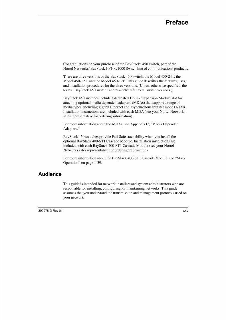
Preface
Congratulations on your purchase of the BayStack* 450 switch, part of the Nortel Networks* BayStack 10/100/1000 Switch line of communications products.
There are three versions of the BayStack 450 switch: the Model 450-24T, theModel 450-12T, and the Model 450-12F. This guide describes the features, uses,and installation procedures for the three versions. (Unless otherwise specified, theterms “BayStack 450 switch” and “switch” refer to all switch versions.)
BayStack 450 switches include a dedicated Uplink/Expansion Module slot forattaching optional media dependent adapters (MDAs) that support a range of media types, including gigabit Ethernet and asynchronous transfer mode (ATM).Installation instructions are included with each MDA (see your Nortel Networkssales representative for ordering information).
For more information about the MDAs, see Appendix C, “Media DependentAdapters.”
BayStack 450 switches provide Fail-Safe stackability when you install theoptional BayStack 400-ST1 Cascade Module. Installation instructions areincluded with each BayStack 400-ST1 Cascade Module (see your NortelNetworks sales representative for ordering information).
For more information about the BayStack 400-ST1 Cascade Module, see “StackOperation” on page 1-39.
Audience
This guide is intended for network installers and system administrators who areresponsible for installing, configuring, or maintaining networks. This guideassumes that you understand the transmission and management protocols used onyour network.
Using the BayStack 450 10/100/1000 Series Switch

7/23/2019 Baystack 450
http://slidepdf.com/reader/full/baystack-450 26/399
g y
xxvi 309978-D Rev 01
Organization
This guide has four chapters, eight appendixes, and an index:
If you want to: Go to:
Learn about your BayStack 450 switch and its key features Chapter 1
Install your BayStack 450 switch on a flat surface or in a 19-inchequipment rack, and verify its operation
Chapter 2
Connect to your BayStack 450 switch Console/Comm Port andlearn how to use the console interface (CI) menus to configure andmanage a standalone switch or a stack configuration
Chapter 3
Troubleshoot and diagnose problems with your BayStack 450switch
Chapter 4
View BayStack 450 switch operational and environmentalspecifications
Appendix A
View fiber optical characteristics of the (optional) gigabit1000BASE-SX/LX MDAs
Appendix B
Learn about optional MDAs you can use with your BayStack 450switch
Appendix C
Learn important ATM terminology and concepts that relate to theBayStack 450-2M3/2S3 MDAs
Appendix D
View Quick-Step flowcharts for using your BayStack 450 switchfeatures
Appendix E
Learn more about your BayStack 450 switch connectors (ports)and pin assignments
Appendix F
View a list of factory default settings for your BayStack 450switch
Appendix G
View a sample BootP configuration file Appendix H
View an alphabetical listing of the topics and subtopics in thisguide, with cross-references to relevant information
Index
Preface

7/23/2019 Baystack 450
http://slidepdf.com/reader/full/baystack-450 27/399
309978-D Rev 01 xxvii
Text Conventions
This guide uses the following text conventions:
bold text Indicates command names and options and text thatyou need to enter.
Example: Enter show ip {alerts | routes}.
Example: Use the dinfo command.
italic text Indicates file and directory names, new terms, booktitles, and variables in command syntax descriptions.Where a variable is two or more words, the words areconnected by an underscore.
Example: If the command syntax is:show at <valid_route >
valid_route is one variable and you substitute one value
for it.
screen text Indicates system output, for example, prompts andsystem messages.
Example: Set Trap Monitor Filters
[Enter] Named keys in text are enclosed in square brackets.
The notation [Enter] is used for the Enter key and theReturn key.
[Ctrl]-C Two or more keys that must be pressed simultaneouslyare shown in text linked with a hyphen (-) sign.
Using the BayStack 450 10/100/1000 Series Switch

7/23/2019 Baystack 450
http://slidepdf.com/reader/full/baystack-450 28/399
xxviii 309978-D Rev 01
Acronyms
This guide uses the following acronyms:
ATM asynchronous transfer mode
BootP Bootstrap Protocol
BPDU Bridge Protocol Data Unit
BUS broadcast and unknown server
CI console interfaceCRC cyclic redundancy check
CSMA/CD carrier sense multiple access/collision detection
CTS clear to send
DCE data communications equipment
DSR data set ready
DTE data terminal equipment
EAP Extensible Authentication Protocol
EAPOL Extensible Authentication Protocol Over LANs
ECM Entity Coordination Management
ELAN emulated LAN
FID filtering database identifier
HRPSU high-power redundant power supply unit
IGMP Internet Gateway Management Protocol
ILMI Interim local management interface
IP Internet Protocol
ISO International Organization for StandardizationISVN interoperability software version number
LANE LAN emulation
LEC LAN emulation client
LECS LAN emulation configuration server
(continued)
Preface

7/23/2019 Baystack 450
http://slidepdf.com/reader/full/baystack-450 29/399
309978-D Rev 01 xxix
LED light-emitting diode
LES LAN emulation server
MAC media access controlMDA media dependent adapter
MDI medium dependent interface
MDI-X medium dependent interface-crossover
MIB Management Information Base
MLT MultiLink TrunkNIC network interface controller
NMS network management station
PAE port access entity
PID Protocol Identifier
PVID port VLAN identifier
RADIUS Remote Authentication Dial-In User Services
RARP Reverse Address Resolution Protocol
RMON remote monitoring
RPSU redundant power supply unit
SNMP Simple Network Management Protocol
STA Spanning Tree Algorithm
STP Spanning Tree Protocol
TELNET Network Virtual Terminal Protocol
TFTP Trivial File Transfer Protocol
UNI user-to-network interface
UTP unshielded twisted pairVC virtual channel
VID VLAN identifier
VLAN virtual local area network
VP virtual path
Using the BayStack 450 10/100/1000 Series Switch
7/23/2019 Baystack 450
http://slidepdf.com/reader/full/baystack-450 30/399
xxx 309978-D Rev 01
Related Publications
For more information about using the BayStack 450 switch, refer to the following
publications:
• Installing Media Dependent Adapters (MDAs) (Part number 302403-F)
Describes how to install optional MDAs on your BayStack 450 switch.
• Gigabit Interface Converter (GBIC) Installation Guide (Part number208723-A)
Provides a list of GBICS that are available from Nortel Networks, andincludes procedures for installing/removing GBICs from supported devices,general specifications, cabling standards, and product descriptions for eachmodel.
• Installing the BayStack 400-ST1 Cascade Module (Part number 304433-B)
Describes how to install optional BayStack 400-ST1 Cascade Modules tocreate a stack configuration of up to eight supported switches.
• Installing and Maintaining the HRPSU (Part number 114312-D)
Describes how to install and maintain a Nortel Networks High PowerRedundant Power Supply Unit (HRPSU) to your switch.
• Wall Mounting Instructions (Part number 304602-A)
Describes how to mount up to two BayStack 350 or BayStack 450 switches on
any wall that can safely support the weight of the switches, including anyattached cables.
• Reference for the BayStack 350/410/450 Management Software Operations
(Part number 210245-C)
Describes the Nortel Networks Device Manager software, a set of graphicalnetwork management applications you can use to configure and manage the
BayStack 350/410/450 switches.• Bay Networks Guide to Implementing BaySecure LAN Access for Ethernet
(Part number 345-1106A)
Describes Nortel Networks real-time security system that safeguards Ethernetnetworks from unauthorized surveillance and intrusion.
Preface

7/23/2019 Baystack 450
http://slidepdf.com/reader/full/baystack-450 31/399
309978-D Rev 01 xxxi
• Managing Network Access with Optivity SecureLAN (Part number 312688-A)
Describes how you can use the Nortel Networks Optivity SecureLANapplication to control network access to your switch or stack.
You can print selected technical manuals and release notes free, directly from theInternet. Go to the www25.nortelnetworks.com/library/tpubs/ Web address. Findthe product for which you need documentation. Then locate the specific categoryand model or version for your hardware or software product. Use Adobe AcrobatReader to open the manuals and release notes, search for the sections you need,and print them on most standard printers. Go to the Adobe Systems Web address
at www.adobe.com to download a free copy of Acrobat Reader.
You can purchase selected documentation sets, CDs, and technical publicationsthough the Internet at the www1.fatbrain.com/documentation/nortel/ Web address.
How to Get Help
If you purchased a service contract for your Nortel Networks product from adistributor or authorized reseller, contact the technical support staff for that
distributor or reseller for assistance.
If you purchased a Nortel Networks service program, contact one of the following
Nortel Networks Technical Solutions Centers:
Technical Solutions Center Telephone
Billerica, MA 800-4NORTEL or (800) 466-7835
Santa Clara, CA 800-4NORTEL or (800) 466-7835
Valbonne, France (33) (4) 92-96-69-68
Sydney, Australia (61) (2) 9927-8800
Tokyo, J apan (8) (3) 5740-1700

7/23/2019 Baystack 450
http://slidepdf.com/reader/full/baystack-450 32/399

7/23/2019 Baystack 450
http://slidepdf.com/reader/full/baystack-450 33/399
309978-D Rev 01 1-1
Chapter 1
BayStack 450 10/100/1000 Series Switches
This chapter introduces the BayStack 450 switch and covers the following topics:
• “Physical Description” (page 1-2)
• “Features” (page 1-13)
• “SNMP Support” (page 1-16)
• “Security” (page 1-17)
• “Flash Memory Storage” (page 1-29)
• “Configuration and Switch Management” (page 1-30)
• “BootP Automatic IP Configuration/MAC Address” (page 1-31)
• “Autosensing and Autonegotiation” (page 1-31)
• “Network Configurations” (page 1-32)
• “Stack Operation” (page 1-39)• “Virtual Local Area Networks (VLANs)” (page 1-49)
• “IGMP Snooping” (page 1-69)
• “IEEE 802.1p Prioritizing” (page 1-74)
• “MultiLink Trunks” (page 1-78)
• “Port Mirroring (Conversation Steering)” (page 1-97)
Using the BayStack 450 10/100/1000 Series Switch

7/23/2019 Baystack 450
http://slidepdf.com/reader/full/baystack-450 34/399
1-2 309978-D Rev 01
Physical Description
There are three versions of the BayStack 450 switch: the BayStack 450-24T
switch, the BayStack 450-12T switch, and the BayStack 450-12F switch (Figure 1-1).
Figure 1-1. BayStack 450 Switch Versions
Front Panel
Figure 1-2 shows the front-panel configurations for the three BayStack 450 switchmodels. Descriptions of the front-panel components follow the figures.
For a description of the components located on the back panel of the BayStack450 switch, see “Back Panel” on page 1-10.
BayStack 450-24T
BayStack 450-12T
BS45001B
BayStack 450-12F
BayStack 450 10/100/1000 Series Switches

7/23/2019 Baystack 450
http://slidepdf.com/reader/full/baystack-450 35/399
309978-D Rev 01 1-3
Figure 1-2. BayStack 450 Switch Front Panels
1
2
3
4
= Comm Port
= Uplink/Expansion Module slot
= Port connectors
= LED display panel BS45078A
Uplink/Expansion Module 282 6 2 725
Comm Port
17 1913 15 21
18 2014 16 22 24
23
Status Dwn
P wr U p
Cas
RPSUBaseActivity
Activity
10/100
10/100
1 2 3 4
BayStack 450-24T
5 71 3 9
6 82 4 10 12
11
Uplink/Expansion Module 16
Comm Port
13 1514
RPSU
Dwn
Pwr
Cas
Up
Status
BaseActivity
Activity
10/100
10/100
1 2 3 4
BayStack 450-12T
5 71 3 9
6 82 4 10 12
11
Uplink/Expansion Module 161 4 1 513
Comm Port
Status Dwn
P wr U p
Cas
RPSUBaseActivity
Link
F Dx
1 2 3 4
BayStack 450-12F
5 71 3 96 82 4 10 1211
Using the BayStack 450 10/100/1000 Series Switch
7/23/2019 Baystack 450
http://slidepdf.com/reader/full/baystack-450 36/399
1-4 309978-D Rev 01
Comm Port
The Comm Port (also referred to as the Console/Comm Port) allows you to access
the console interface (CI) screens and customize your network using the suppliedmenus and screens (see Chapter 3, “Using the Console Interface”).
The Console/Comm Port is a DB-9, RS-232-D male serial port connector. You canuse this connector to connect a management station or console/terminal to theswitch by using a straight-through DB-9 to DB-9 standard serial port cable (see“Console/Comm Port” on page 2-10).
The console port default settings are: 9600 baud with 8 data bits, 1 stop bit, and noparity as the communications format, with Flow control set to Xon/Xoff.
Uplink/Expansion Module Slot
The Uplink/Expansion Module slot allows you to attach optional media dependentadapters (MDAs) that support a range of media types (see Appendix C, “MediaDependent Adapters” for more information about MDA types available fromNortel Networks).
10BASE-T/100BASE-TX Ports
Your BayStack 450-24T and BayStack 450-12T switches use 10BASE-T/100BASE-TX RJ-45 (8-pin modular) port connectors.
Note: The Console/Comm Port is configured as a data communicationsequipment (DCE) connector. Ensure that your RS-232 cable pinouts areconfigured for DCE connections (see “DB-9 (RS-232-D) Console/Comm PortConnector” on page F-5).
Note: The RJ-45 port connectors on BayStack 450 switches manufactured
prior to December 1998 are numbered 1 to 12 and 13 to 24, in succession fromleft to right. Later units use port connectors that are configured with one or twodual, six-port groups, numbered 1 to 12 and 13 to 24. The top rows are oddnumbered and the bottom rows are even numbered (see Figure 1-2 onpage 1-3). Port-specific examples in this guide show the appropriate portconnections when required; other examples apply to both versions.
BayStack 450 10/100/1000 Series Switches
7/23/2019 Baystack 450
http://slidepdf.com/reader/full/baystack-450 37/399
309978-D Rev 01 1-5
The 10BASE-T/100BASE-TX port connectors are configured as MDI-X(media-dependent interface-crossover). These ports connect over straight cables tothe network interface controller (NIC) card in a node or server, similar to a
conventional Ethernet repeater hub. If you are connecting to an Ethernet hub orEthernet switch, you need a crossover cable unless an MDI connection exists onthe associated port of the attached device (see “MDI and MDI-X Devices” onpage F-2).
Your BayStack 450-24T and BayStack 450-12T switches use autosensing portsthat are designed to operate at 10 Mb/s or at 100 Mb/s, depending on theconnecting device. These ports support the IEEE 802.3u autonegotiation standard,which means that when a port is connected to another device that also supports theIEEE 802.3u standard, the two devices negotiate the best speed and duplex mode.
The 10BASE-T/100BASE-TX RJ-45 switch ports also support half- andfull-duplex mode operation, and can connect to 10 Mb/s or 100 Mb/s Ethernetsegments or nodes (see “Connecting the 10BASE-T/100BASE-TX Ports” onpage 2-8).
See Appendix F, “Connectors and Pin Assignments,” for more information aboutthe RJ-45 port connectors.
100BASE-FX MT-RJ Ports
Your BayStack 450-12F switch uses longwave 1300 nanometer (nm) MT-RJ portconnectors to attach devices over 62.5/125 or 50/125 micron multimode fiberoptic cable.
BayStack 450-12F switches conform to the IEEE 802.3u 100BASE-FX standard
and can be used for fiber-based 100 Mb/s connections (2 km/1.2 mi maximumdistance) to other compatible Fast Ethernet devices. Single-mode fiber cable is notsupported.
Note: Use only Category 5 copper unshielded twisted pair (UTP) cableconnections when connecting 10BASE-T/100BASE-TX ports.
Using the BayStack 450 10/100/1000 Series Switch
LED Di l P l

7/23/2019 Baystack 450
http://slidepdf.com/reader/full/baystack-450 38/399
1-6 309978-D Rev 01
LED Display Panel
Figures 1-3 and 1-4 show the BayStack 450-24T, BayStack 450-12T, and the
BayStack 450-12F LED display panels.See Table 1-1 for a description of the LEDs.
Figure 1-3. BayStack 450-24T/12T LED Display Panel
450-12T Switch
450-24T SwitchBayStack
Status Dwn
Pwr Up
1 53Cas
RPSUBase
BayStack
Activity
Activity
2119 2310/100
10/100
Activity
Activity
10/100
10/100
1713 15117 9
2 64 2220 241814 16128 10
BayStack 450-24T
BayStack 450-12T
BS45079A
1 53 117 9
2 64 128 10
Status Dwn
Pwr Up
Cas
RPSUBase
BayStack 450 10/100/1000 Series Switches

7/23/2019 Baystack 450
http://slidepdf.com/reader/full/baystack-450 39/399
309978-D Rev 01 1-7
Figure 1-4. BayStack 450-12F LED Display Panel
Table 1-1. BayStack 450 Switch LED Descriptions
Label Type Color State Meaning
Pwr Power status Green On DC power is available to the switch’s internal circuitry.
Off No AC power to switch, or power supply failed.
Status System status Green On Self-test passed successfully and switch is operational.
Blinking A nonfatal error occurred during the self-test.
Off The switch failed the self-test.
RPSU RPSU status Green On The switch is connected to the HRPSU and can receive
power if needed.
Off The switch is not connected to the HRPSU or HRPSU is
not supplying power.
Cas Up Stack mode Off The switch is in standalone mode.
Green On The switch is connected to the upstream unit’s Cascade AIn connector.
Yellow On The Cascade A Out connector (Cas Up) for this switch is
looped internally (wrapped to the secondary ring).
(continued)
BayStack 450-12F
BS45080A
450-12F SwitchBayStack
Status Dwn
Pwr Up 1 53
Cas
RPSUBaseActivity
Link
F Dx
117 92 64 128 10
Using the BayStack 450 10/100/1000 Series Switch
Table 1-1 BayStack 450 Switch LED Descriptions (continued)

7/23/2019 Baystack 450
http://slidepdf.com/reader/full/baystack-450 40/399
1-8 309978-D Rev 01
Yellowor Green
Blinking Incompatible software revision or unable to obtain a unitID (Renumber Stack Unit table full). The unit is on the ring
but cannot participate in the stack configuration.
Cas Dwn Stack mode Off The switch is in standalone mode.
Green On The switch is connected to the downstream unit’s
Cascade A Out connector.
Yellow On The Cascade A In connector (Cas Dwn) for this switch is
looped internally (wrapped to the secondary ring).Yellow
or Green
Blinking Incompatible software revision or unable to obtain a unit
ID (Renumber Stack Unit table full). The unit is on the ring
but cannot participate in the stack configuration.
Base Base mode Green On The switch is configured as the stack base unit.
Off The switch is not configured as the stack base unit (or is
in standalone mode).
Blinking Stack configuration error: Indicates that multiple baseunits or no base units are configured in the stack.
Yellow On This unit is operating as the stack configuration’s
temporary base unit . This condition occurs automatically
if the base unit (directly downstream from this unit) fails.
If this happens, the following events take place:
• The two units directly upstream and directly
downstream from the failed unit automatically wraptheir cascade connectors and indicate this condition
by lighting their Cas Up and Cas Dwn LEDs (see Cas
Up and Cas Dwn description in this table).
• If the temporary base unit fails, the next unit directly
downstream from this unit becomes the new
temporary base unit. This process can continue until
there are only two units left in the stack configuration.
This automatic failover is a temporary safeguard only. If
the stack configuration loses power, the temporary base
unit will not power up as the base unit when power is
restored. For this reason, you should always assign the
temporary base unit as the base unit (set the Unit Select
switch to Base) until the failed unit is repaired or replaced.
(continued)
Table 1-1. BayStack 450 Switch LED Descriptions (continued)
Label Type Color State Meaning
BayStack 450 10/100/1000 Series Switches
Table 1-1. BayStack 450 Switch LED Descriptions (continued)

7/23/2019 Baystack 450
http://slidepdf.com/reader/full/baystack-450 41/399
309978-D Rev 01 1-9
10/100 10/100 Mb/sport speed
indicator
Green On The corresponding port is set to operate at 100 Mb/s andthe link is good.
Green Blinking The corresponding port has been disabled by software.
Yellow On The corresponding port is set to operate at 10 Mb/s and
the link is good.
Yellow Blinking The corresponding port has been disabled by software.
Off The link connection is bad or there is no connection tothis port.
Link Link status Green On BayStack 450-12F model only: Valid communications link
established.
Off The communications link connection is bad or there is no
connection to this port.
Blinking The corresponding port is management disabled.
F Dx Duplex status Green On BayStack 450-12F model only: The corresponding port isin full-duplex mode.
Off The corresponding port is in half-duplex mode.
Activity Port activity Green Blinking Indicates network activity for the corresponding port. A
high level of network activity can cause the LEDs to
appear to be on continuously.
Table 1 1. BayStack 450 Switch LED Descriptions (continued)
Label Type Color State Meaning
Using the BayStack 450 10/100/1000 Series Switch
Back Panel
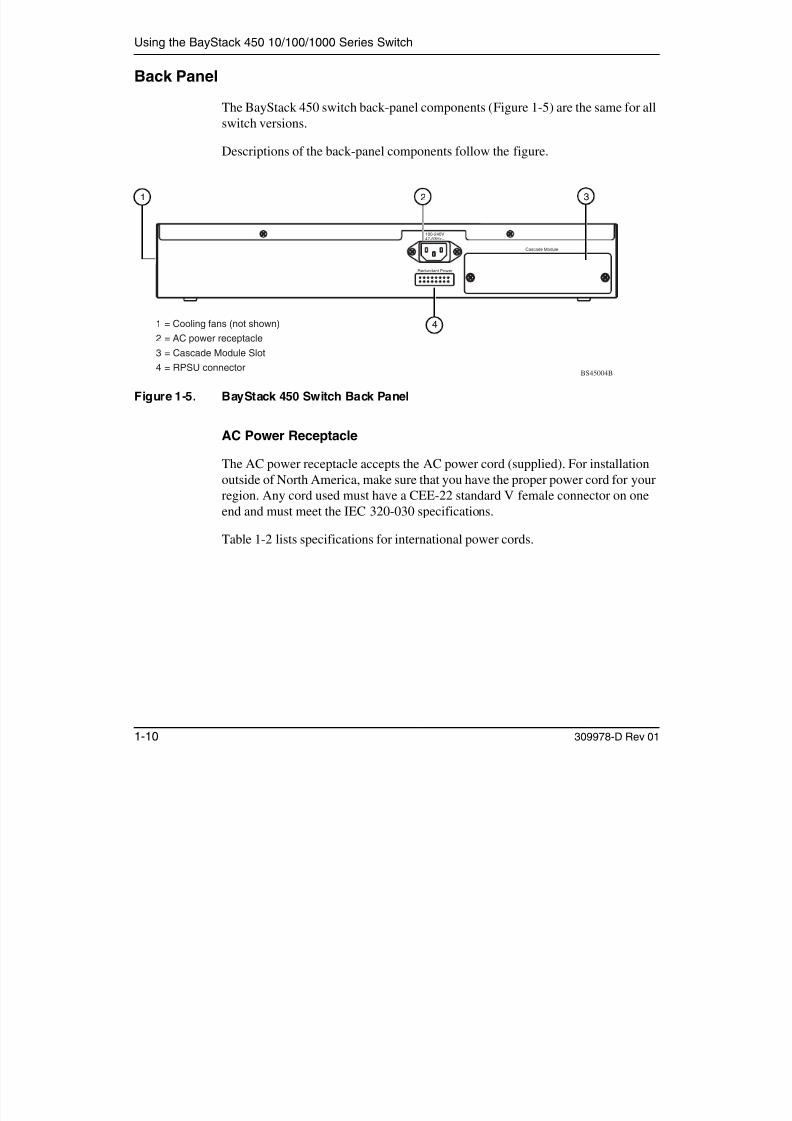
7/23/2019 Baystack 450
http://slidepdf.com/reader/full/baystack-450 42/399
1-10 309978-D Rev 01
Back Panel
The BayStack 450 switch back-panel components (Figure 1-5) are the same for all
switch versions.Descriptions of the back-panel components follow the figure.
Figure 1-5. BayStack 450 Switch Back Panel
AC Power Receptacle
The AC power receptacle accepts the AC power cord (supplied). For installationoutside of North America, make sure that you have the proper power cord for yourregion. Any cord used must have a CEE-22 standard V female connector on oneend and must meet the IEC 320-030 specifications.
Table 1-2 lists specifications for international power cords.
Cascade Module
Redundant Power
100-240V47-63Hz~
2 3
1
2
34
= Cooling fans (not shown)
= AC power receptacle
= Cascade Module Slot= RPSU connector
BS45004B
1
4
BayStack 450 10/100/1000 Series Switches

7/23/2019 Baystack 450
http://slidepdf.com/reader/full/baystack-450 43/399
309978-D Rev 01 1-11
Table 1-2. International Power Cord Specifications
Country/Plug description Specifications Typical plug
Continental Europe:
• CEE7 standard VII male plug
• Harmonized cord (HAR marking
on the outside of the cord jacket
to comply with the CENELEC
Harmonized Document HD-21)
220 or 230 VAC
50 Hz
Single phase
U.S./Canada/Japan:
• NEMA5-15P male plug
• UL recognized (UL stamped
on cord jacket)
• CSA certified (CSA label
secured to the cord)
100 or 120 VAC
50–60 Hz
Single phase
United Kingdom:
• BS1363 male plug with fuse• Harmonized cord
240 VAC
50 HzSingle phase
Australia:
• AS3112-1981 Male plug
240 VAC
50 Hz
Single phase
228FA
227FA
229FA
230FA
Using the BayStack 450 10/100/1000 Series Switch
Redundant Power Supply Unit (RPSU) Connector

7/23/2019 Baystack 450
http://slidepdf.com/reader/full/baystack-450 44/399
1-12 309978-D Rev 01
The RPSU connector allows you to connect a backup power supply unit to theswitch. Nortel Networks provides an (optional) high-power redundant powersupply unit (HRPSU) for this purpose. The HRPSU is a hot-swappable powersupply unit that provides uninterrupted operation to up to four BayStack 450switches in the event that any of the switch power supplies fail.
Nortel Networks provides the HRPSU power rack (Order No. AA0002001) withfour slots for power supply modules (Order No. AA0005003). Each HRPSU cansupport up to four BayStack 450 switches. Installation instructions are provided
with the HRPSU (refer to Installing and Maintaining the HRPSU (Part number114312-D).
Contact your Nortel Networks sales representative for more information about theHRPSU.
Cascade Module Slot
The Cascade Module slot allows you to attach an optional BayStack 400-ST1Cascade Module to the switch (see “Stack Operation” on page 1-39).
You can connect up to eight BayStack 450 switches to form a redundant stackconfiguration. BayStack 450 switches use a fail-safe cascade stacking architecturewhich, in the unlikely event of a switch failure, maintains the integrity of theremaining stack: all signals are looped back at the point of failure. Because each
unit in the stack has a full copy of the stack configuration, operation of the stackcontinues without affecting application connectivity.
Any mix of up to eight BayStack 450 switches, BayStack 410-24T switches, andthe Business Policy Switch 2000 can be stacked to provide a total of 224 portswhen all MDA slots are configured with the maximum port availability (certainrestrictions apply, see “Stack Operation on page 1-39).
Installation instructions are provided with each BayStack 400-ST1 CascadeModule (see Installing the BayStack 400-ST1 Cascade Module).
See your Nortel Networks sales representative for ordering information.
BayStack 450 10/100/1000 Series Switches
Cooling Fans

7/23/2019 Baystack 450
http://slidepdf.com/reader/full/baystack-450 45/399
309978-D Rev 01 1-13
The variable-speed cooling fans (not shown) are located on one side of the
BayStack 450 switch to provide cooling for the internal components. When youinstall the switch, be sure to allow enough space on both sides of the switch foradequate air flow.
Features
BayStack 450 switches provide wire-speed switching that allows
high-performance, low-cost connections to full-duplex and half-duplex 10/100/1000 Mb/s Ethernet local area networks (LANs).
BayStack 450 switches offer the following features:
• High-speed forwarding rate: Up to 3 million packets per second (peak)
• Store-and-forward switch: Full-performance forwarding at full line speed,using a 2.56 Gigabit/second switch fabric
• Learning rate: 3 million addresses per second (peak)
• Address database size: 16,000 entries at line rate (32,000 entries withoutflooding)
• Fail-safe stacking: Provides uninterrupted connectivity for up to eight units,with up to 224 ports stacked together as one managed unit (requires one
optional BayStack 400-ST1 Cascade Module kit per stacked unit. See yourNortel Networks sales representative for ordering information).
• Spanning Tree Protocol (STP): Complies with IEEE 802.1D standard. STPcan be disabled on the entire switch or stack, or on a per-port basis.
• SNMP agent support
• High-speed Uplink/Expansion Module slot: Allows you to attach optional
media dependent adapters (MDAs) that support a range of media types.• Rate limiting: Adjustable broadcast or IP multicast packet-rate limits for
control of broadcast and IP multicast storms.
• Console/Comm port: Allows you to configure and manage the switch locallyor remotely.
• IGMP snooping
• IEEE 802.1p prioritizing
Using the BayStack 450 10/100/1000 Series Switch
• Virtual local area networks (VLANs), supporting:

7/23/2019 Baystack 450
http://slidepdf.com/reader/full/baystack-450 46/399
1-14 309978-D Rev 01
-- IEEE 802.1Q port-based VLANs
-- Protocol-based VLANs• TELNET:
-- Support for up to four simultaneous TELNET sessions
-- Optional password protection
-- Login time-out
-- Failed-login guard-- Inactivity time-out
-- Allowed source addresses
-- Event logging
• IEEE 802.3u-compliant autonegotiation ports, with four modes:
-- 10BASE-T half-duplex-- 10BASE-T full-duplex
-- 100BASE-TX half-duplex
-- 100BASE-TX full-duplex
• MultiLink Trunking, supporting:
-- Switch-to-switch trunks-- Switch-to-server trunks
• Port mirroring (conversation steering)
-- Port-based
-- MAC address-based
• Remote monitoring (RMON), with four groups integrated:-- Statistics
-- History
-- Alarms
-- Events
BayStack 450 10/100/1000 Series Switches
• Security:
7/23/2019 Baystack 450
http://slidepdf.com/reader/full/baystack-450 47/399
309978-D Rev 01 1-15
-- MAC address-based security: Allows you to limit access to the switchbased on MAC addresses.
-- EAPOL-based security: EAP over LANs (EAPOL) security allows you tolimit access to the switch based on the Extensible Authentication Protocol(EAP).
-- RADIUS-based security: Allows you to set up your switch with RemoteAuthentication Dial-In User Services (RADIUS) security, forauthenticating TELNET logins.
-- SNMP-based security: Allows you to limit administration access to theswitch via IP filtering.
• Front-panel light-emitting diodes (LEDs) to monitor the following:
-- Power status
-- System status
-- Stack status for the following:-- Cascade Up and Cascade Down status
-- Base unit status
-- RPSU status
-- Per-port status for the following:
-- 1000 Mb/s link-- 100 Mb/s link
-- 10 Mb/s link
-- Half- and full-duplex transmission
-- Tx/Rx activity
-- Management enable/disable• Configuration file download/upload support: Allows you to store your switch/
stack configuration parameters on a TFTP server.
• Upgradable device firmware in nonvolatile flash memory using the TrivialFile Transfer Protocol (TFTP).
Using the BayStack 450 10/100/1000 Series Switch
SNMP Support

7/23/2019 Baystack 450
http://slidepdf.com/reader/full/baystack-450 48/399
1-16 309978-D Rev 01
The following two sections describe the SNMP support for the BayStack 450
switch.
MIBs
The BayStack 450 switch supports an SNMP agent with industry-standard MIBs,as well as private MIB extensions, which ensures compatibility with existingnetwork management tools. The BayStack 450 switch supports the MIB-II (RFC 1213), the Bridge MIB (RFC 1493), and the RMON MIB (RFC 1757),which provide access to detailed management statistics.
The following MIBs are supported:
• EAPOL (IEEE 802.1X Port Access Control MIB)
• SNMPv2 (RFC 1907)
• Bridge MIB (RFC 1493)• Ethernet MIB (RFC 1643)
• RMON MIB (RFC 1757)
• MIB-II (RFC 1213)
• Interface MIB (RFC 1573)
• ATM Forum LAN Emulation Client MIB• Nortel Networks proprietary MIBs:
-- s5Chas MIB
-- s5Agent MIB
-- s5 Ethernet Multi-segment Topology MIB
-- s5 Switch BaySecure MIB-- Rapid City MIB
BayStack 450 10/100/1000 Series Switches
SNMP Traps
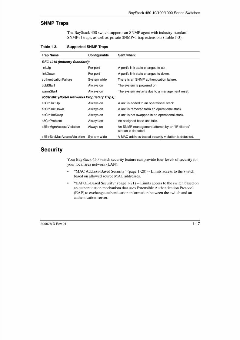
7/23/2019 Baystack 450
http://slidepdf.com/reader/full/baystack-450 49/399
309978-D Rev 01 1-17
The BayStack 450 switch supports an SNMP agent with industry-standard
SNMPv1 traps, as well as private SNMPv1 trap extensions (Table 1-3).
Security
Your BayStack 450 switch security feature can provide four levels of security foryour local area network (LAN):
• “MAC Address-Based Security” (page 1-20) -- Limits access to the switchbased on allowed source MAC addresses.
• “EAPOL-Based Security” (page 1-21) -- Limits access to the switch based onan authentication mechanism that uses Extensible Authentication Protocol(EAP) to exchange authentication information between the switch and anauthentication server.
Table 1-3. Supported SNMP Traps
Trap Name Configurable Sent when:
RFC 1215 (Industry Standard):
linkUp Per port A port’s link state changes to up.
linkDown Per port A port’s link state changes to down.
authenticationFailure System wide There is an SNMP authentication failure.
coldStart Always on The system is powered on.
warmStart Always on The system restarts due to a management reset.
s5Ctr MIB (Nortel Networks Proprietary Traps):
s5CtrUnitUp Always on A unit is added to an operational stack.
s5CtrUnitDown Always on A unit is removed from an operational stack.
s5CtrHotSwap Always on A unit is hot-swapped in an operational stack.
s5CtrProblem Always on An assigned base unit fails.
s5EtrMgmAccessViolation Always on An SNMP management attempt by an “IP filtered”
station is detected.
s5EtrSbsMacAccessViolation System wide A MAC address-based security violation is detected.
Using the BayStack 450 10/100/1000 Series Switch
• “RADIUS-Based Security” (page 1-28) -- Limits administrative access to theswitch through user authentication.

7/23/2019 Baystack 450
http://slidepdf.com/reader/full/baystack-450 50/399
1-18 309978-D Rev 01
switch through user authentication.
• “SNMP-Based Security” (page 1-29) -- Limits administration access via
selective IP filtering.
Figure 1-6 shows an example of a typical campus configuration using theBayStack 450 switch security features.
Figure 1-6. BayStack 450 Switch Security Feature Example
In this configuration example, the following security measures are implemented:
• The switch
The switch is located in a locked closet, accessible only by authorized
Technical Services personnel.
Library
Teachers’ officesand classrooms
To NetworkCenter
= Secure locked area
Legend
Student Dormitory
Switch
RADIUS server
RADIUS-basedsecurity
BS45077A
BayStack 450 10/100/1000 Series Switches
-- MAC address-based security allows up to 448 authorized stations (MACaddresses) access to one or more switch ports (see “MAC Address-Based

7/23/2019 Baystack 450
http://slidepdf.com/reader/full/baystack-450 51/399
309978-D Rev 01 1-19
) p (Security” on page 1-20).
-- EAPOL-based security provides port-based network access control toauthenticate devices based on user authentication (see “EAPOL-BasedSecurity” on page 1-21).
-- RADIUS-based security limits administrative access through userauthentication (see “RADIUS-Based Security” on page 1-28).
-- SNMP-based security limits administrative access through selective IP
filtering (see “SNMP-Based Security” on page 1-29).• Student dormitory
Dormitory rooms, typically occupied by two students, are prewired with twoRJ-45 jacks. Only students who are authorized (as specified by the MACaddress-based security feature) can access the switch on the secured ports.
• Teachers’ offices and classrooms
The PCs that are located in the teachers’ offices and in the classrooms areassigned MAC address-based security that is specific for each classroom andoffice location. The security feature logically locks each wall jack to thespecified station and prevents unauthorized access to the switch shouldsomeone attempt to connect a personal laptop PC into the wall jack.
The printer is assigned as a single station and is allowed full bandwidth onthat switch port. It is assumed that all PCs are password protected and that theclassrooms and offices are physically secured.
• Library
The wall jacks in the library are set up so that the PCs can be connected to anywall jack in the room. This allows the PCs to be moved anywhere in the room.The exception is the printer, which is assigned as a single station with fullbandwidth to that port. It is assumed that all PCs are password protected and
that access to the library is physically secured.
Using the BayStack 450 10/100/1000 Series Switch
MAC Address-Based Security

7/23/2019 Baystack 450
http://slidepdf.com/reader/full/baystack-450 52/399
1-20 309978-D Rev 01
The MAC address-based security feature allows you to set up network access
control, based on source MAC addresses of authorized stations.You can:
• Create a list of up to 448 MAC addresses and specify which addresses areauthorized to connect to your switch or stack configuration. The 448 MACaddresses can be configured within a single standalone switch or they can bedistributed in any order among the units in a single stack configuration.
• Specify which of your switch ports each MAC address is allowed to access.The options for allowed port access include: NONE, ALL, and single ormultiple ports that are specified in a list, for example, 1/1-4,1/6,2/9 (see “PortList Syntax” on page 3-35).
• Specify optional actions your switch can take if the software detects a securityviolation.
The switch can send a trap, turn on destination address (DA) filtering, disablethe specific port, or use any combination of these three options.
For instructions on using the console interface (CI) to set up MAC address-basednetwork access control, see “MAC Address-Based Security” on page 3-24.
See also Appendix E, “Quick Steps to Features,” for configuration flowcharts thatcan help you use this feature.
The MAC address-based security feature is based on Nortel NetworksBaySecure™ LAN Access for Ethernet, a real-time security system that safeguards
Ethernet networks from unauthorized surveillance and intrusion.
To learn more about Nortel Networks BaySecure LAN Access for Ethernet, referto the Bay Networks Guide to Implementing BaySecure LAN Access for Ethernet (Part number 345-1106A).
Note: You cannot configure a port for MAC Address-based security if the portis currently configured for EAPOL-based security.
BayStack 450 10/100/1000 Series Switches
EAPOL-Based Security

7/23/2019 Baystack 450
http://slidepdf.com/reader/full/baystack-450 53/399
309978-D Rev 01 1-21
The EAPOL-based security feature uses the Extensible Authentication Protocol
(EAP), as described in the IEEE Draft P802.1X, to allow you to set up networkaccess control on internal LANs. EAP allows the exchange of authenticationinformation between any end station or server connected to the switch and anauthentication server (such as a RADIUS server). This feature operates inconjunction with a RADIUS-based server to extend the benefits of remoteauthentication to internal LAN clients (see “RADIUS-Based Security” onpage 1-28).
This section covers the following topics:• “Security Example” (page 1-21)
• “Overview and Terms” (page 1-23)
• “Dynamic VLAN Assignment” (page 1-24)
• “Setting Up the Authentication Server” (page 1-25)
• “Authentication Process” (page 1-26)• “System Requirements” (page 1-27)
• “Configuration Rules” (page 1-28)
For instructions on using the console interface (CI) to set up EAPOL-basedsecurity, see “EAPOL Security Configuration” on page 3-40.
See also Appendix E, “Quick Steps to Features,” for configuration flowcharts thatcan help you use this feature.
Security Example
The following example illustrates how the BayStack 450 switch, configured withthe EAPOL-based security feature, reacts to a new network connection:
1. The switch detects a new connection on one of its ports (Figure 1-7).
a. The switch requests a user ID from the new client (1).
b. EAPOL encapsulates and forwards the user ID to the RADIUS server (2).
c. The RADIUS server requests the user’s password (3).
2. The new client forwards an encrypted password to the switch, within the
EAPOL packet (Figure 1-8).
Using the BayStack 450 10/100/1000 Series Switch
a. The switch relays the EAPOL packet to the RADIUS server (4).
b. If the RADIUS server validates the password (5), the new client is

7/23/2019 Baystack 450
http://slidepdf.com/reader/full/baystack-450 54/399
1-22 309978-D Rev 01
p w ( ), wallowed access to the switch and the network (6).
Figure 1-7. EAPOL-Based Security (1 of 2)
Figure 1-8. EAPOL-Based Security (2 of 2)
BS45097A
RADIUS server
New client PC
Switch requestsuser ID
1
2 Switch forwardsuser ID to
RADIUS Server
Password?
3 Password request
RADIUS server
New client PC
BS45098A
Encrypted password
4 Switch forwardspassword
********
RADIUS server
New client PC
5
RADIUS server
6
Password
validated
Access tonetworkapproved
Clientaccesses
network
New client PC
********
BayStack 450 10/100/1000 Series Switches
Overview and Terms
This section provides a detailed description of EAPOL-based security including
7/23/2019 Baystack 450
http://slidepdf.com/reader/full/baystack-450 55/399
309978-D Rev 01 1-23
This section provides a detailed description of EAPOL based security, includingan overview of the components and terms used with this feature.
Some components of EAPOL-based security are:
• Supplicant -- the entity that the Authenticator is authorizing. The supplicantcan be any end station or server that is connected to the switch. In thepreceding example, the supplicant is the new client PC.
• Authenticator -- a software entity whose sole purpose is to authorize a
supplicant that is attached to the other end of a LAN segment.• Authentication Server -- a RADIUS server that provides authorization
services to the Authenticator.
• Port Access Entity (PAE) -- a software entity associated with each port thatsupports the Authenticator or Supplicant functionality. In the precedingexample, the Authenticator PAE resides on the switch.
• Controlled Port -- any switch port whose operational state is influenced by theAuthenticator. In the preceding example, the controlled port is the switch portthat is connected to the new client PC.
The Authenticator communicates with the Supplicant using an encapsulationmechanism known as EAP over LANs (EAPOL).
The Authenticator PAE encapsulates the EAP message into a RADIUS packet
before sending the packet to the Authentication Server. The Authenticator doesnot interfere with authentication exchanges that occur between the Supplicant andthe Authentication Server (except for encapsulating the EAP message to make itsuitable for the packet’s destination).
The Authenticator determines the controlled port’s operational state. After theRADIUS server notifies the Authenticator PAE about the success or failure of theauthentication, it changes the controlled port’s operational state accordingly.
The Authenticator PAE functionality is implemented for each controlled port onthe switch. At system initialization, or when a supplicant is initially connected tothe switch’s controlled port, the controlled port’s state is set to Blocking. Duringthat time, only EAP packets can be received from the supplicant.
Using the BayStack 450 10/100/1000 Series Switch
When the Authentication server returns a “success” or “failure” message, thecontrolled port’s state is changed accordingly. If the authorization is successful,the controlled port’s operational state is set to Forwarding Otherwise the
7/23/2019 Baystack 450
http://slidepdf.com/reader/full/baystack-450 56/399
1-24 309978-D Rev 01
the controlled port s operational state is set to Forwarding. Otherwise, thecontrolled port’s state depends on the Operational Traffic Control field value inthe EAPOL Security Configuration screen (see Figure 3-16 on page 3-41).
The Operational Traffic Control field can have one of the following two values:
• Incoming and Outgoing -- If the controlled port is unauthorized, frames arenot transmitted through the port; all frames received on the controlled port arediscarded. The controlled port’s state is set to Blocking.
• Incoming -- If the controlled port is unauthorized, frames received on the portare discarded, but the transmit frames are forwarded through the port.
Dynamic VLAN Assignment
If EAPOL-based security is enabled on a port, and then the port is authorized, theEAPOL feature dynamically changes the port’s VLAN configuration according topreconfigured values, and assigns a new VLAN. The new VLAN configurationvalues are applied according to previously stored parameters (based on theuser_ID) in the Authentication server (see “Setting Up the Authentication Server”following this section).
The following VLAN configuration values are affected:
• Port Membership
• PVID• Port Priority
When the EAPOL-based security is disabled on a port that was previouslyauthorized, the port’s VLAN configuration values are restored directly from theswitch’s nonvolatile random access memory (NVRAM).
The following exceptions apply to dynamic VLAN assignments:
• The dynamic VLAN configuration values assigned by EAPOL are not storedin the switch’s NVRAM.
• You can overide the dynamic VLAN configuration values assigned byEAPOL; however, the values you configure are not stored in NVRAM.
BayStack 450 10/100/1000 Series Switches
• When EAPOL is enabled on a port, and you configure values other thanVLAN configuration values, those values are applied and stored in NVRAM.

7/23/2019 Baystack 450
http://slidepdf.com/reader/full/baystack-450 57/399
309978-D Rev 01 1-25
For more information about VLANs, see “Virtual Local Area Networks
(VLANs)” on page 1-49.
Setting Up the Authentication Server
This section describes how to set up your Authentication server (RADIUS server)for EAPOL dynamic VLAN assignments. The Authentication server allows youto configure user-specific settings for VLAN memberships and port priority.
When you log on to a system that has been configured for EAPOL authentication,the Authentication server recognizes your user ID and notifies the switch to assignpreconfigured (user-specific) VLAN membership and port priorities to the switch.The configuration settings are based on configuration parameters that werecustomized for your user ID and previously stored on the Authentication server.
To set up the Authentication server, set the following “Return List” attributes for
all user configurations (refer to your Authentication server documentation):• VLAN Membership Attributes
-- Tunnel-Type: value 13, Tunnel-Type-VLAN
-- Tunnel-Medium-Type: value 6, Tunnel-Medium-Type-802
-- Tunnel-Private-Group-Id: ASCII value 1 to 4094 (this value is used to
identify the specified VLAN)• Port Priority (Vendor-Specific) Attributes
-- Vendor Id: value 562, Nortel Networks vendor ID
-- Attribute Number: value 1, Port Priority
-- Attribute Value: value 0 (zero) to 7 (this value is used to indicate the portpriority value assigned to the specified user)
Using the BayStack 450 10/100/1000 Series Switch
Authentication Process
The flowcharts shown in Figures 1-9 and 1-10 describe the authentication process.

7/23/2019 Baystack 450
http://slidepdf.com/reader/full/baystack-450 58/399
1-26 309978-D Rev 01
Figure 1-9. Authentication Process Flowchart (1 of 2)
Yes
No
BS45099A
Authenticationsuccessful?
Authenticationserver sentVLAN ID?
Yes
Yes
No
DoesVLANexist?
No
Login screen
Access denied.See System Administrator.
Off-page reference
On-page reference
Key
Switch restores VLAN ID and PVIDvalues from NVRAM.
Switch sets VLAN ID and PVIDvalues to VLAN 1.
Yes
Port-basedVLAN?
No
Switch sets VLAN ID and PVID valuesto preconfigured values stored in
the Authentication server.
A
A
A
BayStack 450 10/100/1000 Series Switches
A
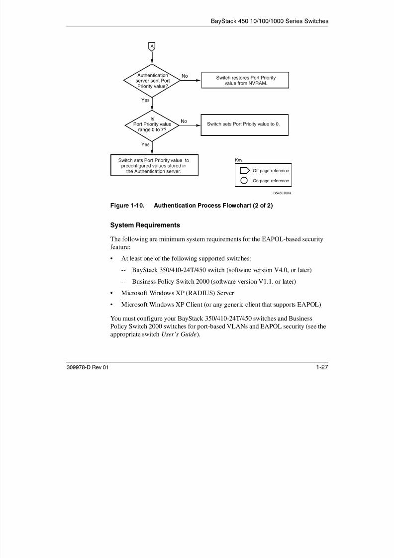
7/23/2019 Baystack 450
http://slidepdf.com/reader/full/baystack-450 59/399
309978-D Rev 01 1-27
Figure 1-10. Authentication Process Flowchart (2 of 2)
System Requirements
The following are minimum system requirements for the EAPOL-based securityfeature:
• At least one of the following supported switches:
-- BayStack 350/410-24T/450 switch (software version V4.0, or later)
-- Business Policy Switch 2000 (software version V1.1, or later)
• Microsoft Windows XP (RADIUS) Server• Microsoft Windows XP Client (or any generic client that supports EAPOL)
You must configure your BayStack 350/410-24T/450 switches and BusinessPolicy Switch 2000 switches for port-based VLANs and EAPOL security (see theappropriate switch User’s Guide).
Yes
No
BS450100A
Authenticationserver sent PortPriority value?
Is
Port Priority valuerange 0 to 7?
Yes
No
Off-page reference
On-page reference
Key
Switch sets Port Prioity value to 0.
Switch restores Port Priorityvalue from NVRAM.
Switch sets Port Priority value topreconfigured values stored in
the Authentication server.
Using the BayStack 450 10/100/1000 Series Switch
You must also specify the Microsoft 2001 IAS server (or any generic RADIUSserver that supports EAP) as the primary RADIUS server for these devices.
Y k i h k i h CI d

7/23/2019 Baystack 450
http://slidepdf.com/reader/full/baystack-450 60/399
1-28 309978-D Rev 01
You can manage network access to your switch or stack using the CI menus and
screens as described in Chapter 3, “Using the Console Interface,” or you can usethe Optivity SecureLAN application (refer to Managing Network Access with
Optivity SecureLAN [Part number 312688-A]).
Configuration Rules
The following configuration rules apply to your BayStack 450 switch when using
EAPOL-based security:• Before configuring your switch, you must configure the Primary RADIUS
Server and Shared Secret fields (see “Console/Comm Port Configuration” onpage 3-100).
• You cannot configure EAPOL-based security on ports that are currentlyconfigured for:
-- MultiLink Trunking-- MAC address-based security
-- IGMP (Static Router Ports)
-- ATM
-- Port mirroring
• You can connect a single client only on each port that is configured forEAPOL-based security.
RADIUS-Based Security
The RADIUS-based security feature allows you to set up network access control,using the RADIUS (Remote Authentication Dial-In User Services) security
protocol.The feature uses the RADIUS protocol to authenticate local console, TELNET,and EAPOL-authorized logins.
You must set up specific user accounts (user names and passwords, andService-Type attributes) on your RADIUS server before the authenticationprocess can be initiated.
BayStack 450 10/100/1000 Series Switches
To provide each user with appropriate levels of access to the switch, set thefollowing username attributes on your RADIUS server:
• Read-write access -- Set the Service-Type field value to Administrative

7/23/2019 Baystack 450
http://slidepdf.com/reader/full/baystack-450 61/399
309978-D Rev 01 1-29
Read write access Set the Service Type field value to Administrative.
• Read-only access -- Set the Service-Type field value to NAS-Prompt.
For detailed instructions about setting up your RADIUS server, refer to yourRADIUS server documentation.
For instructions on using the console interface (CI) to set up the RADIUS-basedsecurity feature, see “Console/Comm Port Configuration” on page 3-100.
See also Appendix E, “Quick Steps to Features,” for configuration flowcharts thatcan help you use this feature.
SNMP-Based Security
The SNMP security feature allows you to set up network access control usingselective IP filtering. SNMP-based security limits administration access to theswitch, based on IP address filters.
For instructions on using the console interface (CI) to set up SNMP security, see“TELNET/SNMP Manager List Configuration” on page 3-118.
See also Appendix E, “Quick Steps to Features,” for configuration flowcharts thatcan help you use this feature.
Flash Memory Storage
This section describes switch parameters that are stored in flash memory.
Switch Software Image
Your switch’s software image is stored in flash memory. The flash memory allowsyou to update your switch software image with a newer version, without changingthe switch hardware (see “Software Download” on page 3-121). An in-bandconnection between the switch and the TFTP load host is required to downloadthe software image. If a BootP server is set up properly on the network and theBayStack 450 switch detects a corrupted software image during the self-test, theswitch automatically uses TFTP to download a new software image.
Using the BayStack 450 10/100/1000 Series Switch
Configuration Parameters
Certain configuration parameters, including the system characteristics strings,VLAN IGMP fi i d h M l iLi k

7/23/2019 Baystack 450
http://slidepdf.com/reader/full/baystack-450 62/399
1-30 309978-D Rev 01
some VLAN parameters, IGMP configuration parameters, and the MultiLinkTrunk names are stored in flash memory.
These parameters are updated every 10 minutes or whenever you issue the Save
Current Settings command (also, whenever you issue the Reset command).
Configuration and Switch Management
The BayStack 450 switch is shipped directly from the factory ready to operate inany 10BASE-T or 100BASE-TX standard network. You can manage the switchusing the Nortel Networks Optivity® network management software, NortelNetworks Device Manager Software, or any generic SNMP-based networkmanagement software; however, you must assign an IP address to the switch orstack, depending on the mode of operation (see “Initial Setup” on page 2-17).
You can also set up a BootP server to recognize the BayStack 450 switch BootP
requests (see “BootP Automatic IP Configuration/MAC Address” following thissection).
For more information about using the CI menus and screens to configure theswitch, see Chapter 3, “Using the Console Interface.”
Note: Do not power off the switch within 10 minutes of changing anyconfiguration parameters, unless you first issue the Save Current Settings
command . Powering down the switch within 10 minutes of changingconfiguration parameters (without resetting) can cause the changedconfiguration parameters to be lost.

7/23/2019 Baystack 450
http://slidepdf.com/reader/full/baystack-450 63/399
Using the BayStack 450 10/100/1000 Series Switch
Autosensing is used when the attached device is not capable of autonegotiation oris using a form of autonegotiation that is not compatible with the IEEE 802.3uautonegotiation standard. In this case, because it is not possible to sense theduplex mode of the attached device the BayStack 450 switch reverts to

7/23/2019 Baystack 450
http://slidepdf.com/reader/full/baystack-450 64/399
1-32 309978-D Rev 01
duplex mode of the attached device, the BayStack 450 switch reverts tohalf-duplex mode.
When autonegotiation-capable devices are attached to the BayStack 450 switch,the switch ports negotiate down from 100 Mb/s speed and full-duplex mode untilthe attached device acknowledges a supported speed and duplex mode.
For more information about autosensing and autonegotiation modes, see
“Autonegotiation Modes” on page 4-8.
Network Configurations
You can use BayStack 450 switches to connect workstations, personal computers(PCs), and servers to each other by connecting these devices directly to the switch,through a shared media hub that is connected to the switch, or by creating a virtual
LAN (VLAN) through the switch. This section provides five networkconfiguration examples using BayStack 450 switches:
• Desktop switch application
• Segment switch application
• High-density switched workgroup application
• ATM application
• Fail-safe stack application
Note: All models of the BayStack 450 switch can be used interchangeably inthe following network configuration examples.
BayStack 450 10/100/1000 Series Switches
Desktop Switch Application
Figure 1-11 shows a BayStack 450-24T switch used as a desktop switch, wheredesktop workstations are connected directly to switch ports

7/23/2019 Baystack 450
http://slidepdf.com/reader/full/baystack-450 65/399
309978-D Rev 01 1-33
desktop workstations are connected directly to switch ports.
This configuration provides dedicated 100 Mb/s connections to the networkcenter, to the server, and up to 26 users. This configuration uses the optional400-4TX MDA (10BASE-T/100BASE-TX MDA).
Figure 1-11. BayStack 450 Switch Used as a Desktop Switch
Server Up to 22 usersTo
NetworkCenter
Key
10 Mb/s
100 Mb/s
200 Mb/s
BayStack 450-24T switch10BASE-T hub
Before After
Server Up to 26 usersTo
NetworkCenter
BS45081A
- 22 users share 10 Mb/s (10/22 Mb/s per user)- Server bottleneck (10 Mb/s bandwidth)- Network center bottleneck (10 Mb/s bandwidth)
- 26 users; each with dedicated 100 Mb/s bandwidth- Server with dedicated 100 Mb/s bandwidth- Network center with dedicated 100 Mb/s full-duplex
bandwith (200 Mb/s bidirectional)
Using the BayStack 450 10/100/1000 Series Switch
Segment Switch Application
Figure 1-12 shows a BayStack 450-24T switch used as a segment switch toalleviate user contention for bandwidth and eliminate server and network

7/23/2019 Baystack 450
http://slidepdf.com/reader/full/baystack-450 66/399
1-34 309978-D Rev 01
alleviate user contention for bandwidth and eliminate server and networkbottlenecks. Before segmentation, 88 users had a total bandwidth of only 10 Mb/savailable. After segmentation, 92 users have 40 Mb/s, four times the previousbandwidth, while adding 22 dedicated 100 Mb/s connections. This configurationcan be extended to add more segments without degrading performance.
Figure 1-12. BayStack 450 Switch Used as a Segment Switch
Server
Up to
88 users
To
NetworkCenter
Key
10 Mb/s
100 Mb/s
200 Mb/s
BayStack 450-24Tswitch10BASE-T hubs
Before AfterServer
Up to 22users
Up to 23users
To
NetworkCenter
BS45006A
Up to 23users
Up to 23users
Up to 23users
- 88 users share 10 Mb/s (10/88 Mb/s per user)
- Server bottleneck (10 Mb/s bandwidth)
- Network center bottleneck (10 Mb/s bandwidth)
- Total of 88 users
- Four sets of 23 users; each set shares 10 Mb/s(10/23 Mb/s per user)
- Addition of 22 users; each with dedicated100 Mb/s bandwidth
- Server with dedicated 100 Mb/s bandwidth
- Network center with dedicated 100 Mb/s full-duplex bandwidth
(200 Mb/s bidirectional)
- Total of 114 users
BayStack 450 10/100/1000 Series Switches
High-Density Switched Workgroup Application
Figure 1-13 shows an example of using a BayStack 450 switch with a high-speed(gigabit) connection to a Nortel Networks Accelar™ 1100 switch. BayStack 303

7/23/2019 Baystack 450
http://slidepdf.com/reader/full/baystack-450 67/399
309978-D Rev 01 1-35
(g g ) yand 304 switches are also shown in this example of a high-density switchedworkgroup.
As shown in Figure 1-13, the Accelar 1100 switch is used as a backbone switch,connecting to the BayStack 450 switch with an optional gigabit (1000BASE-SX)MDA for maximum bandwidth. The BayStack 303 and 304 switches have 100Mb/s connections to the BayStack 450 switch, a 100BASE-TX hub, and a 100
Mb/s server and 10 Mb/s connections to DTE (data terminal equipment).See the Nortel Networks library Web page: www25.nortelnetworks.com/library/ for online documentation about the Nortel Networks Accelar 1100 switch and theBayStack 303 and 304 switches.
Figure 1-13. Configuring Power Workgroups and a Shared Media Hub
CPU PS1 PS2 FAN
BayStack 304switch
BayStack 303switch
100BASE-TXhub
Key10 Mb/s
100 Mb/s
1000 Mb/s(Gigabit)
BayStack 450-24Tswitch
Server
Accelar 1100 switch
BS45007A
F
F
Using the BayStack 450 10/100/1000 Series Switch
ATM Application
Figure 1-14 shows an example of using your BayStack 450 switches with optionalBayStack 450-2M3/2S3 MDAs installed. You can configure each switch with up

7/23/2019 Baystack 450
http://slidepdf.com/reader/full/baystack-450 68/399
1-36 309978-D Rev 01
to four virtual ports that correspond to any of four LAN Emulation Clients (LECs)within the MDA.
In this example, the BayStack 450-2M3/2S3 MDAs provide asynchronoustransfer mode (ATM) connections to a Nortel Networks Centillion* 100 switch.Clients (PCs) that are connected to S1 can communicate with clients connected toS2, provided that the VLANs (with their respective client members) are mapped
onto the same ELANs, as shown. Although this example shows standaloneswitches, you can apply the same example to a stack of up to eight switches, with32 VLANs and 32 ELANs. See “Setting Up an ATM Configuration” on page 1-37 for more information about setting up your BayStack 450-2M3/2S3 MDA.
Figure 1-14. Configuring an ATM Application
450-2M3/2S3 MDAs
BayStack switches
Centillion 100
switch
S1 S2
ATMSpeed
switch module
LEC 1/VLAN 1/ELAN 1/Vport 25
LEC 2/VLAN 2/ELAN 2/Vport 26
LEC 3/VLAN 3/ELAN 3/Vport 27
S1 ATM configuration:
LEC 4/VLAN 4/ELAN 4/Vport 28
LEC 1/VLAN 1/ELAN 1/Vport 25
LEC 2/VLAN 2/ELAN 2/Vport 26
LEC 3/VLAN 3/ELAN 3/Vport 27
S2 ATM configuration:
LEC 4/VLAN 4/ELAN 4/Vport 28
Centillion configuration:
ELAN 1
ELAN 2
ELAN 3
ELAN 4BS45082A
PC1/V1 PC2/V2 PC3/V3 PC4/V4 PC1/V1 PC2/V2 PC3/V3 PC4/V4Clients
BayStack 450 10/100/1000 Series Switches
Setting Up an ATM Configuration
This section lists the steps required to set up the ATM configuration exampleshown in Figure 1-14 on page 1-36.

7/23/2019 Baystack 450
http://slidepdf.com/reader/full/baystack-450 69/399
309978-D Rev 01 1-37
For ATM terminology, as well as concepts and examples of how the BayStack450-2M3/2S3 MDAs operate within an ATM environment, see Appendix D,
“ATM Overview.”
To set up the ATM configuration:
1. Create VLAN 1, including S1 (PC 1) and S2 (PC 1) as VLAN members,
and also set the appropriate PVIDs for the respective PC ports.
See “VLAN Configuration Menu” on page 3-44 for help in creating VLANs.
2. Create an ELAN (ELAN 1) on the Centillion 100 switch.
Refer to the Centillion 100 switch documentation.
3. Configure a virtual port (VPort LEC 1) on S1 that corresponds to VLAN 1 and ELAN 1.
Refer to “ATM Configuration Menu” on page 3-89.
4. Configure a virtual port (VPort LEC 1) on S2 that corresponds to VLAN 1 and ELAN 1.
5. Repeat steps 1 to 4 for each of the three remaining LECs within the
BayStack 450-2M3/2S3 MDAs.
For details about creating VLANs, see “VLAN Configuration Menu” onpage 3-44.
For details about configuring the BayStack 450-2M3/2S3 MDA using the CImenus and screens, refer to “ATM Configuration Menu” on page 3-89.
Appendix E, “Quick Steps to Features,” provides flowcharts that you can use asquick configuration guides for the BayStack 450 switch features.
See the Nortel Networks library Web page: www25.nortelnetworks.com/library/ for online documentation about the Nortel Networks Centillion 100 switch.
Note: Certain spanning tree considerations apply when configuring VPorts(see “Spanning Tree on LEC VPorts” on page D-11).
Using the BayStack 450 10/100/1000 Series Switch
Fail-Safe Stack Application
Figure 1-15 shows an example of eight BayStack 450 switches that are stackedtogether as a single managed unit. If any unit in the stack fails, the stack remains

7/23/2019 Baystack 450
http://slidepdf.com/reader/full/baystack-450 70/399
1-38 309978-D Rev 01
operational.
As shown in Figure 1-15, the Accelar 1100 switch is used as a backbone switch,connecting to the BayStack 450 switch with two optional gigabit (1000BASE-SX)MDAs that are MultiLink Trunked (T1) for maximum bandwidth. Thisconfiguration uses optional BayStack 400-ST1 Cascade Modules to connect theswitches in the fail-safe stack.
For an overview of the fail-safe stacking feature that is available for the BayStack450 switches, see “Stack Operation” following this section.
Figure 1-15. Fail-Safe Stack Example
CPU PS1 PS2 FAN
F
BayStack 450-24T switches
Key
100 Mb/s
1000 Mb/s
Up to24 users
Up to24 users
Up to28 users
Up to28 users
Up to
28 users
Up to28 users
Up to28 users
Up to28 users
BS45008B
Accelar switch
FT1
BayStack 450 10/100/1000 Series Switches
Stack Operation
BayStack 450 switches provide fail-safe stackability when you install (optional)BayStack 400-ST1 Cascade Modules.
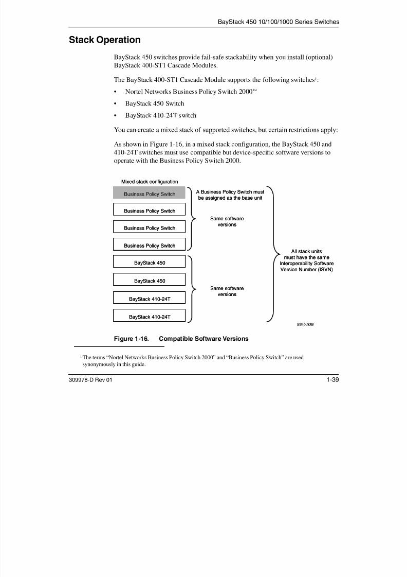
7/23/2019 Baystack 450
http://slidepdf.com/reader/full/baystack-450 71/399
309978-D Rev 01 1-39
The BayStack 400-ST1 Cascade Module supports the following switches1:
• Nortel Networks Business Policy Switch 2000™
• BayStack 450 Switch
• BayStack 410-24T switch
You can create a mixed stack of supported switches, but certain restrictions apply:
As shown in Figure 1-16, in a mixed stack configuration, the BayStack 450 and410-24T switches must use compatible but device-specific software versions tooperate with the Business Policy Switch 2000.
Figure 1-16. Compatible Software Versions
1 The terms “Nortel Networks Business Policy Switch 2000” and “Business Policy Switch” are used
synonymously in this guide.
All stack units
must have the same
Interoperability Software
Version Number (ISVN)
Mixed stack configuration
BS45083B
BayStack 450
BayStack 410-24T
BayStack 450
BayStack 410-24T
Same software
versions
Same software
versions
A Business Policy Switch must
be assigned as the base unit
Business Policy Switch
Business Policy Switch
Business Policy Switch
Business Policy Switch

7/23/2019 Baystack 450
http://slidepdf.com/reader/full/baystack-450 72/399
BayStack 450 10/100/1000 Series Switches
BayStack 400-ST1 Cascade Module
The front-panel components of the BayStack 400-ST1 Cascade Module are shownin Figure 1-17. Component descriptions follow the figure.

7/23/2019 Baystack 450
http://slidepdf.com/reader/full/baystack-450 73/399
309978-D Rev 01 1-41
Figure 1-17. BayStack 400-ST1 Front-Panel Components
Cascade A Out Connector
Provides an attachment point for connecting this unit to another unit via the
cascade cable. A return cable from another unit’s Cascade A Out connector to thisunit’s Cascade A In connector completes the stack connection (see the exampleshown in Figure 1-18).
Unit Select Switch
The Unit Select switch (up = Base) determines the base unit for the stack
configuration (see “Base Unit” on page 1-43). The Unit Select switch status isdisplayed on the BayStack 450 LED display panel. When the Unit Select switch isin the Base (up) position, all other Unit Select switches in the stack configurationmust be set to Off (down).
Cascade A Out Cascade A InUnit SelectBase
1 = Blank connectors (unused)2 = Cascade A Out connector3 = Unit Select switch
4 = Cascade A In connector
3
BS0031B
4
1
2
Using the BayStack 450 10/100/1000 Series Switch
Cascade A In Connector
Provides an attachment point for accepting a cascade cable connection from anadjacent unit in the stack. A return cable from this unit’s Cascade A Out connector
to the adjacent unit’s Cascade A In connector completes the stack connection (see

7/23/2019 Baystack 450
http://slidepdf.com/reader/full/baystack-450 74/399
1-42 309978-D Rev 01
to the adjacent unit s Cascade A In connector completes the stack connection (seethe example shown in Figure 1-18).
Figure 1-18. Connecting Cascade Cables
Note: For stacking three or more units (maximum 8 units per stack), order theoptional 1 meter (3.28 ft) cascade return cable (Order No. AL2018001).
Cascade A Out
Unit 1
Cascade A Out Cascade A In
Unit 2
1 = Base unit2 = 303978-A cascade cable
3 = 303978-A cascade cable (used for return)BS0032B
Cascade A InUnit Select
Cascade A Out Cascade A InUnit Select
3 2
1
BayStack 450 10/100/1000 Series Switches
Base Unit
The base unit is the unique stack unit that you configure with the Unit Selectswitch on the front panel of the 400-ST1 Cascade Module (see “Unit Select
Switch” on page 1-41)
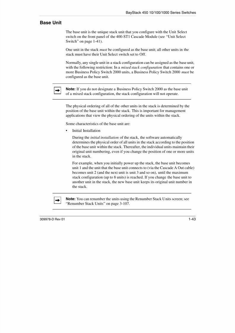
7/23/2019 Baystack 450
http://slidepdf.com/reader/full/baystack-450 75/399
309978-D Rev 01 1-43
Switch on page 1-41).
One unit in the stack must be configured as the base unit; all other units in thestack must have their Unit Select switch set to Off.
Normally, any single unit in a stack configuration can be assigned as the base unit,with the following restriction: In a mixed stack configuration that contains one ormore Business Policy Switch 2000 units, a Business Policy Switch 2000 must beconfigured as the base unit.
The physical ordering of all of the other units in the stack is determined by theposition of the base unit within the stack. This is important for managementapplications that view the physical ordering of the units within the stack.
Some characteristics of the base unit are:
• Initial Installation
During the initial installation of the stack, the software automatically
determines the physical order of all units in the stack according to the positionof the base unit within the stack. Thereafter, the individual units maintain theiroriginal unit numbering, even if you change the position of one or more unitsin the stack.
For example, when you initially power up the stack, the base unit becomesunit 1 and the unit that the base unit connects to (via the Cascade A Out cable)becomes unit 2 (and the next unit is unit 3 and so on), until the maximum
stack configuration (up to 8 units) is reached. If you change the base unit toanother unit in the stack, the new base unit keeps its original unit number inthe stack.
Note: If you do not designate a Business Policy Switch 2000 as the base unitof a mixed stack configuration, the stack configuration will not operate.
Note: You can renumber the units using the Renumber Stack Units screen; see“Renumber Stack Units” on page 3-107.

7/23/2019 Baystack 450
http://slidepdf.com/reader/full/baystack-450 76/399
BayStack 450 10/100/1000 Series Switches
• Stack MAC Address
The Stack MAC address is assigned automatically during the stackinitialization. The base unit’s MAC address, with an offset, is used for the
Stack MAC address.F l if h b i ’ MAC dd i

7/23/2019 Baystack 450
http://slidepdf.com/reader/full/baystack-450 77/399
309978-D Rev 01 1-45
For example, if the base unit’s MAC address is:
00-00-82-99-44-00
and the offset is:
1F
then the Stack MAC address becomes:00-00-82-99-44-1F
If you designate another unit in the stack as the base unit, the MAC address of the new base unit (with offset) now applies to the stack configuration.
The original stack IP address still applies to the new base unit.
Stack Configurations
As shown in Figure 1-19, the cascade connectors and cables on the 400-ST1 frontpanel provide the ability to stack up to eight supported switches.
With BayStack 400-4TX MDAs installed in each switch, the stack canaccommodate a maximum of 224 switch ports.
Because stack parameters are associated with the base unit (see “Base Unit” onpage 1-43), the physical stack order depends on the base unit’s position andwhether the stack is configured as a stack up or a stack down configuration.
The following two sections explain the differences between stack up and stackdown configurations.
Using the BayStack 450 10/100/1000 Series Switch
Stack Up Configurations
In Figure 1-19, data flows from the base unit (unit 1) to the next switch, which isassigned as unit 2, and continues until the last switch in the stack is assigned as
unit 8. The physical order of the switches is from bottom to top (unit 1 to unit 8).

7/23/2019 Baystack 450
http://slidepdf.com/reader/full/baystack-450 78/399
1-46 309978-D Rev 01
p y ( )
Figure 1-19. Stack Up Configuration Example
Stack Down Configurations
In Figure 1-20, data flows from the base unit (unit 1) to the next switch, which isassigned as unit 2, and continues until the last switch in the stack is assigned asunit 8. The physical order of the switches is from top to bottom (unit 1 to unit 8).
Unit 7
Unit 8
1 = Last unit2 = Base unit3 = Cascade cable (PN 303978-A)
4 = Cascade max-return cable (PN 303979-A)
BS0033B
Unit 5
Unit 6
Unit 3
Unit 4
Unit 1
Unit 2
2
1
3
O u t
I n
4
BayStack 450 10/100/1000 Series Switches
Unit 2
Unit 11 In
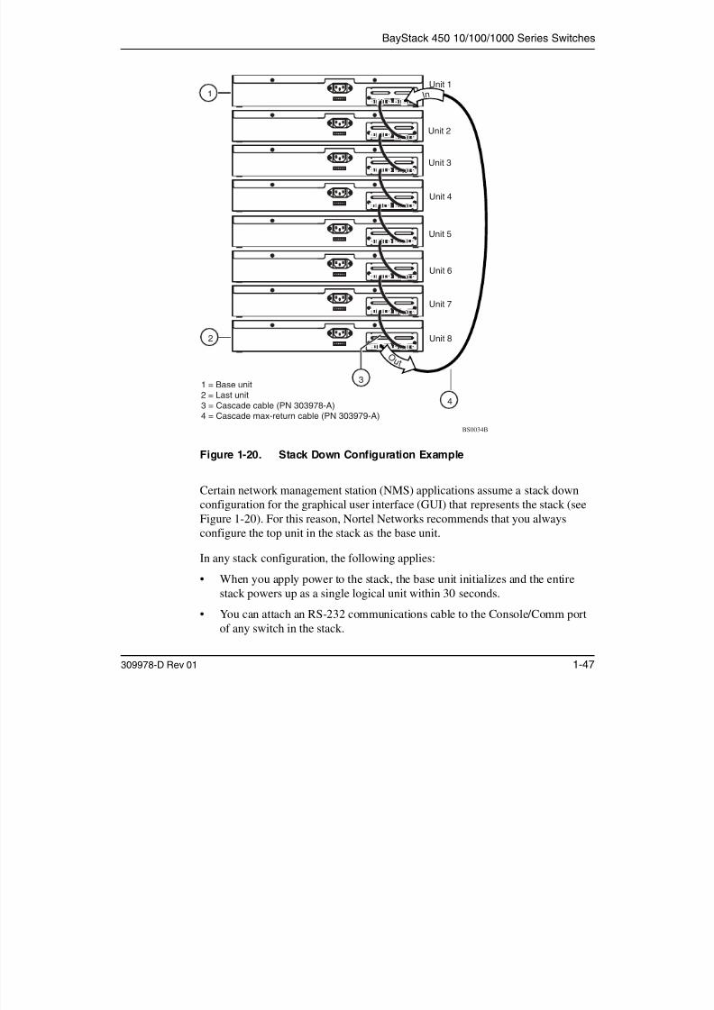
7/23/2019 Baystack 450
http://slidepdf.com/reader/full/baystack-450 79/399
309978-D Rev 01 1-47
Figure 1-20. Stack Down Configuration Example
Certain network management station (NMS) applications assume a stack downconfiguration for the graphical user interface (GUI) that represents the stack (seeFigure 1-20). For this reason, Nortel Networks recommends that you alwaysconfigure the top unit in the stack as the base unit.
In any stack configuration, the following applies:
• When you apply power to the stack, the base unit initializes and the entirestack powers up as a single logical unit within 30 seconds.
• You can attach an RS-232 communications cable to the Console/Comm portof any switch in the stack.
1 = Base unit2 = Last unit
3 = Cascade cable (PN 303978-A)4 = Cascade max-return cable (PN 303979-A)
BS0034B
Unit 4
Unit 3
Unit 6
Unit 5
Unit 8
Unit 7
2
O u t
4
3
Using the BayStack 450 10/100/1000 Series Switch
• You can downline upgrade the entire stack from any switch in the stack.
• You can access and manage the stack using a TELNET connection or anygeneric SNMP management tool through any switch port that is part of thestack configuration.
• When stacking three or more switches use the longer (1-meter) cascade

7/23/2019 Baystack 450
http://slidepdf.com/reader/full/baystack-450 80/399
1-48 309978-D Rev 01
When stacking three or more switches, use the longer (1 meter) cascademax-return cable (PN 303979-A) to complete the link from the last unit in thestack to the base unit.
Redundant Cascade Stacking Feature
BayStack 450 switches allow you to connect up to eight units in a redundantcascade stack. If any single unit fails or if a cable is accidently disconnected, otherunits in the stack remain operational, without interruption.
Figure 1-21 shows an example of how a stack configuration reacts to a failed orpowered-down unit in the stack configuration:
1. As shown in Figure 1-21, unit 3 becomes nonoperational.
This can be the result of a failed unit, or simply because the unit was powereddown.
2. Unit 2 and unit 4, directly upstream and downstream from unit 3, sense theloss of link signals from unit 3.
a. Units 2 and 4 automatically loop their internal stack signals (A and B).
b. The Cas Up LED for unit 2 and the Cas Dwn LED for unit 4 turn on(yellow) to indicate that the stack signals are looped.
3. The remaining stack units remain connected.
Although the example shown in Figure 1-21 shows a failed unit causing the stackto loop signals at the points of failure (A and B), the system reacts the same way if a cable is removed.
BayStack 450 10/100/1000 Series Switches
Cascade A Out Cascade A In
Unit 1
1

7/23/2019 Baystack 450
http://slidepdf.com/reader/full/baystack-450 81/399
309978-D Rev 01 1-49
Figure 1-21. Redundant Cascade Stacking Feature
Virtual Local Area Networks (VLANs)
In a traditional shared-media network, traffic generated by a station is propagatedto all other stations on the local segment. Therefore, for any given station on theshared Ethernet, the local segment is the collision domain because traffic on the
segment has the potential to cause an Ethernet collision. The local segment is alsothe broadcast domain because any broadcast is sent to all stations on the localsegment. Although Ethernet switches and bridges divide a network into smallercollision domains, they do not affect the broadcast domain. In simple terms, avirtual local area network provides a mechanism to fine-tune broadcast domains.
Unit 2
1 = Base unit
2 = Last unit3 = Cascade cable (PN 303978-A)4 = Cascade max-return cable (PN 303979-A)
BS0035B
Unit 5
Unit 4
Unit 3
2
B
A
43

7/23/2019 Baystack 450
http://slidepdf.com/reader/full/baystack-450 82/399
BayStack 450 10/100/1000 Series Switches
The BayStack 450 switch allows you to assign ports to VLANs using the console,TELNET, or any generic SNMP-based network management software. You canassign different ports (and therefore the devices attached to these ports) todifferent broadcast domains. This feature allows network flexibility because you
can reassign VLANs to accommodate network moves, additions, and changes,eliminating the need to change physical cabling.

7/23/2019 Baystack 450
http://slidepdf.com/reader/full/baystack-450 83/399
309978-D Rev 01 1-51
g g p y g
Figure 1-22. Port-Based VLAN Example
BayStack 450-24Tswitch
VLAN 1 VLAN 2
BS45009A
Using the BayStack 450 10/100/1000 Series Switch
IEEE 802.1Q Tagging
BayStack 450 switches operate in accordance with the IEEE 802.1Q taggingrules. Important terms used with the 802.1Q tagging feature are:
• VLAN identifier (VID) -- the 12-bit portion of the VLAN tag in the frameheader that identifies an explicit VLAN
7/23/2019 Baystack 450
http://slidepdf.com/reader/full/baystack-450 84/399
1-52 309978-D Rev 01
header that identifies an explicit VLAN.
• Port VLAN identifier (PVID) -- a classification mechanism that associates aport with a specific VLAN (see Figures 1-24 to 1-29).
• Tagged frame -- the 32-bit field (VLAN tag) in the frame header that identifiesthe frame as belonging to a specific VLAN. Untagged frames are marked
(tagged) with this classification as they leave the switch through a port that isconfigured as a tagged port.
• Untagged frame -- a frame that does not carry any VLAN tagginginformation in the frame header.
• VLAN port members -- a set of ports that form a broadcast domain for aspecific VLAN. A port can be a member of one or more VLANs.
• Untagged member -- a port that has been configured as an untagged memberof a specific VLAN. When an untagged frame exits the switch through anuntagged member port, the frame header remains unchanged. When a taggedframe exits the switch through an untagged member port, the tag is strippedand the tagged frame is changed to an untagged frame.
• Tagged member -- a port that has been configured as a member of a specificVLAN. When an untagged frame exits the switch through a tagged memberport, the frame header is modified to include the 32-bit tag associated with theVLAN assigned to that frame. When a tagged frame exits the switch through atagged member port, the frame header remains unchanged (original VIDremains).
• User_priority -- a three-bit field in the header of a tagged frame. The field isinterpreted as a binary number, and therefore has a value of 0 through 7. Thisfield allows the tagged frame to carry the user_priority value across bridgedLANs where the individual LAN segments may be unable to signal priorityinformation.
• Port priority -- the priority level assigned to untagged frames received on aport. This value becomes the frame’s user_priority value. Tagged packets gettheir user_priority value from the 802.1Q frame header.
BayStack 450 10/100/1000 Series Switches
• Unregistered packet -- a tagged frame that contains a VID where the receivingport is not a member of that VLAN.
• Filtering database identifier (FID) -- the specific filtering/forwarding databasewithin the BayStack 450 switch that is assigned to each VLAN. The currentversion of software assigns all VLANs to the same FID. This is referred to asShared VLAN Learning in the IEEE 802.1Q specification.

7/23/2019 Baystack 450
http://slidepdf.com/reader/full/baystack-450 85/399
309978-D Rev 01 1-53
Shared VLAN Learning in the IEEE 802.1Q specification.
The default configuration settings for BayStack 450 switches have all ports set asuntagged members of VLAN 1 with all ports configured as PVID = 1. EveryVLAN is assigned a unique VLAN identifier (VID) that distinguishes it from allother VLANs. In the default configuration example shown in Figure 1-23, all
incoming packets are assigned to VLAN 1 by the default port VLAN identifier(PVID = 1). Untagged packets enter and leave the switch unchanged.
Figure 1-23. Default VLAN Settings
Port 1
DA
SA
Data
CRC
Incominguntagged
packet
BS45010A
Port 2 Port 3 Port 4 Port 5
VLAN 1
802.1Q Switch
By default:
Key
All ports are assigned PVID = 1
All ports are untagged members of VLAN 1
PVID = 1
Port 6 Port 7 Port 8
DA
SA
Data
CRC
Outgoinguntagged packet
(unchanged)
Using the BayStack 450 10/100/1000 Series Switch
When configuring VLANs, you configure the switch ports as tagged or untagged members of specific VLANs (see Figures 1-24 to 1-29).
In Figure 1-24, untagged incoming packets are assigned directly to VLAN 2
(PVID = 2). Port 5 is configured as a tagged member of VLAN 2, and port 7 isconfigured as an untagged member of VLAN 2.

7/23/2019 Baystack 450
http://slidepdf.com/reader/full/baystack-450 86/399
1-54 309978-D Rev 01
Figure 1-24. Port-Based VLAN Assignment
Port 6
DASADataCRC
BS45011A
Port 7 Port 8
Port 1
P o r t 4
P o r t 5
Port 2 Port 3
802.1Q Switch
PVID = 2
Untagged packet
Untagged memberof VLAN 2
Tagged memberof VLAN 2
Before

7/23/2019 Baystack 450
http://slidepdf.com/reader/full/baystack-450 87/399
Using the BayStack 450 10/100/1000 Series Switch
As shown in Figure 1-27, the untagged packet is marked (tagged) as it leaves theswitch through port 5, which is configured as a tagged member of VLAN 3. Theuntagged packet remains unchanged as it leaves the switch through port 7, whichis configured as an untagged member of VLAN 3.
Port 1 Port 2 Port 3Tagged memberIP Protocol VLAN = 3

7/23/2019 Baystack 450
http://slidepdf.com/reader/full/baystack-450 88/399
1-56 309978-D Rev 01
Figure 1-27. 802.1Q Tagging (After Protocol-Based VLAN Assignment)
BS45085A
Port 6 Port 7 Port 8
Port 1
P o r t 4
P o r t 5
Port 2 Port 3
802.1Q Switch
Key
Priority
CFI
VID
- User_priority
- Canonical format indicator
- VLAN identifier
PVID = 2gg
of VLAN 3
Untagged memberof VLAN 3
After
DA
SA
Data
CRC
(*Recalculated)
Outgoinguntagged packet
(unchanged)
DASADataCRC* Tag
VID = 3Priority
16 bits 3 bits 1 bit 12 bits
8100 CFI
BayStack 450 10/100/1000 Series Switches
In Figure 1-28, tagged incoming packets are assigned directly to VLAN 2 becauseof the tag assignment in the packet. Port 5 is configured as a tagged member of VLAN 2, and port 7 is configured as an untagged member of VLAN 2.
Tagged packet
Port 1 Port 2 Port 3PVID = 2 Tagged memberof VLAN 2

7/23/2019 Baystack 450
http://slidepdf.com/reader/full/baystack-450 89/399
309978-D Rev 01 1-57
Figure 1-28. 802.1Q Tag Assignment
As shown in Figure 1-29, the tagged packet remains unchanged as it leaves theswitch through port 5, which is configured as a tagged member of VLAN 2.However, the tagged packet is stripped (untagged) as it leaves the switch throughport 7, which is configured as an untagged member of VLAN 2.
Figure 1-29. 802.1Q Tagging (After 802.1Q Tag Assignment)
Port 6
DASATagDataCRC
gg p
BS45013A
Port 7 Port 8
P o r t 4
P o r t 5
802.1Q Switch
Untagged member
of VLAN 2
Before
BS45014A
Port 6 Port 7 Port 8
Port 1
P o r t 4
P o r t 5
Port 2 Port 3
802.1Q Switch
KeyPriority
CFI
VID
- User_priority
- Canonical format indicator
- VLAN identifier
PVID = 2 Tagged memberof VLAN 2
Untagged memberof VLAN 2
After
DA
SA
Data
CRC* (*Recalculated)
Outgoinguntagged packet
changed(tag removed)
DASADataCRC Tag
VID = 2Priority
16 bits 3 bits 1 bit 12 bits
8100 CFI
Using the BayStack 450 10/100/1000 Series Switch
VLANs Spanning Multiple Switches
You can use VLANs to segment a network within a switch. When connectingmultiple switches, it is possible to connect users of one VLAN with users of that
same VLAN in another switch. However, the configuration guidelines depend onwhether both switches support 802.1Q tagging.

7/23/2019 Baystack 450
http://slidepdf.com/reader/full/baystack-450 90/399
1-58 309978-D Rev 01
With 802.1Q tagging enabled on a port for a VLAN, all frames leaving the port forthat VLAN are marked as belonging to that specific VLAN. You can assignspecific switch ports as members of one or more VLANs that span multipleswitches, without interfering with the spanning tree protocol.
VLANs Spanning Multiple 802.1Q Tagged Switches
Figure 1-30 shows VLANs spanning two BayStack 450 switches. The 802.1Qtagging is enabled on S1, port 2 and on S2, port 1 for VLAN 1 and VLAN 2. Bothports are tagged members of VLAN 1 and VLAN 2.
Figure 1-30. VLANs Spanning Multiple 802.1Q Tagged Switches
VLAN 1
S1
S2
VLAN 2
BayStack 450-24T
Both ports are tagged
members of VLAN 1and VLAN 2
BayStack 450-24T
B45015A
BayStack 450 10/100/1000 Series Switches
Because there is only one link between the two switches, the Spanning TreeProtocol (STP) treats this configuration as any other switch-to-switch connection.For this configuration to work properly, both switches must support the 802.1Qtagging protocol.
VLANs Spanning Multiple Untagged Switches

7/23/2019 Baystack 450
http://slidepdf.com/reader/full/baystack-450 91/399
309978-D Rev 01 1-59
Figure 1-31 shows VLANs spanning multiple untagged switches. In thisconfiguration switch S2 does not support 802.1Q tagging and you must use asingle switch port on each switch for each VLAN.
For this configuration to work properly, you must set spanning tree participation
to Disabled (the STP is not supported across multiple LANs).
Figure 1-31. VLANs Spanning Multiple Untagged Switches
When the STP is enabled on these switches, only one link between each pair of switches will forward traffic. Because each port belongs to only one VLAN at atime, connectivity on the other VLAN is lost. Exercise care when configuring theswitches to ensure that the VLAN configuration does not conflict with spanningtree configuration.
VLAN 1
S1
S2
VLAN 2
BayStack 450-24T
Untagged portsUntagged ports
Non-802.1Q
tagging switch
BS45016A
Using the BayStack 450 10/100/1000 Series Switch
To connect multiple VLANs across switches with redundant links, you mustdisable the STP on all participating switch ports. Figure 1-32 shows possibleconsequences of enabling the STP when using VLANs between untagged(non-802.1Q tagged) switches.
Station A

7/23/2019 Baystack 450
http://slidepdf.com/reader/full/baystack-450 92/399
1-60 309978-D Rev 01
Figure 1-32. Possible Problems with VLANs and Spanning Tree Protocol
As shown in Figure 1-32, with STP enabled, only one connection between S1 andS2 is forwarding at any time. Communications failure occurs between VLAN 2 of S1 and VLAN 2 of S2, blocking communications between Stations A and B.
The STP selects the link connecting VLAN 1 on Switches S1 and S2 as theforwarding link based on port speed, duplex mode, and port priority. Because theother link connecting VLAN 2 is in the Blocking state, stations on VLAN 2 inswitch S1 cannot communicate with stations in VLAN 2 on switch S2. Withmultiple links, only one link will be in the Forwarding state.
S2
S1
VLAN 1 VLAN 2
VLAN 1 VLAN 2
BlockingNo
Communications
Station B
Forwarding
Non-802.1Q tagged switch
Non-802.1Q tagged switch
BS45017A
BayStack 450 10/100/1000 Series Switches
Shared Servers
BayStack 450 switches allow ports to exist in multiple VLANs for sharedresources, such as servers, printers, and switch-to-switch connections. It is also
possible to have resources exist in multiple VLANs on one switch as shown inFigure 1-33.
In this example clients on different broadcast domains share resources The

7/23/2019 Baystack 450
http://slidepdf.com/reader/full/baystack-450 93/399
309978-D Rev 01 1-61
In this example, clients on different broadcast domains share resources. Thebroadcasts from ports configured in VLAN 3 can be seen by all VLAN portmembers of VLAN 3.
Figure 1-33. Multiple VLANs Sharing Resources
In the above configuration, all of the switch ports are set to participate as VLANport members. This allows the switch to establish the appropriate broadcastdomains within the switch (see Figure 1-34).
BayStack 450-12T switch
BS45018A
S1
V2 V2 V1 V1V2V3
Key
VLAN 1 (PVID=1)
VLAN 2 (PVID=2)
VLAN 3 (PVID=3)
Using the BayStack 450 10/100/1000 Series Switch
VLAN 3
VLAN 2 VLAN 1
S1

7/23/2019 Baystack 450
http://slidepdf.com/reader/full/baystack-450 94/399
1-62 309978-D Rev 01
Figure 1-34. VLAN Broadcast Domains Within the Switch
For example, to create a broadcast domain for each VLAN shown in Figure 1-34,configure each VLAN with a port membership, and each port with the appropriatePVID/VLAN association:
• Ports 8, 6, and 11 are untagged members of VLAN 1.
The PVID/VLAN association for ports 6 and 11 is: PVID = 1.
• Ports 2, 4, 10, and 8 are untagged members of VLAN 2.
The PVID/VLAN association for ports 2, 4, and 10 is: PVID = 2.
• Ports 2, 4, 10, 8, 6, and 11 are untagged members of VLAN 3.
The PVID/VLAN association for port 8 is: PVID = 3.
The following steps show how to use the VLAN configuration screens toconfigure the VLAN 3 broadcast domain shown in Figure 1-34.
Port 2
BS45019A
Port 4 Port 10 Port 8
V2 V2 V2 V1 V2
Key
VLAN 1 (PVID = 1)
VLAN 2 (PVID = 2)
VLAN 3 (PVID = 3)
PVID = 2 PVID = 3
V3
PVID = 1
Port 11Port 6
BayStack 450 10/100/1000 Series Switches
To configure the VLAN port membership for VLAN 1:
1. Select Switch Configuration from the BayStack 450-12T Main Menu (or press w).
2. From the Switch Configuration Menu, select VLAN Configuration
(or press v).
3. From the VLAN Configuration Menu select VLAN Configuration

7/23/2019 Baystack 450
http://slidepdf.com/reader/full/baystack-450 95/399
309978-D Rev 01 1-63
(or press v).
The default VLAN Configuration screen opens (Figure 1-35):
Figure 1-35. Default VLAN Configuration Screen Example
The VLAN Configuration screen settings shown in Figure 1-35 are defaultsettings with all switch ports classified as untagged members of VLAN 1.
Figure 1-36 shows the VLAN Configuration screen after it is configured tosupport the VLAN 3 broadcast domain shown in Figure 1-34 (VLAN Name isoptional).
VLAN Configuration
Create VLAN: [ 1 ] VLAN Type: [ Port-Based ]Delete VLAN: [ ] Protocol Id (PID): [ None ]VLAN Name: [ VLAN #1 ] User-Defined PID: [ 0x0000 ]Management VLAN: [ Yes ] VLAN State: [ Active ]
Port Membership1-6 7-12
------ ------
Unit #1 UUUUUU UUUUUU
KEY: T = Tagged Port Member, U = Untagged Port Member, - = Not a Member of VLANUse space bar to display choices, press <Return> or <Enter> to select choice.Press Ctrl-R to return to previous menu. Press Ctrl-C to return to Main Menu.
Using the BayStack 450 10/100/1000 Series Switch
Ports 2, 4, 6, 8, 10, and 11 are now untagged members of VLAN 3 as shown inFigure 1-34 on page 1-62.
VLAN Configuration
Create VLAN: [ 3 ] VLAN Type: [ Port-Based ]Delete VLAN: [ ] Protocol Id (PID): [ None ]

7/23/2019 Baystack 450
http://slidepdf.com/reader/full/baystack-450 96/399
1-64 309978-D Rev 01
Figure 1-36. VLAN Configuration Screen Example
To configure the PVID (port VLAN identifier) for Port 8:
1. From the VLAN Configuration screen, press [Ctrl]-R to return to the
VLAN Configuration Menu.
2. From the VLAN Configuration Menu, select VLAN Port Configuration
(or press c).
The default VLAN Port Configuration screen opens (Figure 1-37).The VLAN Port Configuration screen settings shown in Figure 1-37 are defaultsettings.
VLAN Name: [ Glenn’s VLAN ] User-Defined PID: [ 0x0000 ]Management VLAN: [ Yes ] VLAN State: [ Active ]
Port Membership
1-6 7-12------ ------
Unit #1 -U-U-U -U-UU-
KEY: T = Tagged Port Member, U = Untagged Port Member, - = Not a Member of VLANUse space bar to display choices, press <Return> or <Enter> to select choice.Press Ctrl-R to return to previous menu. Press Ctrl-C to return to Main Menu.
BayStack 450 10/100/1000 Series Switches
VLAN Port Configuration
Unit: [ 1 ]Port: [ 1 ]Filter Tagged Frames: [ No ]Filter Untagged Frames: [ No ]Filter Unregistered Frames: [ No ]
[ i 1 1 ]

7/23/2019 Baystack 450
http://slidepdf.com/reader/full/baystack-450 97/399
309978-D Rev 01 1-65
Figure 1-37. Default VLAN Port Configuration Screen Example
Figure 1-38 shows the VLAN Port Configuration screen after it is configured tosupport the PVID assignment for port 8 (as shown in Figure 1-34). The Port Namefield is optional.
As shown in Figure 1-38, the PVID/VLAN association for VLAN 3 is now PVID = 3.
Port Name: [ Unit 1, Port 1 ]PVID: [ 1 ]Port Priority: [ 0 ]Tagging: [ Untagged Access ]
AutoPVID (all ports): [ Disabled ]
Use space bar to display choices, press <Return> or <Enter> to select choice.Press Ctrl-R to return to previous menu. Press Ctrl-C to return to Main Menu.
Using the BayStack 450 10/100/1000 Series Switch
VLAN Port Configuration
Unit: [ 1 ]Port: [ 8 ]Filter Tagged Frames: [ No ]Filter Untagged Frames: [ No ]Filter Unregistered Frames: [ No ]

7/23/2019 Baystack 450
http://slidepdf.com/reader/full/baystack-450 98/399
1-66 309978-D Rev 01
Figure 1-38. VLAN Port Configuration Screen Example
The preceding example explains how to manually configure the PVID/VLANassociation to PVID 3. However, if you set the AutoPVID field value to Enabledbefore creating the VLAN port memberships, the PVID/VLAN association isautomatically assigned a value that is associated with the VLAN number youcreate.
See “VLAN Port Configuration” on page 3-52, for more information.
Note: You can also automatically assign a PVID/VLAN association for eachVLAN port membership you create.
g [ ]Port Name: [ Dan’s port ]PVID: [ 3 ]Port Priority: [ 0 ]Tagging: [ Untagged Access ]
AutoPVID (all ports): [ Disabled ]
Use space bar to display choices, press <Return> or <Enter> to select choice.
Press Ctrl-R to return to previous menu. Press Ctrl-C to return to Main Menu.
BayStack 450 10/100/1000 Series Switches
VLAN Workgroup Summary
This section summarizes the VLAN workgroup examples discussed in theprevious sections of this chapter. As shown in Figure 1-39, switch S1 (a BayStack
450 switch) is configured with multiple VLANs:

7/23/2019 Baystack 450
http://slidepdf.com/reader/full/baystack-450 99/399
309978-D Rev 01 1-67
Figure 1-39. VLAN Configuration Spanning Multiple Switches
• Ports 1, 6, 11, and 12 are in VLAN 1.
• Ports 2, 3, 4, 7, and 10 are in VLAN 2.
• Port 8 is in VLAN 3.
BayStack 450-24T
Untagged ports
(STP disabled)
Both ports are taggedmembers of VLAN 1
and VLAN 2
BayStack 450-24TNon-802.1Qtagging switch
BS45020A
Key
VLAN 1 (PVID=1)
VLAN 2 (PVID=2)
VLAN 3 (PVID=3)
S1
S2S4
S3
V1
V2 V2 V1 V2V3
Non-802.1Qtagging switch
Using the BayStack 450 10/100/1000 Series Switch
Because S4 does not support 802.1Q tagging, a single switch port on each switchmust be used for each VLAN (see “VLANs Spanning Multiple UntaggedSwitches” on page 1-59).
The connection to S2 requires only one link between the switches because S1 andS2 are both BayStack 450 switches that support 802.1Q tagging (see “VLANsSpanning Multiple 802.1Q Tagged Switches” on page 1-58).

7/23/2019 Baystack 450
http://slidepdf.com/reader/full/baystack-450 100/399
1-68 309978-D Rev 01
VLAN Configuration Rules
VLANs operate according to specific configuration rules. When creating VLANs,consider the following rules that determine how the configured VLAN reacts inany network topology:
• Your switch supports up to 64 VLANs. You can create port-based VLANs andprotocol-based VLANs, in any combination, as long as you do not exceed atotal of 64 VLANs.
• All ports that are involved in port mirroring must have memberships in thesame VLANs. If a port is configured for port mirroring, the port’s VLAN
membership cannot be changed.• If a port is a trunk group member, all trunk members are added or deleted
from the VLAN.
• All ports involved in trunking and port mirroring must have the same VLANconfiguration. If a port is on a trunk with a mirroring port, the VLANconfiguration cannot be changed.
• VLANs are not dependent on Rate Limiting settings.
• If a port is an IGMP member on any VLAN, and is removed from a VLAN,the port’s IGMP membership is also removed.
• If a port is added to a different VLAN, and it is already configured as a staticrouter port, the port is configured as an IGMP member on that specificVLAN.
For more information about configuring VLANs, see “VLAN ConfigurationMenu” on page 3-44.
See also Appendix E, “Quick Steps to Features,” for configuration flowcharts thatcan help you use this feature.
BayStack 450 10/100/1000 Series Switches
IGMP Snooping
BayStack 450 switches can sense Internet Group Management Protocol (IGMP)host membership reports from attached stations. The switches use this information
to set up a dedicated path between the requesting station and a local IP multicastrouter. After the pathway is established, the BayStack 450 switch blocks the IPmulticast stream from exiting any other port that does not connect to another hostmember, thus conserving bandwidth. The following discussion describes how

7/23/2019 Baystack 450
http://slidepdf.com/reader/full/baystack-450 101/399
309978-D Rev 01 1-69
g gBayStack 450 switches provide the same benefit as IP multicast routers, but in thelocal area.
IP multicast routers use IGMP to learn about the existence of host group memberson their directly attached subnets (see RFC 2236). The IP multicast routers getthis information by broadcasting IGMP queries and listening for IP hostsreporting their host group memberships. This process is used to set up a client/ server relationship between an IP multicast source that provides the data streamsand the clients that want to receive the data.
Figure 1-40 shows how IGMP is used to set up the path between the client and
server. As shown in this example, the IGMP host provides an IP multicast streamto designated routers that forward the IP multicast stream on their local networkonly if there is a recipient.
The client/server path is set up as follows:
1. The designated router sends out a host membership query to the subnet andreceives host membership reports from end stations on the subnet.
2. The designated routers then set up a path between the IP multicast streamsource and the end stations.
3. Periodically, the router continues to query end stations on whether to continueparticipation.
4. As long as any client continues to participate, all clients, includingnonparticipating end stations on that subnet, receive the IP multicast stream.
IP multicast can be optimized in a LAN by using IP multicast filtering switches, such as the BayStack 450 switch.
Note: Although the nonparticipating end stations can filter the IP multicasttraffic, the IP multicast still exists on the subnet and consumes bandwidth.
Using the BayStack 450 10/100/1000 Series Switch
As shown in Figure 1-40, a non-IP multicast filtering switch causes IP multicasttraffic to be sent to all segments on the local subnet.
Host
membershipquery
IGMPHost Host
membershipquery
Internet
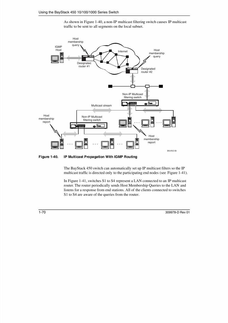
7/23/2019 Baystack 450
http://slidepdf.com/reader/full/baystack-450 102/399
1-70 309978-D Rev 01
Figure 1-40. IP Multicast Propagation With IGMP Routing
The BayStack 450 switch can automatically set up IP multicast filters so the IP
multicast traffic is directed only to the participating end nodes (see Figure 1-41).In Figure 1-41, switches S1 to S4 represent a LAN connected to an IP multicastrouter. The router periodically sends Host Membership Queries to the LAN andlistens for a response from end stations. All of the clients connected to switchesS1 to S4 are aware of the queries from the router.
Non-IP Multicastfiltering switch
Non-IP Multicastfiltering switch
Hostmembership
report
Multicast stream
BS45021B
Designatedrouter #2
Designatedrouter #1
Hostmembership
report
q y
BayStack 450 10/100/1000 Series Switches
One client, connected to S2, responds with a host membership report. Switch S2intercepts the report from that port, and generates a proxy report to its upstreamneighbor, S1. Also, two clients connected to S4 respond with host membershipreports, causing S4 to intercept the reports and to generate a consolidated proxy
report to its upstream neighbor, S1.
Internet

7/23/2019 Baystack 450
http://slidepdf.com/reader/full/baystack-450 103/399
309978-D Rev 01 1-71
Figure 1-41. BayStack 450 Switch Filtering IP Multicast Streams (1 of 2)
Switch S1 treats the consolidated proxy reports from S2 and S4 as if they werereports from any client connected to its ports, and generates a consolidated proxyreport to the designated router. In this way, the router receives a singleconsolidated report from that entire subnet.
Consolidatedreport
BS45022B
Hostmembershipreport
Hostmembership
report
Designatedrouter
Hostmembership
query
Internet
BayStack 450-24TSwitch
BayStack 450-24TSwitches
Proxy
Proxy
BayStack 450-24TSwitch
S2
S4
S1
S3
Using the BayStack 450 10/100/1000 Series Switch
After the switches learn which ports are requesting access to the IP multicaststream, all other ports not responding to the queries are blocked from receiving theIP multicast (Figure 1-42).
Designatedt
Internet

7/23/2019 Baystack 450
http://slidepdf.com/reader/full/baystack-450 104/399
1-72 309978-D Rev 01
Figure 1-42. BayStack 450 Switch Filtering IP Multicast Streams (2 of 2)
The consolidated proxy report generated by the switch remains transparent tolayer 3 of the International Organization for Standardization, Open SystemsInterconnection (ISO/OSI) model. (The switch IP address and MAC address arenot part of proxy report generation.) The last reporting IGMP group member ineach VLAN represents all of the hosts in that VLAN and IGMP group.
BS45023B
router
Hostmembership
query
BayStack 450-24TSwitch
BayStack 450-24TSwitches
BayStack 450-24TSwitch
Key
Multicast stream
S2
S4
S1
S3
BayStack 450 10/100/1000 Series Switches
IGMP Snooping Configuration Rules
The IGMP snooping feature operates according to specific configuration rules.When configuring your switch for IGMP snooping, consider the following rules
that determine how the configuration reacts in any network topology:• A port that is currently configured for EAPOL-based security cannot be
configured as a static router port.
• A port that is currently configured for port mirroring cannot be configured as

7/23/2019 Baystack 450
http://slidepdf.com/reader/full/baystack-450 105/399
309978-D Rev 01 1-73
A port that is currently configured for port mirroring cannot be configured asa static router port.
• If a MultiLink Trunk member is configured as a static router port, all of the
MultiLink Trunk members are configured as static router ports. Also, if astatic router port is removed, and it is a MultiLink Trunk member, allMultiLink Trunk members are automatically removed as static router portmembers.
• Static router ports must be port members of at least one VLAN.
• If a port is configured as a static router port, it is configured as a static routerport for all VLANs on that port. The IGMP configuration is propagatedthrough all VLANs of that port.
• If a static router port is removed, the membership for that port is removedfrom all VLANs of that port.
• The IGMP snooping feature is not STP dependent.
• The IGMP snooping feature is not Rate Limiting dependent.
• The snooping field must be enabled for the proxy field to have any validmeaning.
• Static router ports are configured per VLAN and per IGMP Version.
For more information about using the IGMP snooping feature, see “IGMPConfiguration Menu” on page 3-78.
See also Appendix E, “Quick Steps to Features,” for configuration flowcharts thatcan help you use this feature.
Note: Because IGMP snooping is set up per VLAN, all IGMP changes areimplemented according to the VLAN configuration for the specified ports.
Using the BayStack 450 10/100/1000 Series Switch
IEEE 802.1p Prioritizing
You can use the VLAN Configuration screens to prioritize the order in which theswitch forwards packets, on a per-port basis. For example, if messages from a
specific segment are crucial to your operation, you can set the switch portconnected to that segment to a higher priority level (by default, all switch ports areset to Low priority). When the switch receives untagged packets on that port, theuntagged packets are tagged according to the priority level that you assign to theport (see Figure 1-43)

7/23/2019 Baystack 450
http://slidepdf.com/reader/full/baystack-450 106/399
1-74 309978-D Rev 01
port (see Figure 1-43).
Figure 1-43. Prioritizing Packets
The newly tagged frame is read within the switch and sent to the port’s high or lowtransmit queue for disposition (see Figure 1-44). The port transmit queue exampleshown in Figure 1-44 applies to all ports on the BayStack 450 switch.
BS45024A
Port 6 Port 7 Port 8
Port 1
PVID = 2Priority = 6
P o r t 4
P o r t 5
Port 2 Port 3
802.1Q Switch High
Low
Key
Priority
CFI
VID
- User_priority
- Canonical format indicator
- VLAN identifier
Tagged memberof VLAN 2 (Port 5)
Port configurationparameters
Port 5transmitqueue
Untagged memberof VLAN 2
After
Before
DA
SA
Data
CRC
(*Recalculated)
Outgoinguntagged packet
(unchanged)
DA
SA
Data
CRC
DASADataCRC* Tag
VID = 2Priority = 6
16 bits 3 bits 1 bit 12 bits
8100 CFI
BayStack 450 10/100/1000 Series Switches
U i itPort
High
High prioritypacket
Port 5
Trafficclass
7
654

7/23/2019 Baystack 450
http://slidepdf.com/reader/full/baystack-450 107/399
309978-D Rev 01 1-75
Figure 1-44. Port Transmit Queue
As shown in Figure 1-44, the switch provides two transmission queues, High and Low, for any given port. Frames are assigned to one of these queues on the basis of the user_priority value, using a traffic class table. This table is managed by usingthe Traffic Class Configuration screen (Figure 1-45). The table indicates thecorresponding traffic class that is assigned to the frame, for each possibleuser_priority value. If the frame leaves the switch formatted as a tagged packet,the traffic class assigned to the frame is carried forward to the next 802.1p-capableswitch. This allows the packet to carry the assigned traffic class priority throughthe network until it reaches its destination.
The following steps show how to use the Traffic Class Configuration screen toconfigure the port priority level shown in Figure 1-43.
For more information about using the Traffic Class Configuration screen, see
“Traffic Class Configuration” on page 3-57.
BS45025A
User priority(6)
Porttransmitqueue
3210
Low
Using the BayStack 450 10/100/1000 Series Switch
To configure the port priority level, follow these steps:
1. Determine the priority level you want to assign to the switch port.
User priority levels are assigned default settings in all BayStack 450 switches.The range is from 0 to 7. The traffic class table can be modified; therefore,view the settings shown in the Traffic Class Configuration screen beforesetting the port priority in the VLAN Port Configuration screen.
2. Select Switch Configuration from the BayStack 450-12T Main Menu (or press w).

7/23/2019 Baystack 450
http://slidepdf.com/reader/full/baystack-450 108/399
1-76 309978-D Rev 01
(or press w).
3. From the Switch Configuration Menu, select VLAN Configuration (or press v).
4. From the VLAN Configuration Menu, select Traffic Class Configuration
(or press t).
The Traffic Class Configuration screen opens (Figure 1-45).
Figure 1-45. Default Traffic Class Configuration Screen Example
Traffic Class Configuration
User Priority Traffic Class------------- -------------Priority 0: [ Low ]Priority 1: [ Low ]Priority 2: [ Low ]Priority 3: [ Low ]Priority 4: [ Low ]
Priority 5: [ Low ]Priority 6: [ Low ]Priority 7: [ Low ]
Use space bar to display choices, press <Return> or <Enter> to select choice.Press Ctrl-R to return to previous menu. Press Ctrl-C to return to Main Menu.
BayStack 450 10/100/1000 Series Switches
5. Select a priority level from the range shown in the Traffic Class
Configuration screen (or modify the Traffic Class parameters to suit your
needs).
6. Assign the priority level to ports using the VLAN Port Configuration
screen:
a. Press [Ctrl]-R to return to the VLAN Configuration Menu.
b. From the VLAN Configuration Menu, select VLAN Port
Configuration (or press c).

7/23/2019 Baystack 450
http://slidepdf.com/reader/full/baystack-450 109/399
309978-D Rev 01 1-77
g ( p )
The VLAN Port Configuration screen opens (Figure 1-46).
Figure 1-46 shows the VLAN Port Configuration screen setup for port 4 inFigure 1-43 on page 1-74.
Figure 1-46. Setting Port Priority Example
For more information about using this feature, see “VLAN Configuration Menu”on page 3-44.
VLAN Port Configuration
Port: [ 4 ]
Filter Tagged Frames: [ No ]Filter Untagged Frames: [ No ]Filter Unregistered Frames: [ No ]Port Name: [ Cathy’s port ]PVID: [ 2 ]Port Priority: [ 6 ]Tagging: [ Untagged Access ]
Use space bar to display choices, press <Return> or <Enter> to select choice.Press Ctrl-R to return to previous menu. Press Ctrl-C to return to Main Menu.
Using the BayStack 450 10/100/1000 Series Switch
MultiLink Trunks
A MultiLink Trunk (MLT)1 allows you to group up to four switch ports to form alink to another switch or server. This can increase the aggregate throughput of the
interconnection between devices as much as 800 Mb/s in full-duplex mode (up to8000 Mb/s with optional gigabit MDA ports). You can configure up to sixMultiLink Trunks. The MLT members can reside on a single unit or on multipleunits in the same stack configuration as a distributed trunk . MLT software detectsmisconfigured (or broken) trunk links and redirects traffic on the misconfigured or

7/23/2019 Baystack 450
http://slidepdf.com/reader/full/baystack-450 110/399
1-78 309978-D Rev 01
broken trunk link to other trunk members within that MLT.
You can use the MultiLink Trunk Configuration screen to create switch-to-switch
and switch-to-server MLT links (see Figures 1-47 and 1-48).
Figure 1-47 shows two trunks (T1 and T2) connecting switch S1 to switches S2and S3.
Figure 1-47. Switch-to-Switch Trunk Configuration Example
1 In this guide, the terms “trunk” and “MLT” are used interchangeably to indicate a MultiLink Trunk.
S1
S2
S3
BS45026A
T1
T2
FF
BayStack 450 10/100/1000 Series Switches
You can configure each of the trunks shown in Figure 1-47 with up to four switchports to provide up to 800 Mb/s aggregate bandwidth through each trunk, infull-duplex mode. As shown in this example, when traffic betweenswitch-to-switch connections approaches single port bandwidth limitations,creating a MultiLink Trunk can supply the additional bandwidth required toimprove the performance.
Figure 1-48 shows a typical switch-to-server trunk configuration. In this example,file server FS1 uses dual MAC addresses, using one MAC address for eachnetwork interface controller (NIC) For this reason FS1 does not require a trunk

7/23/2019 Baystack 450
http://slidepdf.com/reader/full/baystack-450 111/399
309978-D Rev 01 1-79
network interface controller (NIC). For this reason, FS1 does not require a trunkassignment. FS2 is a single MAC server (with a four-port NIC) and is set up astrunk configuration T1.
Figure 1-48. Switch-to-Server Trunk Configuration Example
Client/Server Configuration Using MultiLink Trunks
Figure 1-49 shows an example of how MultiLink Trunking can be used in aclient/server configuration. In this example, both servers connect directly toswitch S1. FS2 is connected through a trunk configuration (T1). Theswitch-to-switch connections are through trunks (T2, T3, T4, and T5).
S1
FS1 FS2
T1
BS45027A
Using the BayStack 450 10/100/1000 Series Switch
Clients accessing data from the servers (FS1 and FS2) are provided withmaximized bandwidth through trunks T1, T2, T3, T4, and T5. Trunk members(the ports making up each trunk) do not have to be consecutive switch ports; youcan select ports randomly, as shown by T5.
With spanning tree enabled , one of the trunks (T2 or T3) acts as a redundant(backup) trunk to switch S2. With spanning tree disabled , you must configuretrunks T2 and T3 into separate VLANs for this configuration to function properly(see “IEEE 802.1Q VLAN Workgroups” on page 1-50).

7/23/2019 Baystack 450
http://slidepdf.com/reader/full/baystack-450 112/399
1-80 309978-D Rev 01
Figure 1-49. Client/Server Configuration Example
The trunk configuration screens for switches S1 to S4 are shown in “TrunkConfiguration Screen Examples” following this section. For detailed informationabout configuring trunks, see “MultiLink Trunk Configuration” on page 3-64.
T2
S2
S3T3 T4
F
S4T5
F
S1
BS45028A
FS1 FS2
T1
BayStack 450 10/100/1000 Series Switches
Trunk Configuration Screen Examples
This section shows examples of the MultiLink Trunk configuration screens for theclient/server configuration example shown in Figure 1-49 on page 1-80. Thescreens show how you could set up the trunk configuration screens for switchesS1 to S4. See “Spanning Tree Considerations for MultiLink Trunks” onpage 1-93, and “MultiLink Trunk Configuration” on page 3-64 for moreinformation.
Trunk Configuration Screen for Switch S1

7/23/2019 Baystack 450
http://slidepdf.com/reader/full/baystack-450 113/399
309978-D Rev 01 1-81
Trunk Configuration Screen for Switch S1
Switch S1 is set up with five trunk configurations: T1, T2, T3, T4, and T5.
Setting Up the Trunk Configuration for S1:
To set up the trunk configuration, choose MultiLink Trunk Configuration (or press t) from the MultiLink Trunk Configuration Menu screen (Figure 1-50).
Figure 1-50. Choosing the MultiLink Trunk Configuration Screen
MultiLink Trunk Configuration Menu
MultiLink Trunk Configuration...MultiLink Trunk Utilization...Return to Switch Configuration Menu
Use arrow keys to highlight option, press <Return> or <Enter> to select option.Press Ctrl-R to return to previous menu. Press Ctrl-C to return to Main Menu.
Using the BayStack 450 10/100/1000 Series Switch
The MultiLink Trunk Configuration screen opens (Figure 1-51).
MultiLink Trunk Configuration
Trunk Trunk Members (Unit/Port) STP Learning Trunk Mode Trunk Status----- ------------------------------- ------------ --------------- ------------1 [ /15 ][ /17 ][ /19 ][ /21 ] [ Normal ] Basic [ Enabled ]2 [ /25 ][ /26 ][ / ][ / ] [ Normal ] Basic [ Enabled ]3 [ /2 ][ /4 ][ / ][ / ] [ Normal ] Basic [ Enabled ]4 [ /14 ][ /16 ][ / ][ / ] [ Normal ] Basic [ Enabled ]
[ /22 ][ /24 ][ / ][ / ] [ ] i [ bl d ]

7/23/2019 Baystack 450
http://slidepdf.com/reader/full/baystack-450 114/399
1-82 309978-D Rev 01
Figure 1-51. MultiLink Trunk Configuration Screen for Switch S1
Switch S1 is configured as follows:
• Trunk (read only) indicates the trunks (1 to 6) that correspond to the switchports specified in the Trunk Members fields.
• Trunk Members (Unit/Port) indicates the ports that can be configured, ineach row, to create the corresponding trunk:
-- Ports 15, 17, 19, and 21 are assigned as trunk members of trunk 1.
-- Ports 25 and 26 are assigned as trunk members of trunk 2.
Note: The Unit value (in the Unit/Port field) cannot be configured when the
switch is operating in standalone mode. For detailed information about theMultiLink Trunk Configuration screen fields, see “MultiLink TrunkConfiguration” on page 3-64.
5 [ /22 ][ /24 ][ / ][ / ] [ Fast ] Basic [ Enabled ]6 [ / ][ / ][ / ][ / ] [ Normal ] Basic [ Disabled ]
Trunk Trunk Name----- ------------------1 [ S1:T1 to FS2 ]2 [ S1:T2 to S2 ]3 [ S1:T3 to S2 ]4 [ S1:T4 to S3 ]5 [ S1:T5 to S4 ]6 [ Trunk #6 ]
Enter text, press <Return> or <Enter> when complete.Press Ctrl-R to return to previous menu. Press Ctrl-C to return to Main Menu.
BayStack 450 10/100/1000 Series Switches
-- Ports 2 and 4 are assigned as trunk members of trunk 3.
-- Ports 14 and 16 are assigned as trunk members of trunk 4.
-- Ports 22 and 24 are assigned as trunk members of trunk 5.
• STP Learning indicates the spanning tree participation setting for each of thetrunks:
-- Trunks 1 through 4 are enabled for Normal STP Learning.
-- Trunk 5 is enabled for Fast STP Learning.

7/23/2019 Baystack 450
http://slidepdf.com/reader/full/baystack-450 115/399
309978-D Rev 01 1-83
• Trunk Mode (read only) indicates the Trunk Mode for each of the trunks:
The Trunk Mode field values for trunks 1 to 5 are set to Basic. Source MACaddresses are assigned statically to specific trunk members for flooding andforwarding. This allows the switch to stabilize and distribute the data streamsof source addresses across the trunk members.
• Trunk Status indicates the Trunk Status for each of the trunks. When set toEnabled, the configuration settings for that specific trunk are activated.
• Trunk Name indicates optional fields for assigning names to the
corresponding configured trunks.The names chosen for this example provide meaningful information to theuser of this switch (for example, S1:T1 to FS2 indicates that trunk 1, in switchS1, connects to file server 2).
Using the BayStack 450 10/100/1000 Series Switch
Trunk Configuration Screen for Switch S2
As shown in Figure 1-49 on page 1-80, switch S2 is set up with two trunkconfigurations (T2 and T3). Both trunks connect directly to switch S1.
As in the previous screen examples, to set up a trunk configuration, chooseMultiLink Trunk Configuration from the MultiLink Trunk Configuration Menu.
Figure 1-52 shows the MultiLink Trunk Configuration screen for switch S2.

7/23/2019 Baystack 450
http://slidepdf.com/reader/full/baystack-450 116/399
1-84 309978-D Rev 01
Figure 1-52. MultiLink Trunk Configuration Screen for Switch S2
Switch S2 is configured as follows:
• Trunk (read only) indicates the trunks (1 to 6) that correspond to the switchports specified in the Trunk Members fields.
MultiLink Trunk Configuration
Trunk Trunk Members (Unit/Port) STP Learning Trunk Mode Trunk Status----- ------------------------------- ------------ --------------- ------------1 [ /25 ][ /26 ][ / ][ / ] [ Normal ] Basic [ Enabled ]2 [ /1 ][ /3 ][ / ][ / ] [ Normal ] Basic [ Enabled ]3 [ / ][ / ][ / ][ / ] [ Normal ] Basic [ Disabled ]4 [ / ][ / ][ / ][ / ] [ Normal ] Basic [ Disabled ]5 [ / ][ / ][ / ][ / ] [ Normal ] Basic [ Disabled ]6 [ / ][ / ][ / ][ / ] [ Normal ] Basic [ Disabled ]
Trunk Trunk Name----- ------------------1 [ S2:T2 to S1 ]2 [ S2:T3 to S1 ]3 [ Trunk #3 ]4 [ Trunk #4 ]5 [ Trunk #5 ]6 [ Trunk #6 ]
Enter text, press <Return> or <Enter> when complete.Press Ctrl-R to return to previous menu. Press Ctrl-C to return to Main Menu.
BayStack 450 10/100/1000 Series Switches
• Trunk Members (Unit/Port) indicates the ports that can be configured, ineach row, to create the corresponding trunk:
-- Ports 25 and 26 are assigned as trunk members of trunk 1.
-- Ports 1 and 3 are assigned as trunk members of trunk 2.
• STP Learning indicates the spanning tree participation setting for each of thetrunks:
Trunks 1 and 2 are enabled for Normal STP Learning.
• Trunk Mode (read only) indicates the Trunk Mode for each of the trunks:

7/23/2019 Baystack 450
http://slidepdf.com/reader/full/baystack-450 117/399
309978-D Rev 01 1-85
( y)
The Trunk Mode field values for trunks 1 and 2 are set to Basic. Source MAC
addresses are assigned statically to specific trunk members for flooding andforwarding. This allows the switch to stabilize and distribute the data streamsof source addresses across the trunk members.
• Trunk Status indicates the Trunk Status for each of the trunks. When set toEnabled, the configuration settings for that specific trunk are activated.
• Trunk Name indicates optional fields for assigning names to thecorresponding configured trunks.
The names chosen for this example provide meaningful information to theuser of this switch (for example, S2:T2 to S1 indicates that trunk 1, in switchS2, connects to switch 1).
Using the BayStack 450 10/100/1000 Series Switch
Trunk Configuration Screen for Switch S3
As shown in Figure 1-49 on page 1-80, switch S3 is set up with one trunkconfiguration (T4). This trunk connects directly to switch S1.
As in the previous screen examples, to set up an interswitch trunk configuration,choose MultiLink Trunk Configuration from the MultiLink Trunk ConfigurationMenu.
Figure 1-53 shows the MultiLink Trunk Configuration screen for switch S3.

7/23/2019 Baystack 450
http://slidepdf.com/reader/full/baystack-450 118/399
1-86 309978-D Rev 01
Figure 1-53. MultiLink Trunk Configuration Screen for Switch S3
Switch S3 is configured as follows:
• Trunk (read only) indicates the trunk (1 to 6) that corresponds to the switchports specified in the Trunk Members fields.
• Trunk Members (Unit/Port) indicates the ports that can be configured, ineach row, to create the corresponding trunk:
Ports 1 and 3 are assigned as trunk members of trunk 1.
MultiLink Trunk Configuration
Trunk Trunk Members (Unit/Port) STP Learning Trunk Mode Trunk Status----- ------------------------------- ------------ --------------- ------------1 [ /1 ][ /3 ][ / ][ / ] [ Normal ] Basic [ Enabled ]2 [ / ][ / ][ / ][ / ] [ Normal ] Basic [ Disabled ]3 [ / ][ / ][ / ][ / ] [ Normal ] Basic [ Disabled ]4 [ / ][ / ][ / ][ / ] [ Normal ] Basic [ Disabled ]5 [ / ][ / ][ / ][ / ] [ Normal ] Basic [ Disabled ]6 [ / ][ / ][ / ][ / ] [ Normal ] Basic [ Disabled ]
Trunk Trunk Name----- ------------------1 [ S3:T4 to S1 ]2 [ Trunk #2 ]3 [ Trunk #3 ]4 [ Trunk #4 ]5 [ Trunk #5 ]6 [ Trunk #6 ]
Enter text, press <Return> or <Enter> when complete.Press Ctrl-R to return to previous menu. Press Ctrl-C to return to Main Menu.
BayStack 450 10/100/1000 Series Switches
• STP Learning indicates the spanning tree participation setting for each of thetrunks:
Trunk 1 is enabled for Normal STP Learning.
• Trunk Mode (read only) indicates the Trunk Mode for each of the trunks:
The Trunk Mode field value for trunk 1 is set to Basic. Source MAC addressesare assigned statically to specific trunk members for flooding and forwarding.This allows the switch to stabilize and distribute the data streams of sourceaddresses across the trunk members.
• Trunk Status indicates the Trunk Status for each of the trunks When set to

7/23/2019 Baystack 450
http://slidepdf.com/reader/full/baystack-450 119/399
309978-D Rev 01 1-87
Trunk Status indicates the Trunk Status for each of the trunks. When set toEnabled, the configuration settings for that specific trunk are activated.
• Trunk Name indicates optional fields for assigning names to thecorresponding configured trunks.
The names chosen for this example provide meaningful information to theuser of this switch (for example, S3:T4 to S1 indicates that trunk 1, in switchS3, connects to switch 1).
Using the BayStack 450 10/100/1000 Series Switch
Trunk Configuration Screen for Switch S4
As shown in Figure 1-49, switch S4 is set up with one trunk configuration (T5).This trunk connects directly to switch S1.
As in the previous screen examples, to set up a trunk configuration, chooseMultiLink Trunk Configuration from the MultiLink Trunk Configuration Menu.
Figure 1-54 shows the MultiLink Trunk Configuration screen for switch S4.

7/23/2019 Baystack 450
http://slidepdf.com/reader/full/baystack-450 120/399
1-88 309978-D Rev 01
Figure 1-54. MultiLink Trunk Configuration Screen for Switch S4
MultiLink Trunk Configuration
Trunk Trunk Members (Unit/Port) STP Learning Trunk Mode Trunk Status----- ------------------------------- ------------ --------------- ------------1 [ /5 ][ /11 ][ / ][ / ] [ Normal ] Basic [ Enabled ]2 [ / ][ / ][ / ][ / ] [ Normal ] Basic [ Disabled ]3 [ / ][ / ][ / ][ / ] [ Normal ] Basic [ Disabled ]4 [ / ][ / ][ / ][ / ] [ Normal ] Basic [ Disabled ]5 [ / ][ / ][ / ][ / ] [ Normal ] Basic [ Disabled ]6 [ / ][ / ][ / ][ / ] [ Normal ] Basic [ Disabled ]
Trunk Trunk Name
----- ------------------1 [ S4:T5 to S1 ]2 [ Trunk #2 ]3 [ Trunk #3 ]4 [ Trunk #4 ]5 [ Trunk #5 ]6 [ Trunk #6 ]
Enter text, press <Return> or <Enter> when complete.Press Ctrl-R to return to previous menu. Press Ctrl-C to return to Main Menu.
BayStack 450 10/100/1000 Series Switches
Switch S4 is configured as follows:
• Trunk (read only) indicates the trunks (1 to 6) that correspond to the switchports specified in the Trunk Members fields.
• Trunk Members (Unit/Port) indicates the ports that can be configured, in
each row, to create the corresponding trunk:
Ports 5 and 11 are assigned as trunk members of trunk T1.
• STP Learning indicates the spanning tree participation setting for each of thetrunks:
Trunk 1 is enabled for Normal STP Learning

7/23/2019 Baystack 450
http://slidepdf.com/reader/full/baystack-450 121/399
309978-D Rev 01 1-89
Trunk 1 is enabled for Normal STP Learning.
• Trunk Mode (read only) indicates the Trunk Mode for each of the trunks:The Trunk Mode field value for trunk 1 is set to Basic. Source MAC addressesare assigned statically to specific trunk members for flooding and forwarding.This allows the switch to stabilize and distribute the data streams of sourceaddresses across the trunk members.
• Trunk Status indicates the Trunk Status for each of the trunks. When it is setto Enabled, the configuration settings for that specific trunk are activated.
• Trunk Name indicates optional fields for assigning names to thecorresponding configured trunks.
The names chosen for this example provide meaningful information to theuser (for example, S4:T5 to S1 indicates that trunk 1, in switch S4, connects toswitch 1).
Using the BayStack 450 10/100/1000 Series Switch
Before Configuring Trunks
When you create and enable a trunk, the trunk members (switch ports) take oncertain settings necessary for correct operation of the MultiLink Trunking feature.
Before configuring your MultiLink Trunk, you must consider these settings, alongwith specific configuration rules, as follows:
1. Read the configuration rules provided in the next section, “MultiLink
Trunking Configuration Rules.”
2. Determine which switch ports (up to four) are to become trunk members
7/23/2019 Baystack 450
http://slidepdf.com/reader/full/baystack-450 122/399
1-90 309978-D Rev 01
(the specific ports making up the trunk):
• A minimum of two ports are required for each trunk.• Ensure that the chosen switch ports are set to Enabled, using either the
Port Configuration screen (see “Port Configuration” on page 3-59) ornetwork management.
• Trunk member ports must have the same VLAN configuration.
3. All network cabling should be complete and stable before configuring any
trunks, to avoid configuration errors.
4. Consider how the existing spanning tree will react to the new trunk
configuration (see “Spanning Tree Considerations for MultiLink
Trunks” on page 1-93).
5. Consider how existing VLANs will be affected by the addition of a trunk.
6. After completing the preceding steps, see “MultiLink Trunk
Configuration” on page 3-64 for screen examples and field descriptions
that will help you configure your MultiLink Trunks.
MultiLink Trunking Configuration Rules
The MultiLink Trunking feature operates according to specific configurationrules. When creating trunks, consider the following rules that determine how theMultiLink Trunk reacts in any network topology:
• Any port that is currently configured for EAPOL-based security cannot beconfigured as a MultiLink trunk member.
• Any port that participates in MultiLink Trunking must be an active port (set toEnabled via the Port Configuration screen or through network management).
BayStack 450 10/100/1000 Series Switches
• All trunk members must have the same VLAN configuration before the TrunkConfiguration screen’s Trunk Status field can be set to Enabled (see “VLANConfiguration Menu” on page 3-44).
• When an active port is configured in a trunk, the port becomes a trunk member
when you set the Trunk Status field to Enabled. The spanning tree parametersfor the port then change to reflect the new trunk settings.
• If you change the spanning tree participation of any trunk member to Enabledor Disabled, the spanning tree participation of all members of that trunkchanges similarly (see “Spanning Tree Considerations for MultiLink Trunks”on page 1-93).

7/23/2019 Baystack 450
http://slidepdf.com/reader/full/baystack-450 123/399
309978-D Rev 01 1-91
• When a trunk is enabled, the trunk’s spanning tree participation setting takesprecedence over that of any trunk member. When a trunk is active, you canchange the trunk STP setting from either the Trunk Configuration screen orthe Spanning Tree Configuration screen.
• If you change the VLAN settings of any trunk member, the VLAN settings of all members of that trunk change similarly.
• When you set any trunk member to Disabled (not active) through the Port
Configuration screen or through network management, the trunk member isremoved from the trunk. The removed trunk member must be reconfiguredthrough the Trunk Configuration screen to rejoin the trunk. A screen promptprecedes this action. You cannot disable a trunk member if there are only twomembers on the trunk.
• You cannot configure a trunk member as a monitor port (see “Port MirroringConfiguration” on page 3-71).
• Trunks cannot be monitored by a monitor port; however, trunk members canbe monitored (see “Port-Based Mirroring Configuration” on page 1-98).
• All trunk members must have identical IGMP configurations.
• If you change the IGMP snooping configuration for any trunk member, theIGMP snooping settings for all trunk members change.
Using the BayStack 450 10/100/1000 Series Switch
How the MultiLink Trunk Reacts to Losing Distributed Trunk Members
If your MultiLink Trunk (Figure 1-55) spans separate units in a stackconfiguration and any of those units (or trunked MDAs) becomes inactive from aloss of power or unit failure, the unaffected trunk members remain operational.
Unit 2
Unit 1
BayStack 450-24T Switches
450-1SR MDA

7/23/2019 Baystack 450
http://slidepdf.com/reader/full/baystack-450 124/399
1-92 309978-D Rev 01
Figure 1-55. Loss of Distributed Trunk Members
However, until you correct the cause of the failure or change the trunk Status fieldto Disabled, you will be unable to modify any of the following parameters for theaffected trunk:
• VLAN Configuration
• Spanning Tree Configuration• Port Mirroring Configuration
• Port Configuration
• IGMP Configuration
• Rate Limiting Configuration
Unit 3
Unit 4
BS45075A
T1
Unit 6
Unit 7
Unit 8
Unit 5
(XLR1102SR I/O Modules)
450-1SR MDA
450-1SR MDA
450-1SR MDA
Accelar 1150/1150RRouting Switch
CPU PS1 PS2 FAN
BayStack 450 10/100/1000 Series Switches
Spanning Tree Considerations for MultiLink Trunks
The spanning tree Path Cost parameter is recalculated based on the aggregatebandwidth of the trunk. For example, Figure 1-56 shows a four-port trunk (T1)with two port members operating at 100 Mb/s and two at 10 Mb/s. Trunk T1
provides an aggregate bandwidth of 220 Mb/s. The Path Cost for T1 is 4 (PathCost = 1000/LAN speed, in Mb/s). Another three-port trunk (T2) is configuredwith an aggregate bandwidth of 210 Mb/s, with a comparable Path Cost of 4.When the Path Cost calculations for both trunks are equal, the software choosesthe trunk with the larger aggregate bandwidth (T1) to determine the most efficientpath.
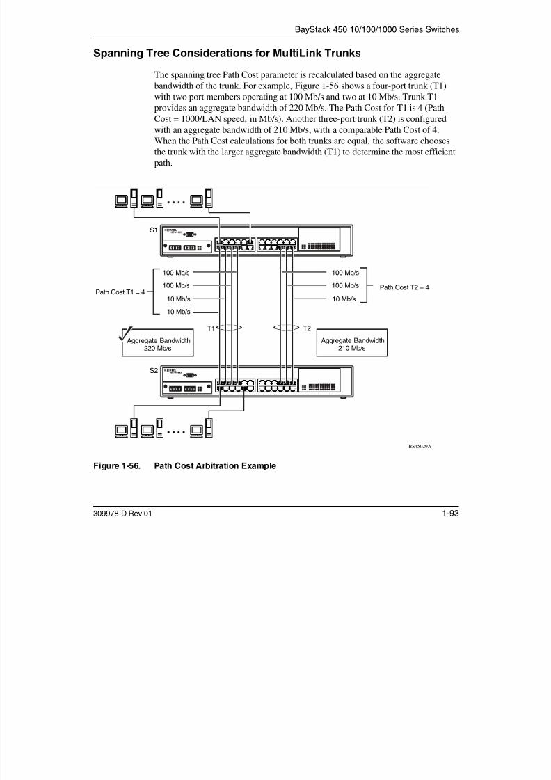
7/23/2019 Baystack 450
http://slidepdf.com/reader/full/baystack-450 125/399
309978-D Rev 01 1-93
Figure 1-56. Path Cost Arbitration Example
BS45029A
T1 T2
100 Mb/s
100 Mb/s
10 Mb/s
100 Mb/s
100 Mb/s
10 Mb/s
10 Mb/s
Path Cost T1 = 4
S1
S2
Path Cost T2 = 4
Aggregate Bandwidth220 Mb/s
Aggregate Bandwidth
210 Mb/s
Using the BayStack 450 10/100/1000 Series Switch
The switch can also detect trunk member ports that are physically misconfigured.For example, in Figure 1-57, trunk member ports 2, 4, and 6 of switch S1 areconfigured correctly to trunk member ports 7, 9, and 11 of switch S2. TheSpanning Tree Port Configuration screen for each switch shows the port state fieldfor each port in the Forwarding state.

7/23/2019 Baystack 450
http://slidepdf.com/reader/full/baystack-450 126/399
1-94 309978-D Rev 01
Figure 1-57. Example 1: Correctly Configured Trunk
T1
S1 Port Configuration screen
BS45030AS2 Port Configuration screen
S1
S2
BayStack 450 10/100/1000 Series Switches
If switch S2’s trunk member port 11 is physically disconnected and thenreconnected to port 13, the Spanning Tree Port Configuration screen for switch S1changes to show port 6 in the Blocking state (Figure 1-58).
[Blocking]

7/23/2019 Baystack 450
http://slidepdf.com/reader/full/baystack-450 127/399
309978-D Rev 01 1-95
Figure 1-58. Example 2: Detecting a Misconfigured Port
S1
S2
T1
S1 Port Configuration screen
BS45031A
S2 Port Configuration screen
Using the BayStack 450 10/100/1000 Series Switch
Additional Tips About the MultiLink Trunking Feature
When you create a MultiLink Trunk, the individual trunk members (the specificports that make up the trunk) logically connect and react as a single entity. Forexample, if you change spanning tree parameters for any trunk member, the
spanning tree parameters for all trunk members change.
All configured trunks are indicated in the Spanning Tree Configuration screen.The screen’s Trunk field lists the active trunks, adjacent to the port numbers thatcorrespond to the specific trunk member for that trunk.
When a trunk is active you can disable spanning tree participation using the Trunk
7/23/2019 Baystack 450
http://slidepdf.com/reader/full/baystack-450 128/399
1-96 309978-D Rev 01
Configuration screen or using the Spanning Tree Configuration screen.
When a trunk is not active, the spanning tree participation setting in the TrunkConfiguration screen does not take effect until you set the Trunk Status field toEnabled.
The trunk is also viewed by management stations as a single spanning tree port.The spanning tree port is represented by the trunk member with the lowest port
number. For example, if ports 13, 14, 15, and 16 are trunk members of trunk T1,the management station views trunk T1 as spanning tree port 13.
For more information about using the MultiLink Trunking feature, see “MultiLinkTrunk Configuration” on page 3-64.
Also see Appendix E, “Quick Steps to Features,” for configuration flowcharts thatcan help you use this feature.
BayStack 450 10/100/1000 Series Switches
Port Mirroring (Conversation Steering)
The port mirroring feature (sometimes referred to as conversation steering) allowsyou to designate a single switch port as a traffic monitor for up to two specifiedports or two media access control (MAC) addresses.
You can designate one of your switch ports to monitor traffic on any two specifiedswitch ports (port-based) or to monitor traffic to or from any two specifiedaddresses that the switch has learned (address-based).
Note: A probe device, such as the Nortel Networks StackProbe* or equivalent,must be connected to the designated monitor port to use this feature (contact

7/23/2019 Baystack 450
http://slidepdf.com/reader/full/baystack-450 129/399
309978-D Rev 01 1-97
The following sections provide sample configurations for both monitoring modesavailable with the Port Mirroring feature:
• Port-based mirroring
• Address-based mirroring
A sample Port Mirroring Configuration screen accompanies each networkconfiguration example. Note that the displayed screens do not show all of thescreen prompts that precede some actions.
For example, when you configure a switch for port mirroring or when you modifyan existing port mirroring configuration, the new configuration does not takeeffect until you respond [Yes] to the following screen prompt:
must be connected to the designated monitor port to use this feature (contact
your Nortel Networks sales agent for details about the StackProbe).
Is your port mirroring configuration complete? [ Yes ]
Using the BayStack 450 10/100/1000 Series Switch
Port-Based Mirroring Configuration
Figure 1-59 shows an example of a port-based mirroring configuration where port23 is designated as the monitor port for ports 24 and 25 of switch S1. Althoughthis example shows ports 24 and 25 monitored by the monitor port (port 23), any
of the trunk members of T1 and T2 can also be monitored.
Fig re 1 60 sho s the Port Mirroring Config ration screen set p for this e ample
Note: Trunks cannot be monitored and trunk members cannot be configuredas monitor ports (see “MultiLink Trunking Configuration Rules” onpage 1-90).

7/23/2019 Baystack 450
http://slidepdf.com/reader/full/baystack-450 130/399
1-98 309978-D Rev 01
Figure 1-60 shows the Port Mirroring Configuration screen setup for this example.
Figure 1-59. Port-Based Mirroring Configuration Example
BS45032A
StackProbe
S1
S2
S3
T 1
T2
FF Port Y
(port 24)
Monitor port(port 23)
Port X(port 25)
BayStack 450 10/100/1000 Series Switches
In the configuration example shown in Figure 1-59, the designated monitor port(port 23) can be set to monitor traffic in any of the following modes:
• Monitor all traffic port X receives.
• Monitor all traffic port X transmits.
• Monitor all traffic port X receives and transmits.
• Monitor all traffic port X receives or port Y transmits.
• Monitor all traffic port X receives (destined to port Y) and then port Ytransmits.
• Monitor all traffic port X receives/transmits and port Y

7/23/2019 Baystack 450
http://slidepdf.com/reader/full/baystack-450 131/399
309978-D Rev 01 1-99
receives/transmits (conversations between port X and port Y).As shown in the Port Mirroring Configuration screen example (Figure 1-60), port23 is designated as the Monitor Port for ports 24 and 25 in switch S1.
The Monitoring Mode field [ - > Port X or Port Y - > ] indicates that all trafficreceived by port X or all traffic transmitted by port Y is currently being monitoredby the StackProbe attached to Monitor Port 23.
The screen data displayed at the bottom of the screen shows the currently active
port mirroring configuration.
Note: The Unit value (in the Unit/Port field) cannot be configured when theswitch is operating standalone. For detailed information about the MultiLinkTrunk Configuration screen fields, see “MultiLink Trunk Configuration” onpage 3-64.
Using the BayStack 450 10/100/1000 Series Switch
Port Mirroring Configuration
Monitoring Mode: [ -> Port X or Port Y -> ]
Monitor Unit/Port: [ /23 ]Unit/Port X: [ /25 ]Unit/Port Y: [ /24 ]
Address A: [ 00-00-00-00-00-00 ]Address B: [ 00-00-00-00-00-00 ]

7/23/2019 Baystack 450
http://slidepdf.com/reader/full/baystack-450 132/399
1-100 309978-D Rev 01
Figure 1-60. Port Mirroring Port-Based Screen Example
Address-Based Mirroring Configuration
Figure 1-61 shows an example of an address-based mirroring configuration whereport 23, the designated monitor port for switch S1, is monitoring traffic occurring
between address A and address B.
Port mirroring configuration has taken effect.
Currently Active Port Mirroring Configuration---------------------------------------------
Monitoring Mode: -> Port X or Port Y -> Monitor Port: 23Port X: 25 Port Y: 24
Use space bar to display choices, press <Return> or <Enter> to select choice.Press Ctrl-R to return to previous menu. Press Ctrl-C to return to Main Menu.
BayStack 450 10/100/1000 Series Switches
S1
S2
StackProbe
T1
FF
Address A
Monitor port(port 23)

7/23/2019 Baystack 450
http://slidepdf.com/reader/full/baystack-450 133/399
309978-D Rev 01 1-101
Figure 1-61. Address-Based Mirroring Configuration Example
In this configuration, the designated monitor port (port 23) can be set to monitortraffic in any of the following modes:
• Monitor all traffic address A transmits to any address.
• Monitor all traffic address A receives from any address.
• Monitor all traffic address A receives or transmits.
• Monitor all traffic address A transmits to address B.
• Monitor all traffic between address A and address B (conversation betweenthe two stations).
Figure 1-62 shows the Port Mirroring Configuration screen setup for this example.
S2
S3
BS45033A
T2
Address B
Using the BayStack 450 10/100/1000 Series Switch
In this example, port 23 becomes the designated Monitor Port for switch S1 whenyou press [Enter] in response to the [Yes] screen prompt.
The Monitoring Mode field [ Address A - > Address B ] indicates that alltraffic transmitted by address A to address B will be monitored by the StackProbeattached to Monitor Port 23.
Note: The screen data displayed at the bottom of the screen changes to show
the new currently active port mirroring configuration after you press [Enter].

7/23/2019 Baystack 450
http://slidepdf.com/reader/full/baystack-450 134/399
1-102 309978-D Rev 01
Figure 1-62. Port Mirroring Address-Based Screen Example
Note: When you enter MAC addresses in this screen, they are also displayedin the MAC Address Table screen (see “MAC Address Table” on page 3-22).
Port Mirroring Configuration
Monitoring Mode: [ Address A -> Address B ]Monitor Unit/Port: [ /23 ]
Unit/Port X: [ / ]Unit/Port Y: [ / ]
Address A: [ 00-44-55-44-55-22 ]Address B: [ 00-33-44-33-22-44 ]
Is your port mirroring configuration complete? [ Yes ]
Currently Active Port Mirroring Configuration---------------------------------------------
Monitoring Mode: -> Port X or Port Y -> Monitor Port: 23Port X: 25 Port Y: 24
Use space bar to display choices, press <Return> or <Enter> to select choice.Press Ctrl-R to return to previous menu. Press Ctrl-C to return to Main Menu.
BayStack 450 10/100/1000 Series Switches
Port Mirroring Configuration Rules
The following configuration rules apply to any port mirroring configuration:
• Any port that is currently configured for EAPOL-based security cannot beconfigured for port mirroring.
• You cannot configure a monitor port as a trunk member or IGMP member.
• A monitor port cannot be used for normal switch functions.
• When you configure a port as a monitor port, the port is automaticallydisabled from participating in the spanning tree. When you reconfigure theport as a standard switch port (no longer a monitor port), the port is enabled

7/23/2019 Baystack 450
http://slidepdf.com/reader/full/baystack-450 135/399
309978-D Rev 01 1-103
for spanning tree participation.• When you create a port-based port mirroring configuration, be sure that the
monitor port and both of the mirrored ports, port X and port Y, have the sameconfiguration. Use the VLAN Configuration screen to configure the VLAN(see “VLAN Configuration” on page 3-46).
• VLAN configuration settings for any ports configured for port-basedmirroring cannot be changed. Use the Port Mirroring Configuration screen to
disable port mirroring (or reconfigure the port mirroring ports), and thenchange the VLAN configuration settings.
• For port-based traffic monitoring, use one of the following modes formonitoring broadcast, IP multicast, or unknown DA frames:
-- Monitor all traffic received by port X.
-- Monitor all traffic transmitted by port X.
-- Monitor all traffic received and transmitted by port X.
For more information about using the Port Mirroring feature, see “Port MirroringConfiguration” on page 3-71.
Also see Appendix E, “Quick Steps to Features,” for configuration flowcharts thatcan help you use this feature.

7/23/2019 Baystack 450
http://slidepdf.com/reader/full/baystack-450 136/399
Chapter 2
Installing the BayStack 450 Switch
This chapter covers the following topics:

7/23/2019 Baystack 450
http://slidepdf.com/reader/full/baystack-450 137/399
309978-D Rev 01 2-1
• “Installation Requirements” (page 2-1)
• “Installation Procedure” (page 2-3)
• “Connecting Power” (page 2-12)
• “Verifying the Installation” (page 2-14)
• “Initial Setup” (page 2-17)
Refer to Chapter 3, “Using the Console Interface,” to further configure yourBayStack 450 switch.
Installation Requirements
Before installing the BayStack 450 switch, verify that the package contains the
following items in addition to this guide (see Figure 2-1).
Install the BayStack 450 switch in a ventilated area that is dust free and away from
heat vents, warm air exhaust from other equipment, and direct sunlight. Avoidproximity to large electric motors or other electromagnetic equipment. Whenchoosing a location, observe the environmental guidelines listed in Appendix A,“Technical Specifications.” You will need a Phillips screwdriver for theinstallation.
Note: Be sure that the supplied AC power cord matches the requirements foryour region; see “AC Power Receptacle” on page 1-10.
Using the BayStack 450 10/100/1000 Series Switch

7/23/2019 Baystack 450
http://slidepdf.com/reader/full/baystack-450 138/399
2-2 309978-D Rev 01
Figure 2-1. Package Contents
The number of boxes and their contents depends on the options you ordered. Openany accessories box and verify that the contents agree with your bill of materials.If any items are missing or damaged, contact the sales agent or the customerservice representative from whom you purchased the BayStack 450 switch.
Note: Your shipping box may be configured differently than shown in Figure 2-1; the contents will be the same.
Using the BayStack 45010/100/1000 Series Switch
BayStack 450 switch
Mountingbrackets
and screws
BS45034B
Rubberfootpads
AC power cord
Owner registration card
Customer registration card
Release notes
Documentation:Installation hardware:
Installing the BayStack 450 Switch
Installation Procedure
This section provides the requirements and instructions for installing theBayStack 450 switch on a flat surface or in a standard 19-inch utility rack. If youinstall the switch in a rack, ground the rack to the same grounding electrode used
by the power service in the area. The ground path must be permanent and must notexceed 1 ohm of resistance from the rack to the grounding electrode.
Note: An optional wall mount kit is available for the BayStack 450 switch(Order Number Al2018003). See your Nortel Networks sales representativefor ordering information. Installation instructions are provided with the wallmount kit.
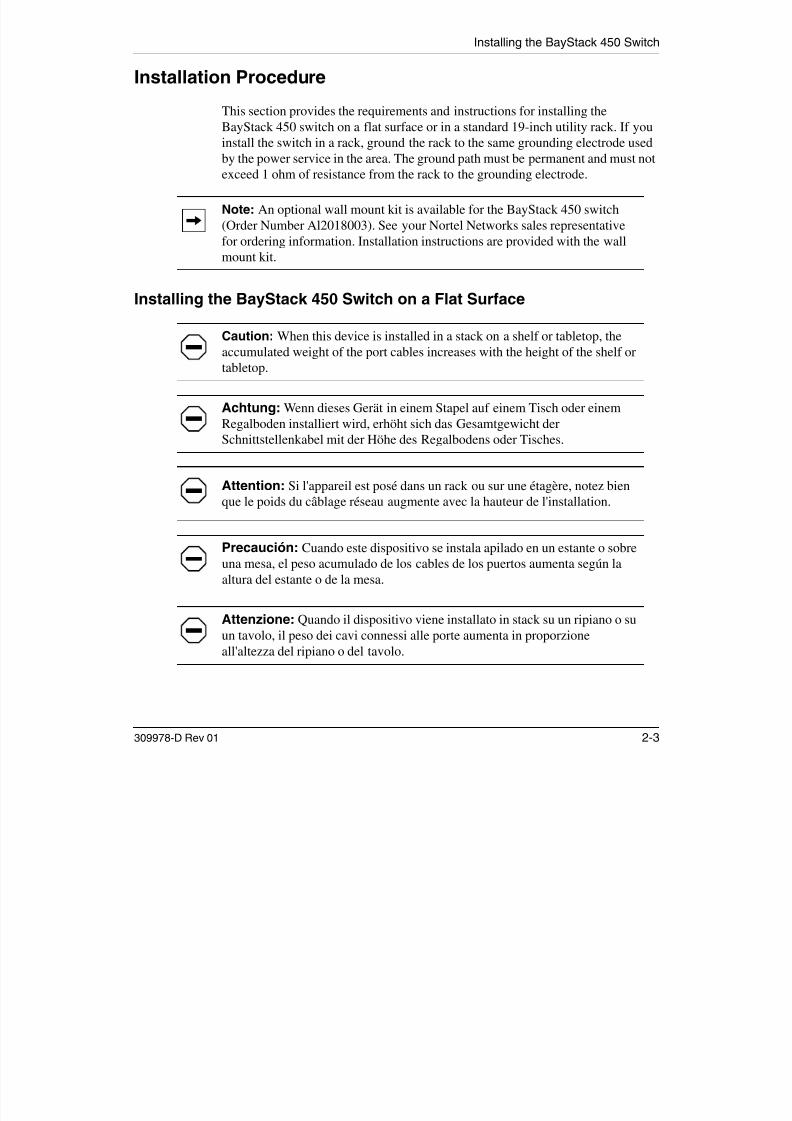
7/23/2019 Baystack 450
http://slidepdf.com/reader/full/baystack-450 139/399
309978-D Rev 01 2-3
Installing the BayStack 450 Switch on a Flat Surface
Caution: When this device is installed in a stack on a shelf or tabletop, theaccumulated weight of the port cables increases with the height of the shelf ortabletop.
Achtung: Wenn dieses Gerät in einem Stapel auf einem Tisch oder einemRegalboden installiert wird, erhöht sich das Gesamtgewicht derSchnittstellenkabel mit der Höhe des Regalbodens oder Tisches.
Attention: Si l'appareil est posé dans un rack ou sur une étagère, notez bien
que le poids du câblage réseau augmente avec la hauteur de l'installation.
Precaución: Cuando este dispositivo se instala apilado en un estante o sobreuna mesa, el peso acumulado de los cables de los puertos aumenta según laaltura del estante o de la mesa.
Attenzione: Quando il dispositivo viene installato in stack su un ripiano o suun tavolo, il peso dei cavi connessi alle porte aumenta in proporzioneall'altezza del ripiano o del tavolo.
Using the BayStack 450 10/100/1000 Series Switch
The BayStack 450 switch can be mounted onto any appropriate flat, level surfacethat can safely support the weight of the switch and its attached cables, as long asthere is adequate space around the unit for ventilation and access to cableconnectors.
To install the switch on a tabletop, shelf, or any other flat surface, follow thesesteps:
1 Set the switch on the flat surface and check for proper ventilation

7/23/2019 Baystack 450
http://slidepdf.com/reader/full/baystack-450 140/399
2-4 309978-D Rev 01
1. Set the switch on the flat surface and check for proper ventilation.
Allow at least 2 inches (5.1 cm) on each side for proper ventilation and5 inches (12.7 cm) at the back for power cord clearance.
2. Attach rubber feet to each marked location on the bottom of the chassis.
The rubber feet are optional but recommended to keep the unit from slipping.
3. Attach all devices to the ports.
See “Attaching Devices to the BayStack 450 Switch” on page 2-7.
Installing the BayStack 450 Switch in a Rack
Caution: When mounting this device in a rack, do not stack units directly ontop of one another in the rack. Each unit must be secured to the rack with
appropriate mounting brackets. Mounting brackets are not designed to supportmultiple units.
Achtung: Wenn Sie dieses Gerät in einem Gerätegestell installieren, stellenSie die Geräte nicht direkt aufeinander. Jedes Gerät muß mit entsprechendenHalterungen im Gestell befestigt werden. Die Halterungen sind nicht dafürkonzipiert, mehrere Geräte zu tragen.
Attention: Si cet appareil doit être encastré dans un rack, ne jamais empilerdirectement plusieurs unités les unes sur les autres. Chaque unité doit êtrecorrectement fixée avec les membrures appropriées. Les membrures ne sontpas conçues pour supporter le poids d'unités multiples.
Installing the BayStack 450 Switch
Precaución: Al montar este dispositivo apilado con otros dispositivos, noapile las unidades directamente unas sobre otras. Cada unidad se debe fijar a laestructura mediante los soportes de montaje adecuados. Los soportes demontaje no están diseñados para soportar varias unidades.
Attenzione: Se il dispositivo viene installato su una cremagliera, nonimpilarlo su un altro dispositivo montato sulla cremagliera. Ciascuna unitàdeve essere fissata alla cremagliera con le apposite staffe di montaggio. Talistaffe non possono essere utilizzate per fissare più unità.

7/23/2019 Baystack 450
http://slidepdf.com/reader/full/baystack-450 141/399
309978-D Rev 01 2-5
The BayStack 450 switch occupies a 1.6-unit (1.6u) rack space and can be
installed in most standard 19-inch racks. The rack must be grounded to the samegrounding electrode used by the power service in the area. The ground path mustbe permanent and must not exceed 1 ohm of resistance from the rack to thegrounding electrode.
To install the BayStack 450 switch in a rack, follow these steps:
1. Determine how far you want the switch to protrude in front of the rack.
Figure 2-2. Positioning the Chassis in the Rack
BS45035A
1 = Flush with rack
2 = Extended from rack
1 2
Using the BayStack 450 10/100/1000 Series Switch
You can install the switch flush to the rack or extended from the rack,depending on the orientation of the mounting brackets.
2. Using a Phillips screwdriver, attach a mounting bracket to each side of
the switch using the supplied screws (Figure 2-3).
1

7/23/2019 Baystack 450
http://slidepdf.com/reader/full/baystack-450 142/399
2-6 309978-D Rev 01
Figure 2-3. Attaching Mounting Brackets
3. Position the switch in the rack and align the holes in the mounting
bracket with the holes in the rack (see Figure 2-4).
Figure 2-4. Installing the BayStack 450 Switch in an Equipment Rack
BS45036A
1 = Flush with rack
2 = Extended from rack
2
BS45037A
Installing the BayStack 450 Switch
4. Insert two screws, appropriate for your 19-inch rack, into each of the
mounting brackets and tighten.
5. After the switch is secured in the rack, see the next section, “Attaching
Devices to the BayStack 450 Switch.”
Attaching Devices to the BayStack 450 Switch
This section describes how to attach devices to the BayStack 450 switch ports andhow to connect a console terminal to the switch Console/Comm port. You can usethe console terminal to observe the power-on self-test results and set up theswitch, if required, as described later in this chapter.
The BayStack 450 switch has an Uplink/Expansion slot that allows you to attach

7/23/2019 Baystack 450
http://slidepdf.com/reader/full/baystack-450 143/399
309978-D Rev 01 2-7
The BayStack 450 switch has an Uplink/Expansion slot that allows you to attachoptional media dependent adapters (MDAs). The MDAs support a range of mediatypes (see Appendix C, “Media Dependent Adapters,” for more information aboutMDA types available from Nortel Networks). Refer to the documentation thatcame with your specific MDA for information about its cabling and LEDindications.
BayStack 450 switches that are configured with BayStack 450 software versionV1.1.0 or later provide Fail-Safe stackability when you install the optionalBayStack 400-ST1 Cascade Module to your switches. Installation instructions areprovided with the Cascade Module. If you need to upgrade your BayStack 450switches, refer to the upgrade instructions provided in Installing the BayStack
400-ST1 Cascade Module. You must upgrade the switch before installing theBayStack 400-ST1 Cascade Module.
Depending on your network configuration requirements, connect the port cables,the console port, and any optional MDA port cables as described in the followingsections. After attaching the devices to the BayStack 450 switch, see “ConnectingPower” on page 2-12 to connect the AC power cord and power up the switch.
You can connect the BayStack 450 switch to any equipment that conforms to theIEEE 802.3 standard, such as the following devices:
• Ethernet networking devices• Individual workstations or servers
• Other switches, bridges, or hubs
Using the BayStack 450 10/100/1000 Series Switch
Connecting the 10BASE-T/100BASE-TX Ports
Connect devices to the 10BASE-T/100BASE-TX (10/100) ports as shown inFigure 2-5.
The 10/100 switch ports are configured with RJ-45 connectors that are wired asMDI-X ports. As in conventional Ethernet repeater hubs, these ports connect viastraight-through cables to the network interface card (NIC) in a node or server.When connecting to an Ethernet hub or to another switch, you must use acrossover cable. See Appendix F, “Connectors and Pin Assignments,” for moreinformation.
By default, all BayStack 450 switch 10/100 switch ports are set with
autonegotiation enabled. This feature allows any port to match the best serviceid d b th t d t ti t 100 Mb/ i f ll d l d

7/23/2019 Baystack 450
http://slidepdf.com/reader/full/baystack-450 144/399
2-8 309978-D Rev 01
autonegotiation enabled. This feature allows any port to match the best serviceprovided by the connected station, up to 100 Mb/s in full-duplex mode.
To connect the RJ-45 port cables, insert the cable plug into the appropriate portconnector until the release tab snaps into the locked position (Figure 2-5).
Figure 2-5. 10/100 Mb/s Port Connections
Note: The 10BASE-T/100BASE-TX ports must use Category 5 UTP cable toaccommodate the 100BASE-TX functionality.
Uplink/Expansion Module 2826 2725
Comm Port
17 1913 15 21
18 2014 16 22 24
23
Status Dwn
P wr U p
Cas
RPSUBaseActivity
Activity
10/100
10/100
5 71 3 9
6 82 4 10 12
11
BS45073A
Comm Port
Activity
100
10
F Dx
400-4TX MDA
400-4TX MDA
RJ-45 connector

7/23/2019 Baystack 450
http://slidepdf.com/reader/full/baystack-450 145/399
Using the BayStack 450 10/100/1000 Series Switch
Console/Comm Port
The serial console interface is an RS-232 port that enables a connection to a PC orterminal for monitoring and configuring a standalone switch or a stackconfiguration. You can also connect this port to an external modem to enable
remote dial-in management of the switch. The port is a male DB-9 connector,implemented as a data communication equipment (DCE) connection.
To use the Console/Comm port, you need the following equipment:
• A VT100 or ANSI-compatible terminal, or a PC with a serial port and theability to emulate a VT100 terminal.
Configure the terminal settings as follows:
-- 9600 baud

7/23/2019 Baystack 450
http://slidepdf.com/reader/full/baystack-450 146/399
2-10 309978-D Rev 01
-- No parity
-- 8 bits
-- 1 stop bit
-- Flow control set to Xon/Xoff
-- Window Terminal Emulator option set to NO
-- Terminal Preferences: Function, Arrow, and Control keys active
-- Buffer size set to 24
• A UL-listed straight-through RS-232 cable with a female DB-9 connector forthe console port on the switch.
The other end of the cable must have a connector appropriate to the serial porton your computer or terminal. (Most terminals or computers use a male DB-25connector.)
Any cable connected to the console port must be shielded to comply withemissions regulations and requirements.
See “DB-9 (RS-232-D) Console/Comm Port Connector” on page F-5 for a
description of the pin assignments.
Installing the BayStack 450 Switch
Connecting a Terminal to the Console/Comm Port
To connect a terminal to the console port, follow these steps:
1. Set the terminal protocol as described in “Console/Comm Port” on
page 2-10.
2. Connect the terminal (or a computer in terminal-emulation mode) to the
console port using the RS-232 cable.
a. Connect the female connector of the RS-232 cable directly to the
Console/Comm Port on the switch, and then tighten the captive
retaining screws (see Figure 2-7).
b. Connect the other end of the cable to a terminal or the serial
connector of a personal computer running communications software.

7/23/2019 Baystack 450
http://slidepdf.com/reader/full/baystack-450 147/399
309978-D Rev 01 2-11
Figure 2-7. Connecting to the Console/Comm Port
3. See the next section, “Connecting Power,” to connect the AC power cord
and power up the BayStack 450 switch.
Comm Port
172FC
Using the BayStack 450 10/100/1000 Series Switch
Connecting Power
The BayStack 450 switch does not have a power on/off switch. When you connectthe AC power cord to a suitable AC power outlet, the switch powers upimmediately.
Warning: Removal of the power cord is the only way to turn off power to thisdevice. The power cord must always be connected in a location that can beaccessed quickly and safely in case of an emergency.
Vorsicht: Die Stromzufuhr zu diesem Gerät kann nur durch Ziehen desNetzstromkabels unterbrochen werden. Die Netzsteckdose, an die dasNetzstromkabel angeschlossen ist, muß sich stets an einem Ort befinden, der

7/23/2019 Baystack 450
http://slidepdf.com/reader/full/baystack-450 148/399
2-12 309978-D Rev 01
bei einem Notfall schnell und einfach zugänglich ist.
Avertissement: Le débranchement du cordon d'alimentation constitue leseul moyen de mettre cet appareil hors tension. Le cordon d'alimentation doitdonc toujours être branché dans une prise accessible pour faciliter la mise hors
tension en cas d'urgence.
Advertencia: La única forma de desconectar la alimentación de estedispositivo es desenchufar el cable de alimentación. El cable de alimentaciónsiempre debe estar conectado en una ubicación que permita acceder al cable deforma rápida y segura en caso de emergencia.
Avvertenza: Estrarre il cavo di alimentazione è l'unico sistema per spegnereil dispositivo. Il cavo di alimentazione deve essere sempre collegato in unaposizione che permetta l'accesso facile e sicuro in caso di emergenza.
Installing the BayStack 450 Switch
To connect the AC power cord, follow these steps:
1. Plug one end of the AC power cord into the AC power receptacle on the
switch back panel (Figure 2-8).
Figure 2-8. BayStack 450 Switch AC Power Receptacle
Cascade Module
Redundant Power
100-240V47-63Hz~
BS45039A

7/23/2019 Baystack 450
http://slidepdf.com/reader/full/baystack-450 149/399
309978-D Rev 01 2-13
g y p
2. Plug the other end of the AC power cord into the grounded AC power
outlet (Figure 2-9).
Figure 2-9. Grounded AC Power Outlet
3. See the next section, “Verifying the Installation.”
612FA
Using the BayStack 450 10/100/1000 Series Switch
Verifying the Installation
When power is applied to the switch, power-on self-tests run. You can verifyproper operation of the BayStack 450 switch by observing the front-panel LEDsor by viewing the self-test results as displayed in the BayStack 450 switch
Self-Test screen.
Verifying the Installation Using the LEDs
To verify the installation using the LEDs, check that the switch power-upsequence is as described in Table 2-1:
Table 2-1. Power-Up Sequence

7/23/2019 Baystack 450
http://slidepdf.com/reader/full/baystack-450 150/399
2-14 309978-D Rev 01
Figure 2-10. Observing LEDs to Verify Proper Operation
Stage Description LED indication
1 Immediately after AC power is
applied to the switch, DC power
is available to the switch’s
internal circuitry.
The Power LED turns on within 5 seconds (Figure 2-10). If the
Power LED does not turn on, verify that power is available at the
AC power outlet and that the power cable is fastened securely at
both ends. If the Power LED remains off, contact the sales agent
or the customer service representative from whom you
purchased the switch.
2 The switch initiates a self-test. As the self-test initiates subroutines, the port status LEDs flash
various patterns. When the switch passes the self-test (within 10
seconds), the Status LED turns on (Figure 2-10).
If a nonfatal error occurs during self-test, the Status LED blinks.
If the switch fails the self-test, the Status LED remains off.
Contact the sales agent or the customer service representative
from whom you purchased the switch.
Power LED
Status LED
BS45040A
450-24T SwitchBayStack
Status Dwn
Pwr Up
1 53Cas
RPSUBaseActivity
Activity
2119 2310/100
10/100
1713 15117 9
2 64 2220 241814 16128 10
Installing the BayStack 450 Switch
Verifying the Installation Using the Self-Test Screen
If a monitor is connected to the switch (see “Console/Comm Port” on page 2-10),you can observe the BayStack 450 switch Self-Test screen (Figure 2-11 shows anexample of a standalone switch Self-Test screen).
The results of the self-test are displayed briefly (5 or 10 seconds) on the Self-Testscreen, which is followed by the Nortel Networks Logo screen (Figure 2-12).
Note: The Self-Test screen remains displayed only if the self-test detects afatal error.

7/23/2019 Baystack 450
http://slidepdf.com/reader/full/baystack-450 151/399
309978-D Rev 01 2-15
Figure 2-11. BayStack 450 Switch Self-Test Screen
Note: The Self-Test screen for a switch that is participating in a stackconfiguration includes an additional test: Cascade SRAM test.
BayStack 450-xxx Self-Test
CPU RAM test ... PassASIC addressing test ... PassASIC buffer RAM test ... PassASIC buffer stack init test ... PassPort internal loopback test ... PassCascade SRAM test ... PassFan test ... Pass
Self-test complete.
Using the BayStack 450 10/100/1000 Series Switch
******************************************************** Nortel Networks ** Copyright (c) 1996,2001 ** All Rights Reserved ** BayStack 450-24T ** Versions: HW:Revx FW:Vx.xx SW:vx.x.x.x ISVN:x ********************************************************

7/23/2019 Baystack 450
http://slidepdf.com/reader/full/baystack-450 152/399
2-16 309978-D Rev 01
Figure 2-12. Nortel Networks Logo Screen
Upon successful completion of the power-up self-tests, the switch is ready fornormal operation.
To access the BayStack 450 Main Menu, press [Ctrl]-Y.
Note: The Nortel Networks logo screen for your switch will display thecorrect model number and the current hardware, firmware, software, and ISVNversions.
Enter Ctrl-Y to begin.
Installing the BayStack 450 Switch
Initial Setup
The BayStack 450 switch is designed for “plug-and-play” operation; in most casesthe switch can be installed and made operational using the system default settings(see Appendix G, “Default Settings,” for a list of default settings for the BayStack
450 switch).
However, for the switch management function to become fully operational, certainparameters must be configured. A minimal configuration is required when youplan on remote management or TFTP operations.
If you are configuring your BayStack 450 switches in a stack configuration, youmust supply additional parameters to properly set up the stack.
This section includes the following information:
7/23/2019 Baystack 450
http://slidepdf.com/reader/full/baystack-450 153/399
309978-D Rev 01 2-17
• Instructions for the initial (standalone) switch setup
• Instructions for the initial stack setup
After setting up your switch or stack configuration as described in the followingsections, see Chapter 3, “Using the Console Interface,” for detailed descriptions of the menus and screens you can use to customize your configuration.
Standalone Switch Setup
For the initial setup of a standalone switch, you need to enter the IP address of theswitch, the subnet mask, and the gateway address (see Chapter 3, “Using theConsole Interface,” for more information about configuring your BayStack 450switch).
To set the IP address, subnet mask, and gateway address for the switch, followthese steps:
1. Apply power to the switch.
2. After the Nortel Networks logo screen appears, press [Ctrl]-Y.
The Main Menu is displayed (Figure 2-13). The Main Menu hierarchy isdescribed in Chapter 3, “Using the Console Interface.”
Using the BayStack 450 10/100/1000 Series Switch
BayStack 450-24T Main Menu
IP Configuration/Setup...
SNMP Configuration...System Characteristics...Switch Configuration...Console/Comm Port Configuration...Display Hardware Units...Spanning Tree Configuration...TELNET/SNMP Mgr List Configuration...Software Download...Configuration File...Display Event LogSave Current SettingsResetReset to Default SettingsLogout

7/23/2019 Baystack 450
http://slidepdf.com/reader/full/baystack-450 154/399
2-18 309978-D Rev 01
Figure 2-13. Main Menu for Standalone Switch
3. Select IP Configuration/Setup (or press i) from the Main Menu.
This selection displays the IP Configuration/Setup screen (Figure 2-14).
Note: The default management VLAN (IP interface) for the BayStack 450switch is VLAN 1. However, you can specify which VLAN you want to be themanagement VLAN (see “VLAN Configuration” on page 3-46).
Logout
Use arrow keys to highlight option, press <Return> or <Enter> to select option.
Installing the BayStack 450 Switch
IP Configuration/Setup
BootP Request Mode: [ BootP Disabled ]
Configurable In Use Last BootP------------------- --------------- ---------------
In-Band Stack IP Address: [ 0.0.0.0 ] 0.0.0.0In-Band Switch IP Address: [ 0.0.0.0 ] 0.0.0.0In-Band Subnet Mask: [ 0.0.0.0 ] 0.0.0.0 0.0.0.0Default Gateway: [ 0.0.0.0 ] 0.0.0.0 0.0.0.0
IP Address to Ping: [ 0.0.0.0 ]
Start Ping: [ No ]

7/23/2019 Baystack 450
http://slidepdf.com/reader/full/baystack-450 155/399
309978-D Rev 01 2-19
Figure 2-14. IP Configuration/Setup Screen (Standalone Switch)
4. Enter the IP address of the switch in the In-Band IP Address field, and
then press [Enter].
5. Enter the IP subnet mask address in the In-Band Subnet Mask field, and
then press [Enter].
6. Enter the default gateway address in the Default Gateway field, and then
press [Enter].
See Chapter 3, “Using the Console Interface,” for detailed descriptions of themenus and screens you can use to customize your configuration.
Note: When you enter the IP address in the In-Band Stack/Switch IP
Address field, and the In-Band Subnet Mask field is not present, thesoftware provides an in-use default value for the In-Band Subnet Maskfield, based on the class of the entered IP address.
Use space bar to display choices, press <Return> or <Enter> to select choice.Press Ctrl-R to return to previous menu. Press Ctrl-C to return to Main Menu.
Using the BayStack 450 10/100/1000 Series Switch
Stack Setup
For the initial setup of a stack configuration, you need to enter the stack IPaddress, the subnet mask, and the gateway address (see Chapter 3, “Using theConsole Interface,” for more information about configuring your BayStack 450
switch).To set the stack IP address, subnet mask, and gateway address for the switch,follow these steps:
1. Connect a console/terminal to one of the switches in the stack.
Note: Unless otherwise specified, the terms “switch” and “unit” are usedinterchangeably in this guide.

7/23/2019 Baystack 450
http://slidepdf.com/reader/full/baystack-450 156/399
2-20 309978-D Rev 01
You can connect a console/terminal to any unit in the stack or to more thanone stack unit (see “Console/Comm Port” on page 2-10).
2. Power up the stack configuration.
Observe the console display screen.
3. After the Nortel Networks logo screen appears, press [Ctrl]-Y.
The following occurs:
• The console screen temporarily displays the (standalone) Main Menuscreen (see Figure 2-15).
This is the same Main Menu screen that is displayed for a standalone
switch, without stacking features.• Within 20 seconds after displaying the standalone Main Menu screen, the
console screen refreshes to show the Main Menu screen for the stackconfiguration (Figure 2-16).
Although the Main Menu screen for the stack configuration looks similarto the standalone Main Menu screen, closer observation reveals that the
stack features are included (see bolded text in Figure 2-16 on page 2-21).
Installing the BayStack 450 Switch
BayStack 450-24T Main Menu
IP Configuration/Setup...
SNMP Configuration...System Characteristics...Switch Configuration...Console/Comm Port Configuration...Display Hardware Units...Spanning Tree Configuration...TELNET/SNMP Mgr List Configuration...Software Download...Configuration File...Display Event LogSave Current Settings
ResetReset to Default SettingsLogout
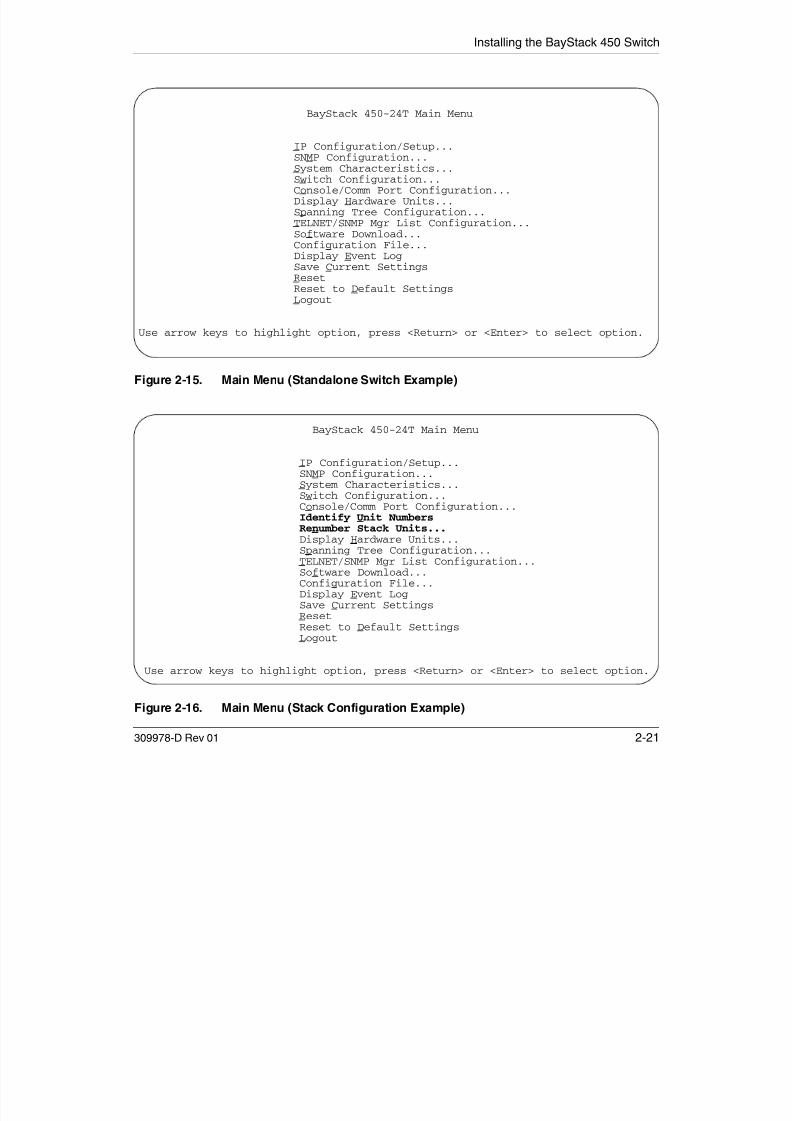
7/23/2019 Baystack 450
http://slidepdf.com/reader/full/baystack-450 157/399
309978-D Rev 01 2-21
Figure 2-15. Main Menu (Standalone Switch Example)
Figure 2-16. Main Menu (Stack Configuration Example)
Use arrow keys to highlight option, press <Return> or <Enter> to select option.
BayStack 450-24T Main Menu
IP Configuration/Setup...SNMP Configuration...System Characteristics...Switch Configuration...
Console/Comm Port Configuration... Identify Unit Numbers Renumber Stack Units...
Display Hardware Units...Spanning Tree Configuration...TELNET/SNMP Mgr List Configuration...Software Download...Configuration File...Display Event LogSave Current Settings
ResetReset to Default SettingsLogout
Use arrow keys to highlight option, press <Return> or <Enter> to select option.

7/23/2019 Baystack 450
http://slidepdf.com/reader/full/baystack-450 158/399
Installing the BayStack 450 Switch
6. Enter the IP subnet mask address in the In-Band Subnet Mask field, and
then press [Enter].
7. Enter the default gateway address in the Default Gateway field, and then
press [Enter].
See Chapter 3, “Using the Console Interface,” for detailed descriptions of themenus and screens you can use to customize your configuration.

7/23/2019 Baystack 450
http://slidepdf.com/reader/full/baystack-450 159/399
309978-D Rev 01 2-23

7/23/2019 Baystack 450
http://slidepdf.com/reader/full/baystack-450 160/399
Chapter 3
Using the Console Interface
This chapter describes how to configure and manage the BayStack 450 switchusing the menu-driven console interface (CI).
This chapter covers the following topics:• “Accessing the CI Menus and Screens” (page 3-2)
• “Main Menu” (page 3-5)
7/23/2019 Baystack 450
http://slidepdf.com/reader/full/baystack-450 161/399
309978-D Rev 01 3-1
• Main Menu (page 3-5)
• “IP Configuration/Setup” (page 3-9)
• “SNMP Configuration” (page 3-14)
• “System Characteristics” (page 3-16)
• “Switch Configuration” (page 3-19)
• “Console/Comm Port Configuration” (page 3-100)
• “Identify Unit Numbers” (page 3-107)
• “Renumber Stack Units” (page 3-107)
• “Display Hardware Units” (page 3-109)
• “Spanning Tree Configuration” (page 3-110)
• “TELNET/SNMP Manager List Configuration” (page 3-118)
• “Software Download” (page 3-121)
• “Configuration File” (page 3-125)
• “Display Event Log” (page 3-128)
• “Save Current Settings” (page 3-131)• “Reset” (page 3-131)
• “Reset to Default Settings” (page 3-133)
• “Logout” (page 3-136)
Using the BayStack 450 10/100/1000 Series Switch
Accessing the CI Menus and Screens
You can access the CI menus and screens locally through a console terminal,remotely through a dial-up modem connection, or in-band through a TELNETsession (see “Console/Comm Port” on page 2-10).
You can also manage the BayStack 450 switch using Nortel Networks Optivitynetwork management software or any generic SNMP-based management
software; however, for the switch management function to become fullyoperational, you must supply certain parameters such as the switch IP address orstack IP address, if configured (see “Initial Setup” on page 2-17).
Note: If your stack configuration includes one or more Business Policy Switch2000 switches, you must use the Business Policy Switch 2000 switch consoleinterface to configure or monitor your stack.

7/23/2019 Baystack 450
http://slidepdf.com/reader/full/baystack-450 162/399
3-2 309978-D Rev 01
For information about SNMP, see your network management documentation.
Using the CI Menus and Screens
The CI menus and screens provide options that allow you to configure andmanage the BayStack 450 switch.
Help prompts at the bottom of each menu and screen explain how to enter data inthe highlighted field and how to navigate the menus and screens. Some optionsallow you to toggle among several possible values; other options allow you to setor modify a parameter.
Note: If you have a properly configured BootP server in your network, it willdetect the IP address; you will not need to configure the IP address.
Using the Console Interface
Navigating the CI Menus and Screens
Use the following methods to navigate the CI menus and screens:
• To select a menu option:
a. Use the arrow keys to highlight the option name.
b. Press [Enter].
The option takes effect immediately after you press [Enter].
Alternatively, you can press the key corresponding to the underlined letter inthe option name. For example, to select the Switch Configuration option in themain menu, press the w key. Note that the text characters are not
case-sensitive.• To toggle between values in a form:
a. Use the spacebar to highlight the value.

7/23/2019 Baystack 450
http://slidepdf.com/reader/full/baystack-450 163/399
309978-D Rev 01 3-3
a. Use t e spaceba to g g t t e va ue.
b. Press [Enter].
• To clear a string field:
a. Position the cursor in the string field.b. Press [Ctrl]-K.
• To return to the previous menu, press [Ctrl]-R.
• To return to the main menu at any time, press [Ctrl]-C.
• Press [Backspace] to delete entered text.
• Accelerator keysYou can use accelerator keys to enter repetitive data into the fields of certainscreens. The accelerator keys can be used only on fields that require entering alist, which includes the MAC Address Security Port Lists screen and the MACAddress Security Table screen.
For more information about using the accelerator keys, see “Accelerator Keysfor Repetitive Tasks” on page 3-35.
Using the BayStack 450 10/100/1000 Series Switch
Map of CI Menus and Screens
Figure 3-1 shows a map of the CI screens. The remainder of this chapter describesthe CI screens and their fields, beginning with the main menu.
IP Configuration/Setup
SNMP Configuration
System Characteristics
Switch Configuration
Console/Comm Port Configuration
Identify Unit Numbers
Renumber Stack Units
Display Hardware UnitsSpanning Tree Configuration
TELNET/SNMP Mgr List Configuration
Software Download
Main MenuMAC Address Table
MAC Address-Based Security
EAPOL Security Configuration
VLAN Configuration
Port Configuration
High Speed Flow Control
Configuration
MultiLink Trunk Configuration
Port Mirroring Configuration
Rate Limiting Configuration
IGMP Configuration
Display Port Statistics
VLAN Configuration
VLAN Port Configuration
VLAN Display by Port
Traffic Class Configuration
MultiLink Trunk Configuration
MultiLink Trunk Utilization
1
1
MAC Address Security Configuration
MAC Address Security Port Configuration
MAC Address Security Port Lists
MAC Address Security Table
2

7/23/2019 Baystack 450
http://slidepdf.com/reader/full/baystack-450 164/399
3-4 309978-D Rev 01
Figure 3-1. Map of Console Interface Screens
The CI screens for your specific switch model will show the correct model namein the main menu title and the correct number of ports and port types in the PortConfiguration screen.
Note: The field values shown in the CI screens in this section are provided asexamples only.
Software Download
Configuration File
Display Event Log
Save Current Settings
Reset
Reset to Default SettingsLogout
Display Port Statistics
Clear All Port Statistics
ATM Configuration
Spanning Tree Port Configuration
Display Spanning Tree Switch Settings
BS45087B
IGMP Configuration
Display Multicast Group Membership
Only appears when the switch is participating in a stack configuration.
Only appears when a gigabit MDA is installed in one or more units in a stack configuration.
Only appears when an ATM MDA is installed in one or more units in a stack configuration.
1
2
3
3
Using the Console Interface
Main Menu
This section describes the options available from the CI main menu (Figure 3-2).The CI screens and submenus for these options are described in the followingsections.
Note: Some menu options shown in this main menu example and in otherscreen examples in this chapter may not appear on your screen, depending onthe switch options installed. However, the full menu options are shown in thescreen examples and described in the following sections.
BayStack 450-24T Main Menu
IP Configuration/Setup

7/23/2019 Baystack 450
http://slidepdf.com/reader/full/baystack-450 165/399
309978-D Rev 01 3-5
Figure 3-2. Console Interface Main Menu
Table 3-1 describes the CI main menu options.
IP Configuration/Setup...SNMP Configuration...System Characteristics...Switch Configuration...Console/Comm Port Configuration...Identify Unit Numbers
Renumber Stack Units...Display Hardware Units...Spanning Tree Configuration...TELNET/SNMP Mgr List Configuration...Software Download...Configuration File...Display Event LogSave Current SettingsResetReset to Default SettingsLogout
Use arrow keys to highlight option, press <Return> or <Enter> to select option.
Using the BayStack 450 10/100/1000 Series Switch
Table 3-1. Console Interface Main Menu options
Option Description
IP Configuration/
Setup...
Displays the IP Configuration/Setup screen (see “IP Configuration/Setup” on
page 3-9). This screen allows you to set or modify your IP configuration
parameters and to verify a station’s IP address using the ping feature.
SNMP Configuration... Displays the SNMP Configuration screen (see “SNMP Configuration” on
page 3-14). This screen allows you to set or modify the SNMP read-only
community and read-write community strings, enable or disable the
authentication trap, set the IP address of trap receivers, set the trap community
strings, and enable or disable the switch’s participation in autotopology.
SystemCharacteristics...
Displays the System Characteristics screen (see “System Characteristics” onpage 3-16). This screen allows you to view switch characteristics, including
number of resets, power status, hardware, firmware, software, ISVN version, and
the MAC address. This screen also contains three user-configurable fields:
sysContact sysName and sysLocation When the switch is part of a stack
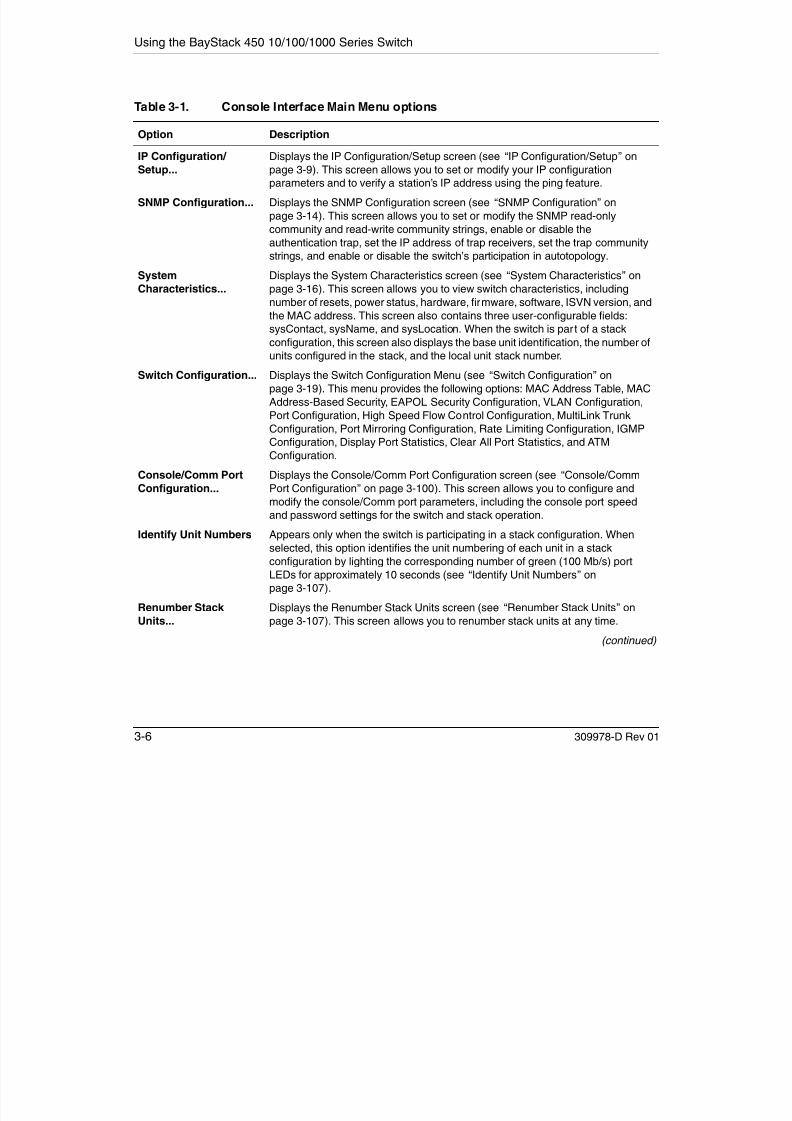
7/23/2019 Baystack 450
http://slidepdf.com/reader/full/baystack-450 166/399
3-6 309978-D Rev 01
sysContact, sysName, and sysLocation. When the switch is part of a stack
configuration, this screen also displays the base unit identification, the number of
units configured in the stack, and the local unit stack number.
Switch Configuration... Displays the Switch Configuration Menu (see “Switch Configuration” on
page 3-19). This menu provides the following options: MAC Address Table, MACAddress-Based Security, EAPOL Security Configuration, VLAN Configuration,
Port Configuration, High Speed Flow Control Configuration, MultiLink Trunk
Configuration, Port Mirroring Configuration, Rate Limiting Configuration, IGMP
Configuration, Display Port Statistics, Clear All Port Statistics, and ATM
Configuration.
Console/Comm Port
Configuration...
Displays the Console/Comm Port Configuration screen (see “Console/Comm
Port Configuration” on page 3-100). This screen allows you to configure and
modify the console/Comm port parameters, including the console port speed
and password settings for the switch and stack operation.
Identify Unit Numbers Appears only when the switch is participating in a stack configuration. When
selected, this option identifies the unit numbering of each unit in a stack
configuration by lighting the corresponding number of green (100 Mb/s) port
LEDs for approximately 10 seconds (see “Identify Unit Numbers” on
page 3-107).
Renumber Stack
Units...
Displays the Renumber Stack Units screen (see “Renumber Stack Units” on
page 3-107). This screen allows you to renumber stack units at any time.(continued)
Using the Console Interface
Display Hardware
Units...
Displays the Hardware Unit Information screen (see “Display Hardware Units” on
page 3-109). This screen lists the switch models, including any installed MDA
and Cascade Modules.
Spanning Tree
Configuration...
Displays the Spanning Tree Configuration Menu (see “Spanning Tree
Configuration” on page 3-110). This menu provides the following options:
Spanning Tree Port Configuration and Display Spanning Tree Switch Settings.
TELNET/SNMP Mgr List
Configuration...
Displays the TELNET/SNMP Manager List Configuration screen (see “TELNET/
SNMP Manager List Configuration” on page 3-118). This screen allows you to
specify up to 10 user-assigned host IP addresses that are allowed TELNET and
SNMP access to the switch. You can set your switch to enable a user at a remote
console terminal to communicate with the BayStack 450 switch as if the console
terminal were directly connected to it. Four active TELNET sessions can be
running at one time in either a standalone switch or a stack configuration.
Software Download... Displays the Software Download screen (see “Software Download” on
page 3 121) This screen allows you to revise the BayStack 450 switch software
Table 3-1. Console Interface Main Menu options (continued)
Option Description

7/23/2019 Baystack 450
http://slidepdf.com/reader/full/baystack-450 167/399
309978-D Rev 01 3-7
page 3-121). This screen allows you to revise the BayStack 450 switch software
image that is located in nonvolatile flash memory.
Configuration File... Displays the Configuration File Download/Upload screen (see “Configuration
File” on page 3-125). This screen allows you to store your switch/stack
configuration parameters on a TFTP server. You can retrieve the configurationparameters for automatically configuring a replacement switch or stack with the
same configuration when required.
Display Event Log Displays the Event Log screen (see “Display Event Log” on page 3-128).
Save Current Settings Saves your current configuration settings without resetting your switch or stack
(see “Save Current Settings” on page 3-131). When you select this option a
confirmation prompt appears. Enter Yes to save your configuration settings;
enter No to abort the option. If the switch is participating in a stack configuration,
additional prompts allow you to save your configuration settings for a specific unitin the stack or for the entire stack.
Reset Resets the switch with your current configuration settings (see “Reset” on
page 3-131). When you select this option a confirmation prompt appears. Enter
Yes to reset the switch; enter No to abort the option. If the switch is participating
in a stack configuration, additional prompts allow you to reset a specific unit in
the stack or the entire stack. When you select this option, the switch resets, runs
a self-test, and then displays the Nortel Networks logo screen.
(continued)

7/23/2019 Baystack 450
http://slidepdf.com/reader/full/baystack-450 168/399
Using the Console Interface
IP Configuration/Setup
The IP Configuration/Setup screen (Figure 3-3) allows you to set or modify theBayStack 450 switch IP configuration parameters and to verify a station’s IPaddress using the ping feature. Data that you enter in the user-configurable fields
takes effect as soon as you press [Enter].Choose IP Configuration/Setup (or press i) from the main menu to open the IP Configuration/Setup screen.
IP Configuration/Setup
BootP Request Mode: [ BootP Disabled ]
Configurable In Use Last BootP------------------- --------------- ---------------
I B d St k IP Add [ 0 0 0 0 ] 0 0 0 0

7/23/2019 Baystack 450
http://slidepdf.com/reader/full/baystack-450 169/399
309978-D Rev 01 3-9
Figure 3-3. IP Configuration/Setup Screen
Note: The read-only fields in this screen are updated based on the BootP modespecified in the BootP Request Mode field. (See “BootP Request Mode” onpage 3-11 for more information.)
In-Band Stack IP Address: [ 0.0.0.0 ] 0.0.0.0In-Band Switch IP Address: [ 0.0.0.0 ] 0.0.0.0In-Band Subnet Mask: [ 0.0.0.0 ] 0.0.0.0 0.0.0.0Default Gateway: [ 0.0.0.0 ] 0.0.0.0 0.0.0.0
IP Address to Ping: [ 0.0.0.0 ]Start Ping: [ No ]
Use space bar to display choices, press <Return> or <Enter> to select choice.
Press Ctrl-R to return to previous menu. Press Ctrl-C to return to Main Menu.
Using the BayStack 450 10/100/1000 Series Switch
Table 3-2 describes the IP Configuration/Setup screen fields.
Table 3-2. IP Configuration/Setup Screen Fields
Field Description
BootP Request
Mode
One of four modes of operation for BootP. (See “BootP Request Mode” on page 3-11 for
details about the four modes.)
Default BootP Disabled
Range BootP Disabled, BootP or Last Address, BootP When Needed, BootP
Always
Configurable Column header for the user-configurable fields in this screen. The data displayed in this
column represents parameters that you can configure (or that are currently configured).
In Use Column header for the read-only fields in this screen. The read-only data displayed inthis column represents data that is currently in use.
Last BootP Column header for the read-only fields in this screen. The read-only data displayed in
this column represents data obtained from the last BootP reply received.

7/23/2019 Baystack 450
http://slidepdf.com/reader/full/baystack-450 170/399
3-10 309978-D Rev 01
In-Band Stack IP
Address
The in-band stack IP address field.
Default 0.0.0.0 (no IP address assigned)
Range Four-octet dotted-decimal notation, where each octet is representedas a decimal value, separated by a decimal point
In-Band Switch
IP Address
The in-band IP address of the BayStack 450 switch. This field is not required for the
operation of the stack. This field cannot use the same IP address used for the stack.
Default 0.0.0.0 (no IP address assigned)
Range Four-octet dotted-decimal notation, where each octet is represented
as a decimal value, separated by a decimal point
Note: When the IP address is entered in the In-Band (Stack/Switch) IP Address field,and the In-Band Subnet Mask field value is not present, the software provides an in-use
default value for the In-Band Subnet Mask field that is based on the class of the IP
address entered in the In-Band (Stack/Switch) IP Address field.
In-Band SubnetMask
The subnet address mask associated with the in-band IP address shown on the screen
(see Note above). Network routers use the subnet mask to determine the network or
subnet address portion of a host’s IP address. The bits in the IP address that contain the
network address (including the subnet) are set to 1 in the address mask, and the bits
that contain the host identifier are set to 0.
Default 0.0.0.0 (no subnet mask assigned)
Range Four-octet dotted-decimal notation, where each octet is represented
as a decimal value, separated by a decimal point
(continued)
Using the Console Interface
Default Gateway The IP address of the default gateway.
Default 0.0.0.0 (no IP address assigned)
Range Four-octet dotted-decimal notation, where each octet is representedas a decimal value, separated by a decimal point
IP Address toPing
The IP address of the station you want to verify using the ping feature.
Default 0.0.0.0 (no IP address assigned)
Range Four-octet dotted-decimal notation, where each octet is represented
as a decimal value, separated by a decimal point
Start Ping Allows you to ping the target IP address entered in the IP Address to Ping field (above).
Default No
Range No, Yes
Table 3-2. IP Configuration/Setup Screen Fields (continued)
Field Description
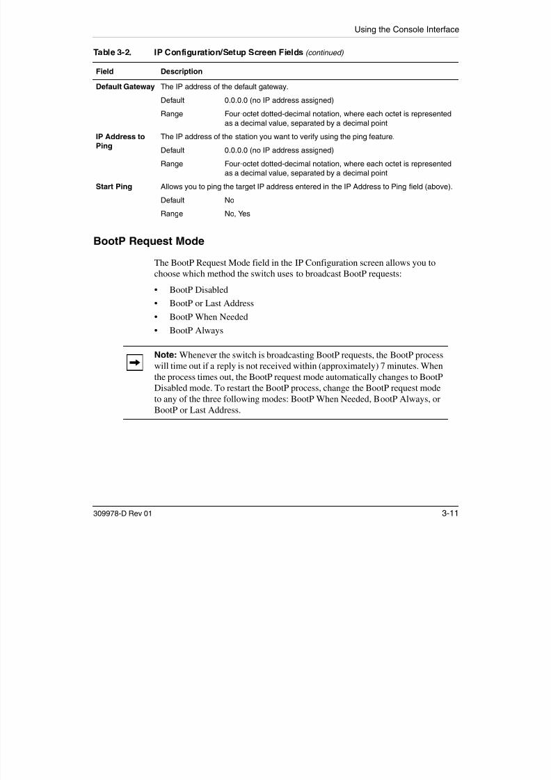
7/23/2019 Baystack 450
http://slidepdf.com/reader/full/baystack-450 171/399
309978-D Rev 01 3-11
BootP Request Mode
The BootP Request Mode field in the IP Configuration screen allows you to
choose which method the switch uses to broadcast BootP requests:• BootP Disabled
• BootP or Last Address
• BootP When Needed
• BootP Always
Note: Whenever the switch is broadcasting BootP requests, the BootP processwill time out if a reply is not received within (approximately) 7 minutes. Whenthe process times out, the BootP request mode automatically changes to BootPDisabled mode. To restart the BootP process, change the BootP request modeto any of the three following modes: BootP When Needed, BootP Always, orBootP or Last Address.
Using the BayStack 450 10/100/1000 Series Switch
BootP Disabled
Allows the switch to be managed only by using the IP address set from theconsole terminal (this is the default mode for your switch).
When selected, this mode operates as follows:
• The switch does not broadcast BootP requests, regardless of whether an IPaddress is set from the console terminal.
• The switch can be managed only by using the in-band IP address set from theconsole terminal.
These actions take effect after the switch is reset or power cycled, even if an IPaddress is not currently in use.
BootP or Last Address
Allows the switch to be managed even if a BootP server is not reachable.

7/23/2019 Baystack 450
http://slidepdf.com/reader/full/baystack-450 172/399
3-12 309978-D Rev 01
When selected, this mode operates as follows:
• When the IP data is entered from the console terminal, the data becomes the
in-band address of the switch and BootP requests are not broadcast. Theswitch can be managed using this in-band IP address.
• When the in-band IP address is not set from the console terminal, the switchbroadcasts BootP requests until it receives a BootP reply containing anin-band IP address. If the switch does not receive a BootP reply that containsan in-band IP address within 10 minutes, the switch uses the last in-band IPaddress it received from a BootP server. This IP information is displayed in
the Last BootP column.
If an IP address is not currently in use, these actions take effect immediately. If anIP address is currently in use, these actions take effect only after the switch is resetor power cycled.
Using the Console Interface
BootP When Needed
Allows the switch to request an IP address if one has not already been set from theconsole terminal.
When selected, this mode operates as follows:
• When the IP data is entered from the console terminal, the data becomes thein-band address of the switch and BootP requests are not broadcast. Theswitch can be managed using this in-band IP address.
• When the in-band IP address is not set from the console terminal, the switchbroadcasts BootP requests until it receives a BootP reply containing an IPaddress. If the switch does not receive a BootP reply that contains an IPaddress, the switch cannot be managed in-band.
If an IP address is not currently in use, these actions take effect immediately. If anIP address is currently in use, these actions take effect only after the switch is resetor power cycled.

7/23/2019 Baystack 450
http://slidepdf.com/reader/full/baystack-450 173/399
309978-D Rev 01 3-13
BootP Always
Allows the switch to be managed only when configured with the IP addressobtained from the BootP server.
When selected, this mode operates as follows:
• The switch continues to broadcast BootP requests, regardless of whether anin-band IP address is set from the console terminal.
• If the switch receives a BootP reply that contains an in-band IP address, the
switch uses this new in-band IP address.
• If the switch does not receive a BootP reply, the switch cannot be managedusing the in-band IP address set from the console terminal.
If an IP address is not currently in use, these actions take effect immediately. If anIP address is currently in use, these actions take effect only after the switch is resetor power cycled.
Using the BayStack 450 10/100/1000 Series Switch
SNMP Configuration
The SNMP Configuration screen (Figure 3-4) allows you to set or modify theSNMP configuration parameters.
Choose SNMP Configuration (or press m) from the main menu to open the SNMPConfiguration screen.
SNMP Configuration
Read-Only Community String: [ public ]Read-Write Community String: [ private ]
Trap #1 IP Address: [ 0.0.0.0 ]Community String: [ ]
Trap #2 IP Address: [ 0.0.0.0 ]Community String: [ ]

7/23/2019 Baystack 450
http://slidepdf.com/reader/full/baystack-450 174/399
3-14 309978-D Rev 01
Figure 3-4. SNMP Configuration Screen
Table 3-3 describes the SNMP Configuration screen fields.
Table 3-3. SNMP Configuration Screen Fields
Field Description
Read-Only
Community String
The community string used for in-band read-only SNMP operations.
Default public
Range Any ASCII string of up to 32 printable characters
(continued)
y g [ ]Trap #3 IP Address: [ 0.0.0.0 ]
Community String: [ ]Trap #4 IP Address: [ 0.0.0.0 ]
Community String: [ ]
Authentication Trap: [ Enabled ]AutoTopology: [ Enabled ]
Enter text, press <Return> or <Enter> when complete.Press Ctrl-R to return to previous menu. Press Ctrl-C to return to Main Menu.
Using the Console Interface
Read-Write
Community String
The community string used for in-band read-write SNMP operations.
Default private
Range Any ASCII string of up to 32 printable characters
Trap #1 IP Address1 Number one of four trap IP addresses. Successive trap IP address fields are
numbered 2, 3, and 4. Each trap address has an associated community
string (see Community String).
Default 0.0.0.0 (no IP address assigned)
Range Four-octet dotted-decimal notation, where each octet is
represented as a decimal value, separated by a decimal
pointCommunity String1 The community string associated with one of the four trap IP addresses (see
Trap #1 IP Address).
Default Zero-length string
R A ASCII t i f t 32 i t bl h t
Table 3-3. SNMP Configuration Screen Fields (continued)
Field Description
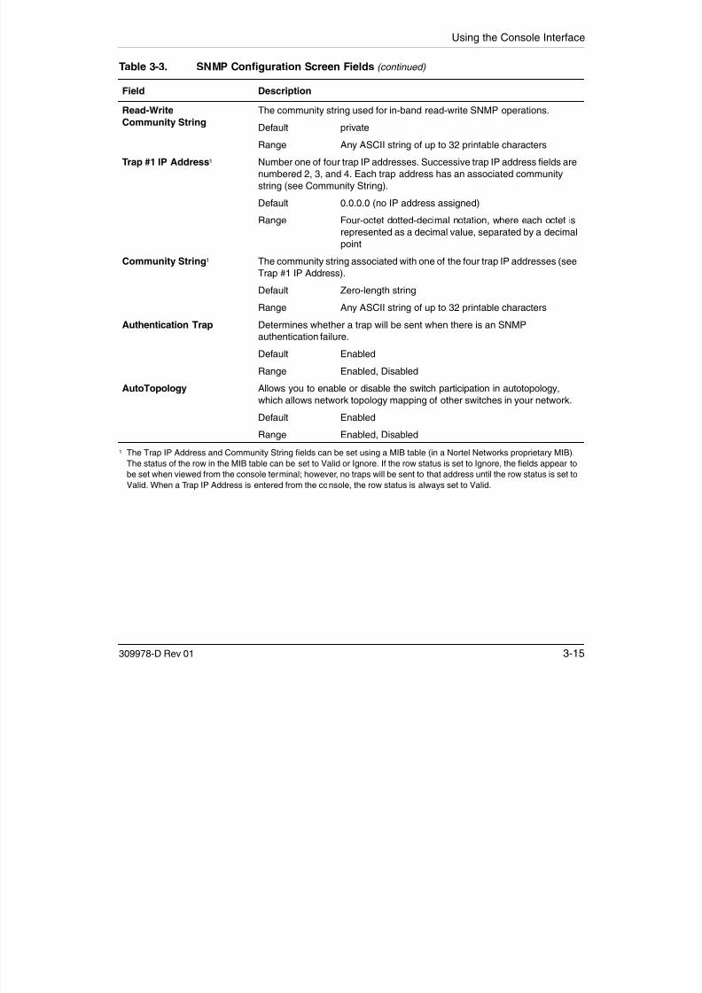
7/23/2019 Baystack 450
http://slidepdf.com/reader/full/baystack-450 175/399
309978-D Rev 01 3-15
Range Any ASCII string of up to 32 printable characters
Authentication Trap Determines whether a trap will be sent when there is an SNMP
authentication failure.
Default Enabled
Range Enabled, Disabled
AutoTopology Allows you to enable or disable the switch participation in autotopology,
which allows network topology mapping of other switches in your network.
Default Enabled
Range Enabled, Disabled
1 The Trap IP Address and Community String fields can be set using a MIB table (in a Nortel Networks proprietary MIB).The status of the row in the MIB table can be set to Valid or Ignore. If the row status is set to Ignore, the fields appear to
be set when viewed from the console terminal; however, no traps will be sent to that address until the row status is set to
Valid. When a Trap IP Address is entered from the console, the row status is always set to Valid.
Using the BayStack 450 10/100/1000 Series Switch
System Characteristics
The System Characteristics screen (Figure 3-5) allows you to view systemcharacteristics. The screen contains three user-configurable fields: sysContact,sysName, and sysLocation.
Choose System Characteristics (or press s) from the main menu to open theSystem Characteristics screen.
System Characteristics
Operation Mode: Stack, Unit # 2
Size Of Stack: 4Base Unit: 1
MAC Address: 00-00-00-00-00-00
Reset Count: 51Last Reset Type: Power Cycle

7/23/2019 Baystack 450
http://slidepdf.com/reader/full/baystack-450 176/399
3-16 309978-D Rev 01
Figure 3-5. System Characteristics Screen
Table 3-4 describes the System Characteristics screen fields.
Last Reset Type: Power CyclePower Status: Primary PowerLocal MDA Type: 1 port 1000Base-LX with LinkSafe, 450-1LR MDAsysDescr: BayStack 450-24T HW:Revx FW:Vx.xx SW:vx.x.x.xx ISVN:x sysObjectID: 1.3.6.1.4.1.45.3.35.1sysUpTime: 00:06:26sysServices: 3sysContact: [ Mario Lento ]sysName: [ Publications ]sysLocation: [ Building 12, Floor 20 ]
Enter text, press <Return> or <Enter> when complete.Press Ctrl-R to return to previous menu. Press Ctrl-C to return to Main Menu.
Using the Console Interface
Table 3-4. System Characteristics Screen Fields
Field Description
Operation Mode Read-only field that indicates the operation mode of the unit, for example:
• When the unit is part of a stack configuration, the (read-only) field indicates the
unit is operational in a stack, and lists the current unit number of this switch. In
this example (see Figure 3-5 on page 3-16), the current unit number is Unit 2.
• When the unit is not part of a stack configuration (operating standalone), the
read-only field indicates the unit is operating as a switch. When in this operation
mode, the Size of Stack and Base Unit fields (see following description) do not
appear.
Size of Stack This read-only field appears only when the switch is participating in a stackconfiguration. This field indicates the number of units configured in the stack
configuration (1 to 8 units maximum).
Base Unit This read-only field appears only when the switch is participating in a stack
configuration. This field indicates the unit number of the switch that is currently

7/23/2019 Baystack 450
http://slidepdf.com/reader/full/baystack-450 177/399
309978-D Rev 01 3-17
operating as the base unit.
MAC Address The MAC address of the BayStack 450 switch or, when the switch is participating in a
stack configuration, the MAC address of the stack configuration.
Reset Count A read-only field that indicates the number of resets since the operational firmware
was first loaded on the switch.
Default 1
Range 0 to 232 -1
Last Reset Type A read-only field that indicates the last type of reset.
Default Power Cycle
Range Power Cycle, Software Download, Management Reset,
Management Factory Reset
Power Status A read-only field that indicates the current power source (primary, RPSU, or both).
Default Primary Power
Range Primary Power, Redundant Power, Primary and Redundant Power
Local MDA Type A read-only field that indicates the MDA type that is configured in this unit.
sysDescr A read-only field that indicates your switch’s model type, the hardware version, thefirmware version, the software version, and the ISVN (see “Stack Operation” on
page 1-39 for important information about the ISVN).
(continued)
Using the BayStack 450 10/100/1000 Series Switch
sysObjectID A read-only field that provides a unique identification of the switch, which contains
the vendor’s private enterprise number.
sysUpTime A read-only field that shows the length of time since the last reset. Note that this field
is updated when the screen is redisplayed.
sysServices A read-only field that indicates the switch’s physical and data link layer functionality.
sysContact The name and phone number of the person responsible for the switch.
Default Zero-length string
Range Any ASCII string of up to 56 printable characters1
sysName A name that uniquely identifies the switch.
Default Zero-length string
Range Any ASCII string of up to 56 printable characters1
sysLocation The physical location of the switch.
Default Zero-length string
Table 3-4. System Characteristics Screen Fields (continued)
Field Description

7/23/2019 Baystack 450
http://slidepdf.com/reader/full/baystack-450 178/399
3-18 309978-D Rev 01
g g
Range Any ASCII string of up to 56 printable characters
1 Although this field can be set to up to 255 characters from a Network Management Station (NMS), only 56 characters
are displayed on the console terminal.
Using the Console Interface
Switch Configuration
The Switch Configuration Menu (Figure 3-6) allows you to set or modify yourswitch configuration.
Choose Switch Configuration (or press w) from the main menu to open the SwitchConfiguration Menu.
Note: The High Speed Flow Control Configuration option appears only whenan optional gigabit MDA is installed.
Switch Configuration Menu

7/23/2019 Baystack 450
http://slidepdf.com/reader/full/baystack-450 179/399
309978-D Rev 01 3-19
Figure 3-6. Switch Configuration Menu
Table 3-5 describes the Switch Configuration Menu options.
MAC Address TableMAC Address-Based Security...EAPOL Security Configuration...
VLAN Configuration...Port Configuration...High Speed Flow Control Configuration...MultiLink Trunk Configuration...Port Mirroring Configuration...Rate Limiting Configuration...IGMP Configuration...Display Port StatisticsClear All Port StatisticsATM Configuration...
Return to Main Menu
Use arrow keys to highlight option, press <Return> or <Enter> to select option.Press Ctrl-R to return to previous menu. Press Ctrl-C to return to Main Menu.
Using the BayStack 450 10/100/1000 Series Switch
Table 3-5. Switch Configuration Menu Options
Option Description
MAC Address Table Displays the MAC Address Table screen (see “MAC Address Table” on
page 3-22). This screen allows you to view all MAC addresses andtheir associated port or trunk that the switch has learned, or to search
for a particular MAC address (to see if the switch has learned the
address).
MAC Address-Based Security... Displays the MAC Address Security Configuration Menu (see “MAC
Address-Based Security” on page 3-24). This menu provides the
following options: MAC Address Security Configuration, MAC Address
Security Port Configuration, MAC Address Security Port Lists, and
MAC Address Security Table. This menu allows you to set up yourMAC address-based security for your switch.
EAPOL Security Configuration... Displays the EAPOL Security Configuration screen (see “EAPOL
Security Configuration” on page 3-40). This screen allows you to
configure your switch for EAPOL security.

7/23/2019 Baystack 450
http://slidepdf.com/reader/full/baystack-450 180/399
3-20 309978-D Rev 01
VLAN Configuration... Displays the VLAN Configuration Menu (see “VLAN Configuration
Menu” on page 3-44). This menu provides the following options: VLAN
Configuration, VLAN Port Configuration, VLAN Display by Port, and
Traffic Class Configuration. This menu allows you to create and modify
VLANs.
Port Configuration... Displays the Port Configuration screen (see “Port Configuration” on
page 3-59). This screen allows you to configure a specific switch port,
all switch ports or, when in a stack configuration, all stack ports.
High Speed Flow Control
Configuration...
Appears only when an optional gigabit MDA is installed in the Uplink
Module slot. When the gigabit MDA is installed, selecting this option
displays the High Speed Flow Control Configuration screen (see “HighSpeed Flow Control Configuration” on page 3-62).
MultiLink Trunk Configuration... Displays the MultiLink Trunk Configuration Menu (see “MultiLink Trunk
Configuration” on page 3-64). This menu provides the following
options: MultiLink Trunk Configuration and MultiLink Trunk Utilization.
This menu allows you to create and modify trunks, and to monitor the
bandwidth utilization of configured trunks.
Port Mirroring Configuration... Displays the Port Mirroring Configuration screen (see “Port Mirroring
Configuration” on page 3-71). This screen allows you to designate asingle switch port as a traffic monitor for up to two specified ports or
addresses.
(continued)
Using the Console Interface
Rate Limiting Configuration... Displays the Rate Limiting Configuration screen (see “Rate Limiting
Configuration” on page 3-75). This screen allows you to limit the
forwarding rate of broadcast and IP multicast packets.
IGMP Configuration... Displays the IGMP Configuration Menu (see “IGMP ConfigurationMenu” on page 3-78). This menu allows you to optimize IP multicast
traffic by setting up IGMP port memberships that filter IP multicast on
a per port basis (see “IGMP Snooping” on page 1-69 for more
information about this feature).
Display Port Statistics Displays the Port Statistics screen (see “Port Statistics” on
page 3-85). This screen allows you to view detailed information about
any switch port.
Clear All Port Statistics Allows you to clear all por t statistics. This option is followed by screen
prompts that precede a choice of actions:
• If the switch is operating standalone , choose one of the following:
• Yes, to clear all port statistics for all switch ports
• No, to abort the option
• If the switch is participating in a stack configuration choose one of
Table 3-5. Switch Configuration Menu Options (continued)
Option Description
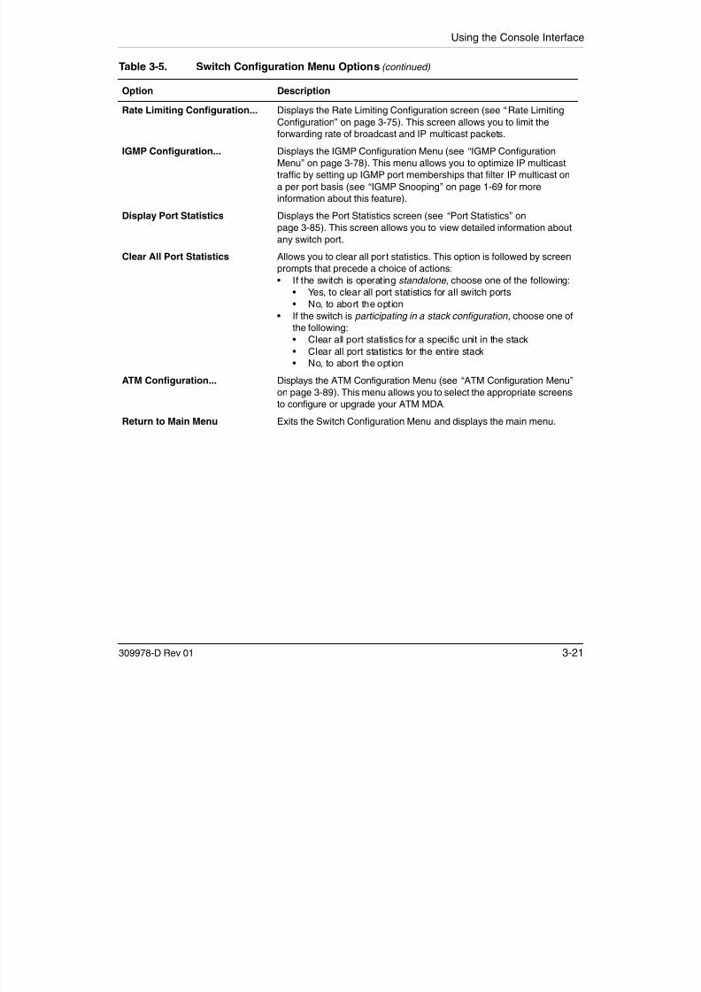
7/23/2019 Baystack 450
http://slidepdf.com/reader/full/baystack-450 181/399
309978-D Rev 013-21
• If the switch is participating in a stack configuration , choose one of
the following:
• Clear all port statistics for a specific unit in the stack
• Clear all port statistics for the entire stack• No, to abort the option
ATM Configuration... Displays the ATM Configuration Menu (see “ATM Configuration Menu”
on page 3-89). This menu allows you to select the appropriate screens
to configure or upgrade your ATM MDA.
Return to Main Menu Exits the Switch Configuration Menu and displays the main menu.
Using the BayStack 450 10/100/1000 Series Switch
MAC Address Table
The MAC Address Table screen (Figure 3-7) allows you to view learned MACaddresses or to search for a specific MAC address.
The MAC Address Table screen also operates in conjunction with the Port
Mirroring Configuration screen. When you configure a switch for MACaddress-based port mirroring, you can use the MAC Address Table screen to findan address, and enter the address directly from this screen. You can enteraddresses from either screen, but you must return to the Port MirroringConfiguration screen to activate the feature (see “Port Mirroring Configuration”on page 3-71).
Choose MAC Address Table (or press m) from the Switch Configuration Menu toopen the MAC Address Table screen
Note: This screen does not refresh dynamically to show new entries. Torefresh the screen, press [Ctrl]-R to return to the previous menu.

7/23/2019 Baystack 450
http://slidepdf.com/reader/full/baystack-450 182/399
3-22 309978-D Rev 01
open the MAC Address Table screen.
Figure 3-7. MAC Address Table Screen
MAC Address Table
Aging Time: [ 300 seconds ]Find an Address: [ 00-00-00-00-00-00 ]
Port Mirroring Address A: [ 00-44-55-44-55-22 ]Port Mirroring Address B: [ 00-33-44-33-22-44 ]
00-60-FX-00-02-3000-00-AX-85-2X-26 Port: 100-60-XX-12-02-15 Port: 100-08-FX-1D-4X-38 Trunk:3
End of Address Table. Press Ctrl-P to see previous display.Press Ctrl-R to return to previous menu. Press Ctrl-C to return to Main Menu.
Using the Console Interface
Table 3-6 describes the MAC Address Table screen fields.
Table 3-6. MAC Address Table Screen Fields
Field Description
Aging Time Specifies how long a learned MAC address remains in the switch’s
forwarding database. If an entry is inactive for a period of time that exceedsthe specified aging time, the address is removed.
Default 300 seconds
Range 10 to 1,000,000 seconds
Find an Address Allows the user to search for a specific MAC address.
Default 00-00-00-00-00-00 (no MAC address assigned)
Range 00-00-00-00-00-00 to FF-FF-FF-FF-FF-FFPort Mirroring Address A Appears only when you select any of the five address-based monitoring
modes from the Port Mirroring Configuration screen. When you enter a MAC
address in this field, it is also configured into the Port Mirroring Configuration
screen. Conversely, when you enter the MAC address from the Port Mirroring
Configuration screen, it also appears in this screen. See “Port Mirroring

7/23/2019 Baystack 450
http://slidepdf.com/reader/full/baystack-450 183/399
309978-D Rev 01 3-23
Configuration” on page 3-71 for more information.
Default 00-00-00-00-00-00 (no MAC address assigned)
Range 00-00-00-00-00-00 to FF-FF-FF-FF-FF-FF
Port Mirroring Address B Appears only when you select any of the two address-based monitoring
modes that use Address B from the Port Mirroring Configuration screen.
When you enter a MAC address in this field, it is also configured into the Port
Mirroring Configuration screen. Conversely, when you enter the MAC
address from the Port Mirroring Configuration screen, it also appears in this
screen. See “Port Mirroring Configuration” on page 3-71 for more
information.
Default 00-00-00-00-00-00 (no MAC address assigned)
Range 00-00-00-00-00-00 to FF-FF-FF-FF-FF-FF
Using the BayStack 450 10/100/1000 Series Switch
MAC Address-Based Security
The MAC Address Security Configuration Menu (Figure 3-8) allows you tochoose the appropriate screen to specify a range of system responses tounauthorized network access to your switch. The system response can range fromsending a trap to disabling the port. The network access control is based on the
MAC addresses of the authorized stations.
You can specify a list of up to 448 MAC addresses (within a single standaloneswitch or within one or more units in a single stacked configuration) that areauthorized to access the switch or stack. You can also specify the ports that eachMAC address is allowed to access.
The options for allowed port access include: NONE, ALL, and single or multipleports that are specified in a list, for example, 1/1-4, 2/6, 3/9, etc., (see “AcceleratorKeys for Repetitive Tasks” on page 3-35).
When the switch software detects a security violation, you can set the system torespond in any of the following ways:
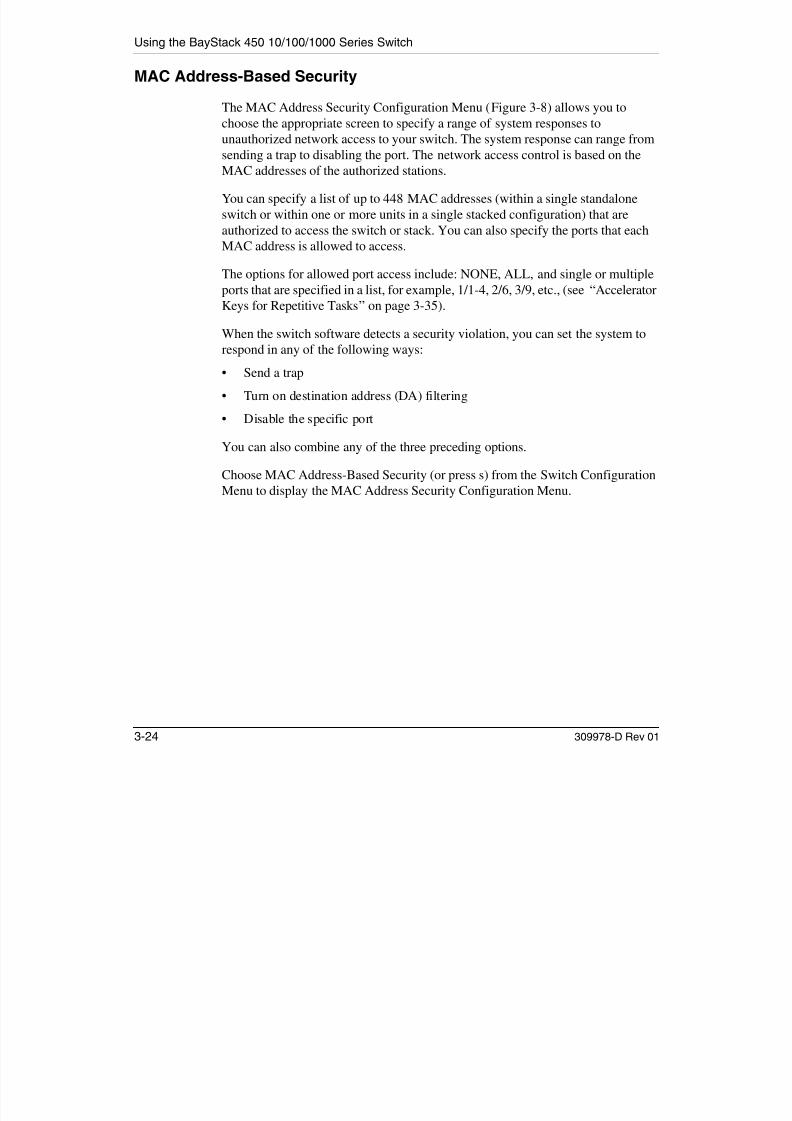
7/23/2019 Baystack 450
http://slidepdf.com/reader/full/baystack-450 184/399
3-24 309978-D Rev 01
• Send a trap
• Turn on destination address (DA) filtering• Disable the specific port
You can also combine any of the three preceding options.
Choose MAC Address-Based Security (or press s) from the Switch ConfigurationMenu to display the MAC Address Security Configuration Menu.
Using the Console Interface
MAC Address Security Configuration Menu
MAC Address Security Configuration...MAC Address Security Port Configuration...MAC Address Security Port Lists...MAC Address Security Table...Return to Switch Configuration Menu
Use arrow keys to highlight option, press <Return> or <Enter> to select option.

7/23/2019 Baystack 450
http://slidepdf.com/reader/full/baystack-450 185/399
309978-D Rev 01 3-25
Figure 3-8. MAC Address Security Configuration Menu
Table 3-7 describes the MAC Address Security Configuration Menu options.
Press Ctrl-R to return to previous menu. Press Ctrl-C to return to Main Menu.
Using the BayStack 450 10/100/1000 Series Switch
Table 3-7. MAC Address Security Configuration Menu Options
Option Description
MAC Address Security
Configuration...
Displays the MAC Address Security Configuration screen (see “MAC
Address Security Configuration” on page 3-26). This screen allows you toenable or disable the MAC Address Security feature.
MAC Address Security
Port Configuration...
Displays the MAC Address Security Port Configuration screen (see “MAC
Address Security Port Configuration” on page 3-30). This screen allows you
to enable or disable MAC Security for each port.
MAC Address Security
Port Lists...
Displays the MAC Address Security Port Lists screen (see “MAC Address
Security Port Lists” on page 3-33). This screen allows you to create port lists
that can be used as an allowed source port list for a MAC address in the
MAC Address Security Table screen.
MAC Address SecurityTable...
Displays the MAC Address Security Table screen (see “MAC Address
Security Port Configuration” on page 3-30). This screen allows you to specify
the MAC addresses that are allowed to access the switch.
Return to Switch
Configuration Menu
Exits the MAC Address Security Configuration Menu and displays the Switch
Configuration Menu

7/23/2019 Baystack 450
http://slidepdf.com/reader/full/baystack-450 186/399
3-26 309978-D Rev 01
MAC Address Security Configuration
The MAC Address Security Configuration screen (Figure 3-9) allows you toenable (or disable) the MAC Address Security feature and to specify theappropriate system response to any unauthorized network access to your switch.
Choose MAC Address Security Configuration (or press c) from the MAC Address
Security Configuration Menu to display the MAC Address Security Configurationscreen.
Configuration Menu... Configuration Menu.
Using the Console Interface
MAC Address Security Configuration
MAC Address Security: [ Disabled ]MAC Address Security SNMP-Locked: [ Disabled ]Partition Port on Intrusion: [ Disabled ]
DA Filtering on Intrusion: [ Disabled ]Generate SNMP Trap on Intrusion: [ Disabled ]
MAC Security Table
Clear by Ports: [ ]
Learn by Ports: [ ]
Current Learning Mode: [ Disabled ]
Use space bar to display choices, press <Return> or <Enter> to select choice.Press Ctrl R to return to previous menu Press Ctrl C to return to Main Menu

7/23/2019 Baystack 450
http://slidepdf.com/reader/full/baystack-450 187/399
309978-D Rev 01 3-27
Figure 3-9. MAC Address Security Configuration Screen
Table 3-8 describes the MAC Address Security Configuration screen fields.
Press Ctrl-R to return to previous menu. Press Ctrl-C to return to Main Menu.
Using the BayStack 450 10/100/1000 Series Switch
Table 3-8. MAC Address Security Configuration Screen Fields
Field Description
MAC Address Security When set to Enabled, the software checks source MAC addresses of packets
that arrive on secure ports against MAC addresses listed in the MAC AddressSecurity Table for allowed membership (see “MAC Address Security Port
Configuration” on page 3-30). If the software detects any source MAC address
that is not an allowed member, a MAC intrusion event is registered.
Default Disabled
Range Disabled, Enabled
MAC Address Security
SNMP-Locked
When this field is set to Enabled, the MAC Address Security screens cannot
be modified using SNMP.Default Disabled
Range Disabled, Enabled
Partition Port on Intrusion This field value determines how the switch reacts to an intrusion event. When
an intrusion event is detected (see MAC Address Security field description)
the specified port is set to Disabled (partitioned from other switch ports).
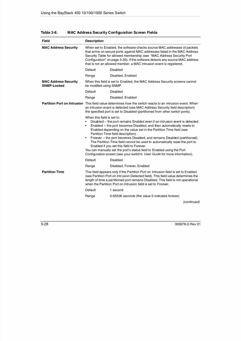
7/23/2019 Baystack 450
http://slidepdf.com/reader/full/baystack-450 188/399
3-28 309978-D Rev 01
p p (p p )
When this field is set to:
• Disabled -- the port remains Enabled even if an intrusion event is detected.• Enabled -- the port becomes Disabled, and then automatically resets to
Enabled depending on the value set in the Partition Time field (see
Partition Time field description).
• Forever -- the port becomes Disabled, and remains Disabled (partitioned).
The Partition Time field cannot be used to automatically reset the port to
Enabled if you set this field to Forever.
You can manually set the port’s status field to Enabled using the Port
Configuration screen (see your switch’s User Guide for more information).
Default Disabled
Range Disabled, Forever, Enabled
Partition Time This field appears only if the Partition Port on Intrusion field is set to Enabled
(see Partition Port on Intrusion Detected field). This field value determines the
length of time a partitioned port remains Disabled. This field is not operational
when the Partition Port on Intrusion field is set to Forever.
Default 1 second
Range 0-65536 seconds (the value 0 indicates forever)
(continued)
Using the Console Interface
DA Filtering on Intrusion When set to Enabled, this field isolates the intruding node by filtering
(discarding) packets sent to that MAC address.
Default Disabled
Range Disabled, Enabled
Generate SNMP Trap onIntrusion
When set to Enabled and a MAC intrusion event is detected, the software
issues an SNMP trap message to all registered SNMP trap addresses.
Default Disabled
Range Disabled, Enabled
Clear by Ports This field clears the specified port (or ports) that are listed in the Allowed Source field of the MAC Address Security Table screen (see “MACAddress Security Table” on page 3-37). When you specify a port (or ports) to
be cleared using this field, the specific port (or ports) will be cleared for each
of the entries listed in the MAC Address Security Table. If you clear the
Allowed Source field (leaving a blank field) for any entry, the associated MAC
address for that entry is also cleared. This field also clears the associated Port
List field in the MAC Address Security Port Lists screen (Figure 3-13).
Table 3-8. MAC Address Security Configuration Screen Fields (continued)
Field Description
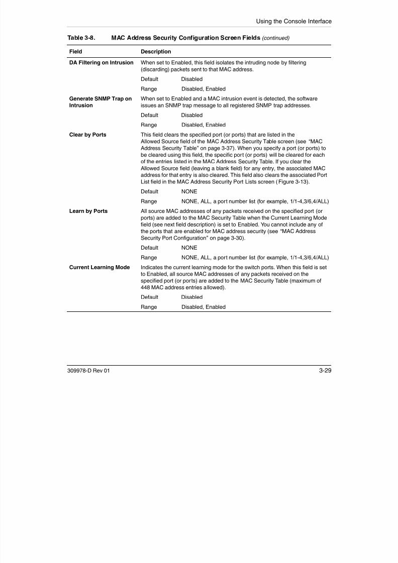
7/23/2019 Baystack 450
http://slidepdf.com/reader/full/baystack-450 189/399
309978-D Rev 01 3-29
Default NONE
Range NONE, ALL, a port number list (for example, 1/1-4,3/6,4/ALL)
Learn by Ports All source MAC addresses of any packets received on the specified port (or
ports) are added to the MAC Security Table when the Current Learning Mode
field (see next field description) is set to Enabled. You cannot include any of
the ports that are enabled for MAC address security (see “MAC Address
Security Port Configuration” on page 3-30).
Default NONE
Range NONE, ALL, a port number list (for example, 1/1-4,3/6,4/ALL)Current Learning Mode Indicates the current learning mode for the switch ports. When this field is set
to Enabled, all source MAC addresses of any packets received on the
specified port (or ports) are added to the MAC Security Table (maximum of
448 MAC address entries allowed).
Default Disabled
Range Disabled, Enabled
Using the BayStack 450 10/100/1000 Series Switch
MAC Address Security Port Configuration
The MAC Address Security Port Configuration screen (Figures 3-10 and 3-11)allows you to enable or disable the MAC address security for each port.
Choose MAC Address Security Port Configuration (or press p) from the MACAddress Security Configuration Menu to display the MAC Address Security PortConfiguration screen.
Note: You cannot enable MAC address security on a port that is currentlyconfigured for EAPOL-based security.
MAC Address Security Port ConfigurationUnit: [ 1 ]
Port Trunk Security---- ----- ------------1 [ Disabled ]2 [ Disabled ]3 [ Disabled ]

7/23/2019 Baystack 450
http://slidepdf.com/reader/full/baystack-450 190/399
3-30 309978-D Rev 01
Figure 3-10. MAC Address Security Port Configuration (Screen 1 of 2)
4 [ Disabled ]5 [ Disabled ]6 [ Disabled ]7 [ Disabled ]8 [ Disabled ]9 [ Disabled ]10 [ Disabled ]11 [ Disabled ]12 [ Disabled ]13 [ Disabled ]14 [ Disabled ]
More...
Press Ctrl-N to display choices for additional ports..Use space bar to display choices, press <Return> or <Enter> to select choice.Press Ctrl-R to return to previous menu. Press Ctrl-C to return to Main Menu.
Using the Console Interface
MAC Address Security Port ConfigurationUnit: [ 1 ]
Port Trunk Security---- ----- ------------15 [ Disabled ]16 [ Disabled ]
17 [ Disabled ]18 [ Disabled ]19 [ Disabled ]20 [ Disabled ]21 [ Disabled ]22 [ Disabled ]23 [ Disabled ]24 [ Disabled ]
Switch [ Enable ]Stack [ Enable ]
Press Ctrl-P to display choices for ports 1-14.Use space bar to display choices, press <Return> or <Enter> to select choice.Press Ctrl-R to return to previous menu. Press Ctrl-C to return to Main Menu.

7/23/2019 Baystack 450
http://slidepdf.com/reader/full/baystack-450 191/399
309978-D Rev 01 3-31
Figure 3-11. MAC Address Security Port Configuration (Screen 2 of 2)
Table 3-9 describes the MAC Address Security Port Configuration screen fields.
Using the BayStack 450 10/100/1000 Series Switch
Table 3-9. MAC Address Security Port Configuration Screen Fields
Field Description
Unit Allows you to select the unit number (when stacking is configured) to view or
configure. To view or configure another unit, type its unit number and press[Enter], or press the spacebar to toggle the unit numbers.
Port Indicates the switch port numbers that correspond to the field values in that
row of the screen (for example, the field values in row 2 apply to switch port 2).
The values that you set in the Switch row will affect all switch ports and, when
the switch is part of a stack, the values that you set in the Stack row will affect
all ports in the entire stack.
Trunk The read-only data displayed in this column indicates the MultiLink Trunks that
correspond to the switch ports specified in the Trunk Members fields of theTrunk Configuration screen.
Security Allows you to enable or disable security for the specified port. Note: If an (optional) BayStack 450-2M3/2S3 MDA is installed in your switch,
the Security field value you set for a single LEC VPort applies automatically to
the three remaining LEC VPorts.

7/23/2019 Baystack 450
http://slidepdf.com/reader/full/baystack-450 192/399
3-32 309978-D Rev 01
t e t ee e a g C o ts
Default Disabled
Range Disabled, Enabled
Using the Console Interface
MAC Address Security Port Lists
The MAC Address Security Port Lists screens allow you to create port lists thatcan be used as allowed source port lists for a specified MAC address in the MACAddress Security Table screen. You can create as many as 32 port lists, using up tofive MAC Address Security Port Lists screens (see Figure 3-12).
MAC Address Security Port Lists
Entry Port List----- ---------S1 [ ]
S2 [ ]
S3 [ ]
S4 [ ]
S5 [ ]
S6 [ ]
S7 [ ]
More...
Press Ctrl-N to display next screen.Enter unit/port,"1/NONE","1/ALL","2/3,4/7-9",press <Return> or <Enter> when donePress Ctrl-R to return to previous menu. Press Ctrl-C to return to Main Menu.
MAC Address Security Port Lists
Entry Port List----- ---------S8 [ ]
S9 [ ]
S10 [ ]
S11 [ ]
S12 [ ]
S13 [ ]
S14 [ ]
More...
Press Ctrl-N to display next screen. Press Ctrl-P to display previous screen.Enter unit/port,"1/NONE","1/ALL","2/3,4/7-9",press <Return> or <Enter> when donePress Ctrl-R to return to previous menu. Press Ctrl-C to return to Main Menu.
MAC Address Security Port Lists
Entry Port List----- ---------S15 [ ]
S16 [ ]
S17 [ ]
S18 [ ]
S19 [ ]
S20 [ ]
S21 [ ]
M
MAC Address Security Port Lists
Entry Port List----- ---------S22 [ ]
S23 [ ]
S24 [ ]
S25 [ ]
Screen 1
Screen 2
Screen 3
Screen 4
Screen 5
MAC Address Security Port Lists
Entry Port List----- ---------S29 [ ]
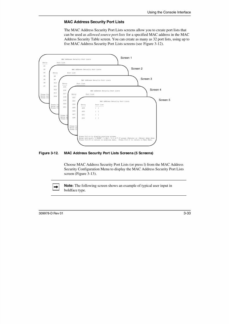
7/23/2019 Baystack 450
http://slidepdf.com/reader/full/baystack-450 193/399
309978-D Rev 01 3-33
Figure 3-12. MAC Address Security Port Lists Screens (5 Screens)
Choose MAC Address Security Port Lists (or press l) from the MAC AddressSecurity Configuration Menu to display the MAC Address Security Port Listsscreen (Figure 3-13).
Note: The following screen shows an example of typical user input inboldface type.
More...
Press Ctrl-N to display next screen. Press Ctrl-P to display previous screen.Enter unit/port,"1/NONE","1/ALL","2/3,4/7-9",press <Return> or <Enter> when donePress Ctrl-R to return to previous menu. Press Ctrl-C to return to Main Menu.
S26 [ ]
S27 [ ]
S28 [ ]
More...
Press Ctrl-N to display next screen. Press Ctrl-P to display previous screen.Enter unit/port,"1/NONE","1/ALL","2/3,4/7-9",press <Return> or <Enter> when donePress Ctrl-R to return to previous menu. Press Ctrl-C to return to Main Menu.
S30 [ ]
S31 [ ]
S32 [ ]
Press Ctrl-P to display previous screen.Enter unit/port,"1/NONE","1/ALL","2/3,4/7-9",press <Return> or <Enter> when donePress Ctrl-R to return to previous menu. Press Ctrl-C to return to Main Menu.
Using the BayStack 450 10/100/1000 Series Switch
MAC Address Security Port Lists
Entry Port List----- ---------S1 [ 1/1-7,2/1-7,2/9,3/1-4,4/12 ]
S2 [ 2/1-7,2/9,4/3-5 ]
S3 [ 1/3,2/7,3/1-4 ]
S4 [ 4/12 ]
S5 [ 1/NONE,2/NONE,3/NONE,4/NONE ]
S6 [ 1/ALL,2/ALL,3/ALL,4/ALL ]
S7 [ 3/ALL ]
More...
Press Ctrl-N to display next screen.Enter unit/port,"1/NONE","1/ALL","2/3,4/7-9",press <Return> or <Enter> when donePress Ctrl-R to return to previous menu. Press Ctrl-C to return to Main Menu.

7/23/2019 Baystack 450
http://slidepdf.com/reader/full/baystack-450 194/399
3-34 309978-D Rev 01
Figure 3-13. MAC Address Security Port Lists Screen
Table 3-10 describes the MAC Address Security Port Lists screen fields.
Table 3-10. MAC Address Security Port Lists Screen Fields
Field Description
Entry Indicates the port list number (S1 to S32) that corresponds to the values you
set in the Port List field.
Port List Allows you to create a port list that you can use as an “Allowed Source” in the
MAC Address Security Table screen (see “Port List Syntax” on page 3-35).
Using the Console Interface
Port List Syntax
When you enter a port list in a stack configuration, you must specify either a unit/port number list, NONE, or ALL. In a stack configuration, ALL indicates allof the stack ports; in a standalone switch, ALL indicates all of the switch ports.
A unit/port number list is composed of one or more list items, each of which canbe a single number or a range of numbers (where the number represents one ormore ports). If a list item is preceded by a number and then a slash (/), the number
represents a stack unit.For example, 1/1-7,2/1-7,2/9,3/1-4,4/12 is a valid unit/port number list (see entryS1 in Figure 3-13 on page 3-34).
It represents the following port order:
• Unit 1: ports 1 to 7
Note: NONE and ALL must be entered in uppercase characters as shown inthe screen prompt.

7/23/2019 Baystack 450
http://slidepdf.com/reader/full/baystack-450 195/399
309978-D Rev 01 3-35
• Unit 2: ports 1 to 7 and port 9• Unit 3: ports 1 to 4
• Unit 4: port 12.
See “Accelerator Keys for Repetitive Tasks” following this section for moreinformation about creating port lists.
Accelerator Keys for Repetitive Tasks
You can use certain keystrokes as “accelerator keys” to help speed up repetitivetasks. For example, suppose you want to modify the Port List field in the MACAddress Security Port List screen (Figure 3-13 on page 3-34). You can modify theport list in any of the following ways:
• Add a new port to an existing port number list
• Remove a port from an existing port number list
• Copy an existing field into an adjacent field
Using the BayStack 450 10/100/1000 Series Switch
Adding a New Port to an Existing Port Number List:
In the example shown in Figure 3-13 on page 3-34, S3 shows the Port List fieldvalues as:
1/3,2/7,3/1-4
If you want to add another port (for example, port 2/9) to the existing port numberlist, you could highlight the field and then type another port list, including the newport number: 1/3,2/7,2/9, 3/1-4 [Enter].
This works but is quite time consuming.
Instead, you can highlight the field, and then enter +2/9 [Enter]. The existing fieldkeeps the previous list, and adds the new port number (2/9) between ports 2/7 and 3/14.
(If you had chosen to add port 2/8 to the existing port number list, the field acceptsthe new port 2/8 but shows the new port number list field as: 1/3,2/7-8,3/1-4.)
Removing a Port from an Existing Port Number List:

7/23/2019 Baystack 450
http://slidepdf.com/reader/full/baystack-450 196/399
3-36 309978-D Rev 01
To remove a port from the port number list, use the minus sign (-) characterinstead of the plus sign (+) character as described above.
Copying an Existing Field into an Adjacent Field:
You can use the period (.) character to copy a previously entered field value intothe field directly next to it. For example, to copy the Allowed Source S3 (shown inFigure 3-15 on page 3-38) into the next field (entry 6):
1. Enter a MAC address into the next MAC Address field.
2. Highlight the (blank) Allowed Source field.
3. Enter the period character (.) and press [Enter].
The port number list from the previous entry is copied into the new field.
Using the Console Interface
MAC Address Security Table
The MAC Address Security Table screen allows you to specify the ports that eachMAC address is allowed to access. You must also include the MAC addresses of any routers and switches that are connected to any secure ports.
There are 16 available MAC Address Security Table screens you can use to createas many as 448 MAC address entries. Twenty-eight MAC address entries aredisplayed on each screen (see Figure 3-14).
MAC Address Security TableFind an Address: [ 00-00-00-00-00-00 ]
MAC Address Allowed Source MAC Address Allowed Source----------- -------------- ----------- --------------
[ - - - - - ] [ ] [ - - - - - ] [ ][ - - - - - ] [ ] [ - - - - - ] [ ][ - - - - - ] [ ] [ - - - - - ] [ ]
[ - - - - - ] [ ] [ - - - - - ] [ ][ - - - - - ] [ ] [ - - - - - ] [ ][ - - - - - ] [ ] [ - - - - - ] [ ][ - - - - - ] [ ] [ - - - - - ] [ ][ - - - - - ] [ ] [ - - - - - ] [ ][ - - - - - ] [ ] [ - - - - - ] [ ][ - - - - - ] [ ] [ - - - - - ] [ ][ - - - - - ] [ ] [ - - - - - ] [ ][ - - - - - ] [ ] [ - - - - - ] [ ][ - - - - - ] [ ] [ - - - - - ] [ ][ - - - - - ] [ ] [ - - - - - ] [ ]
Screen 1 More...
Press Ctrl-N to display next screen.Enter MAC Address, xx-xx-xx-xx-xx-xx, press <Return> or <Enter> when complete.Press Ctrl-R to return to previous menu. Press Ctrl-C to return to Main Menu.
Screen 1

7/23/2019 Baystack 450
http://slidepdf.com/reader/full/baystack-450 197/399
309978-D Rev 01 3-37
Figure 3-14. MAC Address Security Table Screens (16 Screens)
Choose MAC Address Security Table (or press t) from the MAC Address SecurityConfiguration Menu to display the MAC Address Security Table screen.
MAC Address Security TableFind an Address: [ 00-00-00-00-00-00 ]
MAC Address Allowed Source MAC Address Allowed Source----------- -------------- ----------- --------------
[ - - - - - ] [ ] [ - - - - - ] [ ][ - - - - - ] [ ] [ - - - - - ] [ ][ - - - - - ] [ ] [ - - - - - ] [ ][ - - - - - ] [ ] [ - - - - - ] [ ][ - - - - - ] [ ] [ - - - - - ] [ ][ - - - - - ] [ ] [ - - - - - ] [ ][ - - - - - ] [ ] [ - - - - - ] [ ][ - - - - - ] [ ] [ - - - - - ] [ ][ - - - - - ] [ ] [ - - - - - ] [ ][ - - - - - ] [ ] [ - - - - - ] [ ][ - - - - - ] [ ] [ - - - - - ] [ ][ - - - - - ] [ ] [ - - - - - ] [ ][ - - - - - ] [ ] [ - - - - - ] [ ][ - - - - - ] [ ] [ - - - - - ] [ ]
Screen 1 More...
Press Ctrl-N to display next screen.
Enter MAC Address, xx-xx-xx-xx-xx-xx, press <Return> or <Enter> when complete.Press Ctrl-R to return to previous menu. Press Ctrl-C to return to Main Menu.
MAC Address Security TableFind an Address: [ 00-00-00-00-00-00 ]
MAC Address Allowed Source MAC Address Allowed Source----------- -------------- ----------- --------------
[ - - - - - ] [ ] [ - - - - - ] [ ][ - - - - - ] [ ] [ - - - - - ] [ ][ - - - - - ] [ ] [ - - - - - ] [ ][ - - - - - ] [ ] [ - - - - - ] [ ][ - - - - - ] [ ] [ - - - - - ] [ ][ - - - - - ] [ ] [ - - - - - ] [ ][ - - - - - ] [ ] [ - - - - - ] [ ][ - - - - - ] [ ] [ - - - - - ] [ ][ - - - - - ] [ ] [ - - - - - ] [ ][ - - - - - ] [ ] [ - - - - - ] [ ][ - - - - - ] [ ] [ - - - - - ] [ ][ - - - - - ] [ ] [ - - - - - ] [ ][ - - - - - ] [ ] [ - - - - - ] [ ][ - - - - - ] [ ] [ - - - - - ] [ ]
Screen 1 More...
Press Ctrl-N to display next screen.Enter MAC Address, xx-xx-xx-xx-xx-xx, press <Return> or <Enter> when complete.Press Ctrl-R to return to previous menu. Press Ctrl-C to return to Main Menu.
MAC Address Security TableFind an Address: [ 00-00-00-00-00-00 ]
MAC Address Allowed Source MAC Address Allowed Source----------- -------------- ----------- --------------
[ - - - - - ] [ ] [ - - - - - ] [ ][ - - - - - ] [ ] [ - - - - - ] [ ][ - - - - - ] [ ] [ - - - - - ] [ ][ - - - - - ] [ ] [ - - - - - ] [ ][ - - - - - ] [ ] [ - - - - - ] [ ][ - - - - - ] [ ] [ - - - - - ] [ ][ - - - - - ] [ ] [ - - - - - ] [ ][ - - - - - ] [ ] [ - - - - - ] [ ][ - - - - - ] [ ] [ - - - - - ] [ ]
[ - - - - - ] [ ] [ - - - - - ] [ ][ - - - - - ] [ ] [ - - - - - ] [ ][ - - - - - ] [ ] [ - - - - - ] [ ][ - - - - - ] [ ] [ - - - - - ] [ ][ - - - - - ] [ ] [ - - - - - ] [ ]
Screen 16
Press Ctrl-P to display previous screen.Enter MAC Address, xx-xx-xx-xx-xx-xx, press <Return> or <Enter> when complete.Press Ctrl-R to return to previous menu. Press Ctrl-C to return to Main Menu.
Screen 16
Using the BayStack 450 10/100/1000 Series Switch
Note: The following screen shows an example of typical user input inboldface type.
MAC Address Security TableFind an Address: [ 00-00-00-00-00-00 ]
MAC Address Allowed Source MAC Address Allowed Source----------- -------------- ----------- --------------
[ 44-33-22-44-55-44 ] [ S1 ] [ - - - - - ] [ ][ 22-44-33-55-66-55 ] [ S2 ] [ - - - - - ] [ ][ 22-55-33-44-33-22 ] [ S3 ] [ - - - - - ] [ ]
[ 44-22-33-55-44-22 ] [ S4 ] [ - - - - - ] [ ][ 22-33-44-55-33-44 ] [ S3 ] [ - - - - - ] [ ][ - - - - - ] [ ] [ - - - - - ] [ ][ - - - - - ] [ ] [ - - - - - ] [ ][ - - - - - ] [ ] [ - - - - - ] [ ][ - - - - - ] [ ] [ - - - - - ] [ ][ - - - - - ] [ ] [ - - - - - ] [ ][ - - - - - ] [ ] [ - - - - - ] [ ][ - - - - - ] [ ] [ - - - - - ] [ ][ ] [ ] [ ] [ ]

7/23/2019 Baystack 450
http://slidepdf.com/reader/full/baystack-450 198/399
3-38 309978-D Rev 01
Figure 3-15. MAC Address Security Table Screen
Table 3-11 describes the MAC Address Security Configuration screen fields.
[ - - - - - ] [ ] [ - - - - - ] [ ]
[ - - - - - ] [ ] [ - - - - - ] [ ]Screen 1 More...
Press Ctrl-N to display next screen.Enter MAC Address, xx-xx-xx-xx-xx-xx, press <Return> or <Enter> when complete.Press Ctrl-R to return to previous menu. Press Ctrl-C to return to Main Menu.
Using the Console Interface
Table 3-11. MAC Address Security Table Screen Fields
Field Description
Find an Address Allows you to search for a specific MAC address that is used in any of the
MAC Address Security Table screens.MAC Address Allows you to specify up to 448 MAC addresses that are authorized to access
the switch. You can specify the ports that each MAC address is allowed to
access using the Allowed Source field (see next field description). The
specified MAC address does not take effect until the Allowed Source field is
set to some value (a single unit/port number or a port list value that you
previously configured in the MAC Address Security Port Lists screen). You can
clear an existing MAC address field by entering zero (0) in the field and
pressing [Enter].Default - - - - - (no address assigned)
Range A range of 6 hexadecimal octets, separated by dashes (IP
multicast1 and broadcast addresses are not allowed).
Allowed Source Allows you to specify the ports that each MAC address is allowed to access.
The options for the Allowed Source field include a single unit/port number or a
port list value that you have previously configured in the MAC Address
Security Port Lists screen

7/23/2019 Baystack 450
http://slidepdf.com/reader/full/baystack-450 199/399
309978-D Rev 01 3-39
1 IP multicast address -- Note that the first octet of any IP multicast address will always be an odd number.
Security Port Lists screen.
Default - (Blank field)
Range A single unit/port or port list value (for example, 1/3,1/6,S5).
Using the BayStack 450 10/100/1000 Series Switch
EAPOL Security Configuration
The EAPOL Security Configuration screen (Figure 3-16) allows you to selectivelylimit access to the switch based on an authentication mechanism that usesExtensible Authentication Protocol (EAP) to exchange authentication informationbetween the switch and an authentication server. For more information about the
EAPOL security feature and system requirements, see “EAPOL-Based Security”on page 1-21.
You will also need to set up specific user accounts on your RADIUS server:• User names
• Passwords
• VLAN IDs
• Port priority
Note: Before you use the EAPOL Security Configuration screen, you mustconfigure your Primary RADIUS Server and RADIUS Shared Secret (see“Console/Comm Port Configuration” on page 3-100).

7/23/2019 Baystack 450
http://slidepdf.com/reader/full/baystack-450 200/399
3-40 309978-D Rev 01
You can set up these parameters directly on your RADIUS server, or by using theOptivity SecureLAN application.
For detailed instructions about configuring your RADIUS server, refer to yourRADIUS server documentation; or if you are using the Optivity SecureLANapplication, refer to Managing Network Access with Optivity SecureLAN (Partnumber 312688-A).
Choose EAPOL Security Configuration (or press e) from the SwitchConfiguration Menu to display the EAPOL Security Configuration screen.
Note: Do not enable EAPOL security on the switch port that is connected tothe RADIUS server.
Using the Console Interface
EAPOL Security Configuration
EAPOL Administrative State: [ Disabled ]
Unit: [ 1 ] Port: [ 1 ]
Initialize: [ No ]Administrative Status: [ Force Authorized ]Operational Status: UnauthorizedAdministrative Traffic Control:[ Incoming and Outgoing ]Operational Traffic Control: Incoming and OutgoingRe-authenticate Now: [ No ]Re-authentication: [ Disabled ]Re-authentication Period: [ 3600 seconds ]Quiet Period: [ 60 seconds ]Transmit Period: [ 30 seconds ]
Supplicant Timeout: [ 30 seconds ]Server Timeout: [ 30 seconds ]Maximum Requests: [ 2 ]
Use space bar to display choices, press <Return> or <Enter> to select choice.Press Ctrl-R to return to previous menu. Press Ctrl-C to return to Main Menu.

7/23/2019 Baystack 450
http://slidepdf.com/reader/full/baystack-450 201/399
309978-D Rev 01 3-41
Figure 3-16. EAPOL Security Configuration Screen
Table 3-12 describes the EAPOL Security Configuration screen options.
Table 3-12. EAPOL Security Configuration Screen Options
Option Description
EAPOL Administrative
State
Allows you to enable or disable EAPOL for your switch or stack. When this
field is set to Disabled (the default state), the Operational Status for all of the
switch/stack ports is set to Authorized (no security restriction).
Default Disabled
Range Disabled, Enabled
(continued)
Using the BayStack 450 10/100/1000 Series Switch
Unit Allows you to select the unit number (when stacking is configured) to view or
configure. To view or configure another unit, type its unit number and press
[Enter], or press the spacebar to toggle the unit numbers. If you set this field
value to ALL, other screen field values you modify apply to all stack ports.
Default 1
Range 1,2,3,4,5,6,7,8,ALL
Port Allows you to select a specified unit’s (see preceding Unit field) port number
to view or configure. To view or configure another port, type its port number
and press [Enter], or press the spacebar to toggle the port numbers. If you
set this field value to ALL, other screen field values you modify apply to all
ports for the specified unit.
The ALL value is also useful when you want to apply modified field values to
most of, but not all of, your switch’s ports. For example, if you want to apply
modified field values to 23 of your switch’s 24 ports, it may be easier to apply
the ALL value in the Port field, and then reconfigure the single port back to its
original values.
Default 1
Range 1 to 28,ALL
Table 3-12. EAPOL Security Configuration Screen Options (continued)
Option Description
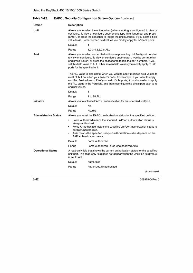
7/23/2019 Baystack 450
http://slidepdf.com/reader/full/baystack-450 202/399
3-42 309978-D Rev 01
Range 1 to 28,ALL
Initialize Allows you to activate EAPOL authentication for the specified unit/port.
Default No
Range No,Yes
Administrative Status Allows you to set the EAPOL authorization status for the specified unit/port.
• Force Authorized means the specified unit/port authorization status is
always authorized.
• Force Unauthorized means the specified unit/port authorization status isalways Unauthorized.
• Auto means the specified unit/port authorization status depends on the
EAP authentication results.
Default Force Authorized
Range Force Authorized,Force Unauthorized,Auto
Operational Status A read-only field that shows the current authorization status for the specified
unit/port. This read-only field does not appear when the Unit/Port field valueis set to ALL.
Default Authorized
Range Authorized,Unauthorized
(continued)
Using the Console Interface
Administrative Traffic
Control
Allows you to choose whether EAPOL authentication is set for incoming and
outgoing traffic or for incoming traffic only. For example, if you set the
specified unit/port field value to Incoming and Outgoing, and the EAPOL
authentication fails, then both incoming and outgoing traffic on the specified
unit/port is blocked.
Default Incoming and Outgoing
Range Incoming and Outgoing,Incoming Only
Operational Traffic
Control
A read-only field that indicates the current administrative traffic control
configuration for the specified unit/port (see preceding field description). This
read-only field does not appear when the Unit/Port field value is set to ALL.
Default Incoming and Outgoing
Range Incoming and Outgoing,Incoming Only
Re-authenticate Now Allows you to activate EAPOL authentication for the specified unit/port
immediately, without waiting for the Re-authentication Period to expire.
Default No
Range No,Yes
Re-authentication Allows you to repeat EAPOL authentication for the specified unit/port
Table 3-12. EAPOL Security Configuration Screen Options (continued)
Option Description

7/23/2019 Baystack 450
http://slidepdf.com/reader/full/baystack-450 203/399
309978-D Rev 01 3-43
according to the time interval value configured in the Re-authenticationPeriod field (see next field description).
Default Enabled
Range Enabled,Disabled
Re-authentication Period When the Re-authentication field value (see preceding field) is set to
Enabled, this field allows you to specify the time period between successive
EAPOL authentications for the specified unit/port.
Default 3600 seconds
Range 1 to 604800 seconds
Quiet Period Allows you to specify the time period between any single EAPOL
authentication failure and the start of a new EAPOL authentication attempt.
Default 60 seconds
Range 0 to 65535 seconds
Transmit Period Allows you to specify how long the switch waits for the supplicant to respondto EAP Request/Identity packets.
Default 30 seconds
Range 1 to 65535 seconds
(continued)

7/23/2019 Baystack 450
http://slidepdf.com/reader/full/baystack-450 204/399
Using the Console Interface
VLAN Configuration Menu
VLAN Configuration... VLAN Port Configuration... VLAN Display by Port...Traffic Class Configuration...Return to Switch Configuration Menu
Use arrow keys to highlight option, press <Return> or <Enter> to select option.Press Ctrl-R to return to previous menu. Press Ctrl-C to return to Main Menu.

7/23/2019 Baystack 450
http://slidepdf.com/reader/full/baystack-450 205/399
309978-D Rev 01 3-45
Figure 3-17. VLAN Configuration Menu
Table 3-13 describes the VLAN Configuration Menu options.
Table 3-13. VLAN Configuration Menu Options
Option Description
VLAN Configuration... Displays the VLAN Configuration screen (see “VLAN Configuration” on
page 3-46). This screen allows you to set up VLAN workgroups.
VLAN Port
Configuration...
Displays the VLAN Port Configuration screen (see “VLAN Port Configuration”
on page 3-52). This screen allows you to set up a specific switch port.
VLAN Display by Port... Displays the VLAN Display by Port screen (see “VLAN Display by Port” on
page 3-56).
Traffic ClassConfiguration... Displays the Traffic Class Configuration screen (see “Traffic ClassConfiguration” on page 3-57).
Return to Switch
Configuration Menu
Exits the VLAN Configuration Menu and displays the Switch Configuration
Menu.
Using the BayStack 450 10/100/1000 Series Switch
VLAN Configuration
The VLAN Configuration screen (Figure 3-18) allows you to assign VLAN port
memberships to standalone or stacked unit ports. You can also create port-basedVLANs and protocol-based VLANs:
• Port-based VLANs allow you to explicitly configure switch ports as VLAN
port members.• Protocol-based VLANs allow you to configure your switch ports as members
of a broadcast domain, based on the protocol information within a packet.
Protocol-based VLANs can localize broadcast traffic and assure that only theprotocol-based VLAN ports are flooded with the specified protocol-typepackets.
When you configure ports as VLAN port members, they become part of a set of ports that form a broadcast domain for a specific VLAN. You can assign switchports, whether standalone or stacked unit ports, as VLAN port members of one ormore VLANs.
You can assign VLAN port members attributes that allow the individual ports tooperate in accordance with the IEEE 802.1Q tagging rules. You can define each of
d d

7/23/2019 Baystack 450
http://slidepdf.com/reader/full/baystack-450 206/399
3-46 309978-D Rev 01
the VLAN port members as tagged or untagged (see “IEEE 802.1Q Tagging” onpage 1-52 for a description of important terms used with 802.1Q VLANs).
You can also use this screen to create or delete specific VLANs, assign VLANnames, and assign any VLAN as the management VLAN.
Choose VLAN Configuration (or press v) from the VLAN Configuration Menu toopen the VLAN Configuration screen.
Using the Console Interface
Figure 3 18 VLAN Configuration Screen
VLAN Configuration
Create VLAN: [ 1 ] VLAN Type: [ Port-Based ]Delete VLAN: [ ] Protocol Id (PID): [ None ]
VLAN Name: [ VLAN #1 ] User-Defined PID: [ 0x0000 ]Management VLAN: [ Yes ] VLAN State: [ Active ]
Port Membership1-6 7-12 13-18 19-24 25------ ------ ------ ------ ------
Unit #1 UUUUUU UUUUUU UUUUUU UUUUUUUnit #2 UUUUUU UUUUUU UUUUUU UUUUUU UUnit #3 UUUUUU UUUUUU UUUUUU UUUUUUUnit #4 UUUUUU UUUUUU UUUUUU UUUUUU
Enter VLAN Number: 1KEY: T = Tagged Port Member, U = Untagged Port Member, - = Not a Member of VLANUse space bar to display choices, press <Return> or <Enter> to select choice.Press Ctrl-R to return to previous menu. Press Ctrl-C to return to Main Menu.

7/23/2019 Baystack 450
http://slidepdf.com/reader/full/baystack-450 207/399
309978-D Rev 01 3-47
Figure 3-18. VLAN Configuration Screen
Table 3-14 describes the VLAN Configuration screen fields.
Table 3-14. VLAN Configuration Screen Fields
Field Description
Create VLAN Allows you to set up or view configured VLAN workgroups. Enter the number of the
new VLAN you want to create or view, and then press [Enter]. The Port Membership
fields indicate the corresponding VLAN workgroup configuration, if configured, or all
dashes (-), indicating no VLAN Members configured. Alternatively, you can use the
spacebar to toggle through the various configured VLAN workgroups. You can
create up to 64 different VLANs (including VLAN 1).
Default 1
Range 2 to 4094(continued)
Using the BayStack 450 10/100/1000 Series Switch
Delete VLAN Allows you to delete a specified VLAN, except the assigned management VLAN
(see Management VLAN field). Enter the number of the VLAN you want to delete,
and then press [Enter], or use the spacebar to toggle through the selection until you
reach the specific VLAN you want to delete, and then press [Enter].
The specified VLAN is deleted as soon as you press [Enter]. The software does not
prompt you to confirm this action. If you delete a VLAN, all configuration parameters
that are associated with that VLAN are deleted also.
You cannot delete VLAN 1. By default, all switch ports are assigned as untagged
members of VLAN 1 with all ports configured as PVID = 1. See “IEEE 802.1Q VLAN
Workgroups” on page 1-50 for more information.
Default blank field
Range 2 to 4094
VLAN Name Allows you to assign a name to configured VLANs.
Default VLAN # (VLAN number )
Range Any ASCII string of up to 16 printable characters
Management VLAN Allows you to assign any VLAN as the management VLAN. VLAN 1 is the default
management VLAN for the switch. To set this field, the VLAN State field value must
be Active and the VLAN Type field value must be Port-Based or Protocol-Based( ith th P t l Id (PID) Fi ld l t t I Eth 2)
Table 3-14. VLAN Configuration Screen Fields (continued)
Field Description

7/23/2019 Baystack 450
http://slidepdf.com/reader/full/baystack-450 208/399
3-48 309978-D Rev 01
be Active, and the VLAN Type field value must be Port-Based or Protocol-Based(with the Protocol Id (PID) Field value set to IpEther2).
Default Yes
Range Yes, No
VLAN Type Allows you to select the type of VLAN (port-based or protocol-based) to create. To
set this field, the VLAN State field value must be Inactive.
Default Port-Based
Range Port-Based, Protocol-Based
Protocol Id (PID) Allows you to set the protocol type of your protocol-based VLAN (to set this field, the
VLAN State field value must be Inactive). You can choose from any of 15 predefined
supported protocols (see “Predefined Protocol Identifier (PID) Description” on
page 3-50), or you can create your own user-defined protocol-based VLAN (see the
User-defined PID field description for more information).
Default None
Range None, Ip Ether2, Ipx 802.3, Ipx 802.2, Ipx Snap, Ipx Ether2, AplTk Ether2Snap, Declat Ether2, DecOth Ether2, Sna 802.2,
Sna Ether2, NetBios 802.2, Xns Ether2, Vines Ether2, Ipv6 Ether2, User-Defined, Rarp Ether2
(continued)
Using the Console Interface
User-Defined PID Allows you to create your own user-defined protocol-based VLAN where you specify
the Protocol Identifier (PID) for the VLAN. To set this field, the VLAN State field must
be set to Inactive (some restrictions apply, see “User-Defined Protocol Identifier
(PID) Description” on page 3-51).
Default 0x0000
Range Any 4-bit hexadecimal value (for example, 0xABCD)
VLAN State Allows you to activate your newly created VLAN.
• The following associated field values: VLAN Type, Protocol Id (PID), and
User-Defined PID must be configured appropriately before this field can be set
to Active.
• After you set the VLAN State field value to Active, you cannot change the VLAN
Type, Protocol Id, or User-defined PID field values, unless you delete the VLAN.
• If you delete a VLAN, all configuration parameters that are associated with that
VLAN are deleted also.
Default Inactive (for all VLANs except VLAN 1)
Range Inactive, Active
Port Membership Allows you to assign VLAN port memberships to standalone or stacked unit ports.
The ports can be configured in one or more VLANs. To set this field, you must set
the VLAN State field value to Active
Table 3-14. VLAN Configuration Screen Fields (continued)
Field Description

7/23/2019 Baystack 450
http://slidepdf.com/reader/full/baystack-450 209/399
309978-D Rev 01 3-49
the VLAN State field value to Active.
Certain restrictions apply for gigabit ports and when using the BayStack 410-24T
switch ports as participants of protocol-based VLANs (see “Gigabit Ports and
BayStack 410-24T Switch Ports Restriction” on page 3-52).
This field depends on the Tagging field value in the VLAN Port Configuration screen.
For example:
• When the Tagging field is set to Untagged Access , you can set the PortMembership field as an untagged port member (U) or as a non-VLAN port
member (-).
• When the Tagging field is set to Tagged Trunk , you can set the Port Membership
field as a tagged port member (T) or as a non-VLAN port member (-).
(see the Tagging field description in Table 3-17 on page 3-53).
The Port Membership fields are displayed in six-port groups (for example, 1-6, 7-12,
13-18). The number of ports displayed depends on the switch model or type ofoptional MDA installed in the Uplink Module slot.
Default U (All ports are assigned as untagged members of VLAN 1.)
Range U, T, and -

7/23/2019 Baystack 450
http://slidepdf.com/reader/full/baystack-450 210/399

7/23/2019 Baystack 450
http://slidepdf.com/reader/full/baystack-450 211/399

7/23/2019 Baystack 450
http://slidepdf.com/reader/full/baystack-450 212/399

7/23/2019 Baystack 450
http://slidepdf.com/reader/full/baystack-450 213/399

7/23/2019 Baystack 450
http://slidepdf.com/reader/full/baystack-450 214/399
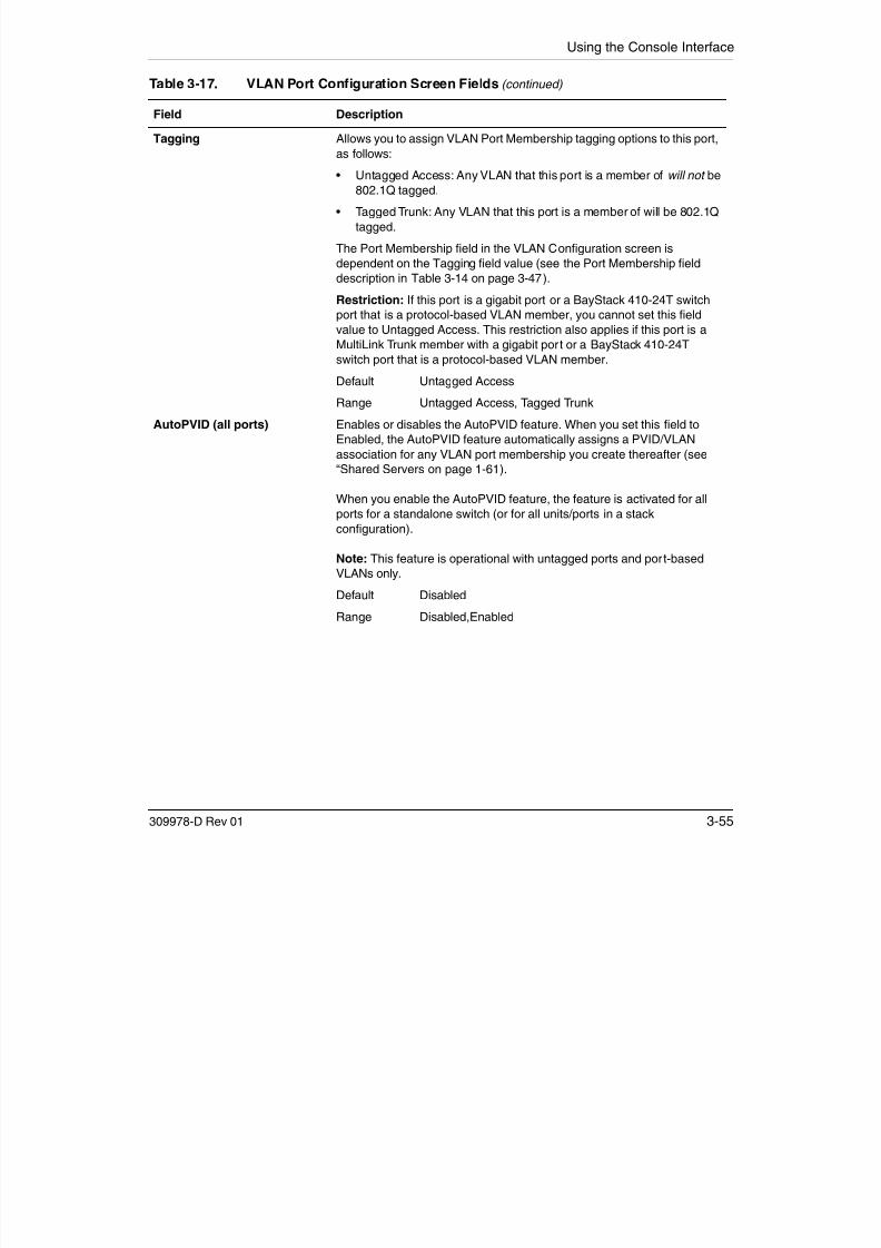
7/23/2019 Baystack 450
http://slidepdf.com/reader/full/baystack-450 215/399

7/23/2019 Baystack 450
http://slidepdf.com/reader/full/baystack-450 216/399
Using the Console Interface
Traffic Class Configuration
The Traffic Class Configuration screen (Figure 3-21) allows you to assign a Lowor High traffic classification to any of eight (0 to 7) user_priority values assigned
Table 3-18. VLAN Display by Port Screen Fields
Field Description
Unit Allows you to select the unit number (when stacking is configured) to view. To
view another unit, type its unit number and press [Enter], or press the
spacebar to toggle the unit numbers.
Port Allows you to select the number of the port you want to view. To view another
port, type its port number and press [Enter], or press the spacebar on your
keyboard to toggle the port numbers.
PVID Read-only field that indicates the PVID setting for the specified port.
Port Name Read-only field that indicates the port name assigned to the specified port.
VLANs Column header for the read-only fields listing the VLANs associated with thespecified port.
VLAN Name Column header for the read-only fields listing the VLAN Names associated
with the specified port.

7/23/2019 Baystack 450
http://slidepdf.com/reader/full/baystack-450 217/399
309978-D Rev 01 3-57
to a received frame on specified switch ports.
See “IEEE 802.1p Prioritizing” on page 1-74 for more information about thisscreen.
Choose Traffic Class Configuration (or press t) from the VLAN ConfigurationMenu to open the Traffic Class Configuration screen.
Note: If you change the Traffic Class Configuration for any switch in a stackconfiguration, the entire stack resets with the current configuration settings(see Table 3-1 on page 3-6 for details of the Reset option).
Using the BayStack 450 10/100/1000 Series Switch
Figure 3-21. Traffic Class Configuration Screen
Traffic Class Configuration
User Priority Traffic Class------------- -------------
Priority 0: [ Low ]Priority 1: [ Low ]Priority 2: [ Low ]Priority 3: [ Low ]Priority 4: [ Low ]Priority 5: [ Low ]Priority 6: [ Low ]Priority 7: [ Low ]
Changing the priorities of the traffic classes will cause an automaticReset to Current Settings to occur across the entire stack.The current configuration will be adapted to the new set of priorities
Are you sure you want to change priorities to the new settings? [ No ]
Use space bar to display choices, press <Return> or <Enter> to select choice.Press Ctrl-R to return to previous menu. Press Ctrl-C to return to Main Menu.

7/23/2019 Baystack 450
http://slidepdf.com/reader/full/baystack-450 218/399
3-58 309978-D Rev 01
Table 3-19 describes the Traffic Class Configuration screen fields.
Table 3-19. Traffic Class Configuration Screen Fields
Field Description
User Priority Column header for the read-only fields that indicate the user priority values
from 0 to 7. These values are derived from the 3-bit field in the header of
802.1Q tagged frames (see “IEEE 802.1Q Tagging” on page 1-52).
Traffic Class Column header for the eight user-configurable fields that correspond to the
adjacent user priority levels.
Default Low
Range Low, High
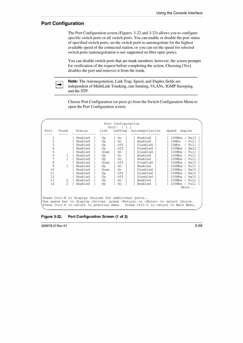
7/23/2019 Baystack 450
http://slidepdf.com/reader/full/baystack-450 219/399

7/23/2019 Baystack 450
http://slidepdf.com/reader/full/baystack-450 220/399
Using the Console Interface
Table 3-20. Port Configuration Screen Fields
Field Description
Unit Allows you to select the unit number (when stacking is configured) to view or
configure. To view or configure another unit, type its unit number and press [Enter], or
press the spacebar to toggle the unit numbers.
Port Indicates the switch port numbers that correspond to the field values in that row of
the screen (for example, the field values in row 2 apply to switch port 2). The values
that you set in the Switch row will affect all switch ports and, when the switch is part
of a stack, the values that you set in the Stack row will affect all ports in the entire
stack (except the gigabit MDA ports or fiber optic ports, when installed).
Trunk The read-only data displayed in this column indicates the trunks that correspond to
the switch ports specified in the Trunk Members fields of the Trunk Configurationscreen (see “MultiLink Trunk Configuration” on page 3-64).
Status Allows you to disable any of the switch ports. You can also use this field to control
access to any switch port.
Default Enabled
Range Enabled, Disabled
Link A read-only field that indicates the current link state of the corresponding port, as
follows:• Up: The port is connected and operational.
• Down: The port is not connected or is not operational.

7/23/2019 Baystack 450
http://slidepdf.com/reader/full/baystack-450 221/399
309978-D Rev 01 3-61
Down: The port is not connected or is not operational.
LnkTrap Allows you to control whether link up/link down traps are sent to the configured trap
sink from the switch.
Default On
Range On, Off
Autonegotiation When enabled, sets the corresponding port speed to match the best service providedby the connected station, up to 100 Mb/s in full-duplex mode. This field is disabled for
all fiber optic ports.
Default Enabled
Range Enabled, Disabled
Speed/Duplex1
1 Fiber optic ports can only be set to 100Mbs/Half or 100Mbs/Full.
Allows you to manually configure any port to support an Ethernet speed of 10 Mb/s or
100 Mb/s, in half- or full-duplex mode. This field is set (by default) to 1000 Mb/s,
full-duplex for gigabit ports only.Default 100Mbs/Half (when Autonegotiation is Disabled)
Range 10Mbs/Half, 10Mbs/Full, 100Mbs/Half, 100Mbs/Full
Using the BayStack 450 10/100/1000 Series Switch
High Speed Flow Control Configuration
The High Speed Flow Control Configuration screen (Figure 3-24) allows you toset the port parameters for installed gigabit MDAs.
Choose High Speed Flow Control Configuration (or press h) from the SwitchConfiguration Menu to open the High Speed Flow Control Configuration screen.
Note: This screen appears only when an optional gigabit MDA is installed in
the Uplink Module slot.
High Speed Flow Control Configuration
Unit: [ 1 ]
Autonegotiation: [ Enabled ]Flow Control: DisabledPreferred Phy: [ Right ]
Active Phy: Right

7/23/2019 Baystack 450
http://slidepdf.com/reader/full/baystack-450 222/399
3-62 309978-D Rev 01
Figure 3-24. High Speed Flow Control Configuration Screen
Table 3-21 describes the High Speed Flow Control Configuration screen fields.
Use space bar to display choices, press <Return> or <Enter> to select choice.Press Ctrl-R to return to previous menu. Press Ctrl-C to return to Main Menu.
Using the Console Interface
Table 3-21. High Speed Flow Control Configuration Screen Fields
Field Description
Unit Allows you to select the unit number (when stacking is configured) to view or
configure. To view or configure another unit, type its unit number and press
[Enter], or press the spacebar to toggle the unit numbers (the system displays ascreen only for units that are configured with a gigabit MDA).
Autonegotiation When enabled, the port advertises support only for 1000 Mb/s operation, in
full-duplex mode.
Default Enabled
Range Enabled, Disabled
Flow Control Allows you to control traffic and avoid congestion on the gigabit MDA port. Two
modes are available (see “Choosing a High Speed Flow Control Mode” on
page 3-63 for details about the two modes). The Flow Control field cannot be
configured unless you set the Autonegotiation field value to Disabled.
Default Disabled
Range Disabled, Symmetric, Asymmetric
Note: The following two fields appear only when a (single MAC) MDA with aseparate redundant Phy port is installed.
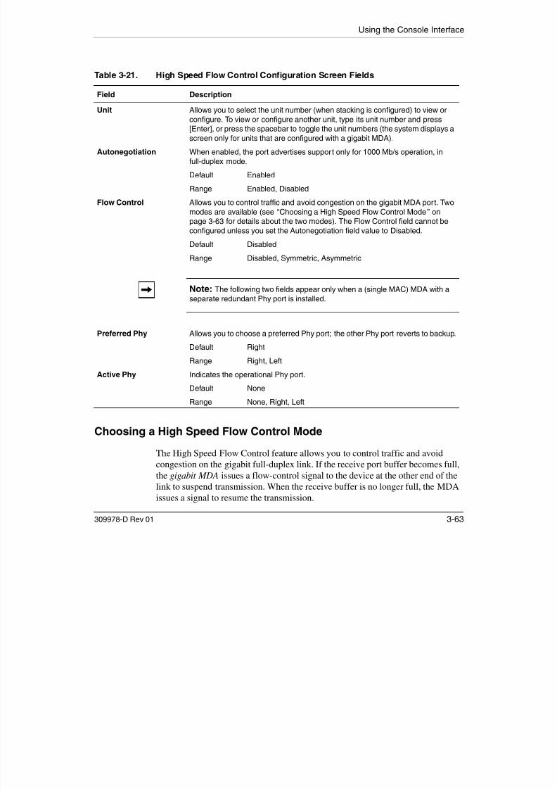
7/23/2019 Baystack 450
http://slidepdf.com/reader/full/baystack-450 223/399
309978-D Rev 01 3-63
Choosing a High Speed Flow Control Mode
The High Speed Flow Control feature allows you to control traffic and avoidcongestion on the gigabit full-duplex link. If the receive port buffer becomes full,the gigabit MDA issues a flow-control signal to the device at the other end of thelink to suspend transmission. When the receive buffer is no longer full, the MDAissues a signal to resume the transmission.
Preferred Phy Allows you to choose a preferred Phy port; the other Phy port reverts to backup.
Default Right
Range Right, Left
Active Phy Indicates the operational Phy port.
Default None
Range None, Right, Left
Using the BayStack 450 10/100/1000 Series Switch
You can choose Symmetric or Asymmetric flow control mode.
Symmetric Mode
This mode allows both the gigabit MDA port and its link partner to send flowcontrol pause frames to each other.
When a pause frame is received (by either the gigabit MDA port or its linkpartner), the port suspends transmission of frames for a number of slot timesspecified in the control frame or until a pause-release control frame is received.Both devices on the link must support this mode when it is selected.
Asymmetric Mode
This mode allows the link partner to send flow control pause frames to the gigabitMDA port. When a pause frame is received, the receiving port suspendstransmission of frames for a number of slot times specified in the control frame oruntil a pause-release control frame is received.
In this mode the gigabit MDA port is disabled from transmitting pause frames toits link partner. Use this mode when the gigabit MDA port is connected to abuffered repeater device.
MultiLink Trunk Configuration

7/23/2019 Baystack 450
http://slidepdf.com/reader/full/baystack-450 224/399
3-64 309978-D Rev 01
The MultiLink Trunk Configuration Menu (Figure 3-25) allows you to select theappropriate screen to configure up to six MultiLink trunks (you can group up tofour switch ports to form each trunk).
You can configure up to six MultiLink trunks in each stack, with trunk members ineither a single unit or distributed between units within the stack configuration(distributed trunking).
You can monitor the bandwidth usage for the trunk member ports within eachtrunk. For more information about configuring MultiLink Trunks, see “MultiLinkTrunks” on page 1-78.
Note: When a trunk is not active (Trunk Status field set to Disabled),configuration changes do not take effect until you set the Trunk Status field toEnabled.
Using the Console Interface
Choose MultiLink Trunk Configuration (or press t) from the Switch ConfigurationMenu to open the MultiLink Trunk Configuration Menu.
Figure 3-25. MultiLink Trunk Configuration Menu
MultiLink Trunk Configuration Menu
MultiLink Trunk Configuration...MultiLink Trunk Utilization...Return to Switch Configuration Menu
Use arrow keys to highlight option, press <Return> or <Enter> to select option.Press Ctrl-R to return to previous menu. Press Ctrl-C to return to Main Menu.
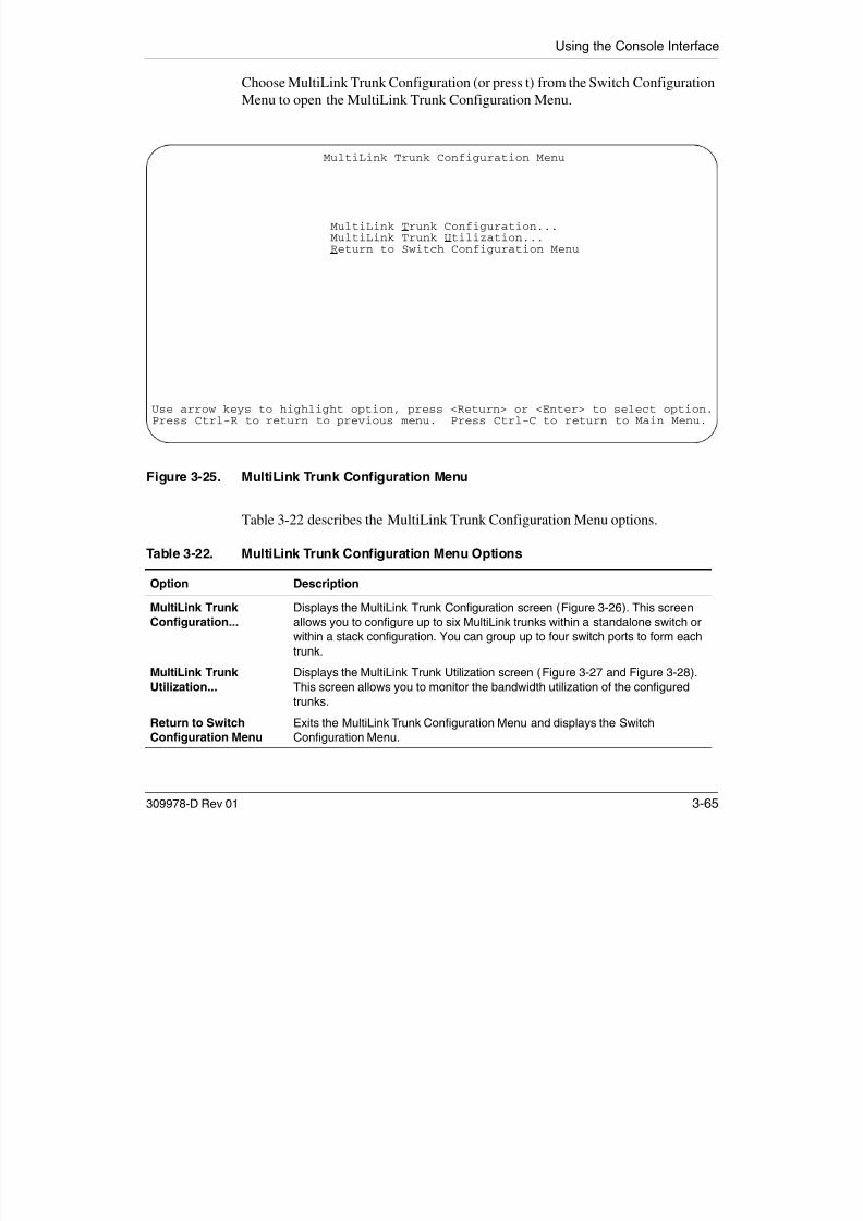
7/23/2019 Baystack 450
http://slidepdf.com/reader/full/baystack-450 225/399
309978-D Rev 01 3-65
Table 3-22 describes the MultiLink Trunk Configuration Menu options.
Table 3-22. MultiLink Trunk Configuration Menu Options
Option Description
MultiLink Trunk
Configuration...
Displays the MultiLink Trunk Configuration screen (Figure 3-26). This screen
allows you to configure up to six MultiLink trunks within a standalone switch or
within a stack configuration. You can group up to four switch ports to form each
trunk.
MultiLink Trunk
Utilization...
Displays the MultiLink Trunk Utilization screen (Figure 3-27 and Figure 3-28).
This screen allows you to monitor the bandwidth utilization of the configured
trunks.
Return to SwitchConfiguration Menu
Exits the MultiLink Trunk Configuration Menu and displays the Switch
Configuration Menu.

7/23/2019 Baystack 450
http://slidepdf.com/reader/full/baystack-450 226/399

7/23/2019 Baystack 450
http://slidepdf.com/reader/full/baystack-450 227/399

7/23/2019 Baystack 450
http://slidepdf.com/reader/full/baystack-450 228/399
Using the Console Interface
Figure 3-27. MultiLink Trunk Utilization Screen (1 of 2)
MultiLink Trunk Utilization
Trunk Traffic Type Unit/Port Last 5 Minutes Last 30 Minutes Last Hour----- ------------- --------- -------------- --------------- ---------1 [ Rx and Tx ] 3/6 90.0% 70.0% 90.0%
3/7 20.0% 55.0% 80.0%3/9 35.0% 45.0% 45.0%
3/17 85.0% 35.0% 20.0%2 [ Rx and Tx ] 4/25 45.0% 45.0% 50.0%4/26 25.0% 70.0% 35.0%
3 [ Rx and Tx ] 6/13 35.0% 35.0% 50.0%6/14 30.0% 80.0% 70.0%
4 [ Rx and Tx ] 5/19 40.0% 35.0% 75.0%5/20 25.0% 70.0% 85 0%
More...Press Ctrl-N to display utilization for trunks 5-6.Use space bar to display choices, press <Return> or <Enter> to select choice.Press Ctrl-R to return to previous menu. Press Ctrl-C to return to Main Menu.

7/23/2019 Baystack 450
http://slidepdf.com/reader/full/baystack-450 229/399
309978-D Rev 01 3-69

7/23/2019 Baystack 450
http://slidepdf.com/reader/full/baystack-450 230/399
Using the Console Interface
Port Mirroring Configuration
The Port Mirroring Configuration screen allows you to configure a specific switchport to monitor up to two specified ports or two MAC addresses. You can specifyport-based monitoring or address-based monitoring. In a stack configuration, youcan monitor ports that reside on different units within the stack.
For more information about the port mirroring feature, see “Port Mirroring(Conversation Steering)” on page 1-97.
Figure 3-29 shows an example of a Port Mirroring Configuration screen, in a stackconfiguration, where port 12 (in stack unit 3) is designated as the monitoring port
Last 5 Minutes This read-only field indicates the percentage of packets (of the type specified in the
Traffic Type field) the port used in the last 5 minutes. This field provides a running
average of network activity and is updated every 15 seconds.
Last 30 Minutes This read-only field indicates the percentage of packets (of the type specified in the
Traffic Type field) the port used in the last 30 minutes. This field provides a runningaverage of network activity and is updated every 15 seconds.
Last Hour This read-only field indicates the percentage of packets (of the type specified in the
Traffic Type field) the port used in the last 60 minutes. This field provides a running
average of network activity and is updated every 15 seconds.
Table 3-24. MultiLink Trunk Utilization Screen Fields (continued)
Field Description
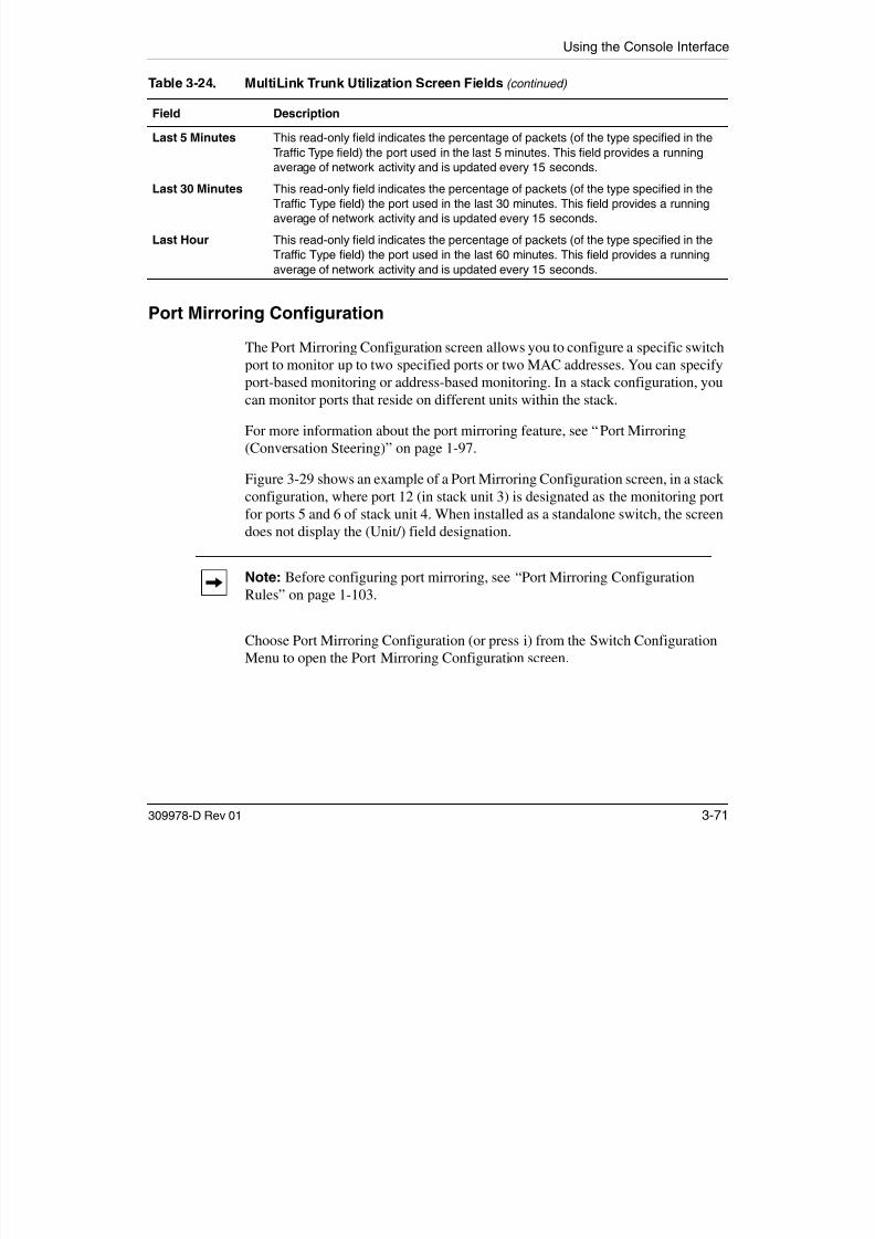
7/23/2019 Baystack 450
http://slidepdf.com/reader/full/baystack-450 231/399
309978-D Rev 01 3-71
for ports 5 and 6 of stack unit 4. When installed as a standalone switch, the screendoes not display the (Unit/) field designation.
Choose Port Mirroring Configuration (or press i) from the Switch ConfigurationMenu to open the Port Mirroring Configuration screen.
Note: Before configuring port mirroring, see “Port Mirroring ConfigurationRules” on page 1-103.

7/23/2019 Baystack 450
http://slidepdf.com/reader/full/baystack-450 232/399
Using the Console Interface
Table 3-25 describes the Port Mirroring Configuration screen fields.
Table 3-25. Port Mirroring Configuration Screen Fields
Field Description
Monitoring Mode Allows you to select any one of six port-based monitoring modes or any one of five
address-based monitoring modes (see Table 3-26). Selecting any one of the six
port-based modes activates the port X and por t Y screen fields, where you canchoose up to two ports to monitor. Selecting any one of the five address-based
modes activates the Address A and Address B screen fields, where you can specify
MAC addresses to monitor.
Default Disabled
Range See Table 3-26
Monitor Unit/Port Indicates the port number (of the specified unit) that is designated as the monitor
port.Default Zero-length string
Range 1 to 8 / 1 to 28 (depending on model type)
Unit/Port X Indicates one of the ports (of the specified unit) that will be monitored by the
designated port monitor when one of the port-based monitoring modes is selected.
This port will be monitored according to the value of Port X in the Monitoring Mode
field (see Table 3-26).
Default Zero-length string
Range 1 to 8 / 1 to 28 (depending on model type)
Unit/Port Y Indicates one of the ports (of the specified unit) that will be monitored by the

7/23/2019 Baystack 450
http://slidepdf.com/reader/full/baystack-450 233/399
309978-D Rev 01 3-73
designated port monitor when one of the port-based monitoring modes is selected.
When installed as a standalone switch, the screen does not display the (Unit/) field
designation. This port will be monitored according to the value of Port Y in the
Monitoring Mode field (see Table 3-26).
Default Zero-length stringRange 1 to 8 / 1 to 28 (depending on model type)
Address A Indicates the MAC addresses that will be monitored by the designated port monitor
when one of the address-based monitoring modes is selected. This port will be
monitored according to the value of Address A in the selected Monitoring Mode field
(see Table 3-26). Users can enter the MAC address from this screen or from the MAC
Address Table screen. The entry is displayed and can be modified by either screen
(see “MAC Address Table” on page 3-22).
Default 00-00-00-00-00-00 (no MAC address assigned)
Range 00-00-00-00-00-00 to FF-FF-FF-FF-FF-FF
(continued)
Using the BayStack 450 10/100/1000 Series Switch
Table 3-26 describes the various monitoring modes available from the PortMirroring Configuration screen.
Address B Indicates the MAC addresses that will be monitored by the designated port monitor
when one of the address-based monitoring modes is selected. This port will be
monitored according to the value of Address B in the selected Monitoring Mode field
(see Table 3-26). Users can enter the MAC address from this screen or from the MAC
Address Table screen. The entry is displayed and can be modified by either screen(see “MAC Address Table” on page 3-22).
Default 00-00-00-00-00-00 (no MAC address assigned)
Range 00-00-00-00-00-00 to FF-FF-FF-FF-FF-FF
Table 3-26. Monitoring Modes
Fields Description
Port-based:
Disabled Default value for this feature.
-> Port X Monitor all traffic Port X receives.
Port X -> Monitor all traffic Port X transmits.
<-> Port X Monitor all traffic Port X receives and transmits.
> Port X or Port Y > Monitor all traffic Port X receives or Port Y transmits
Table 3-25. Port Mirroring Configuration Screen Fields (continued)
Field Description

7/23/2019 Baystack 450
http://slidepdf.com/reader/full/baystack-450 234/399
3-74 309978-D Rev 01
-> Port X or Port Y -> Monitor all traffic Port X receives or Port Y transmits.
-> Port X and Port Y -> Monitor all traffic Port X receives (destined to Port Y), and then Port Y
transmits.
<-> Port X and Port Y <-> Monitor all traffic Port X receives/transmits and Port Y receives/transmits.
Address-based:
Disabled Default value for this feature.
Address A -> any Address Monitor all traffic Address A transmits to any address.
any Address -> Address A Monitor all traffic Address A receives from any address.
<-> Address A Monitor all traffic Address A receives or transmits.
Address A -> Address B Monitor all traffic Address A transmits to Address B.
Address A <-> Address B Monitor all traffic between Address A and Address B (conversation
between the two stations).
Using the Console Interface
Rate Limiting Configuration
The Rate Limiting Configuration screen allows you to limit the forwarding rate of broadcast and IP multicast packets.
Figures 3-30 and 3-31 show sample rate-limiting values for the two Rate LimitingConfiguration screens.
Choose Rate Limiting Configuration (or press l) from the Switch Configuration
Menu to open the Rate Limiting Configuration screen.
Note: If a port is configured for rate limiting, and it is a MultiLink trunkmember, all trunk member ports implement rate limiting. Also, if a trunkmember is implementing rate limiting and the port is disabled from ratelimiting, all trunk members are disabled from rate limiting.
Rate Limiting ConfigurationUnit: [ 1 ]
Port Packet Type Limit Last 5 Minutes Last Hour Last 24 Hours---- ------------- -------- -------------- --------- -------------
1 [ Both ] [ None ] 56.0% 22.0% 23.0%2 [ Multicast ] [ 9% ] 30.0% 27.0% 55.0%3 [ Both ] [ None ] 25.0% 24.0% 67.0%4 [ Both ] [ 10% ] 72.0% 33.0% 55.0%5 [ Broadcast ] [ 10% ] 35.0% 54.0% 78.0%6 [ l i ] [ 10% ] 96 0% 45 0% 87 0%

7/23/2019 Baystack 450
http://slidepdf.com/reader/full/baystack-450 235/399
309978-D Rev 01 3-75
Figure 3-30. Rate Limiting Configuration Screen (1 of 2)
6 [ Multicast ] [ 10% ] 96.0% 45.0% 87.0%7 [ Both ] [ 10% ] 86.0% 67.0% 60.0%8 [ Both ] [ 5% ] 58.0% 44.0% 70.0%9 [ Multicast ] [ None ] 11.0% 87.0% 65.0%10 [ Both ] [ None ] 27.0% 89.0% 44.0%11 [ Both ] [ None ] 15.0% 66.0% 66.0%12 [ Both ] [ None ] 12.0% 98.0% 99.0%13 [ Both ] [ None ] 44.0% 33.0% 89.0%14 [ Both ] [ None ] 34.0% 45.0% 76.0%
More...
Press Ctrl-N to display choices for additional ports..Use space bar to display choices, press <Return> or <Enter> to select choice.Press Ctrl-R to return to previous menu. Press Ctrl-C to return to Main Menu.
Using the BayStack 450 10/100/1000 Series Switch
Figure 3-31. Rate Limiting Configuration Screen (2 of 2)
You can use this screen to view the percentage of either packet type (or both
Rate Limiting ConfigurationUnit: [ 1 ]
Port Packet Type Limit Last 5 Minutes Last Hour Last 24 Hours---- ------------- -------- -------------- --------- -------------15 [ Both ] [ None ] 44.0% 56.0% 0.0%16 [ Both ] [ None ] 67.0% 34.0% 0.0%
17 [ Multicast ] [ 10% ] 65.0% 48.0% 45.0%18 [ Both ] [ None ] 77.0% 74.0% 60.0%19 [ Both ] [ 10% ] 80.0% 89.0% 90.0%20 [ Both ] [ None ] 78.0% 83.0% 98.0%21 [ Broadcast ] [ None ] 98.0% 88.0% 44.0%22 [ Both ] [ None ] 34.0% 93.0% 0.0%23 [ Both ] [ None ] 65.0% 82.0% 56.0%24 [ Multicast ] [ None ] 76.0% 65.0% 50.0%25 [ Both ] [ 5% ] 88.0% 67.0% 0.0%26 [ Both ] [ None ] 35.0% 45.0% 90.0%27 [ Both ] [ None ] 25.0% 48.0% 78.0%28 [ Both ] [ None ] 17.0% 77.0% 89.0%Switch[ Both ] [ None ]Stack [ Both ] [ None ]
Press Ctrl-P to display choices for ports 1-14.Use space bar to display choices, press <Return> or <Enter> to select choice.Press Ctrl-R to return to previous menu. Press Ctrl-C to return to Main Menu.
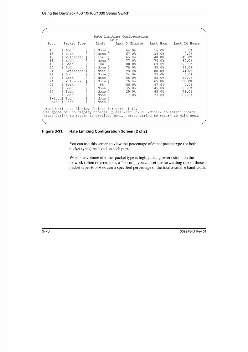
7/23/2019 Baystack 450
http://slidepdf.com/reader/full/baystack-450 236/399
3-76 309978-D Rev 01
packet types) received on each port.
When the volume of either packet type is high, placing severe strain on thenetwork (often referred to as a “storm”), you can set the forwarding rate of those
packet types to not exceed a specified percentage of the total available bandwidth.
Using the Console Interface
Table 3-27 describes the Rate Limiting Configuration screen fields.
Table 3-27. Rate Limiting Configuration Screen Fields
Field Description
Unit Appears only if the switch is participating in a stack configuration. The field allows
you to select the number of the unit you want to view or configure. To view or
configure another unit, type its unit number and press [Enter], or press thespacebar on your keyboard to toggle the unit numbers.
Port Indicates the switch port numbers that correspond to the field values in that row of
the screen (for example, the field values in row 2 apply to switch port 2). Note that
the values applied in the Switch or Stack row (last 2 rows) affect all standalone
switch ports or all switch ports in a stack.
Packet Type Allows you to select the packet types for rate limiting or viewing.
Default BothRange Both, Multicast, Broadcast
Limit Sets the percentage of port bandwidth allowed for forwarding the packet types
specified in the Packet Type field. When the threshold is exceeded, any additional
packets (specified in the Packet Type field) are discarded1.
Default None
Range None, 10%, 9%, 8%, 7%, 6%, 5%, 4%, 3%, 2%, 1%
Last 5 Minutes This read-only field indicates the percentage of packets (of the type specified in
the Packet Type field) the port received in the last 5 minutes. This field provides a
running average of network activity and is updated every 15 seconds.
N h hi fi ld i di h i i ’ i f k i i

7/23/2019 Baystack 450
http://slidepdf.com/reader/full/baystack-450 237/399
309978-D Rev 01 3-77
1 Rate limiting is disabled if this field is set to None. This allows you to select and view the percentage of specific packet
types present in the network, without inadvertently limiting the forwarding rate.
Note that this field indicates the receiving port’s view of network activity,
regardless of the rate-limiting setting.
Last Hour This read-only field indicates the percentage of packets (of the type specified in
the Packet Type field) the port received in the last 60 minutes. This field provides a
running average of network activity and is updated every 5 minutes.
Note that this field indicates the receiving port’s view of network activity,
regardless of the rate-limiting setting.
Last 24 Hours This read-only field indicates the percentage of packets (of the type specified in
the Packet Type field) the port received in the last 24 hours. This field provides a
running average of network activity and is updated every hour.
Note that this field indicates the receiving port’s view of network activity,regardless of the rate-limiting setting.
Using the BayStack 450 10/100/1000 Series Switch
IGMP Configuration Menu
The IGMP Configuration Menu (Figure 3-32) allows you to select the appropriatescreen to optimize IP multicast packets in a bridged Ethernet environment (see“IGMP Snooping” on page 1-69).
Choose IGMP Configuration (or press g) from the Switch Configuration Menu to
open the IGMP Configuration Menu.
IGMP Configuration Menu
IGMP Configuration...Display Multicast Group Membership...Return to Switch Configuration Menu

7/23/2019 Baystack 450
http://slidepdf.com/reader/full/baystack-450 238/399
3-78 309978-D Rev 01
Figure 3-32. IGMP Configuration Menu
Table 3-28 describes the IGMP Configuration Menu options.
Use arrow keys to highlight option, press <Return> or <Enter> to select option.Press Ctrl-R to return to previous menu. Press Ctrl-C to return to Main Menu.
Using the Console Interface
IGMP Configuration
Figure 3-33 shows an example of the IGMP Configuration screen in a stackedconfiguration (when installed as a standalone switch, the screen does not displaythe Unit # field designation).
Switch ports 8 and 14 of unit 1, ports 2 and 6 of unit 2, and port 16 of unit 4 areconfigured to receive all IP multicast-related traffic. The configured ports areVLAN port members of VLAN 5, and are called Static Router Ports.
Table 3-28. IGMP Configuration Menu Options
Option Description
IGMP Configuration... Displays the IGMP Configuration screen (see “IGMP Configuration” following
this table). This screen allows you to set up IGMP configurations.
Display Multicast Group
Membership...
Displays the Multicast Group Membership screen (see “Multicast Group
Membership” on page 3-83). This screen allows you to view all IP multicast
addresses that are active in the current LAN.
Return to SwitchConfiguration Menu
Exits the IGMP Configuration Menu and displays the Switch Configuration
Menu.
Note: Before configuring your switch for IGMP snooping, see “IGMPSnooping Configuration Rules” on page 1-73.

7/23/2019 Baystack 450
http://slidepdf.com/reader/full/baystack-450 239/399
309978-D Rev 01 3-79
Choose IGMP Configuration (or press g) from the IGMP Configuration Menu toopen the IGMP Configuration screen.

7/23/2019 Baystack 450
http://slidepdf.com/reader/full/baystack-450 240/399
Using the Console Interface
Proxy Allows the switch to consolidate IGMP Host Membership Reports received on its
downstream ports and to generate a consolidated proxy report for forwarding to its
upstream neighbor.
This field affects all VLANs (for example, if you disable Proxy for the VLAN specified
in the screen’s VLAN field, Proxy is disabled for ALL VLANs). You cannot set the
Proxy field value to Disabled unless the Snooping field value is Enabled.
Default Enabled
Range Enabled, Disabled
Robust Value Allows you to set the switch to offset expected packet loss on a subnet. If packet
losses on a subnet are unacceptably high, the Robust Value field can be increased
to a higher value.
This field affects only the VLAN specified in the screen’s VLAN field (for example, if
you change the robust value on the VLAN specified in the screen’s VLAN field, other
VLANs are not affected).
Default 2
Range 1 to 64
Query Time Allows you to control the number of IGMP messages allowed on the subnet by
varying the Query Interval (the Query Interval is the interval between generalqueries sent by the IP multicast router).
This field affects only the VLAN specified in the screen’s VLAN field (for example, if
you change the Query Time value field on the VLAN specified in the screen’s VLAN
Table 3-29. IGMP Configuration Screen Fields (continued)
Field Description

7/23/2019 Baystack 450
http://slidepdf.com/reader/full/baystack-450 241/399
309978-D Rev 01 3-81
field, other VLANs are not affected).
Default 125 seconds
Range 1 to 512 seconds
Set Router Ports Selects the IGMP version according to the IGMPv1 (Version 1) or IGMPv2
(Version 2) standard (see RFC 2236).
Use this field in conjunction with the Static Router Ports field (see next field
description) to select the IGMP version to set. You can also use this field to view
which Static Router Ports are set to Version 1 or to Version 2. Use the spacebar to
toggle between the two versions and view the Static Router Ports settings. This field
affects all VLANs (for example, if you change the value of the Set Router Ports field
on the VLAN specified in the screen’s VLAN field, all VLANs are affected).Default Version 1
Range Version 1, Version 2
(continued)
7/23/2019 Baystack 450
http://slidepdf.com/reader/full/baystack-450 242/399
Using the Console Interface
Multicast Group Membership
The Multicast Group Membership screen allows you to view configured IPmulticast group addresses for specific VLANs. The screen displays the IPmulticast group addresses associated with ports that are configured within astandalone switch or a stack of switches.
The displayed addresses are dynamic, and can change as clients join or leave thevarious IP multicast groups. You can view changes by refreshing the screen (press[Ctrl]-P to refresh the screen).
Choose Display Multicast Group Membership (or press d) from the IGMPConfiguration Menu to open the Multicast Group Membership screen.
Note: The Multicast Group Membership screen will not display any entries if the Snooping field value is set to Disabled in the IGMP Configuration screen(see “IGMP Configuration” on page 3-79).

7/23/2019 Baystack 450
http://slidepdf.com/reader/full/baystack-450 243/399
309978-D Rev 01 3-83

7/23/2019 Baystack 450
http://slidepdf.com/reader/full/baystack-450 244/399
Using the Console Interface
Port Statistics
The Port Statistics screen (Figure 3-35) allows you to view detailed informationabout any switch port in a stacked or standalone configuration. The screen isdivided into two sections (Received and Transmitted) so that you can compare andevaluate throughput or other port parameters. All screen data is updatedapproximately every two seconds.
You can use the Port Statistics screen to clear (reset to zero) port counters for aspecific port. Alternatively, you can use the Clear All Port Statistics option to clearport counters for all ports (see “Switch Configuration” on page 3-19).
Choose Display Port Statistics (or press d) from the Switch Configuration Menuto open the Port Statistics screen.
Port StatisticsUnit: [ 1 ] Port: [ 1 ]
Received Transmitted-------------------------------------- --------------------------------------Packets: 0 Packets: 0Multicasts: 0 Multicasts: 0Broadcasts: 0 Broadcasts: 0Total Octets: 0 Total Octets: 0Lost Packets: 0 Lost Packets: 0Packets 64 bytes: 0 Packets 64 bytes: 0
65-127 bytes 0 65-127 bytes 0128-255 bytes 0 128-255 bytes 0256-511 bytes 0 256-511 bytes 0512-1023 bytes 0 512-1023 bytes 0
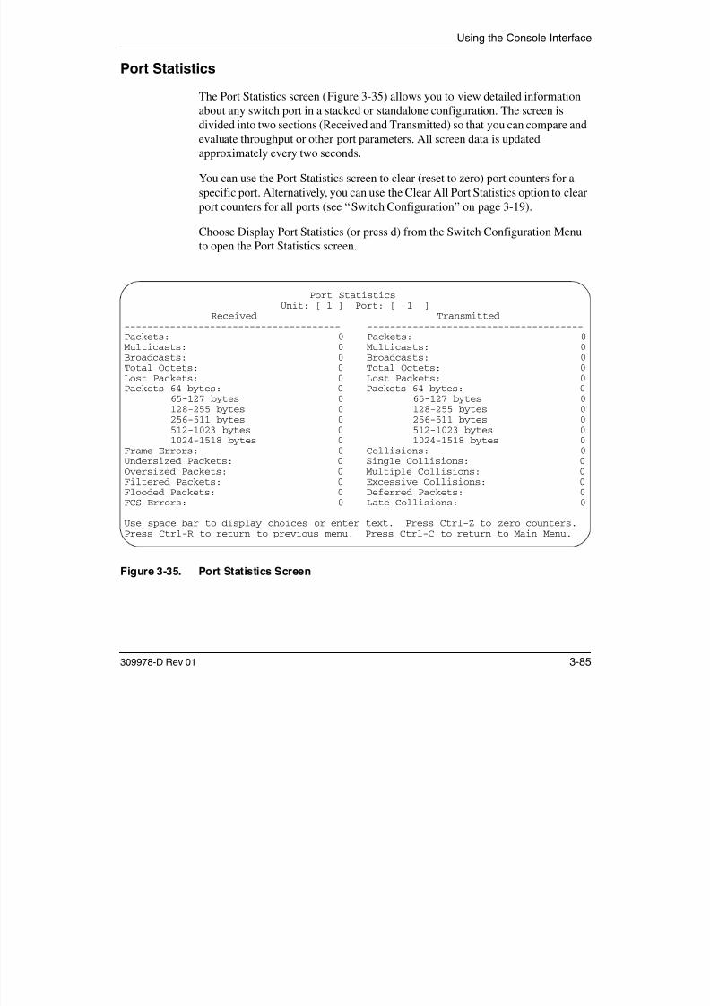
7/23/2019 Baystack 450
http://slidepdf.com/reader/full/baystack-450 245/399
309978-D Rev 01 3-85
Figure 3-35. Port Statistics Screen
1024-1518 bytes 0 1024-1518 bytes 0Frame Errors: 0 Collisions: 0Undersized Packets: 0 Single Collisions: 0Oversized Packets: 0 Multiple Collisions: 0Filtered Packets: 0 Excessive Collisions: 0Flooded Packets: 0 Deferred Packets: 0FCS Errors: 0 Late Collisions: 0
Use space bar to display choices or enter text. Press Ctrl-Z to zero counters.Press Ctrl-R to return to previous menu. Press Ctrl-C to return to Main Menu.

7/23/2019 Baystack 450
http://slidepdf.com/reader/full/baystack-450 246/399

7/23/2019 Baystack 450
http://slidepdf.com/reader/full/baystack-450 247/399

7/23/2019 Baystack 450
http://slidepdf.com/reader/full/baystack-450 248/399
Using the Console Interface
ATM Configuration Menu
The ATM Configuration Menu (Figure 3-36) allows you to select the appropriatescreen to configure or upgrade your BayStack 450-2M3/2S3 MDA.
Choose ATM Configuration (or press a) from the Switch Configuration Menu toopen the ATM Configuration Menu.
Note: The BayStack 450-2M3/2S3 MDA does not support the Business PolicySwitch. BayStack 450 switches that are configured with BayStack 450-2M3/
2S3 MDAs will not operate in a mixed-stack configuration that includes one ormore Business Policy Switches.
ATM Configuration Menu
LEC Configuration...ATM MDA ConfigurationMDA Software Download...
Return to Switch Configuration Menu

7/23/2019 Baystack 450
http://slidepdf.com/reader/full/baystack-450 249/399
309978-D Rev 01 3-89
Figure 3-36. ATM Configuration Menu
Use arrow keys to highlight option, press <Return> or <Enter> to select option.Press Ctrl-R to return to previous menu. Press Ctrl-C to return to Main Menu.
Using the BayStack 450 10/100/1000 Series Switch
Before Configuring Your ATM MDA
Your BayStack 450-2M3/2S3 MDA has two physical OC-3 ports (A1 and A2).Each of the physical ports are logically mapped to four LAN emulation clients(LECs) by default (LEC1 to LEC4).
The LECs can be thought of as virtual ports that perform data forwarding, addressresolution, and other control functions over asynchronous transfer mode (ATM).
The default values for the four LECs are Disabled. You cannot enable the LECswithout assigning them to a VLAN. After you assign the LECs to a VLAN, theLECs become virtual ports (VPorts) and show up in the appropriate CI screens asif they were a continuation of the switch’s normal port population. For example, ina 24-port switch, the four VPorts appear in the CI screens as ports 25 to 28.
You can assign any of the four LECs to either one of the two physical ports to suityour network needs (for example, you can assign LEC2 and LEC3 to physical portA1 while LEC 1 and LEC 4 are assigned to physical port A2). The LECs must beassigned to a VLAN on the switch in order to function properly.
See “VLAN Configuration” on page 3-46 for help in assigning VPorts to aVLAN.
See Appendix D “ATM Overview ” for an overview of ATM concepts and
Note: When you configure your LECs using the following screen examplesand tables, you will be instructed to use the VLAN Configuration screen to
assign the appropriate LEC virtual port number to a VLAN.

7/23/2019 Baystack 450
http://slidepdf.com/reader/full/baystack-450 250/399
3-90 309978-D Rev 01
See Appendix D, ATM Overview, for an overview of ATM concepts andterminology that relate to the BayStack 450-2M3/2S3 MDA. That appendix alsoprovides tips you can use when configuring your BayStack 450-2M3/2S3 MDA.
See Appendix E, “Quick Steps to Features,” for flowcharts that detail the stepsrequired to configure your BayStack 450-2M3/2S3 MDA.

7/23/2019 Baystack 450
http://slidepdf.com/reader/full/baystack-450 251/399
Using the BayStack 450 10/100/1000 Series Switch
Figure 3-37. LEC Configuration Screen
Table 3-33 describes the LEC Configuration screen fields.
LEC Configuration
Unit: [ 1 ]LEC: [ 1 ]LEC Status: [ Disable ]LEC State: Disabled
ELAN Name: [ default ]VLAN: 0LEC VPort: 25Desired Physical Port: [ A1 ]Actual Physical Port: A1LEC Fail Over: Disabled
Use space bar to display choices, press <Return> or <Enter> to select choice.Press Ctrl-R to return to previous menu. Press Ctrl-C to return to Main Menu.
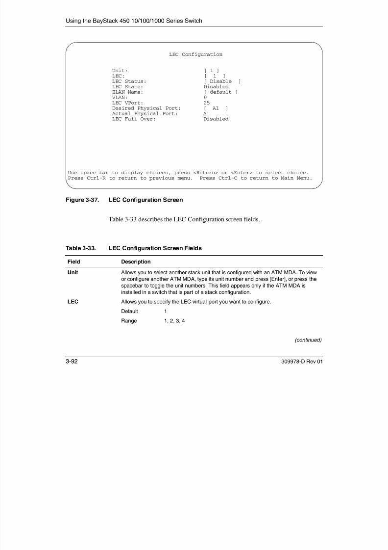
7/23/2019 Baystack 450
http://slidepdf.com/reader/full/baystack-450 252/399
3-92 309978-D Rev 01
Table 3-33. LEC Configuration Screen Fields
Field Description
Unit Allows you to select another stack unit that is configured with an ATM MDA. To view
or configure another ATM MDA, type its unit number and press [Enter], or press the
spacebar to toggle the unit numbers. This field appears only if the ATM MDA is
installed in a switch that is part of a stack configuration.
LEC Allows you to specify the LEC virtual port you want to configure.
Default 1
Range 1, 2, 3, 4
(continued)
Using the Console Interface
LEC Status Allows you to enable or disable the selected LEC.
Default Disable
Range Disable, Enable
LEC State This read-only field displays the current status of the selected LEC.Default Disabled
Range Disabled, Idle, Operational, Unknown
ELAN Name Allows you to enter a name for the ELAN that is associated with the selected LEC.
You should also verify that the ELAN you are connecting to exists on the target ATM
switch.
Default default
Range Any ASCII string of up to 20 printable characters
VLAN This read-only field displays the current VLAN that is associated with the selected
LEC. The default configuration for the LEC is 0 (no VLAN assigned).
You can assign a LEC to any currently active port-based VLAN. Use the VLAN
Configuration screen to assign the appropriate VPort number for the LEC to a VLAN.
See Appendix D, “ATM Overview,” for more information about assigning LECs to a
VLAN.
Default 0
Range 1 to 4094
LEC VPort This read-only field displays the LEC VPort (virtual por t) number that is associated
with the selected LEC. This VPort number is also shown on other CI screens (such
as the VLAN Configuration screen or the Spanning Tree Configuration screen, as
Table 3-33. LEC Configuration Screen Fields (continued)
Field Description

7/23/2019 Baystack 450
http://slidepdf.com/reader/full/baystack-450 253/399
309978-D Rev 01 3-93
appropriate).
Default 13 / 25
The four LECs are assigned VPort numbers that directly relate to
the switch version (12 port or 24 port) where they are installed. For
example, when installed in a 24-port switch, LECs 1, 2, 3, and 4
are assigned as VPorts 25, 26, 27, and 28 respectively.
Range (12-port models) = 13,14,15,16 / (24-port models) = 25,26,27,28
Desired Physical
Port
Allows you to configure the physical port (A1 or A2) for the selected LEC.
Default A1
Range A1, A2
(continued)
Using the BayStack 450 10/100/1000 Series Switch
ATM MDA Configuration
The ATM MDA Configuration screen (Figure 3-38) allows you to set up ATM
configuration parameters for your BayStack 450-2M3/2S3 MDA.
Certain fields in this screen may require you to reset the switch if you change thecurrent or default value for another value. The reset option is always preceded by ascreen prompt. Enter Yes to reset the switch; enter No to abort the option.
You can also use this screen to view the current BayStack 450-2M3/2S3 MDA:
• Hardware version• Software version
• Hardware type
• MAC addresses for physical ports A1 and A2
Actual Physical
Port
This read-only field displays the actual physical port for the selected LEC.
Default A1
Range A1, A2
LEC Fail Over This read-only field displays the LEC Fail Over setting for the ATM MDA. You can set
the LEC Fail Over field using the ATM MDA Configuration screen (see “ATM MDA
Configuration” on page 3-94).
Table 3-33. LEC Configuration Screen Fields (continued)
Field Description

7/23/2019 Baystack 450
http://slidepdf.com/reader/full/baystack-450 254/399
3-94 309978-D Rev 01
Choose ATM MDA Configuration (or press a) from the ATM Configuration Menu
to open the ATM MDA Configuration screen.

7/23/2019 Baystack 450
http://slidepdf.com/reader/full/baystack-450 255/399
Using the BayStack 450 10/100/1000 Series Switch
Port A1 MAC
Address
Read-only field that indicates the port A1 MAC address of the ATM MDA that is
currently selected.
Port A2 MAC
Address
Read-only field that indicates the port A2 MAC address of the ATM MDA that is
currently selected.
LEC Fail Over Allows you to enable or disable the LEC Fail Over feature. Note: The BayStack 450-2M3/2S3 MDA has two physical ports (A1 and A2) that are
available for LEC association. When the LEC Fail Over field value is set to Enabled,
the LEC(s) associated with a failed physical port is automatically assigned to the
remaining operational physical port. If the failed physical port recovers, the LEC(s)
will be automatically assigned to the desired port.
Default Disabled
Range Disabled, Enabled
LECS Address
Method
Allows you to configure the selected LEC to obtain LANE services from a LAN
emulation configuration server (LECS). You can choose one of three addressing
methods that the LEC will use (see Range field).
• ATM Forum -- The LEC will use an ATM Forum address.
• User Defined -- The LEC will use the User Defined Address value (see next field)
as the address of the LECS when attempting to set up the control direct to the
LECS.
• ILMI -- The switch will use the ILMI (interim local management interface) to obtainthe address of the LECS.
Default ATM Forum
Range ATM Forum, User Defined, ILMI
User DefinedAddress
Allows you to specify the ATM user-defined address to be used in the LECS Address
Method field (see previous field) This field is a 20 byte ATM address
Table 3-34. ATM MDA Configuration Screen Fields (continued)
Field Description

7/23/2019 Baystack 450
http://slidepdf.com/reader/full/baystack-450 256/399
3-96 309978-D Rev 01
Address Method field (see previous field). This field is a 20-byte ATM address
Default 39-00-00-00-00-00-00-00-00-00-00-00-00-00-00-00-00-00-00-00
Range Any 20-byte address field, where the first byte must be either 39,
45, or 47.
UNI Version Allows you to select the user-to-network interface (UNI) the LEC will use. For more
information about UNI 3.0 and UNI 3.1, refer to ATM User-Network Interface (UNI)
Specification, Version 3.0 and ATM User-Network Interface (UNI) Specification,
Version 3.1.
Default 3.1
Range 3.1, 3.0
(continued)
Using the Console Interface
ATM MDA Software Download
The ATM MDA Software Download screen (Figure 3-39) allows you to upgradeyour BayStack 450-2M3/2S3 MDA with the latest firmware code.
Choose ATM MDA Software Download (or press f) from the ATM ConfigurationMenu to open the ATM MDA Software Download screen.
PHY Type Allows you to choose the physical layer medium independent (PHY) component the
LEC will use.
You can choose between two versions of the following standard:
• Synchronous Optical Network (SONET), a standard developed under ANSI and
the Exchange Carriers Standards Association (ECSA) for digital optical
transmission.• Synchronous Digital Hierarchy (SDH), a slightly different version of the SONET
standard developed by the International Telegraph and Telephone Consultative
Committee (CCITT).
Default SONET
Range SONET, SDH
Table 3-34. ATM MDA Configuration Screen Fields (continued)
Field Description

7/23/2019 Baystack 450
http://slidepdf.com/reader/full/baystack-450 257/399
309978-D Rev 01 3-97
Using the BayStack 450 10/100/1000 Series Switch
Figure 3-39. ATM MDA Software Download Screen
Table 3-35 describes the ATM MDA Software Download screen fields.
Table 3-35. ATM MDA Software Download Screen Fields
Field Description
ATM MDA Software Download
Image Filename: [ ]TFTP Server IP Address: [ xxx.xx.xxx.xx ]
Start TFTP transfer of MDA image: [ No ]
Enter text, press <Return> or <Enter> when complete.Press Ctrl-R to return to previous menu. Press Ctrl-C to return to Main Menu.

7/23/2019 Baystack 450
http://slidepdf.com/reader/full/baystack-450 258/399
3-98 309978-D Rev 01
p
Image Filename The software image load file name.
Default Zero-length string
Range An ASCII string of up to 30 printable characters
TFTP Server IP
Address
The IP address of your TFTP load host.
Default 0.0.0.0 (no IP address assigned)
Range Four-octet dotted-decimal notation, where each octet is
represented as a decimal value, separated by a decimal point
(continued)
Using the Console Interface
Start TFTP transfer
of MDA image
Specifies whether to start the download of the BayStack 450-2M3/2S3 MDA
software image (default is No).
Use the spacebar to toggle the selection to Yes.
Press [Enter] to initiate the software download process.
To ensure that the download process is not interrupted, do not power down the
switch for approximately 10 minutes.
Default No
Range Yes, No
Table 3-35. ATM MDA Software Download Screen Fields (continued)
Field Description

7/23/2019 Baystack 450
http://slidepdf.com/reader/full/baystack-450 259/399
309978-D Rev 01 3-99

7/23/2019 Baystack 450
http://slidepdf.com/reader/full/baystack-450 260/399

7/23/2019 Baystack 450
http://slidepdf.com/reader/full/baystack-450 261/399
Using the BayStack 450 10/100/1000 Series Switch
Console Switch
Password Type
Enables password protection for accessing the console interface (CI) of a
standalone switch through a console terminal.
If you set this field to Required, you can use the Logout option to restrict access
to the CI. Thereafter, you will need to specify the correct password at the
console-terminal prompt. See Console Read-Only Switch Password and
Console Read-Write Switch Password for more information.
Default None
Range None, Local Password, RADIUS Authentication
Console Stack
Password Type
Enables password protection for accessing the console interface (CI) of any
participating switch in a stack configuration , through a console terminal.
If you set this field to Required, you can use the Logout option to restrict access
to the CI of any stack unit. Thereafter, you will need to specify the correct
password at the console-terminal prompt when accessing the stack. See
Console Read-Only Stack Password and Console Read-Write Stack Password
for more information.
Default None
Range None, Local Password, RADIUS Authentication
Table 3-36. Console/Comm Port Configuration Screen Fields (continued)
Field Description
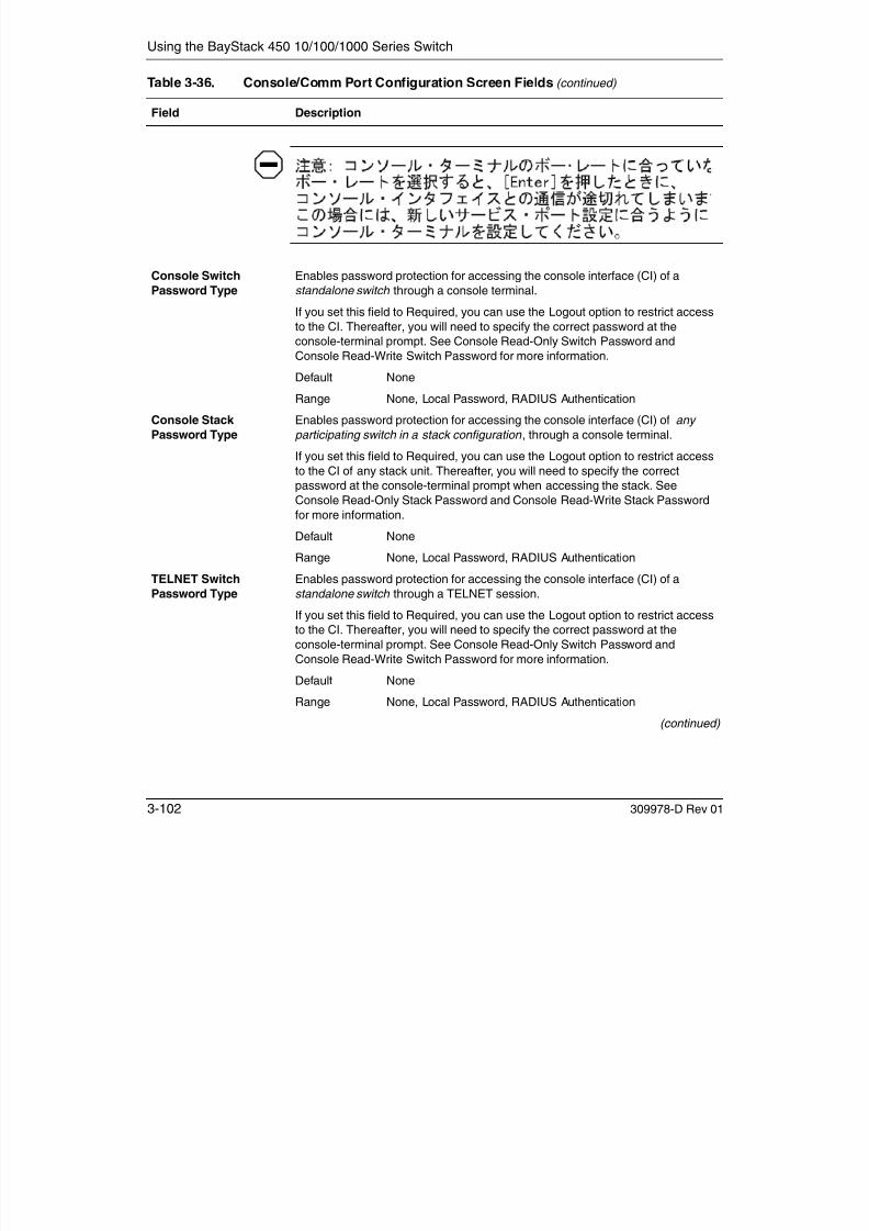
7/23/2019 Baystack 450
http://slidepdf.com/reader/full/baystack-450 262/399
3-102 309978-D Rev 01
TELNET Switch
Password Type
Enables password protection for accessing the console interface (CI) of a
standalone switch through a TELNET session.
If you set this field to Required, you can use the Logout option to restrict access
to the CI. Thereafter, you will need to specify the correct password at the
console-terminal prompt. See Console Read-Only Switch Password and
Console Read-Write Switch Password for more information.
Default None
Range None, Local Password, RADIUS Authentication
(continued)

7/23/2019 Baystack 450
http://slidepdf.com/reader/full/baystack-450 263/399
Using the BayStack 450 10/100/1000 Series Switch
At tention: Si vous changez les mots de passe par défaut du système,
assurez-vous de bien noter vos nouveaux mots de passe et de les conserver
dans un endroit sûr. Si vous perdez vos nouveaux mots de passe, vous ne
pourrez plus accéder à votre interface. Le cas échéant, veuillez contacter Nortel
Networks.
Precaución: Si modifica las contraseñas predeterminadas asignadas por el
sistema, asegúrese de anotar las nuevas contraseñas y guárdelas en un lugar
seguro. Si olvida las nuevas contraseñas, no podrá acceder al interfaz de la
consola. En ese caso, póngase en contacto con Nortel Networks para obtener
ayuda al respecto.
Attenzione: In caso di modifica delle password predefinite nel sistema,
assicurarsi di annotare le nuove password e di conservarle in un luogo sicuro.
Nel caso in cui le nuove password vengano dimenticate, non sarà possibile
accedere all'interfaccia della console. In tal caso, contattare la Nortel Networks
per avere assistenza.
Table 3-36. Console/Comm Port Configuration Screen Fields (continued)
Field Description

7/23/2019 Baystack 450
http://slidepdf.com/reader/full/baystack-450 264/399
3-104 309978-D Rev 01
Console Read-OnlyStack Password
When the Console Switch Password field is set to Local Password (for TELNET,
for Console, or for Both), this field allows read-only password access to the CI of
any participating switch in a stack configuration . Users can access the CI using
the correct password (see default), but cannot change any parameters or use the
Reset option or Reset to Default option.
Default user
Range An ASCII string of up to 15 printable characters
(continued)
Using the Console Interface
Console Read-Write
Stack Password
When the Console Switch Password field is set to Local Password (for TELNET,
for Console, or for Both), this field allows read-write password access to the CI of
any participating switch in a stack configuration . Users can log in to the CI using
the correct password (see default), and can change any parameter, except the
switch password.
You can change the default passwords for read-only access and read-write
access to a private password.
Default secure
Range Any ASCII string of up to 15 printable characters
Caution: If you change the system-supplied default passwords, be sure to
write the new passwords down and keep them in a safe place. If you forget thenew passwords, you cannot access the console interface. In that case, contact
Nortel Networks for help.
Achtung: Wenn Sie die für das System standardmäßig eingestellten Paßwörter
ändern, notieren Sie sich die neuen Paßwörter, und bewahren Sie sie an einem
sicheren Ort auf. Falls Sie die neuen Paßwörter vergessen, können Sie nicht
mehr auf die Konsolenschnittstelle zugreifen. Wenden Sie sich in diesem Fall an
Nortel Networks, um Unterstützung zu erhalten.
At tention: Si vous changez les mots de passe par défaut du système,
assurez-vous de bien noter vos nouveaux mots de passe et de les conserver
dans un endroit sûr. Si vous perdez vos nouveaux mots de passe, vous ne
pourrez plus accéder à votre interface. Le cas échéant, veuillez contacter Nortel
Networks
Table 3-36. Console/Comm Port Configuration Screen Fields (continued)
Field Description

7/23/2019 Baystack 450
http://slidepdf.com/reader/full/baystack-450 265/399
309978-D Rev 01 3-105
Networks.
Precaución: Si modifica las contraseñas predeterminadas asignadas por el
sistema, asegúrese de anotar las nuevas contraseñas y guárdelas en un lugar
seguro. Si olvida las nuevas contraseñas, no podrá acceder al interfaz de la
consola. En ese caso, póngase en contacto con Nortel Networks para obtener
ayuda al respecto.
(continued)
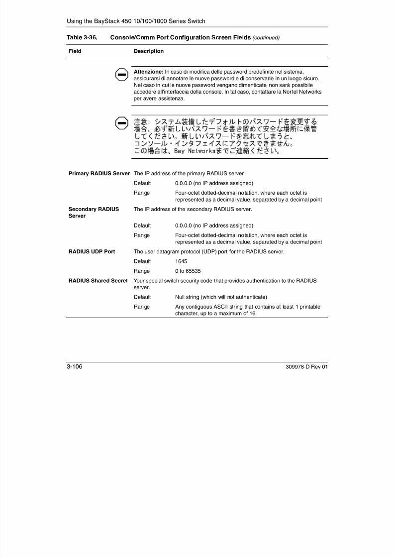
7/23/2019 Baystack 450
http://slidepdf.com/reader/full/baystack-450 266/399
Using the Console Interface
Identify Unit Numbers
When selected from the Main Menu, this option identifies the current unitnumbering of each unit in a stack configuration by lighting the correspondingnumber of green (100 Mb/s) port LEDs for approximately 10 seconds. Forexample, in a four-unit stack, unit 1 displays one LED, unit 2 displays two LEDs,unit 3 displays three LEDs, and unit 4 displays four LEDs. The LED displays
temporarily override any existing 100 Mb/s LED indications on all unit LEDdisplay panels.
Renumber Stack Units
The Renumber Stack Units screen (Figure 3-41) allows you to renumber the unitsconfigured in the stack.
When selected, this option identifies the unit number of each stack unit by lightingthe corresponding number of 100 Mb/s port LEDs on each unit for approximately
10 seconds. For example, unit 3 will display three LEDs.
Choose Renumber Stack Units (or press n) from the main menu to open the
Note: This menu option appears only when the switch is participating in astack configuration.
Note: This menu option and screen appear only when the switch isparticipating in a stack configuration.

7/23/2019 Baystack 450
http://slidepdf.com/reader/full/baystack-450 267/399
309978-D Rev 01 3-107
( p ) p
Renumber Stack Units screen.
Using the BayStack 450 10/100/1000 Series Switch
Figure 3-41. Renumber Stack Units Screen
Table 3-37 describes the Renumber Stack Units screen options:
Table 3-37. Renumber Stack Units Screen Options
Option Description
Current Unit Number Read-only field listing the current unit number of each of the configured stack units.
The entries in this column are displayed in order of their current physical cabling
Renumber Stack Units
Current Unit Number MAC Address New Unit Number------------------- ---------------------------- ---------------
[ 1 ] 00-60-fd-77-a6-0c [ 1 ][ 2 ] 00-60-fd-77-a5-f0 [ 2 ][ 3 ] 00-60-fd-77-a4-4c [ 3 ][ 4 ] 00-60-fd-77-ab-84 [ 4 ]
Renumbering stack units will cause an automatic Reset to Current Settings tooccur across the entire stack. The current configuration will be adapted tothe new numbering scheme. Check the stack configuration after the reset toconfirm the desired configuration is set.
Are you sure you want to renumber switches with the new settings? [ No ]
Use space bar to display choices, press <Return> or <Enter> to select choice.Press Ctrl-R to return to previous menu. Press Ctrl-C to return to Main Menu.

7/23/2019 Baystack 450
http://slidepdf.com/reader/full/baystack-450 268/399
3-108 309978-D Rev 01
with respect to the base unit, and can show nonconsecutive unit numbering if oneor more units were previously moved or modified. The entries can also include unit
numbers of units that are no longer participating in the stack (not currently active).
MAC Address Read-only field listing the MAC address of the corresponding unit listed in the
Current Unit Number field.
New Unit Number User-settable field showing the current unit number of each unit in the stack. You
can change any of the fields, as required. You can also delete entries by typing
zero (0) or using the spacebar to clear the field when the unit is not in the stack.
Default Current stack order
Range 1 to 8
(continued)
Using the Console Interface
Display Hardware Units
The Hardware Unit Information screen (Figure 3-42) lists the switch models,including any installed MDA and Cascade modules, that are configured in yourstandalone or stack configuration.
Choose Display Hardware Units (or press h) from the main menu to open theHardware Unit Information screen.
Renumber units with
new setting?
Specifies whether to start the renumbering process (default is No). Use the
spacebar to toggle the selection to Yes. The Unit LEDs display the new numbering
order.
Renumbering resets the switch with the current configuration values.
When you select this option, the switch resets, runs a self-test, then displays theNortel Networks logo screen. After you press [Ctrl]-Y at the screen prompt, the
console screen temporarily displays the (standalone) BayStack 450 main menu.
Then, within 20 seconds, the console screen refreshes and displays the main
Menu for the stack configuration.
Default No
Range No, Yes
Table 3-37. Renumber Stack Units Screen Options (continued)
Option Description

7/23/2019 Baystack 450
http://slidepdf.com/reader/full/baystack-450 269/399
309978-D Rev 01 3-109
Using the BayStack 450 10/100/1000 Series Switch
Figure 3-42. Hardware Unit Information Screen
Spanning Tree ConfigurationThe Spanning Tree Configuration Menu (Figure 3-43) allows you to viewspanning tree parameters and configure individual switch ports to participate inthe spanning tree algorithm (STA).
To modify any of the spanning tree parameters, see your SNMP documentation.
Hardware Unit Information
Switch Model MDA Model Cascade MDA---------------- --------- -----------
Unit #1 BayStack 450-24T None 400-ST1Unit #2 BayStack 450-12F 450-1SX 400-ST1Unit #3 BayStack 450-24T 400-4FX 400-ST1Unit #4 BayStack 410-24T 400-4FX 400-ST1Unit #5 BayStack 450-24T None 400-ST1Unit #6 BayStack 450-12T 450-1SX 400-ST1Unit #7 BayStack 450-24T 400-4FX 400-ST1Unit #8 BayStack 410-24T None 400-ST1
Press Ctrl-R to return to previous menu. Press Ctrl-C to return to Main Menu.

7/23/2019 Baystack 450
http://slidepdf.com/reader/full/baystack-450 270/399
3-110 309978-D Rev 01
Choose Spanning Tree Configuration (or press p) from the main menu to open theSpanning Tree Configuration Menu.
Using the Console Interface
Figure 3-43. Spanning Tree Configuration Menu
Table 3-38 describes the Spanning Tree Configuration Menu options:
Table 3-38. Spanning Tree Configuration Menu Options
Option Description
Spanning Tree Port Configuration... Displays the Spanning Tree Port Configuration screen (see
“Spanning Tree Port Configuration” on page 3-112).
Spanning Tree Configuration Menu
Spanning Tree Port Configuration...Display Spanning Tree Switch SettingsReturn to Main Menu
Use arrow keys to highlight option, press <Return> or <Enter> to select option.Press Ctrl-R to return to previous menu. Press Ctrl-C to return to Main Menu.

7/23/2019 Baystack 450
http://slidepdf.com/reader/full/baystack-450 271/399
309978-D Rev 01 3-111
Display Spanning Tree Switch Settings Displays the Spanning Tree Switch Settings screen (see“Display Spanning Tree Switch Settings” on page 3-115).
Return to Main Menu Exits the Spanning Tree Configuration Menu and displays the
main menu.
Using the BayStack 450 10/100/1000 Series Switch
Spanning Tree Port Configuration
The Spanning Tree Port Configuration screen allows you to configure individualswitch ports or all switch ports for participation in the spanning tree.
Figures 3-44 and 3-45 show sample port configurations for the two Spanning TreePort Configuration screens.
Choose Spanning Tree Port Configuration (or press c) from the Spanning TreeConfiguration Menu to open the Spanning Tree Port Configuration screen.
Note: If spanning tree participation of any trunk member is changed (enabledor disabled), the spanning tree participation of all members of that trunk is
changed similarly.
Spanning Tree Port Configuration
Unit: [ 1 ]Port Trunk Participation Priority Path Cost State---- ----- ------------------- -------- --------- ----------1 [ Normal Learning ] 128 10 Forwarding2 [ Normal Learning ] 128 10 Forwarding
3 [ Normal Learning ] 128 10 Forwarding4 [ Normal Learning ] 128 10 Forwarding5 [ Normal Learning ] 128 10 Forwarding6 1 [ Normal Learning ] 128 10 Forwarding7 1 [ Normal Learning ] 128 10 Forwarding8 [ Normal Learning ] 128 10 Forwarding9 1 [ Normal Learning ] 128 10 Forwarding10 [ Normal Learning ] 128 10 Forwarding11 [ Normal Learning ] 128 10 Forwarding12 [ Normal Learning ] 128 10 Forwarding13 3 [ Normal Learning ] 128 10 Forwarding

7/23/2019 Baystack 450
http://slidepdf.com/reader/full/baystack-450 272/399
3-112 309978-D Rev 01
Figure 3-44. Spanning Tree Port Configuration Screen (1 of 2)
14 3 [ Normal Learning ] 128 10 ForwardingMore...
Press Ctrl-N to display choices for additional ports..Use space bar to display choices, press <Return> or <Enter> to select choice.Press Ctrl-R to return to previous menu. Press Ctrl-C to return to Main Menu.
Using the Console Interface
Figure 3-45. Spanning Tree Port Configuration Screen (2 of 2)
Table 3-39 describes the Spanning Tree Port Configuration screen fields.
Table 3-39. Spanning Tree Port Configuration Screen Fields
Field Description
Thi fi ld l if h i h i i i i i k fi i Th fi ld
Spanning Tree Port Configuration
Unit: [ 1 ]Port Trunk Participation Priority Path Cost State---- ----- ------------------- -------- --------- ----------15 [ Normal Learning ] 128 5 Forwarding16 [ Normal Learning ] 128 5 Forwarding17 1 [ Normal Learning ] 128 10 Forwarding
18 [ Normal Learning ] 128 10 Forwarding19 4 [ Normal Learning ] 128 10 Forwarding20 4 [ Normal Learning ] 128 10 Forwarding21 [ Normal Learning ] 128 10 Forwarding22 5 [ Normal Learning ] 128 10 Forwarding23 5 [ Normal Learning ] 128 10 Forwarding24 [ Normal Learning ] 128 10 Forwarding25 2 [ Normal Learning ] 128 10 Forwarding26 2 [ Normal Learning ] 128 10 Forwarding27 [ Normal Learning ] 128 10 Forwarding28 [ Normal Learning ] 128 10 ForwardingSwitch [ Normal Learning ]Stack [ Normal Learning ]
Press Ctrl-P to display choices for ports 1-14.Use space bar to display choices, press <Return> or <Enter> to select choice.Press Ctrl-R to return to previous menu. Press Ctrl-C to return to Main Menu.

7/23/2019 Baystack 450
http://slidepdf.com/reader/full/baystack-450 273/399
309978-D Rev 01 3-113
Unit This field appears only if the switch is participating in a stack configuration. The fieldallows you to select the number of the unit you want to view. To view another unit, type its
unit number and press [Enter], or press the spacebar on your keyboard to toggle the unit
numbers.
Port Indicates the switch port numbers that correspond to the field values in that row of the
screen (for example, the field values in row 2 apply to switch port 2). Note that the values
in the Switch row affect all switch ports and, when the switch is part of a stack, the values
in the Stack row affect all ports in the entire stack.
Trunk This read-only field indicates the trunks that correspond to the switch ports specified inthe Trunk Members fields of the Trunk Configuration screen (see “MultiLink Trunk
Configuration” on page 3-64).
(continued)
Using the BayStack 450 10/100/1000 Series Switch
Participation Allows you to configure any (or all) of the switch ports for spanning tree participation.
When an individual port is a trunk member (see Trunk field), changing this setting for one
of the trunk members changes the setting for all members of that trunk. You should
consider how this can change your network topology before you change this setting (see
“MultiLink Trunking Configuration Rules” on page 1-90).
The Fast Learning parameter is the same as Normal Learning, except that the state
transition timer is shortened to 2 seconds.
Default Normal Learning
Range Normal Learning, Fast Learning, Disabled
Priority This read-only field is a bridge spanning tree parameter that prioritizes the port’s lowest
path cost to the root. When one or more ports have the same path cost, the STA selects
the path with the highest priority (lowest numerical value). See also Path Cost.
Default 128
Range 0 to 255
Path Cost This read-only field is a bridge spanning tree parameter that determines the lowest path
cost to the root.
Default 10 or 100 (1 for gigabit port)
Path Cost = 1000/LAN speed (in Mb/s)
The higher the LAN speed, the lower the path cost.
See also Priority.
Range 1 to 65535
State This read-only field indicates the current port state within the spanning tree network.
Each port can transition to various states, as determined by the Participation field setting.
For example, when the Participation field is set to Disabled, the port does not participate
i th STA d t iti t th F di t t (th d f lt) Wh th P ti i ti
Table 3-39. Spanning Tree Port Configuration Screen Fields (continued)
Field Description

7/23/2019 Baystack 450
http://slidepdf.com/reader/full/baystack-450 274/399
3-114 309978-D Rev 01
in the STA and transitions to the Forwarding state (the default). When the Participationfield is set to Normal Learning or Fast Learning, the port transitions from the Disabled
state through the Blocking, Listening, and Learning states before entering the
Forwarding state.
Default Topology dependent
Range Disabled, Blocking, Listening, Learning, Forwarding

7/23/2019 Baystack 450
http://slidepdf.com/reader/full/baystack-450 275/399
Using the BayStack 450 10/100/1000 Series Switch
Table 3-40 describes the Spanning Tree Switch Settings parameters.
Table 3-40. Spanning Tree Switch Settings Parameters
Parameter Description
Bridge Priority Indicates the management-assigned priority value of the bridge ID in hexadecimal
notation, which is the most significant byte of the bridge ID. The STA uses this parameter
to determine the root bridge (or designated bridge). For example, the bridge with the
lowest bridge ID becomes the root bridge, with Bridge Priority values compared first,followed by the hardware addresses.
Default 8000
Range 0 to 65535
Designated
Root
Indicates the bridge ID of the root bridge, as determined by the STA.
Default 8000 (bridge_id)
Range 0 to 65535Root Port Indicates the specific unit in a stack or standalone switch’s port number that offers the
lowest path cost to the root bridge.
Default Unit: 0 / Port: 0
Range Unit: 0 to 8 / Port: 0 to 28
Root Path Cost Indicates the path cost from this switch port to the root bridge.
Default 0
Range Not applicable
Hello Time Indicates the Actual Hello Interval, the amount of time between transmissions of
configuration Bridge Protocol Data Units (BPDUs) that the root bridge is currently using.
Note that all bridges par ticipating in the spanning tree network use the root bridge’s Hello
Interval parameter value. See also Bridge Hello Time.
Default 2 seconds
Range 1 to 10 seconds

7/23/2019 Baystack 450
http://slidepdf.com/reader/full/baystack-450 276/399
3-116 309978-D Rev 01
Range 1 to 10 seconds
Maximum Age
Time
Indicates the Maximum Age Time parameter value that the root bridge is currently using.
This value specifies the maximum age that a Hello message can attain before it is
discarded.
Note that the root bridge’s Maximum Age Time parameter value becomes the actual
Maximum Age Time parameter value for all bridges participating in the spanning tree
network. See also Bridge Maximum Age Time.
Default 20 secondsRange 6 to 40 seconds
(continued)
Using the Console Interface
Forward Delay Indicates the Forward Delay parameter value that the root bridge is currently using. This
value specifies the amount of time that the bridge por ts remain in the Listening and
Learning states before entering the Forwarding state.
Note that the root bridge’s Forward Delay parameter value becomes the actual Forward
Delay parameter value for all bridges participating in the spanning tree network. See also
Bridge Forward Delay.
Default 15 seconds
Range 4 to 30 seconds
Bridge Hello
Time
Indicates the Hello Interval (the amount of time between transmissions of BPDUs)
specified by management for this bridge. This parameter takes effect only when this
bridge becomes the root bridge.
Note that, although you can set the Hello Interval for a bridge using bridge management
software, once the spanning tree computation process is complete, all bridges
participating in the spanning tree network use the root bridge’s Hello Interval parameter
value. If any bridge becomes the root bridge, its Hello Interval parameter value becomes
the Actual Hello Interval parameter value for all bridges participating in the spanning tree
network. See also Hello Time.
Default 2 seconds
Range 1 to 10 seconds
BridgeMaximum Age
Time
Specifies the maximum age (in seconds) that a Hello message can attain before it isdiscarded. This parameter, specified by management for this bridge, takes effect only
when the bridge becomes the root bridge.
Note that, if this bridge becomes the root bridge, its Maximum Age Time parameter value
becomes the Actual Maximum Age Time parameter value for all bridges participating in
the spanning tree network. See also Maximum Age Time.
Default 20 seconds
Range 6 to 40 seconds
Table 3-40. Spanning Tree Switch Settings Parameters (continued)
Parameter Description

7/23/2019 Baystack 450
http://slidepdf.com/reader/full/baystack-450 277/399
309978-D Rev 01 3-117
Range 6 to 40 seconds
Bridge Forward
Delay
Indicates the Forward Delay parameter value specified by management for this bridge.
This parameter takes effect only when this bridge becomes the root bridge.
The Forward Delay parameter value specifies the amount of time that the bridge ports
remain in the Listening and Learning states before entering the Forwarding state.
Note that all bridges participating in the spanning tree network use the root bridge’s
Forward Delay parameter value. See also Forward Delay.
Default 15 seconds
Range 4 to 30 seconds
Using the BayStack 450 10/100/1000 Series Switch
TELNET/SNMP Manager List ConfigurationThe TELNET/ SNMP Manager List Configuration screen (Figure 3-47) allowsyou to specify up to 10 user-assigned host IP addresses that are allowed TELNETand SNMP access to the switch. When you set the TELNET Access value toEnabled, you can communicate with the BayStack 450 switch from a remoteconsole terminal and can have up to four active TELNET sessions at one time.
Choose TELNET/ SNMP Mgr List Configuration (or press t) from the main menuto open the TELNET/ SNMP Manager List Configuration screen.
Note: In a mixed-stack configuration that includes one or more BusinessPolicy Switches, the Allowed Source IP Address list cannot be used for SNMPsecurity.
TELNET/SNMP Manager List Configuration
TELNET Access: [ Enabled ]Login Timeout: [ 1 minute ]Login Retries: [ 3 ]Inactivity Timeout: [ 15 minutes ]Event Logging: [ All ]
Allowed Source IP Address Allowed Source Mask------------------------- -------------------------
[ 0.0.0.0 ] [ 0.0.0.0 ][ 255.255.255.255 ] [ 255.255.255.255 ][ 255.255.255.255 ] [ 255.255.255.255 ][ 255.255.255.255 ] [ 255.255.255.255 ][ 255.255.255.255 ] [ 255.255.255.255 ][ 255.255.255.255 ] [ 255.255.255.255 ][ 255.255.255.255 ] [ 255.255.255.255 ][ 255.255.255.255 ] [ 255.255.255.255 ][ 255.255.255.255 ] [ 255.255.255.255 ]

7/23/2019 Baystack 450
http://slidepdf.com/reader/full/baystack-450 278/399
3-118 309978-D Rev 01
Figure 3-47. TELNET/SNMP Manager List Configuration Screen
Table 3-41 describes the TELNET/SNMP Manager List Configuration screenfields.
[ ] [ ][ 255.255.255.255 ] [ 255.255.255.255 ]
Use space bar to display choices, press <Return> or <Enter> to select choice.Press Ctrl-R to return to previous menu. Press Ctrl-C to return to Main Menu.
Using the Console Interface
Table 3-41. TELNET/SNMP Manager List Configuration Screen Fields
Field Description
TELNET Access Allows remote access to the CI through a TELNET session.
Default Enabled
Range Enabled, Disabled
Login Timeout Specifies the amount of time you have to enter the correct password at the
console-terminal prompt.
Default 1 minute
Range 0 to 10 minutes (0 indicates “no timeout”)
Login Retries Specifies the number of times you can enter an incorrect password at the
console-terminal prompt before the session is terminated.
Default 3
Range 1 to 100Inactivity
Timeout
Specifies the amount of time the session can be inactive before it is terminated.
Default 15 minutes
Range 0 to 60 minutes (0 indicates “no timeout”)
Event Logging Specifies the types of events that will be displayed in the Event Log screen (see “Display
Event Log” on page 3-128).
Default All
Range All, None, Accesses, Failures
All: Logs the following TELNET events to the Event Log screen:
• TELNET connect: Indicates the IP address and access mode of a TELNET session.
• TELNET disconnect: Indicates the IP address of the remote host and the access
mode, due to either a logout or inactivity.
• Failed TELNET connection attempts: Indicates the IP address of the remote host
whose IP address is not on the list of allowed addresses, or indicates the IP addressf th t h t th t did t l th t d

7/23/2019 Baystack 450
http://slidepdf.com/reader/full/baystack-450 279/399
309978-D Rev 01 3-119
of the remote host that did not supply the correct password.
None: Indicates that no TELNET events will be logged in the Event Log screen.
Accesses : Logs only TELNET connect and disconnect events in the Event Log screen.
Failures: Logs only failed TELNET connection attempts in the Event Log screen.
(continued)
Using the BayStack 450 10/100/1000 Series Switch
Allowed Source
IP Address
Specifies up to 10 user-assigned host IP addresses that are allowed TELNET and SNMP
access to the switch.
Default 0.0.0.0 (no IP address assigned)
Range Four-octet dotted-decimal notation, where each octet is represented
as a decimal value, separated by a decimal pointAllowed Source
Mask
Specifies up to 10 user-assigned allowed source address masks. The remote IP address
is masked with the Allowed Source Mask and, if the resulting value equals the Allowed
Source IP address, the connection is allowed.
For example, a connection would be allowed with the following settings:
Remote IP address = 192.0.1.5
Allowed Source IP Address = 192.0.1.0
Allowed Source Mask = 255.255.255.0
Default 0.0.0.0 (no IP mask assigned)
Range Four-octet dotted-decimal notation, where each octet is represented
as a decimal value, separated by a decimal point
Table 3-41. TELNET/SNMP Manager List Configuration Screen Fields (continued)
Field Description

7/23/2019 Baystack 450
http://slidepdf.com/reader/full/baystack-450 280/399
3-120 309978-D Rev 01
Using the Console Interface
Software DownloadThe Software Download screen (Figure 3-48) allows you to revise the BayStack450 switch software image that is located in nonvolatile flash memory.
To download the BayStack 450 switch software image, you need a properlyconfigured Trivial File Transfer Protocol (TFTP) server in your network, and anIP address for the switch (or stack, if configured). To learn how to configure theswitch or stack IP address, see “IP Configuration/Setup” on page 3-9.
You can monitor the software download process by observing the BayStack 450switch LEDs (see “LED Indications During the Download Process” onpage 3-123).
Caution: Do not interrupt power to the device during the software downloadprocess. If the power is interrupted, the firmware image can become corrupted.
Achtung: Unterbrechen Sie die Stromzufuhr zum Gerät nicht, während dieSoftware heruntergeladen wird. Bei Unterbrechung der Stromzufuhr kann dasFirmware-Image beschädigt werden.
Attention: Ne pas couper l'alimentation de l'appareil pendant le chargementdu logiciel. En cas d'interruption, le programme résident peut être endommagé.
Precaución: No interrumpa la alimentación del dispositivo durante elproceso de descarga del software. Si lo hace, puede alterar la imagen de la
programación (firmware).
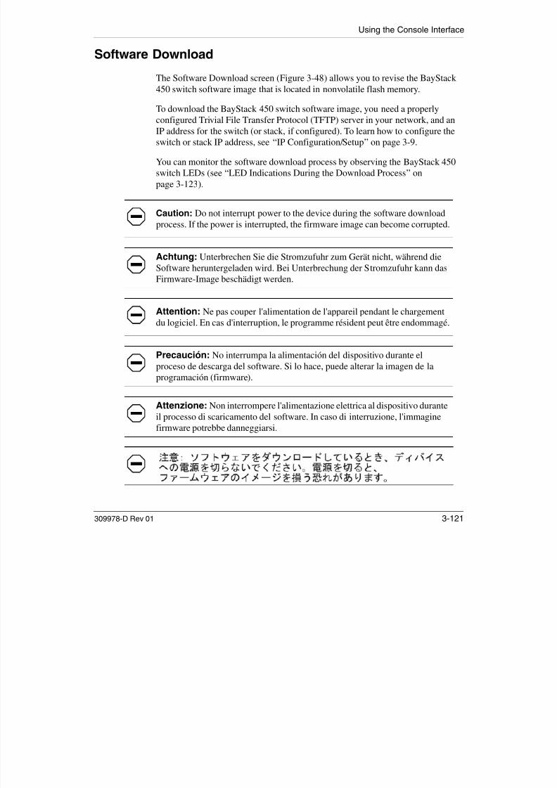
7/23/2019 Baystack 450
http://slidepdf.com/reader/full/baystack-450 281/399
309978-D Rev 01 3-121
p g ( )
Attenzione: Non interrompere l'alimentazione elettrica al dispositivo duranteil processo di scaricamento del software. In caso di interruzione, l'immaginefirmware potrebbe danneggiarsi.
Using the BayStack 450 10/100/1000 Series Switch
Choose Software Download (or press f) from the main menu to open the SoftwareDownload screen.
Figure 3-48. Software Download Screen
Table 3-42 describes the Software Download screen fields.
Table 3-42. Software Download Screen Fields
Field Description
Image Filename The software image load file name (Figure 3-48 shows an example image file name).
Software Download
Image Filename: [ b4504002.img ]TFTP Server IP Address: [ xxx.xxx.xxx.xxx ]
Start TFTP Load of New Image: [ No ]
Enter text, press <Return> or <Enter> when complete.Press Ctrl-R to return to previous menu. Press Ctrl-C to return to Main Menu.

7/23/2019 Baystack 450
http://slidepdf.com/reader/full/baystack-450 282/399
3-122 309978-D Rev 01
Image Filename e s a e age ad e a e ( gu e 3 8 s s a e a p e age e a e)
Note: Certain software releases may require you to download two images: the boot
code image and the agent image . For proper operation of the switch, the new boot code
image must be downloaded before the agent image is downloaded.
Default Zero-length string
Range An ASCII string of up to 30 printable characters
(continued)
Using the Console Interface
LED Indications During the Download Process
The software download process automatically completes without userintervention. The process erases the contents of flash memory and replaces it witha new software image. Be careful not to interrupt the download process until afterit runs to completion (the process can take up to 10 minutes, depending onnetwork conditions).
TFTP Server IP
Address
The IP address of your TFTP load host.
Default 0.0.0.0 (no IP address assigned)
Range Four-octet dotted-decimal notation, where each octet is represented
as a decimal value, separated by a decimal point
Start TFTP Loadof New Image
Specifies whether to start the download of the switch software image (default is No).
Use the spacebar to toggle the selection to Yes.
Press [Enter] to initiate the software download process.
Note: The software download process can take up to 60 seconds to complete (or more
if the load host path is congested or there is a high volume of network traffic).
To ensure that the download process is not interrupted, do not power down the switch for
approximately 10 minutes.
Default No
Range Yes, No
Note: If problems occur during the software download process, the SoftwareDownload screen displays error codes that define the problem. The error codes
Table 3-42. Software Download Screen Fields(continued)
Field Description

7/23/2019 Baystack 450
http://slidepdf.com/reader/full/baystack-450 283/399
309978-D Rev 01 3-123
When the download process is complete, the switch automatically resets and thenew software image initiates a self-test. The BayStack 450 switch Self-Test screen(see Figure 3-54 on page 3-131) briefly displays the results and is followed by theNortel Networks logo screen. Press [Ctrl]-Y from the Nortel Networks logoscreen to access the BayStack 450 switch main menu.
are described in Chapter 4, “Troubleshooting.”
Using the BayStack 450 10/100/1000 Series Switch
During the download process, the BayStack 450 switch is not operational. Youcan monitor the progress of the download process by observing the LEDindications.
Table 3-43 describes the LED indications during the software download process.
Note: The LED indications described in Table 3-43 apply to a 24-port switchmodel. Although a 12-port switch provides similar LED indications, the LEDindication sequence is associated within the 12-port range.
Table 3-43. LED Indications During the Software Download Process
Phase Description LED Indications
1 The switch downloads the new
software image.
100 Mb/s port status LEDs (ports 18 to 24 only): The
LEDs begin to turn on in succession beginning with port 24,
which indicates the progress of the download process. WhenLEDs 18 to 24 are all on, the switch has received the new
software image successfully.
2 The switch erases the flash
memory.
100 Mb/s port status LEDs (ports 1 to 12 only): The LEDs
begin to turn on in succession beginning with port 1, which
indicates that various sectors of the switch’s flash memory
are being erased. When LEDs 1 to 12 are all on, the switch’s
flash memory has been erased.
3 The switch programs the new
software image into the flash
memory.
100 Mb/s port status LEDs (ports 1 to 8 only): The LEDs
begin to turn on in succession beginning with port 1, which
indicates that the new software image is being programmed
into the switch’s flash memory. When LEDs 1 to 8 are all on,
the new software image has been programmed successfully
into the switch’s flash memory.
4 The switch resets automatically. After the reset completes, the new software image initiates
the switch self-test, which comprises various diagnostic
routines and subtests.
Th LED di l i i di h h

7/23/2019 Baystack 450
http://slidepdf.com/reader/full/baystack-450 284/399
3-124 309978-D Rev 01
The LEDs display various patterns to indicate that the
subtests are in progress. The results of the self-test are
displayed briefly in the Self-Test screen, after which the CI
screens appear.
Using the Console Interface
Configuration FileThe Configuration File Download/Upload screen (Figure 3-49) allows you tostore your switch/stack configuration parameters on a TFTP server.
You can retrieve the configuration parameters of a standalone switch or an entirestack and use the retrieved parameters to automatically configure a replacementswitch or stack. Certain requirements apply when automatically configuring a
switch or stack using this feature (see “Requirements” on page 3-126). You mustset up the file on your TFTP server and set the file name read/write permission toEnabled before you can save the configuration parameters.
Although most configuration parameters are saved to the configuration file,certain parameters are not saved (see Table 3-45 on page 3-127).
Choose Configuration File (or press g) from the main menu to open theConfiguration File Download/Upload screen.
Configuration File Download/Upload
Configuration Image Filename: [ ]TFTP Server IP Address: [ xxx.xxx.xxx.x ]Copy Configuration Image to Server: [ No ]Retrieve Configuration Image from Server: [ No ]

7/23/2019 Baystack 450
http://slidepdf.com/reader/full/baystack-450 285/399
309978-D Rev 01 3-125
Figure 3-49. Configuration File Download/Upload Screen
Table 3-44 describes the Configuration File Download/Upload screen fields.
Enter text, press <Return> or <Enter> when complete.Press Ctrl-R to return to previous menu. Press Ctrl-C to return to Main Menu.
Using the BayStack 450 10/100/1000 Series Switch
Table 3-44. Configuration File Download/Upload Screen Fields
Field Description
Configuration Image
Filename
The file name you have chosen for the configuration file. Choose a meaningful
file name that will allow you to identify the file for retrieval when required. The file
must already exist on your TFTP server and must be read/write enabled.
Default Zero-length string
Range An ASCII string of up to 30 printable characters
TFTP Server IP Address The IP address of your TFTP load host.
Default 0.0.0.0 (no IP address assigned)
Range Four-octet dotted-decimal notation, where each octet is
represented as a decimal value, separated by a decimal point
Copy ConfigurationImage to Server
Specifies whether to copy the presently configured switch/stack parameters tothe specified TFTP server (default is No).
Use the spacebar to toggle the selection to Yes.
Press [Enter] to initiate the process.
Default No
Range Yes, No
Retrieve ConfigurationImage from Server Specifies whether to retrieve the stored switch/stack configuration parametersfrom the specified TFTP server (default is No). If you choose Yes, the download
process begins immediately and, when completed, causes the switch/stack to
reset with the new configuration parameters.
Use the spacebar to toggle the selection to Yes.
Press [Enter] to initiate the process.
Default No
Range Yes, No

7/23/2019 Baystack 450
http://slidepdf.com/reader/full/baystack-450 286/399
3-126 309978-D Rev 01
Requirements
• The Configuration File feature can be used only to copy standalone switch configuration parameters to other standalone switches or to copy stack
configuration parameters to other stack configurations.
For example, you cannot duplicate the configuration parameters of a unit in astack configuration and use it to configure a standalone switch.
Using the Console Interface
• A configuration file obtained from a standalone switch can be used only toconfigure other standalone switches that have the same software revision andmodel type as the donor standalone switch.
You can check your switch’s current software revision using the SystemCharacteristics screen (see “System Characteristics” on page 3-16).
• A configuration file obtained from a stack unit can be used only to configureother “mirror-imaged” stacks. For example, the “new” stack must have the
same number of switches and model types (in the same unit number locations)and the same software version as the stack in which the donor stack unitresides.
You can check your switch’s current software revision using the SystemCharacteristics screen (see “System Characteristics” on page 3-16).
Reconfigured stacks are configured according to the unit order number of the
donor unit. For example, the configuration file parameters from a donor unitwith physical ID x are used to reconfigure the unit with physical ID x.
• The configuration file also duplicates any settings that exist for any MDA thatis installed in the donor switch.
If you use the configuration file to configure another switch that has the sameMDA model installed, the configuration file settings will also apply to andoverride the existing MDA settings.
Table 3-45. Parameters Not Saved to the Configuration File
These parameters are not saved: Used in this screen: See page:
In-Band Stack IP Address IP Configuration/Setup 3-9
In-Band Switch IP Address
In-Band Subnet MaskDefault Gateway

7/23/2019 Baystack 450
http://slidepdf.com/reader/full/baystack-450 287/399
309978-D Rev 01 3-127
Console Read-Only Switch Password Console/Comm Port Configuration 3-100
Console Read-Write Switch Password
Console Read-Only Stack Password
Console Read-Write Stack Password
Configuration Image Filename Configuration File Download/Upload 3-125TFTP Server IP Address
Using the BayStack 450 10/100/1000 Series Switch
Display Event LogThis section describes the various functions of the Event Log screen (Figure3-50).
When the switch is part of a stack configuration, the Event Log screen displaysonly the data for the specific unit you are connected to through the Console/ Comm port. However, if you are connected to a stack unit through a TELNET
session, the Event Log screen displays the data for the base unit of that stackconfiguration.
Choose Display Event Log (or press e) from the main menu to open the Event Logscreen.
Note: This screen does not refresh dynamically to show new entries. Torefresh the screen, press [Ctrl]-P.
Event Log
Entry Number: 4 sysUpTime: 00:14:36 Reset Count: 2Connection logout, IP address: 38.227.40.8, access mode: no security.
Entry Number: 3 sysUpTime: 00:13:35 Reset Count: 2Connection logout, IP address: 38.227.40.8, access mode: no security.
Entry Number: 2 sysUpTime: 00:00:53 Reset Count: 2Successful connection from IP address: 38.227.40.8, access mode: no security.
Entry Number: 1 sysUpTime: 00:00:00 Reset Count: 1Software downloaded to BayStack Model 450-24T HW:RevA FW:V1.00 SW:V1.0.0.0

7/23/2019 Baystack 450
http://slidepdf.com/reader/full/baystack-450 288/399
3-128 309978-D Rev 01
Figure 3-50. Event Log Screen
Press Ctrl-P to see previous display. Press Ctrl-N to see more entries.Press Ctrl-R to return to previous menu. Press Ctrl-C to return to Main Menu.
Using the Console Interface
The Event Log screen provides the following information:
• Software download: Indicates the new software version.
• Authentication failure: Indicates any attempted SNMP get or set access thatspecified an invalid community string.
• TELNET session status: Indicates various TELNET events. (For details onconfiguring this feature, see “TELNET/SNMP Manager List Configuration”
on page 3-118.)• Operational exception: Indicates that the microprocessor has received an
exception at the specified vector number and dumps stack registers.
• Excessive bad entries: Displays excessive bad entries detected by firmware.
• Write threshold: Displays event entries that exceeded the write threshold.
• Flash update: Displays status of flash updates.
Excessive Bad Entries
If the firmware detects excessive bad entries in the event log’s flash memory(errors exceeding 75 percent of the memory buffer), the event log is cleared (allentries are discarded) and an event entry is displayed in the Event Log screen.
Figure 3-51 shows an example of the event log entry for this type of event.
Entry Number: 4 sysUpTime: 00:20:53 Reset Count: 2Excessive bad entries in log, Event Log cleared.

7/23/2019 Baystack 450
http://slidepdf.com/reader/full/baystack-450 289/399
309978-D Rev 01 3-129
Figure 3-51. Sample Event Log Entry Showing Excessive Bad Entries
Using the BayStack 450 10/100/1000 Series Switch
Write ThresholdTo extend the lifetime of the event log’s flash memory, a write threshold is set foreach event entered in flash memory. The write threshold is 20 entries for eachevent. If any event exceeds the write threshold, an event entry is displayed in theEvent Log screen.
Figure 3-52 shows an example of the event log entry for this type of event.
Figure 3-52. Sample Event Log Entry Exceeding the Write Threshold
The write threshold is reset when either of the following occurs:
• The BayStack 450 switch is reset.
• The firmware determines that compression is required for maintenance of theevent log’s flash memory.
Flash Update
Figure 3-53 shows an example of the event log entry for this type of event.
Entry Number: 3 sysUpTime: 02:29:44 Reset Count: 2The last event exceeded the write threshold. Further write attemptsby this event are blocked. The write threshold will be cleared whenthe switch is reset or when the Event Log is compressed.

7/23/2019 Baystack 450
http://slidepdf.com/reader/full/baystack-450 290/399
3-130 309978-D Rev 01
Figure 3-53. Sample Event Log Entry Showing Flash Update Status
Entry Number: 13 sysUpTime: 12:20:38 Reset Count: 2Flash configuration update operation (write or erase) failed.Configuration information may be lost.
Using the Console Interface
Save Current SettingsThe Save Current Settings option (accessed from the main menu) allows you tosave your current configuration settings without resetting your switch or stack .This option is followed by a screen prompt to confirm the action. Enter Yes to saveyour configuration settings; enter No to abort the option. If your switch isparticipating in a stack configuration, additional prompts allow you to save yourconfiguration settings for a specific unit in the stack or for the entire stack.
Reset
The Reset option (accessed from the main menu) allows you to reset yourstandalone switch, a specific unit in your stack configuration, or your entire stackwithout erasing any configured switch parameters. Resetting your switch takes
approximately 5 seconds. During this time, your switch initiates a self-test thatcomprises various diagnostic routines and subtests. The LEDs display variouspatterns to indicate that the subtests are in progress. The results of the self-test aredisplayed briefly (5 or 10 seconds) in the Self-Test screen (Figure 3-54), which isfollowed by the Nortel Networks logo screen (Figure 3-55).
BayStack 450-xxx Self-Test
CPU RAM test ... PassASIC addressing test ... PassASIC buffer RAM test ... PassASIC buffer stack init test ... PassPort internal loopback test ... PassCascade SRAM test ... PassFan test ... Pass
Self-test complete.

7/23/2019 Baystack 450
http://slidepdf.com/reader/full/baystack-450 291/399
309978-D Rev 01 3-131
Figure 3-54. Self-Test Screen After Resetting the Switch
Note: The Self-Test screen for a switch that is participating in a stackconfiguration includes an additional test: Cascade SRAM test. The screenremains displayed only if the self-test detects a fatal error.
Using the BayStack 450 10/100/1000 Series Switch
Figure 3-55. Nortel Networks Logo Screen
Upon successful completion of the power-up self-tests, the switch is ready fornormal operation.
To access the BayStack 450 main menu, press [Ctrl]-Y.
Note: The Nortel Networks logo screen for your switch will display thecorrect model number and the current hardware, firmware, software, and ISVNversions.
******************************************************** Nortel Networks ** Copyright (c) 1996,2001 ** All Rights Reserved ** BayStack 450-24T ** Versions: HW:Revx FW:Vx.xx SW:vx.x.x.x ISVN:x ********************************************************
Enter Ctrl-Y to begin.

7/23/2019 Baystack 450
http://slidepdf.com/reader/full/baystack-450 292/399
3-132 309978-D Rev 01
Using the Console Interface
Reset to Default Settings
The Reset to Default Settings option (accessed from the main menu) allows you toreset a standalone switch a specific unit in a stack configuration or an entire
Caution: If you choose the Reset to Default Settings command, all of yourconfigured settings will be replaced with factory default settings when youpress [Enter].
Achtung: Bei Auswahl des Befehls zur Rücksetzung auf die
Standardeinstellungen werden alle von Ihnen konfigurierten Einstellungendurch die werkseitigen Standardeinstellungen ersetzt, wenn Sie dieEingabetaste drücken.
Attention: Si vous restaurez la configuration usine, votre configurationcourante sera remplacée par la configuration usine dès que vous appuierez sur[Entrée].
Precaución: Si selecciona el comando Restaurar valores predeterminados,todos los valores de configuración se sustituirán por las valorespredeterminados en fábrica al pulsar [Intro].
Attenzione: Nel caso in cui si selezioni la reimpostazione dei valori di
default, tutte le impostazioni configurate verranno sostituite dai default difabbrica premendo il tasto [Invio].

7/23/2019 Baystack 450
http://slidepdf.com/reader/full/baystack-450 293/399
309978-D Rev 01 3-133
reset a standalone switch, a specific unit in a stack configuration, or an entirestack, and replace all configured switch parameters with the factory defaultvalues. To view factory default values, see Appendix G, “Default Settings.”
The Reset to Default Settings option takes approximately 5 seconds to complete.
During this time, the switch initiates a self-test that comprises various diagnosticroutines and subtests. The LEDs display various patterns to indicate that thesubtests are in progress.
Using the BayStack 450 10/100/1000 Series Switch
The results of the self-test are displayed briefly (5 or 10 seconds) in the Self-Testscreen (Figure 3-56), which is followed by the Nortel Networks logo screen(Figure 3-57).
Figure 3-56. Self-Test Screen After Resetting to Default Settings
Note: The Self-Test screen remains displayed only if the self-test detects afatal error.
BayStack 450-xxx Self-Test
CPU RAM test ... PassASIC addressing test ... PassASIC buffer RAM test ... PassASIC buffer stack init test ... PassPort internal loopback test ... PassCascade SRAM test ... PassFan test ... Pass
Self-test complete.

7/23/2019 Baystack 450
http://slidepdf.com/reader/full/baystack-450 294/399
3-134 309978-D Rev 01
Using the Console Interface
Figure 3-57. Nortel Networks Logo Screen After Resetting to Default Settings
Upon successful completion of the power-up self-tests, the switch is ready fornormal operation.
Note: The Nortel Networks logo screen for your switch will display thecorrect model number and the current hardware, firmware, software, and ISVNversions.
******************************************************** Nortel Networks *
* Copyright (c) 1996,2001 ** All Rights Reserved ** BayStack 450-24T ** Versions: HW:Revx FW:Vx.xx SW:vx.x.x.x ISVN:x ********************************************************
Enter Ctrl-Y to begin.
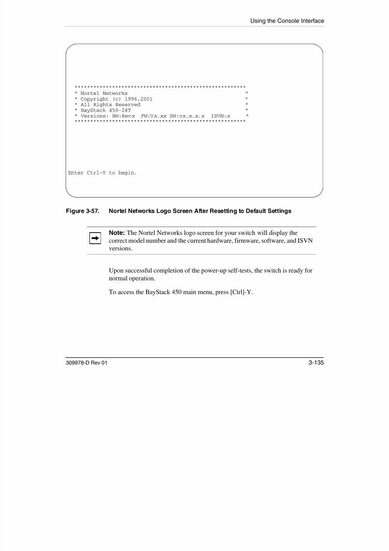
7/23/2019 Baystack 450
http://slidepdf.com/reader/full/baystack-450 295/399
309978-D Rev 01 3-135
To access the BayStack 450 main menu, press [Ctrl]-Y.
Using the BayStack 450 10/100/1000 Series Switch
LogoutThe Logout option (accessed from the main menu) allows you to terminate thesession from a password-protected console terminal or from an active TELNETsession.
The Logout option works as follows:
• If you are accessing the BayStack 450 switch through a TELNET session, theLogout option terminates the TELNET session.
• If you are accessing the BayStack 450 switch through a password-protectedconsole terminal (connected to the console/comm port on the switch), theLogout option displays the console-terminal password prompt (Figure 3-58).If RADIUS authentication is enabled, the Password field is preceded by aUsername field. You must enter the correct password (and username, if
applicable) to access the CI screens.
Figure 3-58. Password Prompt Screen
BayStack Model 450-24T HW:Revx FW:Vx .xx SW:Vx.x.x.x ISVN:x
Password: [ *************** ]
Enter Password:
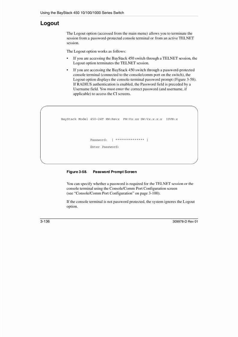
7/23/2019 Baystack 450
http://slidepdf.com/reader/full/baystack-450 296/399
3-136 309978-D Rev 01
You can specify whether a password is required for the TELNET session or theconsole terminal using the Console/Comm Port Configuration screen (see “Console/Comm Port Configuration” on page 3-100).
If the console terminal is not password protected, the system ignores the Logoutoption.
Chapter 4Troubleshooting
This chapter describes how to isolate and diagnose problems with your BayStack 450 switch.
This chapter covers the following topics:
• “Interpreting the LEDs” (page 4-1)• “Diagnosing and Correcting the Problem” (page 4-5)
• “Software Download Error Codes” (page 4-9)
The chapter topics lead you through a logical process for troubleshooting theBayStack 450 switch. For example, because LEDs provide visual indications of certain problems, refer to “Interpreting the LEDs” on page 4-1 to understand thevarious states (see Table 4-1) that your switch LEDs can exhibit during normaloperation.
For more help in determining the problem, “Diagnosing and Correcting theProblem” on page 4-5 describes symptoms and corrective actions (see Table 4-2)you can perform to resolve specific problems Subsequent sections give
Note: The LED Display panel configuration for your switch may be differentthan shown in this section, depending on the date of manufacturing (see thenote in “10BASE-T/100BASE-TX Ports” on page 1-4).

7/23/2019 Baystack 450
http://slidepdf.com/reader/full/baystack-450 297/399
309978-D Rev 01 4-1
you can perform to resolve specific problems. Subsequent sections givestep-by-step procedures to correct the problems.
Interpreting the LEDs
Figure 4-1 shows the BayStack 450-24T and BayStack 450-12T LED displaypanels. Figure 4-2 shows the BayStack 450-12F LED display panel.
Using the BayStack 450 10/100/1000 Series Switch
Table 4-1 describes the LEDs.
Figure 4-1. BayStack 450-24T/12T LED Display Panels
450-12T Switch
450-24T SwitchBayStack
Status Dwn
Pwr Up
1 53Cas
RPSUBase
BayStack
Activity
Activity
2119 2310/100
10/100
Activity
Activity
10/100
10/100
1713 15117 9
2 64 2220 241814 16128 10
BayStack 450-24T
BayStack 450-12T
BS45079A
1 53 117 9
2 64 128 10
Status Dwn
Pwr Up
Cas
RPSUBase

7/23/2019 Baystack 450
http://slidepdf.com/reader/full/baystack-450 298/399
4-2 309978-D Rev 01
Troubleshooting
Figure 4-2. BayStack 450-12F LED Display Panel
Table 4-1. BayStack 450 Switch LED Descriptions
Label Type Color State Meaning
Pwr Power status Green On DC power is available to the switch’s internal circuitry.
Off No AC power to switch, or power supply failed.
Status System status Green On Self-test passed successfully and switch is operational.
Blinking A nonfatal error occurred during the self-test.
Off The switch failed the self-test.
RPSU RPSU status Green On The switch is connected to the HRPSU and can receive
power if needed.
Off The switch is not connected to the HRPSU or HRPSU is
not supplying power.
Cas Up Stack mode Off The switch is in standalone mode.
Green On The switch is connected to the upstream unit’s Cascade A
BayStack 450-12F
BS45080A
450-12F SwitchBayStack
Status Dwn
Pwr Up 1 53
Cas
RPSUBaseActivity
Link
F Dx
117 92 64 128 10

7/23/2019 Baystack 450
http://slidepdf.com/reader/full/baystack-450 299/399
309978-D Rev 01 4-3
Green On The switch is connected to the upstream unit s Cascade A
In connector.
Yellow On The Cascade A Out connector (Cas Up) for this switch is
looped internally (wrapped to the secondary ring).
(continued)
Using the BayStack 450 10/100/1000 Series Switch
Yellow
or Green
Blinking Incompatible software revision or unable to obtain a unit
ID (Renumber Stack Unit table full). The unit is on the ring
but cannot participate in the stack configuration.
Cas Dwn Stack mode Off The switch is in standalone mode.
Green On The switch is connected to the downstream unit’s
Cascade A Out connector.
Yellow On The Cascade A In connector (Cas Dwn) for this switch is
looped internally (wrapped to the secondary ring).
Yellow
or Green
Blinking Incompatible software revision or unable to obtain a unit
ID (Renumber Stack Unit table full). The unit is on the ring
but cannot participate in the stack configuration.
Base Base mode Green On The switch is configured as the stack base unit.
Off The switch is not configured as the stack base unit (or is
in standalone mode).
Blinking Stack configuration error: Indicates that multiple base
units or no base units are configured in the stack.
Yellow On Indicates that this unit is operating as the stack
configuration’s temporary base unit . This condition occurs
automatically if the base unit (directly downstream from
this unit) fails.If this happens, the following events take place:
• The two units directly upstream and directly
downstream from the failed unit automatically wrap
their cascade connectors and indicate this condition
by lighting their Cas Up and Cas Dwn LEDs (see Cas
Up and Cas Dwn description in this table).
• If the temporary base unit fails, the next unit directly
downstream from this unit becomes the new
temporary base unit. This process can continue until
there are only two units left in the stack configuration.
Table 4-1. BayStack 450 Switch LED Descriptions (continued)
Label Type Color State Meaning

7/23/2019 Baystack 450
http://slidepdf.com/reader/full/baystack-450 300/399
4-4 309978-D Rev 01
This automatic failover is a temporary safeguard only. If
the stack configuration loses power, the temporary base
unit will not power up as the base unit when power is
restored. For this reason, you should always assign the
temporary base unit as the base unit (set the Unit Select
switch to Base) until the failed unit is repaired or replaced.
(continued)
Troubleshooting
Diagnosing and Correcting the Problem
Before you perform the problem-solving steps in this section, cycle the power tothe BayStack 450 switch (disconnect and then reconnect the AC power cord);
then, verify that the switch follows the normal power-up sequence.
10/100 10/100 Mb/s
port speed
indicator
Green On The corresponding port is set to operate at 100 Mb/s and
the link is good.
Green Blinking The corresponding port has been disabled by software.
Yellow On The corresponding port is set to operate at 10 Mb/s and
the link is good.
Yellow Blinking The corresponding port has been disabled by software.
Off The link connection is bad or there is no connection to
this port.
Link Link status Green On BayStack 450-12F model only: Valid communications link
established.
Off The communications link connection is bad or there is no
connection to this port.
Blinking The corresponding port is management disabled.
F Dx Duplex status Green On BayStack 450-12F model only: The corresponding port is
in full-duplex mode.
Off The corresponding port is in half-duplex mode
Activity Port activity Green or Yellow
Blinking Indicates network activity for the corresponding port. A
high level of network activity can cause the LEDs to
appear to be on continuously.
Warning: To avoid bodily injury from hazardous electrical current, neverremove the top cover of the device There are no user serviceable components
Table 4-1. BayStack 450 Switch LED Descriptions (continued)
Label Type Color State Meaning

7/23/2019 Baystack 450
http://slidepdf.com/reader/full/baystack-450 301/399
309978-D Rev 01 4-5
remove the top cover of the device. There are no user-serviceable componentsinside.
Vorsicht: Um Verletzungsgefahr durch einen elektrischen Stromschlag
auszuschließen, nehmen Sie niemals die obere Abdeckung vom Gerät ab. ImGeräteinnern befinden sich keine Komponenten, die vom Benutzer gewartetwerden können.
Using the BayStack 450 10/100/1000 Series Switch
Normal Power-Up Sequence
In a normal power-up sequence, the LEDs appear as follows:
1. After power is applied to the switch, the Pwr (Power) LED turns on within 5seconds.
2. The switch initiates a self-test, during which the port LEDs display variouspatterns to indicate the progress of the self-test.
3. Upon successful completion of the self-test (within 10 seconds after power isapplied), the Status LED turns on.
4. The remaining port LEDs indicate their operational status, as described inTable 4-2.
Avertissement: Pour éviter tout risque d'électrocution, ne jamais retirer lecapot de l'appareil. Cet appareil ne contient aucune pièce accessible parl'utilisateur.
Advertencia: A fin de evitar daños personales por corrientes eléctricaspeligrosas, no desmonte nunca la cubierta superior de este dispositivo. Loscomponentes internos no son reparables por el usuario.
Avvertenza: Per evitare lesioni fisiche dovute a scariche pericolose dicorrente, non rimuovere mai il coperchio superiore del dispositivo. Icomponenti interni non possono essere manipolati dall'utente.

7/23/2019 Baystack 450
http://slidepdf.com/reader/full/baystack-450 302/399
4-6 309978-D Rev 01
Troubleshooting
Table 4-2. Corrective Actions
Symptom Probable cause Corrective action
All LEDs are off. The switch is not receiving AC
power.
Verify that the AC power cord is fastened securely
at both ends and that power is available at the AC
power outlet.
The fans are not operating orthe airflow is blocked, causing
the unit to overheat.
Verify that there is sufficient space for adequateairflow on both sides of the switch.
Note: Operating temperature for the switch must
not exceed 40°C (104°F). Do not place the switch
in areas where it can be exposed to direct sunlight
or near warm air exhausts or heaters.
The Activity LED for aconnected port is off or
does not blink (and you
have reason to believe
that traffic is present).
The switch is experiencing aport connection problem. See the next section, “Port Connection Problems.”
The switch’s link partner is not
autonegotiating properly.
The Status LED is off. A fatal error was detected by
the self-test.
Cycle the power to the switch (disconnect and then
reconnect the AC power cord).
If the problem persists, replace the switch.
The Status LED is
blinking.
A nonfatal error occurred
during the self-test.
Cycle the power to the switch (disconnect and then
reconnect the AC power cord).
If the problem persists, contact the Nortel
Networks Technical Solutions Center.
When connecting a
console/terminal to an
operating switch
through the switch’sserial Comm Port, the
console/terminal
displays a blank
screen
This is a normal condition. Press [Ctrl]-C to refresh the screen.

7/23/2019 Baystack 450
http://slidepdf.com/reader/full/baystack-450 303/399
309978-D Rev 01 4-7
screen.
Using the BayStack 450 10/100/1000 Series Switch
Port Connection Problems
You can usually trace port connection problems to either a poor cable connectionor an improper connection of the port cables at either end of the link. To remedythese types of problems, make sure that the cable connections are secure and thatthe cables connect to the correct ports at both ends of the link.
Port connection problems are also traceable to the autonegotiation mode or the
port interface.
Autonegotiation Modes
Port connection problems can occur when a port (or station) is connected toanother port (or station) that is not operating in a compatible mode (for example,connecting a full-duplex port on one station to a half-duplex port on anotherstation).
The BayStack 450 switch negotiates port speeds according to the IEEE 802.3uautonegotiating standard. The switch adjusts (autonegotiates) its port speed andduplex mode to match the best service provided by the connected station, up to100 Mb/s in full-duplex mode.
• If the connected station uses a form of autonegotiation that is not compatiblewith the IEEE 802.3u autonegotiating standard, the BayStack 450 switch
cannot negotiate a compatible mode for correct operation.
• If the autonegotiation feature is not present or not enabled at the connectedstation, the BayStack 450 switch may not be able to determine the correctduplex mode.
In both situations, the BayStack 450 switch “autosenses” the speed of theconnected station and, by default, reverts to half-duplex mode. If the connected
station is operating in full-duplex mode, it cannot communicate with the switch.
To correct this mode mismatch problem:
1 Use the Port Configuration screen to disable autonegotiation for the

7/23/2019 Baystack 450
http://slidepdf.com/reader/full/baystack-450 304/399
4-8 309978-D Rev 01
1. Use the Port Configuration screen to disable autonegotiation for the
suspect port (see “Port Configuration” on page 3-59).
2. Manually set the Speed/Duplex field to match the speed/duplex mode of
the connected station (see Table 3-20 on page 3-61).
You may have to try several settings before you find the correct speed/duplexmode of the connected station.
Troubleshooting
If the problem persists:
1. Disable the autonegotiation feature at the connected station.
2. Manually set the speed/duplex mode of the connected station to the same
speed/duplex mode you have manually set for the BayStack 450 switch
port.
Port Interface
Ensure that the devices are connected using the appropriate crossover orstraight-through cable (see Appendix F, “Connectors and Pin Assignments”).
Software Download Error Codes
Table 4-3 describes error codes that are associated with the software downloadprocess. The error codes appear only on the console screen of the switch that isconnected to your TFTP load host during the software download process.
If an error code appears during the download process, perform the appropriate
corrective action provided in Table 4-3. If the suggested corrective action does notresolve the problem, contact your Nortel Networks Technical Solutions Center(see “How to Get Help” in the Preface section of this guide).
Note: Nortel Networks recommends that you manually set the BayStack 450switch port to the desired speed/duplex mode when connecting to any of thefollowing Nortel Networks products:
• Nortel Networks 28000 product family
• Nortel Networks 58000 product family
• BayStack Model 302T switch (100 Mb/s port)
7/23/2019 Baystack 450
http://slidepdf.com/reader/full/baystack-450 305/399
309978-D Rev 01 4-9
Using the BayStack 450 10/100/1000 Series Switch
Table 4-3. Software Download Error Codes
Error code Description Corrective action
2001 Download process failed to transmit
packet to other stack units.
Check the stack cable connections, and then
repeat the software download process.
2002 TFTP load host failed to respond to ARP
request.
Verify that your TFTP load host is operational
and check that the connectivity between theswitch/stack and the TFTP load host is valid.
2003 Received image failed CRC check. Verify that the switch software image is valid (not
corrupted) and repeat the software download
process.
2004 The download process has lost
synchronization with the TFTP load
host.
Verify that your TFTP load host is operational,
and then repeat the software download process.
2005 TFTP timeout. The software download
has timed out due to network congestion
or the load host has stopped
responding.
Verify that your TFTP load host is operational,
and then repeat the software download process.
2006 File access error. Check that the file name of the software image is
correct, and that the file protection is properly
set for access.
2007 Non-data packet received from theTFTP load host.
Check that the file name of the software image iscorrect.
2008 Requested software image is too large. Check that the file name of the software image is
correct, and that you are accessing the
appropriate software image for your switch.
2009 Received image failed CRC check. Verify that the switch software image is valid (not
corrupted) and repeat the software download
process.
2010 No MAC address found in EEPROM. Contact the Nortel Networks Technical Solutions
Center.

7/23/2019 Baystack 450
http://slidepdf.com/reader/full/baystack-450 306/399
4-10 309978-D Rev 01
Appendix ATechnical Specifications
This appendix lists the technical specifications for the BayStack 450 10/100/1000Series Switches.
This appendix covers the following topics:
• “Environmental” (page A-1)• “Electrical” (page A-2)
• “Physical Dimensions” (page A-2)
• “Performance Specifications” (page A-2)
• “Network Protocol and Standards Compatibility” (page A-3)
• “Data Rate” (page A-3)• “Interface Options” (page A-3)
• “Safety Agency Certification” (page A-4)
• “Electromagnetic Emissions” (page A-4)
• “Electromagnetic Immunity” (page A-4)
• “Declaration of Conformity” (page A-4)
Environmental

7/23/2019 Baystack 450
http://slidepdf.com/reader/full/baystack-450 307/399
309978-D Rev 01 A-1
Parameter Operating Specification Storage Specification
Temperature 0° to 40°C (32° to 104°F) -25° to 70°C (-13° to 158°F)
Humidity 85% maximum relative humidity,noncondensing
95% maximum relative humidity,noncondensing
Altitude 3024 m (10,000 ft) 3024 m (10,000 ft)
Using the BayStack 450 10/100/1000 Series Switch
Electrical
Physical Dimensions
Performance Specifications
Parameter Model 450-24T Model 450-12T/12F
Input Voltage 100 to 240 VAC @ 50 to 60 Hz 100 to 240 VAC @ 50 to 60 Hz
Input Power
Consumption
150 W maximum 120 W maximum
Input Volt Amperes
Rating
200 VA maximum 150 VA maximum
Input Current 2.0 A @ 100 VAC 1.5 A @ 100 VAC
Maximum Thermal
Output
500 BTU/hr 400 BTU/hr
Parameter Specifications
Height 7.03 cm (2.77 in.)
Width 44.07 cm (17.55 in.)
Depth 38.1 cm (15.0 in.)
Weight 5.26 kg (11.60 lb)
Parameter Specifications
Frame Forward Rate
(64-byte packets)
Up to 3 million packets per second (pps) maximum, learned
unicast traffic
Port Forwarding/ Filtering Performance (64-byte packets)
• For 10 Mb/s: 14,880 pps maximum• For 100 Mb/s: 148,810 pps maximum
• For 1000 Mb/s: 1,488,100 pps maximum
• For ATM: 350,000 pps per port maximum (total
bidirectional)

7/23/2019 Baystack 450
http://slidepdf.com/reader/full/baystack-450 308/399
A-2 309978-D Rev 01
)
Address Database Size 16,000 entries at line rate (32,000 entries without flooding)
Addressing 48-bit MAC address
Frame Length 64 to 1518 bytes (IEEE 802.1Q Untagged)64 to 1522 bytes (IEEE 802.1Q Tagged)

7/23/2019 Baystack 450
http://slidepdf.com/reader/full/baystack-450 309/399
Using the BayStack 450 10/100/1000 Series Switch
Safety Agency Certification
Electromagnetic Emissions
Electromagnetic Immunity
Declaration of Conformity
The Declaration of Conformity for the BayStack 450 switches complies with ISO/ IEC Guide 22 and EN45014. The declaration identifies the product models, theNortel Networks name and address, and the specifications recognized by theEuropean community.
• UL Listed (UL 1950)
• IEC 950/EN60950
• C22.2 No. 950 (cUL)
• UL-94-V1 flammability requirements for PC board
• US. CFR47, Part 15, Subpart B, Class A
• Canada. ICES-003, Issue 2, Class A
• Australia/New Zealand. AS/NZS 3548:1995, Class A
• Japan. V-3/97.04:1997, Class A• Taiwan. CNS 13438, Class A
• EN55022:1995, Class A
• EN61000-3-2:1995
• EN61000-3-3:1994
• EN50082-1:1997

7/23/2019 Baystack 450
http://slidepdf.com/reader/full/baystack-450 310/399
A-4 309978-D Rev 01
As stated in the Declaration of Conformity, the BayStack 450 switches complywith the provisions of Council Directives 89/336/EEC and 73/23/EEC.
Appendix BGigabit Fiber Optical Characteristics
The Uplink/Expansion Module on the BayStack 450 switch supports1000BASE-X (Gigabit Ethernet) MDAs. This appendix describes the opticalcharacteristics of the 1000BASE-X MDAs. See Appendix C, “Media DependentAdapters,” for more information about MDAs.
This appendix covers the following topics:
• “1000BASE-SX Models” (page B-1)
• “1000BASE-LX Models” (page B-4)
1000BASE-SX Models
The 450-1SX and 450-1SR MDAs provide 1000BASE-SX (850 nanometers, shortwavelength, Gigabit Ethernet) connectivity. The 450-1SX provides one1000BASE-SX port. The 450-1SR provides one 1000BASE-SX port and oneLinkSafe redundant port.
Operating Range
Table B-1 lists the operating range for the 1000BASE-SX models:
Table B-1. Operating Range for 1000BASE-SX
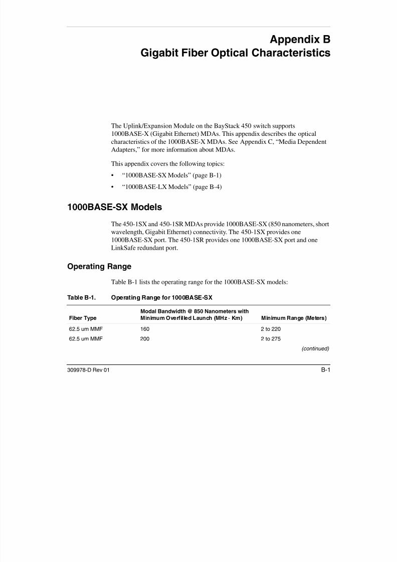
7/23/2019 Baystack 450
http://slidepdf.com/reader/full/baystack-450 311/399
309978-D Rev 01 B-1
Fiber Type
Modal Bandwidth @ 850 Nanometers with
Minimum Overfilled Launch (MHz · Km) Minimum Range (Meters)
62.5 um MMF 160 2 to 220
62.5 um MMF 200 2 to 275
(continued)
Using the BayStack 450 10/100/1000 Series Switch
Transmit Characteristics
Table B-2 lists the transmit characteristics for the 1000BASE-SX models:
50 um MMF 400 2 to 500
50 um MMF 500 2 to 550
10 um MMF Not supported Not supported
Table B-2. 100BASE-SX Transmit Characteristics
Description
62.5 Micron Multimode Fiber
50 Micron Multimode Fiber Units
Transmitter type Shortwave Laser Shortwave Laser
Signaling speed 1.25 ± 100 ppm 1.25 ± 100 ppm GBd
Wavelength (l, range) 770 to 860 770 to 860 nm
T rise/T fall (maximum; 20% - 80%; > 830 nm) 0.26 0.26 ns
T rise/T fall (maximum; 20% - 80%; <= 830 nm) 0.21 0.21 ns
RMS spectral width (maximum) 0.85 0.85 nm
Average launch power (maximum)*
* The 1000BASE-SX launch power shall be the lesser of the class 1 safety limit, as defined by the IEEE 802.3z standard,
Clause 38.7.2, or the average receive power (maximum), as defined in Table B-3.
See footnote 1 See footnote 1 dBm
Average launch power (minimum) -9.5 -9.5 dBm
Average launch power of OFF transmitter
(maximum)†
† Examples of an OFF transmitter are: no power supplied to the PMD laser shutdown for safety conditions activation of a
-30 -30 dBm
Extinction ratio (minimum) 9 9 dB
RIN (maximum) -117 -117 dB/HzCoupled Power Ration (CPR) minimum ‡ 9 < CPR 9 < CPR dB
Table B-1. Operating Range for 1000BASE-SX (continued)
Fiber Type
Modal Bandwidth @ 850 Nanometers with
Minimum Overfilled Launch (MHz · Km) Minimum Range (Meters)

7/23/2019 Baystack 450
http://slidepdf.com/reader/full/baystack-450 312/399
B-2 309978-D Rev 01
† Examples of an OFF transmitter are: no power supplied to the PMD, laser shutdown for safety conditions, activation of a
“transmit disable” or other optional laser shutdown conditions. During all conditions when the PMA is powered, the AC
signal (data) into the transmit port will be valid encoded 8B/10B patterns (this is a requirement of the PCS layers), except
for short durations during system power-on-reset or diagnostics when the PMA is placed in a loopback mode.
‡ Avoid radial overfilled launches even if the launch parameters are within the CPR range.
Gigabit Fiber Optical Characteristics
Receive Characteristics
Table B-3 lists the receive characteristics for the 1000BASE-SX models:
Worst-Case Power Budget and Penalties
Table B-4 lists the worst-case power budget and penalties for the 1000BASE-SXmodels:
Table B-3. 1000BASE-SX Receive Characteristics
Description62.5 MicronMultimode Fiber
50 MicronMultimode Fiber Units
Signaling Speed (range) 1.25 ± 100 ppm 1.25 ± 100 ppm GBdWavelength (range) 770 to 860 770 to 860 nm
Average receive power (maximum) 0 0 dBm
Receive sensitivity – 17 – 17 dBm
Return loss (minimum) 12 12 dB
Stressed receive sensitivity *, †
* Measured with conformance test signal at TP3 for BER = 10–12 at the eye center.
† Measured with a transmit signal having a 9 dB extinction ratio. If you use another extinction ratio, correct the stressed
receive sensitivity according to the extinction ratio penalty.
– 12.5 – 13.5 dBm
Receive electrical 3 dB upper cutoff frequency(maximum)
1500 1500 MHz
Vertical eye-closure penalty ‡
‡ Vertical eye-closure penalty is a test condition for measuring stressed receive sensitivity. It is not a required
characteristic of the receiver.
2.60 2.20 dB
Note: The link power penalties (Table B-4) are used for link power budgetcalculations only. They are not requirements and are not meant to be tested.

7/23/2019 Baystack 450
http://slidepdf.com/reader/full/baystack-450 313/399
309978-D Rev 01 B-3
Using the BayStack 450 10/100/1000 Series Switch
1000BASE-LX Models
The 450-1LX and 450-1LR MDAs provide 1000BASE-LX (1300 nanometers,long wavelength, Gigabit Ethernet) connectivity. The 450-1LX provides one1000BASE-LX port. The 450-1LR provides one 1000BASE-LX port and oneLinkSafe redundant port.
Operating Range
Table B-5 lists the operating range for the 1000BASE-LX models:
Table B-4. Worst-Case 1000BASE-SX Power Budget and Penalties
Parameter
62.5 Micron
Multimode Fiber
50 Micron
Multimode Fiber Units
Modal bandwidth as measured at 850 nm
(minimum, overfilled launch)
160 200 400 500 MHz · km
Link power budget 7.5 7.5 7.5 7.5 dB
Operating distance 220 275 500 550 m
Channel insertion loss *, † 2.38 2.60 3.37 3.56 dB
Link power penalties 4.27 4.29 4.07 3.57 dB
Unallocated margin in link power budget 0.84 0.60 0.05 0.37 dB
* Operating distances used to calculate the channel insertion loss are the maximum values specified in Table B-1 on
page B-1.
† A wavelength of 830 nm is used to calculate channel insertion loss, link power penalties, and unallocated margin.
Table B-5. Operating Range for 1000BASE-LX
Fiber Type Modal Bandwidth @ 1300 Nanometers withMinimum Overfilled Launch (MHz · km) Minimum Range (Meters)
62.5 um MMF 500 2 to 550
50 um MMF 400 2 to 550
50 um MMF 500 2 to 550

7/23/2019 Baystack 450
http://slidepdf.com/reader/full/baystack-450 314/399
B-4 309978-D Rev 01
50 um MMF 500 2 to 550
10 um SMF N/A 2 to 5000
Gigabit Fiber Optical Characteristics
Transmit Characteristics
Table B-6 lists the transmit characteristics for the 1000BASE-LX models:
Receive Characteristics
Table B-7 lists the receive characteristics for the 1000BASE-LX models:
Table B-6. 1000BASE-LX Transmit Characteristics
Description
62.5 Micron
Multimode Fiber
50 Micron
Multimode Fiber
10 MicronSingle-Mode
Fiber Unit
Transmitter type Longwave Laser Longwave Laser Longwave Laser
Signaling speed (range) 1.25 ± 100 ppm 1.25 ± 100 ppm 1.25 ± 100 ppm GBd
Wavelength (range) 1270 to 1355 1270 to 1355 1270 to 1355 nm
T rise /T fall (maximum 20-80% response time)
0.26 0.26 0.26 ns
RMS spectral width (maximum) 4 4 4 nm
Average launch power (maximum) – 3 – 3 – 3 dBm
Average launch power (minimum) – 11.5 – 11.5 – 11.0 dBm
Average launch power of OFF
transmitter (maximum)
– 30 – 30 – 30 dBm
Extinction ratio (minimum) 9 9 9 dB
RIN (maximum) – 120 – 120 – 120 dB/Hz
Coupled Power Ratio (CPR)*
* Due to the dual media (single-mode and multimode) support of the LX transmitter, fulfillment of this specification requires
a single-mode fiber offset-launch mode-conditioning patch cord described in IEEE 802.3, Clause 38.11.4 for MMF
operation. This patch cord is not used for single-mode operation.
28 < CPR < 40 12 < CPR < 20 N/A dB
Table B-7. 1000BASE-LX Receive Characteristics
Description Value Units

7/23/2019 Baystack 450
http://slidepdf.com/reader/full/baystack-450 315/399
309978-D Rev 01 B-5
Signaling speed (range) 1.25 ± 100 ppm GBd
Wavelength (range) 1270 to 1355 nm
Average receive power (maximum) – 3 dBm
(continued)
Using the BayStack 450 10/100/1000 Series Switch
Worst-Case Power Budget and Penalties
Table B-8 lists the worst-case power budget and penalties for the 1000BASE-LXmodels:
Receive sensitivity – 19 dBm
Return loss (minimum) 12 dB
Stressed receive sensitivity *, † – 14.4 dBm
Receive electrical 3 dB upper cutoff frequency (maximum) 1500 MHz
Vertical eye-closure penalty ‡ 2.60 dB* Measured with conformance test signal at TP3 (see IEEE 802.3, Clause 38.6.11) for BER = 10–12 at the eye center.
† Measured with a transmit signal having a 9 dB extinction ratio. If another extinction ratio is used, the stressed receive
sensitivity should be corrected for the extinction ratio penalty.
‡ Vertical eye-closure penalty is a test condition for measuring stressed receive sensitivity. It is not a required
characteristic of the receiver.
Note: The link power penalties (Table B-8) are used for link power budgetcalculations only. They are not requirements and are not meant to be tested.
Table B-8. Worst-Case 1000BASE-LX Power Budget and Penalties
Parameter 62.5 um MMF 50 um MMF 10 um SMF Unit
Modal bandwidth as measured at
1300 nm (minimum, overfilled launch)
500 400 500 N/A MHz · km
Link power budget 7.5 7.5 7.5 8.0 dBOperating distance 550 550 550 5000 m
Channel insertion loss 2.35 2.35 2.35 4.57 dB
Link power penalties 3.48 5.08 3.96 3.27 dB
Unallocated margin in link power budget 1 67 0 07 1 19 0 16 dB
Table B-7. 1000BASE-LX Receive Characteristics (continued)
Description Value Units

7/23/2019 Baystack 450
http://slidepdf.com/reader/full/baystack-450 316/399
B-6 309978-D Rev 01
Unallocated margin in link power budget 1.67 0.07 1.19 0.16 dB
Appendix C
Media Dependent Adapters
This appendix describes the optional media dependent adapters (MDAs) that aresupported by your switch. The MDAs can support high-speed connections toservers, shared Fast Ethernet hubs, or backbone devices.
Your BayStack 450 switch supports the following MDAs:
Note: The MDAs are not hot-swappable. Power down the switch beforeinstalling or removing an MDA.
Interface type Model Refer to:
10BASE-T/100BASE-TX (UTP) 400-4TX MDA page C-2
100BASE-FX (Multimode fiber) 400-2FX MDA
400-4FX MDA
page C-3
1000BASE-SX (Shortwave gigabit fiber)
450-1SR MDA
450-1SX MDA
page C-6
1000BASE-LX (Longwave gigabit fiber)
450-1LR MDA
450-1LX MDA
page C-9
Asynchronous Transfer Mode (ATM) 450-2M3 MDA
450-2S3 MDA
page C-12
Gigabit Interface Converter (GBIC) 450-1GBIC MDA page C-15

7/23/2019 Baystack 450
http://slidepdf.com/reader/full/baystack-450 317/399
309978-D Rev 01 C-1
Nortel Networks is constantly adding new models and features to existing productlines. For a full range of MDAs that are available from Nortel Networks, see your
Nortel Networks sales representative.
Using the BayStack 450 10/100/1000 Series Switch
10BASE-T/100BASE-TX MDA
The 400-4TX MDA (Figure C-1) uses four 10BASE-T/100BASE-TX RJ-45(8-pin modular) port connectors to attach Ethernet devices. Table C-1 describesthe 400-4TX MDA components and LEDs.
Figure C-1. 400-4TX MDA Front Panel
Table C-1. 400-4TX MDA Components
Item Label Description
1 100 100BASE-TX port status LEDs (green):
On: The corresponding port is set to operate at 100 Mb/s.Off: The link connection is bad or there is no connection to this port.
Blinking: The corresponding port is management disabled.
2 10 10BASE-T port status LEDs (green):
On: The corresponding port is set to operate at 10 Mb/s.
Off: The link connection is bad or there is no connection to this port.
Blinking: The corresponding port is management disabled.3 F Dx Full-duplex port status LEDs (green):
On: The corresponding port is in full-duplex mode.
Off: The corresponding port is in half-duplex mode.
4 Activity Port activity LEDs (green):
400-4TX MDA
Activity
100
10
F Dx
1
4
BS45042A
5 3
2

7/23/2019 Baystack 450
http://slidepdf.com/reader/full/baystack-450 318/399
C-2 309978-D Rev 01
4 Activity Port activity LEDs (green):
Blinking: Indicates the network activity level for the corresponding port. A
high level of network activity can cause LEDs to appear to be on
continuously.
5 10BASE-T/100BASE-TX RJ-45 (8-pin modular) port connectors.
Media Dependent Adapters
The RJ-45 ports are configured as media-dependent interface-crossover (MDI-X)
connectors. These ports connect over straight cables to the network interfacecontroller (NIC) card in a node or server, similar to a conventional Ethernetrepeater hub. If you are connecting to another Ethernet hub or Ethernet switch,you need a crossover cable unless an MDI connection exists on the associated portof the attached device.
The 400-4TX MDA can operate at either 10 Mb/s or 100 Mb/s. The speed isdetermined through autonegotiation with its connecting device.
For installation instructions, see “Installing an MDA” on page C-17.
100BASE-FX MDAs
Warning: Fiber optic equipment can emit laser or infrared light that can
injure your eyes. Never look into an optical fiber or connector port. Alwaysassume that fiber optic cables are connected to a light source.
Vorsicht: Glasfaserkomponenten können Laserlicht bzw. Infrarotlichtabstrahlen, wodurch Ihre Augen geschädigt werden können. Schauen Sieniemals in einen Glasfaser-LWL oder ein Anschlußteil. Gehen Sie stetsdavon aus, daß das Glasfaserkabel an eine Lichtquelle angeschlossen ist.
Avertissement: L’équipement à fibre optique peut émettre des rayonslaser ou infrarouges qui risquent d’entraîner des lésions oculaires. Ne jamais regarder dans le port d’un connecteur ou d’un câble à fibre optique.Toujours supposer que les câbles à fibre optique sont raccordés à unesource lumineuse.
Advertencia: Los equipos de fibra óptica pueden emitir radiaciones deláser o infrarrojas que pueden dañar los ojos. No mire nunca en el interiorde una fibra óptica ni de un puerto de conexión. Suponga siempre que loscables de fibra óptica están conectados a una fuente luminosa.
Avvertenza: Le apparecchiature a fibre ottiche emettono raggi laser o
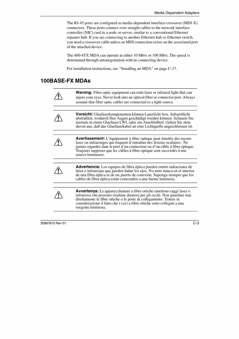
7/23/2019 Baystack 450
http://slidepdf.com/reader/full/baystack-450 319/399
309978-D Rev 01 C-3
Avvertenza: Le apparecchiature a fibre ottiche emettono raggi laser oinfrarossi che possono risultare dannosi per gli occhi. Non guardare maidirettamente le fibre ottiche o le porte di collegamento. Tenere inconsiderazione il fatto che i cavi a fibre ottiche sono collegati a unasorgente luminosa.
Using the BayStack 450 10/100/1000 Series Switch
There are two 100BASE-FX models (Figure C-2):
• 400-2FX MDA
The 400-2FX MDA uses two longwave 1300 nm SC connectors to attach
devices over 62.5/125- or 50/125-micron multimode fiber optic cable.• 400-4FX MDA
The 400-4FX MDA uses four longwave 1300 nm MT-RJ connectors to attachdevices over 62.5/125- or 50/125-micron multimode fiber optic cable.
Figure C-2. 100BASE-FX MDA Front Panels
Both models conform to the IEEE 802.3u 100BASE-FX standard and can be usedf fib b d 100 Mb/ i (2 k /1 2 i i di ) h
RXTX
100BASE-FX
RXTX
100BASE-FX
Activity
Link
F Dx
400-2FX MDA
BS45043A
34
21
Activity
Link
F Dx
400-4FX MDA
34
2
1

7/23/2019 Baystack 450
http://slidepdf.com/reader/full/baystack-450 320/399
C-4 309978-D Rev 01
for fiber-based 100 Mb/s connections (2 km/1.2 mi maximum distance) to othercompatible Fast Ethernet devices. Single-mode fiber cable is not supported.
Table C-2 describes the 100BASE-FX components and LEDs.
Media Dependent Adapters
For installation instructions, see “Installing an MDA” on page C-17.
Table C-2. 100BASE-FX MDA Components
Item Label Description
1 Link Communications link LEDs (green):
On: Valid communications link established.
Off: The communications link connection is bad or there is no connection to this
port.
Blinking: The corresponding port is management disabled.
2 F Dx Full-duplex port status LEDs (green):
On: The corresponding port is in full-duplex mode.
Off: The corresponding port is in half-duplex mode.
3 Activity Port activity LEDs (green):
Blinking: Indicates the network activity level for the corresponding port. A highlevel of network activity can cause LEDs to appear to be on continuously.
4 100BASE-FX port connectors:
• Model 400-2FX uses SC connectors.
• Model 400-4FX uses MT-RJ connectors.

7/23/2019 Baystack 450
http://slidepdf.com/reader/full/baystack-450 321/399
309978-D Rev 01 C-5
Using the BayStack 450 10/100/1000 Series Switch
1000BASE-SX MDAs
Warning: This is a Class 1 Laser/LED product. It contains a laser lightsource that can injure your eyes. Never look into an optical fiber orconnector port. Always assume that the fiber optic cable or connector isconnected to a laser light source.
Vorsicht: Dieses Laser/LED-Produkt der Klasse 1 enthält eineLaserlichtquelle, die zu Augenverletzungen führen kann. Sehen Sie nie ineinen Lichtwellenleiter oder Glasfaserstecker-Port. Gehen Sie immerdavon aus, daß das Glasfaserkabel oder der Glasfaserstecker an eineLaserlichtquelle angeschlossen ist.
Avertissement: Ceci est un appareil Laser/DEL de Classe 1. Cetappareil contient une source lumineuse à rayons laser dangereuse pour les
yeux. Ne regardez jamais directement une fibre optique ou un port deconnexion. Agissez toujours comme si le câble de fibres optiques ou leconnecteur était relié à une source lumineuse à rayons laser.
Advertencia: Éste es un producto láser/LED de Clase 1. Contiene unafuente de luz láser que puede causar lesiones en los ojos. Nunca miredentro de un cable o de un puerto de conexión de fibra óptica. Asumasiempre que el cable o el connector de fibra óptica está conectado a unafuerte de luz láser.
Avvertenza: Questo è un produtto laser/LED di Classe 1 e contiene unasorgente luminosa a laser che può danneggiare gli occhi. Non guardaremai all’interno di una port a fibra ottica o di una porta connettore. Daresempre per scontato che il cavo di fibra ottica o il connettore sianocollegati ad una sorgente luminosa a laser.

7/23/2019 Baystack 450
http://slidepdf.com/reader/full/baystack-450 322/399
C-6 309978-D Rev 01
Media Dependent Adapters
There are two 1000BASE-SX (shortwave gigabit) MDA models (Figure C-3):
• The 450-1SR MDA is a single MAC MDA with a separate redundant Phy(backup Phy port). Only one Phy port can be active at any time. If the activePhy port fails, the redundant Phy port automatically becomes the active port.
• The 450-1SX MDA is a single PHY MDA.
Both models conform to the IEEE 802.3z 1000BASE-SX standard and useshortwave 850 nm fiber optic connectors to connect devices over multimode (550
meter/1,805 ft) fiber optic cable.
Figure C-3. 1000BASE-SX MDA Front Panels
Table C-3 describes the 1000BASE-SX components and LEDs.
For installation instructions, see “Installing an MDA” on page C-17.
1000BASE-SX
TX RX
Phy
Link
Activity
450-1SX MDA
TXRX
1000BASE-SX
RX
1000BASE-SX
TX
Activity
Link
Phy Select
450-1SR MDA
3
BS45044A
4
34
450-1SR MDA
(1-port redundant)
450-1SX MDA
(single port)
21
21

7/23/2019 Baystack 450
http://slidepdf.com/reader/full/baystack-450 323/399
309978-D Rev 01 C-7
Using the BayStack 450 10/100/1000 Series Switch
Table C-3. 1000BASE-SX MDA Components
Item Label Description
1 Link Communication link LEDs (green):
On: Valid communications link.
Off: The communications link connection is bad or there is no connection to
this port.
Blinking: The corresponding port is management disabled.
2 Phy or Phy status LEDs (green):
Phy Select On: The corresponding Phy port is active.
Off: The corresponding Phy port is in backup mode or there is no
connection to this port.
3 Activity Port activity LEDs (green):Blinking: Indicates network activity level for the corresponding port. A high
level of network activity can cause LEDs to appear to be on continuously.
4 1000BASE-X SC port connectors.

7/23/2019 Baystack 450
http://slidepdf.com/reader/full/baystack-450 324/399
C-8 309978-D Rev 01
Media Dependent Adapters
1000BASE-LX MDAs
Warning: This is a Class 1 Laser/LED product. It contains a laser lightsource that can injure your eyes. Never look into an optical fiber orconnector port. Always assume that the fiber optic cable or connector isconnected to a laser light source.
Vorsicht: Dieses Laser/LED-Produkt der Klasse 1 enthält eineLaserlichtquelle, die zu Augenverletzungen führen kann. Sehen Sie nie ineinen Lichtwellenleiter oder Glasfaserstecker-Port. Gehen Sie immerdavon aus, daß das Glasfaserkabel oder der Glasfaserstecker an eineLaserlichtquelle angeschlossen ist.
Avertissement: Ceci est un appareil Laser/DEL de Classe 1. Cetappareil contient une source lumineuse à rayons laser dangereuse pour les
yeux. Ne regardez jamais directement une fibre optique ou un port deconnexion. Agissez toujours comme si le câble de fibres optiques ou leconnecteur était relié à une source lumineuse à rayons laser.
Advertencia: Éste es un producto láser/LED de Clase 1. Contiene unafuente de luz láser que puede causar lesiones en los ojos. Nunca miredentro de un cable o de un puerto de conexión de fibra óptica. Asumasiempre que el cable o el connector de fibra óptica está conectado a unafuerte de luz láser.
Avvertenza: Questo è un produtto laser/LED di Classe 1 e contiene unasorgente luminosa a laser che può danneggiare gli occhi. Non guardaremai all’interno di una port a fibra ottica o di una porta connettore. Daresempre per scontato che il cavo di fibra ottica o il connettore siano collegatiad una sorgente luminosa a laser.
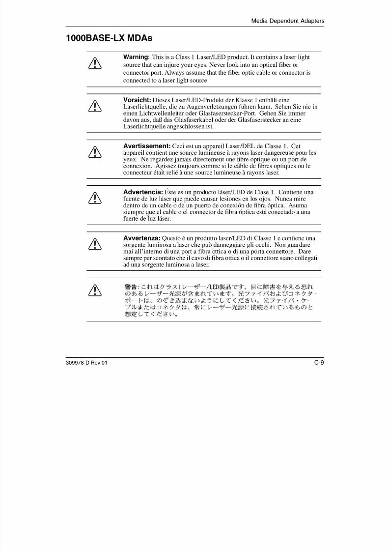
7/23/2019 Baystack 450
http://slidepdf.com/reader/full/baystack-450 325/399
309978-D Rev 01 C-9
Using the BayStack 450 10/100/1000 Series Switch
There are two 1000BASE-LX (longwave gigabit) MDA models (Figure C-4):
• The 450-1LR MDA is a single MAC MDA with a separate redundant Phy(backup Phy port). Only one Phy port can be active at any time. If the activePhy port fails, the redundant Phy port automatically becomes the active port.
• The 450-1LX MDA is a single Phy MDA.
Both models conform to the IEEE 802.3z 1000BASE-LX standard and uselongwave 1300 nm fiber optic connectors to connect devices over single mode (5 kilometer/3.1 mi) or multimode (550 meter/1,805 ft) fiber optic cable.
Figure C-4. 1000BASE-LX MDA Front Panels
Note: The optical performance of this transceiver cannot be guaranteed whenconnected to a multimode fiber plant without the use of the special offset SMF/ MMF mode conditioning patch cord (see “1000BASE-LX MultimodeApplications” on page C-22).
1000BASE-LX
TX RX
Phy
Link
Activity
450-1LX MDA
BS45045A
34
21
TXRX
1000BASE-LX
RX
1000BASE-LX
TX
Activity
Link
Phy Select
450-1LR MDA
34
21450-1LR MDA
(1-port redundant)
450-1LX MDA
(single port)

7/23/2019 Baystack 450
http://slidepdf.com/reader/full/baystack-450 326/399
C-10 309978-D Rev 01
Table C-4 describes the 1000BASE-LX MDA components and LEDs.
Media Dependent Adapters
For installation instructions, see “Installing an MDA” on page C-17.
Table C-4. 1000BASE-LX MDA Components
Item Label Description
1 Link Communication link LEDs (green):
On: Valid communications link.
Off: The communications link connection is bad or there is no connection to
this port.
Blinking: The corresponding port is management disabled.
2 Phy or Phy status LEDs (green):
Phy Select On: The corresponding Phy port is active.
Off: The corresponding Phy port is in backup mode or there is no
connection to this port.
3 Activity Port activity LEDs (green):Blinking: Indicates network activity level for the corresponding port. A high
level of network activity can cause LEDs to appear to be on continuously.
4 1000BASE-X SC port connectors (see “1000BASE-LX Multimode Applications”
on page C-22 for special requirements).

7/23/2019 Baystack 450
http://slidepdf.com/reader/full/baystack-450 327/399
309978-D Rev 01 C-11
Using the BayStack 450 10/100/1000 Series Switch
Asynchronous Transfer Mode (ATM) MDAs
Warning: This is a Class 1 Laser/LED product. It contains a laser lightsource that can injure your eyes. Never look into an optical fiber orconnector port. Always assume that the fiber optic cable or connector isconnected to a laser light source.
Vorsicht: Dieses Laser/LED-Produkt der Klasse 1 enthält eineLaserlichtquelle, die zu Augenverletzungen führen kann. Sehen Sie nie ineinen Lichtwellenleiter oder Glasfaserstecker-Port. Gehen Sie immerdavon aus, daß das Glasfaserkabel oder der Glasfaserstecker an eineLaserlichtquelle angeschlossen ist.
Avertissement: Ceci est un appareil Laser/DEL de Classe 1. Cetappareil contient une source lumineuse à rayons laser dangereuse pour les
yeux. Ne regardez jamais directement une fibre optique ou un port deconnexion. Agissez toujours comme si le câble de fibres optiques ou leconnecteur était relié à une source lumineuse à rayons laser.
Advertencia: Éste es un producto láser/LED de Clase 1. Contiene unafuente de luz láser que puede causar lesiones en los ojos. Nunca miredentro de un cable o de un puerto de conexión de fibra óptica. Asumasiempre que el cable o el connector de fibra óptica está conectado a unafuerte de luz láser.
Avvertenza: Questo è un produtto laser/LED di Classe 1 e contiene unasorgente luminosa a laser che può danneggiare gli occhi. Non guardaremai all’interno di una port a fibra ottica o di una porta connettore. Daresempre per scontato che il cavo di fibra ottica o il connettore siano collegatiad una sorgente luminosa a laser.

7/23/2019 Baystack 450
http://slidepdf.com/reader/full/baystack-450 328/399
C-12 309978-D Rev 01
Media Dependent Adapters
There are two ATM MDA models (Figure C-5):
Figure C-5. ATM MDA Front Panels
• The 450-2M3 MDA uses two SC duplex fiber optic connectors forconnections over 62.5/125-micron multimode fiber optic cable.
• The 450-2S3 MDA uses two SC duplex fiber optic connectors for connectionsover 8.5/125-micron single-mode fiber optic cable.
Both ports can be active at the same time. If a port fails, traffic destined for thefailed port can be set to automatically route to the remaining operational port (see“ATM Configuration Menu” on page 3-89).
Both models use longwave 1300 nm fiber optic connectors to connect devicesover single mode (10 km/6.2 mi) or multimode (2 km/1.2 mi) fiber optic cable.
Note: The BayStack 450-2M3/2S3 MDA does not support the Business PolicySwitch. Any BayStack 450 Switches that are configured with BayStack450-2M3/2S3 MDAs will not operate in a mixed stack configuration that
includes one or more Business Policy Switches.
BS45076A
450-2M3 MDA(multimode)
RxTx
A1
RxTx
A2
Tx
A2 A1
Rx
450-2M3 MDA
1 2
3
450-2S3 MDA(single mode)
RxTx
A1
RxTx
A2
Tx
A2 A1
Rx
450-2S3 MDA
1 2
3

7/23/2019 Baystack 450
http://slidepdf.com/reader/full/baystack-450 329/399
309978-D Rev 01 C-13
g ( ) ( ) p
Table C-5 describes the 450-2M3 MDA and 450-2S3 MDA front-panelcomponents.
Using the BayStack 450 10/100/1000 Series Switch
For installation instructions, see “Installing an MDA” on page C-17.
Table C-5. 450-2M3 and 450-2S3 MDA Description
Item Label Description
1 Rx Receive Status:
On steady (green): Valid communications link; no activity.
On steady (yellow): No valid communications link.
Off: The MDA is broken (or not fully seated in the slot).
Blinking (green): Valid communications link; receive activity.
2 Tx Transmit Status:
On steady (green): Valid communications link; no activity.
On steady (yellow): No valid communications link.
Off: The MDA is broken (or not fully seated in the slot).
Blinking (green): Valid communications link; transmit activity.
3 SC port connectors.

7/23/2019 Baystack 450
http://slidepdf.com/reader/full/baystack-450 330/399
C-14 309978-D Rev 01
Media Dependent Adapters
Gigabit Interface Converter (GBIC) MDA
Warning: This is a Class 1 Laser/LED product. It contains a laser lightsource that can injure your eyes. Never look into an optical fiber orconnector port. Always assume that the fiber optic cable or connector isconnected to a laser light source.
Vorsicht: Dieses Laser/LED-Produkt der Klasse 1 enthält eineLaserlichtquelle, die zu Augenverletzungen führen kann. Sehen Sie nie ineinen Lichtwellenleiter oder Glasfaserstecker-Port. Gehen Sie immerdavon aus, daß das Glasfaserkabel oder der Glasfaserstecker an eineLaserlichtquelle angeschlossen ist.
Avertissement: Ceci est un appareil Laser/DEL de Classe 1. Cetappareil contient une source lumineuse à rayons laser dangereuse pour les
yeux. Ne regardez jamais directement une fibre optique ou un port deconnexion. Agissez toujours comme si le câble de fibres optiques ou leconnecteur était relié à une source lumineuse à rayons laser.
Advertencia: Éste es un producto láser/LED de Clase 1. Contiene unafuente de luz láser que puede causar lesiones en los ojos. Nunca miredentro de un cable o de un puerto de conexión de fibra óptica. Asumasiempre que el cable o el connector de fibra óptica está conectado a unafuerte de luz láser.
Avvertenza: Questo è un produtto laser/LED di Classe 1 e contiene unasorgente luminosa a laser che può danneggiare gli occhi. Non guardaremai all’interno di una port a fibra ottica o di una porta connettore. Daresempre per scontato che il cavo di fibra ottica o il connettore siano collegatiad una sorgente luminosa a laser.

7/23/2019 Baystack 450
http://slidepdf.com/reader/full/baystack-450 331/399
309978-D Rev 01 C-15
Using the BayStack 450 10/100/1000 Series Switch
The 450-1GBIC MDA (see Figure C-6) provides a single host port for supported
Gigabit Interface Converters (GBICs).The GBICs are hot-swappable input/output enhancement components that aredesigned for use with your BayStack 450 switch to allow Gigabit Ethernet ports tolink with fiber optic networks.
Figure C-6. 450-1GBIC MDA Front Panel
Table C-6 describes the 450-1GBIC MDA front-panel components.
GBIC
Phy
Link
Activity
450-1GBIC MDA
BS450102A
34
450-1GBIC MDA
21
GBIC model with
extractor tabs
GBIC model withextractor handle SC connector

7/23/2019 Baystack 450
http://slidepdf.com/reader/full/baystack-450 332/399
C-16 309978-D Rev 01
Media Dependent Adapters
For instructions on installing your 450-1GBIC MDA on your BayStack 450
switch, see “Installing an MDA” following this section.
For instructions on installing GBICs on your 450-1GBIC MDA, see “InstallingGBICs” on page C-19.
Installing an MDA
The Uplink Module slot on the BayStack 450 switch accommodates a singleMDA. The connection can be either an RJ-45 10/100BASE-TX MDA or a fiber(100BASE-FX, 1000BASE-SX/LX, or ATM) MDA with an SC or MT-RJconnector.
Table C-6. 450-1GBIC MDA Components
Item Label Description
1 Link Communication link LEDs (green):
On: Valid communications link.
Off: The communications link connection is bad or there is no
connection to this port.Blinking: The corresponding port is management disabled.
2 Phy Phy status LEDs (green):
On: The corresponding Phy port is active.
Off: The corresponding Phy port is in backup mode or there
is no connection to this port.
3 Activity Port activity LEDs (green):
Blinking: Indicates network activity level for the
corresponding port. A high level of network activity can cause
LEDs to appear to be on continuously.
4 GBIC Host port.
Note: The MDAs are not hot-swappable. Power down the switch beforei lli i MDA

7/23/2019 Baystack 450
http://slidepdf.com/reader/full/baystack-450 333/399
309978-D Rev 01 C-17
installing or removing an MDA.
Using the BayStack 450 10/100/1000 Series Switch
To install an MDA into the Uplink Module slot:
1. Unplug the AC power cord from the back of the switch.
2. Loosen the thumb screws and remove the filler panel (or previously
installed MDA) from the Uplink Module slot.
3. Insert the MDA into the Uplink Module card guides (Figure C-7).
Make sure the MDA slides in on the card guides. Failure to align the MDA tothe card guides could damage the pins.
Figure C-7. Installing an MDA
4. Press the MDA firmly into the Uplink Module slot.
Be sure that the MDA is fully seated into the mating connector.5. Secure the MDA by tightening the thumb screws on the MDA front panel.
6. Attach devices to the MDA ports (see “Attaching Devices to the BayStack
450 Switch” on page 2-7).
After connecting the port cables, continue to follow the instructions inChapter 2 to connect power and verify the installation.
Note: The IEEE 802.3u specification requires that all ports operating at 100 Mb/s use only Category 5 unshielded twisted pair (UTP) cabling.
BS35046A

7/23/2019 Baystack 450
http://slidepdf.com/reader/full/baystack-450 334/399
C-18 309978-D Rev 01
Media Dependent Adapters
Replacing an MDA
When replacing an installed MDA:
1. Power down the switch.
Remove the AC power cord from the power source.
2. Remove the installed MDA.
Loosen the thumbscrews and remove the MDA.
3. Install the replacement MDA.
Be sure to firmly tighten the two thumbscrews on the MDA front panel.
4. Power up the switch.
Installing GBICs
This section describes how to install gigabit interface converters (GBICs) on your450-1GBIC MDA’s Host port.
Refer to Table C-7 for a list of supported GBIC models that you can order fromNortel Networks.
Note: For more information about supported GBICs and for details aboutcabling specifications, refer to the Gigabit Interface Converter (GBIC)
Installation Guide (part number 208723-A).
Table C-7. Available GBIC Models
Model number Description Part number
1000BASE-SX Uses shortwave 850 nm fiber optic connectors to connect devicesover multimode (550 m/1805 ft) fiber optic cable.
AA1419001
1000BASE-LX Uses longwave 1300 nm fiber optic connectors to connect
devices over single mode (5 km/3.1 mi) or multimode (550 m/
1805 ft) fiber optic cable.
AA1419002
1000BASE-XD Uses single mode fiber to connect devices over distances up to
50 km (31 mi), depending on the quality of the cable.
AA1419003

7/23/2019 Baystack 450
http://slidepdf.com/reader/full/baystack-450 335/399
309978-D Rev 01 C-19
1000BASE-ZX Uses single mode fiber to connect devices over distances up to70 km (43 mi), depending on the quality of the cable. The ports
operate in full-duplex mode only.
AA1419004
Using the BayStack 450 10/100/1000 Series Switch
The GBICs are available in different case styles (Figure C-8). One type has two
spring tabs at the front of the GBIC; the other type has an extractor handle on thefront.
GBICs are shipped with a protective rubber plug in the connectors. Leave the plugin place when no cables are connected to the GBIC.
Figure C-8. GBIC Case Styles
Installation
The 450-1GBIC MDA Host port is covered with a spring-loaded filler panel thatrotates out of the way as you push the GBIC into place.
You can install or replace a GBIC in an operating 450-1GBIC MDA without
turning off power to the switch.
To install a GBIC:
1. Remove the GBIC from its protective packaging.
2. Insert the GBIC into the Host port on the MDA (Figure C-9).
GBICs are keyed to prevent improper insertion. If the GBIC resists pressure,do not force it. Remove it, turn it over, and reinsert it.
Note: The MDAs are not hot-swappable. Power down the switch beforeinstalling or removing an MDA.
9702FA
GBIC model with
extractor tabs
GBIC model with
extractor handle

7/23/2019 Baystack 450
http://slidepdf.com/reader/full/baystack-450 336/399
C-20 309978-D Rev 01
Media Dependent Adapters
Figure C-9. Installing A GBIC
3. Press on the front of the GBIC until it snaps into place.
4. Remove the rubber plug from the connectors to connect cables.
Removing an Installed GBIC
To remove an installed GBIC:
1. If the GBIC has spring tabs, press in on the tabs on each side of the GBIC
as you pull the GBIC out of the MDA’s Host port (Figure C-10).
Figure C-10. Removing a GBIC
9825FA
9826FA

7/23/2019 Baystack 450
http://slidepdf.com/reader/full/baystack-450 337/399
309978-D Rev 01 C-21
2. If the GBIC has an extractor handle, grasp the handle and pull firmly toremove the GBIC from the MDA’s Host port.
Using the BayStack 450 10/100/1000 Series Switch
1000BASE-LX Multimode Applications
For 1000BASE-LX multimode applications, the longwave gigabit transceiversmust be mode conditioned externally via a special offset SMF/MMF patch cord.The offset SMF/MMF patch cord allows the same transceiver to be used for bothmultimode and single-mode fiber. See your Nortel Networks sales representativefor more information about the SMF/MMF patch cord.
The 1000BASE-LX transceiver is designed to mechanically accommodate thesingle-mode ferrules used on one end of the special offset SMF/MMF patch cord.
Multimode ferrules must not be used because they can bind and cause damage tothe transceiver. Do not connect multimode cables directly into the 1000BASE-LXMDA transceiver. Instead, connect a special offset SMF/MMF patch cord into thetransceiver, and then connect the multimode cable into the SMF/MMF patch cord.
For more information about gigabit transmission over fiber optic cable and mode
conditioning, refer to the following publication: Reference Note: Gigabit Ethernet Physical Layer Considerations (Part number 201540-B).
The publication is available on the World Wide Web at:
www25.nortelnetworks.com/library/tpubs/
At the Web site, click on Accelar under the Routing Switches heading.
7/23/2019 Baystack 450
http://slidepdf.com/reader/full/baystack-450 338/399
C-22 309978-D Rev 01
Appendix D
ATM Overview
This appendix describes asynchronous transfer mode (ATM) terminology, as wellas concepts and examples of how your BayStack 450-2M3/2S3 MDAs operatewithin a network. The following topics are discussed in this appendix:
• “ATM Terminology” (page D-1)
• “ATM Data Transmission” (page D-5)• “Configuration Concepts” (page D-6)
• “Configuration Rules” (page D-13)
ATM Terminology
This section defines the ATM-related terms used in this manual. You shouldreview and understand the ATM terminology before you review the conceptsdescribed in this appendix. Figure D-1 provides a graphical representation of theterms described in this section.
LAN Emulation (LANE)
LAN emulation (LANE) refers to the services and protocols defined in the ATMForum Technical Committee’s LAN Emulation Over ATM Version 1.0 specification. The LANE protocol allows token ring and Ethernet clients onLAN-to-ATM bridge/switch devices to communicate transparently across ATMnetworks with direct-attached ATM servers and with other LAN clients on otherLAN-to-ATM bridges/switches.

7/23/2019 Baystack 450
http://slidepdf.com/reader/full/baystack-450 339/399
309978-D Rev 01 D-1
The clients create token ring- or Ethernet-emulated LANs (ELANs) in the ATMnetwork, and then configure the ATM servers and LAN-to-ATM bridges/switchesto connect to them (see “Emulated LAN (ELAN)” on page D-3).
Using the BayStack 450 10/100/1000 Series Switch
Figure D-1 shows two BayStack switches that are configured with BayStack 450-2M3/2S3 MDAs. The MDAs are physically connected to the ATMswitch with two physical ports (not shown). Each MDA can support up to fourLAN emulation client (LEC) virtual ports to the ELANs. PC1 uses the servicesprovided by the BayStack 450-2M3/2S3 MDA to communicate with PC2 throughthe ATM switch.
In this example, LEC1 queries the LAN emulation configuration server (LECS)for the ATM address of the LAN emulation server (LES) that is providing services
for the specified ELAN. The LES sets up the broadcast and unknown server(BUS) for LEC1, and establishes the ELAN.
LEC 1
LEC 2
LEC 3
LEC 4
LEC 1
LEC 2
LEC 3
LEC 4
450-2M3/2S3 MDA
ATM Switch
LECS
LES
BUS
PC1 PC2
BS45088A
= ELAN
Legend
BayStack 450 BayStack 350
450-2M3/2S3 MDA

7/23/2019 Baystack 450
http://slidepdf.com/reader/full/baystack-450 340/399
D-2 309978-D Rev 01
Figure D-1. ATM LAN Emulation Model
ATM Overview
For more information about LANE, refer to the ATM Forum Technical Committee
LAN Emulation Over ATM Version 1.0 specification.
Emulated LAN (ELAN)
An emulated LAN (ELAN) is an implementation of a virtual LAN (VLAN) that isusing the ATM Forum’s LAN emulation (LANE) specification. The ELANcomprises a group of ATM-attached devices that are logically analogous to a
group of LAN stations attached to an IEEE 802.3 or IEEE 802.5 segment.Multiple ELANs can be configured within an ATM network, and membership inan ELAN is independent of where the end system is physically connected. Theend system can be associated with multiple ELANs.
Because multiple ELANs over a single ATM network are logically independent, abroadcast frame that originates from a member of a particular ELAN is distributed
only to the members of that ELAN.The shaded blocks in Figure D-1 on page D-2, represent a single ELAN that wascreated by a user on PC1 wanting to communicate with a user on PC2.
For more information about ELANs, refer to the ATM Forum TechnicalCommittee LAN Emulation Over ATM Version 1.0 specification.
LAN Emulation Client (LEC)
A LAN emulation client (LEC) is a type of virtual port that performs dataforwarding, address resolution, and other control functions over ATM whenattached to a bridge group on the switch. The LEC provides a MAC-levelemulated Ethernet IEEE 802.3 or IEEE 802.5 service interface to higher-levelsoftware. The LEC implements an ATM Forum LANE standards-compliant user
network interface (UNI) when communicating with other LECs within an ELAN(see “User-to-Network Interface (UNI) on page D-5).
The BayStack 450-2M3/2S3 MDA implements the ATM Forum’s LEC as a proxy for all of the MAC addresses listed in the BayStack 450 switch’s address database.The LECs shown in the example in Figure D-1 on page D-2 are proxy LECs.
For more information about LECs, refer to the ATM Forum Technical CommitteeLAN E l i O ATM V i 1 0

7/23/2019 Baystack 450
http://slidepdf.com/reader/full/baystack-450 341/399
309978-D Rev 01 D-3
LAN Emulation Over ATM Version 1.0 specification.
Using the BayStack 450 10/100/1000 Series Switch
LAN Emulation Configuration Server (LECS)
A LAN emulation configuration server (LECS) assigns individual LECs todifferent ELANs based upon the LECS’ policies, configuration database, and theinformation that is provided by the LEC.
The LECS assigns the LEC to an ELAN by giving the LEC the ATM address of the LAN emulation server (LES) that is providing services for that specific ELAN(see “LAN Emulation Server (LES)” on page D-4).
In Figure D-1 on page D-2, the LECS assigns LEC1 to the ELAN (shaded blocks)by providing LEC1 with the ATM address of the LES that is providing the servicefor that ELAN.
For more information about LECS, refer to the ATM Forum Technical Committee LAN Emulation Over ATM Version 1.0 specification.
LAN Emulation Server (LES)
A LAN emulation server (LES) implements the control coordination function forthe ELAN. The LES registers and resolves MAC addresses and route descriptorsto ATM addresses, and may register its LAN destinations with the LECS.
A LEC also queries the LES when it wants to resolve a MAC address or route
descriptor to an ATM address. The LES either responds directly to the LEC orforwards the query to other LECs so that they may respond.
For more information about LES, refer to the ATM Forum Technical Committee LAN Emulation Over ATM Version 1.0 specification.
Broadcast and Unknown Server (BUS)
The broadcast and unknown server (BUS) handles data sent by a LEC to thebroadcast MAC address, all multicast traffic, and initial unicast frames that aresent by a LEC before the data direct target ATM address has been resolved (beforea data direct VCC has been established).
This BUS must always exist in the ELAN and all LECs must join its distributiongroup.

7/23/2019 Baystack 450
http://slidepdf.com/reader/full/baystack-450 342/399
D-4 309978-D Rev 01
For more information about BUS, refer to the ATM Forum Technical Committee LAN Emulation Over ATM Version 1.0 specification.
ATM Overview
User-to-Network Interface (UNI)
The user-to-network interface (UNI) represents the interface between an end pointof an ATM network and the switch (the user connection).
The UNI can also be the interface between an end point of an ATM network and aswitch or between a switch and a router.
There are two types of UNI interfaces:
• Private UNI -- interface between an end point device and a private networkswitch
• Public UNI -- interface between an end point device and the public switchednetwork
For more information about UNI 3.0 and UNI 3.1, refer to ATM User-Network
Interface (UNI) Specification, Version 3.0 and ATM User-Network Interface
Interface (UNI) Specification, Version 3.1.
ATM Data Transmission
Data transmission (also called cell switching) through the ATM network relies onthe establishment of logical connections between ATM entities. ATM is a
connection-oriented service. This means that an ATM entity cannot transmitinformation until it establishes a connection with a receiving entity. Theseconnections consist of virtual channels, virtual paths, and transmission paths (Figure D-2).
A virtual channel is a logical connection between two communicating ATMentities. Each virtual channel may carry a different protocol or traffic type. Thevirtual channel transports cells that have a common identifier. The identifier is
called the virtual identifier (VCI) and is part of the cell header. You can establishpermanent virtual channels or you can set them up as dynamic virtual channels,which allows the network to adjust to the traffic demand.
A virtual path is a set of virtual channels between a common source anddestination. The virtual channels in a virtual path logically associate to a commonidentifier. This identifier is called the virtual path identifier (VPI) and is part of thecell header. You can base cells on either the VPI alone, or on a combination of theVPI d h VCI

7/23/2019 Baystack 450
http://slidepdf.com/reader/full/baystack-450 343/399
309978-D Rev 01 D-5
VPI and the VCI.
Using the BayStack 450 10/100/1000 Series Switch
Virtual paths enable you to separate network transport functions into types that arerelated to an individual logical connection (virtual channel) and types that arerelated to a group of logical connections (virtual path).
A transmission path is a physical connection that comprises several virtual paths,each virtual path containing several virtual channels. The transmission path maysupport multiple virtual paths across a single connection to the network.
Figure D-2 shows the relationships between the virtual channel, the virtual path,
and the transmission path.
Figure D-2. ATM Transmission Components
Configuration Concepts
This section describes the configuration concepts related to the operation of theBayStack 450-2M3/2S3 MDA in a standalone or stack configuration.
VC
VC
VC
VP
VP
VP
VC
VC
VCVP
VP
VP
Transmission Path
VP = Virtual Path
VC = Virtual Channel
Legend
BS45089A

7/23/2019 Baystack 450
http://slidepdf.com/reader/full/baystack-450 344/399
D-6 309978-D Rev 01
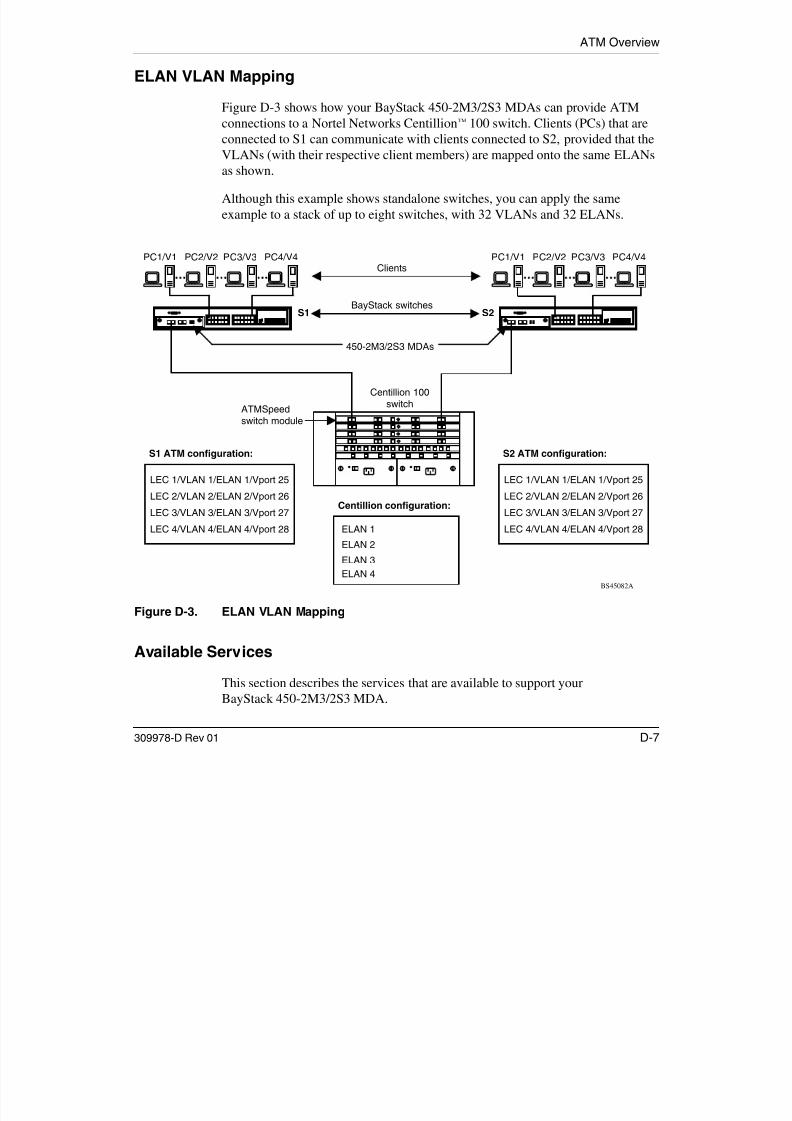
7/23/2019 Baystack 450
http://slidepdf.com/reader/full/baystack-450 345/399

7/23/2019 Baystack 450
http://slidepdf.com/reader/full/baystack-450 346/399
ATM Overview
Virtual Ports
Your BayStack 450-2M3/2S3 MDA has two physical OC-3 ports (A1 and A2) thatare used to connect to an ATM switch. As shown in Figure D-4, both physicalports are logically mapped to four LEC virtual ports (VPorts), LEC1 to LEC4.
Figure D-4. Virtual and Physical Ports
During initial powerup, your switch assigns the VPorts as a continuation of thedefault port numbering within the CI menus and screens. For example, if you have
a 12-port switch, VPorts LEC1 to LEC4 are assigned port 13 to port 16. For
450-2M3/2S3 MDA
LEC
Virtual ports
Physical portsA1
RxTx
A2
Front
L E C 1
L E C 2
L E C 3
L E C 4
BS45090A
RxTx

7/23/2019 Baystack 450
http://slidepdf.com/reader/full/baystack-450 347/399
309978-D Rev 01 D-9
a 12 port switch, VPorts LEC1 to LEC4 are assigned port 13 to port 16. For24-port models, the VPorts are assigned port 25 to port 28.
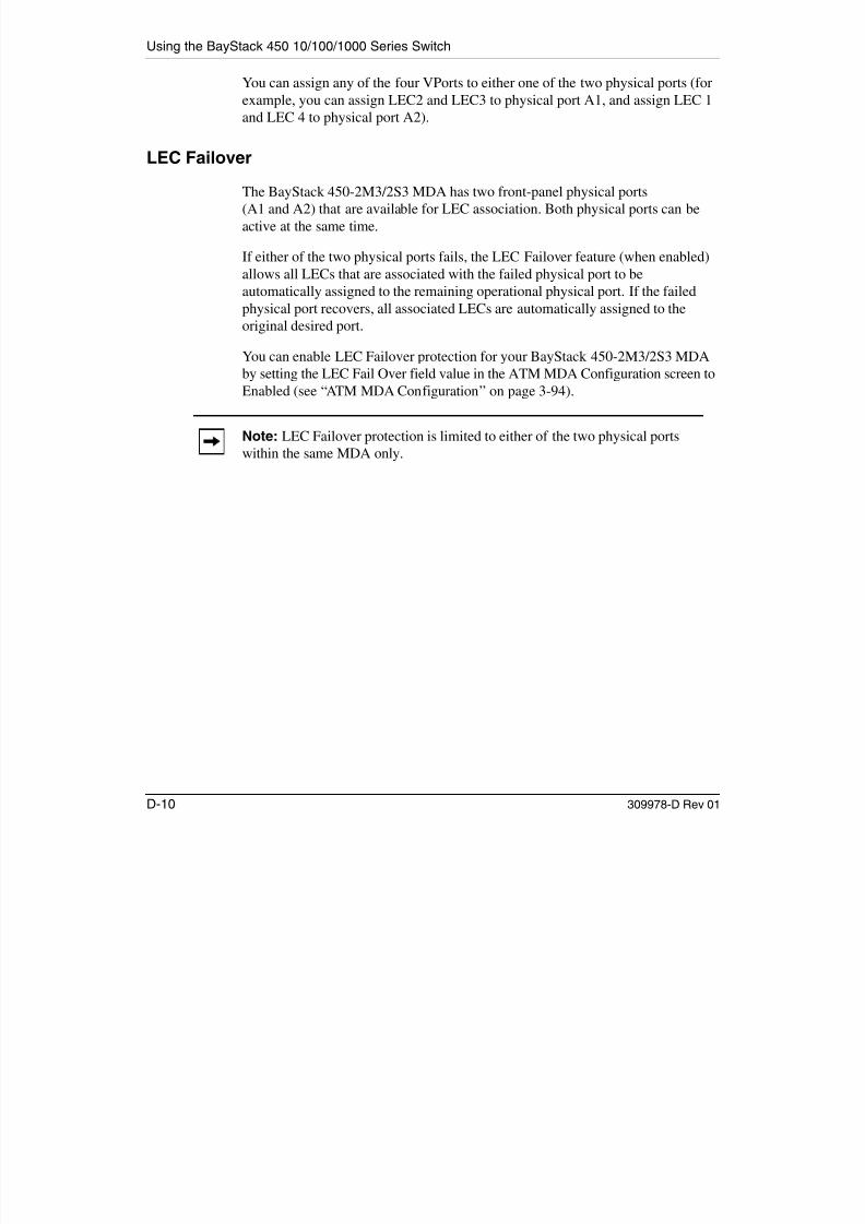
7/23/2019 Baystack 450
http://slidepdf.com/reader/full/baystack-450 348/399
ATM Overview
Spanning Tree on LEC VPorts
The default STP setting for your BayStack 450-2M3/2S3 MDA’s LEC VPorts isNormal Learning. Because BayStack 450 switches (software version V3.1, andearlier) do not support multiple STPs, you may have to disable STP on all LECVPorts. Figure D-5 shows possible consequences of not disabling the STP whenusing the BayStack 450-2M3/2S3 MDA.
Figure D-5. LEC VPorts with Spanning Tree Enabled (1 of 2)
As shown in Figure D-5, there are four virtual parallel links between the two
BayStack 450-2M3/2S3 MDAs. Each link consists of a LEC VPort on each sideon the same ELAN. Because STP is enabled for the four LEC VPorts, three of the
PC1 PC2
BS45091A
BayStack 450 BayStack 450
Legend
Blocking
Forwarding
450-2M3/2S3 MDA
LEC 2/ ELAN 2/ Vport 26
LEC 3/ ELAN 3/ Vport 27
LEC 1/ ELAN 1/ Vport 25
LEC 4/ ELAN 4/ Vport 28
450-2M3/2S3 MDA
ATM Network
LEC 2/ ELAN 2/ Vport 26
LEC 3/ ELAN 3/ Vport 27
LEC 1/ ELAN 1/ Vport 25
LEC 4/ ELAN 4/ Vport 28

7/23/2019 Baystack 450
http://slidepdf.com/reader/full/baystack-450 349/399
309978-D Rev 01 D-11
yon the same ELAN. Because STP is enabled for the four LEC VPorts, three of theLEC VPorts are in the Blocking state (based on the spanning tree algorithm).
Using the BayStack 450 10/100/1000 Series Switch
You can disable STP on the LEC VPorts with the risk of creating loops within thenetwork. If you are sure of a loop-free topology beyond the ATM uplink, then youcan disable the STP on the uplink ports to ensure connectivity on all four ELANs/ VLANs (Figure D-6).
Figure D-6. LEC VPorts with Spanning Tree Disabled (2 of 2)
Note: Because there is only one BayStack 450-2M3/2S3 MDA LEC VPort onone VLAN/ELAN, a loop-free network topology is ensured to some extent;however, it may not be sufficient to ensure a loop-free topology for the entirenetwork.
PC1 PC2
BS45092A
BayStack 450 BayStack 450
450-2M3/2S3 MDA
LEC 2/ ELAN 2/ Vport 26
LEC 3/ ELAN 3/ Vport 27
LEC 1/ ELAN 1/ Vport 25
LEC 4/ ELAN 4/ Vport 28
450-2M3/2S3 MDA
Legend
Blocking
Forwarding
ATM Network
LEC 2/ ELAN 2/ Vport 26
LEC 3/ ELAN 3/ Vport 27
LEC 1/ ELAN 1/ Vport 25
LEC 4/ ELAN 4/ Vport 28

7/23/2019 Baystack 450
http://slidepdf.com/reader/full/baystack-450 350/399
D-12 309978-D Rev 01
ATM Overview
Configuration Rules
This section summarizes important configuration rules for your BayStack 450-2M3/2S3 MDA.
Mixed Stack Configurations
Your BayStack 450-2M3/2S3 MDA does not support Business Policy Switches.
BayStack 450 Switches configured with BayStack 450-2M3/2S3 MDAs cannotoperate in mixed stack configurations that include Business Policy Switches.
Initial Configuration
During the initial configuration of the BayStack 450-2M3/2S3 MDA, you mustperform the following steps:
1. Configure the VLAN memberships for the four LECs in the VLANConfiguration screen.
2. Set the LEC State field to Enabled in the LEC Configuration screen.
See “Configuring the BayStack 450-2M3/2S3 MDAs” on page E-15 forflowcharts that detail the configuration steps for your BayStack 450-2M3/2S3MDA.
Enabling a LEC
Every LEC requires the following:
• A unique ELAN name
The ELAN name default value is: default
• An Actual Physical Port number (A1 or A2)
The physical port number default value is: A1
• A port-based VLAN.
You must assign the LEC to a new or existing port-based VLAN (using theVLAN Configuration screen) the first time a LEC is assigned, or wheneveryou issue the Reset to Default Settings command. In all other cases, a LEC’sVLAN membership is saved and restored following subsequent switch power

7/23/2019 Baystack 450
http://slidepdf.com/reader/full/baystack-450 351/399
309978-D Rev 01 D-13
cycles.
Using the BayStack 450 10/100/1000 Series Switch
LECs and VLAN Membership
The following configuration rules apply:
• You cannot assign a LEC as a tagged VLAN member.
• The PVID value for a LEC is read-only and must always equal its VLAN ID.
• LEC VLAN members do not support priority.
• A LEC can only be a member of one VLAN.
• A VLAN can only have one LEC member.
• LECs can be configured as members of port-based VLANs only; LECs cannotbe configured as members of protocol-based VLANs.
Console Differences
Many of the features that are available to your BayStack 450 switchEthernet-based ports cannot be supported by ATM. In those cases the VPorts thatrepresent the ATM LECs will either be hidden or displayed as read-only fields.
The following BayStack 450 switch features are not supported by the BayStack450-2M3/2S3 MDA:
• MultiLink Trunking
• Port Mirroring
• Filtering of untagged/tagged frames
• VLAN Traffic Class Priority
• Change of PVID
• Protocol-based VLANs
• VLAN tagging
• Rate Limiting

7/23/2019 Baystack 450
http://slidepdf.com/reader/full/baystack-450 352/399
D-14 309978-D Rev 01

7/23/2019 Baystack 450
http://slidepdf.com/reader/full/baystack-450 353/399

7/23/2019 Baystack 450
http://slidepdf.com/reader/full/baystack-450 354/399
Appendix E
Quick Steps to Features
If you are a system administrator with experience configuring BayStack 450switch VLANs, ATM MDAs, MultiLink Trunking, Port Mirroring, and IGMPSnooping, use the flowcharts on the following pages as quick configurationguides. The flowcharts refer you to the “configuration rules” appropriate for eachfeature.
The flowcharts cover the following topics:
• “Configuring 802.1Q VLANs” (page E-2)
• “Configuring Security Settings” (page E-5)
• “Configuring the BayStack 450-2M3/2S3 MDAs” (page E-15)
• “Configuring MultiLink Trunks” (page E-18)
• “Configuring Port Mirroring” (page E-19)
• “Configuring IGMP Snooping” (page E-21)
To learn more about: See:
802.1Q VLANs “Virtual Local Area Networks (VLANs)” on page 1-49.
Switch and Network Security “Security” on page 1-17.
BayStack 450-2M3/2S3 MDAs Appendix D, “ATM Overview.”
MultiLink Trunks “MultiLink Trunks” on page 1-78.
Port Mirroring “Port Mirroring (Conversation Steering)” on page 1-97.
IGMP Snooping “IGMP Snooping” on page 1-69.

7/23/2019 Baystack 450
http://slidepdf.com/reader/full/baystack-450 355/399
309978-D Rev 01 E-1

7/23/2019 Baystack 450
http://slidepdf.com/reader/full/baystack-450 356/399

7/23/2019 Baystack 450
http://slidepdf.com/reader/full/baystack-450 357/399

7/23/2019 Baystack 450
http://slidepdf.com/reader/full/baystack-450 358/399

7/23/2019 Baystack 450
http://slidepdf.com/reader/full/baystack-450 359/399
Using the BayStack 450 10/100/1000 Series Switch
Figure E-5. MAC Address-Based Security (1 of 2)
BS450104A
MAC Address SecurityConfiguration screen
1
Off-page reference
On-page reference
Key
Yes
NoPartition porton intrusion?
Yes
NoIsolate theintruding node?
2
Set MAC Address Securityfield to Enabled.
Yes
NoIssueSNMP trap on
intrusion?
1. Set the Partition Porton Intrusion field toEnabled.
2. Set the Partition Timefield to the appropriatevalue.
A
A
Set the DA Filtering onIntrusion field to Enabled.
2
B
SNMP Configurationscreen
Set the Generate SNMPTrap on Intrusion field
to Enabled.
Set the Trap Address andthe associated CommunityString field values (refer to
"SNMP Configuration inChapter 3).
Go to the SNMPConfiguration screen.
Return to the MAC AddressSecurity Configuration
screen.
Go to the MAC Address
Security Configuration screen.
Review "MAC Address-BasedSecurity" in Chapter 1.
B
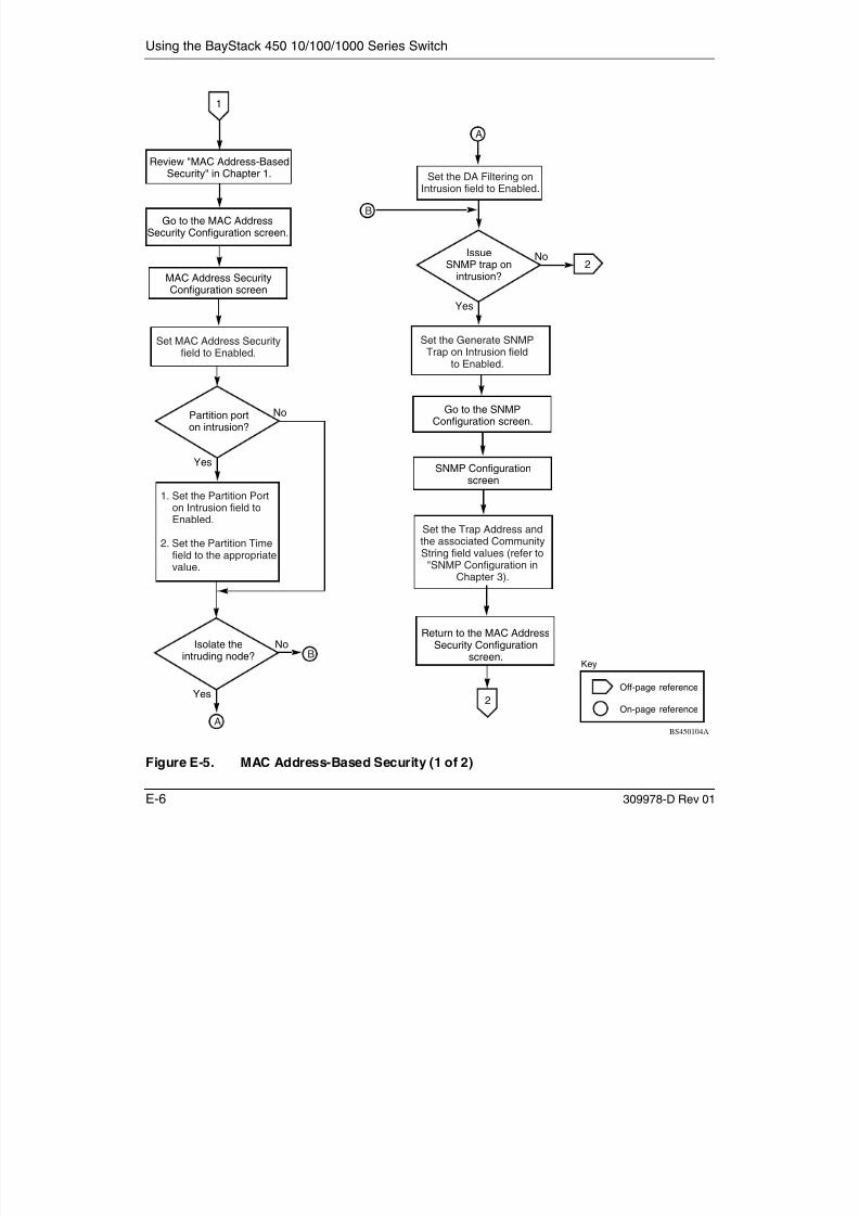
7/23/2019 Baystack 450
http://slidepdf.com/reader/full/baystack-450 360/399
E-6 309978-D Rev 01
Quick Steps to Features
Figure E-6. MAC Address-Based Security (2 of 2)
BS450105A
2
Off-page reference
On-page reference
Key
A
A
Yes
No
Add learned
MAC address toMAC Security
Table?
Go to the MAC AddressSecurity Table screen.
Set the appropriate values in
the MAC Address andAllowed Source fields,as required.
Go to the MAC AddressSecurity Port Configuration
screen.
Set the Security field valuesfor all required ports
to Enabled.
Done
MAC Address SecurityConfiguration screen
Set the Learn by Portsfield value, as required.
Set the Current LearningMode field value
to Enabled.
MAC Address SecurityTable screen
Wait until the requiredaddresses are learned.
Return to the MAC AddressSecurity Configuration
screen.
MAC Address SecurityTable screen
Set the Current LearningMode field value
to Disabled.
Go to the MAC AddressSecurity Port Lists screen.
Set the appropriate valuesin the Port Lists field.
Go to the MAC AddressSecurity Table screen.
MAC Address SecurityConfiguration screen
B
B
MAC Address Security PortLists screen
MAC Address Security PortConfiguration screen
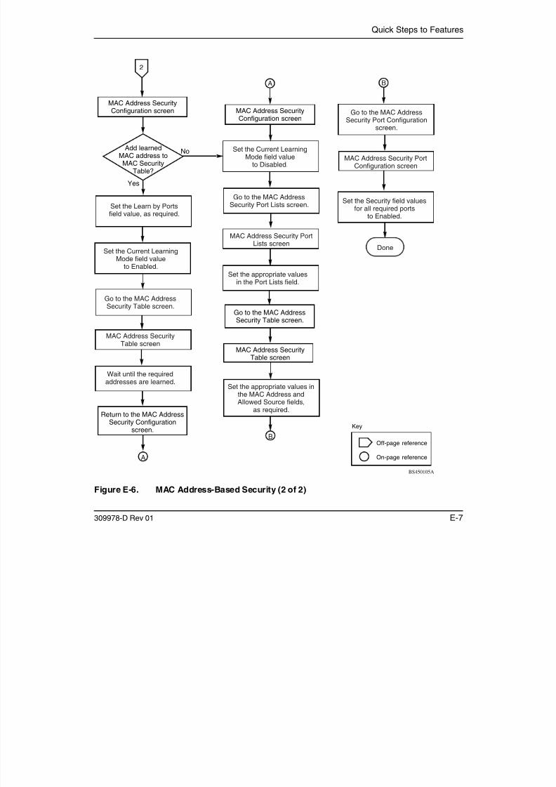
7/23/2019 Baystack 450
http://slidepdf.com/reader/full/baystack-450 361/399
309978-D Rev 01 E-7
Using the BayStack 450 10/100/1000 Series Switch
Figure E-7. EAPOL-Based Security
BS450106A
3
Off-page reference
On-page reference
Key
Go to the Console/Comm Port
Configuration screen. Set the EAPOL AdministrativeState field value to Enabled.
Set other field valuesas required.
Done
Configure the following
screen fields (as described in"Console/Comm PortConfiguration" in Chapter 3):
o Primary RADIUS Server
o Secondary RADIUS Server
o RADIUS UDP Port
o RADIUS Shared Secret
Go to the EAPOL SecurityConfiguration screen.
Set the Administrative Statusfield value to Auto, for each
secured port.
A
A
Console/Comm PortConfiguration screen
EAPOL SecurityConfiguration screen
Review "EAPOL-BasedSecurity" in Chapter 1.

7/23/2019 Baystack 450
http://slidepdf.com/reader/full/baystack-450 362/399
E-8 309978-D Rev 01
Quick Steps to Features
Figure E-8. RADIUS-Based Security (1 of 5)
BS450107A
Off-page reference
On-page reference
Key
Yes
No
A4
Go to the Console/Comm Port
Configuration screen.
Configure the followingscreen fields (as described in"Console/Comm PortConfiguration" in Chapter 3):
o Primary RADIUS Server
o Secondary RADIUS Server
o RADIUS UDP Port
o RADIUS Shared Secret
A
Console/Comm PortConfiguration screen
Review "RADIUS-BasedSecurity" in Chapter 1.
Yes
NoSet
console passwordprotection?
SetTELNET password
protection?
5
Yes
No
Yes
NoSet
local password?
SetRADIUS
authentication?
Yes
NoStandalone
switch?
Set the Console SwitchPassword Type field value
to Local Password.
Set the Console Read-OnlySwitch Password field
value, as required.
Set the Console Read-WriteSwitch Password field
value, as required.
C
7
8
Yes
NoSetTELNET password
protection?
5
C
Done
B
B
B
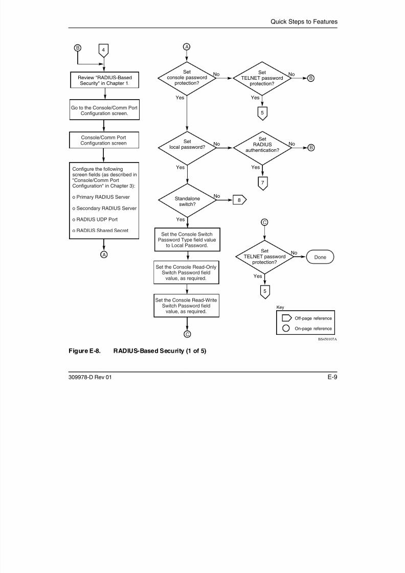
7/23/2019 Baystack 450
http://slidepdf.com/reader/full/baystack-450 363/399
309978-D Rev 01 E-9
Using the BayStack 450 10/100/1000 Series Switch
Figure E-9. RADIUS-Based Security (2 of 5)
BS450108A
Off-page reference
On-page reference
Key
4
Yes
No
Yes
NoSet
local password?
SetRADIUS
authentication?
Yes
NoStandalone
switch?
Set the TELNET SwitchPassword Type field value
to Local Password.
Set the Console Read-OnlySwitch Password field
value, as required.
Set the Console Read-WriteSwitch Password field
value, as required.
Yes
NoStandalone
switch?
Set the TELNET SwitchPassword Type field valueto RADIUS Authentication.
5
Set the TELNET StackPassword Type field valueto RADIUS Authentication.
6
Done
Done
Done

7/23/2019 Baystack 450
http://slidepdf.com/reader/full/baystack-450 364/399
E-10 309978-D Rev 01
Quick Steps to Features
Figure E-10. RADIUS-Based Security (3 of 5)
BS450109A
Off-page reference
On-page reference
Key
Done
6
Set the TELNET StackPassword Type field value
to Local Password.
Set the Console Read-OnlySwitch Password field
value, as required.
Set the Console Read-WriteSwitch Password field
value, as required.

7/23/2019 Baystack 450
http://slidepdf.com/reader/full/baystack-450 365/399
309978-D Rev 01 E-11
Using the BayStack 450 10/100/1000 Series Switch
Figure E-11. RADIUS-Based Security (4 of 5)
Yes
NoStandalone
switch?
Set the Console SwitchPassword Type field valueto RADIUS Authentication.
7
Set the Console StackPassword Type field valueto RADIUS Authentication.
BS450110A
Off-page reference
On-page reference
Key
Yes
NoSetTELNET password
protection?
5
Done

7/23/2019 Baystack 450
http://slidepdf.com/reader/full/baystack-450 366/399
E-12 309978-D Rev 01
Quick Steps to Features
Figure E-12. RADIUS-Based Security (5 of 5)
BS450111A
Off-page reference
On-page reference
Key
8
Set the Console StackPassword Type field value
to Local Password.
Set the Console Read-OnlySwitch Password field
value, as required.
Set the Console Read-WriteSwitch Password field
value, as required.
Yes
NoSetTELNET password
protection?
5
Done

7/23/2019 Baystack 450
http://slidepdf.com/reader/full/baystack-450 367/399
309978-D Rev 01 E-13
Using the BayStack 450 10/100/1000 Series Switch
Figure E-13. SNMP-Based Security
BS450112A
Off-page reference
On-page reference
Key
9
Go to the TELNET/SNMPManager List Configuration
screen.
Configure the followingscreen fields (as described in"TELNET/SNMP ManagerList Configuration"in Chapter 3):
o Allowed Source IP Address
o Allowed Source Mask
TELNET/SNMPManager List Configuration
screen
Review "SNMP-BasedSecurity" in Chapter 1.
Done
Note:SNMP security configuration
values also apply toTELNET logins.

7/23/2019 Baystack 450
http://slidepdf.com/reader/full/baystack-450 368/399
E-14 309978-D Rev 01
Quick Steps to Features
Configuring the BayStack 450-2M3/2S3 MDAs
To configure or modify the BayStack 450-2M3/2S3 MDA, follow the flowchartsin Figures E-14 to E-16.
Choose ATM MDA Configuration (or press a) from the ATM Configuration Menuto open the ATM MDA Configuration screen.
Figure E-14. Configuring the BayStack 450-2M3/2S3 MDA (1 of 3)
Yes
No
BS45093A
Assigning LECto an existing
VLAN?
Off-page reference
On-page reference
Key
You cannot enablean LEC without assigning
it to a VLAN.
A
Go to the VLAN ConfigurationMenu to assign the LEC:
3. Press v to open theVLAN Configuration Menu.
2. Press r to return to theSwitch Configuration Menu.
4. Press v to open the VLANConfiguration screen.
2
1
1. Press [Ctrl]-R to return to theATM Configuration Menu.
VLAN Configuration screen
Select the appropriateATM MDA to configure.
Press [Ctrl]-R to return to theATM Configuration Menu.
Select the appropriate LEC to
configure, then press [Return].
Choose LEC Configuration
(or press l) to open theLEC Configuration screen.
Configure the appropriate ATM MDA
fields as described in this guide(see Chapter 3, "ATM MDA Configuration").
Determine the VPort numberthat is associated with
the chosen LEC.
A
ATM MDA Configuration screen
LEC Configuration screen4

7/23/2019 Baystack 450
http://slidepdf.com/reader/full/baystack-450 369/399
309978-D Rev 01 E-15
Using the BayStack 450 10/100/1000 Series Switch
E 16 309978 D R 01
Figure E-15. Configuring the BayStack 450-2M3/2S3 MDA (2 of 3)
Yes
No
BS45094A
Is filteringcorrect?
Off-page reference
On-page reference
Key
Assign the VPort to aPort-Based VLAN.
2
Create a Port-Based VLAN.
1
Press [Ctrl]-R to returnto previous menu.
Choose VLAN PortConfiguration
(or press c).
Set the Port field asappropriate for your
VPort configuration.
Set unregistered, tagged,untagged filters
if necessary.
3
3
VLAN Port Configuration screen

7/23/2019 Baystack 450
http://slidepdf.com/reader/full/baystack-450 370/399
E-16 309978-D Rev 01
Quick Steps to Features
309978 D Rev 01 E 17
Figure E-16. Configuring the BayStack 450-2M3/2S3 MDA (3 of 3)
For detailed information about the BayStack 450-2M3/2S3 MDA configurationscreens, see “ATM Configuration Menu” on page 3-89.
For conceptual information about the BayStack 450-2M3/2S3 MDA andconfiguration tips, see Appendix D, “ATM Overview.”
BS450113A
Off-page reference
On-page reference
Key
Yes
NoConfiguringanotherLEC?
3
4
Return to theLEC Configuration screen.
Select the appropriate LEC toconfigure, then press [Return].
LEC Configuration screen
Configure the appropriate LEC fields(see Chapter 3, "LEC Configuration").
Done

7/23/2019 Baystack 450
http://slidepdf.com/reader/full/baystack-450 371/399
309978-D Rev 01 E-17
Using the BayStack 450 10/100/1000 Series Switch
E-18 309978-D Rev 01
Configuring MultiLink Trunks
To create or modify a MultiLink trunk, follow the flowchart in Figure E-17.
Choose MultiLink Trunk Configuration (or press t) from the MultiLink TrunkConfiguration Menu to open the MultiLink Trunk Configuration screen.
Figure E-17. Configuring MultiLink Trunks
Yes
No
No
Configure STP field.
Enable Trunk Status field(see "MultiLink TrunkingConfiguration Rules").
Configure trunk members(see "MultiLink TrunkingConfiguration Rules").
BS450114A
Are alltrunk members
configured?
Is trunkSTP Enabled?
Yes
Is trunkEnabled?
Yes
No
Done
MultiLink TrunkConfiguration screen

7/23/2019 Baystack 450
http://slidepdf.com/reader/full/baystack-450 372/399
E 18 309978 D Rev 01
Quick Steps to Features
309978-D Rev 01 E-19
Configuring Port Mirroring
To create or modify port-mirroring ports, follow the flowcharts in Figures E-18 and E-19.
Choose Port Mirroring Configuration (or press i) from the Switch ConfigurationMenu screen to open the Port Mirroring Configuration screen.
Figure E-18. Configuring Port Mirroring (1 of 2)
Yes
No
NoSet Monitoring Mode field.
Port MirroringConfiguration screen
Set Monitor Port field (see"Port Mirroring Configuration Rules").
Configure Ports X and Y fields (see
"Port Mirroring Configuration Rules").
BS45051A
IsMonitoring Mode
field set?
IsMonitor Port
field set?
Yes
IsMonitor Port
set for port-basedmode?
Yes
Yes
No1
Are
Ports X and Y fieldsconfigured?
No
1
2
Off-page reference
On-page reference
Key

7/23/2019 Baystack 450
http://slidepdf.com/reader/full/baystack-450 373/399
309978 D Rev 01 E 19
Using the BayStack 450 10/100/1000 Series Switch
E-20 309978-D Rev 01
Figure E-19. Configuring Port Mirroring (2 of 2)
Yes
No
No
Enable Port Mirroring(see "Port Mirroring Configuration
Rules").
BS45052A
AreAddress A and B
configured?
IsPort Mirroring
Enabled?
Yes
1
Done
2
Configure Addresses.
Off-page reference
On-page reference
Key
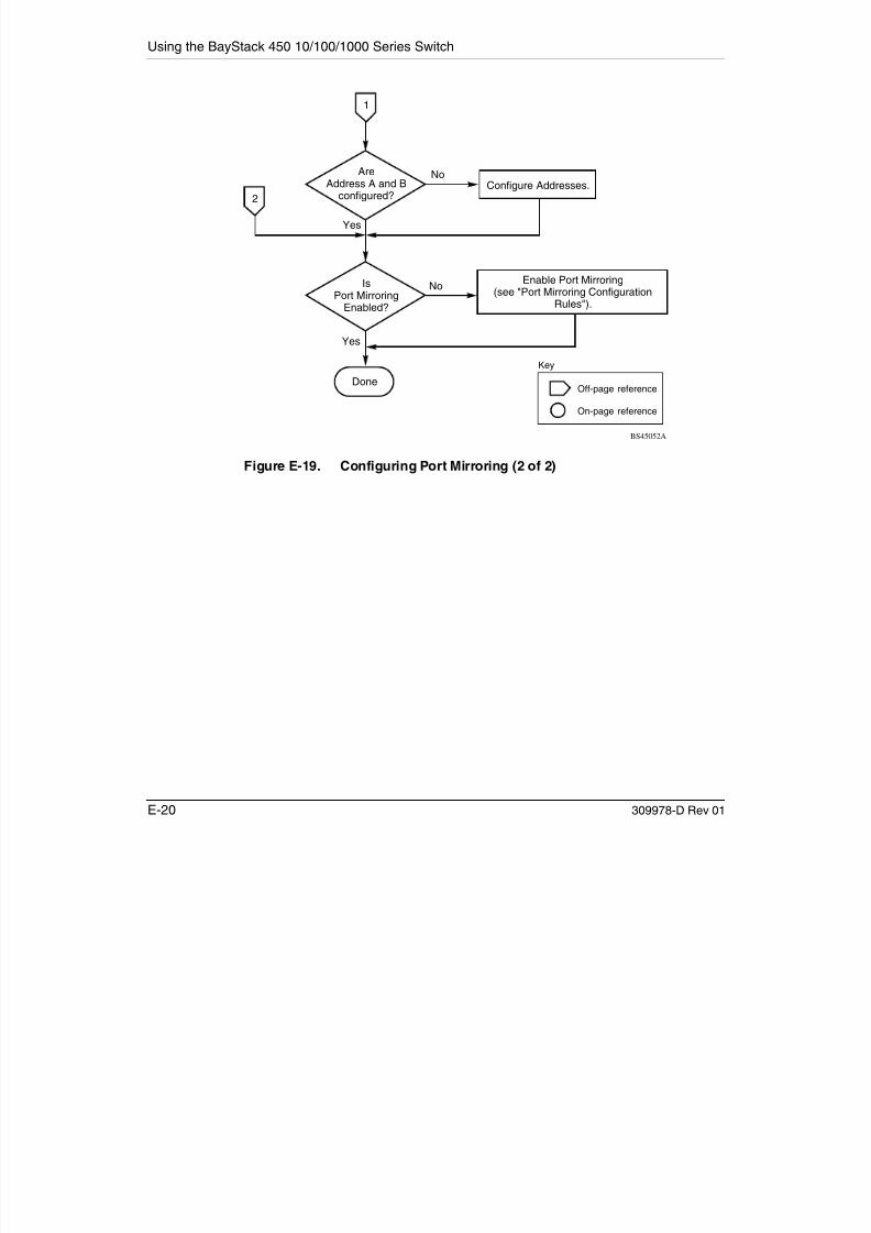
7/23/2019 Baystack 450
http://slidepdf.com/reader/full/baystack-450 374/399
Quick Steps to Features
309978-D Rev 01 E-21
Configuring IGMP Snooping
To create or modify IGMP Snooping ports, follow the flowcharts in Figures E-20 to E-22.
Choose IGMP Configuration (or press g) from the Switch Configuration Menuscreen to open the IGMP Configuration screen.
Figure E-20. Configuring IGMP Snooping (1 of 3)
Yes
No
BS450115A
Are VLANscreated/port members
configured?
IsSnooping field
Enabled?
Yes
Yes
No
Isthe Proxy field set
correctly?
No
2
IGMP Configuration screen
Go to VLAN flowchart. Create VLANs/ configure port members, as required.
Set the correct valuefor the Proxy field.
Off-page reference
On-page reference
Key
IGMP Snooping feature is disabled.To activate the feature, set the
Snooping field to Enabled.

7/23/2019 Baystack 450
http://slidepdf.com/reader/full/baystack-450 375/399
Using the BayStack 450 10/100/1000 Series Switch
E-22 309978-D Rev 01
Figure E-21. Configuring IGMP Snooping (2 of 3)
Yes
No
No
BS450116A
Is theRobust Value field
set correctly?
Is the QueryTime field set
correctly?
Yes
Is the SetRouter Ports fieldset correctly?
Yes
No
3
2
Set the correct value forthe Query Time field.
Set the correct value forthe Robust Value field.
Set the correct value forthe IGMP version in theSet Router Ports field.
Off-page reference
On-page reference
Key

7/23/2019 Baystack 450
http://slidepdf.com/reader/full/baystack-450 376/399
Quick Steps to Features
309978-D Rev 01 E-23
Figure E-22. Configuring IGMP Snooping (3 of 3)
Yes
No
No
All trunk members for that trunkare automatically configured as
Static Router Ports.
Off-page reference
On-page reference
BS450117A
Key
Are allStatic Router Ports
set correctly?
Are anyStatic Router Ports
trunk members?
Yes
3
Done
Set Static Router Ports as required(see "IGMP Configuration Rules").
All VLANs are now set correctly foreach Static Router Port.

7/23/2019 Baystack 450
http://slidepdf.com/reader/full/baystack-450 377/399

7/23/2019 Baystack 450
http://slidepdf.com/reader/full/baystack-450 378/399
309978-D Rev 01 F-1
Appendix F
Connectors and Pin Assignments
This appendix describes the BayStack 450 switch port connectors and pinassignments.
This appendix covers the following topics:
• “RJ-45 (10BASE-T/100BASE-TX) Port Connectors” (page F-1)
• “MDI and MDI-X Devices” (page F-2)• “DB-9 (RS-232-D) Console/Comm Port Connector” (page F-5)
RJ-45 (10BASE-T/100BASE-TX) Port Connectors
The RJ-45 port connectors (Figure F-1) are wired as MDI-X ports to connect end
stations without using crossover cables. (See “MDI and MDI-X Devices” onpage F-2 for information about MDI-X ports.) For 10BASE-T connections, useCategory 3 (or higher) UTP cable. For 100BASE-TX connections, use onlyCategory 5 UTP cable.
Figure F-1. RJ-45 (8-Pin Modular) Port Connector
1 8
616EA

7/23/2019 Baystack 450
http://slidepdf.com/reader/full/baystack-450 379/399
Using the BayStack 450 10/100/1000 Series Switch
F-2 309978-D Rev 01
Table F-1 lists the RJ-45 (8-pin modular) port connector pin assignments.
MDI and MDI-X DevicesMedia dependent interface (MDI) is the IEEE standard for the interface tounshielded twisted pair (UTP) cable.
For two devices to communicate, the transmitter of one device must connect to thereceiver of the other device. The connection is established through a crossoverfunction, which can be a crossover cable or a port that implements the crossover
function internally.
Ports that implement the crossover function internally are known as MDI-X ports,where X refers to the crossover function.
The following sections describe the use of straight-through and crossover cablesfor connecting MDI and MDI-X devices.
Table F-1. RJ-45 Port Connector Pin Assignments
Pin Signal Description
1 RX+ Receive Data +
2 RX- Receive Data -
3 TX+ Transmit Data +
4 Not applicable Not applicable
5 Not applicable Not applicable
6 TX- Transmit Data -
7 Not applicable Not applicable
8 Not applicable Not applicable
Note: For the transmitter of one device to connect to the receiver of anotherdevice, the total number of crossovers must always be an odd number.

7/23/2019 Baystack 450
http://slidepdf.com/reader/full/baystack-450 380/399

7/23/2019 Baystack 450
http://slidepdf.com/reader/full/baystack-450 381/399
Using the BayStack 450 10/100/1000 Series Switch
F-4 309978-D Rev 01
MDI-X to MDI-X Cable Connections
If you are connecting the BayStack 450 switch to a device that also implementsMDI-X ports, use a crossover cable (Figure F-3).
Figure F-3. MDI-X to MDI-X Cable Connections
1 81 8 8 1 8 1
RX+
RX-
TX+
TX-
RX+
RX-
TX+
TX-
MDI-X port
BayStack 450 switch Switch or hub
Crossover cable MDI-X port
T
R
T
R
1
2
3
4
5
6
7
8
1
2
3
4
5
6
7
8
1
2
3
4
5
6
7
8
1
2
3
4
5
6
7
8
BS45057A
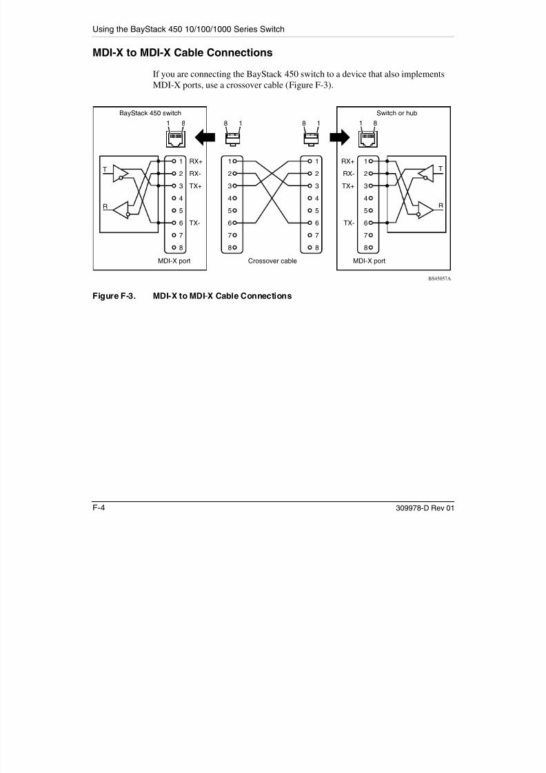
7/23/2019 Baystack 450
http://slidepdf.com/reader/full/baystack-450 382/399
Connectors and Pin Assignments
309978-D Rev 01 F-5
DB-9 (RS-232-D) Console/Comm Port Connector
The DB-9 Console/Comm Port connector (Figure F-4) is configured as a datacommunications equipment (DCE) connector. The DSR and CTS signal outputsare always asserted; the CD, DTR, RTS, and RI signal inputs are not used. Thisconfiguration enables a management station (a PC or console terminal) to connectdirectly to the switch using a straight-through cable.
Figure F-4. DB-9 Console/Comm Port Connector
Table F-2 lists the DB-9 Console/Comm Port connector pin assignments.
Table F-2. DB-9 Console/Comm Port Connector Pin Assignments
Pin Signal Description
1 CD Carrier detect (not used)
2 TXD Transmit data (output)
3 RXD Receive data (input)
4 DTR Data terminal ready (not used)
5 GND Signal ground
6 DSR Data set ready (output always asserted)
7 RTS Request to send (not used)
8 CTS Clear to send (output always asserted)
9 RI Ring indicator (not used)
Shell Chassis ground
5
6 9
1
619EA

7/23/2019 Baystack 450
http://slidepdf.com/reader/full/baystack-450 383/399

7/23/2019 Baystack 450
http://slidepdf.com/reader/full/baystack-450 384/399

7/23/2019 Baystack 450
http://slidepdf.com/reader/full/baystack-450 385/399
Using the BayStack 450 10/100/1000 Series Switch
G-2 309978-D Rev 01
System Characteristics (page 3-16) Reset Count 1
Last Reset Type Power Cycle
Power Status Primary Power
sysContact Zero-length string
sysName Zero-length string
sysLocation Zero-length stringMAC Address Table (page 3-22) Aging Time 300 seconds
Find an Address 00-00-00-00-00-00
(no MAC address assigned)
Port Mirroring Address A: 00-00-00-00-00-00
(no MAC address assigned)
Port Mirroring Address B: 00-00-00-00-00-00
(no MAC address assigned)MAC Address Security Configuration(page 3-26)
MAC Address Security
Disabled
MAC Address Security
SNMP_Locked
Disabled
Partition Port on Intrusion Disabled
Partition Time 1 second
DA Filtering on Intrusion Disabled
Generate SNMP Trap on
Intrusion
Disabled
Clear by Ports NONE
Learn by Ports NONE
Current Learning Mode Disabled
MAC Address Security Port Configuration (page 3-30)
Security
Disabled
MAC Address Security Port Lists
(page 3-33)
Port List
Blank field
(continued)
Table G-1. Factory Default Settings for the BayStack 450 Switch (continued)
CI screen Field Default setting

7/23/2019 Baystack 450
http://slidepdf.com/reader/full/baystack-450 386/399
Default Settings
309978-D Rev 01 G-3
MAC Address Security Table (page 3-37) Find an Address 00-00-00-00-00-00
(no MAC address assigned)
MAC Address - - - - - (no MAC address
assigned)
Allowed Source - (Blank field)
EAPOL Security Configuration
(page 3-40)
Unit 1
Port 1
Initialize No
Administrative Status Force Authorized
Operational Status Authorized
Administrative Traffic Control Incoming and Outgoing
(read-only)
Operational Traffic Control Incoming and Outgoing
(read-only)
Re-authenticate Now No
Re-authentication Enabled
Re-authentication Period 3600 seconds
Quiet Period 60 seconds
Transmit Period 30 seconds
Supplicant Timeout 30 seconds
Server Timeout 30 seconds
Maximum Requests 2 attempts
VLAN Configuration (page 3-46) Create VLAN 1
Delete VLAN blank field
VLAN Name VLAN # (VLAN number )
Management VLAN Yes
VLAN Type Port-Based
Protocol Id (PID) None
User-defined PID 0x0000
(continued)
Table G-1. Factory Default Settings for the BayStack 450 Switch (continued)
CI screen Field Default setting
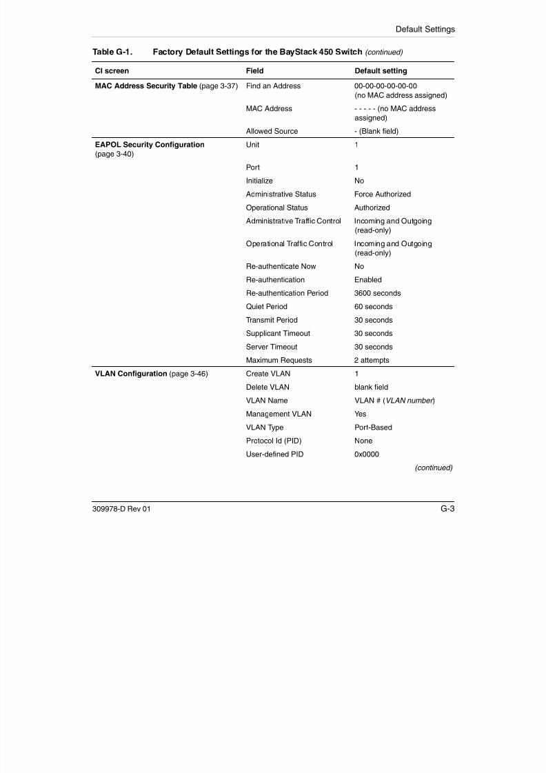
7/23/2019 Baystack 450
http://slidepdf.com/reader/full/baystack-450 387/399
Using the BayStack 450 10/100/1000 Series Switch
G-4 309978-D Rev 01
VLAN State Inactive
Port Membership U (all ports assigned as
untagged members of VLAN 1)
VLAN Port Configuration (page 3-52) Unit 1
Port 1
Filter Tagged Frames No
Filter Untagged Frames No
Filter Unregistered Frames No
Port Name Unit 1, Port 1
PVID 1
Port Priority 0
Tagging Untagged Access
AutoPVID (all ports) Disabled
VLAN Display by Port (page 3-56) Unit 1
Port 1
PVID 1 (read-only)
Port Name Unit 1, Port 1 (read-only)
Traffic Class Configuration (page 3-57) Traffic Class Low
Port Configuration (page 3-59) Unit 1
Status Enabled (for all ports)
LnkTrap On
Autonegotiation Enabled (for all ports)
Speed/Duplex 100Mbs/Half (when
Autonegotiation is Disabled)
High Speed Flow Control Configuration (page 3-62)
Unit 1 to 8 (depending on
configuration status)
Autonegotiation Enabled
Flow Control Disabled
(continued)
Table G-1. Factory Default Settings for the BayStack 450 Switch (continued)
CI screen Field Default setting

7/23/2019 Baystack 450
http://slidepdf.com/reader/full/baystack-450 388/399
Default Settings
309978-D Rev 01 G-5
Note: The following two fields only appear when a single Phy
MDA with a separate redundant Phy port is installed.
Preferred Phy Right
Active Phy Read-only field indicating the
operational Phy port (Right,
Left, or None)
MultiLink Trunk Configuration(page 3-64) Trunk Members (Unit/Port) Zero-length string
STP Learning Normal
Trunk Mode Basic
Trunk Status Enabled
Trunk Name Trunk #1 to Trunk #6
MultiLink Trunk Utilization (page 3-68) Traffic Type Rx and Tx
Port Mirroring Configuration (page 3-71) Monitoring Mode Disabled
Monitor/Unit Port Zero-length string
Unit/Port X Zero-length string
Unit/Port Y Zero-length string
Address A 00-00-00-00-00-00
(no MAC address assigned)
Address B 00-00-00-00-00-00
(no MAC address assigned)
Rate Limiting Configuration (page 3-75) Packet Type Both
Limit None
IGMP Configuration (page 3-79) VLAN 1
Snooping Enabled
Proxy Enabled
Robust Value 2
Query Time 125 seconds
Set Router Ports Version 1
Static Router Ports - (for all ports)
Multicast Group Membership (page 3-83) VLAN 1
(continued)
Table G-1. Factory Default Settings for the BayStack 450 Switch (continued)
CI screen Field Default setting

7/23/2019 Baystack 450
http://slidepdf.com/reader/full/baystack-450 389/399
Using the BayStack 450 10/100/1000 Series Switch
G-6 309978-D Rev 01
Port Statistics (page 3-85) Unit 1
Port 1
LEC Configuration (page 3-91) LEC 1
LEC Status Disable
LEC State Disabled
ELAN Name default
VLAN 0 (no VLAN assigned)
LEC Vport 13 (12-port models) 25 (24-port models)
Desired Physical Port A1
Actual Physical Port A1
ATM MDA Configuration (page 3-94) LEC Fail Over Disabled
LECS Address Method ATM Forum
User Defined Address 39-00-00-00-00-00-00-00 -00-00-00-00-00-00-00-00 -00-00-00-00
UNI Version 3.1
PHY Type SONET
ATM MDA Software Download(page 3-97)
Image Filename Zero-length string
TFTP Server IP Address 0.0.0.0 (no IP address assigned)
Start TFTP Transfer of MDA
Image
No
Console/Comm Port Configuration (page 3-100)
Console Port Speed 9600 Baud
Console Switch Password Type None
Console Stack Password Type None
TELNET Switch Password
Type
None
TELNET Stack Password Type None
(continued)
Table G-1. Factory Default Settings for the BayStack 450 Switch (continued)
CI screen Field Default setting

7/23/2019 Baystack 450
http://slidepdf.com/reader/full/baystack-450 390/399
Default Settings
309978-D Rev 01 G-7
Console Read-Only Switch
Password
user
Console Read-Write Switch
Password
secure
Console Read-Only Stack
Password
user
Console Read-Write StackPassword secure
Primary RADIUS Server 0.0.0.0
Secondary RADIUS Server 0.0.0.0
RADIUS UDP Port 1645
RADIUS Shared Secret Blank field
Renumber Stack Units (page 3-107) New Unit Number Current stack order
(Only appears when the switch is a
participant in a stack configuration.)
Renumber units with new
setting?
No
Spanning Tree Port Configuration (page 3-112)
Unit
1
Participation Normal Learning
Priority 128
Path Cost 10 or 100
Spanning Tree Switch Settings(page 3-115)
Bridge Priority 8000 (read-only)
Designated Root 8000 (bridge_id) (read-only)
Root Port Unit: 0 / Port: 0 (read-only)
Root Path Cost 0 (read-only)
Hello Time 2 seconds (read-only)Maximum Age Time 20 seconds (read-only)
Forward Delay 15 seconds (read-only)
Bridge Hello Time 2 seconds (read-only)
Bridge Maximum Age Time 20 seconds (read-only)
Bridge Forward Delay 15 seconds (read-only)
(continued)
Table G-1. Factory Default Settings for the BayStack 450 Switch (continued)
CI screen Field Default setting

7/23/2019 Baystack 450
http://slidepdf.com/reader/full/baystack-450 391/399
Using the BayStack 450 10/100/1000 Series Switch
G-8 309978-D Rev 01
TELNET/SNMP Manager List
Configuration (page 3-118)
TELNET Access Enabled
Login Timeout 1 minute
Login Retries 3
Inactivity Timeout 15 minutes
Event Logging All
Allowed Source IP Address (10 user-configurable fields)
First field: 0.0.0.0 (no IP address assigned)
Remaining nine fields:
255.255.255.255 (any address is allowed)
Allowed Source Mask (10 user-configurable fields)
First field: 0.0.0.0
(no IP address assigned)
(For details about this field, seeTable 3-41 on page 3-119.)
Remaining nine fields:255.255.255.255 (any address is allowed)
Software Download (page 3-121) Image Filename Zero-length string
TFTP Server IP Address 0.0.0.0 (no IP address assigned)
Start TFTP Load of New Image No
Configuration File (page 3-125) Configuration Image Filename Zero-length string
TFTP Server IP Address 0.0.0.0 (no IP address assigned)
Copy Configuration Image to
Server
No
Retrieve Configuration Image
from Server
No
Table G-1. Factory Default Settings for the BayStack 450 Switch (continued)
CI screen Field Default setting

7/23/2019 Baystack 450
http://slidepdf.com/reader/full/baystack-450 392/399
309978-D Rev 01 H-1
Appendix H
Sample BootP Configuration File
This appendix provides a sample BootP configuration file. The BootP serversearches for this file, called bootptab (or BOOTPTAB.TXT , depending on youroperating system), which contains the site-specific information (including IPaddresses) needed to perform the software download and configuration. You canmodify this sample BootP configuration file or create one of your own.
A sample BootP configuration file follows:
# The following is a sample of a BootP configuration file that was extracted# from a Bay Networks EZ LAN network management application. Note that other# BootP daemons can use a configuration file with a different format.## Before using your switch BootP facility, you must customize your BootP# configuration file with the appropriate data.
## Blank lines and lines beginning with '#' are ignored.## Legend:## first field -- hostname# ht -- hardware type# ha -- host hardware address# tc -- template host (points to similar host entry)# ip -- host IP address# hd -- bootfile home directory# bf -- bootfile# EZ dt -- device type# EZ fv -- firmware version# EZ av -- agent version## Fields are separated with a pipe (|) symbol. Forward slashes (/) are
# required to indicate that an entry is continued to the next line.#

7/23/2019 Baystack 450
http://slidepdf.com/reader/full/baystack-450 393/399
Using the BayStack 450 10/100/1000 Series Switch
H-2 309978-D Rev 01
Note: When setup via BOOTP, the BayStack 450 only utilizes the IP, subnetmask, and gateway fields. Any other fields that are defined in the BOOTP file
are ignored.
# Caution## Omitting a Forward slash (/) when the entry is continued to the next# line, can cause the interruption of the booting process or the# incorrect image file to download. Always include forward slashes# where needed.## Important Note:#
# If a leading zero (0) is used in the IP address it is calculated as an# octal number. If the leading character is "x" (upper or lower case),# it is calculated as a hexadecimal number. For example, if an IP address# with a base 10 number of 45 is written as .045 in the BOOTPTAB.TXT file,# the Bootp protocol assigns .037 to the client.## Global entries are defined that specify the parameters used by every device.# Note that hardware type (ht) is specified first in the global entry.
## The following global entry is defined for an Ethernet device. Note that this# is where a client's subnet mask (sm) and default gateway (gw) are defined.#global1|/
|ht=ethernet|/|hd=c:\opt\images|/|sm=255.255.255.0|/|gw=192.0.1.0|
## The following sample entry describes a BootP client:
bay1|ht=ethernet|ha=0060fd000000|ip=192.0.0.1|hd=c:\ezlan\images|bf=b450_100.img
# Where:# host name: bay1# hardware type: Ethernet# MAC address: 00-60-FD-00-00-00
# IP address: 192.0.0.1# home directory of boot file: c:\ezlan\images# boot file: b450_100.img
|ht=ethernet|/
|sm=255.255.255.2|/
|gw=192.0.1.0|
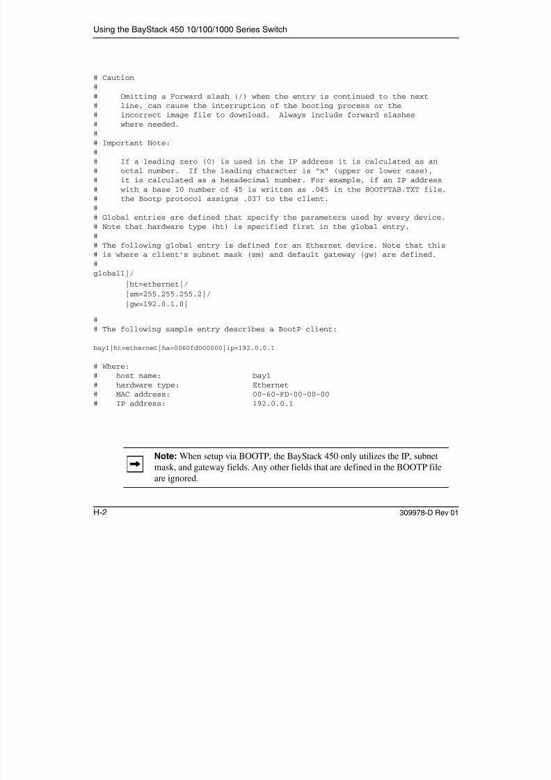
7/23/2019 Baystack 450
http://slidepdf.com/reader/full/baystack-450 394/399
309978-D Rev 01 Index-1
A
acronyms, 1-xxviii
Actual Hello Interval, 3-116Aging Time field, 3-23
Allowed Source IP Address field, 3-120
Allowed Source Mask field, 3-120
asynchronous transfer mode450-2M3/2S3 MDA, C-12CI menus and screens, 3-89configuration flowcharts, E-1network example, 2-36setting up, 2-36terminology, concepts and examples, D-1
ATM. See asynchronous transfer mode
Authentication Trap field, 3-15
Autonegotiationdescription, 2-31
field, 3-61modes, 4-8troubleshooting, 4-8
AutoPVID, 2-66, 3-55
Autosensing, 2-31
B
Base unit, 2-43BayStack 450 switch
connectors, F-1default port settings for VLANs, 2-53features, 2-13 to 2-15front panel, 2-2
BootP Request Mode field, 3-10
BootP. See Bootstrap Protocol
Bootstrap Protocol (BootP)Always setting, 3-13
automatic IP configuration, 2-31BOOTPTAB.TXT file, H-1
choosing a request mode, 3-11Disabled setting, 3-12Last Address setting, 3-12sample configuration file, H-1When Needed setting, 3-13
Bridge Forward Delay field, 3-117
Bridge Hello Time field, 3-117
Bridge Maximum Age Time field, 3-117
Bridge Priority field, 3-116
Broadcasts field, 3-86
C
Cascade module, 2-41
Clear All Port Statistics option, 3-21
Collisions field, 3-88Comm Port Data Bits field, 3-100
Comm Port Parity field, 3-100
Comm Port Stop Bits field, 3-101
Community String field, 3-15
Configurable field, 3-10
configuration rules
IGMP Snooping, 2-73MultiLink Trunking, 2-90Port Mirroring, 2-103VLANs, 2-68
connectors, F-1AC power receptacle, 2-10DB-9 console/comm port connector, F-5RJ-45 port connector, F-1
Console Interface (CI)cable, 2-10
Index

7/23/2019 Baystack 450
http://slidepdf.com/reader/full/baystack-450 395/399
Index-2 309978-D Rev 01
connection, 2-10main menu, 3-5menus, using, 3-2
Console Password field, 3-102Console Port Speed field, 3-101
Console Read-Only Password field, 3-103, 3-104
Console Read-Write Password field, 3-103, 3-105
console/comm portconfiguration options, 3-6configuration screen, 3-100
connecting to terminal, 2-11illustration, F-5pin assignments, F-5
conventions, text, 1-xxvii
conversation steering, 2-97
cooling fans, 2-13
crossover cable, F-4
customer support, 1-xxxi
D
data communication equipment (DCE), 2-10
DB-9 connector, 2-10
DB-9 console/comm port connector, F-5
Declaration of Conformity, A-4
Default Gateway field, 3-11default settings, G-1
Deferred Packets field, 3-88
Designated Root field, 3-116
Display Event Log option, 3-7
Display Port Statistics option, 3-21
Display Spanning Tree Switch Settings option, 3-111
E
EAPOL-based security, 2-21
Event Log screen, 3-128authentication failure, 3-129event log flash memory, 3-129excessive bad entries, 3-129
operational exception, 3-129software download, 3-129
TELNET session status, 3-129write threshold, 3-130
Event Logging field, 3-119
Excessive Collisions field, 3-88
F
FCS Errors field, 3-87
feet, chassis, 2-4
Filtered Packets field, 3-87
filtering database identifier (FID), 2-53Find an Address field, 3-23
flat surface, installing on, 2-4
Flooded Packets field, 3-87
Forward Delay field, 3-117
forwarding rate (packets per second), 2-13
Frame Errors field, 3-87
G
gateway address setting, 2-17, 2-20
Gigabit, B-1optical characteristics, B-1
grounding the switch, 2-3, 2-5
H
Hello Interval, 3-116, 3-117
Hello Time field, 3-116
I
IEEE 802.1Q tagging
important terms, 2-52IEEE 802.3u standard, 2-31
IGMP Snoopingconfiguration flowcharts, E-1configuration rules, 2-73feature, 2-29
Image Filename field, 3-122
In Use field, 3-10Inactivity Timeout field, 3-119

7/23/2019 Baystack 450
http://slidepdf.com/reader/full/baystack-450 396/399
309978-D Rev 01 Index-3
In-Band IP Address field, 3-10
In-Band Subnet Mask field, 3-10
Initial setup, 2-17installationchassis in a rack, 2-5flat surface, 2-4grounding, 2-3LED verification, 2-14requirements, 2-1tools, 2-1verifying, 2-14
Interoperability Software Version Number,mixed stack configuration, 2-39
IP addressautomatic configuration, 2-31setting, 2-17startup, 2-17
IP Configuration option, 3-6
IP Configuration screen, 3-9IP subnet mask address
setting, 2-17, 2-20startup, 2-17, 2-20
ISVN. See Interoperability Software Version Number
L
Last BootP field, 3-10Last Reset Type field, 3-17
Late Collisions field, 3-88
learning rate, addresses per second, 2-13
LEDsindications during software download process,
3-124status monitors, 2-15
verifying installation with, 2-14Link field, 3-61
Login Retries field, 3-119
Login Timeout field, 3-119
Logout option, 3-8, 3-136
logout, password-protected, 3-136
Lost Packets field, 3-86
M
MAC address
location, 2-31stack MAC address, 2-31when configuring the BootP server, 2-31
MAC Address field, 3-17
MAC Address Table option, 3-20
MAC Address Table screen, 3-22
MAC address-based network security, 2-20
configuring, 3-24Main Menuillustration, 2-18, 2-21
main menu, console interface, 3-5
Maximum Age Time field, 3-116
MDAs. See Media Dependent Adapters
MDI-X to MDI cable connections, F-3
MDI-X to MDI-X cable connections, F-4Media Dependent Adapters, C-11000BASE-LX MDAs, C-91000BASE-SX MDAs, C-6100BASE-FX MDAs, C-310BASE-T/100BASE-TX MDA, C-2ATM MDA, C-12installing, C-17
MIB. See Management Information Base
Multicasts field, 3-86
MultiLink Trunk Configuration option, 3-20
MultiLink Trunk Configuration screen, 3-64
MultiLink Trunkingconfiguration example, 2-78configuration flowcharts, E-1configuration rules, 2-90
Multiple Collisions field, 3-88
N
network configurationconfiguring an ATM application, 2-36configuring power workgroups and a shared media
hub, 2-35
network interface card (NIC)connecting to, 2-8

7/23/2019 Baystack 450
http://slidepdf.com/reader/full/baystack-450 397/399
Index-4 309978-D Rev 01
network management, 2-31
network protocol/standards compatibility, A-3
Network security, 2-17
O
optionsClear All Port Statistics, 3-21Console/Comm Port Configuration, 3-6Display Event Log, 3-7Display Port Statistics, 3-21
Display Spanning Tree Switch Settings, 3-111IP Configuration, 3-6Logout, 3-8MAC Address Table, 3-20MultiLink Trunk Configuration, 3-20Port Configuration, 3-20Port Mirroring Configuration, 3-20Rate Limiting Configuration, 3-21Reset, 3-6Reset to Default Settings, 3-8SNMP Configuration, 3-6Software Download, 3-7Spanning Tree Configuration, 3-7Spanning Tree Port Configuration, 3-111Switch Configuration, 3-6System Characteristics, 3-6TELNET Configuration, 3-7
VLAN Configuration, 3-20Oversized Packets field, 3-87
P
package contents, 2-1
Packets field, 3-86
Participation field, 3-114
password prompt screen, 3-136
Path Cost field, 3-114
port cables, connecting, 2-8
Port Configuration option, 3-20
Port Configuration screen, 3-59
port connections, troubleshooting, 4-8
Port field, 3-61, 3-86, 3-113
Port Mirroring
address-based, 2-100configuration flowcharts, E-1configuration rules, 2-103
coversation steering, 2-97description, 2-30monitoring modes, 3-74Nortel Networks StackProbe, 2-97port-based, 2-98
Port Mirroring Configuration option, 3-20
Port Mirroring Configuration screen, 3-71
port priority, 2-52
Port Statistics screen, 3-85
port status LEDs, 2-14
Port VLAN Identifier (PVID), 2-52
portsconnecting the console port, 2-10IEEE 802.3u-compliant autonegotiation, 2-14modes, 2-14
power cords, 2-11Power LED, 2-14
power, connecting, 2-12
power-on self-tests, 2-14
power-up sequence, 4-6
Priority field, 3-114
product support, 1-xxxi
publicationshard copy, 1-xxxirelated, 1-xxx
R
rack, standard, installing in, 2-5
RADIUS-based network security, 2-28
configuring, 3-100Rate limiting, 2-13
broadcast and multicast storms, 3-76configuration, 3-75
Rate Limiting Configuration option, 3-21
Rate Limiting Configuration screen, 3-75
Read-Only Community String field, 3-14
Read-Write Community String field, 3-15remote monitoring (RMON), 2-14

7/23/2019 Baystack 450
http://slidepdf.com/reader/full/baystack-450 398/399
309978-D Rev 01 Index-5
request mode, choosing, 3-11
requirementspower cords, 2-11
Reset Count field, 3-17
Reset option, 3-7, 3-131
Reset to Default Settings option, 3-8, 3-133
RJ-45 port connectorillustration, F-1pin assignments, F-2
RMON. See remote monitoring
Root Path Cost field, 3-116Root Port field, 3-116
RS-232 console port, 2-10
S
Security, 2-17EAPOL-based security, 2-21MAC address-based network security, 2-20RADIUS-based network security, 2-28SNMP-based security, 2-29
Self-Test screenduring software download process, 3-123
settings, default, G-1
Simple Network Management Protocol (SNMP)
MIB support, 2-13, 2-16using to manage the switch, 2-16
Single Collisions field, 3-88
SNMP Configuration option, 3-6
SNMP Configuration screen, 3-14
SNMP. See Simple Network Management Protocol
SNMP-based security, 2-29
softwaredownload process, 3-123
Software Download option, 3-7
Software Download screen, 3-122
Spanning Tree Configuration Menu, 3-110
Spanning Tree Configuration option, 3-7
Spanning Tree Port Configuration option, 3-111
Spanning Tree Port Configuration screen, 3-112Spanning Tree Switch Settings screen, 3-115
Speed/Duplex field, 3-61
Stack MAC address, 2-45
Stack up/down configurations, 2-45
StackingBusiness Policy Switch 2000, 3-1mixed stack configurations, 3-1
stackingbase unit, 2-43Business Policy Switch 2000, 2-39Cascade Module, 2-41Cascade Module slot, 2-12considerations, 2-47initial installation, 2-43network example, 2-38overview, 2-39stack MAC address, 2-45stacking considerations, 2-45supported switches, 2-39
Start TFTP Load of New Image field, 3-123
State field, 3-114
Status field, 3-61
support, Nortel Networks, 1-xxxi
Switch Configuration Menu, 3-19options, 3-20
Switch Configuration option, 3-6
sysContact field, 3-18
sysDescr field, 3-17
sysLocation field, 3-18
sysName field, 3-18
sysObjectID field, 3-18
sysServices field, 3-18
System Characteristics option, 3-6
System Characteristics screen, 3-16
sysUpTime field, 3-18
T
tagged frame, 2-52
tagged member, 2-52
technical publications, 1-xxxi
technical specifications, A-1technical support, 1-xxxi

7/23/2019 Baystack 450
http://slidepdf.com/reader/full/baystack-450 399/399
Index-6 309978-D Rev 01
TELNETevent log operational exception, 3-129event log session status, 3-129
Logout option, 3-136supported features, 2-14See also TELNET Configuration screen
TELNET Access field, 3-119
TELNET Configuration option, 3-7
TELNET Configuration screen, 3-118
text conventions, 1-xxvii
TFTP Server IP Address field, 3-123, 3-126TFTP. See Trivial File Transfer Protocol
Total Octets field, 3-86
Trap IP Address fields, 3-15
traps, 2-16
Trivial File Transfer Protocol (TFTP)software download, 3-121using to upgrade firmware, 2-15
troubleshootingport interface, 4-8power-up sequence, 4-6
tutorialIEEE 802.1Q tagging, 2-52IEEE 802.1Q VLAN workgroups, 2-50
UUndersized Packets field, 3-87
unregistered packet/frame, 2-53
untagged frame, 2-52
untagged member, 2-52
Uplink/Expansion slot, 2-4
user_priority, 2-52
utility rack, 2-3
V
virtual local area networkconfiguration flowcharts, E-1configuration rules, 2-68overview, 2-49
VLAN Configuration option, 3-20
VLAN Configuration screen, 3-45
VLAN Identifier (VID), 2-52
VLAN port members, 2-52
VLAN. See virtual local area network
![[XLS] · Web view450. 90. 450. 900. 900. 225. 450. 450. 900. 450. 225. 270. 4.5. 450. 450. 450. 450. 450. 450. 450. 450. 450. 900. 450. 450. 450. 112.5. 900. 900. 450. 112.5. 450](https://img.pdfslide.us/doc/110x75/5b3c17127f8b9a213f8d0b42/xls-web-view450-90-450-900-900-225-450-450-900-450-225-270-45.jpg)


![BASICLine Condensing Units · 2020. 7. 21. · P67A BASICLine P83A Dimensions Height [mm]Length 905 1100 [mm] 605 805 Width [mm] 350 350 350 450 450 450 450 450 Weight gross [kg]](https://img.pdfslide.us/doc/110x75/6110a33c51c2776c717785ed/basicline-condensing-units-2020-7-21-p67a-basicline-p83a-dimensions-height.jpg)