Embed Size (px)
Citation preview

Network Solutions Sector
SERVICE MANUALBATTERY BACKUP SYSTEM FOR
HORIZONMACRO INDOOR
68P02900W59-O
GSM-205-023


16th May 00 Service Manual: Battery Backup System for Horizonmacro Indoor
68P02900W59-O
i
GSM-205-023
Service ManualBattery Backup System for
Horizon macro Indoor
� Motorola 2000All Rights ReservedPrinted in the U.K.

GSM-205-023
16th May 00ii Service Manual: Battery Backup System for Horizonmacro Indoor
68P02900W59-O
Copyrights, notices and trademarks
CopyrightsThe Motorola products described in this document may include copyrighted Motorola computerprograms stored in semiconductor memories or other media. Laws in the United States and othercountries preserve for Motorola certain exclusive rights for copyright computer programs, including theexclusive right to copy or reproduce in any form the copyright computer program. Accordingly, anycopyright Motorola computer programs contained in the Motorola products described in this documentmay not be copied or reproduced in any manner without the express written permission of Motorola.Furthermore, the purchase of Motorola products shall not be deemed to grant either directly or byimplication, estoppel or otherwise, any license under the copyrights, patents or patent applications ofMotorola, except for the rights that arise by operation of law in the sale of a product.
RestrictionsThe software described in this document is the property of Motorola. It is furnished under a licenseagreement and may be used and/or disclosed only in accordance with the terms of the agreement.Software and documentation are copyright materials. Making unauthorized copies is prohibited bylaw. No part of the software or documentation may be reproduced, transmitted, transcribed, storedin a retrieval system, or translated into any language or computer language, in any form or by anymeans, without prior written permission of Motorola.
AccuracyWhile reasonable efforts have been made to assure the accuracy of this document, Motorolaassumes no liability resulting from any inaccuracies or omissions in this document, or from the useof the information obtained herein. Motorola reserves the right to make changes to any productsdescribed herein to improve reliability, function, or design, and reserves the right to revise thisdocument and to make changes from time to time in content hereof with no obligation to notify anyperson of revisions or changes. Motorola does not assume any liability arising out of the applicationor use of any product or circuit described herein; neither does it convey license under its patentrights of others.
Trademarks
MOTOROLA and M-Cell are trademarks of Motorola Inc.OSF/1, Motif, UNIX and the X device are registered trademarks in the United States and othercountries, IT DialTone and the Open Group are trademarks of The Open Group.X Window System , X and X11 are trademarks of the Massachusetts Institute of Technology.Looking Glass is a registered trademark of Visix Software Ltd.Ethernet is a trademark of the Xerox Corporation.Wingz is a trademark and INFORMIX is a registered trademark of Informix Software Ltd.SUN, SPARC, and SPARCStation are trademarks of Sun Microsystems Computer Corporation.IBM is a registered trademark of International Business Machines Corporation.HP is a registered trademark of Hewlett Packard Inc.Netscape and Netscape Navigator are registered trademarks of Netscape CommunicationsCorporation in the United States and other countries. Netscape’s logo and product and service namesare also trademarks of Netscape Communications Corporation, which may be registered in othercountries.Windows NT is a registered trademark of Microsoft Corporation.
GSM-205-023
16th May 00 Service Manual: Battery Backup System for Horizonmacro Indoor
68P02900W59-O
iii
Issue status of this manual 1. . . . . . . . . . . . . . . . . . . . . . . . . . . . . . . . . . . . . . . . . . . . . . . . . . .
General information 2. . . . . . . . . . . . . . . . . . . . . . . . . . . . . . . . . . . . . . . . . . . . . . . . . . . . . . . . .
First aid in case of electric shock 4. . . . . . . . . . . . . . . . . . . . . . . . . . . . . . . . . . . . . . . . . . . . . .
Reporting safety issues 5. . . . . . . . . . . . . . . . . . . . . . . . . . . . . . . . . . . . . . . . . . . . . . . . . . . . . .
Warnings and cautions 6. . . . . . . . . . . . . . . . . . . . . . . . . . . . . . . . . . . . . . . . . . . . . . . . . . . . . .
General warnings 7. . . . . . . . . . . . . . . . . . . . . . . . . . . . . . . . . . . . . . . . . . . . . . . . . . . . . . . . . . .
Human exposure to radio frequency energy (PCS1900 only) 9. . . . . . . . . . . . . . . . . . . . . .
Beryllium health and safety precautions 12. . . . . . . . . . . . . . . . . . . . . . . . . . . . . . . . . . . . . . . .
General cautions 14. . . . . . . . . . . . . . . . . . . . . . . . . . . . . . . . . . . . . . . . . . . . . . . . . . . . . . . . . . .
Devices sensitive to static 15. . . . . . . . . . . . . . . . . . . . . . . . . . . . . . . . . . . . . . . . . . . . . . . . . . . .
Motorola GSM manual set 16. . . . . . . . . . . . . . . . . . . . . . . . . . . . . . . . . . . . . . . . . . . . . . . . . . .
GMR amendment 18. . . . . . . . . . . . . . . . . . . . . . . . . . . . . . . . . . . . . . . . . . . . . . . . . . . . . . . . . . .
GMR amendment record 19. . . . . . . . . . . . . . . . . . . . . . . . . . . . . . . . . . . . . . . . . . . . . . . . . . . .
Chapter 1Technical description of the battery backup system i. . . . . . . . . . . . . . . . . . .
Introduction to the battery backup system 1–1. . . . . . . . . . . . . . . . . . . . . . . . . . . . . . . . . . . . . . Purpose of the battery backup system 1–1. . . . . . . . . . . . . . . . . . . . . . . . . . . . . . . . . . . Mechanical design 1–1. . . . . . . . . . . . . . . . . . . . . . . . . . . . . . . . . . . . . . . . . . . . . . . . . . . . BBS cabinet layout 1–2. . . . . . . . . . . . . . . . . . . . . . . . . . . . . . . . . . . . . . . . . . . . . . . . . . . . Interface panel layout 1–3. . . . . . . . . . . . . . . . . . . . . . . . . . . . . . . . . . . . . . . . . . . . . . . . . .
Technical description 1–4. . . . . . . . . . . . . . . . . . . . . . . . . . . . . . . . . . . . . . . . . . . . . . . . . . . . . . . . Circuit description 1–4. . . . . . . . . . . . . . . . . . . . . . . . . . . . . . . . . . . . . . . . . . . . . . . . . . . . . Circuit diagram 1–5. . . . . . . . . . . . . . . . . . . . . . . . . . . . . . . . . . . . . . . . . . . . . . . . . . . . . . . The battery strings 1–6. . . . . . . . . . . . . . . . . . . . . . . . . . . . . . . . . . . . . . . . . . . . . . . . . . . . The fan tray 1–7. . . . . . . . . . . . . . . . . . . . . . . . . . . . . . . . . . . . . . . . . . . . . . . . . . . . . . . . . . The rectifier modules 1–8. . . . . . . . . . . . . . . . . . . . . . . . . . . . . . . . . . . . . . . . . . . . . . . . . . The control and alarm board 1–11. . . . . . . . . . . . . . . . . . . . . . . . . . . . . . . . . . . . . . . . . . . . Control and alarm board front panel controls and indicators 1–12. . . . . . . . . . . . . . . . . Control and alarm board functions 1–15. . . . . . . . . . . . . . . . . . . . . . . . . . . . . . . . . . . . . . . The circuit breaker panel 1–16. . . . . . . . . . . . . . . . . . . . . . . . . . . . . . . . . . . . . . . . . . . . . . . The interface panel 1–17. . . . . . . . . . . . . . . . . . . . . . . . . . . . . . . . . . . . . . . . . . . . . . . . . . . .
BBS specifications 1–19. . . . . . . . . . . . . . . . . . . . . . . . . . . . . . . . . . . . . . . . . . . . . . . . . . . . . . . . . . Overview of specifications 1–19. . . . . . . . . . . . . . . . . . . . . . . . . . . . . . . . . . . . . . . . . . . . . . Power specifications 1–19. . . . . . . . . . . . . . . . . . . . . . . . . . . . . . . . . . . . . . . . . . . . . . . . . . . Batteries 1–20. . . . . . . . . . . . . . . . . . . . . . . . . . . . . . . . . . . . . . . . . . . . . . . . . . . . . . . . . . . . . Equipment protection 1–21. . . . . . . . . . . . . . . . . . . . . . . . . . . . . . . . . . . . . . . . . . . . . . . . . . Fuses 1–21. . . . . . . . . . . . . . . . . . . . . . . . . . . . . . . . . . . . . . . . . . . . . . . . . . . . . . . . . . . . . . . Dimensions 1–21. . . . . . . . . . . . . . . . . . . . . . . . . . . . . . . . . . . . . . . . . . . . . . . . . . . . . . . . . . Weights 1–22. . . . . . . . . . . . . . . . . . . . . . . . . . . . . . . . . . . . . . . . . . . . . . . . . . . . . . . . . . . . . . Environment 1–22. . . . . . . . . . . . . . . . . . . . . . . . . . . . . . . . . . . . . . . . . . . . . . . . . . . . . . . . . .
Chapter 2Installing the battery backup system i. . . . . . . . . . . . . . . . . . . . . . . . . . . . . . . . .
Installation overview 2–1. . . . . . . . . . . . . . . . . . . . . . . . . . . . . . . . . . . . . . . . . . . . . . . . . . . . . . . . . Safety precautions 2–1. . . . . . . . . . . . . . . . . . . . . . . . . . . . . . . . . . . . . . . . . . . . . . . . . . . . Installation options 2–1. . . . . . . . . . . . . . . . . . . . . . . . . . . . . . . . . . . . . . . . . . . . . . . . . . . . Tools required 2–1. . . . . . . . . . . . . . . . . . . . . . . . . . . . . . . . . . . . . . . . . . . . . . . . . . . . . . . .
GSM-205-023
16th May 00iv Service Manual: Battery Backup System for Horizonmacro Indoor
68P02900W59-O
Preparing the site 2–2. . . . . . . . . . . . . . . . . . . . . . . . . . . . . . . . . . . . . . . . . . . . . . . . . . . . . . . . . . . Overview of site preparation 2–2. . . . . . . . . . . . . . . . . . . . . . . . . . . . . . . . . . . . . . . . . . . . BBS specifications and site requirements 2–2. . . . . . . . . . . . . . . . . . . . . . . . . . . . . . . . .
Equipment delivery and unpacking 2–4. . . . . . . . . . . . . . . . . . . . . . . . . . . . . . . . . . . . . . . . . . . . Delivery and unpacking overview 2–4. . . . . . . . . . . . . . . . . . . . . . . . . . . . . . . . . . . . . . . . Unpacking the cabinet 2–5. . . . . . . . . . . . . . . . . . . . . . . . . . . . . . . . . . . . . . . . . . . . . . . . .
Installing the BBS cabinet 2–6. . . . . . . . . . . . . . . . . . . . . . . . . . . . . . . . . . . . . . . . . . . . . . . . . . . . Overview of BBS installation 2–6. . . . . . . . . . . . . . . . . . . . . . . . . . . . . . . . . . . . . . . . . . . . Preparing the BBS cabinet for installation 2–7. . . . . . . . . . . . . . . . . . . . . . . . . . . . . . . . . BBS cabinet installation options 2–8. . . . . . . . . . . . . . . . . . . . . . . . . . . . . . . . . . . . . . . . .
Cable connections to the BBS cabinet 2–10. . . . . . . . . . . . . . . . . . . . . . . . . . . . . . . . . . . . . . . . . Overview of cable connections 2–10. . . . . . . . . . . . . . . . . . . . . . . . . . . . . . . . . . . . . . . . . . Connecting dc output power cables 2–11. . . . . . . . . . . . . . . . . . . . . . . . . . . . . . . . . . . . . . Comms power output cable connections 2–11. . . . . . . . . . . . . . . . . . . . . . . . . . . . . . . . . Alarm and signal cable connections 2–12. . . . . . . . . . . . . . . . . . . . . . . . . . . . . . . . . . . . . . Connecting the emergency stop cable 2–13. . . . . . . . . . . . . . . . . . . . . . . . . . . . . . . . . . . Earthing the BBS cabinet 2–13. . . . . . . . . . . . . . . . . . . . . . . . . . . . . . . . . . . . . . . . . . . . . . . Connecting single phase ac input cables 2–14. . . . . . . . . . . . . . . . . . . . . . . . . . . . . . . . . Connecting three phase ac input cables 2–15. . . . . . . . . . . . . . . . . . . . . . . . . . . . . . . . . .
Installing the internal batteries 2–16. . . . . . . . . . . . . . . . . . . . . . . . . . . . . . . . . . . . . . . . . . . . . . . . Introduction to internal battery installation 2–16. . . . . . . . . . . . . . . . . . . . . . . . . . . . . . . . . Setting the battery string dipswitch 2–17. . . . . . . . . . . . . . . . . . . . . . . . . . . . . . . . . . . . . . Battery installation safety precautions 2–18. . . . . . . . . . . . . . . . . . . . . . . . . . . . . . . . . . . . Procedure for installing the internal batteries 2–19. . . . . . . . . . . . . . . . . . . . . . . . . . . . . .
Connecting external battery strings 2–22. . . . . . . . . . . . . . . . . . . . . . . . . . . . . . . . . . . . . . . . . . . . Introduction to external battery strings 2–22. . . . . . . . . . . . . . . . . . . . . . . . . . . . . . . . . . . Safety precautions for connecting external batteries 2–22. . . . . . . . . . . . . . . . . . . . . . . Connecting an external battery string 2–22. . . . . . . . . . . . . . . . . . . . . . . . . . . . . . . . . . . .
Installing the rectifiers 2–23. . . . . . . . . . . . . . . . . . . . . . . . . . . . . . . . . . . . . . . . . . . . . . . . . . . . . . . Introduction to rectifier installation 2–23. . . . . . . . . . . . . . . . . . . . . . . . . . . . . . . . . . . . . . . Rectifier installation procedure 2–24. . . . . . . . . . . . . . . . . . . . . . . . . . . . . . . . . . . . . . . . . .
Stacking an Horizonmacro indoor cabinet on the BBS cabinet 2–26. . . . . . . . . . . . . . . . . . . . Fitting the stacking bracket onto the BBS 2–26. . . . . . . . . . . . . . . . . . . . . . . . . . . . . . . . . Fitting an Horizonmacro indoor cabinet onto the stacking bracket 2–27. . . . . . . . . . . .
Commissioning the BBS cabinet 2–28. . . . . . . . . . . . . . . . . . . . . . . . . . . . . . . . . . . . . . . . . . . . . . Pre-power up checks 2–28. . . . . . . . . . . . . . . . . . . . . . . . . . . . . . . . . . . . . . . . . . . . . . . . . . Powering up the BBS cabinet 2–28. . . . . . . . . . . . . . . . . . . . . . . . . . . . . . . . . . . . . . . . . . . Powering down the BBS cabinet 2–29. . . . . . . . . . . . . . . . . . . . . . . . . . . . . . . . . . . . . . . .
Decommissioning the BBS cabinet 2–30. . . . . . . . . . . . . . . . . . . . . . . . . . . . . . . . . . . . . . . . . . . . Before starting to decommission the BBS cabinet 2–30. . . . . . . . . . . . . . . . . . . . . . . . . Procedure to remove a stacked Horizonmacro indoor cabinet 2–30. . . . . . . . . . . . . . . Procedure to decommission the BBS cabinet 2–31. . . . . . . . . . . . . . . . . . . . . . . . . . . . .
Chapter 3Maintenance procedures for the battery backup system i. . . . . . . . . . . . . . .
Introduction to maintenance procedures 3–1. . . . . . . . . . . . . . . . . . . . . . . . . . . . . . . . . . . . . . . Safety 3–1. . . . . . . . . . . . . . . . . . . . . . . . . . . . . . . . . . . . . . . . . . . . . . . . . . . . . . . . . . . . . . . Tools 3–1. . . . . . . . . . . . . . . . . . . . . . . . . . . . . . . . . . . . . . . . . . . . . . . . . . . . . . . . . . . . . . . . Reporting faulty devices 3–1. . . . . . . . . . . . . . . . . . . . . . . . . . . . . . . . . . . . . . . . . . . . . . .

GSM-205-023
16th May 00 Service Manual: Battery Backup System for Horizonmacro Indoor
68P02900W59-O
v
Routine maintenance 3–2. . . . . . . . . . . . . . . . . . . . . . . . . . . . . . . . . . . . . . . . . . . . . . . . . . . . . . . . Routine maintenance intervals 3–2. . . . . . . . . . . . . . . . . . . . . . . . . . . . . . . . . . . . . . . . . . Assumptions 3–2. . . . . . . . . . . . . . . . . . . . . . . . . . . . . . . . . . . . . . . . . . . . . . . . . . . . . . . . . Opening the BBS cabinet door 3–2. . . . . . . . . . . . . . . . . . . . . . . . . . . . . . . . . . . . . . . . . .
6-monthly maintenance procedures 3–3. . . . . . . . . . . . . . . . . . . . . . . . . . . . . . . . . . . . . . . . . . . Type of procedures 3–3. . . . . . . . . . . . . . . . . . . . . . . . . . . . . . . . . . . . . . . . . . . . . . . . . . . . Cleaning air inlets and outlet grilles 3–3. . . . . . . . . . . . . . . . . . . . . . . . . . . . . . . . . . . . . .
12-monthly maintenance procedures 3–4. . . . . . . . . . . . . . . . . . . . . . . . . . . . . . . . . . . . . . . . . . Summary of 12-monthly procedures 3–4. . . . . . . . . . . . . . . . . . . . . . . . . . . . . . . . . . . . . Checking and cleaning fans 3–4. . . . . . . . . . . . . . . . . . . . . . . . . . . . . . . . . . . . . . . . . . . . Checking normal operation 3–5. . . . . . . . . . . . . . . . . . . . . . . . . . . . . . . . . . . . . . . . . . . . .
24-monthly maintenance procedures 3–6. . . . . . . . . . . . . . . . . . . . . . . . . . . . . . . . . . . . . . . . . . Summary of 24-monthly procedures 3–6. . . . . . . . . . . . . . . . . . . . . . . . . . . . . . . . . . . . . Mechanical inspection of the cabinet 3–6. . . . . . . . . . . . . . . . . . . . . . . . . . . . . . . . . . . . .
FRU replacement procedures 3–7. . . . . . . . . . . . . . . . . . . . . . . . . . . . . . . . . . . . . . . . . . . . . . . . Introduction to FRU replacement procedures 3–7. . . . . . . . . . . . . . . . . . . . . . . . . . . . . . Isolating the BBS cabinet 3–7. . . . . . . . . . . . . . . . . . . . . . . . . . . . . . . . . . . . . . . . . . . . . . . FRU list 3–7. . . . . . . . . . . . . . . . . . . . . . . . . . . . . . . . . . . . . . . . . . . . . . . . . . . . . . . . . . . . . . Torque values 3–7. . . . . . . . . . . . . . . . . . . . . . . . . . . . . . . . . . . . . . . . . . . . . . . . . . . . . . . . FRU view of the BBS cabinet 3–8. . . . . . . . . . . . . . . . . . . . . . . . . . . . . . . . . . . . . . . . . . .
Replacing the control and alarm board 3–9. . . . . . . . . . . . . . . . . . . . . . . . . . . . . . . . . . . . . . . . . Introduction to control and alarm board replacement 3–9. . . . . . . . . . . . . . . . . . . . . . . Replacement procedure for the control and alarm board 3–9. . . . . . . . . . . . . . . . . . . .
Replacing a rectifier module 3–10. . . . . . . . . . . . . . . . . . . . . . . . . . . . . . . . . . . . . . . . . . . . . . . . . . Introduction to rectifier replacement 3–10. . . . . . . . . . . . . . . . . . . . . . . . . . . . . . . . . . . . . . Replacement procedure for a rectifier 3–11. . . . . . . . . . . . . . . . . . . . . . . . . . . . . . . . . . . .
Replacing the fan tray 3–12. . . . . . . . . . . . . . . . . . . . . . . . . . . . . . . . . . . . . . . . . . . . . . . . . . . . . . . Introduction to fan tray replacement 3–12. . . . . . . . . . . . . . . . . . . . . . . . . . . . . . . . . . . . . Replacement procedure for the fan tray 3–12. . . . . . . . . . . . . . . . . . . . . . . . . . . . . . . . . .
Replacing the internal batteries 3–13. . . . . . . . . . . . . . . . . . . . . . . . . . . . . . . . . . . . . . . . . . . . . . . Introduction to internal battery replacement 3–13. . . . . . . . . . . . . . . . . . . . . . . . . . . . . . . Internal battery replacement procedure 3–14. . . . . . . . . . . . . . . . . . . . . . . . . . . . . . . . . . .
Replacing the BBS cabinet door 3–18. . . . . . . . . . . . . . . . . . . . . . . . . . . . . . . . . . . . . . . . . . . . . . Introduction to door replacement 3–18. . . . . . . . . . . . . . . . . . . . . . . . . . . . . . . . . . . . . . . . Views of the cabinet door 3–18. . . . . . . . . . . . . . . . . . . . . . . . . . . . . . . . . . . . . . . . . . . . . . Door replacement procedure 3–19. . . . . . . . . . . . . . . . . . . . . . . . . . . . . . . . . . . . . . . . . . . .
Chapter 4Parts list for the battery backup system i. . . . . . . . . . . . . . . . . . . . . . . . . . . . . .
Parts list information 4–1. . . . . . . . . . . . . . . . . . . . . . . . . . . . . . . . . . . . . . . . . . . . . . . . . . . . . . . . Introduction to BBS parts list information 4–1. . . . . . . . . . . . . . . . . . . . . . . . . . . . . . . . . Ordering method 4–1. . . . . . . . . . . . . . . . . . . . . . . . . . . . . . . . . . . . . . . . . . . . . . . . . . . . . . Spare parts list 4–1. . . . . . . . . . . . . . . . . . . . . . . . . . . . . . . . . . . . . . . . . . . . . . . . . . . . . . .
Index I–1. . . . . . . . . . . . . . . . . . . . . . . . . . . . . . . . . . . . . . . . . . . . . . . . . . . . . . . . . . . . . . .

GSM-205-023
16th May 00vi Service Manual: Battery Backup System for Horizonmacro Indoor
68P02900W59-O
GSM-205-023 Issue status of this manual
16th May 00 Service Manual: Battery Backup System for Horizonmacro Indoor
68P02900W59-O
1
Issue status of this manual
Introduction
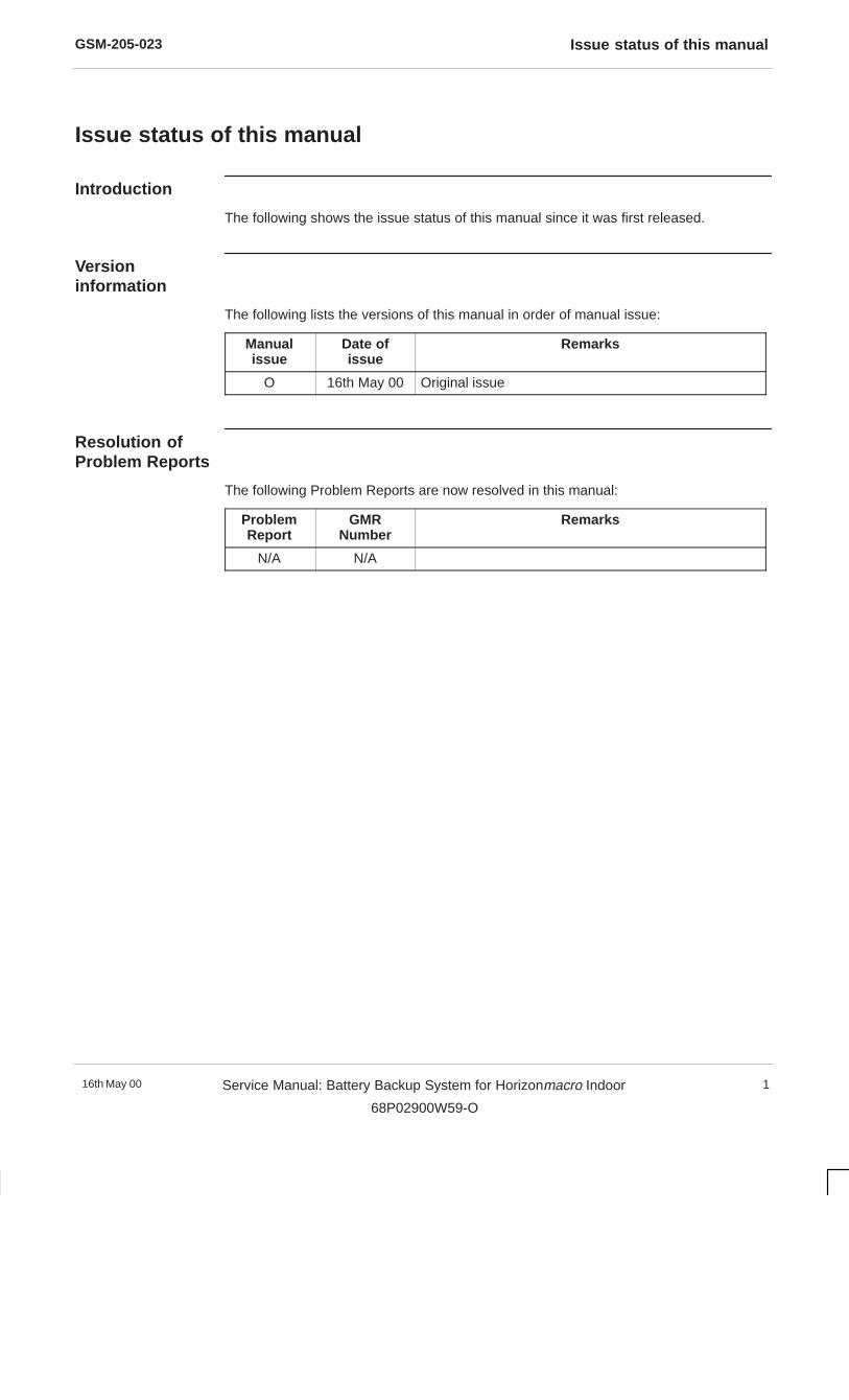
The following shows the issue status of this manual since it was first released.
Versioninformation
The following lists the versions of this manual in order of manual issue:
Manualissue
Date ofissue
Remarks
O 16th May 00 Original issue
Resolution ofProblem Reports
The following Problem Reports are now resolved in this manual:
ProblemReport
GMRNumber
Remarks
N/A N/A
GSM-205-023General information
16th May 002 Service Manual: Battery Backup System for Horizonmacro Indoor
68P02900W59-O
General information
Important notice
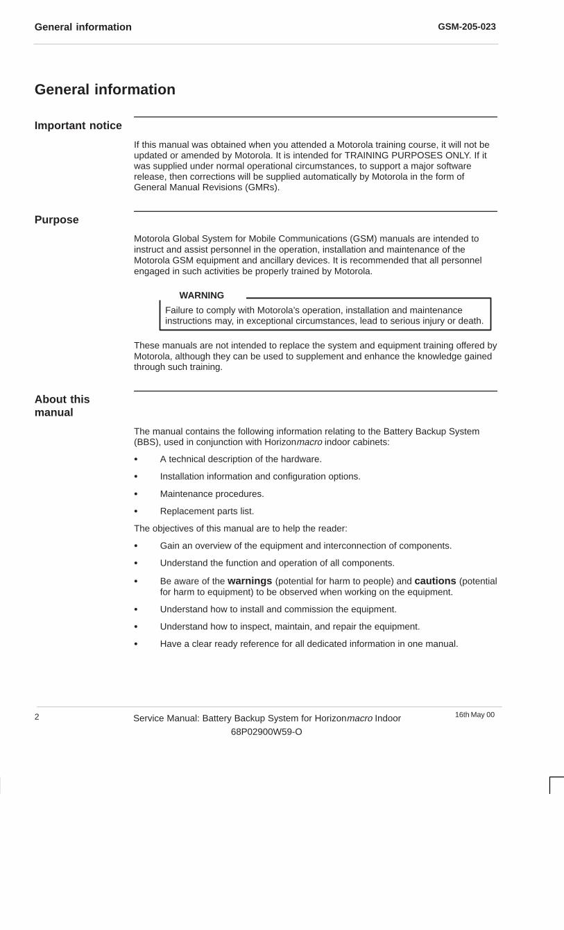
If this manual was obtained when you attended a Motorola training course, it will not beupdated or amended by Motorola. It is intended for TRAINING PURPOSES ONLY. If itwas supplied under normal operational circumstances, to support a major softwarerelease, then corrections will be supplied automatically by Motorola in the form ofGeneral Manual Revisions (GMRs).
Purpose
Motorola Global System for Mobile Communications (GSM) manuals are intended toinstruct and assist personnel in the operation, installation and maintenance of theMotorola GSM equipment and ancillary devices. It is recommended that all personnelengaged in such activities be properly trained by Motorola.
Failure to comply with Motorola’s operation, installation and maintenanceinstructions may, in exceptional circumstances, lead to serious injury or death.
WARNING
These manuals are not intended to replace the system and equipment training offered byMotorola, although they can be used to supplement and enhance the knowledge gainedthrough such training.
About thismanual
The manual contains the following information relating to the Battery Backup System(BBS), used in conjunction with Horizonmacro indoor cabinets:
� A technical description of the hardware.
� Installation information and configuration options.
� Maintenance procedures.
� Replacement parts list.
The objectives of this manual are to help the reader:
� Gain an overview of the equipment and interconnection of components.
� Understand the function and operation of all components.
� Be aware of the warnings (potential for harm to people) and cautions (potentialfor harm to equipment) to be observed when working on the equipment.
� Understand how to install and commission the equipment.
� Understand how to inspect, maintain, and repair the equipment.
� Have a clear ready reference for all dedicated information in one manual.
GSM-205-023 General information
16th May 00 Service Manual: Battery Backup System for Horizonmacro Indoor
68P02900W59-O
3
Cross references
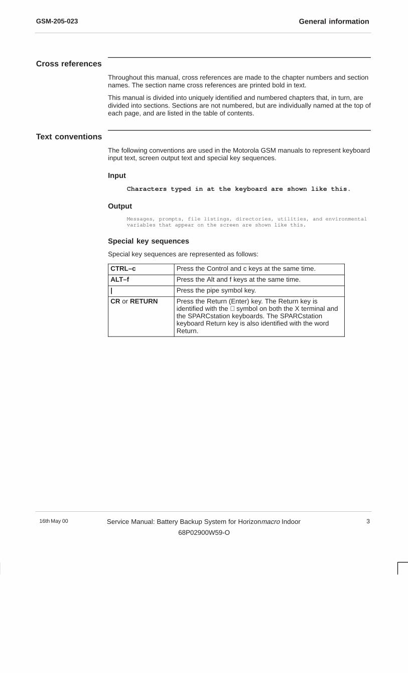
Throughout this manual, cross references are made to the chapter numbers and sectionnames. The section name cross references are printed bold in text.
This manual is divided into uniquely identified and numbered chapters that, in turn, aredivided into sections. Sections are not numbered, but are individually named at the top ofeach page, and are listed in the table of contents.
Text conventions
The following conventions are used in the Motorola GSM manuals to represent keyboardinput text, screen output text and special key sequences.
Input
Characters typed in at the keyboard are shown like this.
Output
Messages, prompts, file listings, directories, utilities, and environmentalvariables that appear on the screen are shown like this.
Special key sequences
Special key sequences are represented as follows:
CTRL–c Press the Control and c keys at the same time.
ALT–f Press the Alt and f keys at the same time.
| Press the pipe symbol key.
CR or RETURN Press the Return (Enter) key. The Return key isidentified with the ↵ symbol on both the X terminal andthe SPARCstation keyboards. The SPARCstationkeyboard Return key is also identified with the wordReturn.


GSM-205-023First aid in case of electric shock
16th May 004 Service Manual: Battery Backup System for Horizonmacro Indoor
68P02900W59-O
First aid in case of electric shock
Warning
Do not touch the victim with your bare hands until the electric circuit isbroken.Switch off. If this is not possible, protect yourself with dry insulatingmaterial and pull or push the victim clear of the conductor.
WARNING
Artificialrespiration
In the event of an electric shock it may be necessary to carry out artificial respiration.Send for medical assistance immediately.
Burns treatment
If the patient is also suffering from burns, then, without hindrance to artificial respiration,carry out the following:
1. Do not attempt to remove clothing adhering to the burn.
2. If help is available, or as soon as artificial respiration is no longer required, coverthe wound with a dry dressing.
3. Do not apply oil or grease in any form.

GSM-205-023 Reporting safety issues
16th May 00 Service Manual: Battery Backup System for Horizonmacro Indoor
68P02900W59-O
5
Reporting safety issues
Introduction
Whenever a safety issue arises, carry out the following procedure in all instances.Ensure that all site personnel are familiar with this procedure.
Procedure
Whenever a safety issue arises:
1. Make the equipment concerned safe, for example, by removing power.
2. Make no further attempt to tamper with the equipment.
3. Report the problem directly to GSM Customer Network Resolution Centre+44 (0)1793 430040 (telephone) and follow up with a written report by fax+44 (0)1793 430987 (fax).
4. Collect evidence from the equipment under the guidance of the Customer NetworkResolution Centre.
GSM-205-023Warnings and cautions
16th May 006 Service Manual: Battery Backup System for Horizonmacro Indoor
68P02900W59-O
Warnings and cautions
Introduction
The following describes how warnings and cautions are used in this manual and in allmanuals of the Motorola GSM manual set.
Warnings
Definition
A warning is used to alert the reader to possible hazards that could cause loss of life,physical injury, or ill health. This includes hazards introduced during maintenance, forexample, the use of adhesives and solvents, as well as those inherent in the equipment.
Example and format
Do not look directly into fibre optic cables or optical data in/out connectors.Laser radiation can come from either the data in/out connectors orunterminated fibre optic cables connected to data in/out connectors.
WARNING
Cautions
Definition
A caution means that there is a possibility of damage to systems, or individual items ofequipment within a system. However, this presents no danger to personnel.
Example and format
Do not use test equipment that is beyond its calibration due date when testingMotorola base stations.
CAUTION

GSM-205-023 General warnings
16th May 00 Service Manual: Battery Backup System for Horizonmacro Indoor
68P02900W59-O
7
General warnings
Introduction
Observe the following warnings during all phases of operation, installation andmaintenance of the equipment described in the Motorola GSM manuals. Failure tocomply with these warnings, or with specific warnings elsewhere in the Motorola GSMmanuals, violates safety standards of design, manufacture and intended use of theequipment. Motorola assumes no liability for the customer’s failure to comply with theserequirements.
Warning labelsPersonnel working with or operating Motorola equipment must comply with any warninglabels fitted to the equipment. Warning labels must not be removed, painted over orobscured in any way.
Specificwarnings
Warnings particularly applicable to the equipment are positioned on the equipment andwithin the text of this manual. These must be observed by all personnel at all times whenworking with the equipment, as must any other warnings given in text, on the illustrationsand on the equipment.
High voltageCertain Motorola equipment operates from a dangerous high voltage of 230 V ac singlephase or 415 V ac three phase mains which is potentially lethal. Therefore, the areaswhere the ac mains power is present must not be approached until the warnings andcautions in the text and on the equipment have been complied with.
To achieve isolation of the equipment from the ac supply, the mains input isolator mustbe set to off and locked.
Within the United Kingdom (UK) regard must be paid to the requirements of theElectricity at Work Regulations 1989. There may also be specific country legislationwhich need to be complied with, depending on where the equipment is used.
RF radiationHigh RF potentials and electromagnetic fields are present in the base station equipmentwhen in operation. Ensure that all transmitters are switched off when any antennaconnections have to be changed. Do not key transmitters connected to unterminatedcavities or feeders.
Refer to the following standards:
� ANSI IEEE C95.1-1991, IEEE Standard for Safety Levels with Respect to HumanExposure to Radio Frequency Electromagnetic Fields, 3kHz to 300GHz.
� CENELEC 95 ENV 50166-2, Human Exposure to Electromagnetic Fields HighFrequency (10kHz to 300GHz).
Laser radiationDo not look directly into fibre optic cables or optical data in/out connectors. Laserradiation can come from either the data in/out connectors or unterminated fibre opticcables connected to data in/out connectors.

GSM-205-023General warnings
16th May 008 Service Manual: Battery Backup System for Horizonmacro Indoor
68P02900W59-O
Liftingequipment
When dismantling heavy assemblies, or removing or replacing equipment, the competentresponsible person must ensure that adequate lifting facilities are available. Whereprovided, lifting frames must be used for these operations. When equipments have to bemanhandled, reference must be made to the Manual Handling of Loads Regulations1992 (UK) or to the relevant manual handling of loads legislation for the country in whichthe equipment is used.
Do not ...... substitute parts or modify equipment.
Because of the danger of introducing additional hazards, do not install substitute parts orperform any unauthorized modification of equipment. Contact Motorola if in doubt toensure that safety features are maintained.
Battery supplies
Do not wear earth straps when working with standby battery supplies.
Toxic material
Certain Motorola equipment incorporates components containing the highly toxic materialBeryllium or its oxide Beryllia or both. These materials are especially hazardous if:
� Beryllium materials are absorbed into the body tissues through the skin, mouth, ora wound.
� The dust created by breakage of Beryllia is inhaled.
� Toxic fumes are inhaled from Beryllium or Beryllia involved in a fire.
See the Beryllium health and safety precautions section for further information.

GSM-205-023 Human exposure to radio frequency energy (PCS1900 only)
16th May 00 Service Manual: Battery Backup System for Horizonmacro Indoor
68P02900W59-O
9
Human exposure to radio frequency energy (PCS1900 only)
IntroductionThis equipment is designed to generate and radiate radio frequency (RF) energy. Itshould be installed and maintained only by trained technicians. Licensees of the FederalCommunications Commission (FCC) using this equipment are responsible for insuringthat its installation and operation comply with FCC regulations designed to limit humanexposure to RF radiation in accordance with the American National Standards InstituteIEEE Standard C95.1-1991, IEEE Standard for Safety Levels with Respect to HumanExposure to Radio Frequency Electromagnetic Fields, 3kHz to 300GHz.
DefinitionsThis standard establishes two sets of maximum permitted exposure limits, one forcontrolled environments and another, that allows less exposure, for uncontrolledenvironments. These terms are defined by the standard, as follows:
Uncontrolled environment
Uncontrolled environments are locations where there is the exposure of individuals whohave no knowledge or control of their exposure. The exposures may occur in livingquarters or workplaces where there are no expectations that the exposure levels mayexceed those shown for uncontrolled environments in the table of maximum permittedexposure ceilings.
Controlled environmentControlled environments are locations where there is exposure that may be incurred bypersons who are aware of the potential for exposure as a concomitant of employment, byother cognizant persons, or as the incidental result of transient passage through areaswhere analysis shows the exposure levels may be above those shown for uncontrolledenvironments but do not exceed the values shown for controlled environments in thetable of maximum permitted exposure ceilings.
Maximumpermittedexposures
The maximum permitted exposures prescribed by the standard are set in terms ofdifferent parameters of effects, depending on the frequency generated by the equipmentin question. At the frequency range of this Personal Communication System equipment,1930-1970MHz, the maximum permitted exposure levels are set in terms of powerdensity, whose definition and relationship to electric field and magnetic field strengths aredescribed by the standard as follows:
Power density (S)
Power per unit area normal to the direction of propagation, usually expressed in units ofwatts per square metre (W/m2) or, for convenience, units such as milliwatts per squarecentimetre (mW/cm2). For plane waves, power density, electric field strength (E) andmagnetic field strength (H) are related by the impedance of free space, 377 ohms. Inparticular,
� ���
���� ���� ��
where E and H are expressed in units of V/m and A/m, respectively, and S in units ofW/m2. Although many survey instruments indicate power density units, the actualquantities measured are E or E2 or H or H2.
GSM-205-023Human exposure to radio frequency energy (PCS1900 only)
16th May 0010 Service Manual: Battery Backup System for Horizonmacro Indoor
68P02900W59-O
Maximumpermittedexposureceilings
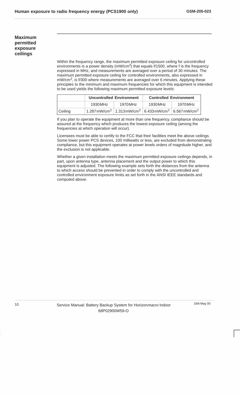
Within the frequency range, the maximum permitted exposure ceiling for uncontrolledenvironments is a power density (mW/cm2) that equals f/1500, where f is the frequencyexpressed in MHz, and measurements are averaged over a period of 30 minutes. Themaximum permitted exposure ceiling for controlled environments, also expressed inmW/cm2, is f/300 where measurements are averaged over 6 minutes. Applying theseprinciples to the minimum and maximum frequencies for which this equipment is intendedto be used yields the following maximum permitted exposure levels:
Uncontrolled Environment Controlled Environment
1930MHz 1970MHz 1930MHz 1970MHz
Ceiling 1.287mW/cm2 1.313mW/cm2 6.433mW/cm2 6.567mW/cm2
If you plan to operate the equipment at more than one frequency, compliance should beassured at the frequency which produces the lowest exposure ceiling (among thefrequencies at which operation will occur).
Licensees must be able to certify to the FCC that their facilities meet the above ceilings.Some lower power PCS devices, 100 milliwatts or less, are excluded from demonstratingcompliance, but this equipment operates at power levels orders of magnitude higher, andthe exclusion is not applicable.
Whether a given installation meets the maximum permitted exposure ceilings depends, inpart, upon antenna type, antenna placement and the output power to which thisequipment is adjusted. The following example sets forth the distances from the antennato which access should be prevented in order to comply with the uncontrolled andcontrolled environment exposure limits as set forth in the ANSI IEEE standards andcomputed above.
GSM-205-023 Human exposure to radio frequency energy (PCS1900 only)
16th May 00 Service Manual: Battery Backup System for Horizonmacro Indoor
68P02900W59-O
11
Examplecalculation
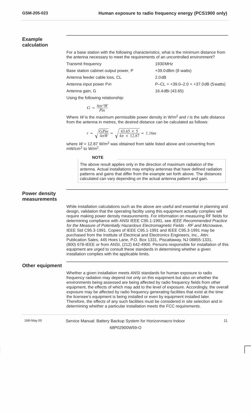
For a base station with the following characteristics, what is the minimum distance fromthe antenna necessary to meet the requirements of an uncontrolled environment?
Transmit frequency 1930MHz
Base station cabinet output power, P +39.0dBm (8 watts)
Antenna feeder cable loss, CL 2.0dB
Antenna input power Pin P–CL = +39.0–2.0 = +37.0dB (5watts)
Antenna gain, G 16.4dBi (43.65)
Using the following relationship:
� ������
���
Where W is the maximum permissible power density in W/m2 and r is the safe distancefrom the antenna in metres, the desired distance can be calculated as follows:
� �����
���� �
������ �
��� ������ � �����
where W = 12.87 W/m2 was obtained from table listed above and converting frommW/cm2 to W/m2.
The above result applies only in the direction of maximum radiation of theantenna. Actual installations may employ antennas that have defined radiationpatterns and gains that differ from the example set forth above. The distancescalculated can vary depending on the actual antenna pattern and gain.
NOTE
Power densitymeasurements
While installation calculations such as the above are useful and essential in planning anddesign, validation that the operating facility using this equipment actually complies willrequire making power density measurements. For information on measuring RF fields fordetermining compliance with ANSI IEEE C95.1-1991, see IEEE Recommended Practicefor the Measure of Potentially Hazardous Electromagnetic Fields - RF and Microwave,IEEE Std C95.3-1991. Copies of IEEE C95.1-1991 and IEEE C95.3-1991 may bepurchased from the Institute of Electrical and Electronics Engineers, Inc., Attn:Publication Sales, 445 Hoes Lane, P.O. Box 1331, Piscattaway, NJ 08855-1331,(800) 678-IEEE or from ANSI, (212) 642-4900. Persons responsible for installation of thisequipment are urged to consult these standards in determining whether a giveninstallation complies with the applicable limits.
Other equipmentWhether a given installation meets ANSI standards for human exposure to radiofrequency radiation may depend not only on this equipment but also on whether theenvironments being assessed are being affected by radio frequency fields from otherequipment, the effects of which may add to the level of exposure. Accordingly, the overallexposure may be affected by radio frequency generating facilities that exist at the timethe licensee’s equipment is being installed or even by equipment installed later.Therefore, the effects of any such facilities must be considered in site selection and indetermining whether a particular installation meets the FCC requirements.
GSM-205-023Beryllium health and safety precautions
16th May 0012 Service Manual: Battery Backup System for Horizonmacro Indoor
68P02900W59-O
Beryllium health and safety precautions
Introduction
Beryllium (Be), is a hard silver/white metal. It is stable in air, but burns brilliantly inOxygen.
With the exception of the naturally occurring Beryl ore (Beryllium Silicate), all Berylliumcompounds and Beryllium metal are potentially highly toxic.
Health issues
Beryllium Oxide is used within some components as an electrical insulator. Captive withinthe component it presents no health risk whatsoever. However, if the component shouldbe broken open and the Beryllium Oxide, which is in the form of dust, released, thereexists the potential for harm.
Inhalation
Inhalation of Beryllium Oxide can lead to a condition known as Berylliosis, the symptomsof Berylliosis are similar to Pneumonia and may be identified by all or any of thefollowing:
Mild poisoning causes fever, shortness of breath, and a cough that producesyellow/green sputum, or occasionally bloodstained sputum. Inflammation of the mucousmembranes of the nose, throat, and chest with discomfort, possibly pain, and difficultywith swallowing and breathing.
Severe poisoning causes chest pain and wheezing which may progress to severeshortness of breath due to congestion of the lungs. Incubation period for lung symptomsis 2-20 days.
Exposure to moderately high concentrations of Beryllium in air may produce a veryserious condition of the lungs. The injured person may become blue, feverish with rapidbreathing and raised pulse rate. Recovery is usual but may take several months. Therehave been deaths in the acute stage.
Chronic response. This condition is more truly a general one although the lungs aremainly affected. There may be lesions in the kidneys and the skin. Certain featuressupport the view that the condition is allergic. There is no relationship between thedegree of exposure and the severity of response and there is usually a time lag of up to10 years between exposure and the onset of the illness. Both sexes are equallysusceptible. The onset of the illness is insidious but only a small number of exposedpersons develop this reaction.
First aid
Seek immediate medical assistance. The casualty should be removed immediately fromthe exposure area and placed in a fresh air environment with breathing supported withOxygen where required. Any contaminated clothing should be removed. The casualtyshould be kept warm and at rest until medical aid arrives.

GSM-205-023 Beryllium health and safety precautions
16th May 00 Service Manual: Battery Backup System for Horizonmacro Indoor
68P02900W59-O
13
Skin contact
Possible irritation and redness at the contact area. Persistent itching and blisterformations can occur which usually resolve on removal from exposure.
First aid
Wash area thoroughly with soap and water. If skin is broken seek immediate medicalassistance.
Eye contact
May cause severe irritation, redness and swelling of eyelid(s) and inflammation of themucous membranes of the eyes.
First aid
Flush eyes with running water for at least 15 minutes. Seek medical assistance as soonas possible.
Handlingprocedures
Removal of components from printed circuit boards (PCBs) is to take place only atMotorola approved repair centres.
The removal station will be equipped with extraction equipment and all other protectiveequipment necessary for the safe removal of components containing Beryllium Oxide.
If during removal a component is accidently opened, the Beryllium Oxide dust is to bewetted into a paste and put into a container with a spatula or similar tool. The spatula/toolused to collect the paste is also to be placed in the container. The container is then to besealed and labelled. A suitable respirator is to be worn at all times during this operation.
Components which are successfully removed are to be placed in a separate bag, sealedand labelled.
Disposalmethods
Beryllium Oxide or components containing Beryllium Oxide are to be treated ashazardous waste. All components must be removed where possible from boards and putinto sealed bags labelled Beryllium Oxide components. These bags must be given to thesafety and environmental adviser for disposal.
Under no circumstances are boards or components containing Beryllium Oxide to be putinto the general waste skips or incinerated.
Product life cycleimplications
Motorola GSM and analogue equipment includes components containing Beryllium Oxide(identified in text as appropriate and indicated by warning labels on the equipment).These components require specific disposal measures as indicated in the preceding(Disposal methods) paragraph. Motorola will arrange for the disposal of all suchhazardous waste as part of its Total Customer Satisfaction philosophy and will arrangefor the most environmentally ‘friendly’ disposal available at that time.

GSM-205-023General cautions
16th May 0014 Service Manual: Battery Backup System for Horizonmacro Indoor
68P02900W59-O
General cautions
Introduction
Observe the following cautions during operation, installation and maintenance of theequipment described in the Motorola GSM manuals. Failure to comply with thesecautions or with specific cautions elsewhere in the Motorola GSM manuals may result indamage to the equipment. Motorola assumes no liability for the customer’s failure tocomply with these requirements.
Caution labels
Personnel working with or operating Motorola equipment must comply with any cautionlabels fitted to the equipment. Caution labels must not be removed, painted over orobscured in any way.
Specific cautions
Cautions particularly applicable to the equipment are positioned within the text of thismanual. These must be observed by all personnel at all times when working with theequipment, as must any other cautions given in text, on the illustrations and on theequipment.
Fibre optics
The bending radius of all fibre optic cables must not be less than 30 mm.
Static discharge
Motorola equipment contains CMOS devices that are vulnerable to static discharge.Although the damage caused by static discharge may not be immediately apparent,CMOS devices may be damaged in the long term due to static discharge caused bymishandling. Wear an approved earth strap when adjusting or handling digital boards.
See Devices sensitive to static for further information.

GSM-205-023 Devices sensitive to static
16th May 00 Service Manual: Battery Backup System for Horizonmacro Indoor
68P02900W59-O
15
Devices sensitive to static
Introduction
Certain metal oxide semiconductor (MOS) devices embody in their design a thin layer ofinsulation that is susceptible to damage from electrostatic charge. Such a charge appliedto the leads of the device could cause irreparable damage.
These charges can be built up on nylon overalls, by friction, by pushing the hands intohigh insulation packing material or by use of unearthed soldering irons.
MOS devices are normally despatched from the manufacturers with the leads shortedtogether, for example, by metal foil eyelets, wire strapping, or by inserting the leads intoconductive plastic foam. Provided the leads are shorted it is safe to handle the device.
Special handlingtechniques
In the event of one of these devices having to be replaced observe the followingprecautions when handling the replacement:
� Always wear an earth strap which must be connected to the electrostatic point(ESP) on the equipment.
� Leave the short circuit on the leads until the last moment. It may be necessary toreplace the conductive foam by a piece of wire to enable the device to be fitted.
� Do not wear outer clothing made of nylon or similar man made material. A cottonoverall is preferable.
� If possible work on an earthed metal surface. Wipe insulated plastic work surfaceswith an anti-static cloth before starting the operation.
� All metal tools should be used and when not in use they should be placed on anearthed surface.
� Take care when removing components connected to electrostatic sensitivedevices. These components may be providing protection to the device.
When mounted onto printed circuit boards (PCBs), MOS devices are normally lesssusceptible to electrostatic damage. However PCBs should be handled with care,preferably by their edges and not by their tracks and pins, they should be transferreddirectly from their packing to the equipment (or the other way around) and never leftexposed on the workbench.
GSM-205-023Motorola GSM manual set
16th May 0016 Service Manual: Battery Backup System for Horizonmacro Indoor
68P02900W59-O
Motorola GSM manual set
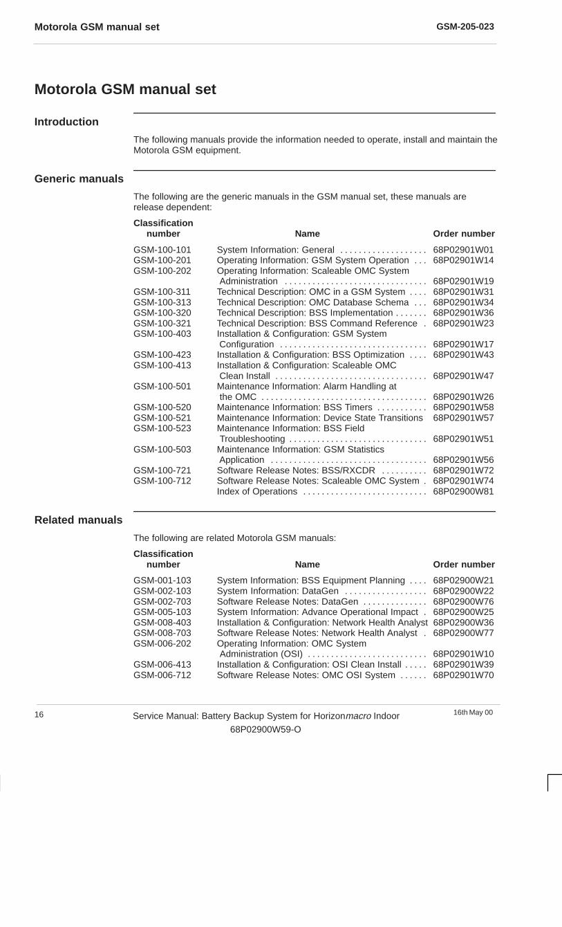
Introduction
The following manuals provide the information needed to operate, install and maintain theMotorola GSM equipment.
Generic manuals
The following are the generic manuals in the GSM manual set, these manuals arerelease dependent:
Classificationnumber Name Order number
GSM-100-101 System Information: General 68P02901W01. . . . . . . . . . . . . . . . . . . GSM-100-201 Operating Information: GSM System Operation 68P02901W14. . . GSM-100-202 Operating Information: Scaleable OMC System
Administration 68P02901W19. . . . . . . . . . . . . . . . . . . . . . . . . . . . . . . GSM-100-311 Technical Description: OMC in a GSM System 68P02901W31. . . . GSM-100-313 Technical Description: OMC Database Schema 68P02901W34. . . GSM-100-320 Technical Description: BSS Implementation 68P02901W36. . . . . . . GSM-100-321 Technical Description: BSS Command Reference 68P02901W23. GSM-100-403 Installation & Configuration: GSM System
Configuration 68P02901W17. . . . . . . . . . . . . . . . . . . . . . . . . . . . . . . . GSM-100-423 Installation & Configuration: BSS Optimization 68P02901W43. . . . GSM-100-413 Installation & Configuration: Scaleable OMC
Clean Install 68P02901W47. . . . . . . . . . . . . . . . . . . . . . . . . . . . . . . . . GSM-100-501 Maintenance Information: Alarm Handling at
the OMC 68P02901W26. . . . . . . . . . . . . . . . . . . . . . . . . . . . . . . . . . . . GSM-100-520 Maintenance Information: BSS Timers 68P02901W58. . . . . . . . . . . GSM-100-521 Maintenance Information: Device State Transitions 68P02901W57GSM-100-523 Maintenance Information: BSS Field
Troubleshooting 68P02901W51. . . . . . . . . . . . . . . . . . . . . . . . . . . . . . GSM-100-503 Maintenance Information: GSM Statistics
Application 68P02901W56. . . . . . . . . . . . . . . . . . . . . . . . . . . . . . . . . . GSM-100-721 Software Release Notes: BSS/RXCDR 68P02901W72. . . . . . . . . . GSM-100-712 Software Release Notes: Scaleable OMC System 68P02901W74.
Index of Operations 68P02900W81. . . . . . . . . . . . . . . . . . . . . . . . . . .
Related manuals
The following are related Motorola GSM manuals:
Classificationnumber Name Order number
GSM-001-103 System Information: BSS Equipment Planning 68P02900W21. . . . GSM-002-103 System Information: DataGen 68P02900W22. . . . . . . . . . . . . . . . . . GSM-002-703 Software Release Notes: DataGen 68P02900W76. . . . . . . . . . . . . . GSM-005-103 System Information: Advance Operational Impact 68P02900W25. GSM-008-403 Installation & Configuration: Network Health Analyst 68P02900W36GSM-008-703 Software Release Notes: Network Health Analyst 68P02900W77. GSM-006-202 Operating Information: OMC System
Administration (OSI) 68P02901W10. . . . . . . . . . . . . . . . . . . . . . . . . . GSM-006-413 Installation & Configuration: OSI Clean Install 68P02901W39. . . . . GSM-006-712 Software Release Notes: OMC OSI System 68P02901W70. . . . . .

GSM-205-023 Motorola GSM manual set
16th May 00 Service Manual: Battery Backup System for Horizonmacro Indoor
68P02900W59-O
17
Service manuals
The following are the service manuals in the GSM manual set, these manuals are notrelease dependent. The internal organization and makeup of service manual sets mayvary, they may consist of from one to four separate manuals, but they can all be orderedusing the overall catalogue number shown below:
Classificationnumber Name Order number
GSM-100-020 Service Manual: BTS 68P02901W37. . . . . . . . . . . . . . . . . . . . . . . . . . GSM-100-030 Service Manual: BSC/RXCDR 68P02901W38. . . . . . . . . . . . . . . . . . GSM-105-020 Service Manual: M-Cell2 68P02901W75. . . . . . . . . . . . . . . . . . . . . . . GSM-106-020 Service Manual: M-Cell6 68P02901W85. . . . . . . . . . . . . . . . . . . . . . . GSM-201-020 Service Manual: M-Cellcity and M-Cellcity+ 68P02901W95. . . . . . . GSM-202-020 Service Manual: M-Cellaccess 68P02901W65. . . . . . . . . . . . . . . . . . GSM-203-020 Service Manual: M-Cellarena 68P02902W36. . . . . . . . . . . . . . . . . . . GSM-206-020 Service Manual: M-Cellarenamacro 68P02902W15. . . . . . . . . . . . . . . GSM-205-020 Service Manual: Horizonmacro Indoor 68P02902W06. . . . . . . . . . . GSM-204-020 Service Manual: Horizonmacro Outdoor 68P02902W12. . . . . . . . . . GSM-207-020 Service Manual: Horizonoffice 68P02902W46. . . . . . . . . . . . . . . . . . GSM-101-SERIES ExCell4 Documentation Set 68P02900W50. . . . . . . . . . . . . . . . . . . . GSM-103-SERIES ExCell6 Documentation Set 68P02900W70. . . . . . . . . . . . . . . . . . . . GSM-102-SERIES TopCell Documentation Set (GSM900) 68P02901W80. . . . . . . . . . . GSM-104-SERIES TopCell Documentation Set (DCS1800) 68P02902W80. . . . . . . . . . GSM-200-SERIES M-Cellmicro Documentation Set 68P02901W90. . . . . . . . . . . . . . . . .
Classificationnumber
The classification number is used to identify the type and level of a manual. For example,manuals with the classification number GSM-100-2xx contain operating information.
Order number
The Motorola 68P order (catalogue) number is used to order manuals.
Orderingmanuals
All orders for Motorola manuals must be placed with your Motorola Local Office orRepresentative. Manuals are ordered using the order (catalogue) number. Remember,specify the manual issue required by quoting the correct suffix letter.
GSM-205-023GMR amendment
16th May 0018 Service Manual: Battery Backup System for Horizonmacro Indoor
68P02900W59-O
GMR amendment
Introduction toGMRs
Changes to a manual that occur after the printing date are incorporated into the manualusing General Manual Revisions (GMRs). GMRs are issued to correct Motorola manualsas and when required. A GMR has the same identity as the target manual. Each GMR isidentified by a number in a sequence that starts at 01 for each manual at each issue.GMRs are issued in the form of loose leaf pages, with a pink instruction sheet on thefront.
GMR procedure
When a GMR is received, check on the GMR amendment record page of this manualthat previous GMRs, if any, have been incorporated. If not, contact your administrator orMotorola Local Office to obtain the missing GMRs. Remove and replace pages in thismanual, as detailed on the GMR pink instruction sheet.

GSM-205-023 GMR amendment record
16th May 00 Service Manual: Battery Backup System for Horizonmacro Indoor
68P02900W59-O
19
GMR amendment record
Instructions
When a GMR is inserted in this manual, the amendment record below must be filled in torecord the insertion. Retain the pink instruction sheet that accompanies each GMR andinsert it in a suitable place in this manual for future reference.
Amendmentrecord
Record the insertion of GMRs in this manual in the following table:
GMR number Incorporated by (signature) Date
01
02
03
04
05
06
07
08
09
10
11
12
13
14
15
16
17
18
19
20
21
22
23
24
25

GSM-205-023GMR amendment record
16th May 0020 Service Manual: Battery Backup System for Horizonmacro Indoor
68P02900W59-O

16th May 00 Service Manual: Battery Backup System for Horizonmacro Indoor
68P02900W59-O
i
Chapter 1
Technical description of the
battery backup system

GSM-205-023
16th May 00ii Service Manual: Battery Backup System for Horizonmacro Indoor
68P02900W59-O
GSM-205-023
16th May 00 Service Manual: Battery Backup System for Horizonmacro Indoor
68P02900W59-O
iii
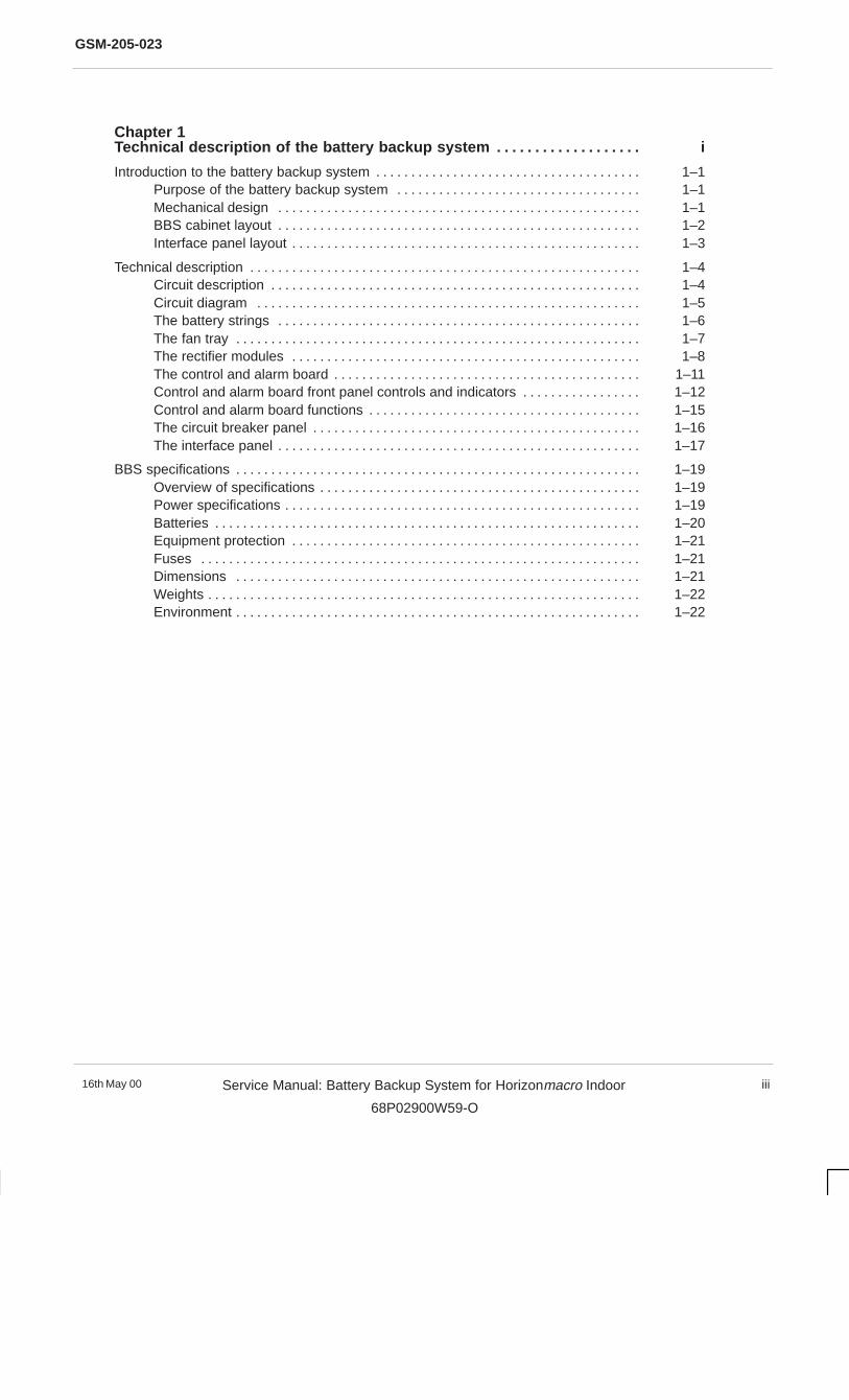
Chapter 1Technical description of the battery backup system i. . . . . . . . . . . . . . . . . . .
Introduction to the battery backup system 1–1. . . . . . . . . . . . . . . . . . . . . . . . . . . . . . . . . . . . . . Purpose of the battery backup system 1–1. . . . . . . . . . . . . . . . . . . . . . . . . . . . . . . . . . . Mechanical design 1–1. . . . . . . . . . . . . . . . . . . . . . . . . . . . . . . . . . . . . . . . . . . . . . . . . . . . BBS cabinet layout 1–2. . . . . . . . . . . . . . . . . . . . . . . . . . . . . . . . . . . . . . . . . . . . . . . . . . . . Interface panel layout 1–3. . . . . . . . . . . . . . . . . . . . . . . . . . . . . . . . . . . . . . . . . . . . . . . . . .
Technical description 1–4. . . . . . . . . . . . . . . . . . . . . . . . . . . . . . . . . . . . . . . . . . . . . . . . . . . . . . . . Circuit description 1–4. . . . . . . . . . . . . . . . . . . . . . . . . . . . . . . . . . . . . . . . . . . . . . . . . . . . . Circuit diagram 1–5. . . . . . . . . . . . . . . . . . . . . . . . . . . . . . . . . . . . . . . . . . . . . . . . . . . . . . . The battery strings 1–6. . . . . . . . . . . . . . . . . . . . . . . . . . . . . . . . . . . . . . . . . . . . . . . . . . . . The fan tray 1–7. . . . . . . . . . . . . . . . . . . . . . . . . . . . . . . . . . . . . . . . . . . . . . . . . . . . . . . . . . The rectifier modules 1–8. . . . . . . . . . . . . . . . . . . . . . . . . . . . . . . . . . . . . . . . . . . . . . . . . . The control and alarm board 1–11. . . . . . . . . . . . . . . . . . . . . . . . . . . . . . . . . . . . . . . . . . . . Control and alarm board front panel controls and indicators 1–12. . . . . . . . . . . . . . . . . Control and alarm board functions 1–15. . . . . . . . . . . . . . . . . . . . . . . . . . . . . . . . . . . . . . . The circuit breaker panel 1–16. . . . . . . . . . . . . . . . . . . . . . . . . . . . . . . . . . . . . . . . . . . . . . . The interface panel 1–17. . . . . . . . . . . . . . . . . . . . . . . . . . . . . . . . . . . . . . . . . . . . . . . . . . . .
BBS specifications 1–19. . . . . . . . . . . . . . . . . . . . . . . . . . . . . . . . . . . . . . . . . . . . . . . . . . . . . . . . . . Overview of specifications 1–19. . . . . . . . . . . . . . . . . . . . . . . . . . . . . . . . . . . . . . . . . . . . . . Power specifications 1–19. . . . . . . . . . . . . . . . . . . . . . . . . . . . . . . . . . . . . . . . . . . . . . . . . . . Batteries 1–20. . . . . . . . . . . . . . . . . . . . . . . . . . . . . . . . . . . . . . . . . . . . . . . . . . . . . . . . . . . . . Equipment protection 1–21. . . . . . . . . . . . . . . . . . . . . . . . . . . . . . . . . . . . . . . . . . . . . . . . . . Fuses 1–21. . . . . . . . . . . . . . . . . . . . . . . . . . . . . . . . . . . . . . . . . . . . . . . . . . . . . . . . . . . . . . . Dimensions 1–21. . . . . . . . . . . . . . . . . . . . . . . . . . . . . . . . . . . . . . . . . . . . . . . . . . . . . . . . . . Weights 1–22. . . . . . . . . . . . . . . . . . . . . . . . . . . . . . . . . . . . . . . . . . . . . . . . . . . . . . . . . . . . . . Environment 1–22. . . . . . . . . . . . . . . . . . . . . . . . . . . . . . . . . . . . . . . . . . . . . . . . . . . . . . . . . .

GSM-205-023
16th May 00iv Service Manual: Battery Backup System for Horizonmacro Indoor
68P02900W59-O
GSM-205-023 Introduction to the battery backup system
16th May 00 Service Manual: Battery Backup System for Horizonmacro Indoor
68P02900W59-O
1–1
Introduction to the battery backup system
Purpose of thebattery backupsystem
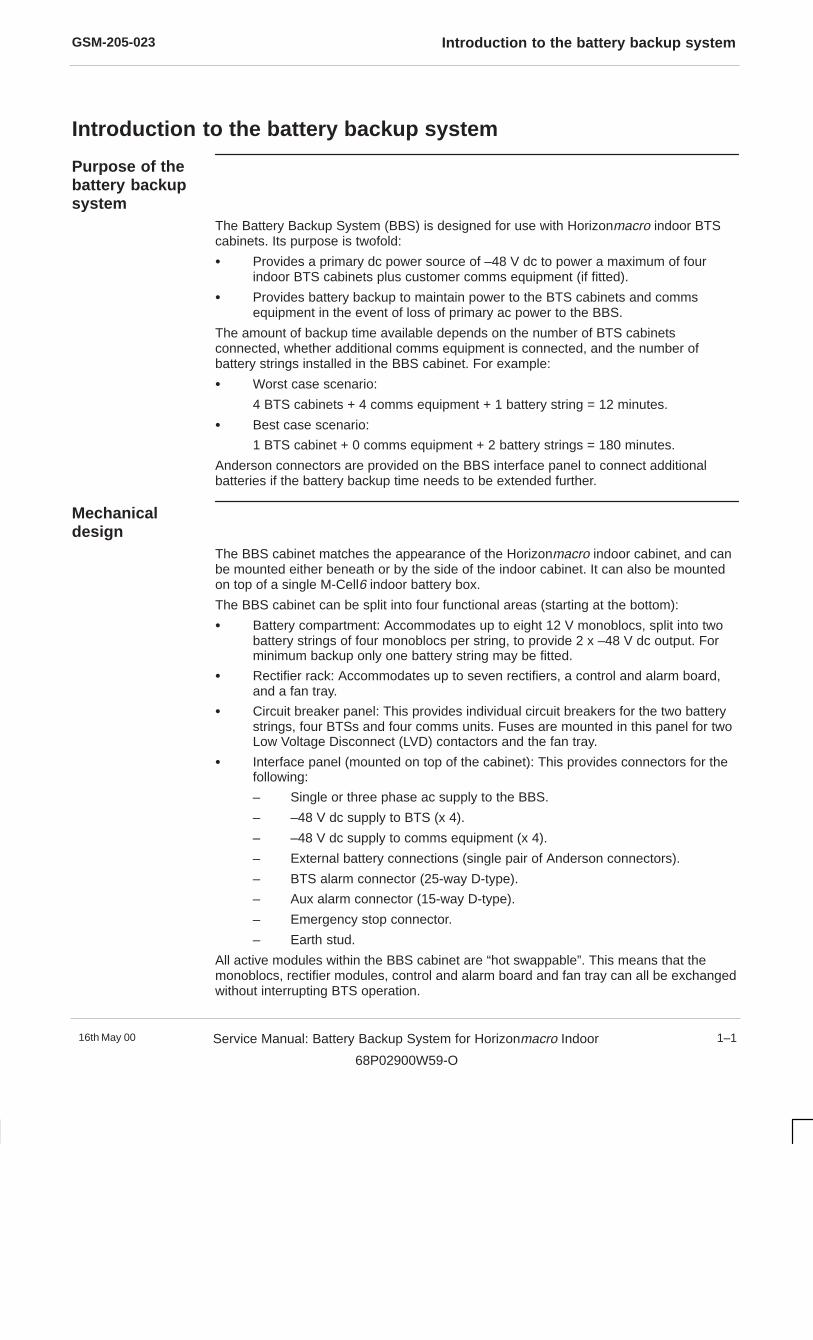
The Battery Backup System (BBS) is designed for use with Horizonmacro indoor BTScabinets. Its purpose is twofold:
� Provides a primary dc power source of –48 V dc to power a maximum of fourindoor BTS cabinets plus customer comms equipment (if fitted).
� Provides battery backup to maintain power to the BTS cabinets and commsequipment in the event of loss of primary ac power to the BBS.
The amount of backup time available depends on the number of BTS cabinetsconnected, whether additional comms equipment is connected, and the number ofbattery strings installed in the BBS cabinet. For example:
� Worst case scenario:
4 BTS cabinets + 4 comms equipment + 1 battery string = 12 minutes.
� Best case scenario:
1 BTS cabinet + 0 comms equipment + 2 battery strings = 180 minutes.
Anderson connectors are provided on the BBS interface panel to connect additionalbatteries if the battery backup time needs to be extended further.
Mechanicaldesign
The BBS cabinet matches the appearance of the Horizonmacro indoor cabinet, and canbe mounted either beneath or by the side of the indoor cabinet. It can also be mountedon top of a single M-Cell6 indoor battery box.
The BBS cabinet can be split into four functional areas (starting at the bottom):
� Battery compartment: Accommodates up to eight 12 V monoblocs, split into twobattery strings of four monoblocs per string, to provide 2 x –48 V dc output. Forminimum backup only one battery string may be fitted.
� Rectifier rack: Accommodates up to seven rectifiers, a control and alarm board,and a fan tray.
� Circuit breaker panel: This provides individual circuit breakers for the two batterystrings, four BTSs and four comms units. Fuses are mounted in this panel for twoLow Voltage Disconnect (LVD) contactors and the fan tray.
� Interface panel (mounted on top of the cabinet): This provides connectors for thefollowing:
– Single or three phase ac supply to the BBS.
– –48 V dc supply to BTS (x 4).
– –48 V dc supply to comms equipment (x 4).
– External battery connections (single pair of Anderson connectors).
– BTS alarm connector (25-way D-type).
– Aux alarm connector (15-way D-type).
– Emergency stop connector.
– Earth stud.
All active modules within the BBS cabinet are “hot swappable”. This means that themonoblocs, rectifier modules, control and alarm board and fan tray can all be exchangedwithout interrupting BTS operation.

GSM-205-023Introduction to the battery backup system
16th May 001–2 Service Manual: Battery Backup System for Horizonmacro Indoor
68P02900W59-O
BBS cabinetlayout
Figure 1-1 shows the layout inside the BBS cabinet.
INTERFACE PANEL
MONOBLOCS
FAN TRAY
RECTIFIERS
CIRCUIT BREAKERPANEL
CONTROLAND ALARM
BOARD
AC SUPPLY CONNECTOR(COVER REMOVED)
Figure 1-1 Fully equipped BBS cabinet layout (air inlet and battery cover removed)
GSM-205-023 Introduction to the battery backup system
16th May 00 Service Manual: Battery Backup System for Horizonmacro Indoor
68P02900W59-O
1–3
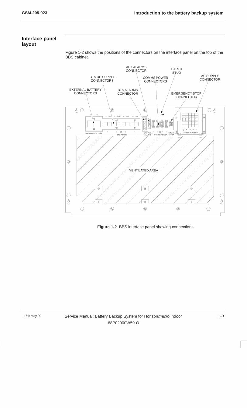
Interface panellayout
Figure 1-2 shows the positions of the connectors on the interface panel on the top of theBBS cabinet.
EXTERNAL BATTERYCONNECTORS
BTS ALARMSCONNECTOR
AUX ALARMSCONNECTOR
AC SUPPLYCONNECTORCOMMS POWER
CONNECTORS
EMERGENCY STOP CONNECTOR
EARTHSTUD
BTS DC SUPPLYCONNECTORS
VENTILATED AREA
EXTERNAL BATTERYBTS POWER
BTS AUXALARMS COMMS POWER
EMERG.STOP
AC INPUT POWER
Figure 1-2 BBS interface panel showing connections
GSM-205-023Technical description
16th May 001–4 Service Manual: Battery Backup System for Horizonmacro Indoor
68P02900W59-O
Technical description
Circuitdescription
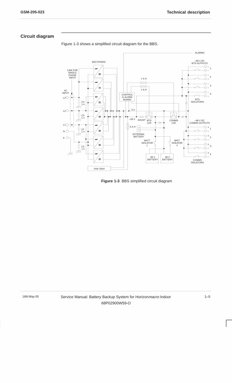
AC input power, provided by a single phase or three phase supply, is fed to a bank of upto seven rectifiers. When a single phase ac input is used, all rectifiers are supplied from acommon supply rail. When a three phase input is used the rectifiers are divided into threegroups and each group supplied by a different supply phase.
The rectifiers convert the ac input to a regulated dc output, which is fed to the BTS andComms connectors on the interface panel via the BTS and COMMS LVD contactors.Circuit breakers are fitted between the LVDs and the dc output connectors to provideindividual isolation facilities for each BTS and comms equipment dc supply.
Backup batteries are connected to the dc supply circuit through two circuit breakers,which individually isolate the two battery strings. Under normal operating conditions, thebatteries are float charged from the dc supply. If there is an interruption to the ac supply,power for the BTSs and comms equipment is automatically supplied directly from thebatteries with no interruption. Once the ac supply is restored, dc power from the rectifiersis again fed to the BTSs and comms equipment.
The control and alarm board regulates the charge rate of the batteries by controlling theoutput of the rectifiers. When operating on battery backup power, the control and alarmboard monitors the dc output voltage level. An LVD Imminent alarm is issued when thebattery voltage falls to 42.5 V (+/–0.5 V) to warn of an impending LVD disconnect. If theoutput voltage drops below 41 V (+/–0.5 V), the BTS LVD contactor opens to disconnectthe dc supply to the BTSs to prevent deep discharge of the batteries. If the outputvoltage drops further to 39.5 V (+/–0.5 V), the COMMS LVD contactor opens todisconnect the dc supply to the system. Both LVD contactors close automatically once acpower to the BBS cabinet is restored.
Remote alarm and signal connections are available from the BBS interface panel to thedesignated master Horizonmacro indoor BTS.
GSM-205-023 Technical description
16th May 00 Service Manual: Battery Backup System for Horizonmacro Indoor
68P02900W59-O
1–5
Circuit diagram
Figure 1-3 shows a simplified circuit diagram for the BBS.
ACINPUT
L3
L2
L1
N
E
FAN TRAY
C41 n
C31 n
C11 n
C21 n
RECTIFIERS
1 A H
1 A H
0 V
–48 V SHUNT
5 A H
BTSLVD
COMMSLVD
EXTERNALBATTERY
BATTISOLATOR
1
BATTISOLATOR
2
48 VBATTERY
48 VBATTERY
–48 V DCBTS OUTPUTS
BTSISOLATORS
–48 V DCCOMMS OUTPUTS
COMMSISOLATORS
1
2
3
4
1
2
3
4
CONTROL& ALARMBOARD
LINK FORSINGLEPHASEINPUT
ALARMS
Figure 1-3 BBS simplified circuit diagram
GSM-205-023Technical description
16th May 001–6 Service Manual: Battery Backup System for Horizonmacro Indoor
68P02900W59-O
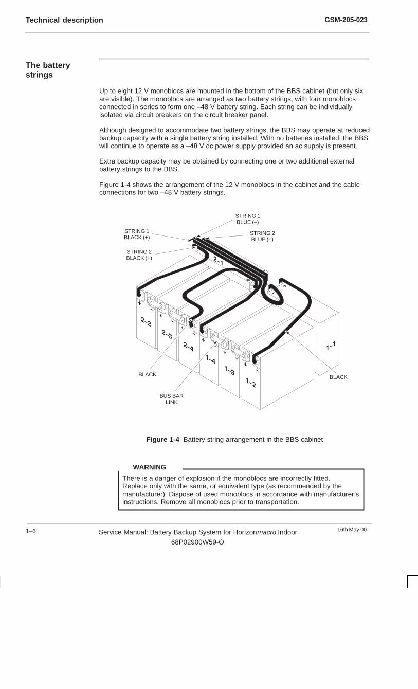
The batterystrings
Up to eight 12 V monoblocs are mounted in the bottom of the BBS cabinet (but only sixare visible). The monoblocs are arranged as two battery strings, with four monoblocsconnected in series to form one –48 V battery string. Each string can be individuallyisolated via circuit breakers on the circuit breaker panel.
Although designed to accommodate two battery strings, the BBS may operate at reducedbackup capacity with a single battery string installed. With no batteries installed, the BBSwill continue to operate as a –48 V dc power supply provided an ac supply is present.
Extra backup capacity may be obtained by connecting one or two additional externalbattery strings to the BBS.
Figure 1-4 shows the arrangement of the 12 V monoblocs in the cabinet and the cableconnections for two –48 V battery strings.
BLACKBLACK
STRING 2BLACK (+)
STRING 1BLACK (+)
STRING 1BLUE (–)
STRING 2BLUE (–)
BUS BARLINK
Figure 1-4 Battery string arrangement in the BBS cabinet
There is a danger of explosion if the monoblocs are incorrectly fitted.Replace only with the same, or equivalent type (as recommended by themanufacturer). Dispose of used monoblocs in accordance with manufacturer’sinstructions. Remove all monoblocs prior to transportation.
WARNING
GSM-205-023 Technical description
16th May 00 Service Manual: Battery Backup System for Horizonmacro Indoor
68P02900W59-O
1–7
The fan tray
The fan tray is mounted immediately above the battery compartment and providescooling for the rectifiers. The tray contains eight 48 V dc fans powered from a dc supplybus via a fuse mounted on the circuit breaker panel.
The fans have three speed settings. Initially they run at full speed, but after five seconds,control of fan speed is determined by the incoming ambient air temperature, which ismonitored by a sensor within the fan tray. At up to room temperature, the fans operate atthe lowest speed. Above room temperature and up to 45 �C, the fans operate at theintermediate speed. If the temperature rises above 45 �C, the fans operate at full speed.
On failure of any fan, the fans run at full speed, regardless of ambient temperature, tocompensate for the loss of airflow.
The control and alarm board monitors the operation of the fans. If one fan fails, a minorSingle Fan Fail alarm condition is signalled to the master BTS cabinet by the control andalarm board and an LED on the module front panel is illuminated. If more than one fanfails, both minor Single Fan Fail and major > 1 Fan Fail alarm conditions are signalled tothe master BTS and LEDs reporting both conditions are illuminated on the control andalarm board front panel.
The control and alarm board ignores all fan fail signals when the ac supply to the BBS isnot present.
GSM-205-023Technical description
16th May 001–8 Service Manual: Battery Backup System for Horizonmacro Indoor
68P02900W59-O
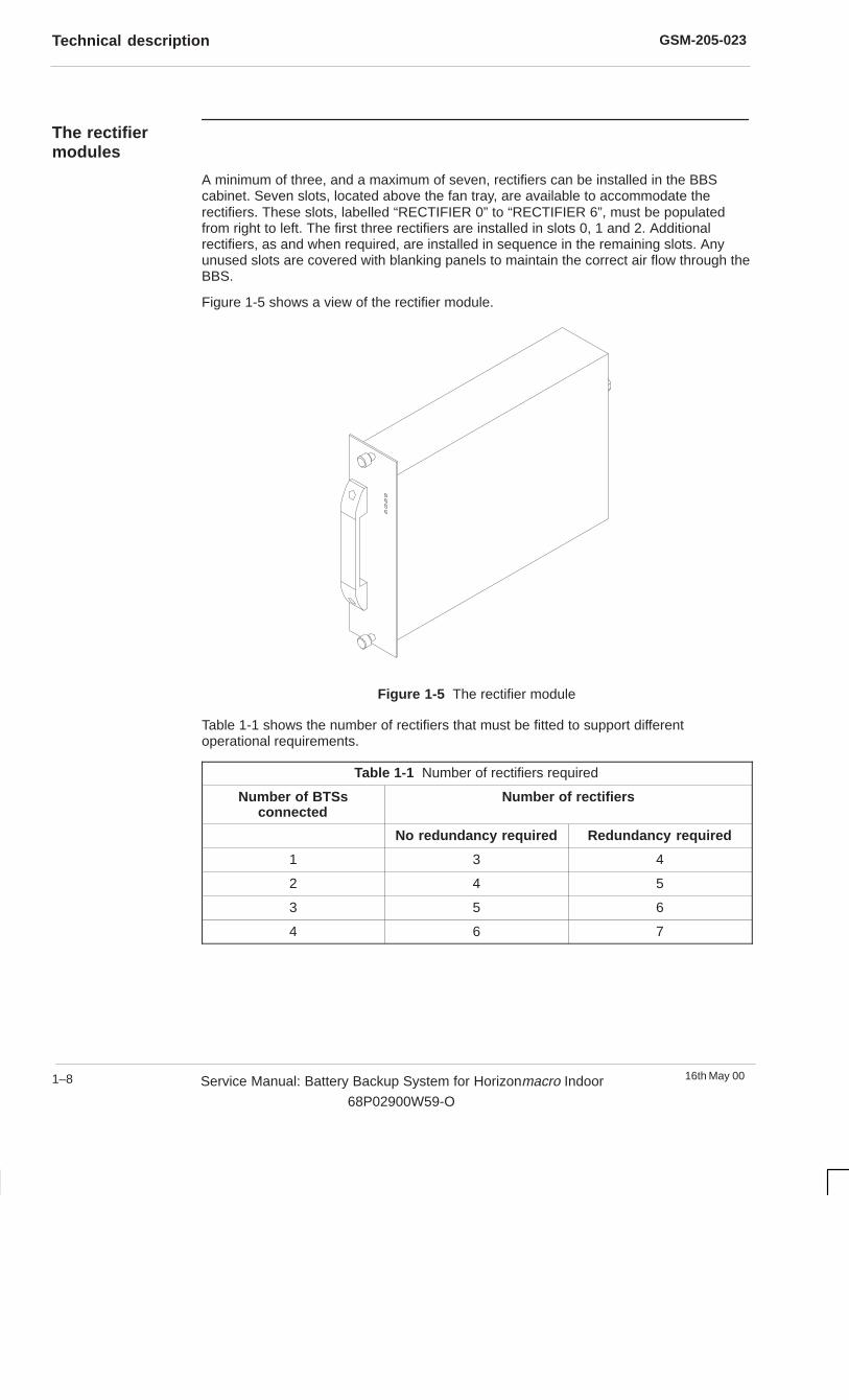
The rectifiermodules
A minimum of three, and a maximum of seven, rectifiers can be installed in the BBScabinet. Seven slots, located above the fan tray, are available to accommodate therectifiers. These slots, labelled “RECTIFIER 0” to “RECTIFIER 6”, must be populatedfrom right to left. The first three rectifiers are installed in slots 0, 1 and 2. Additionalrectifiers, as and when required, are installed in sequence in the remaining slots. Anyunused slots are covered with blanking panels to maintain the correct air flow through theBBS.
Figure 1-5 shows a view of the rectifier module.
Figure 1-5 The rectifier module
Table 1-1 shows the number of rectifiers that must be fitted to support differentoperational requirements.
Table 1-1 Number of rectifiers required
Number of BTSsconnected
Number of rectifiers
No redundancy required Redundancy required
1 3 4
2 4 5
3 5 6
4 6 7
GSM-205-023 Technical description
16th May 00 Service Manual: Battery Backup System for Horizonmacro Indoor
68P02900W59-O
1–9
Rectifier functional description
The rectifier is a power factor-corrected, wide input, ac power supply module. Eachmodule is a switching type ac/dc power converter with the following regulated dc output:
� –54 V at 22.0 A (nominal).
� 1200 W (nominal).
The ac supply is fed to the rectifiers via the interface panel on the top of the BBS cabinet.
When the BBS is supplied from a single phase ac input, the rectifiers are all suppliedfrom a single source. When the BBS is supplied from a three phase ac input, therectifiers are divided into three groups and each group supplied by a different phase ofthe ac input. For example, with all seven rectifiers fitted, the ac input is connected asfollows:
Phase 1 (L1) supplies rectifiers 0, 3 and 6
Phase 2 (L2) supplies rectifiers 1, and 4
Phase 3 (L3) supplies rectifiers 2 and 5
The regulated dc output is fed through circuit breakers on the circuit breaker panel to theHorizonmacro indoor BTS cabinets and also to the comms power connectors, via theCOMMS LVD contactor.
The outputs of each rectifier are connected in parallel and all rectifiers in the cabinetactively share the load.
Front panel LEDs
There are four LEDs mounted on the front of each rectifier, which indicate the following:
� I/P HEALTHY (yellow) - lit when the input voltage is present and within specifiedlimits.
� OVERVOLTAGE (red) - lit when the rectifier has shut down due to an outputvoltage in excess of –59.9 V dc.
� OVERCURRENT (red) - lit when the rectifier is in current limit and delivering acurrent in the range 22 A to 24 A. The LED is normally unlit, but when lit does notnecessarily indicate the existence of a fault as this may be due to recharging of thebatteries after an ac supply interruption.
� O/P HEALTHY (green) - lit when the output voltage is present and within specifiedlimits (–39 to –59.9 V dc).
GSM-205-023Technical description
16th May 001–10 Service Manual: Battery Backup System for Horizonmacro Indoor
68P02900W59-O
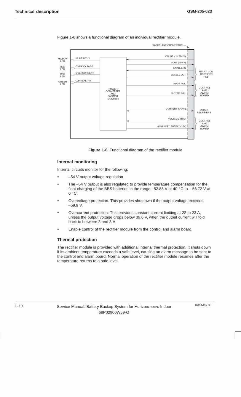
Figure 1-6 shows a functional diagram of an individual rectifier module.
I/P HEALTHY
OUTPUT FAIL
INPUT FAIL
BACKPLANE CONNECTOR
REDLED
YELLOWLED
VIN (88 V to 264 V)
POWERCONVERTER
ANDSYSTEM
MONITOR
VOLTAGE TRIM
VOUT (–55 V)
ENABLE IN
O/P HEALTHY
OVERVOLTAGE
OVERCURRENTREDLED
GREENLED
CONTROLAND
ALARMBOARD
CURRENT SHARE OTHERRECTIFIERS
AUXILIARY SUPPLY (12V)
ENABLE OUTRELAY 1 ON RECTIFIER
PCB
CONTROLAND
ALARMBOARD
Figure 1-6 Functional diagram of the rectifier module
Internal monitoring
Internal circuits monitor for the following:
� –54 V output voltage regulation.
� The –54 V output is also regulated to provide temperature compensation for thefloat charging of the BBS batteries in the range –52.88 V at 40 �C to –56.72 V at0 �C.
� Overvoltage protection. This provides shutdown if the output voltage exceeds–59.9 V.
� Overcurrent protection. This provides constant current limiting at 22 to 23 A,unless the output voltage drops below 39.6 V, when the output current will foldback to between 3 and 8 A.
� Enable control of the rectifier module from the control and alarm board.
Thermal protection
The rectifier module is provided with additional internal thermal protection. It shuts downif its ambient temperature exceeds a safe level, causing an alarm message to be sent tothe control and alarm board. Normal operation of the rectifier module resumes after thetemperature returns to a safe level.
GSM-205-023 Technical description
16th May 00 Service Manual: Battery Backup System for Horizonmacro Indoor
68P02900W59-O
1–11
The control andalarm board
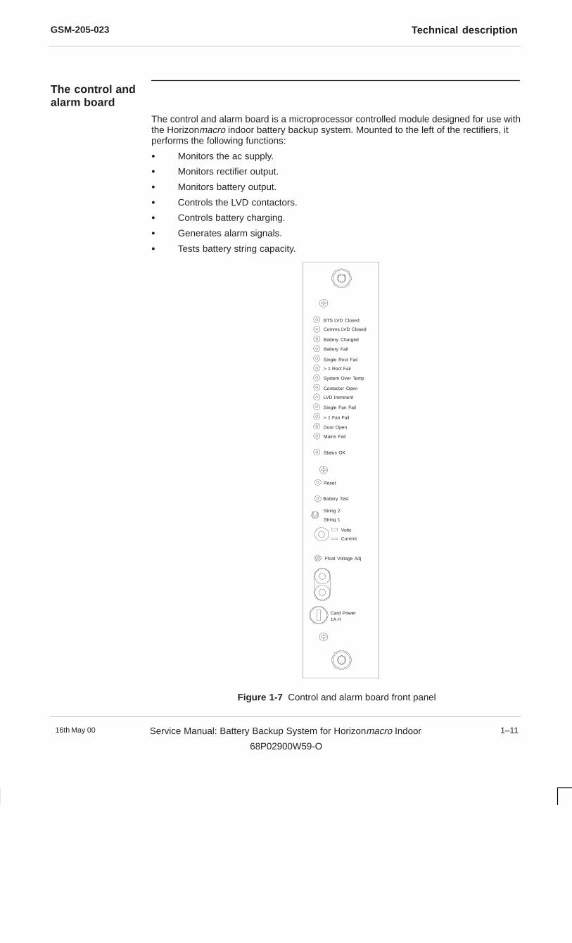
The control and alarm board is a microprocessor controlled module designed for use withthe Horizonmacro indoor battery backup system. Mounted to the left of the rectifiers, itperforms the following functions:
� Monitors the ac supply.
� Monitors rectifier output.
� Monitors battery output.
� Controls the LVD contactors.
� Controls battery charging.
� Generates alarm signals.
� Tests battery string capacity.
BTS LVD Closed
Comms LVD Closed
Battery Charged
Battery Fail
Single Rect Fail
> 1 Rect Fail
System Over Temp
Contactor Open
LVD Imminent
Single Fan Fail
> 1 Fan Fail
Door Open
Mains Fail
Status OK
Reset
Battery Test
String 2
String 1
Volts
Current
Float Voltage Adj
Card Power1A H
Figure 1-7 Control and alarm board front panel
GSM-205-023Technical description
16th May 001–12 Service Manual: Battery Backup System for Horizonmacro Indoor
68P02900W59-O
Control andalarm board frontpanel controlsand indicators
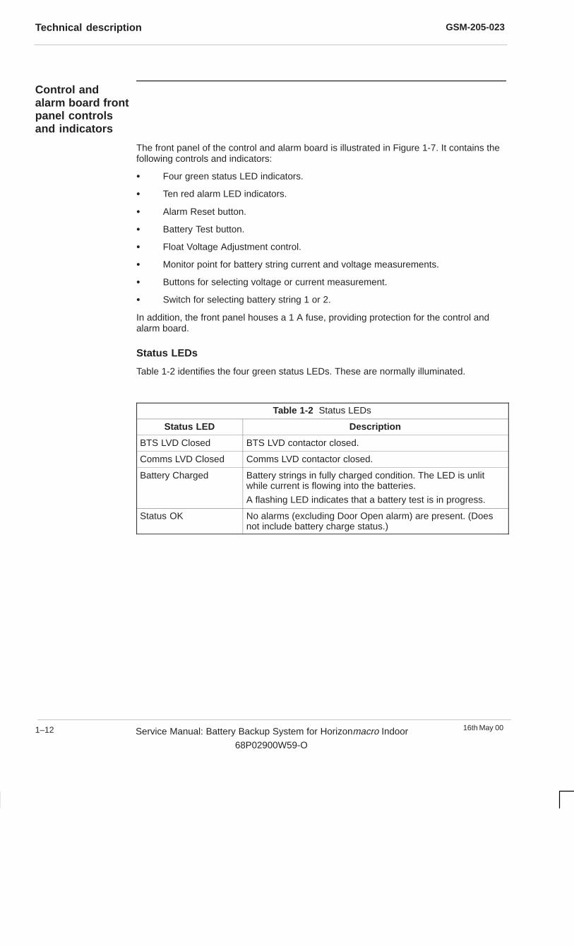
The front panel of the control and alarm board is illustrated in Figure 1-7. It contains thefollowing controls and indicators:
� Four green status LED indicators.
� Ten red alarm LED indicators.
� Alarm Reset button.
� Battery Test button.
� Float Voltage Adjustment control.
� Monitor point for battery string current and voltage measurements.
� Buttons for selecting voltage or current measurement.
� Switch for selecting battery string 1 or 2.
In addition, the front panel houses a 1 A fuse, providing protection for the control andalarm board.
Status LEDs
Table 1-2 identifies the four green status LEDs. These are normally illuminated.
Table 1-2 Status LEDs
Status LED Description
BTS LVD Closed BTS LVD contactor closed.
Comms LVD Closed Comms LVD contactor closed.
Battery Charged Battery strings in fully charged condition. The LED is unlitwhile current is flowing into the batteries.
A flashing LED indicates that a battery test is in progress.
Status OK No alarms (excluding Door Open alarm) are present. (Doesnot include battery charge status.)
GSM-205-023 Technical description
16th May 00 Service Manual: Battery Backup System for Horizonmacro Indoor
68P02900W59-O
1–13
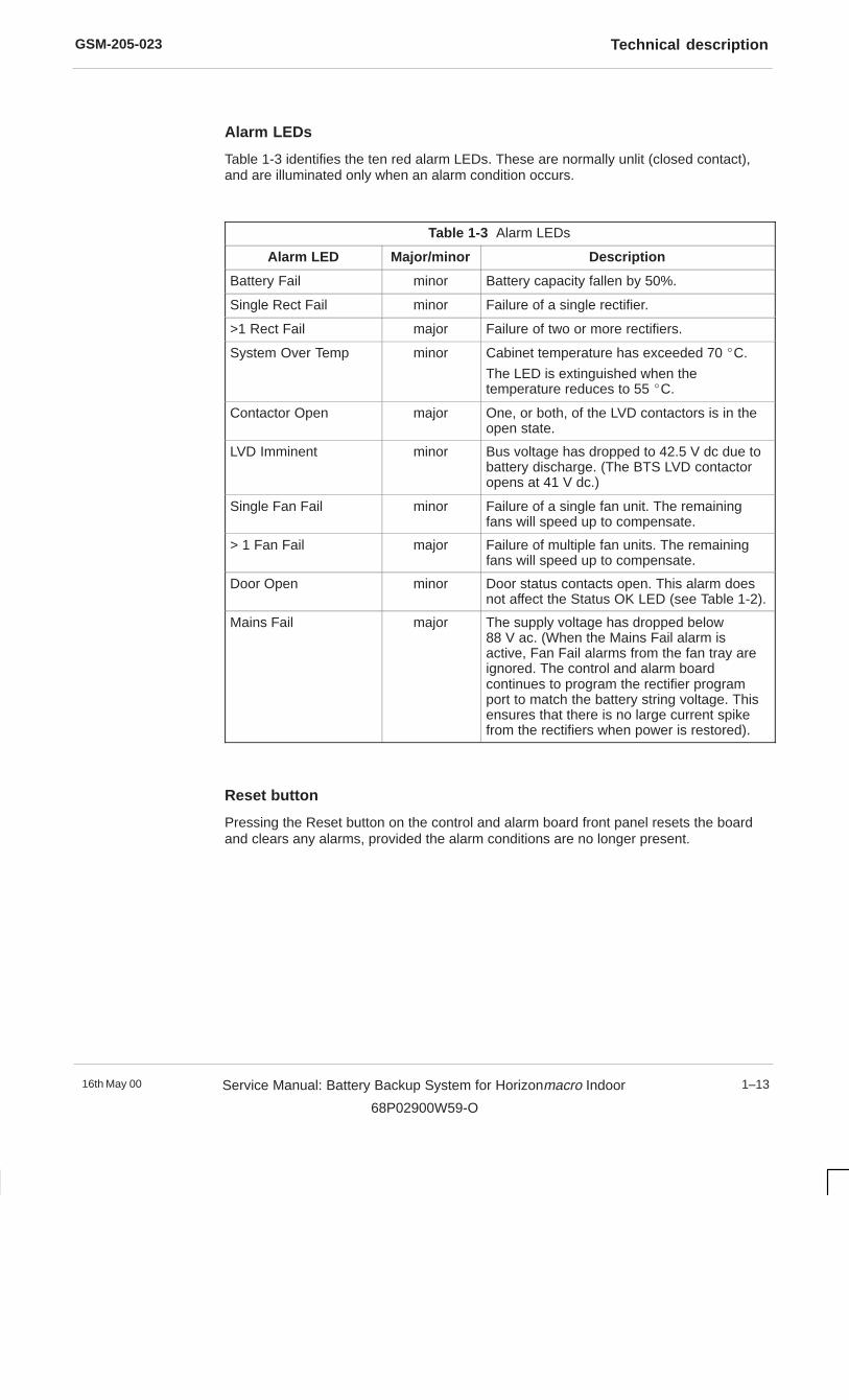
Alarm LEDs
Table 1-3 identifies the ten red alarm LEDs. These are normally unlit (closed contact),and are illuminated only when an alarm condition occurs.
Table 1-3 Alarm LEDs
Alarm LED Major/minor Description
Battery Fail minor Battery capacity fallen by 50%.
Single Rect Fail minor Failure of a single rectifier.
>1 Rect Fail major Failure of two or more rectifiers.
System Over Temp minor Cabinet temperature has exceeded 70 �C.
The LED is extinguished when thetemperature reduces to 55 �C.
Contactor Open major One, or both, of the LVD contactors is in theopen state.
LVD Imminent minor Bus voltage has dropped to 42.5 V dc due tobattery discharge. (The BTS LVD contactoropens at 41 V dc.)
Single Fan Fail minor Failure of a single fan unit. The remainingfans will speed up to compensate.
> 1 Fan Fail major Failure of multiple fan units. The remainingfans will speed up to compensate.
Door Open minor Door status contacts open. This alarm doesnot affect the Status OK LED (see Table 1-2).
Mains Fail major The supply voltage has dropped below88 V ac. (When the Mains Fail alarm isactive, Fan Fail alarms from the fan tray areignored. The control and alarm boardcontinues to program the rectifier programport to match the battery string voltage. Thisensures that there is no large current spikefrom the rectifiers when power is restored).
Reset button
Pressing the Reset button on the control and alarm board front panel resets the boardand clears any alarms, provided the alarm conditions are no longer present.

GSM-205-023Technical description
16th May 001–14 Service Manual: Battery Backup System for Horizonmacro Indoor
68P02900W59-O
Battery test
The control and alarm board can perform a battery test which, when initiated, reducesthe output from the rectifiers to 43 V dc (5 V below the battery voltage). This results inany load connected to the system to be fed directly from the batteries. Hence, batterycapacity can be calculated by continuously monitoring battery current, voltage and time.
Battery capacity is dependent on the number of battery strings connected. A four-positiondipswitch (SW3) mounted internally on the control and alarm board allows selection of 1,2, 3 or 4 battery strings of 65 amp-hours each. The switch default setting is 2, referring tothe two –48 V dc internal battery strings. Positions 3 or 4 may be selected if additionalexternal battery strings are connected.
The battery test may be initiated by one of the following methods:
� Automatically carried out by the control and alarm board on a monthly basis.
� Locally, by operation of the front panel Battery Test switch.
� Remotely, via the Battery Test Initiate connection (see Table 1-5).
The green Battery Charged LED on the control and alarm board front panel flashes whenthe unit is undergoing a battery test.
If the battery voltage remains above 44 V for the duration of the test, the batteries areconsidered good, the test is terminated and the system returns to normal operation. If thebattery voltage falls to 44 V, then the test is terminated prematurely, a FAIL signal isindicated on the AUX ALARMS connector and the Battery Fail LED is illuminated. Ifneither a PASS or FAIL signal is produced after testing, then the control and alarm boardautomatically initiates another test, every five hours, until a PASS or FAIL result isachieved.
The battery test facility is not available if the batteries are not charged, or if any alarmcondition is present other than the Door Open or Battery Fail alarms. The same alarmsoccurring at any time during a test cause the test to be terminated immediately and thesystem returns to normal operation with no battery test result. If the battery test is notvalid when an automatic monthly test is attempted, the alarms module will retry to initiatethe test every five hours until it can proceed.
Float voltage adjustment
Adjustment of the battery float (charging) voltage is not normally required. However, ifrequired, adjustment can be carried out using the Float Voltage Adj potentiometer on thefront panel of the control and alarm board. However, this must only be adjusted when thegreen Battery Charged LED is illuminated.
If the Battery Charged LED is unlit, it indicates that the batteries are not fullycharged. The control and alarm board continually adjusts the rectifier output toquickly recharge the batteries. Any adjustment of the Float Voltage Adjpotentiometer at this point is opposed by the control and alarm board.
NOTE
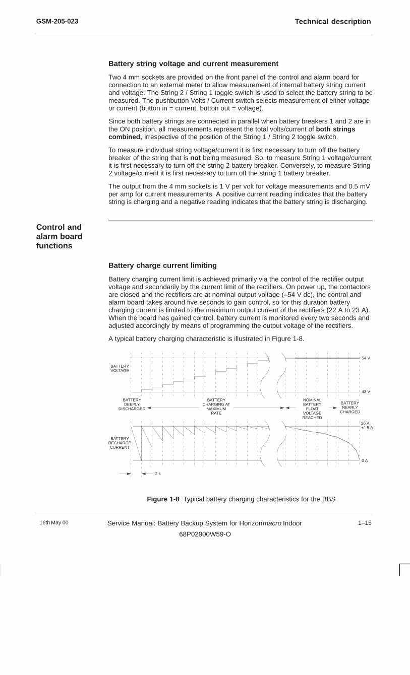
GSM-205-023 Technical description
16th May 00 Service Manual: Battery Backup System for Horizonmacro Indoor
68P02900W59-O
1–15
Battery string voltage and current measurement
Two 4 mm sockets are provided on the front panel of the control and alarm board forconnection to an external meter to allow measurement of internal battery string currentand voltage. The String 2 / String 1 toggle switch is used to select the battery string to bemeasured. The pushbutton Volts / Current switch selects measurement of either voltageor current (button in = current, button out = voltage).
Since both battery strings are connected in parallel when battery breakers 1 and 2 are inthe ON position, all measurements represent the total volts/current of both stringscombined, irrespective of the position of the String 1 / String 2 toggle switch.
To measure individual string voltage/current it is first necessary to turn off the batterybreaker of the string that is not being measured. So, to measure String 1 voltage/currentit is first necessary to turn off the string 2 battery breaker. Conversely, to measure String2 voltage/current it is first necessary to turn off the string 1 battery breaker.
The output from the 4 mm sockets is 1 V per volt for voltage measurements and 0.5 mVper amp for current measurements. A positive current reading indicates that the batterystring is charging and a negative reading indicates that the battery string is discharging.
Control andalarm boardfunctions
Battery charge current limiting
Battery charging current limit is achieved primarily via the control of the rectifier outputvoltage and secondarily by the current limit of the rectifiers. On power up, the contactorsare closed and the rectifiers are at nominal output voltage (–54 V dc), the control andalarm board takes around five seconds to gain control, so for this duration batterycharging current is limited to the maximum output current of the rectifiers (22 A to 23 A).When the board has gained control, battery current is monitored every two seconds andadjusted accordingly by means of programming the output voltage of the rectifiers.
A typical battery charging characteristic is illustrated in Figure 1-8.
2 s
BATTERYRECHARGECURRENT
BATTERYVOLTAGE
BATTERYDEEPLY
DISCHARGEDBATTERYNEARLY
CHARGED
54 V
43 V
20 A+/–5 A
0 A
BATTERYCHARGING AT
MAXIMUMRATE
NOMINALBATTERY
FLOATVOLTAGEREACHED
Figure 1-8 Typical battery charging characteristics for the BBS
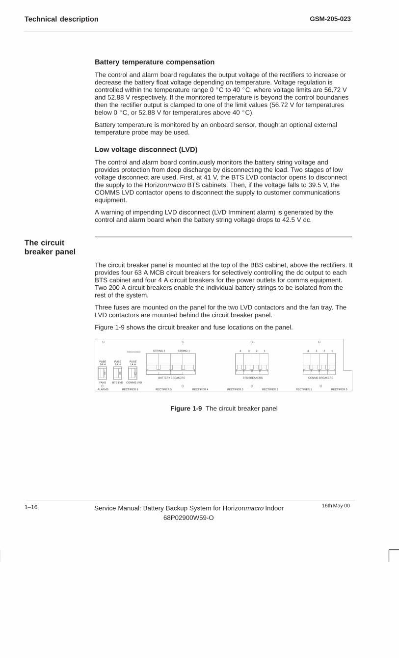
GSM-205-023Technical description
16th May 001–16 Service Manual: Battery Backup System for Horizonmacro Indoor
68P02900W59-O
Battery temperature compensation
The control and alarm board regulates the output voltage of the rectifiers to increase ordecrease the battery float voltage depending on temperature. Voltage regulation iscontrolled within the temperature range 0 �C to 40 �C, where voltage limits are 56.72 Vand 52.88 V respectively. If the monitored temperature is beyond the control boundariesthen the rectifier output is clamped to one of the limit values (56.72 V for temperaturesbelow 0 �C, or 52.88 V for temperatures above 40 �C).
Battery temperature is monitored by an onboard sensor, though an optional externaltemperature probe may be used.
Low voltage disconnect (LVD)
The control and alarm board continuously monitors the battery string voltage andprovides protection from deep discharge by disconnecting the load. Two stages of lowvoltage disconnect are used. First, at 41 V, the BTS LVD contactor opens to disconnectthe supply to the Horizonmacro BTS cabinets. Then, if the voltage falls to 39.5 V, theCOMMS LVD contactor opens to disconnect the supply to customer communicationsequipment.
A warning of impending LVD disconnect (LVD Imminent alarm) is generated by thecontrol and alarm board when the battery string voltage drops to 42.5 V dc.
The circuitbreaker panel
The circuit breaker panel is mounted at the top of the BBS cabinet, above the rectifiers. Itprovides four 63 A MCB circuit breakers for selectively controlling the dc output to eachBTS cabinet and four 4 A circuit breakers for the power outlets for comms equipment.Two 200 A circuit breakers enable the individual battery strings to be isolated from therest of the system.
Three fuses are mounted on the panel for the two LVD contactors and the fan tray. TheLVD contactors are mounted behind the circuit breaker panel.
Figure 1-9 shows the circuit breaker and fuse locations on the panel.
BATTERY BREAKERS BTS BREAKERS COMMS BREAKERS
1234 1234STRING 2 STRING 1
FUSE1A H
FUSE1A H
FUSE5A H
FANS BTS LVD COMMS LVD
ALARMS RECTIFIER 6 RECTIFIER 5 RECTIFIER 4 RECTIFIER 3 RECTIFIER 2 RECTIFIER 1 RECTIFIER 0
Figure 1-9 The circuit breaker panel
GSM-205-023 Technical description
16th May 00 Service Manual: Battery Backup System for Horizonmacro Indoor
68P02900W59-O
1–17
The interfacepanel
The interface panel (see Figure 1-2) is mounted on the top of the BBS cabinet. Inaddition to providing the primary ac supply input to the BBS cabinet, it provides all thepower and alarm connectors required for up to four Horizonmacro indoor cabinets, up tofour customer supplied comms units and additional external battery backup.
Emergency stop facility
An optional external emergency stop button can be connected to the EMERG. STOPconnector on the interface panel. The primary function of this button is to disconnect thebattery power to all connected BTS cabinets in an emergency situation.
The EMERG. STOP connector connects to the N/C contacts of the emergency stopbutton. When the emergency stop button contacts are opened, the BBS opens the BTSand COMMS LVD contactors, thus isolating the –48 V dc battery output.
Opening the BTS and COMMS LVD contactors will only isolate the batterysupply to the BTS and comms equipment. If the ac input to the battery backupsystem is still present then the dc output from the rectifiers will still beproviding a –48 V dc supply to all connected equipment.
The emergency stop button should be a double-pole switch with oneconnection to the BBS to disconnect battery power, and one connection to theac supply to disconnect ac input power to the BBS.
WARNING
The emergency stop connector is fitted with a jumper plug, which MUST be fitted if theemergency stop facility is not used.
Alarm and signal connections
The control and alarm board monitors BBS health and generates alarm signals. Inaddition to alarms connected from the BBS to the master BTS, a single control signal(Battery Test Initiate) may be connected from the master BTS to the BBS.
The BBS interfaces with the master BTS cabinet through the 25-way D-type BTSALARMS connector (cable supplied), which connects to the External Alarms socket onthe master Horizonmacro indoor interface panel. Additional alarms and control signalsare available on the 15-way D-type AUX ALARMS connector (cable not supplied) and, ifrequired, these may be connected to the Horizonmacro indoor cabinet PIX sockets.
For each alarm, two wires are connected to a pair of normally closed (N/C) contactswithin the control and alarm board. Activation of the alarm causes the contacts to open.
Pinout information for the BTS ALARMS connector and the AUX ALARMS connector isshown in Table 1-4 and Table 1-5 respectively.
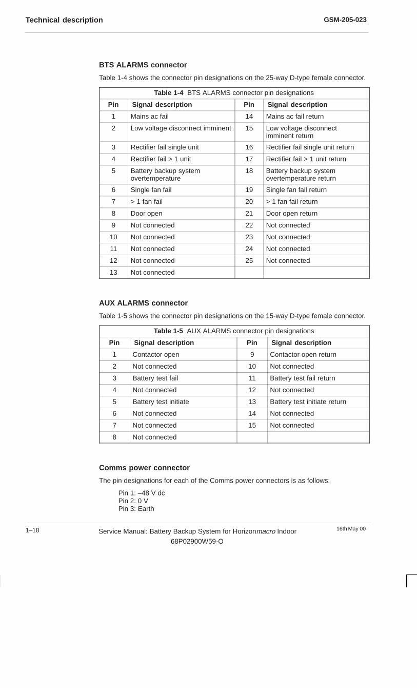
GSM-205-023Technical description
16th May 001–18 Service Manual: Battery Backup System for Horizonmacro Indoor
68P02900W59-O
BTS ALARMS connector
Table 1-4 shows the connector pin designations on the 25-way D-type female connector.
Table 1-4 BTS ALARMS connector pin designations
Pin Signal description Pin Signal description
1 Mains ac fail 14 Mains ac fail return
2 Low voltage disconnect imminent 15 Low voltage disconnectimminent return
3 Rectifier fail single unit 16 Rectifier fail single unit return
4 Rectifier fail > 1 unit 17 Rectifier fail > 1 unit return
5 Battery backup systemovertemperature
18 Battery backup systemovertemperature return
6 Single fan fail 19 Single fan fail return
7 > 1 fan fail 20 > 1 fan fail return
8 Door open 21 Door open return
9 Not connected 22 Not connected
10 Not connected 23 Not connected
11 Not connected 24 Not connected
12 Not connected 25 Not connected
13 Not connected
AUX ALARMS connector
Table 1-5 shows the connector pin designations on the 15-way D-type female connector.
Table 1-5 AUX ALARMS connector pin designations
Pin Signal description Pin Signal description
1 Contactor open 9 Contactor open return
2 Not connected 10 Not connected
3 Battery test fail 11 Battery test fail return
4 Not connected 12 Not connected
5 Battery test initiate 13 Battery test initiate return
6 Not connected 14 Not connected
7 Not connected 15 Not connected
8 Not connected
Comms power connector
The pin designations for each of the Comms power connectors is as follows:
Pin 1: –48 V dcPin 2: 0 VPin 3: Earth
GSM-205-023 BBS specifications
16th May 00 Service Manual: Battery Backup System for Horizonmacro Indoor
68P02900W59-O
1–19
BBS specifications
Overview ofspecifications
This section contains the specifications for the BBS equipment.
Powerspecifications
Input specifications
The Horizonmacro indoor battery backup system operates from either a single phase ora three phase ac supply. Table 1-6 shows the power requirements.
Table 1-6 Input power requirements
Supply voltage range (nominal) Maximum supply current
Single phase120 / 230 V ac (45-66 Hz)
120 A @ 115 V, 50 A @ 230 V
Three phase and neutral (star configuration)208 / 400 V ac (45-66 Hz)
50 A max per phase @ 208 V
22 A max per phase @ 400 V
Output specifications
Maximum output power: 7300 W
(1700 W per BTS x 4 + 125 W per comms unit x 4).
Output voltage(temperature compensated): Nominal: –54 V dc +/– 3%.
Maximum: –59 V dc.
Minimum: –39.5 V dc.
Output current: 135 A at –54 V dc.
185 A at –39.5 V dc.
Rectifier efficiency
>= 82 % at nominal input voltage 110 V ac +/– 10 % and full output load.
Battery temperature compensation
Rectifier output voltage automatically adjusted to provide the batteries with the correctfloat voltage over the entire operating temperature range.
Electromagnetic compatibility
EN50081-1 Light industrial emissions.
EN50082-2 Heavy industrial immunity.

GSM-205-023BBS specifications
16th May 001–20 Service Manual: Battery Backup System for Horizonmacro Indoor
68P02900W59-O
Batteries
Battery specifications
The specifications for the batteries used in the BBS are given in Table 1-7.
Table 1-7 Battery specifications
Internal Type:
Capacity:
Hawker SBS B14 lead-acid (x 8).
65 Ah each.
External Description:
Recommended type:
Nominal voltage:
Maximum current:
Circuit breaker rating:
Cable cross-sectional area:
48 V string (2.27 V / cell @ 20 °Ccharging). Thermal compensation of–3.98 mV / cell per °C.
Hawker SBS B14.
48 V.
180 A @ 41 V.
200 A, 10 000 A breaking capacity.
35 sq. mm minimum.
Battery backup duration
Table 1-8 shows the battery backup capability of the BBS for different equipmentconfigurations.
Where comms equipment is fitted, it is assumed that all four connectors areused, each adding 125 W to the load.
NOTE
Table 1-8 BBS backup times for possible BTS configurations
No. of BTS Cabinets Comms? Y/N Total Load (W) Standby Time (minutes)
String 1 String 1 + 2
1 N 1700 85 170
1 Y 2200 57 115
2 N 3400 36 72
2 Y 3900 30 60
3 N 5100 22 45
3 Y 5600 21 42
4 N 6800 13 27
4 Y 7300 12 24
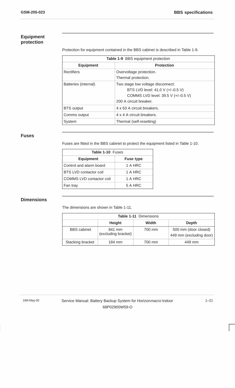
GSM-205-023 BBS specifications
16th May 00 Service Manual: Battery Backup System for Horizonmacro Indoor
68P02900W59-O
1–21
Equipmentprotection
Protection for equipment contained in the BBS cabinet is described in Table 1-9.
Table 1-9 BBS equipment protection
Equipment Protection
Rectifiers Overvoltage protection.
Thermal protection.
Batteries (internal) Two stage low voltage disconnect:
BTS LVD level: 41.0 V (+/–0.5 V)
COMMS LVD level: 39.5 V (+/–0.5 V)
200 A circuit breaker.
BTS output 4 x 63 A circuit breakers.
Comms output 4 x 4 A circuit breakers.
System Thermal (self-resetting)
Fuses
Fuses are fitted in the BBS cabinet to protect the equipment listed in Table 1-10.
Table 1-10 Fuses
Equipment Fuse type
Control and alarm board 1 A HRC
BTS LVD contactor coil 1 A HRC
COMMS LVD contactor coil 1 A HRC
Fan tray 5 A HRC
Dimensions
The dimensions are shown in Table 1-11.
Table 1-11 Dimensions
Height Width Depth
BBS cabinet 841 mm(excluding bracket)
700 mm 500 mm (door closed)
449 mm (excluding door)
Stacking bracket 184 mm 700 mm 449 mm
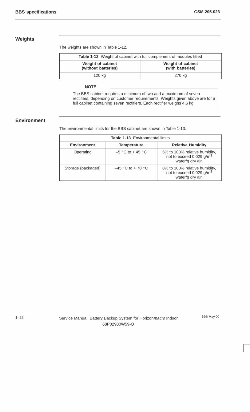
GSM-205-023BBS specifications
16th May 001–22 Service Manual: Battery Backup System for Horizonmacro Indoor
68P02900W59-O
Weights
The weights are shown in Table 1-12.
Table 1-12 Weight of cabinet with full complement of modules fitted
Weight of cabinet(without batteries)
Weight of cabinet(with batteries)
120 kg 270 kg
The BBS cabinet requires a minimum of two and a maximum of sevenrectifiers, depending on customer requirements. Weights given above are for afull cabinet containing seven rectifiers. Each rectifier weighs 4.6 kg.
NOTE
Environment
The environmental limits for the BBS cabinet are shown in Table 1-13.
Table 1-13 Environmental limits
Environment Temperature Relative Humidity
Operating –5 �C to + 45 �C 5% to 100% relative humidity,not to exceed 0.029 g/m3
water/g dry air.
Storage (packaged) –45 �C to + 70 �C 8% to 100% relative humidity,not to exceed 0.029 g/m3
water/g dry air.
16th May 00 Service Manual: Battery Backup System for Horizonmacro Indoor
68P02900W59-O
i
Chapter 2
Installing the battery backup
system

GSM-205-023
16th May 00ii Service Manual: Battery Backup System for Horizonmacro Indoor
68P02900W59-O
GSM-205-023
16th May 00 Service Manual: Battery Backup System for Horizonmacro Indoor
68P02900W59-O
iii
Chapter 2Installing the battery backup system i. . . . . . . . . . . . . . . . . . . . . . . . . . . . . . . . .
Installation overview 2–1. . . . . . . . . . . . . . . . . . . . . . . . . . . . . . . . . . . . . . . . . . . . . . . . . . . . . . . . . Safety precautions 2–1. . . . . . . . . . . . . . . . . . . . . . . . . . . . . . . . . . . . . . . . . . . . . . . . . . . . Installation options 2–1. . . . . . . . . . . . . . . . . . . . . . . . . . . . . . . . . . . . . . . . . . . . . . . . . . . . Tools required 2–1. . . . . . . . . . . . . . . . . . . . . . . . . . . . . . . . . . . . . . . . . . . . . . . . . . . . . . . .
Preparing the site 2–2. . . . . . . . . . . . . . . . . . . . . . . . . . . . . . . . . . . . . . . . . . . . . . . . . . . . . . . . . . . Overview of site preparation 2–2. . . . . . . . . . . . . . . . . . . . . . . . . . . . . . . . . . . . . . . . . . . . BBS specifications and site requirements 2–2. . . . . . . . . . . . . . . . . . . . . . . . . . . . . . . . .
Equipment delivery and unpacking 2–4. . . . . . . . . . . . . . . . . . . . . . . . . . . . . . . . . . . . . . . . . . . . Delivery and unpacking overview 2–4. . . . . . . . . . . . . . . . . . . . . . . . . . . . . . . . . . . . . . . . Unpacking the cabinet 2–5. . . . . . . . . . . . . . . . . . . . . . . . . . . . . . . . . . . . . . . . . . . . . . . . .
Installing the BBS cabinet 2–6. . . . . . . . . . . . . . . . . . . . . . . . . . . . . . . . . . . . . . . . . . . . . . . . . . . . Overview of BBS installation 2–6. . . . . . . . . . . . . . . . . . . . . . . . . . . . . . . . . . . . . . . . . . . . Preparing the BBS cabinet for installation 2–7. . . . . . . . . . . . . . . . . . . . . . . . . . . . . . . . . BBS cabinet installation options 2–8. . . . . . . . . . . . . . . . . . . . . . . . . . . . . . . . . . . . . . . . .
Cable connections to the BBS cabinet 2–10. . . . . . . . . . . . . . . . . . . . . . . . . . . . . . . . . . . . . . . . . Overview of cable connections 2–10. . . . . . . . . . . . . . . . . . . . . . . . . . . . . . . . . . . . . . . . . . Connecting dc output power cables 2–11. . . . . . . . . . . . . . . . . . . . . . . . . . . . . . . . . . . . . . Comms power output cable connections 2–11. . . . . . . . . . . . . . . . . . . . . . . . . . . . . . . . . Alarm and signal cable connections 2–12. . . . . . . . . . . . . . . . . . . . . . . . . . . . . . . . . . . . . . Connecting the emergency stop cable 2–13. . . . . . . . . . . . . . . . . . . . . . . . . . . . . . . . . . . Earthing the BBS cabinet 2–13. . . . . . . . . . . . . . . . . . . . . . . . . . . . . . . . . . . . . . . . . . . . . . . Connecting single phase ac input cables 2–14. . . . . . . . . . . . . . . . . . . . . . . . . . . . . . . . . Connecting three phase ac input cables 2–15. . . . . . . . . . . . . . . . . . . . . . . . . . . . . . . . . .
Installing the internal batteries 2–16. . . . . . . . . . . . . . . . . . . . . . . . . . . . . . . . . . . . . . . . . . . . . . . . Introduction to internal battery installation 2–16. . . . . . . . . . . . . . . . . . . . . . . . . . . . . . . . . Setting the battery string dipswitch 2–17. . . . . . . . . . . . . . . . . . . . . . . . . . . . . . . . . . . . . . Battery installation safety precautions 2–18. . . . . . . . . . . . . . . . . . . . . . . . . . . . . . . . . . . . Procedure for installing the internal batteries 2–19. . . . . . . . . . . . . . . . . . . . . . . . . . . . . .
Connecting external battery strings 2–22. . . . . . . . . . . . . . . . . . . . . . . . . . . . . . . . . . . . . . . . . . . . Introduction to external battery strings 2–22. . . . . . . . . . . . . . . . . . . . . . . . . . . . . . . . . . . Safety precautions for connecting external batteries 2–22. . . . . . . . . . . . . . . . . . . . . . . Connecting an external battery string 2–22. . . . . . . . . . . . . . . . . . . . . . . . . . . . . . . . . . . .
Installing the rectifiers 2–23. . . . . . . . . . . . . . . . . . . . . . . . . . . . . . . . . . . . . . . . . . . . . . . . . . . . . . . Introduction to rectifier installation 2–23. . . . . . . . . . . . . . . . . . . . . . . . . . . . . . . . . . . . . . . Rectifier installation procedure 2–24. . . . . . . . . . . . . . . . . . . . . . . . . . . . . . . . . . . . . . . . . .
Stacking an Horizonmacro indoor cabinet on the BBS cabinet 2–26. . . . . . . . . . . . . . . . . . . . Fitting the stacking bracket onto the BBS 2–26. . . . . . . . . . . . . . . . . . . . . . . . . . . . . . . . . Fitting an Horizonmacro indoor cabinet onto the stacking bracket 2–27. . . . . . . . . . . .
Commissioning the BBS cabinet 2–28. . . . . . . . . . . . . . . . . . . . . . . . . . . . . . . . . . . . . . . . . . . . . . Pre-power up checks 2–28. . . . . . . . . . . . . . . . . . . . . . . . . . . . . . . . . . . . . . . . . . . . . . . . . . Powering up the BBS cabinet 2–28. . . . . . . . . . . . . . . . . . . . . . . . . . . . . . . . . . . . . . . . . . . Powering down the BBS cabinet 2–29. . . . . . . . . . . . . . . . . . . . . . . . . . . . . . . . . . . . . . . .
Decommissioning the BBS cabinet 2–30. . . . . . . . . . . . . . . . . . . . . . . . . . . . . . . . . . . . . . . . . . . . Before starting to decommission the BBS cabinet 2–30. . . . . . . . . . . . . . . . . . . . . . . . . Procedure to remove a stacked Horizonmacro indoor cabinet 2–30. . . . . . . . . . . . . . . Procedure to decommission the BBS cabinet 2–31. . . . . . . . . . . . . . . . . . . . . . . . . . . . .

GSM-205-023
16th May 00iv Service Manual: Battery Backup System for Horizonmacro Indoor
68P02900W59-O
GSM-205-023 Installation overview
16th May 00 Service Manual: Battery Backup System for Horizonmacro Indoor
68P02900W59-O
2–1
Installation overview
Safetyprecautions
Observe all relevant safety precautions. In particular, the following safety precautionsmust be observed when installing the equipment described in this supplement:
This equipment must only be installed by trained personnel.
WARNING
� Installation and commissioning must comply with all relevant national and regionalregulations.
� The equipment must only be installed in a location which has controlled access.
� The BBS cabinet must be bolted to the floor (unless it is to be mounted on top ofan M-Cell6 battery box).
� Insulated tools must be used to connect battery terminals.
Installationoptions
The following installation options are available for the BBS:
� Stand-alone, next to an Horizonmacro indoor cabinet.
� Beneath an Horizonmacro indoor cabinet.
� On top of a single M-Cell6 battery box.
Once installed, the BBS provides primary dc power (–48 V) for up to four Horizonmacroindoor cabinets, and also provides battery backup to maintain power to the four cabinetsfor more than 20 minutes in the event of loss of primary ac power.
If the battery backup system is to be installed as an addition to an in-service –48 VHorizonmacro indoor installation, then it will be necessary to power down the in-serviceequipment prior to connecting the BBS. Also, if the BBS is to be fitted beneath anin-service Horizonmacro indoor cabinet then a special BBS stacking bracket must befitted on top of the BBS cabinet.
For details of Horizonmacro indoor cabinet power down and removal procedures refer toInstallation and Configuration: Horizonmacro Indoor (GSM-205-423).
This chapter describes the procedures required to install a BBS in a stackableconfiguration beneath an Horizonmacro indoor cabinet. Installation of a BBS next to anHorizonmacro indoor cabinet is essentially the same, but without the need for theadditional stacking bracket.
The procedure for installing the BBS on top of an M-Cell6 battery box is also describedseparately in this chapter.
Tools required
The recommended tools required to install a BBS are listed in Installation andConfiguration: Horizonmacro Indoor (GSM-205-423).

GSM-205-023Preparing the site
16th May 002–2 Service Manual: Battery Backup System for Horizonmacro Indoor
68P02900W59-O
Preparing the site
Overview of sitepreparation
The battery backup system is primarily intended for use with the Horizonmacro indoorBTS cabinet. The site requirements and considerations applicable to the Horizonmacroindoor are equally applicable to the BBS. Refer to Installation and Configuration:Horizonmacro Indoor (GSM-205-423) Introduction and site preparation for sitepreparation details.
BBSspecificationsand siterequirements
The BBS cabinet dimensions, weights and environmental limits are described in Chapter1, BBS specifications .
The BBS cabinet, with all modules fitted, weighs 120 kg without batteries and270 kg with all eight batteries installed. For safety reasons, the batteries areshipped separately from the BBS cabinet. Observe the correct liftingprecautions when handling the cabinet and do not attempt to lift the cabinetwith the batteries installed.
WARNING
The BBS is intended to be installed with an Horizonmacro indoor cabinetmounted above it on a stacking bracket. The combined weight of the stackedcabinets is 400 kg. Ensure the floor is capable of supporting this weight.
CAUTION
If an Horizonmacro indoor cabinet is to be fitted above the BBS, then adequate heightclearance must be allowed for both cabinets and the stacking bracket (a total of1900 mm when a hood fitted on top of the Horizonmacro indoor).
Adequate clearance must be provided at the front of the equipment for operation andmaintenance purposes. There must be adequate side clearance (50 mm) to enable thedoor to open at 95° and, for easy access to batteries and modules, this may beincreased to 500 mm to allow the door to open to 130°.
If an Horizonmacro indoor cabinet is to be installed on top of the BBS, thenside clearances required for indoor cabinet ventilation must also beconsidered.
NOTE
Ventilating air is drawn in through the grille at the bottom of the BBS cabinet front, andthrough the grille on the front of the door. Air is expelled through the interface panelventilated area on the top of the cabinet. When a stacking bracket is fitted, expelled airexits through the stacking bracket front grille, and through the area to the rear of thestacking bracket.
Take care to ensure air flow is not restricted.
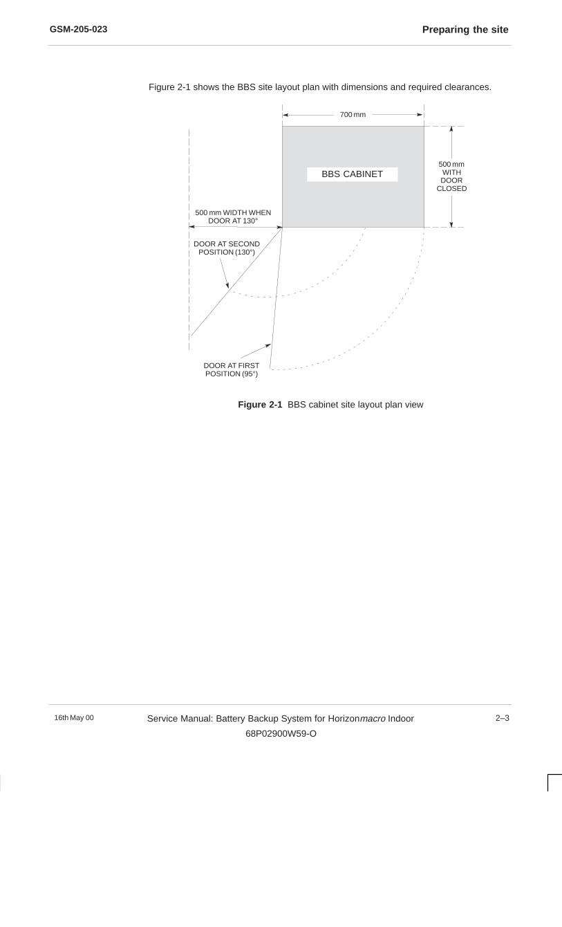
GSM-205-023 Preparing the site
16th May 00 Service Manual: Battery Backup System for Horizonmacro Indoor
68P02900W59-O
2–3
Figure 2-1 shows the BBS site layout plan with dimensions and required clearances.
700 mm
DOOR AT SECONDPOSITION (130°)
DOOR AT FIRSTPOSITION (95°)
500 mm WIDTH WHENDOOR AT 130°
BBS CABINET500 mmWITHDOOR
CLOSED
Figure 2-1 BBS cabinet site layout plan view

GSM-205-023Equipment delivery and unpacking
16th May 002–4 Service Manual: Battery Backup System for Horizonmacro Indoor
68P02900W59-O
Equipment delivery and unpacking
Delivery andunpackingoverview
Package delivery
Before the cabinet equipment arrives, installation personnel should designate an area atthe site where the equipment can be unloaded. This area should also be suitable forunpacking the equipment. Consult with the heavy freight or moving company and theowners of the building (if applicable) to select this area.
The cabinet equipment should be delivered to the site while still contained in itspackaging. This is to protect the cabinet in transit and from moisture.
CAUTION
The equipment should be carefully delivered to the site by the freight company, alongwith the necessary moving dollies and padding. Use the dollies and padding to move theequipment from the unloading area to the installation point.
Keep all paperwork attached to the packaging, or found inside the cabinet.The keys for the cabinet are taped to the inside of the door.
NOTE
Package contents
Most equipment modules are supplied already fitted in the cabinet. The exceptions to thisare:
� The rectifiers.
The number of rectifiers supplied depends on customer requirements, anddetermines how many blanking panels are fitted in the rectifier rack. For example,if three rectifiers are ordered, four blanking panels will already be fitted in slots 3 to6.
� The 12 V monoblocs.
The 12 V monoblocs are packaged and delivered separately for safety reasons.
The number of monoblocs supplied (0, 4 or 8) depends on customer requirements.
� Power cables.
DC power cables for the BTS and comms power cables are ordered and packagedseparately.
� Sundry items.
These include battery cables, link bars, alarm cable, mounting washers, etc. Theseare packed loose in the BBS battery compartment.
� Stacking bracket.
If a stacking bracket is required, this is packed separately, together with its frontpanel and fixing screws.
The cabinet is packed in a cardboard container, secured to a wooden delivery base.

GSM-205-023 Equipment delivery and unpacking
16th May 00 Service Manual: Battery Backup System for Horizonmacro Indoor
68P02900W59-O
2–5
Unpacking thecabinet
The BBS cabinet weighs approximately 88 kg before the rectifiers andmonoblocs are installed. Handle each cabinet with extreme care and inaccordance with local health and safety regulations.
WARNING
To remove the cabinet from the wooden base:
Take care to avoid damaging the cabinet in any way, especially by scratchingthe outer surfaces.
CAUTION
1. Inspect the packaging for visible signs of damage.
2. Cut and remove the three bands from around the packaging.
3. Remove the lid, the four cardboard corner posts, and then lift off the outercardboard sleeve.
4. Carefully cut around the base of the sealed foil bag containing the cabinet. Lift thebag and top corrugated fitting off the cabinet.
5. Remove the cabinet from the pallet.
6. Remove the desiccant bag from the cabinet.
7. Inspect the equipment immediately for damage (both inside and outside). Reportthe extent of any damage to the transport company.
The cabinet unpacking procedure is now complete.
The packing material used by Motorola is non-returnable and should bedisposed of safely.
NOTE


GSM-205-023Installing the BBS cabinet
16th May 002–6 Service Manual: Battery Backup System for Horizonmacro Indoor
68P02900W59-O
Installing the BBS cabinet
Overview of BBSinstallation
This equipment must only be installed by trained personnel.
WARNING
Installing the BBS on the floor
The BBS may be installed next to or beneath an Horizonmacro indoor BTS cabinet. Aspecial stacking bracket must be used when an indoor cabinet is to be stacked on top ofthe BBS cabinet.
Regardless of whether or not an indoor cabinet is to be mounted on top of theBBS cabinet, the method of securing the BBS to the floor is the same.
NOTE
Installation comprises the following steps:
� Securing the BBS cabinet in position.
� Connecting cables to the BBS interface panel.
� Connecting external batteries (if required).
� If an Horizonmacro indoor cabinet is to be mounted on top of the BBS cabinet:
– Fitting the stacking bracket.
– Lifting the Horizonmacro indoor cabinet onto the stacking bracket andsecuring in position.
� Connecting cables to the Horizonmacro indoor cabinet(s).
� Installing the internal batteries.
� Installing the rectifiers.
� Connecting input power.
Installing the BBS on top of an M-Cell 6 indoor battery box
The BBS may be installed on top of a single M-Cell6 battery box. A stacking bracket isnot required for this application.
Installation comprises the following steps:
� Installing the M-Cell6 battery box (assumed to have been previously installed).
� Lifting the BBS cabinet onto the M-Cell6 battery box and securing in position.
� Connecting cables to the BBS interface panel (same procedure as for use withHorizonmacro indoor cabinets).
� If required, connecting external batteries (same procedure as for use withHorizonmacro indoor cabinets).
� Installing the internal batteries (same procedure as for use with Horizonmacroindoor cabinets).
� Installing the rectifiers (same procedure as for use with Horizonmacro indoorcabinets).
� Connecting input power (same procedure as for use with Horizonmacro indoorcabinets).
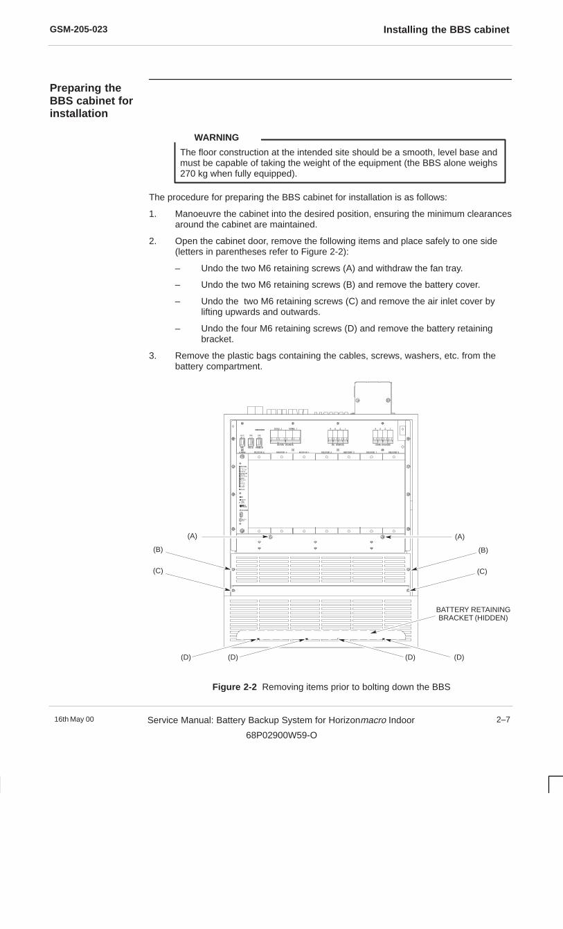
GSM-205-023 Installing the BBS cabinet
16th May 00 Service Manual: Battery Backup System for Horizonmacro Indoor
68P02900W59-O
2–7
Preparing theBBS cabinet forinstallation
The floor construction at the intended site should be a smooth, level base andmust be capable of taking the weight of the equipment (the BBS alone weighs270 kg when fully equipped).
WARNING
The procedure for preparing the BBS cabinet for installation is as follows:
1. Manoeuvre the cabinet into the desired position, ensuring the minimum clearancesaround the cabinet are maintained.
2. Open the cabinet door, remove the following items and place safely to one side(letters in parentheses refer to Figure 2-2):
– Undo the two M6 retaining screws (A) and withdraw the fan tray.
– Undo the two M6 retaining screws (B) and remove the battery cover.
– Undo the two M6 retaining screws (C) and remove the air inlet cover bylifting upwards and outwards.
– Undo the four M6 retaining screws (D) and remove the battery retainingbracket.
3. Remove the plastic bags containing the cables, screws, washers, etc. from thebattery compartment.
(A)(A)
(B)(B)
(C)(C)
BATTERY RETAININGBRACKET (HIDDEN)
(D)(D) (D)(D)
Figure 2-2 Removing items prior to bolting down the BBS
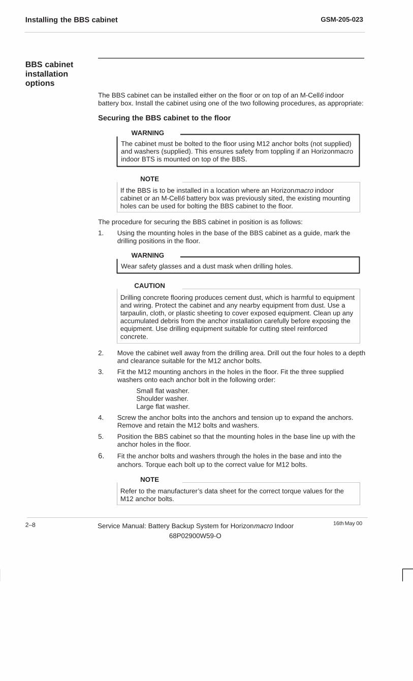
GSM-205-023Installing the BBS cabinet
16th May 002–8 Service Manual: Battery Backup System for Horizonmacro Indoor
68P02900W59-O
BBS cabinetinstallationoptions
The BBS cabinet can be installed either on the floor or on top of an M-Cell6 indoorbattery box. Install the cabinet using one of the two following procedures, as appropriate:
Securing the BBS cabinet to the floor
The cabinet must be bolted to the floor using M12 anchor bolts (not supplied)and washers (supplied). This ensures safety from toppling if an Horizonmacroindoor BTS is mounted on top of the BBS.
WARNING
If the BBS is to be installed in a location where an Horizonmacro indoorcabinet or an M-Cell6 battery box was previously sited, the existing mountingholes can be used for bolting the BBS cabinet to the floor.
NOTE
The procedure for securing the BBS cabinet in position is as follows:
1. Using the mounting holes in the base of the BBS cabinet as a guide, mark thedrilling positions in the floor.
Wear safety glasses and a dust mask when drilling holes.
WARNING
Drilling concrete flooring produces cement dust, which is harmful to equipmentand wiring. Protect the cabinet and any nearby equipment from dust. Use atarpaulin, cloth, or plastic sheeting to cover exposed equipment. Clean up anyaccumulated debris from the anchor installation carefully before exposing theequipment. Use drilling equipment suitable for cutting steel reinforcedconcrete.
CAUTION
2. Move the cabinet well away from the drilling area. Drill out the four holes to a depthand clearance suitable for the M12 anchor bolts.
3. Fit the M12 mounting anchors in the holes in the floor. Fit the three suppliedwashers onto each anchor bolt in the following order:
Small flat washer.Shoulder washer.Large flat washer.
4. Screw the anchor bolts into the anchors and tension up to expand the anchors.Remove and retain the M12 bolts and washers.
5. Position the BBS cabinet so that the mounting holes in the base line up with theanchor holes in the floor.
6. Fit the anchor bolts and washers through the holes in the base and into theanchors. Torque each bolt up to the correct value for M12 bolts.
Refer to the manufacturer’s data sheet for the correct torque values for theM12 anchor bolts.
NOTE

GSM-205-023 Installing the BBS cabinet
16th May 00 Service Manual: Battery Backup System for Horizonmacro Indoor
68P02900W59-O
2–9
Securing the BBS cabinet on an M-Cell 6 indoor battery box
Although the BBS cabinet can be mounted on top of a single M-Cell6 batterybox, the BBS itself is not designed for use with the M-Cell6 equipment.
NOTE
The floor must be capable of taking the combined weight of the M-Cell6battery box and the BBS cabinet.
WARNING
The BBS cabinet can be mounted directly onto the top of an M-Cell6 battery box. Astacking bracket is not required for this application.
The procedure for mounting the BBS cabinet on top of a previously installed M-Cell6battery box is as follows:
1. Remove the four plugs in the top of the battery box to expose the fixing holes.Store the plugs for future use.
2. Remove the four M8 hex head bolts from the four lifting holes in the top panel ofthe BBS cabinet (the holes are identified by the word LIFT next to them). ScrewM8 eyebolts into the four lifting holes.
3. Lift the BBS cabinet onto the battery box, taking care to ensure that the holes onthe base are aligned with the exposed threaded holes in the top of the battery box.
4. Fit the three supplied washers onto the M12 bolts (supplied with the M-Cell6),insert the bolts through the holes in the base of the BBS cabinet and into thethreaded holes on the battery box. Tighten the bolts to 40 Nm.

GSM-205-023Cable connections to the BBS cabinet
16th May 002–10 Service Manual: Battery Backup System for Horizonmacro Indoor
68P02900W59-O
Cable connections to the BBS cabinet
Overview ofcableconnections
All fixed installation wiring, earthing and protective devices must comply withthe applicable national and regional wiring regulations.
WARNING
The BBS provides –48 V dc power for up to four Horizonmacro indoor cabinets. Fouradditional –48 V dc outputs are provided for customer communications equipment.Alarms and signals from the BBS cabinet are routed to the EXTERNAL ALARMS andPIX connectors on the indoor cabinet designated as the master.
Primary ac power for the BBS is provided from either a single phase supply or from athree phase supply.
The battery backup time provided by the BBS in the event of a failure of the ac supplymay be extended by wiring in optional external battery strings.
An optional emergency stop button may be connected to the BBS. This will disconnectthe –48 V battery power in an emergency. The emergency stop connection only providesa battery disconnect facility, it does not disconnect the primary ac power source.
All external cable connections are made from the interface panel on the top of the BBScabinet. Figure 2-3 shows the positions of the connectors on the interface panel.
If an indoor cabinet is to be stacked on top of the BBS cabinet, connect thecables to the BBS interface panel, but do not make the connections to theindoor cabinet until after the cabinet has been stacked (see Stacking anHorizon macro indoor cabinet on the BBS cabinet later in this chapter).
NOTE
EXTERNAL BATTERYCONNECTORS
BTS ALARMSCONNECTOR
AUX ALARMSCONNECTOR
AC SUPPLYCONNECTORCOMMS POWER
CONNECTORS
EMERGENCY STOPCONNECTOR
EARTHSTUD
BTS DC SUPPLYCONNECTORS
EXTERNAL BATTERYBTS POWER
BTS AUXALARMS COMMS POWER
EMERG.STOP
AC INPUT POWER
Figure 2-3 Connectors on the BBS interface panel
GSM-205-023 Cable connections to the BBS cabinet
16th May 00 Service Manual: Battery Backup System for Horizonmacro Indoor
68P02900W59-O
2–11
Connecting dcoutput powercables
Four pairs of Anderson connectors are mounted on the BBS interface panel, enabling upto four Horizonmacro indoor cabinets to be connected to the BBS. The four pairs arelabelled BTS POWER 1, 2, 3 and 4, and each individual pair comprises a black 0 Vconnector and a blue –48 V connector.
When connecting dc power to the Horizonmacro indoor cabinets, observe the followingrules:
� The negative (–48 V dc ) power cable is blue .
� The positive (0 V) power cable is black .
The procedure for connecting each dc output power cable is as follows:
1. Route and secure a blue/black power cable pair from the BBS to the Horizonmacroindoor cabinet, ensuring adequate allowance is made to connect each end withoutcausing undue strain on the cable.
2. At the BBS, identify the BTS POWER connector pair to be used (1, 2, 3 or 4),then:
Connect the black cable to the black Anderson connector.
Connect the blue cable to the blue Anderson connector.
3. Refer to Installation and Configuration: Horizonmacro Indoor (GSM-205-423)Installing and connecting power and earth cabling for details of connecting dcpower (positive earth) to the Horizonmacro indoor cabinet.
Comms poweroutput cableconnections
The BBS provides four –48 V dc outputs to supply customer communications equipment.Connections for these outputs are mounted on the BBS interface panel in the form offour 3-way mate-n-lock sockets.
Pinout details are as follows:
Pin 1: –48 V dc (blue cable).
Pin 2: 0 V (black cable).
Pin 3: Earth (green/yellow cable).

GSM-205-023Cable connections to the BBS cabinet
16th May 002–12 Service Manual: Battery Backup System for Horizonmacro Indoor
68P02900W59-O
Alarm and signalcableconnections
Alarm and signal connections to the Horizonmacro indoor master cabinet are made usingthe supplied 25-way to 37-way cable. The 25-way D-type plug connects to the socketmarked BTS ALARMS on the BBS interface panel. The 37-way D-type plug connects tothe socket marked EXTERNAL ALARMS on the indoor cabinet.
The EXTERNAL ALARMS connector on the master Horizonmacro indoorcabinet interface panel is fitted with a shorting plug which must be removed toallow connection of the alarm cable from the BBS.
NOTE
The connections between the BTS ALARMS connector on the BBS interface panel andthe EXTERNAL ALARMS connector on the master Horizonmacro indoor cabinet areshown in Table 2-1.
Table 2-1 BBS to BTS alarm signal connections
BBS interface panel
BTS ALARMS connector
Master Horizonmacro indoor cabinetinterface panel
EXTERNAL ALARMS connector
Pin Signal/Description Pin Signal/Description
1 Mains ac fail 1 Mains ac 1 fail
2 Low voltage disconnect imminent 15 Low voltage disconnect alarm
3 Rectifier fail single unit 19 Rectifier 1 fail
4 Rectifier fail > 1 unit 21 Rectifier 2 fail
5 BBS overtemperature 29 ANC CAB Overtemp alarm
6 Single fan fail 5 HMS 1 failure
7 > 1 fan fail 7 HMS 2 failure
8 Door open 25 Door 2 open
9-13 Not connected
14 Mains ac fail return 2 Mains ac 1 fail return
15 Low voltage disconnect imminentreturn
16 Low voltage disconnect return
16 Rectifier fail single unit return 20 Rectifier 1 return
17 Rectifier fail > 1 unit return 22 Rectifier 2 return
18 BBS overtemperature return 30 ANC CAB Overtemp return
19 Single fan fail return 6 HMS 1 return
20 > 1 fan fail return 8 HMS 2 return
21 Door open return 26 Door 2 return
22-25 Not connected
Additional alarm and signal connectivity is provided by the 15-way AUX ALARMS socketwhich may be connected by customers to the PIX alarms connector on the indoorcabinet. See The interface panel in Chapter 1 for alarm and signal details.
GSM-205-023 Cable connections to the BBS cabinet
16th May 00 Service Manual: Battery Backup System for Horizonmacro Indoor
68P02900W59-O
2–13
Connecting theemergency stopcable
A two-way mate-n-lock socket, labelled EMERG. STOP, is provided on the BBS interfacepanel for connection to a remote emergency stop button. When a button is fitted and thecontacts are opened, the BBS causes the BTS and COMMS LVD contactors to open, sodisconnecting battery power to the Horizonmacro indoor cabinet(s) and the customercommunications equipment.
Simply connecting an emergency stop button to the connectors on theEMERG. STOP socket does not disconnect the ac power supply to the BBS,and does not disable the dc output from the rectifiers. The ac power supplymust also be disconnected to completely isolate the BBS.This can be achieved by using a double pole emergency stop switch, with onepair of contacts connected to the BBS interface panel to isolate the batteries,and the second pair of contacts connected externally to isolate the ac powersupply to the BBS.
WARNING
If the emergency stop facility is not used, then the jumper plug (a two-waymate-n-lock plug with pins linked together) must be fitted to the EMERG.STOP socket. The BBS will power up, but the batteries will bedisconnected from the system if the jumper plug is not fitted.
NOTE
Earthing the BBScabinet
BBS cabinet earthing is provided by the earth cable from the ac power source, and by asupplementary earth connection to a 10 mm M6 threaded stud located on the BBSinterface panel (see Figure 2-3). It is important to make both earth connections. SeeConnecting single phase ac input cables or Connecting three phase ac inputcables for connecting the earth cable from an ac power source.
The BBS cabinet must be earthed separately, and must not be daisy chainedto another cabinet.
WARNING
The procedure to fit the supplementary earth connection is as follows:
1. Locate a suitable earth point (refer to Grounding guidelines for cellular radioinstallations: 68P81150E62 for detailed earthing information).
2. Connect an earth wire from the earth point to the earth stud on the BBS interfacepanel. Tighten to a torque of 3.4 Nm.
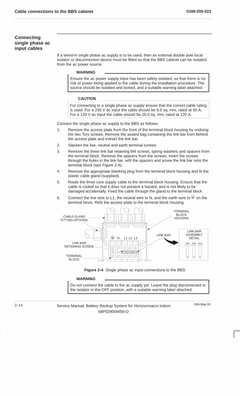
GSM-205-023Cable connections to the BBS cabinet
16th May 002–14 Service Manual: Battery Backup System for Horizonmacro Indoor
68P02900W59-O
Connectingsingle phase acinput cables
If a wired-in single phase ac supply is to be used, then an external double pole localisolator or disconnection device must be fitted so that the BBS cabinet can be isolatedfrom the ac power source.
Ensure the ac power supply input has been safely isolated, so that there is norisk of power being applied to the cable during the installation procedure. Thesource should be isolated and locked, and a suitable warning label attached.
WARNING
For connecting to a single phase ac supply ensure that the correct cable ratingis used. For a 230 V ac input the cable should be 6.0 sq. mm, rated at 50 A.For a 120 V ac input the cable should be 25.0 sq. mm, rated at 120 A.
CAUTION
Connect the single phase ac supply to the BBS as follows:
1. Remove the access plate from the front of the terminal block housing by undoingthe two Torx screws. Remove the sealed bag containing the link bar from behindthe access plate and extract the link bar.
2. Slacken the live, neutral and earth terminal screws.
3. Remove the three link bar retaining M4 screws, spring washers and spacers fromthe terminal block. Remove the spacers from the screws, insert the screwsthrough the holes in the link bar, refit the spacers and screw the link bar onto theterminal block (see Figure 2-4).
4. Remove the appropriate blanking plug from the terminal block housing and fit theplastic cable gland (supplied).
5. Route the three core supply cable to the terminal block housing. Ensure that thecable is routed so that it does not present a hazard, and is not likely to bedamaged accidentally. Feed the cable through the gland to the terminal block.
6. Connect the live wire to L1, the neutral wire to N, and the earth wire to on theterminal block. Refit the access plate to the terminal block housing.
L1 L2 L3NLINK BAR
TERMINALBLOCK
HOUSING
TERMINALBLOCK
LINK BARRETAINING SCREW
CABLE GLANDFITTING OPTIONS
LINK BARASSEMBLY
DETAIL
Figure 2-4 Single phase ac input connections to the BBS
Do not connect the cable to the ac supply yet. Leave the plug disconnected orthe isolator in the OFF position, with a suitable warning label attached.
WARNING

GSM-205-023 Cable connections to the BBS cabinet
16th May 00 Service Manual: Battery Backup System for Horizonmacro Indoor
68P02900W59-O
2–15
Connecting threephase ac inputcables
If a wired-in three phase ac connection is required, then an external four pole isolator ordisconnection device must be used.
Ensure the ac power supply input has been safely isolated, so that there is norisk of power being applied to the cable during the installation procedure. Thesource should be isolated and locked, and a suitable warning label attached.
WARNING
For connecting to a three phase ac supply ensure that the correct cable ratingis used. For a 400 V ac three phase input, the cable should be 2.5 sq. mm,rated at 22 A. For a 208 V ac three phase input, the cable should be6.0 sq. mm, rated at 50 A.
CAUTION
Connect the three phase ac supply to the BBS in a star configuration as follows (seeFigure 2-5):
1. Remove the access plate from the front of the terminal block housing by undoingthe two Torx screws. Remove the sealed bag containing the link bar from behindthe access plate and store for possible future use.
2. Slacken the live, neutral and earth terminal screws.
3. Remove the appropriate blanking plug from the terminal block housing and fit theplastic cable gland (supplied).
4. Carefully route the five core supply cable to the terminal block housing so that itdoes not present a hazard, and is unlikely to be damaged accidentally. Feed thecable through the gland to the ac input terminal block.
5. Connect the phase 1 wire to L1, the phase 2 wire to L2, the phase 3 wire to L3, theneutral wire to N, and the earth wire to on the terminal block. Refit the accessplate to the terminal block housing.
L1 L2 L3N
CABLE GLANDFITTING OPTIONS
TERMINALBLOCK
HOUSING
TERMINALBLOCK
Figure 2-5 Three phase ac input connections to the BBS
Do not connect the cable to the ac supply yet. Leave the plug disconnected orthe isolator in the OFF position, with a suitable warning label attached.
WARNING
GSM-205-023Installing the internal batteries
16th May 002–16 Service Manual: Battery Backup System for Horizonmacro Indoor
68P02900W59-O
Installing the internal batteries
Introduction tointernal batteryinstallation
For safety reasons, the internal batteries are supplied separately from the BBS cabinet.The monoblocs should be installed and connected as soon possible after the cabinet issecured in its permanent location.
The eight monoblocs are arranged in two internal battery strings. Each string containsfour 12 V monoblocs, connected in series to produce a –48 V dc output. The BBS isprimarily designed for use with all eight monoblocs fitted, but will operate at reducedcapacity with just four monoblocs (one string).
One or two external battery strings can be connected to the BBS to increase the batterybackup time.
The BBS can also operate with no batteries installed. In this case the BBSsimply operates as a –48 V dc supply for up to four Horizonmacro indoorcabinets.
NOTE
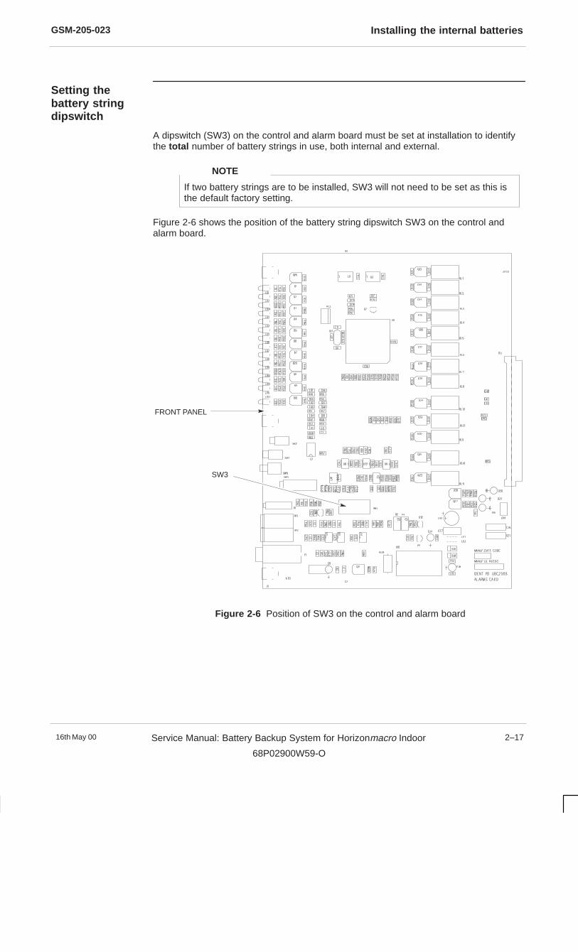
GSM-205-023 Installing the internal batteries
16th May 00 Service Manual: Battery Backup System for Horizonmacro Indoor
68P02900W59-O
2–17
Setting thebattery stringdipswitch
A dipswitch (SW3) on the control and alarm board must be set at installation to identifythe total number of battery strings in use, both internal and external.
If two battery strings are to be installed, SW3 will not need to be set as this isthe default factory setting.
NOTE
Figure 2-6 shows the position of the battery string dipswitch SW3 on the control andalarm board.
SW3
FRONT PANEL
Figure 2-6 Position of SW3 on the control and alarm board
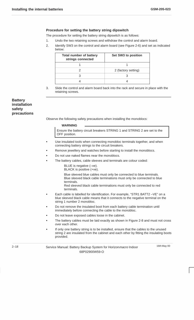
GSM-205-023Installing the internal batteries
16th May 002–18 Service Manual: Battery Backup System for Horizonmacro Indoor
68P02900W59-O
Procedure for setting the battery string dipswitchThe procedure for setting the battery string dipswitch is as follows:
1. Undo the two retaining screws and withdraw the control and alarm board.
2. Identify SW3 on the control and alarm board (see Figure 2-6) and set as indicatedbelow:
Total number of batterystrings connected
Set SW3 to position
1 1
2 2 (factory setting)
3 3
4 4
3. Slide the control and alarm board back into the rack and secure in place with theretaining screws.
Batteryinstallationsafetyprecautions
Observe the following safety precautions when installing the monoblocs:
Ensure the battery circuit breakers STRING 1 and STRING 2 are set to theOFF position.
WARNING
� Use insulated tools when connecting monobloc terminals together, and whenconnecting battery strings to the circuit breakers.
� Remove jewellery and watches before starting to install the monoblocs.
� Do not use naked flames near the monoblocs.
� The battery cables, cable sleeves and terminals are colour coded:
BLUE is negative (–ve).BLACK is positive (+ve).
Blue sleeved blue cables must only be connected to blue terminals.Blue sleeved black cable terminations must only be connected to blueterminals.Red sleeved black cable terminations must only be connected to redterminals.
� Each cable is labelled for identification. For example, “STR1 BATT2 –VE” on ablue sleeved black cable means that it connects to the negative terminal on thestring 1 number 2 monobloc.
� Do not remove the insulated boot from each battery cable termination untilimmediately before connecting the cable to the monobloc.
� Do not leave exposed cables loose in the cabinet.
� The battery cables must be laid exactly as shown in Figure 2-8 and must not crossover each other.
� If only one battery string is to be installed, ensure that the cables to the unusedstring 2 are insulated from the cabinet and each other by fitting the insulating bootsprovided.

GSM-205-023 Installing the internal batteries
16th May 00 Service Manual: Battery Backup System for Horizonmacro Indoor
68P02900W59-O
2–19
Procedure forinstalling theinternal batteries
The BBS cabinet is already prepared for the monoblocs to be installed (see Preparingthe BBS cabinet for installation earlier in this chapter).
Remove the monoblocs, terminal bolts and spring washers from their packaging. Smeara small amount of light grease onto the bolt threads prior to fitting. Refer to Figure 2-7and Figure 2-8 and proceed as follows to install the monoblocs in the BBS cabinet:
Observe the safety precautions given in the previous section. There is adanger of explosion if the monoblocs are installed incorrectly.
WARNING
Installing a single battery string1. Slide monobloc 1–1 into position. Fit the bolt and spring washer to the red sleeved
(+) termination of the black cable marked “STR1 BATT1 +VE” and connect it to thered (+) terminal on the monobloc. Tighten the bolt to 5 Nm and fit the nut cap.
Fit the bolt and spring washer to the blue sleeved (–) termination of the blue cablemarked “STR1 BATT1 –VE” and connect it to the blue (–) terminal on themonobloc. Tighten the bolt to 5 Nm and fit the nut cap.
2. Slide monobloc 1–2 into position and connect the blue sleeved (–) termination ofthe black cable marked “STR1 BATT2 –VE” to the blue (–) terminal on themonobloc. Tighten the bolt to 5 Nm and fit the nut cap.
3. Slide monobloc 1–3 into position.
4. Slide monobloc 1–4 into position and connect the red sleeved (+) termination ofthe black cable marked “STR1 BATT4 +VE” to the red (+) terminal on themonobloc. Tighten the bolt to 5 Nm and fit the nut cap.
5. Check that all cables in string 1 are connected correctly and then fit the bus barlinks between monoblocs 1–2 and 1–3, 1–3 and 1–4. Tighten the bolts to 5 Nmand fit the nut caps.
Installing two battery strings1. Slide monobloc 2–1 into position. Fit the bolt and spring washer to the blue
sleeved (–) termination of the blue cable marked “STR2 BATT1 –VE” and connectit to the blue (–) terminal on the monobloc. Tighten the bolt to 5 Nm and fit the nutcap.
Fit the bolt and spring washer to the red sleeved (+) termination of the black cablemarked “STR2 BATT1 +VE” and connect it to the red (+) terminal on themonobloc. Tighten the bolt to 5 Nm and fit the nut cap.
2. Slide monobloc 2–2 into position and connect the red sleeved (+) termination ofthe black cable marked “STR2 BATT2 +VE” to the red (+) terminal on themonobloc. Tighten the bolt to 5 Nm and fit the nut cap.
3. Slide monobloc 2–3 into position.
4. Slide monobloc 2–4 into position and connect the blue sleeved (–) termination ofthe black cable marked “STR2 BATT4 –VE” to the blue (–) terminal on themonobloc. Tighten the bolt to 5 Nm and fit the nut cap.
5. Install the first battery string, as described previously. Note that it may be easier tomake the connections to monobloc 1–1 before it is slid into position.
6. Check that all cables in string 2 are connected correctly and fit the bus bar linksbetween monoblocs 2–2 and 2–3, 2–3 and 2–4. Tighten the bolts to 5 Nm and fitthe nut caps.
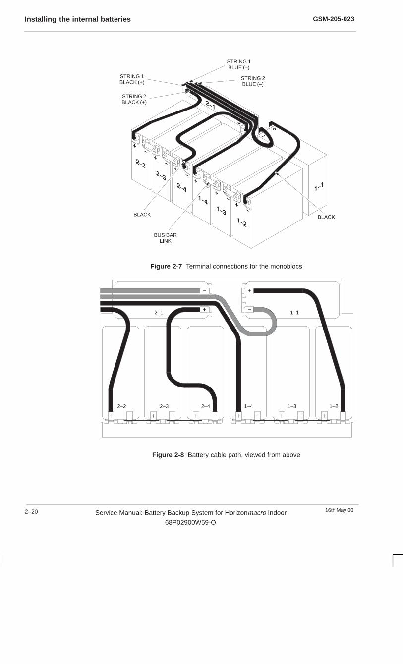
GSM-205-023Installing the internal batteries
16th May 002–20 Service Manual: Battery Backup System for Horizonmacro Indoor
68P02900W59-O
BLACKBLACK
STRING 2BLACK (+)
STRING 1BLACK (+)
STRING 1BLUE (–)
STRING 2BLUE (–)
BUS BARLINK
Figure 2-7 Terminal connections for the monoblocs
2–1 1–1
1–21–31–42–42–32–2
Figure 2-8 Battery cable path, viewed from above

GSM-205-023 Installing the internal batteries
16th May 00 Service Manual: Battery Backup System for Horizonmacro Indoor
68P02900W59-O
2–21
Refitting the bracket, covers and fan tray
Proceed as follows to complete the installation of the internal batteries (letters inparentheses refer to Figure 2-9):
1. Fit the battery retaining bracket and secure in position with the four M6 retainingscrews (A).
2. Refit the air inlet cover and secure in position using the two M6 retaining screws(B).
3. Refit the battery cover and secure in position using the two M6 retaining screws(C).
4. Slide the fan tray into position beneath the rectifier rack. Secure in position usingthe two M6 retaining screws (D).
(D)(D)
(C)(C)
(B)(B)
BATTERYRETAININGBRACKET(HIDDEN)
(A)(A) (A)(A)
Figure 2-9 Refitting the battery retaining bracket, covers and fan tray

GSM-205-023Connecting external battery strings
16th May 002–22 Service Manual: Battery Backup System for Horizonmacro Indoor
68P02900W59-O
Connecting external battery strings
Introduction toexternal batterystrings
In the event of a failure of the main ac supply, the internal BBS batteries will maintainpower to the connected Horizonmacro indoor cabinets for a period depending on thenumber of cabinets connected. Extended battery backup time may be obtained byconnecting a maximum of two additional external battery strings to the BBS.
Safetyprecautions forconnectingexternal batteries
Observe the following safety precautions when connecting external battery strings to theBBS:
� Each additional battery string must be 48 V.
� Ensure that the batteries used comply with the external battery specifications givenin Chapter 1.
� External battery strings MUST have circuit breakers fitted at source.
� Observe the polarity of the EXTERNAL BATTERY connectors on the BBSinterface panel.
� Read the Battery installation safety precautions given earlier in this chapter.
Connecting anexternal batterystring
Proceed as follows to connect an external battery string to the Anderson connectors onthe interface panel:
1. Ensure that the external circuit breaker for the external battery string is switchedOFF.
2. Remove the protective cover from the EXTERNAL BATTERY connectors andstore for future use.
If the external battery string is subsequently removed, the protective coverMUST be refitted.
NOTE
3. Connect the cable pair from the external battery string to the –48 V and 0 VEXTERNAL BATTERY connectors on the BBS as follows:
Negative (–48 V) cable to the blue (–48 V) connector.
Positive (0 V) cable to the black (0 V) connector.
If additional battery strings are added after the BBS has been put into service,the position of SW3 on the control and alarm board must be changed to matchthe total number of battery strings connected (refer to Setting the batterystring dipswitch earlier in this chapter).
NOTE
4. Switch ON the external circuit breaker.
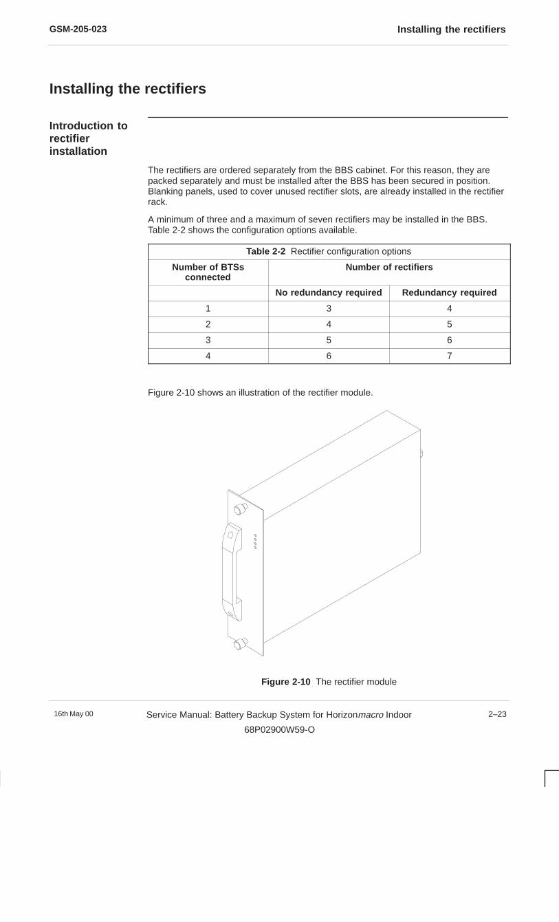
GSM-205-023 Installing the rectifiers
16th May 00 Service Manual: Battery Backup System for Horizonmacro Indoor
68P02900W59-O
2–23
Installing the rectifiers
Introduction torectifierinstallation
The rectifiers are ordered separately from the BBS cabinet. For this reason, they arepacked separately and must be installed after the BBS has been secured in position.Blanking panels, used to cover unused rectifier slots, are already installed in the rectifierrack.
A minimum of three and a maximum of seven rectifiers may be installed in the BBS.Table 2-2 shows the configuration options available.
Table 2-2 Rectifier configuration options
Number of BTSsconnected
Number of rectifiers
No redundancy required Redundancy required
1 3 4
2 4 5
3 5 6
4 6 7
Figure 2-10 shows an illustration of the rectifier module.
Figure 2-10 The rectifier module
GSM-205-023Installing the rectifiers
16th May 002–24 Service Manual: Battery Backup System for Horizonmacro Indoor
68P02900W59-O
Rectifierinstallationprocedure
Handle the rectifier with care. The module weighs 4.6 kg.
CAUTION
Proceed as follows to install the rectifiers:
1. Carefully unpack the rectifiers and inspect for signs of damage.
2. Remove any loose labels attached to the rectifiers.
3. Open the BBS cabinet door.
4. Insert each rectifier in the open slots in the rack, starting from the right-hand side(RECTIFIER 0 position). Ensure the rectifiers are pushed fully home into theirconnectors on the backplane before tightening the M6 retaining screws to a torqueof 3.4 Nm.
The blanking panels maintain the correct airflow through the cabinet. Theymust not be removed from unused rectifier slots unless additional rectifiers areto be fitted.
CAUTION
The procedure for installing the rectifiers is now complete. Figure 2-11 shows a fullyequipped BBS cabinet.

GSM-205-023 Installing the rectifiers
16th May 00 Service Manual: Battery Backup System for Horizonmacro Indoor
68P02900W59-O
2–25
Figure 2-11 Fully equipped BBS cabinet

GSM-205-023Stacking an Horizonmacro indoor cabinet on the BBS cabinet
16th May 002–26 Service Manual: Battery Backup System for Horizonmacro Indoor
68P02900W59-O
Stacking an Horizon macro indoor cabinet on the BBS cabinet
Fitting thestacking bracketonto the BBS
The stacking bracket (see Figure 2-12) must be fitted if an Horizonmacro indoor cabinetis to be stacked on top of the BBS.
M8 SCREW MOUNTING HOLE(FOR BBS)
M10 BOLT MOUNTING HOLE(FOR INDOOR CABINET PLINTH)
Figure 2-12 BBS stacking bracket
The procedure for fitting the stacking bracket onto the top of the BBS is as follows:
1. Remove the eight hex head bolts from the mounting holes in the top of the BBS(see Figure 2-13) and store for future use.
2. Place the stacking bracket on the top of the BBS so that the holes in the stackingbracket feet line up with the mounting holes in the top of the interface panel.Ensure the bracket is the correct way around (see Figure 2-12).
3. Secure the mounting bracket to the BBS by fitting the eight M8 x 16 Torx screws(supplied), and tightening to a torque of 5.4 Nm.
MOUNTINGHOLES
MOUNTINGHOLES
VENTILATED AREA
MOUNTINGHOLES
MOUNTINGHOLES
Figure 2-13 Stacking bracket mounting holes on the BBS

GSM-205-023 Stacking an Horizonmacro indoor cabinet on the BBS cabinet
16th May 00 Service Manual: Battery Backup System for Horizonmacro Indoor
68P02900W59-O
2–27
Fitting anHorizon macroindoor cabinetonto the stackingbracket
The procedure for fitting an Horizonmacro indoor cabinet on the stacking bracket is givenbelow. This procedure assumes that the BBS cabinet has been bolted to the floor and allconnections to the BBS interface panel have already been made
1. Mount the indoor cabinet on its plinth, as described in Installation andConfiguration: Horizonmacro Indoor (GSM-205-423), Fitting cabinet onto plinth .
2. Attach M8 eyebolts to the four lifting holes in the top panel of the indoor cabinet.The holes are identified by the word LIFT next to them.
3. Using suitable lifting equipment, lift the indoor cabinet onto the stacking bracketand align the holes in the plinth with the holes in the top of the stacking bracket.
4. Fit M10 flat washers to four M10 x 20 bolts. Insert the bolts through the holes inthe underside of the top crossmembers of the stacking bracket and screw into theunderside of the plinth. Tighten the bolts to 10 Nm.
5. Make all the connections between the BBS and the Horizonmacro indoor cabinet.
6. Fit the stacking bracket front cover by lining up the pins on the inside of the coverwith the holes in the stacking bracket legs and pushing firmly until the pins lock.
Figure 2-14 shows a completed installation.
STACKINGBRACKET
HORIZONMACROINDOOR CABINET
STACKING BRACKETFRONT COVER
BBSCABINET
Figure 2-14 Fully equipped BBS with stacked Horizonmacro indoor cabinet
GSM-205-023Commissioning the BBS cabinet
16th May 002–28 Service Manual: Battery Backup System for Horizonmacro Indoor
68P02900W59-O
Commissioning the BBS cabinet
Pre-power upchecks
All relevant installation procedures described earlier in this chapter must have beencarried out before the BBS cabinet is commissioned.
Make the following pre-power up checks on the equipment:
� Ensure that the isolator at the ac supply to the BBS cabinet is switched OFF.
� Ensure all BBS circuit breakers and external circuit breakers for external batterystrings (if installed) are switched OFF.
� If an emergency stop switch is not connected to the BBS, ensure that the shortinglink is fitted to the EMERG. STOP socket. The BBS cabinet will power up, butthe batteries will remain disconnected if this link is not fitted.
The protective cover for the EXTERNAL BATTERY connectors must be fittedif the connectors are not used.
WARNING
Powering up theBBS cabinet
This procedure assumes that the pre-power up checks have been completed.
Proceed as follows to power up the BBS cabinet:
1. Switch on the external ac supply to the BBS cabinet.
2. Check the rectifier module LEDs. The yellow I/P HEALTHY LEDs and the greenO/P HEALTHY LEDs should be illuminated. The red alarm LEDs should be unlit.
3. Check the control and alarm board LEDs. The green LEDs, BTS LVD Closed andComms LVD Closed, should be illuminated. All red alarm LEDs should be unlit,with the exception of the Door Open LED. Pressing the door switch should causethe Door Open LED to extinguish and the green Status OK LED should illuminate.
4. Switch on the COMMS circuit breakers (1, 2, 3 or 4, as required).
5. Switch on the BTS circuit breakers (1, 2, 3 or 4, as required).
6. Switch on the battery circuit breakers (STRING 1 and/or STRING 2 as required).
The Battery Charged LED may or may not be illuminated, depending on thecharge state of the batteries. The red OVERCURRENT LEDs on the rectifiersmay be illuminated. This does not necessarily indicate a fault and may be dueto recharging of the batteries.
The OVERCURRENT LEDs may flicker when the BBS is first switched on –this is normal and does not indicate a fault in the system.
NOTE
7. Close the door to ensure correct ventilation.
This completes the BBS power up procedure.
GSM-205-023 Commissioning the BBS cabinet
16th May 00 Service Manual: Battery Backup System for Horizonmacro Indoor
68P02900W59-O
2–29
Powering downthe BBS cabinet
If the BBS cabinet is supplying dc power to Horizonmacro indoor equipmentand/or customer communications equipment, first ensure that this equipmentis powered down before powering down the BBS.
CAUTION
Proceed as follows to power down the BBS cabinet:
1. If external battery strings are connected to the BBS, switch OFF the externalcircuit breakers.
2. Switch all BBS circuit breakers to OFF.
3. Switch OFF the external ac supply to the cabinet.
This completes the BBS power down procedure.


GSM-205-023Decommissioning the BBS cabinet
16th May 002–30 Service Manual: Battery Backup System for Horizonmacro Indoor
68P02900W59-O
Decommissioning the BBS cabinet
Before startingto decommissionthe BBS cabinet
Before starting to decommission the BBS cabinet, ensure that:
� Horizonmacro indoor cabinets and any customer communications equipmentconnected to the BBS are switched off.
� The ac power cable to the BBS cabinet is switched OFF and disconnected atsource.
� The backup battery strings (internal and external) are isolated or disconnected andall circuit breakers on the BBS are in the OFF position.
� The dc power and alarm signal cables are disconnected from the BTS cabinet(s)and any comms equipment powered from the BBS.
� Sufficient packing cartons are available to pack the decommissioned equipment.
Observe the same safety precautions for decommissioning as for installation.
WARNING
Procedure toremove a stackedHorizon macroindoor cabinet
If an Horizonmacro indoor cabinet has been stacked on top of the BBS cabinet, proceedas follows to remove the indoor cabinet:
1. Remove the stacking bracket front cover by applying gentle pressure to the outeredges while easing the cover up and pulling it away from the stacking bracket.Repack the cover ready for transportation.
2. On the underside of the stacking bracket crossmembers, undo and remove thefour M10 bolts and washers that secure the Horizonmacro indoor cabinet to thestacking bracket.
3. Lift the indoor cabinet off the stacking bracket.
4. Undo and remove the eight M8 Torx screws that secure the legs of the stackingbracket to the top of the BBS cabinet.
5. Lift the stacking bracket off the top of the cabinet and repack ready fortransportation.
6. Refit the eight previously stored hex head bolts in the stacking bracket mountingholes on the top of the BBS cabinet.
7. De-install the cabinet itself by following the procedure given next for a floormounted cabinet (see Procedure to decommission the BBS cabinet ).
8. If the equipment is to be returned to Motorola, seal the shipping container andreturn as advised by the Motorola in-country project manager

GSM-205-023 Decommissioning the BBS cabinet
16th May 00 Service Manual: Battery Backup System for Horizonmacro Indoor
68P02900W59-O
2–31
Procedure todecommissionthe BBS cabinet
Proceed as follows to decommission the BBS cabinet:
Stow disconnected cables so that they do not create a hazard to personnelusing the site.
WARNING
Disconnecting cables from the interface panel
If an Horizonmacro indoor cabinet is stacked on top of the BBS, follow theProcedure to remove a stacked Horizon macro indoor cabinet beforedisconnecting the cables from the interface panel.
NOTE
1. Disconnect the ac input power cable from the terminal block on the BBS interfacepanel.
2. If fitted, remove the single phase link from the terminal block and place in a plasticbag (or retrieve from storage if not used). Tape the bag to the back of the terminalblock access plate and then refit the plate.
3. If used, disconnect the external battery string cables from the BBS interface panel.Refit the protective cover to the terminals.
4. Disconnect all BTS and comms power cables from the interface panel.
5. Disconnect the alarm cable from the BTS ALARMS connector on the interfacepanel. If used, disconnect the cable from the AUX ALARMS connector.
6. If fitted, disconnect the emergency stop switch. Refit the shorting link to theEMERG. STOP socket on the interface panel.
7. Disconnect the earth cable from the earth stud on the interface panel.
8. If any cables are not to be used again for other equipment, dispose of safely.
Removing the rectifiers
The cabinet may be transported either with or without the rectifiers installed. However, itis easier to access the battery strings when the rectifiers are removed.
If the rectifiers are to be removed, proceed as follows for each rectifier:
1. Undo the two M6 retaining screws on the rectifier front panel.
The rectifier module weighs 4.6 kg. Handle with care.
CAUTION
2. Using the handle, withdraw the rectifier from the slot, supporting it from beneathwith one hand as it emerges.
3. Repack the rectifier ready for transportation.

GSM-205-023Decommissioning the BBS cabinet
16th May 002–32 Service Manual: Battery Backup System for Horizonmacro Indoor
68P02900W59-O
Removing the internal monoblocs
The internal monoblocs MUST be removed prior to transportation for safetyreasons. Do not attempt to transport the cabinet with the monoblocs installed.
WARNING
Proceed as follows to remove the internal monoblocs:
1. Remove the fan tray, battery cover and air inlet cover to access the monoblocs(refer to Preparing the BBS cabinet for installation earlier in this chapter forinformation on removing these items).
2. Remove the link bars between monoblocs 2–2 to 2–3, 2–3 to 2–4 and 1–2 to 1–3,1–3 to 1–4.
3. Disconnect all the remaining battery cables. Fit an insulating boot over each cabletermination as soon as it is disconnected. Pack the cables, plastic nut covers andlink bars ready for transportation.
4. Undo the four M6 screws that secure the battery retaining bracket in position andremove the bracket.
5. Remove each monobloc in turn and repack ready for transportation.
6. Refit the battery retaining bracket.
De-installing the cabinet (floor mounted only)
Proceed as follows to de-install a BBS cabinet which is bolted to the floor:
1. Undo and remove the four M12 mounting bolts and washers that secure the baseof the BBS cabinet to the floor.
2. Place the packed sundry items (cables, washers, link bars, etc.) in the batterycompartment.
3. Refit the fan tray, air inlet cover and battery cover. Refit the rectifiers, if the cabinetis to be transported with the rectifiers installed.
4. Tape the keys to the cabinet on the inside of the door and then close the door.
5. Move the cabinet to a location where it can be packed ready for transportation.
De-installing the cabinet (mounted on top of an M-Cell 6 battery box)
Proceed as follows to de-install a BBS cabinet which is mounted on top of an M-Cell6indoor battery box:
1. Undo and remove the four M12 mounting bolts and washers that secure the baseof the BBS cabinet to the top of the M-Cell6 battery box.
2. Lift the BBS cabinet off the M-Cell6 battery box and move it to a location where itcan be packed ready for transportation.
3. Place the packed sundry items (cables, washers, link bars, etc.) in the batterycompartment.
4. Refit the fan tray, air inlet cover and battery cover. Refit the rectifiers, if the cabinetis to be transported with the rectifiers installed.
5. Tape the keys to the cabinet on the inside of the door and then close the door.
6. Refit the previously saved plugs into the threaded holes on the top of the M-Cell6battery box.
7. Pack the BBS cabinet ready for transportation.

16th May 00 Service Manual: Battery Backup System for Horizonmacro Indoor
68P02900W59-O
i
Chapter 3
Maintenance procedures for the
battery backup system

GSM-205-023
16th May 00ii Service Manual: Battery Backup System for Horizonmacro Indoor
68P02900W59-O
GSM-205-023
16th May 00 Service Manual: Battery Backup System for Horizonmacro Indoor
68P02900W59-O
iii
Chapter 3Maintenance procedures for the battery backup system i. . . . . . . . . . . . . . .
Introduction to maintenance procedures 3–1. . . . . . . . . . . . . . . . . . . . . . . . . . . . . . . . . . . . . . . Safety 3–1. . . . . . . . . . . . . . . . . . . . . . . . . . . . . . . . . . . . . . . . . . . . . . . . . . . . . . . . . . . . . . . Tools 3–1. . . . . . . . . . . . . . . . . . . . . . . . . . . . . . . . . . . . . . . . . . . . . . . . . . . . . . . . . . . . . . . . Reporting faulty devices 3–1. . . . . . . . . . . . . . . . . . . . . . . . . . . . . . . . . . . . . . . . . . . . . . .
Routine maintenance 3–2. . . . . . . . . . . . . . . . . . . . . . . . . . . . . . . . . . . . . . . . . . . . . . . . . . . . . . . . Routine maintenance intervals 3–2. . . . . . . . . . . . . . . . . . . . . . . . . . . . . . . . . . . . . . . . . . Assumptions 3–2. . . . . . . . . . . . . . . . . . . . . . . . . . . . . . . . . . . . . . . . . . . . . . . . . . . . . . . . . Opening the BBS cabinet door 3–2. . . . . . . . . . . . . . . . . . . . . . . . . . . . . . . . . . . . . . . . . .
6-monthly maintenance procedures 3–3. . . . . . . . . . . . . . . . . . . . . . . . . . . . . . . . . . . . . . . . . . . Type of procedures 3–3. . . . . . . . . . . . . . . . . . . . . . . . . . . . . . . . . . . . . . . . . . . . . . . . . . . . Cleaning air inlets and outlet grilles 3–3. . . . . . . . . . . . . . . . . . . . . . . . . . . . . . . . . . . . . .
12-monthly maintenance procedures 3–4. . . . . . . . . . . . . . . . . . . . . . . . . . . . . . . . . . . . . . . . . . Summary of 12-monthly procedures 3–4. . . . . . . . . . . . . . . . . . . . . . . . . . . . . . . . . . . . . Checking and cleaning fans 3–4. . . . . . . . . . . . . . . . . . . . . . . . . . . . . . . . . . . . . . . . . . . . Checking normal operation 3–5. . . . . . . . . . . . . . . . . . . . . . . . . . . . . . . . . . . . . . . . . . . . .
24-monthly maintenance procedures 3–6. . . . . . . . . . . . . . . . . . . . . . . . . . . . . . . . . . . . . . . . . . Summary of 24-monthly procedures 3–6. . . . . . . . . . . . . . . . . . . . . . . . . . . . . . . . . . . . . Mechanical inspection of the cabinet 3–6. . . . . . . . . . . . . . . . . . . . . . . . . . . . . . . . . . . . .
FRU replacement procedures 3–7. . . . . . . . . . . . . . . . . . . . . . . . . . . . . . . . . . . . . . . . . . . . . . . . Introduction to FRU replacement procedures 3–7. . . . . . . . . . . . . . . . . . . . . . . . . . . . . . Isolating the BBS cabinet 3–7. . . . . . . . . . . . . . . . . . . . . . . . . . . . . . . . . . . . . . . . . . . . . . . FRU list 3–7. . . . . . . . . . . . . . . . . . . . . . . . . . . . . . . . . . . . . . . . . . . . . . . . . . . . . . . . . . . . . . Torque values 3–7. . . . . . . . . . . . . . . . . . . . . . . . . . . . . . . . . . . . . . . . . . . . . . . . . . . . . . . . FRU view of the BBS cabinet 3–8. . . . . . . . . . . . . . . . . . . . . . . . . . . . . . . . . . . . . . . . . . .
Replacing the control and alarm board 3–9. . . . . . . . . . . . . . . . . . . . . . . . . . . . . . . . . . . . . . . . . Introduction to control and alarm board replacement 3–9. . . . . . . . . . . . . . . . . . . . . . . Replacement procedure for the control and alarm board 3–9. . . . . . . . . . . . . . . . . . . .
Replacing a rectifier module 3–10. . . . . . . . . . . . . . . . . . . . . . . . . . . . . . . . . . . . . . . . . . . . . . . . . . Introduction to rectifier replacement 3–10. . . . . . . . . . . . . . . . . . . . . . . . . . . . . . . . . . . . . . Replacement procedure for a rectifier 3–11. . . . . . . . . . . . . . . . . . . . . . . . . . . . . . . . . . . .
Replacing the fan tray 3–12. . . . . . . . . . . . . . . . . . . . . . . . . . . . . . . . . . . . . . . . . . . . . . . . . . . . . . . Introduction to fan tray replacement 3–12. . . . . . . . . . . . . . . . . . . . . . . . . . . . . . . . . . . . . Replacement procedure for the fan tray 3–12. . . . . . . . . . . . . . . . . . . . . . . . . . . . . . . . . .
Replacing the internal batteries 3–13. . . . . . . . . . . . . . . . . . . . . . . . . . . . . . . . . . . . . . . . . . . . . . . Introduction to internal battery replacement 3–13. . . . . . . . . . . . . . . . . . . . . . . . . . . . . . . Internal battery replacement procedure 3–14. . . . . . . . . . . . . . . . . . . . . . . . . . . . . . . . . . .
Replacing the BBS cabinet door 3–18. . . . . . . . . . . . . . . . . . . . . . . . . . . . . . . . . . . . . . . . . . . . . . Introduction to door replacement 3–18. . . . . . . . . . . . . . . . . . . . . . . . . . . . . . . . . . . . . . . . Views of the cabinet door 3–18. . . . . . . . . . . . . . . . . . . . . . . . . . . . . . . . . . . . . . . . . . . . . . Door replacement procedure 3–19. . . . . . . . . . . . . . . . . . . . . . . . . . . . . . . . . . . . . . . . . . . .

GSM-205-023
16th May 00iv Service Manual: Battery Backup System for Horizonmacro Indoor
68P02900W59-O
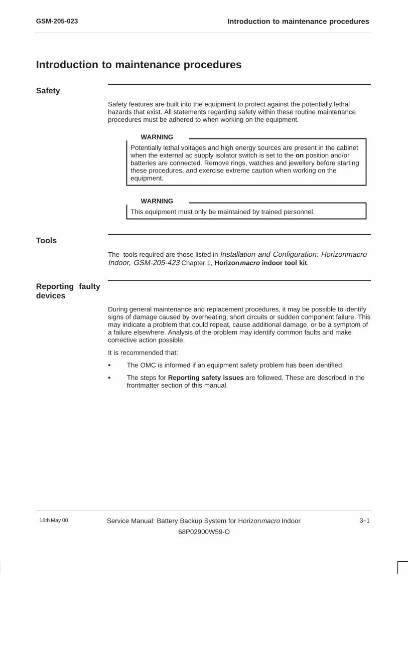
GSM-205-023 Introduction to maintenance procedures
16th May 00 Service Manual: Battery Backup System for Horizonmacro Indoor
68P02900W59-O
3–1
Introduction to maintenance procedures
Safety
Safety features are built into the equipment to protect against the potentially lethalhazards that exist. All statements regarding safety within these routine maintenanceprocedures must be adhered to when working on the equipment.
Potentially lethal voltages and high energy sources are present in the cabinetwhen the external ac supply isolator switch is set to the on position and/orbatteries are connected. Remove rings, watches and jewellery before startingthese procedures, and exercise extreme caution when working on theequipment.
WARNING
This equipment must only be maintained by trained personnel.
WARNING
Tools
The tools required are those listed in Installation and Configuration: HorizonmacroIndoor, GSM-205-423 Chapter 1, Horizon macro indoor tool kit .
Reporting faultydevices
During general maintenance and replacement procedures, it may be possible to identifysigns of damage caused by overheating, short circuits or sudden component failure. Thismay indicate a problem that could repeat, cause additional damage, or be a symptom ofa failure elsewhere. Analysis of the problem may identify common faults and makecorrective action possible.
It is recommended that:
� The OMC is informed if an equipment safety problem has been identified.
� The steps for Reporting safety issues are followed. These are described in thefrontmatter section of this manual.

GSM-205-023Routine maintenance
16th May 003–2 Service Manual: Battery Backup System for Horizonmacro Indoor
68P02900W59-O
Routine maintenance
Routinemaintenanceintervals
Routine maintenance for the battery backup system is recommended at the intervalsshown in Table 3-1:
Table 3-1 Routine maintenance schedule
6 months 12 months 24 months
Ensure that cabinet airinlets and outlet grilles arenot blocked.
Check normal operation,including fans. Also cableintegrity and state of allconnections.
Inspect general mechanicalcondition of the cabinet.
These procedures are described in subsequent sections of this chapter, one to cover6-monthly, one for 12-monthly, and one for 24-monthly.
The control and alarm board performs an automatic battery test on a monthlycycle. However, a manual battery test can be performed at any time (refer toControl and alarm board front panel controls and indicators , Battery test,in Chapter 1 for further information).
NOTE
Assumptions
Any requirement to open the BBS cabinet door is assumed to be done in procedures.Closing the door is assumed to be done at the end of any procedure.
Opening the BBScabinet door
The door lock is a trigger latch. The door is operated as follows:
1. Insert the correct key into the lock and turn.
2. Press the middle square panel by the lock to release the lock.
3. Open the door to the 95� locking position.
Avoid damaging the honeycomb door vent.
CAUTION
If the equipment is active, a Door 2 open alarm will be generated to the OMC.
NOTE
4. To open the door to 130�, lift up the middle of the slide arm.
5. To close the door, lift up the middle of the slide arm, close the door firmly and lock.
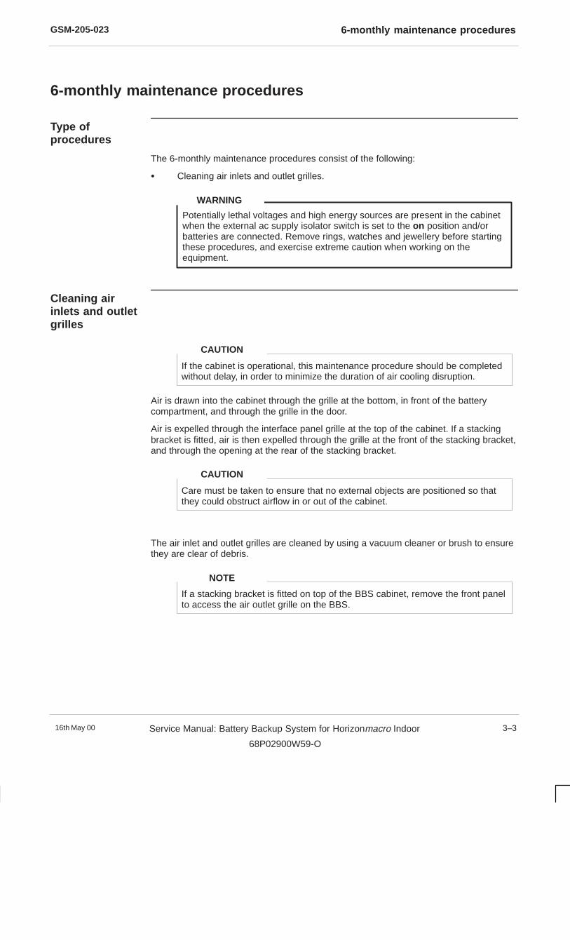
GSM-205-023 6-monthly maintenance procedures
16th May 00 Service Manual: Battery Backup System for Horizonmacro Indoor
68P02900W59-O
3–3
6-monthly maintenance procedures
Type ofprocedures
The 6-monthly maintenance procedures consist of the following:
� Cleaning air inlets and outlet grilles.
Potentially lethal voltages and high energy sources are present in the cabinetwhen the external ac supply isolator switch is set to the on position and/orbatteries are connected. Remove rings, watches and jewellery before startingthese procedures, and exercise extreme caution when working on theequipment.
WARNING
Cleaning airinlets and outletgrilles
If the cabinet is operational, this maintenance procedure should be completedwithout delay, in order to minimize the duration of air cooling disruption.
CAUTION
Air is drawn into the cabinet through the grille at the bottom, in front of the batterycompartment, and through the grille in the door.
Air is expelled through the interface panel grille at the top of the cabinet. If a stackingbracket is fitted, air is then expelled through the grille at the front of the stacking bracket,and through the opening at the rear of the stacking bracket.
Care must be taken to ensure that no external objects are positioned so thatthey could obstruct airflow in or out of the cabinet.
CAUTION
The air inlet and outlet grilles are cleaned by using a vacuum cleaner or brush to ensurethey are clear of debris.
If a stacking bracket is fitted on top of the BBS cabinet, remove the front panelto access the air outlet grille on the BBS.
NOTE
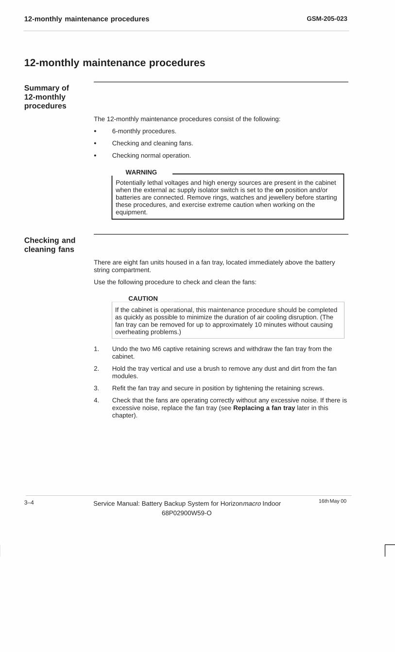
GSM-205-02312-monthly maintenance procedures
16th May 003–4 Service Manual: Battery Backup System for Horizonmacro Indoor
68P02900W59-O
12-monthly maintenance procedures
Summary of12-monthlyprocedures
The 12-monthly maintenance procedures consist of the following:
� 6-monthly procedures.
� Checking and cleaning fans.
� Checking normal operation.
Potentially lethal voltages and high energy sources are present in the cabinetwhen the external ac supply isolator switch is set to the on position and/orbatteries are connected. Remove rings, watches and jewellery before startingthese procedures, and exercise extreme caution when working on theequipment.
WARNING
Checking andcleaning fans
There are eight fan units housed in a fan tray, located immediately above the batterystring compartment.
Use the following procedure to check and clean the fans:
If the cabinet is operational, this maintenance procedure should be completedas quickly as possible to minimize the duration of air cooling disruption. (Thefan tray can be removed for up to approximately 10 minutes without causingoverheating problems.)
CAUTION
1. Undo the two M6 captive retaining screws and withdraw the fan tray from thecabinet.
2. Hold the tray vertical and use a brush to remove any dust and dirt from the fanmodules.
3. Refit the fan tray and secure in position by tightening the retaining screws.
4. Check that the fans are operating correctly without any excessive noise. If there isexcessive noise, replace the fan tray (see Replacing a fan tray later in thischapter).

GSM-205-023 12-monthly maintenance procedures
16th May 00 Service Manual: Battery Backup System for Horizonmacro Indoor
68P02900W59-O
3–5
Checking normaloperation
Check normal operation of the BBS by visual inspection as follows:
1. Check the inside of the cabinet and note any signs of physical damage,overheating, loose connections, or badly fitting components. Take appropriateaction to correct the damage, and inform the OMC.
2. Note the LEDs lit on modules shown in Table 3-2 to ensure the correct functioningof the cabinet. Inform the OMC if any red LEDs are lit on the control and alarmboard (with the exception of the Door Open alarm).
Table 3-2 Normal LED indication of cabinet modules
Equipment withLEDs
Colour of LEDs lit Notes
Rectifier modules GREEN (O/P healthy)
YELLOW (I/P healthy)–
–
Control and alarmboard
GREEN (BTS LVD closed)
GREEN (Comms LVD closed)
GREEN (Battery Charged)
RED (Door Open)
GREEN (Status OK)
–
–If this LED is flashing, itindicates that a battery test isin progress.
–The Status OK LED is notaffected by the Door Openalarm.
GSM-205-02324-monthly maintenance procedures
16th May 003–6 Service Manual: Battery Backup System for Horizonmacro Indoor
68P02900W59-O
24-monthly maintenance procedures
Summary of24-monthlyprocedures
Potentially lethal voltages and high energy sources are present in the cabinetwhen the external ac supply isolator switch is set to the on position and/orbatteries are connected. Remove rings, watches and jewellery before startingthese procedures, and exercise extreme caution when working on theequipment.
WARNING
The 24-monthly maintenance procedures involve the following:
� 6-monthly procedures.
� 12-monthly procedures.
� Mechanical inspection of the cabinet.
Mechanicalinspection of thecabinet
The following procedures must be performed every 24 months.
Inspecting the cabinet exterior
Inspect the cabinet exterior by checking the cabinet interface panel connections for signsof overheating and security of attachment.
Inspecting the door
Inspect the door using the following procedure:
1. Check the cabinet door for distortion, security and correct operation.
2. Check hinges for damage, security and correct operation.
3. Check the door earth connection for damage and security.
4. Check the door lock mechanism and inspect for ease of operation. Lubricate themechanism with light grease. Ensure that lubricated surfaces are grit-free.
Inspecting the cabinet interior
Inspect the cabinet interior using the following procedure:
1. Check all rack mounted modules for security of attachment.
2. Carry out a visual check of all wiring for signs of overheating and security ofattachment.
Do not overstress the earth connections as this may damage the connectorand reduce the protective function.
WARNING
GSM-205-023 FRU replacement procedures
16th May 00 Service Manual: Battery Backup System for Horizonmacro Indoor
68P02900W59-O
3–7
FRU replacement procedures
Introduction toFRU replacementprocedures
Potentially lethal voltages and high energy sources are present in theenclosure when the external ac supply isolator switch is set to the on positionand/or batteries are connected. Remove rings, watches and jewellery beforestarting these procedures, and exercise extreme caution when working on theequipment.
WARNING
This chapter provides information on the replacement of field replaceable units (FRUs) inthe BBS. Only components classed as FRUs are described in this chapter.
All FRUs may be hot swapped while the BBS is operational. There is no requirement topower down the BBS.
Customers requiring replacement of items not classed as FRUs should contacttheir local Motorola office for availability of parts, and seek Motorola advice forreplacement procedures.
NOTE
Any requirement to open the cabinet door is assumed in procedures. Closing and lockingthe door is assumed at the end of any procedure.
Where customers wish to perform a minor repair on a FRU to save the cost of fullreplacement, they should consult Motorola for more detailed procedures or replacementcomponents.
Isolating the BBScabinet
All FRUs described in this chapter are “hot swappable” and do not require the BBScabinet to be isolated.
FRU list
The following is a list of FRUs used in this equipment:
� Control and alarm board.
� Rectifier modules.
� Fan tray.
� Battery strings.
� Cabinet door
Torque values
For torque values used during repair procedures, refer to Installation and Configuration:Horizonmacro Indoor (GSM-205-423) Site requirements and considerations .

GSM-205-023FRU replacement procedures
16th May 003–8 Service Manual: Battery Backup System for Horizonmacro Indoor
68P02900W59-O
FRU view of theBBS cabinet
Figure 3-1 shows the BBS cabinet with FRUs identified.
MONOBLOCS
FAN TRAY
RECTIFIERMODULES
CONTROLAND ALARM
BOARD
Figure 3-1 BBS cabinet showing FRU components (excluding door)
GSM-205-023 Replacing the control and alarm board
16th May 00 Service Manual: Battery Backup System for Horizonmacro Indoor
68P02900W59-O
3–9
Replacing the control and alarm board
Introduction tocontrol and alarmboardreplacement
This procedure describes how to remove and replace the control and alarm board in theBBS.
Potentially lethal ac voltages and other high energy sources are present whenthe BBS cabinet is connected to an ac power source. In addition, –48 V dc ispresent when internal or external batteries are fitted.
WARNING
Replacing the control and alarm board does not require the removal of power.
Notify the OMC of imminent repair activity.
Replacementprocedure for thecontrol and alarmboard
To remove the control and alarm board
1. Unscrew the two M6 captive screws that secure the control and alarm board inposition.
Handle the control and alarm board with care.
CAUTION
2. Withdraw the control and alarm board from its slot, supporting it from beneath withone hand as it emerges. Place it safely to one side.
The procedure for removing the control and alarm board is now complete.
To install a replacement control and alarm board
1. Set SW3 on the replacement board to the same position as on the faulty board.
2. Insert the control and alarm board into its slot.
3. Ensure that the board is pushed fully home into its connector on the backplane andthen tighten the two M6 screws to a torque of 3.4 Nm.
4. Check the operation of the control and alarm board LEDs. The four green statusLEDs (BTS LVD Closed, Comms LVD Closed, Battery Charged and Status OK)should be illuminated and all red alarm LEDs, with the exception of the Door openLED, should be unlit.
The procedure for installing a replacement control and alarm board is now complete.
Inform the OMC that the replacement control and alarm board has been installed and logthe maintenance activity.
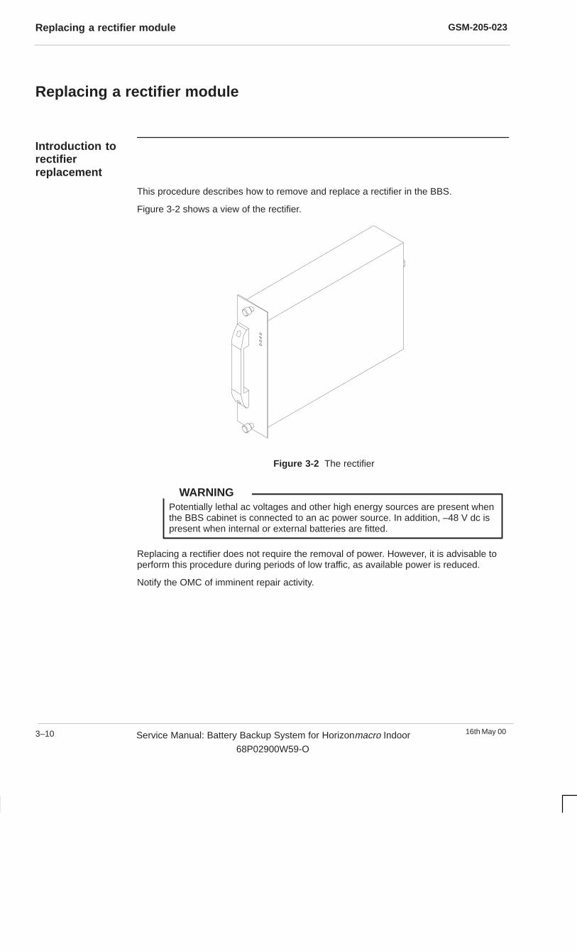
GSM-205-023Replacing a rectifier module
16th May 003–10 Service Manual: Battery Backup System for Horizonmacro Indoor
68P02900W59-O
Replacing a rectifier module
Introduction torectifierreplacement
This procedure describes how to remove and replace a rectifier in the BBS.
Figure 3-2 shows a view of the rectifier.
Figure 3-2 The rectifier
Potentially lethal ac voltages and other high energy sources are present whenthe BBS cabinet is connected to an ac power source. In addition, –48 V dc ispresent when internal or external batteries are fitted.
WARNING
Replacing a rectifier does not require the removal of power. However, it is advisable toperform this procedure during periods of low traffic, as available power is reduced.
Notify the OMC of imminent repair activity.

GSM-205-023 Replacing a rectifier module
16th May 00 Service Manual: Battery Backup System for Horizonmacro Indoor
68P02900W59-O
3–11
Replacementprocedure for arectifier
To remove a rectifier
1. Unscrew the two M6 captive screws that secure the rectifier in position.
The rectifier module weighs 4.6 kg. Handle with care.
CAUTION
2. Using the handle, withdraw the rectifier from its slot, supporting it from beneathwith one hand as it emerges. Place it safely to one side.
The procedure for removing the rectifier is now complete.
To install a replacement rectifier
1. Repeat the removal procedure in reverse order.
2. Ensure that the rectifier is pushed fully home into its connector on the backplanebefore tightening the two M6 screws to a torque of 3.4 Nm.
3. Check the operation of the rectifier LEDs. The yellow I/P HEALTHY and green O/PHEALTHY LEDs should be illuminated.
The procedure for installing a replacement rectifier is now complete.
Inform the OMC that the replacement rectifier has been installed and log themaintenance activity.

GSM-205-023Replacing the fan tray
16th May 003–12 Service Manual: Battery Backup System for Horizonmacro Indoor
68P02900W59-O
Replacing the fan tray
Introduction tofan trayreplacement
The fan tray is mounted immediately above the battery string compartment and containseight fan units.
This procedure describes how to remove and replace the fan tray.
Potentially lethal ac voltages and other high energy sources are present whenthe BBS cabinet is connected to an ac power source. In addition, –48 V dc willbe present when internal or external batteries are fitted.
WARNING
Replacing the fan tray does not require the removal of power.
Notify the OMC of imminent repair activity.
Replacementprocedure for thefan tray
If the cabinet is operational, this procedure should be completed as quickly aspossible to minimize the duration of air cooling disruption. (The BBS willoperate without overheating problems for up to approximately 10 minutes withthe fan tray removed.)
CAUTION
To remove the fan tray
1. Unscrew the two front panel captive M6 screws that secure the fan tray in position.
2. Withdraw the fan tray from the cabinet, supporting it from beneath with one handas it emerges. Place it safely to one side.
The procedure for removing the fan tray is now complete.
To install a replacement fan tray
1. Insert the fan tray into its slot beneath the rectifiers.
2. Ensure that the tray is pushed fully home into its connector on the backplane.Tighten the two M6 retaining screws to a torque of 3.4 Nm.
The procedure for installing a replacement fan tray is now complete.
Inform the OMC that the replacement fan tray has been installed and log themaintenance activity.
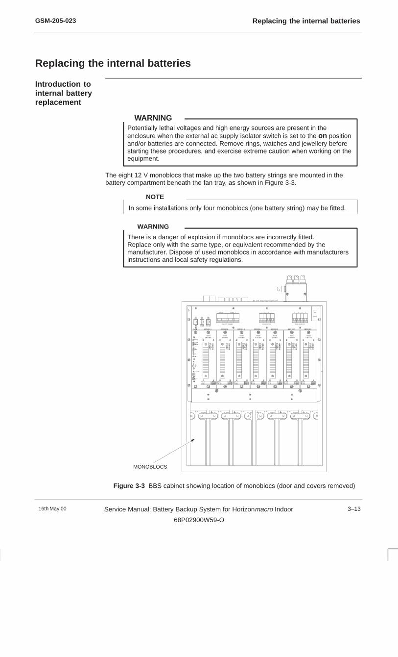
GSM-205-023 Replacing the internal batteries
16th May 00 Service Manual: Battery Backup System for Horizonmacro Indoor
68P02900W59-O
3–13
Replacing the internal batteries
Introduction tointernal batteryreplacement
Potentially lethal voltages and high energy sources are present in theenclosure when the external ac supply isolator switch is set to the on positionand/or batteries are connected. Remove rings, watches and jewellery beforestarting these procedures, and exercise extreme caution when working on theequipment.
WARNING
The eight 12 V monoblocs that make up the two battery strings are mounted in thebattery compartment beneath the fan tray, as shown in Figure 3-3.
In some installations only four monoblocs (one battery string) may be fitted.
NOTE
There is a danger of explosion if monoblocs are incorrectly fitted.Replace only with the same type, or equivalent recommended by themanufacturer. Dispose of used monoblocs in accordance with manufacturersinstructions and local safety regulations.
WARNING
MONOBLOCS
Figure 3-3 BBS cabinet showing location of monoblocs (door and covers removed)
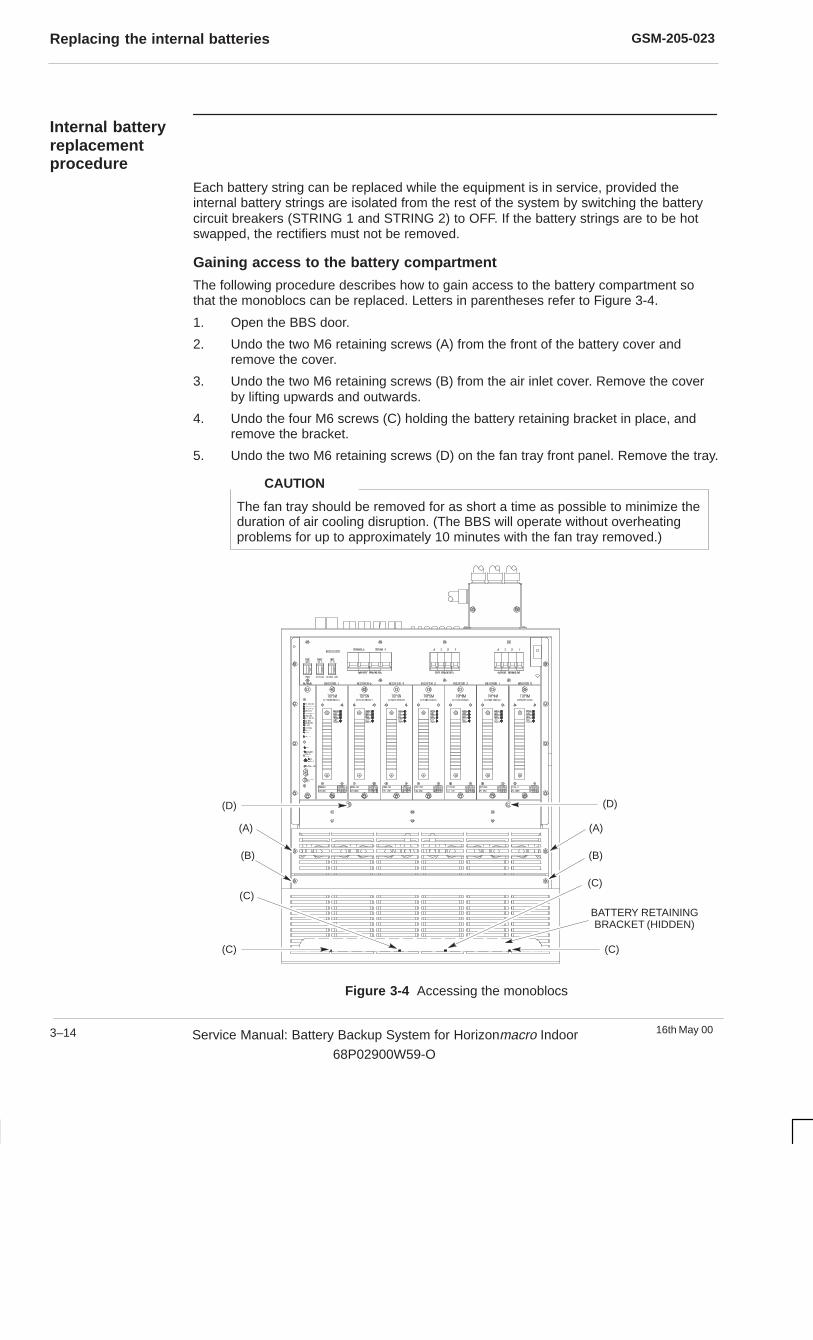
GSM-205-023Replacing the internal batteries
16th May 003–14 Service Manual: Battery Backup System for Horizonmacro Indoor
68P02900W59-O
Internal batteryreplacementprocedure
Each battery string can be replaced while the equipment is in service, provided theinternal battery strings are isolated from the rest of the system by switching the batterycircuit breakers (STRING 1 and STRING 2) to OFF. If the battery strings are to be hotswapped, the rectifiers must not be removed.
Gaining access to the battery compartment
The following procedure describes how to gain access to the battery compartment sothat the monoblocs can be replaced. Letters in parentheses refer to Figure 3-4.
1. Open the BBS door.
2. Undo the two M6 retaining screws (A) from the front of the battery cover andremove the cover.
3. Undo the two M6 retaining screws (B) from the air inlet cover. Remove the coverby lifting upwards and outwards.
4. Undo the four M6 screws (C) holding the battery retaining bracket in place, andremove the bracket.
5. Undo the two M6 retaining screws (D) on the fan tray front panel. Remove the tray.
The fan tray should be removed for as short a time as possible to minimize theduration of air cooling disruption. (The BBS will operate without overheatingproblems for up to approximately 10 minutes with the fan tray removed.)
CAUTION
(D)(D)
(A)(A)
(B)(B)
BATTERY RETAININGBRACKET (HIDDEN)
(C)(C)
(C)(C)
Figure 3-4 Accessing the monoblocs

GSM-205-023 Replacing the internal batteries
16th May 00 Service Manual: Battery Backup System for Horizonmacro Indoor
68P02900W59-O
3–15
Removing the old monoblocs
The following procedure details how to disconnect and remove the monoblocs.
Insulated tools must be used when disconnecting monobloc terminals.
Ensure the two double pole circuit breakers (STRING 1 and STRING 2)located on the BBS circuit breaker panel are switched to OFF.
WARNING
1. Referring to Figure 3-5, disconnect links 2–2 to 2–3, 2–3 to 2–4 and 1–2 to 1–3,1–3 to 1–4.
2. Disconnect all the remaining cables to the monobloc terminals. Fit an insulatingboot over each cable termination as soon as it is disconnected.
3. Remove each of the monoblocs and place safely aside for disposal in accordancewith the manufacturer’s instructions and local safety regulations.
BLACKBLACK
STRING 2BLACK (+)
STRING 1BLACK (+)
STRING 1BLUE (–)
STRING 2BLUE (–)
BUS BARLINK
Figure 3-5 Terminal connections for monoblocs making up two battery strings

GSM-205-023Replacing the internal batteries
16th May 003–16 Service Manual: Battery Backup System for Horizonmacro Indoor
68P02900W59-O
Fitting replacement monoblocsThe following procedure describes how to install and connect up the new monoblocs.
Read Battery installation safety precautions in Chapter 2 beforeattempting to install the new monoblocs.
There is a risk of explosion if the monoblocs are installed incorrectly.
WARNING
Remove the new monoblocs, terminal bolts and spring washers from their packaging.Smear a small amount of light grease onto the bolt threads prior to fitting. Refer toFigure 3-6 and proceed as follows to install either one or two replacement battery stringsin the BBS cabinet:
Installing a single battery string1. Slide monobloc 1–1 into position. Fit the bolt and spring washer to the red sleeved
(+) termination of the black cable marked “STR1 BATT1 +VE” and connect it to thered (+) terminal on the monobloc. Tighten the bolt to 5 Nm and fit the nut cap.
Fit the bolt and spring washer to the blue sleeved (–) termination of the blue cablemarked “STR1 BATT1 –VE” and connect it to the blue (–) terminal on themonobloc. Tighten the bolt to 5 Nm and fit the nut cap.
2. Slide monobloc 1–2 into position and connect the blue sleeved (–) termination ofthe black cable marked “STR1 BATT2 –VE” to the blue (–) terminal on themonobloc. Tighten the bolt to 5 Nm and fit the nut cap.
3. Slide monobloc 1–3 into position.
4. Slide monobloc 1–4 into position and connect the red sleeved (+) termination ofthe black cable marked “STR1 BATT4 +VE” to the red (+) terminal on themonobloc. Tighten the bolt to 5 Nm and fit the nut cap.
5. Check that all cables in string 1 are connected correctly and do not cross overeach other (see Figure 3-6) and then fit the bus bar links between monoblocs 1–2and 1–3, 1–3 and 1–4. Tighten the bolts to 5 Nm and fit the nut caps.
Installing two battery strings1. Slide monobloc 2–1 into position. Fit the bolt and spring washer to the blue
sleeved (–) termination of the blue cable marked “STR2 BATT1 –VE” and connectit to the blue (–) terminal on the monobloc. Tighten the bolt to 5 Nm and fit the nutcap.
Fit the bolt and spring washer to the red sleeved (+) termination of the black cablemarked “STR2 BATT1 +VE” and connect it to the red (+) terminal on themonobloc. Tighten the bolt to 5 Nm and fit the nut cap.
2. Slide monobloc 2–2 into position and connect the red sleeved (+) termination ofthe black cable marked “STR2 BATT2 +VE” to the red (+) terminal on themonobloc. Tighten the bolt to 5 Nm and fit the nut cap.
3. Slide monobloc 2–3 into position.
4. Slide monobloc 2–4 into position and connect the blue sleeved (–) termination ofthe black cable marked “STR2 BATT4 –VE” to the blue (–) terminal on themonobloc. Tighten the bolt to 5 Nm and fit the nut cap.
5. Install the first battery string, as described previously in Installing a singlebattery string . Note that it may be easier to make the connections to monobloc1–1 before it is slid into position.
6. Check that all cables in string 2 are connected correctly and do not cross overeach other (see Figure 3-6) and fit the bus bar links between monoblocs 2–2 and2–3, 2–3 and 2–4. Tighten the bolts to 5 Nm and fit the nut caps.
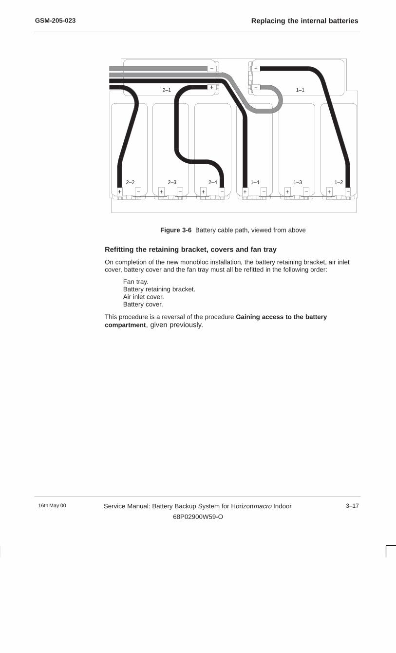
GSM-205-023 Replacing the internal batteries
16th May 00 Service Manual: Battery Backup System for Horizonmacro Indoor
68P02900W59-O
3–17
2–1 1–1
1–21–31–42–42–32–2
Figure 3-6 Battery cable path, viewed from above
Refitting the retaining bracket, covers and fan tray
On completion of the new monobloc installation, the battery retaining bracket, air inletcover, battery cover and the fan tray must all be refitted in the following order:
Fan tray.Battery retaining bracket.Air inlet cover.Battery cover.
This procedure is a reversal of the procedure Gaining access to the batterycompartment , given previously.

GSM-205-023Replacing the BBS cabinet door
16th May 003–18 Service Manual: Battery Backup System for Horizonmacro Indoor
68P02900W59-O
Replacing the BBS cabinet door
Introduction todoor replacement
The door is essential for the correct operation of the cabinet ventilation system, and alsoprovides protection for the equipment inside. It is therefore essential that the doorreplacement procedure is carried out in one session, and the cabinet then secured.
Views of thecabinet door
Figure 3-7 shows views of the inside and outside of the BBS cabinet door.
VENTILATIONGRILLE
EXTERNAL VIEW
TRIGGERLATCH
INTERNAL VIEW
VERTICAL AIRBAFFLE
DOOR ALARMBRACKET
HONEYCOMBVENTILATION
DOOR STOPBRACKET
Figure 3-7 The BBS cabinet door
GSM-205-023 Replacing the BBS cabinet door
16th May 00 Service Manual: Battery Backup System for Horizonmacro Indoor
68P02900W59-O
3–19
Doorreplacementprocedure
Removing the faulty door
Open the door and proceed as follows to remove:
1. On the inside of the cabinet, undo the M6 nut that secures the door earth cable tothe cabinet. Retain the nut for re-use.
2. Slacken the M6 securing screw on the sliding arm, then unhook the sliding armfrom the cabinet attachment point by lifting.
3. Open the door to about 90° and then lift the door off its hinges.
4. Store the door and its keys ready for transport/disposal.
Fitting a replacement door
Proceed as follows to fit a replacement door:
Take care to avoid damaging the honeycomb vent when fitting the door.
CAUTION
1. Hold the door at about 90° to the cabinet and then lift the door onto its hinges.
2. Attach the door earth cable to the cabinet using the M6 nut. Tighten to a torque of3.4 Nm.
3. Fit the sliding arm onto its attachment point on the cabinet and turn the M6 nutseveral turns (do not fully tighten).
4. Check the operation of the new door and ensure that the keys supplied are thecorrect ones for the lock before closing the door.
Unlike the original BBS cabinet door, a replacement door does not have abattery installation instruction label on the inside panel. In such cases wherethe door has been replaced, the internal battery replacement procedure givenin this chapter must be followed.
NOTE

GSM-205-023Replacing the BBS cabinet door
16th May 003–20 Service Manual: Battery Backup System for Horizonmacro Indoor
68P02900W59-O
16th May 00 Service Manual: Battery Backup System for Horizonmacro Indoor
68P02900W59-O
i
Chapter 4
Parts list for the battery backup
system

GSM-205-023
16th May 00ii Service Manual: Battery Backup System for Horizonmacro Indoor
68P02900W59-O

GSM-205-023
16th May 00 Service Manual: Battery Backup System for Horizonmacro Indoor
68P02900W59-O
iii
Chapter 4Parts list for the battery backup system i. . . . . . . . . . . . . . . . . . . . . . . . . . . . . .
Parts list information 4–1. . . . . . . . . . . . . . . . . . . . . . . . . . . . . . . . . . . . . . . . . . . . . . . . . . . . . . . . Introduction to BBS parts list information 4–1. . . . . . . . . . . . . . . . . . . . . . . . . . . . . . . . . Ordering method 4–1. . . . . . . . . . . . . . . . . . . . . . . . . . . . . . . . . . . . . . . . . . . . . . . . . . . . . . Spare parts list 4–1. . . . . . . . . . . . . . . . . . . . . . . . . . . . . . . . . . . . . . . . . . . . . . . . . . . . . . .

GSM-205-023
16th May 00iv Service Manual: Battery Backup System for Horizonmacro Indoor
68P02900W59-O
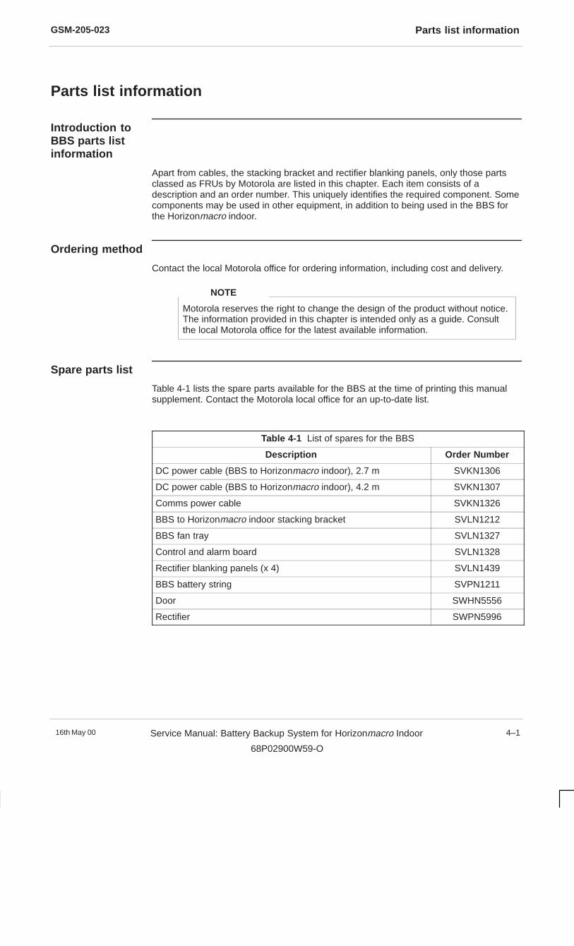
GSM-205-023 Parts list information
16th May 00 Service Manual: Battery Backup System for Horizonmacro Indoor
68P02900W59-O
4–1
Parts list information
Introduction toBBS parts listinformation
Apart from cables, the stacking bracket and rectifier blanking panels, only those partsclassed as FRUs by Motorola are listed in this chapter. Each item consists of adescription and an order number. This uniquely identifies the required component. Somecomponents may be used in other equipment, in addition to being used in the BBS forthe Horizonmacro indoor.
Ordering method
Contact the local Motorola office for ordering information, including cost and delivery.
Motorola reserves the right to change the design of the product without notice.The information provided in this chapter is intended only as a guide. Consultthe local Motorola office for the latest available information.
NOTE
Spare parts list
Table 4-1 lists the spare parts available for the BBS at the time of printing this manualsupplement. Contact the Motorola local office for an up-to-date list.
Table 4-1 List of spares for the BBS
Description Order Number
DC power cable (BBS to Horizonmacro indoor), 2.7 m SVKN1306
DC power cable (BBS to Horizonmacro indoor), 4.2 m SVKN1307
Comms power cable SVKN1326
BBS to Horizonmacro indoor stacking bracket SVLN1212
BBS fan tray SVLN1327
Control and alarm board SVLN1328
Rectifier blanking panels (x 4) SVLN1439
BBS battery string SVPN1211
Door SWHN5556
Rectifier SWPN5996

GSM-205-023Parts list information
16th May 004–2 Service Manual: Battery Backup System for Horizonmacro Indoor
68P02900W59-O

16th May 00 Service Manual: Battery Backup System for Horizonmacro Indoor
68P02900W59-O
i
Index

GSM-205-023
16th May 00ii Service Manual: Battery Backup System for Horizonmacro Indoor
68P02900W59-O
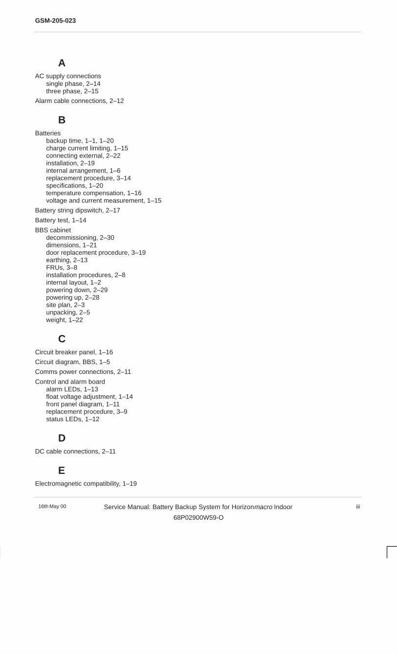
GSM-205-023
16th May 00 Service Manual: Battery Backup System for Horizonmacro Indoor
68P02900W59-O
iii
AAC supply connections
single phase, 2–14three phase, 2–15
Alarm cable connections, 2–12
BBatteries
backup time, 1–1, 1–20charge current limiting, 1–15connecting external, 2–22installation, 2–19internal arrangement, 1–6replacement procedure, 3–14specifications, 1–20temperature compensation, 1–16voltage and current measurement, 1–15
Battery string dipswitch, 2–17
Battery test, 1–14
BBS cabinetdecommissioning, 2–30dimensions, 1–21door replacement procedure, 3–19earthing, 2–13FRUs, 3–8installation procedures, 2–8internal layout, 1–2powering down, 2–29powering up, 2–28site plan, 2–3unpacking, 2–5weight, 1–22
CCircuit breaker panel, 1–16
Circuit diagram, BBS, 1–5
Comms power connections, 2–11
Control and alarm boardalarm LEDs, 1–13float voltage adjustment, 1–14front panel diagram, 1–11replacement procedure, 3–9status LEDs, 1–12
DDC cable connections, 2–11
EElectromagnetic compatibility, 1–19

GSM-205-023
16th May 00iv Service Manual: Battery Backup System for Horizonmacro Indoor
68P02900W59-O
Emergency stop, 1–17, 2–13
FFan tray
alarms, 1–7cleaning, 3–4replacement procedure, 3–12
Fuses, 1–21
HHorizonmacro indoor cabinet
mounting on stacking bracket, 2–27removal, 2–30
IInterface panel
alarm and signal connections, 1–17, 1–18diagram, 1–3, 2–10disconnecting cables, 2–31
LLVD contactors, 1–4, 1–16
MM–Cell6 indoor battery box, 2–6, 2–9, 2–32
PPackaging, 2–4
RRectifier
front panel LEDs, 1–9functional description, 1–9functional diagram, 1–10installation, 2–23replacement procedure, 3–11requirements, 1–8
Reset button, control and alarm board, 1–13
Routine maintenance schedule, 3–2
SSpares list, 4–1
GSM-205-023
16th May 00 Service Manual: Battery Backup System for Horizonmacro Indoor
68P02900W59-O
v
Stacking bracketdimensions, 1–21installation, 2–26removal, 2–30
Supply voltage, 1–19