Embed Size (px)
Citation preview
Basis of Design Report Site Preparation Project
Sacramento Regional County Sanitation District
DRAFT
August 2013
Draft Basis of Design Report Site Preparation Project
Sacramento Regional County Sanitation District i EchoWater Project Z:\02. Site Management Plan\B. Planning\BOD01 - BODR (Draft)\Draft report\DRAFT BODR Site Preparation Project 2013-08-27.docx August 27, 2013
Contents 1.0 Introduction ........................................................................................................................................... 1
1.1 Purpose of the Basis of Design Report ............................................................................................................... 1 1.2 Purpose of the Site Preparation Project............................................................................................................... 1 1.3 Background ......................................................................................................................................................... 2 1.4 Related Technical Memoranda ........................................................................................................................... 3
2.0 Overall EchoWater Project Site Plan .................................................................................................. 4
3.0 Construction Workforce and Traffic Projections .............................................................................. 4
4.0 Construction Gates and Internal Access Roads Improvements ....................................................... 6 4.1 Dwight Road Security Guard Facility ................................................................................................................. 8 4.2 Alternative Construction Access Gate ................................................................................................................ 8 4.3 Internal Access Roads ......................................................................................................................................... 9
5.0 Contractor Facilities ............................................................................................................................. 9 5.1 Estimated Area Needs for Contractor Facilities................................................................................................ 10 5.2 Contractor/CM Field Office Complex (North Area) ........................................................................................ 10 5.3 Contractor/CM Field Office Complex (South Area) ........................................................................................ 12
5.3.1 Contractor Employee Parking ................................................................................................................... 12
6.0 Temporary Construction Utilities ..................................................................................................... 12 6.1 Temporary Construction Utility Demands ........................................................................................................ 12
6.1.1 Water and Sewer Demands ....................................................................................................................... 13 6.1.2 Electrical, Internet and Telephone Demands ............................................................................................. 13
6.2 North Area Construction Utilities – Points of Connection and Supply ............................................................ 14 6.2.1 Potable Water (WP) - North ...................................................................................................................... 14 6.2.2 Fire Suppression (WN, WRH) - North ...................................................................................................... 15 6.2.3 Sanitary Drainage (SD) - North ................................................................................................................ 15 6.2.4 Storm Drainage (STD) – North ................................................................................................................. 15 6.2.5 Electrical Power - North ............................................................................................................................ 15 6.2.6 Communications (Telephone and Internet) - North .................................................................................. 15 6.2.7 Construction Water - North ....................................................................................................................... 16
6.3 South Area Construction Utilities – Points of Connection and Supply ............................................................ 17 6.3.1 Potable Water (WP) - South ...................................................................................................................... 17 6.3.2 Fire Suppression (Hydrants) - South ......................................................................................................... 17 6.3.3 Sanitary Drainage (SD) - South ................................................................................................................ 18 6.3.4 Storm Drainage (STD) - South.................................................................................................................. 18 6.3.5 Electrical Power - South ............................................................................................................................ 18 6.3.6 Communications (Telephone and Internet) - South .................................................................................. 18 6.3.7 Construction Water - South ....................................................................................................................... 19
7.0 Permanent Utilities for New Process Projects .................................................................................. 19 7.1 Fire Suppression ............................................................................................................................................... 20 7.2 Potable Water (WP) .......................................................................................................................................... 21
7.2.1 WP Interconnection ................................................................................................................................... 22 7.3 Non-Potable Water (WN) ................................................................................................................................. 22 7.4 Low Pressure Reclaimed Water (WRL) ........................................................................................................... 23
7.4.1 WRL Demands and Analysis of System Capacity .................................................................................... 23 7.4.2 Modifications to WRL System and Points of Connection ........................................................................ 24
7.5 High-Pressure Reclaimed Water (WRH) .......................................................................................................... 25 7.5.1 WRH Demands and Analysis of System Capacity .................................................................................... 26 7.5.2 Modifications to WRH System and Points of Connection ........................................................................ 26 7.5.3 Failures of WRL and WRH Pipe ............................................................................................................... 29
7.6 Nitrifying Sidestream Treatment ...................................................................................................................... 29
Draft Basis of Design Report Site Preparation Project
Sacramento Regional County Sanitation District ii EchoWater Project Z:\02. Site Management Plan\B. Planning\BOD01 - BODR (Draft)\Draft report\DRAFT BODR Site Preparation Project 2013-08-27.docx August 27, 2013
7.7 Sanitary Drainage ............................................................................................................................................. 30 7.7.1 Recommended SD System Modifications and Points of Connection ....................................................... 30
7.8 Plant Drain ........................................................................................................................................................ 30 7.8.1 PD Demands ............................................................................................................................................. 30
7.9 Storm Drainage ................................................................................................................................................. 31 7.10 Air Systems ..................................................................................................................................................... 32
7.10.1 Air System Demands ............................................................................................................................... 32 7.10.2 Air Systems Modifications and Points of Connection ............................................................................ 33
7.11 Electrical Power .............................................................................................................................................. 35 7.12 Plant Communications .................................................................................................................................... 35 7.13 Utilities for Relocated Buildings .................................................................................................................... 35
8.0 Relocation of Utilities and Process Piping ........................................................................................ 36 8.1 North Project Area ............................................................................................................................................ 36
8.1.1 Utilities and Process Piping North of BNR ............................................................................................... 36 8.1.2 Utilities and Process Piping East of BNR ................................................................................................. 37
8.2 South Project Area ............................................................................................................................................ 37 8.2.1 Utilities and Process Piping South of Secondary Effluent Channel .......................................................... 37 8.2.2 Utilities and Process Piping along Reclamation Way ............................................................................... 38
8.3 Recommended DS Piping Relocation ............................................................................................................... 39 8.4 Recommended SE Pumps and SE Piping Relocation ....................................................................................... 40
8.4.1 New Location for SE Pumps ..................................................................................................................... 40 8.4.2 Timing of SE Pumps and Pipes Relocation ............................................................................................... 40
8.5 BRF Buried line ................................................................................................................................................ 41 8.6 Wetlands Supply Pumping Station and Piping Relocation ............................................................................... 41
8.6.1 Recommended Wetlands Supply Pumping Station Relocation and Piping Modifications ....................... 41 8.7 Relocation of Electrical and Signal Ductbanks ................................................................................................. 42
8.7.1 Recommended Ductbank Relocation ........................................................................................................ 42
9.0 SRWTP Site Clean-up ........................................................................................................................ 42 9.1 Remove Existing Earthwork Soil Stockpiles .................................................................................................... 42 9.2 Landfill Clean Closure ...................................................................................................................................... 43
9.2.1 Field Investigation and Waste Quantity and Quality Estimate .................................................................. 43 9.2.2 Excavation and Backfilling ....................................................................................................................... 43 9.2.3 Decommissioning of Landfill Monitoring Equipment .............................................................................. 44 9.2.4 Work Plan, Report of Waste Discharge and Design of Landfill Clean Closure ........................................ 44
9.3 Removal of Buried Vermiculite ........................................................................................................................ 45 9.4 Relocation of Material/Parts Storage Site ......................................................................................................... 45
10.0 Demolition and Relocation of Buildings and Structures ............................................................... 45 10.1 Demolition of PMO/CMID and Adjacent Buildings (North Area) ................................................................. 45 10.2 Demolition of Materials Testing Lab (North Area) ........................................................................................ 46 10.3 Demolition and Relocation of Paint Building (North Area) ........................................................................... 46 10.4 Relocation of Hazardous Materials Storage (North Area) .............................................................................. 46 10.5 Demolition of HEMB and Fuel Station (South Area) ..................................................................................... 46 10.6 Demolition of Wetlands Supply Pumping Station (South Area) .................................................................... 46
11.0 Earthwork .......................................................................................................................................... 46
Draft Basis of Design Report Site Preparation Project
Sacramento Regional County Sanitation District iii EchoWater Project Z:\02. Site Management Plan\B. Planning\BOD01 - BODR (Draft)\Draft report\DRAFT BODR Site Preparation Project 2013-08-27.docx August 27, 2013
List of Tables Table 1. Estimated Contractor Peak North and South Area Requirements ................................................................. 11 Table 2. Water and Sanitary Sewer Demand for North and South Area Trailer Complexes ....................................... 13 Table 3. Electrical, Telephone and Internet Demand for North and South Area Trailer Complexes .......................... 14 Table 4. Preliminary Fire Protection Flows for New Facilities(1) ................................................................................ 20 Table 5. Preliminary Potable Water Demands for New Facilities ............................................................................... 21 Table 6. Potable Water Points of Connection .............................................................................................................. 22 Table 7. Preliminary WN Water Demands for New Facilities .................................................................................... 22 Table 8. Preliminary WRL Demands for New Facilities ............................................................................................. 24 Table 9. WRL Points of Connections .......................................................................................................................... 25 Table 10. Preliminary New WRH Demands................................................................................................................ 27 Table 11. WRH Points of Connections ........................................................................................................................ 28 Table 12. Sanitary Drain Points of Connections .......................................................................................................... 30 Table 13. Channel Aeration Air Demands for New Facilities ..................................................................................... 32 Table 14. Service Air Demands for New Facilities ..................................................................................................... 33
Appendices Attachment A. Drawings and Figures Attachment B. Technical Memorandum 01 – Facilities Site Planning Attachment C. Technical Memorandum 02 – Master Site Plan and Improvements Attachment D. Technical Memorandum 03 – Wet Utilities Attachment E. Technical Memorandum 04 – Air Systems Attachment F. Technical Memorandum 05 – Storm Drain Master Plan Attachment G. Technical Memorandum 06 – Process Piping and Ductbank Relocations Attachment H. Technical Memorandum 07 – Plant Communications Connections Attachment I. Technical Memorandum 08 – Plant Security during Construction Attachment J. Technical Memorandum 09 – Site Soil Balance Attachment K. Technical Memorandum – Feasibility Assessment for Partial and Total Clean Closure of the Grit and Screenings Landfill Attachment L. Summary Program Schedule June 2013 Update
Draft Basis of Design Report Site Preparation Project
Sacramento Regional County Sanitation District iv EchoWater Project Z:\02. Site Management Plan\B. Planning\BOD01 - BODR (Draft)\Draft report\DRAFT BODR Site Preparation Project 2013-08-27.docx August 27, 2013
Acronym Definitions Acronym Definition AC Asphalt concrete ACC Area control center ACP Asbestos cement pipe ADWF Average dry weather flow ATTP Advanced treatment technologies pilot BCE Business case evaluation BIM Building information modeling BNR Biological nutrient removal BODR Basis of design report BRF Biosolids recycling facility CAA Channel aeration air CAP Corrective action program CCR California code of regulations CFC California fire code CLS Chlorine solution CLV Chlorine vacuum CM Construction management CMID Construction management and inspection division CO Carbonaceous oxygenation DLD Dedicated land disposal DS Digested sludge EIR Environmental impact report EL Elevation EOS Effluent observation structure EPA Environmental protection agency ESB Emergency storage basin FFDS Filter flow distribution structure FIPS Filter influent pumping station FOG Fats, oil, grease FTE Full time employee HEMB Heavy equipment and maintenance building ID Internal diameter IE Influent/effluent IJS Influent junction structure KVA Kilo volt-amp MCC Motor control center MLSS Mixed liquor suspended solids NST Nitrifying sidestream treatment OHP Oxygen high pressure ORT Odor removal tower PCCS Plant computer control system PE Primary effluent PEPS Primary effluent pumping station PMO Program management office RAS Return activated sludge RS Raw sewage RWQCB Regional Water Quality Control Board SA Service air
Draft Basis of Design Report Site Preparation Project
Sacramento Regional County Sanitation District v EchoWater Project Z:\02. Site Management Plan\B. Planning\BOD01 - BODR (Draft)\Draft report\DRAFT BODR Site Preparation Project 2013-08-27.docx August 27, 2013
Acronym Definition SCWA Sacramento County Water Agency SD Sanitary drain SE Secondary effluent SMUD Sacramento Municipal Utility District SN Supernatant SOV Sulfur dioxide vacuum SRCSD Sacramento Regional County Sanitation District SRWTP Sacramento Regional Wastewater Treatment Plant SSB Solids storage basin SST Secondary sedimentation tanks STD Stormwater drainage STLC Soluble threshold limit concentration SWIS Solid waste information system TCLP Toxicity characteristic leaching procedure TD Tank drain TM Technical memorandum TTLC Total threshold limit concentration UA Utility air UV Ultraviolet VOIP Voice over internet protocol WDR Waste discharge requirements WET Waste extraction test WFP Fire protection water WI Wetlands influent WN Non-potable water WNM Non-potable monitoring well water WP Potable water WRF Water reclamation facility WRH Reclaimed water, high pressure WRL Reclaimed water, low pressure

Draft Basis of Design Report Site Preparation Project
Sacramento Regional County Sanitation District 1 EchoWater Project Z:\02. Site Management Plan\B. Planning\BOD01 - BODR (Draft)\Draft report\DRAFT BODR Site Preparation Project 2013-08-27.docx August 27, 2013
1.0 Introduction
The Sacramento Regional Wastewater Treatment Plant (SRWTP) is a 181-mgd average dry weather flow (ADWF) secondary treatment plant that will be upgraded to an advanced wastewater treatment plant. This is to comply with stringent new permit requirements based on the permit adopted originally in December 2010 and amended in December 2011. The permit deadlines for the upgrades are May 2021 for ammonia and nitrate reduction and May 2023 for Title 22-equivalent filtration and disinfection.
To comply with the new permit requirements and meet the compliance schedule, the Sacramento Regional County Sanitation District (SRCSD or District) has established the EchoWater Project. The Site Preparation Project is one component of the upgrade program.
1.1 Purpose of the Basis of Design Report
The purpose of this Basis of Design Report (BODR) is to describe the Site Preparation Project and provide the project designer with the basic concepts, components, timing, preliminary recommendations and layouts for the project. This information is distinct from the EchoWater Project Design Guidelines included with the District’s Design Standards. The designer’s review of the BODR, and ensuing discussions, will lead to an agreement between the designer, District and Program Management Office (PMO) on the basis of design that the designer will take forward into the detailed design process.
The BODR includes figures that are attached as Attachment A and represent the most up-to-date project information compared to previous similar figures contained in supporting technical memoranda (TMs). The BODR summarizes a series of supporting TMs and documents that are included as Appendices B through Attachment L. The BODR contains the latest information; in case of a conflict between the BODR and an earlier TM, the BODR takes precedence. A complete list of documents addressing the overall Site Preparation Project is contained in Section 1.4.
1.2 Purpose of the Site Preparation Project
The purpose of the Site Preparation project is to support the EchoWater Project by constructing various modifications and improvements that must be completed and in place before the major new treatment projects commence construction. The Site Preparation Project will contain only those work elements that are logical and efficient to do outside of the other EchoWater Projects. Thus, each of the EchoWater Projects will include some of their own local site preparation work including demolition, utility relocation and utility extensions. Expansion of the main electrical substation will be necessary, but will be a separate project outside the Site Preparation Project. The categories of modifications and improvements proposed to be included in the Site Preparation Project are listed below.
• SRWTP access - new security gate and internal access roads
• Security fencing
• Construction contractor areas
Draft Basis of Design Report Site Preparation Project
Sacramento Regional County Sanitation District 2 EchoWater Project Z:\02. Site Management Plan\B. Planning\BOD01 - BODR (Draft)\Draft report\DRAFT BODR Site Preparation Project 2013-08-27.docx August 27, 2013
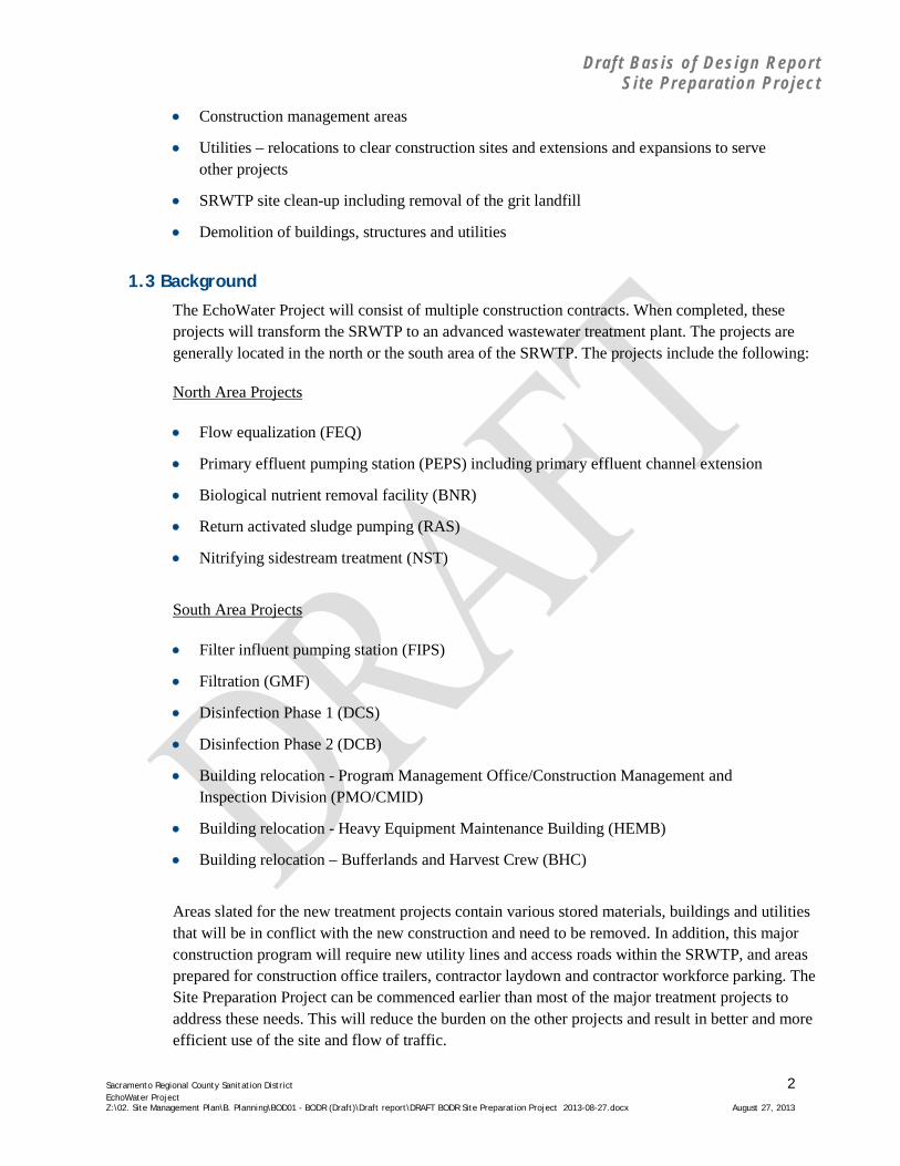
• Construction management areas
• Utilities – relocations to clear construction sites and extensions and expansions to serve other projects
• SRWTP site clean-up including removal of the grit landfill
• Demolition of buildings, structures and utilities
1.3 Background
The EchoWater Project will consist of multiple construction contracts. When completed, these projects will transform the SRWTP to an advanced wastewater treatment plant. The projects are generally located in the north or the south area of the SRWTP. The projects include the following:
North Area Projects
• Flow equalization (FEQ)
• Primary effluent pumping station (PEPS) including primary effluent channel extension
• Biological nutrient removal facility (BNR)
• Return activated sludge pumping (RAS)
• Nitrifying sidestream treatment (NST)
South Area Projects
• Filter influent pumping station (FIPS)
• Filtration (GMF)
• Disinfection Phase 1 (DCS)
• Disinfection Phase 2 (DCB)
• Building relocation - Program Management Office/Construction Management and Inspection Division (PMO/CMID)
• Building relocation - Heavy Equipment Maintenance Building (HEMB)
• Building relocation – Bufferlands and Harvest Crew (BHC)
Areas slated for the new treatment projects contain various stored materials, buildings and utilities that will be in conflict with the new construction and need to be removed. In addition, this major construction program will require new utility lines and access roads within the SRWTP, and areas prepared for construction office trailers, contractor laydown and contractor workforce parking. The Site Preparation Project can be commenced earlier than most of the major treatment projects to address these needs. This will reduce the burden on the other projects and result in better and more efficient use of the site and flow of traffic.
Draft Basis of Design Report Site Preparation Project
Sacramento Regional County Sanitation District 3 EchoWater Project Z:\02. Site Management Plan\B. Planning\BOD01 - BODR (Draft)\Draft report\DRAFT BODR Site Preparation Project 2013-08-27.docx August 27, 2013
The PMO/CMID, Bufferlands, and Harvest Crew buildings will be constructed before the Site Preparation Project commences. Therefore, the site-related needs of these projects cannot be addressed by the Site Preparation Project and are not considered in this BODR. Although the HEMB will be constructed later, it appears logical at this time that utilities for this building will be installed under the Harvest Crew contract because the two buildings share a common site. Thus, utilities for the HEMB will not be considered further in this BODR.
Except as discussed above, none of the projects, including the Site Preparation Project, will begin construction until the environmental impact report (EIR) is certified and subsequently permits are obtained. The environmental permit process is currently scheduled to be completed in the fall of 2014. Refer to the Program Summary Schedule, June 2013 update, attached as Attachment L. The FEQ project is expected to be the first treatment process project to commence construction (scheduled for early-2015), which is concurrent with the Site Preparation Project construction. Contractor facilities for the FEQ will initially be temporary facilities and, after the north area field office complex is complete under the Site Preparation Project, the FEQ contractor will relocate to this location. The BNR project construction will follow in early 2016. The duration of the site preparation construction is estimated to encompass approximately 18 months from January/February 2015 to July 2016. Thus, it will overlap the first year of construction of the FEQ project and the early part of the BNR project. There may be several other EchoWater Projects with concurrent overlapping construction schedules as well.
During design, it will be critical to coordinate with all of the EchoWater Project PMO planning and design teams to ensure that the components of the Site Preparation Project are designed, sequenced and constructed appropriately to meet the program needs.
1.4 Related Technical Memoranda
The following topics are being addressed by other documents:
• Overall Planning of SRWTP for the EchoWater Project Program and Future Expansion - Site Management TM 1 – Facilities Site Planning.
• Master Site Improvements – Site Preparation TM 2 includes construction of north and south contractor and CM field office complexes.
• Wet Utilities – Site Preparation TM 3 addresses new demands and expansion requirements for water systems and sanitary systems.
• Air Systems – Site Preparation TM 4 addresses new demands for air systems.
• Storm Drainage – Site Preparation TM 5 addresses new demands and expansion alternatives for storm drainage.
• Process Piping and Ductbank Relocations – Site Preparation TM 6 addresses the needs for process piping and ductbank relocations and expansions for the north and south project areas.

Draft Basis of Design Report Site Preparation Project
Sacramento Regional County Sanitation District 4 EchoWater Project Z:\02. Site Management Plan\B. Planning\BOD01 - BODR (Draft)\Draft report\DRAFT BODR Site Preparation Project 2013-08-27.docx August 27, 2013
• Plant Communications – Site Preparation TM 7 describes connections of treatment projects to the plant communications systems.
• Site Security – Site Preparation TM 8 summarizes plans for security and management of construction traffic and contractor access to the plant.
• Site Soil Balance – Site Preparation TM 9 summarizes soil balance options for the EchoWater Project. It presents the estimated quantity of excess material and options for offsite disposal and onsite stockpiles.
• Landfill Clean Closure – a separate TM titled Feasibility Assessment for Partial and Total Clean Closure of the Grit and Screenings Landfill presents the initial characterization of the landfill contents, estimated quantity of material to be disposed, and estimated costs.
2.0 Overall EchoWater Project Site Plan
An overall plan of the SRWTP showing the major treatment projects and components of the site preparation is shown on Figures 1 and 2. The major treatment process projects are generally divided into those in the north and south areas of SRWTP. Elements of the Site Preparation Project are described in subsequent sections.
3.0 Construction Workforce and Traffic Projections
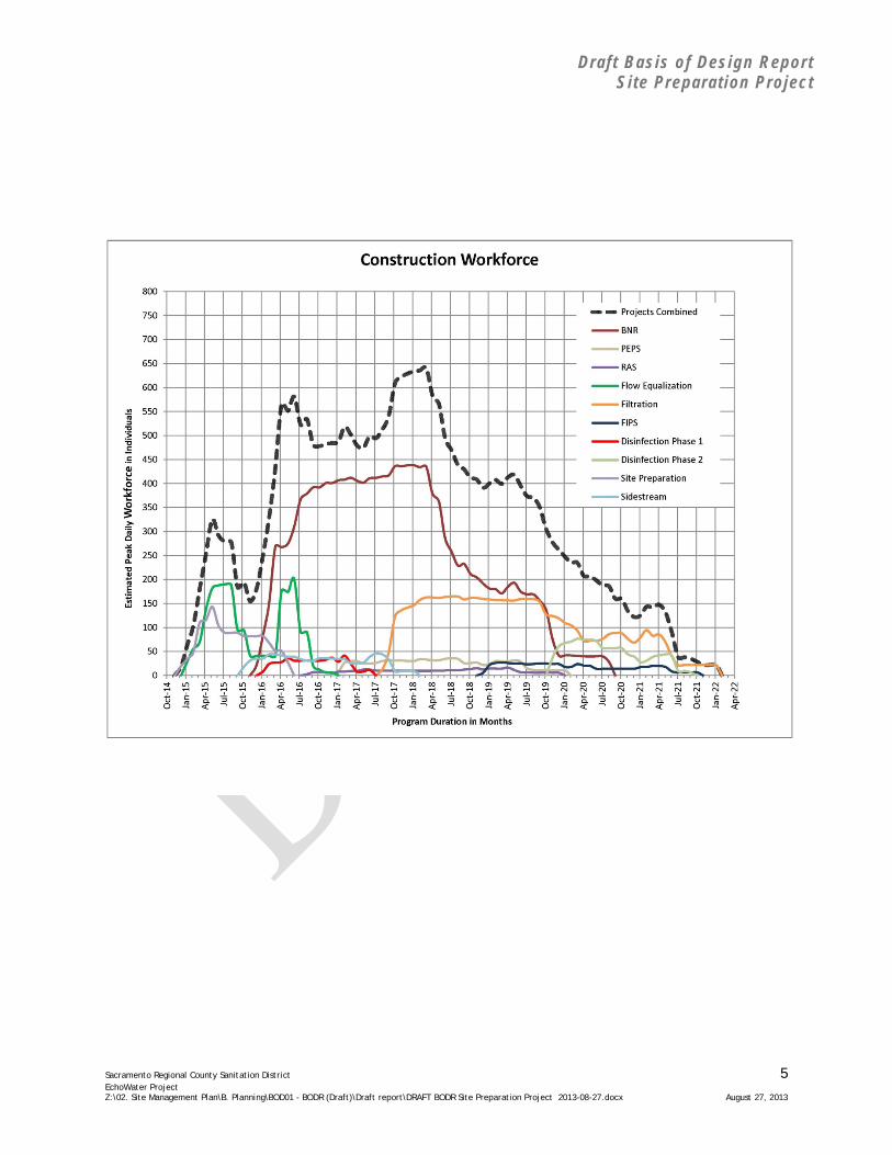
Estimates of the construction workforce and related CM staffing were prepared to evaluate contractor facility needs. These estimates helped determine order-of-magnitude peak traffic counts, area and utility needs for field office trailers, and space requirements/allocations for parking. The contractor workforce was estimated from the construction cost estimates and project schedules current as of April 2013. The methodology is described in detail in TM 2 – Master Site Plan and Improvements (Attachment B); however, note that the basis for the estimates has been updated since TM 2 was prepared. Graph 1 on the following page shows the estimated construction workforce at peak and over time. The maximum number of workers estimated at peak is approximately 650.
To estimate the total construction traffic count, material and equipment deliveries were forecasted for each of the projects and then added to the contractor daily workforce. To be conservative, contractor employees were assumed to drive in single occupancy vehicles and all concrete was based on being delivered from offsite sources. CM staff and Program Management Office (PMO) staff in single occupancy vehicles were added to the total construction traffic count to estimate an overall total construction traffic quantity.
Draft Basis of Design Report Site Preparation Project
Sacramento Regional County Sanitation District 5 EchoWater Project Z:\02. Site Management Plan\B. Planning\BOD01 - BODR (Draft)\Draft report\DRAFT BODR Site Preparation Project 2013-08-27.docx August 27, 2013

Draft Basis of Design Report Site Preparation Project
Sacramento Regional County Sanitation District 6 EchoWater Project Z:\02. Site Management Plan\B. Planning\BOD01 - BODR (Draft)\Draft report\DRAFT BODR Site Preparation Project 2013-08-27.docx August 27, 2013
Graph 2 on the following page depicts the estimated overall daily traffic count and shows an estimated peak of approximately 1400 + trips to the site daily. This count is based on excess soil from the projects is off hauled. This is conservative because there are onsite stockpiling options available for the excess soil. This traffic count does not include traffic associated with regular SRWTP staff and normal operation of SRWTP. The regular SRWTP traffic will continue to use the main access route into SRWTP (Sims Road).
4.0 Construction Gates and Internal Access Roads Improvements
A substantial amount of traffic must to be accommodated during construction. This traffic will pass through the new security gate and require orderly and safe means to reach their destinations.
A new access route into SRWTP will be provided in addition to the existing access from Sims Road and Laguna Station Road. The District is constructing the Dwight Road Extension project that will provide a new access route into the SRWTP from Laguna Boulevard south of the SRWTP property. Under the Site Preparation Project, a new security gate will be built at the northern end of the Dwight Road extension and, from there, internal access roads will be improved to accommodate construction-related traffic and future plant deliveries. This will be the primary access route into SRWTP for all construction traffic for the EchoWater Project.
The sources of traffic include:
• Contractor and CM workforce and visitors
• Construction traffic (concrete transit trucks, water trucks, excess soil and waste hauling)
• Construction deliveries (materials and equipment)
• CMID, design engineers and PMO staff (to/from workplace)
• Users of the fueling station at the existing HEMB (may continue use of main entrance during construction but will share internal access roads)
• Plant Operations and Maintenance - in-plant traffic and delivery of equipment and supplies (will continue to use main entrance during construction but will share internal access roads)
• Septage and fats/oils/grease (FOG) deliveries (may continue to use main entrance during construction but will share internal access roads)
• Visitors to SRWTP for EchoWater Project
• Biosolids Recycling Facility (BRF) traffic (may use new Dwight Road but will have through access outside security gate)
• Carson Energy/Glacier Ice Plant traffic (may use new Dwight Road but will have through access outside security gate)
SRWTP employees, BRF and Carson Energy/Ice Plant traffic, and traffic related to normal operation of the plant will continue to use Sims Road, Laguna Station Road and the existing security gate near the Administration Building.

Draft Basis of Design Report Site Preparation Project
Sacramento Regional County Sanitation District 7 EchoWater Project Z:\02. Site Management Plan\B. Planning\BOD01 - BODR (Draft)\Draft report\DRAFT BODR Site Preparation Project 2013-08-27.docx August 27, 2013
Draft Basis of Design Report Site Preparation Project
Sacramento Regional County Sanitation District 8 EchoWater Project Z:\02. Site Management Plan\B. Planning\BOD01 - BODR (Draft)\Draft report\DRAFT BODR Site Preparation Project 2013-08-27.docx August 27, 2013
Figures 3 through 8 show the locations of the new site access improvements. These items are described in more detail below. Note that areas proposed for AC and gravel will need to be coordinated with the other projects and likely will change from what is shown.
4.1 Dwight Road Security Guard Facility
The new security guard facility will be located at the north end of the Dwight Road extension and will be the primary access point for contractors and construction-related traffic. The preliminary location and configuration of the security gates are shown on Figure 8.
The security guard facility will have a building for security staff with lighting, heating and air conditioning, and a restroom. There will also be security cameras installed at the facility. Three ingress and three egress lanes are estimated to be required to handle traffic demands. Each lane will have an automated gate access entry. This will either be a badge system or vehicle placard (fast pass type system).
The electrical power for the security guard facility will be fed from a new substation installed by the PMO/CMID building project (to the north of the security guard facility – shown on Figure 1). This will be an outdoor NEMA3R double-ended substation arrangement, two 12kV fused switches dual 500kVA 12kV-480V transformers with two mains and automatic tie breaker with distribution breakers to feed the security guard facility and the Bufferlands building. This substation will be in place prior to the site preparation project. However, the site preparation project will extend the 12kV ductbank along Landfill Way to the east and also install new 12kV manholes near the PMO building along with the ductbanks and cabling required for the security guard facility. The new Security Facility will require fiber optic cable to support MIS, Maintenance, CCTV, and Public Address networks (for internet, telephone, public address, security and other systems). Spare conduits shall be available for fiber from the Oxygen Plant Main Fiber Optic termination panel to the intersection of Central St and Landfill Way in an existing ductbank and the Tertiary Site relocated ductbank. A signal ductbank shall be installed from this intersection to the Security Facility.
Layout and sizing of the security guard facility including number and size of traffic lanes will be required to ensure adequate room for truck traffic, contractor workforce (at peak) and adequate space for emergency vehicles (fire, etc.). Options for contractor and vehicle badging will also need to be evaluated and designed.
Construction of the security gate must be an early completion item to minimize the time that the FEQ contractor is using a temporary construction access gate or entering through the main SRWTP entrance gate.
4.2 Alternative Construction Access Gate
The original construction entrance on Sims Road west of Laguna Station Road will be refurbished for use as a second construction access gate to be used prior to completion of the permanent gate on Dwight Road. This second gate will also serve as a dual-entrance “strike gate” during construction and a temporary gate during periods of significant truck traffic, such as disposal of excess soil from
Draft Basis of Design Report Site Preparation Project
Sacramento Regional County Sanitation District 9 EchoWater Project Z:\02. Site Management Plan\B. Planning\BOD01 - BODR (Draft)\Draft report\DRAFT BODR Site Preparation Project 2013-08-27.docx August 27, 2013
excavation or major deliveries of material or equipment. This work includes improvements to the existing guard shelter at Sims Road, connection to the new Dwight Road extension, lighting, communications, signage and fencing.
4.3 Internal Access Roads
A two-way, two-lane internal access road (potentially three lanes in some areas of heavy traffic) will be constructed from the Dwight Road security gate to the north and south area project sites. Each lane will be approximately 16 feet wide. Refer to Figures 3 through 7 for additional details and proposed sections. Site preparation designer will need to design roadway sections, fill, grading and drainage requirements.
There are portions of the access road which will be asphalt concrete (AC) with reinforced concrete sections for heavy equipment crossings, and other portions which will be gravel sections. The portion of the access road aligned along Landfill Way will need to be located temporarily a distance south of Landfill Way (on the order of 100 to 150 feet) to allow for utility relocation and reconstruction of the permanent road (see Figure 4).
Sims Road west of the secondary sedimentation tanks (SSTs) will be reserved as an alternative access for construction traffic. In addition, a construction equipment corridor will be reserved to the west of Sims Road for use by heavy construction traffic such as scrapers or earth-hauling trucks.
In addition to access for construction traffic, the internal access road improvements will provide access for septage and FOG haulers to the northeast area of SRWTP where the septage and FOG receiving facilities are located. There will be alternate routes to the north and south of the BNR project to provide continuous access to the septage and FOG receiving facilities during construction of the FEQ, BNR and PEPS projects.
Access roads to the septage and FOG receiving facilities in the vicinity of the BNR, FEQ and PEPS projects are expected to require local adjustments in alignment during construction, so these portions of the roads may be constructed initially using aggregate base. The timing of permanent paving of the access roads may be such that it cannot be part of the Site Preparation Project. That work might best fit with the FEQ or BNR projects.
Security fencing will be modified along the construction access roads. The existing security fencings around the process area must be relocated. Prior to demolishing the existing fence, the new fence shall be installed. It must include personnel and vehicle gates. Refer to Figure 7 for additional details.
5.0 Contractor Facilities
Contractor facilities consist of areas prepared for contractor and CM office trailers, contractor laydown and contractor employee parking. The locations of the north and south contractor laydown and office complex sites are shown on Figure 1.

Draft Basis of Design Report Site Preparation Project
Sacramento Regional County Sanitation District 10 EchoWater Project Z:\02. Site Management Plan\B. Planning\BOD01 - BODR (Draft)\Draft report\DRAFT BODR Site Preparation Project 2013-08-27.docx August 27, 2013
5.1 Estimated Area Needs for Contractor Facilities
In the north and south areas, the CM and contractor field offices for the various projects will be located adjacent to each other, forming a field office complex. Sufficient space will be allocated to accommodate the field offices and associated parking and staging areas. In addition, since the field office complex will be located in close proximity to the work, the area will include space to support short-term storage of materials, delivery truck queue, concrete truck queue and staging of some materials and equipment from the storage/laydown area.
The space allocation for the entire field office complex was determined by multiplying the peak field staff levels (CM and contractor) by 2,000 square feet per field office staff member, which includes gross area for trailers, decking and access, parking for field office staff and visitors, and short-term construction traffic queues. The 2,000 square feet per staff member multiplier was determined from review of previous projects of similar size and type of construction and will need to be confirmed and verified.
Areas for contractor workforce parking are based on the peak construction workforce estimates from the April 2013 PMO schedule and construction estimate updates from April 2013. Note that these estimates do generate a more conservative forecast because each of the individual project peaks will not actually be concurrent. The following assumptions were used to estimate the contractor construction parking areas:
• Peak workforce estimate includes field office staff, subcontractors and visitors associated with the project
• No carpooling or ride sharing of workers
• Parking area per worker estimated at 320 square feet, which includes allowance for common driveways and through lanes.
Adequate laydown, storage and staging areas are required for each of the construction projects. In both the north and south areas, a staging/laydown area has been allocated for each project. Refer to Figures 9 and 10. The size allocation is based upon previous projects of similar size and scope as well as availability to onsite areas in these locations. In addition, smaller laydown areas adjacent to the PEPS and RAS projects have been reserved along with additional contractor parking south of the north contractor area. Refer to Figure 1.
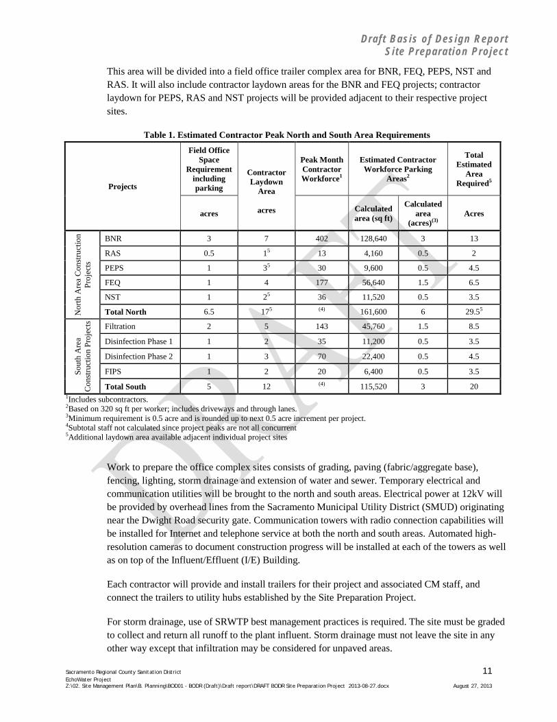
Table 1 summarizes the estimated area needs for contractor/CM office trailers, workforce parking and laydown. More detail about the derivation of these quantities may be found in TM 2 Master Site Plan and Improvements (Attachment B). These estimates should be re-evaluated/confirmed by the design consultant.
5.2 Contractor/CM Field Office Complex (North Area)
The north area complex will serve the BNR, FEQ, PEPS, RAS, and NST projects. The location is south of Emergency Storage Basin (ESB) C covering approximately 21 acres north of ESB-D Road. A preliminary layout of the north area is shown on Figure 9.
Draft Basis of Design Report Site Preparation Project
Sacramento Regional County Sanitation District 11 EchoWater Project Z:\02. Site Management Plan\B. Planning\BOD01 - BODR (Draft)\Draft report\DRAFT BODR Site Preparation Project 2013-08-27.docx August 27, 2013
This area will be divided into a field office trailer complex area for BNR, FEQ, PEPS, NST and RAS. It will also include contractor laydown areas for the BNR and FEQ projects; contractor laydown for PEPS, RAS and NST projects will be provided adjacent to their respective project sites.
Table 1. Estimated Contractor Peak North and South Area Requirements
Projects
Field Office Space
Requirement including parking
Contractor Laydown
Area
acres
Peak Month Contractor Workforce1
Estimated Contractor Workforce Parking
Areas2
Total Estimated
Area Required5
acres Calculated area (sq ft)
Calculated area
(acres)(3) Acres
Nor
th A
rea
Con
stru
ctio
n Pr
ojec
ts
BNR 3 7 402 128,640 3 13
RAS 0.5 15 13 4,160 0.5 2
PEPS 1 35 30 9,600 0.5 4.5
FEQ 1 4 177 56,640 1.5 6.5
NST 1 25 36 11,520 0.5 3.5
Total North 6.5 175 (4) 161,600 6 29.55
Sout
h A
rea
Con
stru
ctio
n Pr
ojec
ts
Filtration 2 5 143 45,760 1.5 8.5
Disinfection Phase 1 1 2 35 11,200 0.5 3.5
Disinfection Phase 2 1 3 70 22,400 0.5 4.5
FIPS 1 2 20 6,400 0.5 3.5
Total South 5 12 (4) 115,520 3 20 1Includes subcontractors. 2Based on 320 sq ft per worker; includes driveways and through lanes. 3Minimum requirement is 0.5 acre and is rounded up to next 0.5 acre increment per project. 4Subtotal staff not calculated since project peaks are not all concurrent 5Additional laydown area available adjacent individual project sites
Work to prepare the office complex sites consists of grading, paving (fabric/aggregate base), fencing, lighting, storm drainage and extension of water and sewer. Temporary electrical and communication utilities will be brought to the north and south areas. Electrical power at 12kV will be provided by overhead lines from the Sacramento Municipal Utility District (SMUD) originating near the Dwight Road security gate. Communication towers with radio connection capabilities will be installed for Internet and telephone service at both the north and south areas. Automated high-resolution cameras to document construction progress will be installed at each of the towers as well as on top of the Influent/Effluent (I/E) Building.
Each contractor will provide and install trailers for their project and associated CM staff, and connect the trailers to utility hubs established by the Site Preparation Project.
For storm drainage, use of SRWTP best management practices is required. The site must be graded to collect and return all runoff to the plant influent. Storm drainage must not leave the site in any other way except that infiltration may be considered for unpaved areas.
Draft Basis of Design Report Site Preparation Project
Sacramento Regional County Sanitation District 12 EchoWater Project Z:\02. Site Management Plan\B. Planning\BOD01 - BODR (Draft)\Draft report\DRAFT BODR Site Preparation Project 2013-08-27.docx August 27, 2013
Contractor laydown will be left for the individual contractors to develop and manage as they prefer. Each process project contract will indicate the area available to that project’s contractor.
5.3 Contractor/CM Field Office Complex (South Area)
The south area complex will serve the GMF, DCS, DCB, and FIPS projects. The recommended location for the south area complex is south of Landfill Way opposite the existing grit landfill. The area for the complex is approximately 25 acres in size. A preliminary layout of the south area is shown on Figure 10.
This location is currently being evaluated in the environmental review process due to the presence of wetlands and vernal pools. However, this area is proposed for future solids storage basins (SSBs); therefore, it is anticipated that this area will be available for contractor use in the interim.
Work to prepare the south office complex site is as generally described above for the north area. Each contractor will provide and install trailers for their project and associated CM staff, and connect the trailers to utility hubs. Pumping of wastewater is likely to be necessary to reach the plant collection system (sanitary drain) on the other side of Landfill Way.
For storm drainage, use of SRWTP best management practices is required. The site must be graded to direct all runoff to the north for collection and return to the plant influent. Storm drainage must not leave the site in any other way except that infiltration may be considered for unpaved areas. Pumping may be required to convey collected storm drainage to the plant collection system across Landfill Way.
5.3.1 Contractor Employee Parking
Parking areas will be constructed adjacent to the north and south contractor and CM field office complexes. Additional north area contractor parking will be provided on approximately 3.5 acres south of ESB-D Way and directly east of the concrete batch plant site. In the south area, all contractor employee parking will be located adjacent to the trailers.
6.0 Temporary Construction Utilities
Utilities will be extended from existing SRWTP systems to support construction-related demands except for electrical and communications which will be outside temporary services. The utility demands include the north and south field office complexes and the estimated construction demands for individual projects. The utilities serving the north and south field office complexes will be terminated in a manner that allows individual contractors to access and connect their office trailers and associated CM staff trailers to utility hubs. Construction-related utility demands and likely points of service connection are described below.
6.1 Temporary Construction Utility Demands
The utility demands for the north and south field office complexes were estimated using trailer size and estimated number of occupants.
Draft Basis of Design Report Site Preparation Project
Sacramento Regional County Sanitation District 13 EchoWater Project Z:\02. Site Management Plan\B. Planning\BOD01 - BODR (Draft)\Draft report\DRAFT BODR Site Preparation Project 2013-08-27.docx August 27, 2013
6.1.1 Water and Sewer Demands
For potable water, a nominal 2 gpm per trailer section was used to calculate a conservative demand. For sanitary sewer, a conservative nominal 4-inch sewer lateral is required per complete trailer unit; i.e., one per triple- or double-wide trailer. For fire protection, fire hydrants are planned because the largest single trailer is a triple wide (36 feet x 60 feet) and is below the 3,000-square-foot threshold requirement for fire sprinklers.
However, if fire sprinklers are required by the fire marshal, the assumed demand is 0.1 gpm/sf for the first 1,500 square feet of building area, plus another 100 gpm available at a connection outside the building, for a total of 250 gpm. To be conservative at this early stage, it is assumed fire sprinklers would also be required.
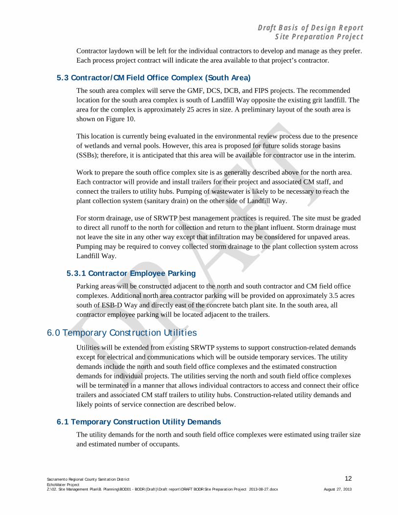
Table 2 summarizes the water and sanitary demands for both the north and south field office complexes.
Table 2. Water and Sanitary Sewer Demand for North and South Area Trailer Complexes
Projects Potable Water Demand - Trailer
Complex Sanitary
Demand - Trailer
Unit
Fire Protection - Trailer Complex
Trailer Sections Demand gal/min
North Area Construction
Projects
BNR 16 36 4" lateral
250 gpm sprinkler demand plus 2,000 gpm
hydrant demand
RAS 4 12 4" lateral
PEPS 6 16 4" lateral FEQ 8 16 4" lateral NST 7 16 4" lateral Total North 41 96
South Area Construction
Projects
Filtration 13 32 4" lateral
250 gpm sprinkler demand plus 2,000 gpm
hydrant demand
Disinfection Phase 1 5 20 4" lateral Disinfection Phase 2 6 12 4" lateral FIPS 5 16 4" lateral Total South 29 68 4" lateral
Construction water demands are difficult to quantify, but will be substantial at times both in the north and south construction areas. Multiple points of connection for construction water are identified in Section 8.5 and shown on Figures 9 and 10.
6.1.2 Electrical, Internet and Telephone Demands
Initial electrical demand estimates were based on typical electrical service panels provided for each trailer section and a demand factor of 50 percent. Each trailer section has a 120VAC/125 amp panel; the air conditioning/heating unit can also be run from 240 VAC power. Each section was assumed to have a connected load of 125 amps at 120VAC and a demand factor of 50 percent.
The recommended source of electrical power is to route an overhead 12kV power line directly from SMUD as shown on Figure 3. The point of connection with SMUD will be an existing pole located south of Glacier Way. The pole line will parallel the new access road along Landfill Way and SSB-1 Road westward to SSB Battery I and then north to the North Contractor/CM Trailer Area. SMUD would design the overhead power line. This approach will ensure that the construction power is kept separate from the plant process power (a preference by District Operations and
Draft Basis of Design Report Site Preparation Project
Sacramento Regional County Sanitation District 14 EchoWater Project Z:\02. Site Management Plan\B. Planning\BOD01 - BODR (Draft)\Draft report\DRAFT BODR Site Preparation Project 2013-08-27.docx August 27, 2013
Maintenance) and will not require dual feeds to maintain continuous power. The District is working in parallel with SMUD to initiate an application for this service.
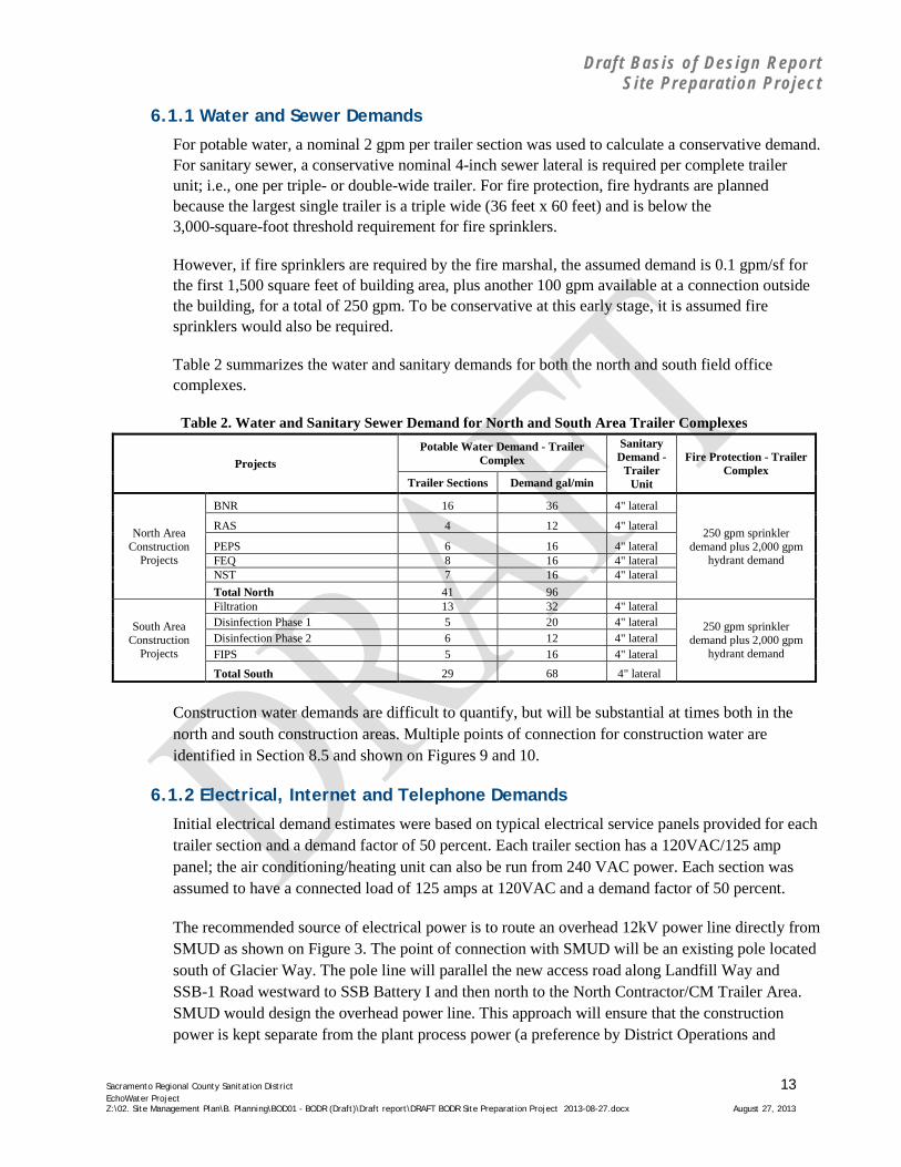
Internet service will be extended from the County system via radio towers at the north and south areas. The radio towers will be capable to support internet and telephone service through VOIP. Internet demands are expected to be large due to the number of users, anticipated use of PMWeb for sharing and transfer of large files, and the use of building information modeling (BIM) for design and construction drawings.
Table 3. Electrical, Telephone and Internet Demand for North and South Area Trailer Complexes
Projects
Electrical - Demand Electrical Demand
KVA
Communications Demand - Internet & Telephone - Trailer Complex
Trailer Sections
Connected panels in amps
@ 120 VAC
Based on 50% Demand Amps
@ 120 VAC
CM Trailers Phone and Internet
Contractor Trailers Phone and Internet
Nor
th A
rea
Con
stru
ctio
n Pr
ojec
ts
BNR 16 2000 1000 120
Dedicated Internet service via Radio
Tower, 800MB with connection to the
County system and VOIP telephone
Dedicated Internet service via Radio
Tower, 800 MB with wireless VPN
connection and ability to connect VOIP
telephone
RAS 4 500 250 30
PEPS 6 750 375 45
FEQ 8 1000 500 60
NST 7 875 437 52
Total North 41 4125 3000 307
Sout
h A
rea
Con
stru
ctio
n Pr
ojec
ts
Filtration 13 1625 812 97 Dedicated Internet service via Radio
Tower , 800 MB with connection to the
County system and VOIP telephone
Dedicated Internet service via Radio
Tower, 800 MB with wireless VPN
connection and ability to connect VOIP
telephone
Disinfection Ph 1 5 625 312 37
Disinfection Ph 2 6 750 375 45
FIPS 5 625 312 37
Total South 29 3625 1812 217
6.2 North Area Construction Utilities – Points of Connection and Supply
Existing plant utility data was collected to determine potential and reasonable points of connection for each of the utilities required for the north area trailer complex and the north area construction projects. Proposed utility services for this area are described below and most are illustrated on Figure 9. This figure also shows the proposed location for the trailers, parking and lay down areas. Alternative points of connection were evaluated in TM 2. The recommended points of connection are provided below.
6.2.1 Potable Water (WP) - North
Potable water is delivered to the north side of SRWTP by a 14-inch line from the City of Sacramento. WP is distributed around the plant from a booster pumping station in the I/E Building. The recommended means to supply WP to the north construction trailer area is to extend an existing 4-inch WP from the west end of the central tunnel. However, the location and routing will need to
Draft Basis of Design Report Site Preparation Project
Sacramento Regional County Sanitation District 15 EchoWater Project Z:\02. Site Management Plan\B. Planning\BOD01 - BODR (Draft)\Draft report\DRAFT BODR Site Preparation Project 2013-08-27.docx August 27, 2013
be coordinated with the BNR project to avoid a future conflict in this general vicinity. Work will include core-drilling a hole in the tunnel wall and installing a backflow prevention device.
6.2.2 Fire Suppression (WN, WRH) - North
Fire suppression water is recommended to be supplied from two sources. For building sprinklers, the recommended source is a 4-inch WN line that traverses the south side of the site. This line serves the ESB-D pumping station from the central tunnel. Demands at ESB-D are relatively minor and include pump seal water and utility stations. Based on a preliminary check, this line should have capacity to supply the north field office complex sprinkler demand of 250 gpm. If the capacity is inadequate, the source line in the central tunnel is a 6-inch line and the 4-inch line either could be increased in size or paralleled.
For fire hydrant supply, connection to the 6-inch WRH on the west side of the site is recommended. A new 18-inch WRH line is planned along the south and west sides of the north office trailer and contractor laydown site as part of a loop to supply washdown hydrants for the ESBs. This line will be constructed by the site preparation contractor and may be an option for fire hydrants.
6.2.3 Sanitary Drainage (SD) - North
There is a 36-inch supernatant (SN) line running adjacent to ESB-D that could serve the trailer complex. There are manholes at both the north and south ends of the site.
6.2.4 Storm Drainage (STD) – North
There is a 36-inch STD line which runs along the south side of ESB-C with accessible manholes. This connection could serve the contractor laydown portion of the construction site. The north field office complex is at a significant distance away from the 36-inch STD and could be served more directly by routing drainage to the 36-inch SN line as is proposed for sanitary drainage.
6.2.5 Electrical Power - North
The Site Preparation Project will include an outdoor 12kV switch and a 12kV/480V transformer to step down voltage from the SMUD overhead 12kV line. Based upon the estimated demands for the North Contractor/CM trailer complex, a 500KVA transformer is proposed with an additional 500KVA transformer for temporary construction power. Power distribution from the transformers shall be metered at the 480VAC level, provided, installed and distributed by the process project contractors as appropriate. Temporary 480VAC power distribution lines at a minimum shall be direct buried 24 inches from top of grade. An additional 750-kvA transformer and power drop from the overhead SMUD line will also be provided at the concrete batch plant.
6.2.6 Communications (Telephone and Internet) - North
The Site Preparation Project will install a temporary radio tower facility to provide internet connection for the field office complex. This will include a monopole tower and enclosure at the base of the tower. The monopole will provide mounting and support of licensed, wireless backhaul traffic to the District’s PCC/IE Building. The height of the tower is to be determined for each location, but shall provide a 20-foot minimum clear path looking back to the PCC/IE building. The

Draft Basis of Design Report Site Preparation Project
Sacramento Regional County Sanitation District 16 EchoWater Project Z:\02. Site Management Plan\B. Planning\BOD01 - BODR (Draft)\Draft report\DRAFT BODR Site Preparation Project 2013-08-27.docx August 27, 2013
monopole will have a fixed ladder or other external method of climbing that is Cal-OSHA approved. The monopole will have mounting hardware including accommodation of up to 3-inch pipe mount antenna masts.
The monopole tower shall have a climate-controlled enclosure near its base. The enclosure will be a cell site type container, with penetrations and overhead ladder racks to accommodate fiber, power and copper cabling. The enclosure shall offer all power necessary for climate control and network device support to include six NEMA 5-20 circuits. The enclosure shall be outfitted with two 19-inch network racks for switching gear, UPS and extended runtime batteries.
The radio tower site for the north will be connected to the main SRCSD building by 800MB radio connectivity. The individual process projects will install their own direct fiber or Ethernet connections to the enclosure. Each trailer will have a 24-port gig switch which will provide connectivity to both OpenNet (District’s wireless Internet connection) and to the County server access. Each trailer will have a wireless access point. The County standard is Meraki. Each trailer will have no less than 10 hard-wired connections which will accommodate the need for both OpenNet and County server access.
Construction management trailers will have VOIP phones provided by the County. This may require POE switches to accommodate the phones. Phones should have built-in switches to allow hardwire connection of desktops/laptops. Contractor trailers will have the ability to provide their own VOIP solution.
6.2.7 Construction Water - North
Construction water will be needed for earthwork and hydrostatic testing of structures. Periodically, the demand will be significant, such as when subgrade is being prepared in the BNR structure, the ESB-C cross levees are being constructed, and the BNR basins, PEPS and primary effluent channel extension are being tested for leaks. Secondary effluent (WRL, WRH) would be suitable for earthwork and dust control, but cleaner water would be preferred for hydrostatic testing and equipment washdown. Construction water will be needed for the concrete batch plant if the option to construct this facility is exercised by the FEQ contractor.
The north area projects cover a large area and multiple options for construction water are recommended. In each case, the recommended approach is to identify one or more options in each project’s contract documents and then have the contractor construct the appropriate connections and filling stations. Recommended options include:
• 8-inch WRH – This line currently supplies a fire hydrant at the PMO/CMID building and would be a source of construction water for the PEPS and BNR projects.
• 10-inch WRH – This line runs north-south on the west side of the SSTs. It could be tapped at its northern end for the BNR and FEQ projects.
• 6-inch WRH – This line runs north-south on the east side of SSB Battery I and could supply water to the NST project.
Draft Basis of Design Report Site Preparation Project
Sacramento Regional County Sanitation District 17 EchoWater Project Z:\02. Site Management Plan\B. Planning\BOD01 - BODR (Draft)\Draft report\DRAFT BODR Site Preparation Project 2013-08-27.docx August 27, 2013
• New 18-inch WRH – A new 18-inch line will be constructed by the Site Preparation Project. Refer to Section 7.5 for more detail. This new pipeline could have outlets for construction water. The number and location of such outlets would be determined by the Site Preparation Project designer in coordination with other project designers.
• Existing well and truck filling facility – This well is adjacent to SSB Battery I and is used primarily for filling water trucks for dust control. It has a capacity of approximately 1,100 gpm. BNR and FEQ project contractors could fill trucks at this site, but it might be more cost-effective to extend a line from the well to the BNR and FEQ project sites, a distance of about 1,500 feet. This option can be assessed by BNR and FEQ project designers. This well is the planned source of water for a possible concrete batch plant that could share the pipeline extension.
• New well – A new well could be constructed in the future BNR footprint to serve the BNR and FEQ basin projects.
• The District’s SE water may also be a source for construction water.
6.3 South Area Construction Utilities – Points of Connection and Supply
Existing plant utility data was collected to determine potential and reasonable points of connection for each of the utilities required for the south field office complex and the south area construction projects. Proposed utility services for this area are described below and are illustrated on Figure 10. Alternative points of connection were evaluated in TM 2 - Master Site Plan and Improvements. The recommended points of connection are provided below.
6.3.1 Potable Water (WP) - South
Potable water is distributed to the south area of SRWTP from the WP booster station in the I/E Building; however, the WP lines do not extend into the area of the south construction trailer complex. A second source of WP at the SRWTP is a 16-inch WP line from the Sacramento County Water Agency (SCWA) that is located on the east side of the landfill on Central Street. This line serves the Glacier Ice Plant, Biosolids Recycling Facility (BRF) and the Water Reclamation Facility (WRF). This 16-inch line is the recommended source of WP for the south construction trailers. There is an existing 6-inch tee which could be used as a connection to this line at the southeast corner of the landfill on Central Street to provide potable water as well as provide an optional source of fire protection water for fire hydrants and building fire sprinklers. A flow meter (for SCWA billing) and an air gap would be required to serve all south area WP needs. The relocated PMO/CMID and Bufferlands buildings will be connecting to this 16-inch line and service connection will need to be coordinated.
6.3.2 Fire Suppression (Hydrants) - South
The recommended source of fire hydrant supply is the new 10-inch WRH loop to be constructed by the site preparation contract (refer to Section 7.5).
Draft Basis of Design Report Site Preparation Project
Sacramento Regional County Sanitation District 18 EchoWater Project Z:\02. Site Management Plan\B. Planning\BOD01 - BODR (Draft)\Draft report\DRAFT BODR Site Preparation Project 2013-08-27.docx August 27, 2013
6.3.3 Sanitary Drainage (SD) - South
The recommended point of connection is a 12-inch SD line at the old Bufferlands trailer site (new PMO/CMID and Bufferlands buildings site) located north across Landfill Way. There are a number of existing utilities to cross to get to this location, so it is likely that the wastewater would need to be pumped.
Alternatively, the construction trailers could have temporary storage tanks for sanitary drainage.
6.3.4 Storm Drainage (STD) - South
There is an existing drainage channel on Central Street to the east of the site which runs north and ties into a 12-inch STD line. The site will need to be graded to the northeast to utilize this connection.
6.3.5 Electrical Power - South
The south office trailer complex will be served from the extension of the SMUD overhead 12kV power line located at the corner of Glacier Way and Laguna Station Road.
The Site Preparation Project will include an outdoor 12kV switch and a 12kV/480V transformer to step down voltage from the SMUD overhead 12kV. Based upon the estimated demands for the South Contractor/CM trailer complex, a 500KVA transformer is proposed with an additional 300KVA transformer for temporary construction power. Power distribution from the transformers shall be metered at the 480VAC level, provided, installed and distributed by the process project contractors as appropriate. Temporary 480VAC power distribution lines at a minimum shall be direct buried 24 inches from top of grade.
6.3.6 Communications (Telephone and Internet) - South
The Site Preparation Project will install a temporary radio tower facility to provide internet connection for the field office complex. This will include a monopole tower and enclosure at the base of the tower. The monopole will provide mounting and support of licensed, wireless backhaul traffic to the District’s PCC/IE Building. The height of the tower is to be determined for each location, but shall provide a 20-foot minimum clear path looking back to the PCC/IE building. The monopole will have a fixed ladder or other external method of climbing that is Cal-OSHA approved. The monopole will have mounting hardware including accommodation of up to 3-inch pipe mount antenna masts.
The monopole tower shall have a climate-controlled enclosure near its base. The enclosure will be a cell site type container, with penetrations and overhead ladder racks to accommodate fiber, power and copper cabling. The enclosure shall offer all power necessary for climate control and network device support to include six NEMA 5-20 circuits. The enclosure shall be outfitted with two 19-inch network racks for switching gear, UPS and extended runtime batteries.
The radio tower site for the north will be connected to the main SRCSD building by 800MB radio connectivity. The individual process projects will install their own direct fiber or Ethernet connections to the enclosure. Each trailer will have a 24-port gig switch which will provide

Draft Basis of Design Report Site Preparation Project
Sacramento Regional County Sanitation District 19 EchoWater Project Z:\02. Site Management Plan\B. Planning\BOD01 - BODR (Draft)\Draft report\DRAFT BODR Site Preparation Project 2013-08-27.docx August 27, 2013
connectivity to both OpenNet (District’s wireless Internet connection) and to the County server access. Each trailer will have a wireless access point. The County standard is Meraki. Each trailer will have no less than 10 hard-wired connections which will accommodate the need for both OpenNet and County server access.
Construction management trailers will have VOIP phones provided by the County. This may require POE switches to accommodate the phones. Phones should have built-in switches to allow hardwire connection of desktops/laptops. Contractor trailers will have the ability to provide their own VOIP solution.
6.3.7 Construction Water - South
Multiple options for construction water are recommended. In each case, the recommended approach is to identify one or more options in each project’s contract documents and then have the contractor construct the appropriate connections and filling stations. Recommended options include:
• New 10-inch WRH – This new loop around the tertiary treatment site will be constructed by the site preparation contract and could have outlets provided for construction water.
• Outlets from WRF tank – There are two buried outlets from the WRF storage tank that could be modified to supply construction water. One is a 30-inch outlet from the booster pump suction line and the other is a 16-inch WFP outlet directly from the tank.
• 24-inch WRF – A 10-inch buried outlet from this line is located at the southeast corner of the landfill (Central Street and Landfill Way) and could be modified to supply construction water.
• Fire hydrants – There are several fire hydrants in the area, notably along the secondary effluent channel and near the HEMB that could be used.
• The District’s SE water may also be a source for construction water.
7.0 Permanent Utilities for New Process Projects
Each of the new treatment process projects requires various types of utility services. The types of utilities include:
• Fire suppression
• Potable water (WP)
• Non-potable water (WN)
• Reclaimed water low pressure (WRL) - currently chlorinated secondary effluent
• Reclaimed water high pressure (WRH) - currently chlorinated secondary effluent
• Storm drainage
• Sanitary drainage (SD)

Draft Basis of Design Report Site Preparation Project
Sacramento Regional County Sanitation District 20 EchoWater Project Z:\02. Site Management Plan\B. Planning\BOD01 - BODR (Draft)\Draft report\DRAFT BODR Site Preparation Project 2013-08-27.docx August 27, 2013
• Process drainage (drain (D), tank drain (TD))
• Air systems
Utility services for permanent facilities were analyzed in TM 3 Wet Utilities and TM 4 Air Systems. For many of the plant utilities, service to various EchoWater projects was found best to be provided under the individual projects rather than the Site Preparation Project. Utility extensions and modifications that are proposed as part of site preparation are described below.
7.1 Fire Suppression
Fire flows for hydrant and sprinkler demands are based on the size of the building and type of construction. Permanent buildings at SRWTP are generally constructed of concrete and steel (with few exceptions). This generally allows for lower fire hydrant and sprinkler demands.
Based on anticipated construction materials, fire flow requirements were obtained from the SRWTP Operator’s Manual and the California Fire Code (CFC). Flows for this BODR are based on the higher value from these sources until final requirements are negotiated with the Consumes Community Services District Fire Department. Table 4 summarizes preliminary fire flow requirements. Fire hydrant flows will be provided by the WRH system as described in Section 7.5 whilst fire sprinkler flows will be provided by WN (preferred) or WRH where available. More information on fire flows is in TM 3 - Wet Utilities (Attachment D).
Table 4. Preliminary Fire Protection Flows for New Facilities(1)
Area
Estimated Fire
Hydrants Required
Fire Hydrant
Flow, gpm(2)
Fire Sprinkler Demand,
gpm North Area
BNR- blower building 3 2,000 -- BNR None -- None BNR - secondary treatment control building (ACC) 1 2,000 535
PEPS 1 2,000 None FEQ None -- None NST 1 2,000 --
RAS pumping – ACC 4 office space None -- 535 North construction trailers (temporary) 2 2,000 250(3)
South Area FIPS 1 2,000 535 Filtration area – general 2 2,000 -- Filtration area - tertiary treatment control building (ACC) 1 2,000 535
Disinfection 1 2,000 None South construction trailers (temporary) 2 2,000 250(3) 1. See Appendix A of TM 3 for derivation of the fire hydrant and sprinkler flows based on each
facility’s anticipated size and construction and the CFC. 2. SRWTP fire hydrant flow is used in lieu of CFC’s flow requirement of 1,500 gpm because it is
more conservative. Minimum SRWTP fire hydrant pressure is 25 psi. 3. Temporary construction trailers may not need fire sprinklers. Final demands will be determined
during negotiations with the fire marshal.
Draft Basis of Design Report Site Preparation Project
Sacramento Regional County Sanitation District 21 EchoWater Project Z:\02. Site Management Plan\B. Planning\BOD01 - BODR (Draft)\Draft report\DRAFT BODR Site Preparation Project 2013-08-27.docx August 27, 2013
7.2 Potable Water (WP)
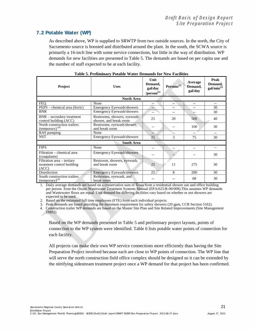
As described above, WP is supplied to SRWTP from two outside sources. In the north, the City of Sacramento source is boosted and distributed around the plant. In the south, the SCWA source is primarily a 16-inch line with some service connections, but little in the way of distribution. WP demands for new facilities are presented in Table 5. The demands are based on per capita use and the number of staff expected to be at each facility.
Table 5. Preliminary Potable Water Demands for New Facilities
Project Uses
Unit Demand, gal/day
/person(1)
Persons(2) Average Demand, gal/day
Peak Demand, gal/min(3)
North Area FEQ None -- -- -- -- PEPS – chemical area (ferric) Emergency Eyewash/showers -- -- -- 30 BNR Emergency Eyewash/showers -- -- -- 30 BNR – secondary treatment control building (ACC)
Restrooms, showers, eyewash/ shower, and break room 25 20 500 40
North construction trailers (temporary) (4)
Restrooms, eyewash/shower, and break room -- -- 100 30
RAS pumping None -- -- -- -- NST Emergency Eyewash/showers 25 3 75 30
South Area FIPS None -- -- -- -- Filtration – chemical area (coagulants)
Emergency Eyewash/showers -- -- -- 30 Filtration area – tertiary treatment control building (ACC)
Restroom, showers, eyewash, and break room 25 11 275 30
Disinfection Emergency Eyewash/showers 25 8 200 30 South construction trailers (temporary)(4)
Restrooms, eyewash, and break room -- -- 68 30
1. Daily average demands are based on a conservative sum of flows from a residential shower use and office building per person from the Onsite Wastewater Treatment Systems Manual (EPA/625/R-00/008).This assumes WP demands and Wastewater flows are equal. Unit demand for differing facilities vary based on whether or not showers are expected to be used.
2. Based on the estimated full time employees (FTE) from each individual projects 3. Peak demands are based providing the minimum requirement for safety showers (20 gpm, CCR Section 5162). 4. Construction trailer WP demands are based on the Master Site Plan and Site Related Improvements (Site Management
TM02)
Based on the WP demands presented in Table 5 and preliminary project layouts, points of connection to the WP system were identified. Table 6 lists potable water points of connection for each facility.
All projects can make their own WP service connections more efficiently than having the Site Preparation Project involved because each are close to WP points of connection. The WP line that will serve the north construction field office complex should be designed so it can be extended by the nitrifying sidestream treatment project once a WP demand for that project has been confirmed.

Draft Basis of Design Report Site Preparation Project
Sacramento Regional County Sanitation District 22 EchoWater Project Z:\02. Site Management Plan\B. Planning\BOD01 - BODR (Draft)\Draft report\DRAFT BODR Site Preparation Project 2013-08-27.docx August 27, 2013
Table 6. Potable Water Points of Connection Project Nearest Point of Connection
North Area FEQ Not required PEPS 4-inch line at the corner of the solids handling tunnel
3-inch line leading to the resident engineers trailer (comes off of the solids handling tunnel) 2 ½-inch line in the north tunnel
BNR North construction trailers (temporary)
4-inch line in the central tunnel NST
South Area FIPS Not required Filtration 16-inch SCWA WP line running underneath Reclamation Way to the
WRF. Disinfection South construction trailers (temporary)
7.2.1 WP Interconnection
An interconnection between the City of Sacramento’s water supply and the SCWA Zone 40 system may be constructed by the Site Preparation Project to provide a more robust and redundant WP supply. Two alternatives have been considered which include a 260-foot-long, 2-inch pipeline and a 1,200-foot-long, 4-inch pipeline to connect the SCWA 16-inch pipeline on Central Street to the nearest 2-inch or 4-inch pipelines. An evaluation will need to be conducted by the Site Preparation designer to determine an appropriate alternative and all the requirements for an interconnection. In addition, City and agency requirements will have to be confirmed during design.
7.3 Non-Potable Water (WN)
The non-potable water system is supplied by Title 22 recycled water from the WRF. When the WRF is out of service for maintenance, the WN system receives groundwater from a well located at the intersection of Glacier Way and Laguna Station Road. WN demands for new facilities are based on the expected equipment and process usages plus fire sprinkler demand. Table 7 summarizes the WN demands.
Table 7. Preliminary WN Water Demands for New Facilities
Project Uses
Constant Demands Major Intermittent Demands Estimated Demand,
gpm
Minimum Pressure(1),
psi
Estimated Demand,
gpm
Minimum Pressure(1) , psi
North Area FEQ None -- -- -- -+-
PEPS Seal water(2) and miscellaneous uses 20 90 -- -- Chemical carry water -- -- 0(3, 4) --
BNR
Seal water(2) and miscellaneous uses 150 90 -- -- Fire sprinklers - secondary treatment control building(5) -- -- 535 25
Wharf hydrants – equipment gallery -- -- 2000 254 RAS pumping New ACC 4 office area -- -- 535 25 NST Chemical dilution/carry water (alkalinity) -- -- 0 (6) -- North construction trailers (temporary)
Fire sprinklers(5) -- -- 250 25
Total north area flows 170 90
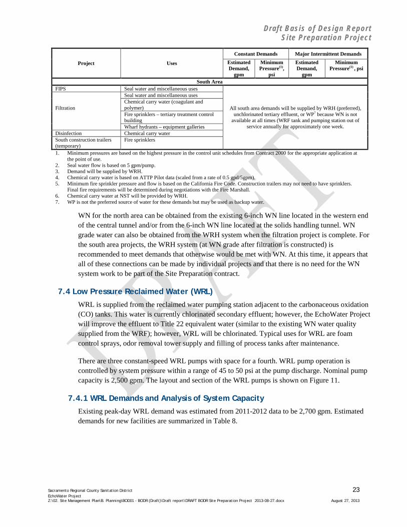
Draft Basis of Design Report Site Preparation Project
Sacramento Regional County Sanitation District 23 EchoWater Project Z:\02. Site Management Plan\B. Planning\BOD01 - BODR (Draft)\Draft report\DRAFT BODR Site Preparation Project 2013-08-27.docx August 27, 2013
Project Uses
Constant Demands Major Intermittent Demands Estimated Demand,
gpm
Minimum Pressure(1),
psi
Estimated Demand,
gpm
Minimum Pressure(1) , psi
South Area FIPS Seal water and miscellaneous uses
All south area demands will be supplied by WRH (preferred), unchlorinated tertiary effluent, or WP7 because WN is not
available at all times (WRF tank and pumping station out of service annually for approximately one week.
Filtration
Seal water and miscellaneous uses Chemical carry water (coagulant and polymer) Fire sprinklers – tertiary treatment control building Wharf hydrants – equipment galleries
Disinfection Chemical carry water South construction trailers (temporary)
Fire sprinklers
1. Minimum pressures are based on the highest pressure in the control unit schedules from Contract 2000 for the appropriate application at the point of use.
2. Seal water flow is based on 5 gpm/pump. 3. Demand will be supplied by WRH. 4. Chemical carry water is based on ATTP Pilot data (scaled from a rate of 0.5 gpd/5gpm). 5. Minimum fire sprinkler pressure and flow is based on the California Fire Code. Construction trailers may not need to have sprinklers.
Final fire requirements will be determined during negotiations with the Fire Marshall. 6. Chemical carry water at NST will be provided by WRH. 7. WP is not the preferred source of water for these demands but may be used as backup water.
WN for the north area can be obtained from the existing 6-inch WN line located in the western end of the central tunnel and/or from the 6-inch WN line located at the solids handling tunnel. WN grade water can also be obtained from the WRH system when the filtration project is complete. For the south area projects, the WRH system (at WN grade after filtration is constructed) is recommended to meet demands that otherwise would be met with WN. At this time, it appears that all of these connections can be made by individual projects and that there is no need for the WN system work to be part of the Site Preparation contract.
7.4 Low Pressure Reclaimed Water (WRL)
WRL is supplied from the reclaimed water pumping station adjacent to the carbonaceous oxidation (CO) tanks. This water is currently chlorinated secondary effluent; however, the EchoWater Project will improve the effluent to Title 22 equivalent water (similar to the existing WN water quality supplied from the WRF); however, WRL will be chlorinated. Typical uses for WRL are foam control sprays, odor removal tower supply and filling of process tanks after maintenance.
There are three constant-speed WRL pumps with space for a fourth. WRL pump operation is controlled by system pressure within a range of 45 to 50 psi at the pump discharge. Nominal pump capacity is 2,500 gpm. The layout and section of the WRL pumps is shown on Figure 11.
7.4.1 WRL Demands and Analysis of System Capacity
Existing peak-day WRL demand was estimated from 2011-2012 data to be 2,700 gpm. Estimated demands for new facilities are summarized in Table 8.
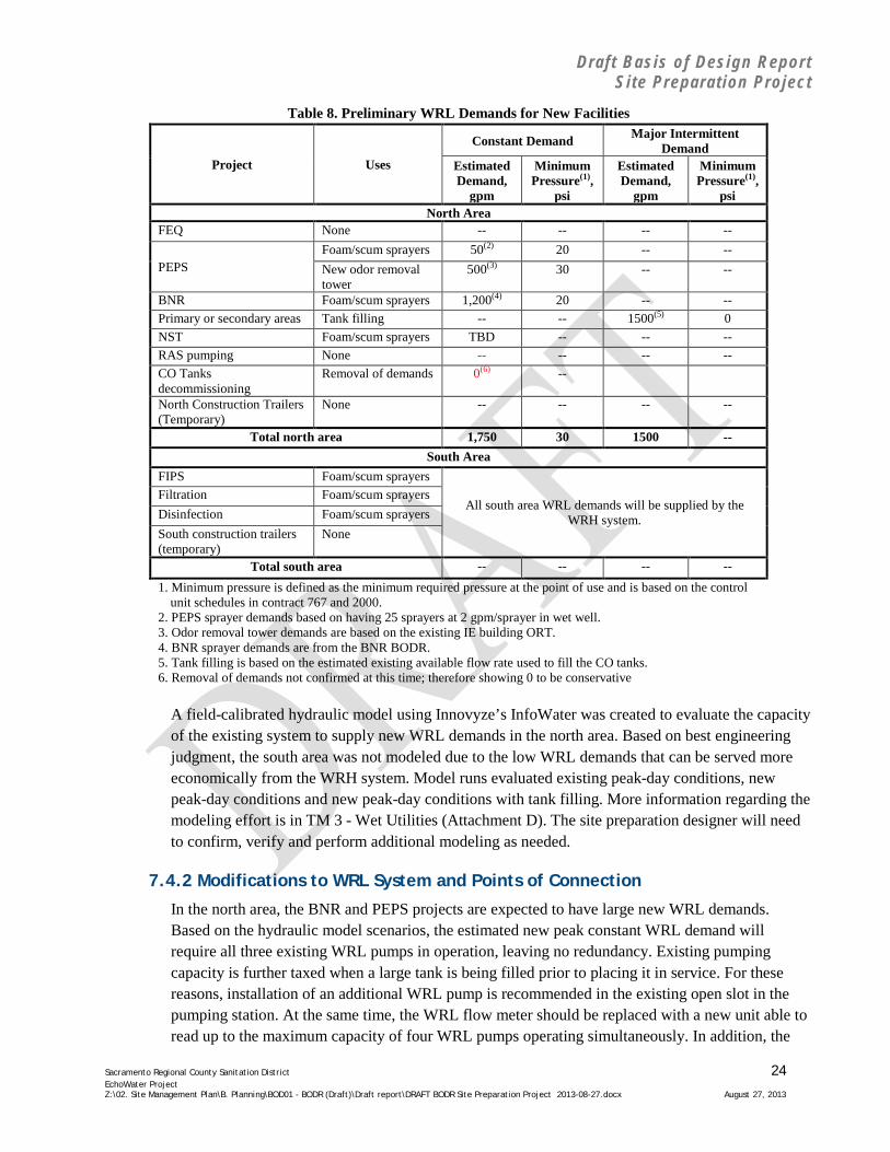
Draft Basis of Design Report Site Preparation Project
Sacramento Regional County Sanitation District 24 EchoWater Project Z:\02. Site Management Plan\B. Planning\BOD01 - BODR (Draft)\Draft report\DRAFT BODR Site Preparation Project 2013-08-27.docx August 27, 2013
Table 8. Preliminary WRL Demands for New Facilities
Project Uses
Constant Demand Major Intermittent Demand
Estimated Demand,
gpm
Minimum Pressure(1),
psi
Estimated Demand,
gpm
Minimum Pressure(1),
psi North Area
FEQ None -- -- -- --
PEPS Foam/scum sprayers 50(2) 20 -- -- New odor removal tower
500(3) 30 -- --
BNR Foam/scum sprayers 1,200(4) 20 -- -- Primary or secondary areas Tank filling -- -- 1500(5) 0 NST Foam/scum sprayers TBD -- -- -- RAS pumping None -- -- -- -- CO Tanks decommissioning
Removal of demands 0(6) --
North Construction Trailers (Temporary)
None -- -- -- --
Total north area 1,750 30 1500 -- South Area
FIPS Foam/scum sprayers
All south area WRL demands will be supplied by the WRH system.
Filtration Foam/scum sprayers Disinfection Foam/scum sprayers South construction trailers (temporary)
None
Total south area -- -- -- -- 1. Minimum pressure is defined as the minimum required pressure at the point of use and is based on the control
unit schedules in contract 767 and 2000. 2. PEPS sprayer demands based on having 25 sprayers at 2 gpm/sprayer in wet well. 3. Odor removal tower demands are based on the existing IE building ORT. 4. BNR sprayer demands are from the BNR BODR. 5. Tank filling is based on the estimated existing available flow rate used to fill the CO tanks. 6. Removal of demands not confirmed at this time; therefore showing 0 to be conservative
A field-calibrated hydraulic model using Innovyze’s InfoWater was created to evaluate the capacity of the existing system to supply new WRL demands in the north area. Based on best engineering judgment, the south area was not modeled due to the low WRL demands that can be served more economically from the WRH system. Model runs evaluated existing peak-day conditions, new peak-day conditions and new peak-day conditions with tank filling. More information regarding the modeling effort is in TM 3 - Wet Utilities (Attachment D). The site preparation designer will need to confirm, verify and perform additional modeling as needed.
7.4.2 Modifications to WRL System and Points of Connection
In the north area, the BNR and PEPS projects are expected to have large new WRL demands. Based on the hydraulic model scenarios, the estimated new peak constant WRL demand will require all three existing WRL pumps in operation, leaving no redundancy. Existing pumping capacity is further taxed when a large tank is being filled prior to placing it in service. For these reasons, installation of an additional WRL pump is recommended in the existing open slot in the pumping station. At the same time, the WRL flow meter should be replaced with a new unit able to read up to the maximum capacity of four WRL pumps operating simultaneously. In addition, the

Draft Basis of Design Report Site Preparation Project
Sacramento Regional County Sanitation District 25 EchoWater Project Z:\02. Site Management Plan\B. Planning\BOD01 - BODR (Draft)\Draft report\DRAFT BODR Site Preparation Project 2013-08-27.docx August 27, 2013
District may require a fifth WRL pump to be installed within the system to allow for extended maintenance of one of the WRL pumps and still provide continuous availability of a spare. Specific location and alternatives for this additional WRL pump will have to be researched and coordinated with District Engineering and Operations.
A new WRL loop and grid within the BNR and PEPS project footprints is recommended to supply the BNR and PEPS structures with WRL. This loop and grid should be constructed by the BNR and PEPS projects. The two points of connection for this new loop in the model were the 12-inch line in the north tunnel and the 12-inch ACP line leading to the IJS; however, additional points of connection are available and should be considered for redundancy and to better balance supply to the loop. Table 9 provides a list of nearby points of connections for each EchoWater project.
Table 9. WRL Points of Connections
Area Points of Connection
North Area BNR • 12-inch line at the west end of the central tunnel and in
the north tunnel • 12-inch line near the final effluent/primary effluent
diversion structure • 12-inch line leading from the solids handling tunnel to
the influent junction structure (IJS). This line is ACP. • 14-inch line at the corner of the solids handling tunnel
PEPS
FEQ WRL not required NST
North construction trailers (temporary)
South Area FIPS
Provided by WRH Filtration area Disinfection South construction trailers (temporary)
The nearest WRL line for the south area is the 8-inch line located west of the I/E Building. This line is small and distant from the new demands. The closest main line is in the central tunnel approximately 2,600 feet from the south area. Demands for WRL in the south area projects are principally for foam and scum sprayers and are small. This minor WRL demand is better supplied via the new south area WRH loop (see Section 7.5) to reduce construction costs and pipe congestion.
7.5 High-Pressure Reclaimed Water (WRH)
Like WRL, WRH is supplied from the reclaimed water pumping station adjacent to the carbonaceous oxidation (CO) tanks. This water is currently chlorinated secondary effluent; however, the EchoWater Project will improve the effluent to Title 22 equivalent water (similar to the existing WRF water quality); however, WRH will be chlorinated. Typical uses of WRH are washdown, chemical dilution or carry, and fire hydrant supply.

Draft Basis of Design Report Site Preparation Project
Sacramento Regional County Sanitation District 26 EchoWater Project Z:\02. Site Management Plan\B. Planning\BOD01 - BODR (Draft)\Draft report\DRAFT BODR Site Preparation Project 2013-08-27.docx August 27, 2013
There are four constant-speed WRH pumps but, unlike WRL, there is no space at the current location for additional pumps. These pumps were installed in 1996 under Contract 2745 and replaced the original WRH pumps. WRH pump operation is controlled by system pressure within a range of 110 to 130 psi at the pump discharge. Nominal existing pump capacity is 2,600 gpm per pump. Layout and section of the WRH pumps is shown on Figure 12.
7.5.1 WRH Demands and Analysis of System Capacity
Existing peak-day WRH demand was estimated from 2011-2012 data to be 3,700 gpm. Estimated demands for new facilities are summarized in Table 10. The largest new demand is washdown of the ESBs which is estimated to be 1,850 to 3,700 gpm, depending whether one or two washdown monitors are in use. The other major use is fire hydrant flow which is estimated at 2,000 gpm as described in Section 7.1. Fire flow is not simultaneous with ESB washdown because the washdown activity could be stopped in the event of a fire.
A field-calibrated hydraulic model using Innovyze’s InfoWater was created to evaluate the capacity of the existing system to supply new WRH demands. Model runs were completed for existing peak-day conditions and existing peak-day conditions with fire flow using the existing pumps and distribution system. When using three pumps (one standby), fire flow was found to be inadequate at several hydrants mainly in areas with weak distribution. More information regarding the modeling effort is included in TM 3 Wet Utilities (Attachment D). The site preparation designer will need to confirm, verify and perform additional modeling as needed
Subsequent model runs were conducted using the maximum size impeller available for the existing pumps. An 18-inch loop was added to the north area and a 10-inch loop to the south area as well as other distribution system enhancements as described in more detail below. The model runs included new peak-day demand plus fire flow and new peak-day demands plus one or two ESB washdown monitors. Using three of four higher capacity pumps and distribution system enhancements, fire flow was adequate at modeled hydrants located at several points in existing and new facility areas. Similarly, three of four higher capacity pumps can supply one ESB washdown monitor; however, all four pumps are needed to supply two monitors.
7.5.2 Modifications to WRH System and Points of Connection
The recommended WRH system improvements are divided into three categories:
• WRH pumping station improvements
• North area distribution system improvements
• South area distribution system improvements
7.5.2.1 WRH Pumping Station Improvements Higher capacity WRH pumps are recommended to meet the new demands and to correct some deficiencies in existing fire flow capacity. Based on hydraulic network modeling, higher capacity can be achieved with new maximum-diameter impellers (18 inches) and new motors (estimated at 300 hp). The new motors will require upgrades to the power feeds from the MCC. The modified
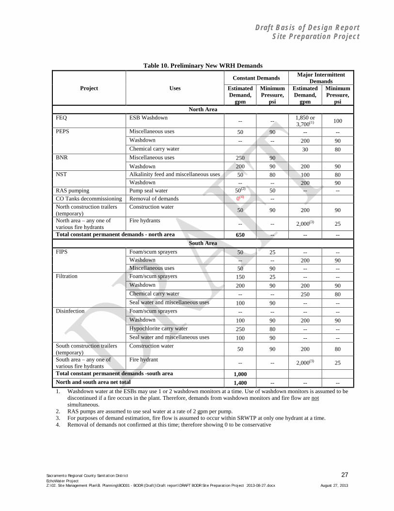
Draft Basis of Design Report Site Preparation Project
Sacramento Regional County Sanitation District 27 EchoWater Project Z:\02. Site Management Plan\B. Planning\BOD01 - BODR (Draft)\Draft report\DRAFT BODR Site Preparation Project 2013-08-27.docx August 27, 2013
Table 10. Preliminary New WRH Demands
Project Uses
Constant Demands Major Intermittent Demands
Estimated Demand,
gpm
Minimum Pressure,
psi
Estimated Demand,
gpm
Minimum Pressure,
psi North Area
FEQ ESB Washdown -- -- 1,850 or 3,700(1) 100
PEPS Miscellaneous uses 50 90 -- -- Washdown -- -- 200 90 Chemical carry water 30 80
BNR Miscellaneous uses 250 90 Washdown 200 90 200 90
NST Alkalinity feed and miscellaneous uses 50 80 100 80 Washdown -- -- 200 90
RAS pumping Pump seal water 50(2) 50 -- -- CO Tanks decommissioning Removal of demands 0(4) -- North construction trailers (temporary)
Construction water 50 90 200 90
North area – any one of various fire hydrants
Fire hydrants -- -- 2,000(3) 25
Total constant permanent demands - north area 650 -- -- -- South Area
FIPS Foam/scum sprayers 50 25 -- -- Washdown -- -- 200 90 Miscellaneous uses 50 90 -- --
Filtration Foam/scum sprayers 150 25 -- -- Washdown 200 90 200 90 Chemical carry water -- -- 250 80 Seal water and miscellaneous uses 100 90 -- --
Disinfection
Foam/scum sprayers -- -- -- -- Washdown 100 90 200 90 Hypochlorite carry water 250 80 -- -- Seal water and miscellaneous uses 100 90 -- --
South construction trailers (temporary)
Construction water 50 90 200 80
South area – any one of various fire hydrants
Fire hydrant -- -- 2,000(3) 25
Total constant permanent demands -south area 1,000 North and south area net total 1,400 -- -- -- 1. Washdown water at the ESBs may use 1 or 2 washdown monitors at a time. Use of washdown monitors is assumed to be
discontinued if a fire occurs in the plant. Therefore, demands from washdown monitors and fire flow are not simultaneous.
2. RAS pumps are assumed to use seal water at a rate of 2 gpm per pump. 3. For purposes of demand estimation, fire flow is assumed to occur within SRWTP at only one hydrant at a time. 4. Removal of demands not confirmed at this time; therefore showing 0 to be conservative
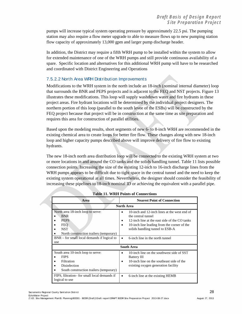
Draft Basis of Design Report Site Preparation Project
Sacramento Regional County Sanitation District 28 EchoWater Project Z:\02. Site Management Plan\B. Planning\BOD01 - BODR (Draft)\Draft report\DRAFT BODR Site Preparation Project 2013-08-27.docx August 27, 2013
pumps will increase typical system operating pressure by approximately 22.5 psi. The pumping station may also require a flow meter upgrade to able to measure flows up to new pumping station flow capacity of approximately 13,000 gpm and larger pump discharge header.
In addition, the District may require a fifth WRH pump to be installed within the system to allow for extended maintenance of one of the WRH pumps and still provide continuous availability of a spare. Specific location and alternatives for this additional WRH pump will have to be researched and coordinated with District Engineering and Operations
7.5.2.2 North Area WRH Distribution Improvements
Modifications to the WRH system in the north include an 18-inch (nominal internal diameter) loop that surrounds the BNR and PEPS projects and is adjacent to the FEQ and NST projects. Figure 13 illustrates these modifications. This loop will supply washdown water and fire hydrants in these project areas. Fire hydrant locations will be determined by the individual project designers. The northern portion of this loop (parallel to the south levee of the ESBs) will be constructed by the FEQ project because that project will be in construction at the same time as site preparation and requires this area for construction of parallel utilities.
Based upon the modeling results, short segments of new 6- to 8-inch WRH are recommended in the existing chemical area to create loops for better fire flow. These changes along with new 18-inch loop and higher capacity pumps described above will improve delivery of fire flow to existing hydrants.
The new 18-inch north area distribution loop will be connected to the existing WRH system at two or more locations in and around the CO tanks and the solids handling tunnel. Table 11 lists possible connection points. Increasing the size of the existing 12-inch to 16-inch discharge lines from the WRH pumps appears to be difficult due to tight space in the central tunnel and the need to keep the existing system operational at all times. Nevertheless, the designer should consider the feasibility of increasing these pipelines to 18-inch nominal ID or achieving the equivalent with a parallel pipe.
Table 11. WRH Points of Connections Area Nearest Point of Connection
North Area North area 18-inch loop to serve: • BNR • PEPS • FEQ • NST • North construction trailers (temporary)
• 10-inch and 12-inch lines at the west end of the central tunnel
• 12-inch line at the east side of the CO tanks • 10-inch line leading from the corner of the
solids handling tunnel to ESB-A
BNR – for small local demands if logical to use
• 6-inch line in the north tunnel
South Area South area 10-inch loop to serve: • FIPS • Filtration • Disinfection • South construction trailers (temporary)
• 10-inch line on the southwest side of SST Battery III
• 10-inch line on the southeast side of the existing oxygen generation facility
FIPS, filtration– for small local demands if logical to use
• 6-inch line at the existing HEMB

Draft Basis of Design Report Site Preparation Project
Sacramento Regional County Sanitation District 29 EchoWater Project Z:\02. Site Management Plan\B. Planning\BOD01 - BODR (Draft)\Draft report\DRAFT BODR Site Preparation Project 2013-08-27.docx August 27, 2013
7.5.2.3 South Area WRH Distribution System Improvements The south area WRH system modifications consist primarily of constructing a 10-inch (nominal ID) loop around the tertiary treatment site and extending this 10-inch system west along SSB-1 Road to tie into existing pipe at the northwest corner of dedicated land disposal (DLD) - 1. A 10-inch diameter is recommended to match the size of the existing pipe it will connect to near the SSTs and to provide capacity for additional demands that are not foreseen at this time. Figure 13 illustrates these modifications.
The loop around the tertiary treatment site will provide process water and fire hydrant supply to the tertiary area projects, and to the south area construction trailers. Fire hydrant locations will be determined by the individual project designers. Connection points are listed in Table 11 and consist of an existing 10-inch line at the southwest corner of the SSTs and a 10-inch line on the southeast side of the existing oxygen generation facility.
The 10-inch extension along SSB-1 Road will provide fire hydrant water to the relocated HEMB and the Harvest Crew Building. The tie-in to existing WRH pipe at the northwest corner of DLD-1 will strengthen fire protection for the former Wheelabrator Building and the NST process. The 10-inch WRH from the SSTs along SSB-1 Road should be constructed under the Harvest Crew building project because this project will precede site preparation and will need fire protection. The remainder of the loop will be constructed under the site preparation contract.
A smaller 6-inch line is located at the existing HEMB and serves a fire hydrant. It could be used for small local demands at the FIPS or filtration projects if it makes sense to do so. Table 11 presents a summary of the points of connection to the WRH system.
7.5.3 Failures of WRL and WRH Pipe
Both the WRL and WRH systems contain aging pipe, some of which is asbestos cement pipe (ACP). Leaks and pipe failures (particularly ACP) have begun to occur with some regularity. The District prepared a Business Case Evaluation (BCE) for replacement of ACP in the WRH system (SRWTP WRH ACP Replacement Project, March 2009), which concluded that the most cost-effective approach to pipe failures was to replace the pipe as it failed.
Given this prior determination, the approach taken for the Site Preparation Project was to include replacement of ACP only if the pipe in question had inadequate capacity to serve new needs. There were none of these conditions found; consequently, there is no replacement of ACP proposed in the Site Preparation Project for the WRH or WRL systems at this time. However, it is important to note that the modified WRH pumps will increase system pressure and this may accelerate failures of existing ACP. This BCE could be revisited and updated to determine whether or not the increase system pressure will affect the outcome of this BCE.
7.6 Nitrifying Sidestream Treatment
At least two pipelines for the NST system may require construction by the Site Preparation Project. The pipelines consist of a 6-inch waste activated sludge (WAS) line running from the NST to the RAS reaeration basin at the BNR and a 16-inch sidestream secondary effluent (SSE) to the primary

Draft Basis of Design Report Site Preparation Project
Sacramento Regional County Sanitation District 30 EchoWater Project Z:\02. Site Management Plan\B. Planning\BOD01 - BODR (Draft)\Draft report\DRAFT BODR Site Preparation Project 2013-08-27.docx August 27, 2013
effluent diversion structure and primary effluent channel. The SSE line will require additional design considerations to allow complete pipeline purging and draining. The Site Preparation designer shall coordinate with the NST project, the BNR project, and the PEPS project to evaluate possible routing and sizing alternatives.
7.7 Sanitary Drainage
The sanitary drainage (SD) system conveys wastewater from the drains, toilets, sinks, and showers throughout the plant back to the plant influent. New sanitary drain demands are minor in both the north and south areas. Each area is expected to have personnel space within a new area control center (ACC) for operations staff. The new north ACC will be part of the BNR Project and the new south ACC will be part of the Filtration Project. For purposes of this BODR, the SD demands will be equal to the potable water demands provided in Section 7.2.
7.7.1 Recommended SD System Modifications and Points of Connection
As the SD demands are small and there are points of connection available in the vicinity of the north and south area projects, modifications of the SD system under the site preparation contract are not necessary. Points of connection to the SD system for the north and south projects are presented in Table 12.
Table 12. Sanitary Drain Points of Connections Area Location
North Area BNR 96-inch RS (raw sewage or City Interceptor) running west-east on the
south of ESBs A, B, C and north of ESB-D and BNR PEPS FEQ NST 36-inch SN (supernatant) that runs north-south on the east side of SSB I
and ESB-D. North construction trailers (temporary) South Area
FIPS 12-inch SD line located on the northeast side of the intersection of Reclamation Way and Central Street. 18-inch SD line is located on the west edge of the water reclamation plant near the intersection of Reclamation Way and Sims Road.
Filtration
Disinfection South construction trailers (temporary) 12”SD located on the northeast side of the intersection of Reclamation
Way and Central Street.(1) (1)PMO/CMID building (an early completion project) also will connect to the 12”SD
7.8 Plant Drain
The tank drain (TD) and drain (D) lines drain all of the plant process and storage tanks, chemical tanks, and other tanks. The plant drain systems convey wastewater back to the plant influent.
7.8.1 PD Demands
None of the four projects in the north area (FEQ, BNR, PEPS, NST) is expected to have plant drain needs that require support from the Site Preparation Project. Draining of ESBs under the FEQ project is part of that project’s scope in which the ESBs will be drained to the influent conduit or
Draft Basis of Design Report Site Preparation Project
Sacramento Regional County Sanitation District 31 EchoWater Project Z:\02. Site Management Plan\B. Planning\BOD01 - BODR (Draft)\Draft report\DRAFT BODR Site Preparation Project 2013-08-27.docx August 27, 2013
the City Interceptor through existing and new piping. The BNR Project will have a new sump for draining tanks and channels in the BNR process. This drainage will be pumped into the BNR influent channel. The PEPS and the new PE channel extension will require connection to existing plant drain lines. A review of existing lines indicates that there are ample options to handle plant drainage from the PEPS project and there should be no need for Site Preparation Project involvement. Similarly, the NST project does not need Site Preparation Project support because it is located adjacent to the existing 36-inch SN line that ties directly to the City Interceptor.
The south area projects (FIPS, filtration, and disinfection) will all require draining of the basins and channels. The drained wastewater will be collected at a new plant drain pumping station proposed to be centrally located and constructed under the Filtration Project. Collected drainage would be pumped to existing piping systems for conveyance to either (1) the plant influent via the SD system, (2) to Sump 404 via the TD system serving the SSTs, or (3) back to the filter flow distribution structure (FFDS) to reduce impact on the primary and secondary processes. It is recommended that the filtration project create a south area tank drain sump to drain all area channels and tanks into the SD system for conveyance to the plant influent.
7.9 Storm Drainage
On-site stormwater is collected through approximately 32,000 linear feet of pipe to the Storm Water Pump Station (SWPS) located on the eastern edge of the plant shown on Figure 1. The SWPS contains five pumps. Currently, Pump 5 (and sometimes Pump 4) is used and discharges stormwater and non-stormwater flow to the headworks, where it is then treated within the treatment facilities.
There are several alternatives and options considered for area wide storm drainage. Refer to TM 05 for a more detailed analysis. Two hydrologic SacCalc models were developed as part of TM 05. The Lee & Ro, Inc. 2007 SDMP existing conditions model was used as the basis for developing proposed options after verifying with SRCSD staff that no significant changes in land use have occurred since the development of the model in 2007. The site preparation designer will need to confirm, verify and perform additional modeling as needed.
The various proposed alternatives must be confirmed and further evaluated to select an option or a modified option that best suits the construction sequencing and needs of the process projects. Some of the locations for detention basins prohibit construction by the Site Preparation Project due to timing constraints and space requirements for process project construction. There is an existing 12-inch which increases to an 18-inch STD running north/south from the primaries that crosses the BNR footprint that will need to be relocated/redirected/connected by the Site Preparation Project prior to the mass excavation by the FEQ project. There is an existing Tank Drain pipeline at the primaries that can be used for this connection temporarily. There are also existing STD pipelines within the filtration and disinfection footprints which will have to be evaluated and determine which contract should include design and construction. Figure 14 includes an overview of the existing shed areas and Figure 15 shows one of the alternatives for detention basins and new pipelines. The other alternatives are included in TM 05.
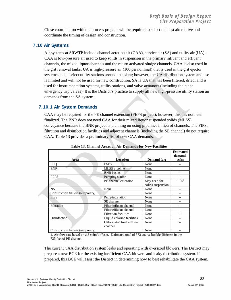
Draft Basis of Design Report Site Preparation Project
Sacramento Regional County Sanitation District 32 EchoWater Project Z:\02. Site Management Plan\B. Planning\BOD01 - BODR (Draft)\Draft report\DRAFT BODR Site Preparation Project 2013-08-27.docx August 27, 2013
Close coordination with the process projects will be required to select the best alternative and coordinate the timing of design and construction.
7.10 Air Systems
Air systems at SRWTP include channel aeration air (CAA), service air (SA) and utility air (UA). CAA is low-pressure air used to keep solids in suspension in the primary influent and effluent channels, the mixed liquor channels and the return activated sludge channels. CAA is also used in the grit removal tanks. UA is high-pressure air (100 psi nominal) that is used in the grit ejector systems and at select utility stations around the plant; however, the UA distribution system and use is limited and will not be used for new construction. SA is UA that has been filtered, dried, and is used for instrumentation systems, utility stations, and valve actuators (including the plant emergency trip valves). It is the District’s practice to supply all new high-pressure utility station air demands from the SA system.
7.10.1 Air System Demands
CAA may be required for the PE channel extension (PEPS project); however, this has not been finalized. The BNR does not need CAA for their mixed liquor suspended solids (MLSS) conveyance because the BNR project is planning on using pipelines in lieu of channels. The FIPS, filtration and disinfection facilities and adjacent channels (including the SE channel) do not require CAA. Table 13 provides a preliminary list of new CAA demands.
Table 13. Channel Aeration Air Demands for New Facilities
Area Location Demand for:
Estimated demand,
scfm FEQ ESBs None -- BNR MLSS pipeline None --
BNR basins None -- PEPS Pumping station None --
PE channel extension May need for solids suspension
11001
NST None None -- Construction trailers (temporary) None -- FIPS Pumping station None --
SE channel None -- Filtration Filter influent channel None --
Filter effluent channel None -- Filtration facilities None --
Disinfection Liquid chlorine facilities None -- Chlorinated final effluent channel
None --
Construction trailers (temporary) None -- 1. Air flow rate based on a 3 scfm/diffuser. Estimated total of 372 coarse bubble diffusers in the 725 feet of PE channel.
The current CAA distribution system leaks and operating with oversized blowers. The District may prepare a new BCE for the existing inefficient CAA blowers and leaky distribution system. If prepared, this BCE will assist the District in determining how to best rehabilitate the CAA system.
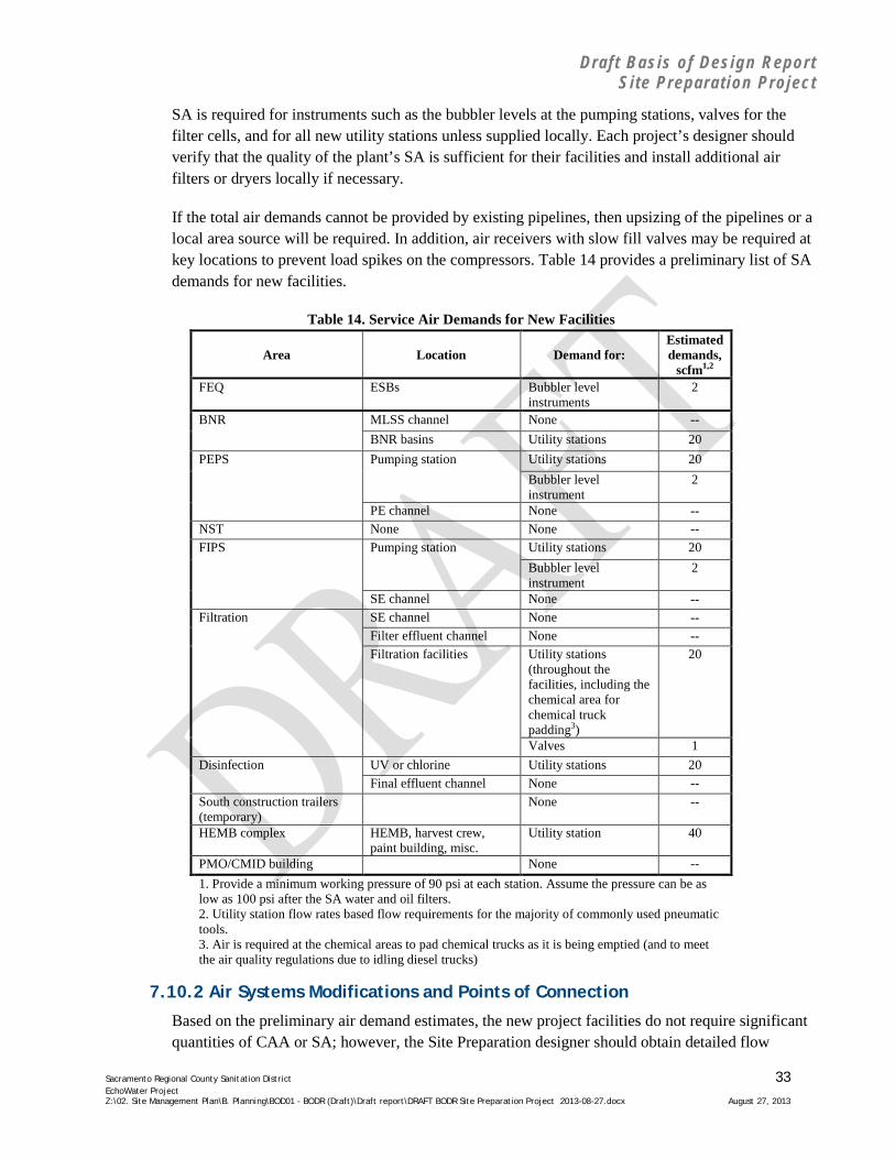
Draft Basis of Design Report Site Preparation Project
Sacramento Regional County Sanitation District 33 EchoWater Project Z:\02. Site Management Plan\B. Planning\BOD01 - BODR (Draft)\Draft report\DRAFT BODR Site Preparation Project 2013-08-27.docx August 27, 2013
SA is required for instruments such as the bubbler levels at the pumping stations, valves for the filter cells, and for all new utility stations unless supplied locally. Each project’s designer should verify that the quality of the plant’s SA is sufficient for their facilities and install additional air filters or dryers locally if necessary.
If the total air demands cannot be provided by existing pipelines, then upsizing of the pipelines or a local area source will be required. In addition, air receivers with slow fill valves may be required at key locations to prevent load spikes on the compressors. Table 14 provides a preliminary list of SA demands for new facilities.
Table 14. Service Air Demands for New Facilities
Area Location Demand for: Estimated demands,
scfm1,2
FEQ ESBs Bubbler level instruments
2
BNR MLSS channel None -- BNR basins Utility stations 20
PEPS Pumping station Utility stations 20 Bubbler level instrument
2
PE channel None -- NST None None -- FIPS Pumping station Utility stations 20
Bubbler level instrument
2
SE channel None -- Filtration SE channel None --
Filter effluent channel None -- Filtration facilities Utility stations
(throughout the facilities, including the chemical area for chemical truck padding3)
20
Valves 1 Disinfection UV or chlorine Utility stations 20
Final effluent channel None -- South construction trailers (temporary)
None --
HEMB complex HEMB, harvest crew, paint building, misc.
Utility station 40
PMO/CMID building None -- 1. Provide a minimum working pressure of 90 psi at each station. Assume the pressure can be as low as 100 psi after the SA water and oil filters. 2. Utility station flow rates based flow requirements for the majority of commonly used pneumatic tools. 3. Air is required at the chemical areas to pad chemical trucks as it is being emptied (and to meet the air quality regulations due to idling diesel trucks)
7.10.2 Air Systems Modifications and Points of Connection
Based on the preliminary air demand estimates, the new project facilities do not require significant quantities of CAA or SA; however, the Site Preparation designer should obtain detailed flow
Draft Basis of Design Report Site Preparation Project
Sacramento Regional County Sanitation District 34 EchoWater Project Z:\02. Site Management Plan\B. Planning\BOD01 - BODR (Draft)\Draft report\DRAFT BODR Site Preparation Project 2013-08-27.docx August 27, 2013
demands (uses, flow, and pressure) from each project’s designer to confirm this finding. At this time, the following conclusions and recommendations are made with respect to plant air systems:
Channel Aeration Air
• The BNR project will provide a local and independent CAA system for that project’s needs.
• Once the PEPS project confirms the need and demand for CAA, various points of connection to the existing CAA system can be evaluated for capacity by the Site Preparation Project designer. The nearest CAA pipeline of sufficient size is the 20-inch line located adjacent to the diversion structure on the north side of the CAA duct alongside the central tunnel.
• The District may decide to upgrade/rehabilitate the existing CAA system to fix leaks as a separate project.
• The BNR designer should coordinate with the PEPS designer to determine if CAA demands for the PE channel extension can be served by the BNR-provided CAA system.
Utility Air
• There are no new UA demands. Continuing the current practice of using SA for all new utility stations is recommended.
Service Air
• The individual project designers should make definitive estimates of SA demands and then work with the PMO to determine whether to connect to the existing plant system or provide a local independent system(s). If the existing air system does not provide enough air, then a local area source should be constructed to provide air for the north or south areas.
• When considering new local systems, project designers should coordinate with the PMO, adjacent projects, and assess the feasibility of a local system to serve multiple projects. The local area source should be shared to reduce redundancy and associated maintenance burden.
• Flow and pressure meters should be installed at all new connections and/or key locations to help maintain the integrity of the SA system. These meters should be wired to the plant computer control system (PCCS) where possible to assist SRWTP in monitoring the condition of the SA system and to better isolate the location of leaks.
Based on the conclusions and recommendations above, it does not appear necessary for the Site Preparation Project to extend any of the air systems to the individual project sites. In all cases, there are either points of connection to existing systems close by or there is the alternative of constructing new local air system(s) as part of one or more projects. The PMO site management team will continue to help coordinate the air system needs of new projects with existing systems.
Draft Basis of Design Report Site Preparation Project
Sacramento Regional County Sanitation District 35 EchoWater Project Z:\02. Site Management Plan\B. Planning\BOD01 - BODR (Draft)\Draft report\DRAFT BODR Site Preparation Project 2013-08-27.docx August 27, 2013
7.11 Electrical Power
The SRWTP main electrical substation will be expanded for the new loads associated with the EchoWater project. This work will be accomplished under a separate project and will not be part of the Site Preparation Project. An update to the electrical power master plan is in progress. If it is determined that new 12kV ductbanks are needed from the main substation to new process areas, those ductbanks will be constructed as part of this project.
7.12 Plant Communications
There is an existing plant-wide fiber optic backbone cable consisting of 72 strands (12 single-mode and 60 multimode fibers) installed in a loop configuration around the plant, as shown on Figure 16. This fiber optic backbone supports several plant networks which must be maintained throughout the EchoWater Project. Detailed descriptions of the existing system are included in TM 07 and the Plant Computer Control System (PCCS) Master Plan, June 2013.
Also included in TM 07 is an overview of the expansion of the existing fiber optic network and signal ductbanks for the new EchoWater projects. In the site preparation project, there will be signal ductbanks and cabling in several locations Refer to Figures 17, 18, 26 and 27:
1. Tertiary site relocated signal ductbank. Refer to Section 8.7 for further description. This includes ductbank, cable installation and cable removal. Ductbanks will be left in place for demolition by FIPS, Filtration and Disinfection projects.
2. Security guard facility. This includes new signal ductbanks and cabling. Refer to Section 4.1 for further description.
3. Relocated Materials Testing Lab and Paint Building can be supplied communications via a temporary connection from the North Contractor radio tower. Then subsequently, when the NST contract is underway, a permanent connection to the fiber optic system could be extended to these facilities under that project.
4. North Area projects (BNR, FEQ, NST and PEPS) will be installed by these projects.
5. North Area: A portion of the Relocated Materials Testing Lab and Paint Building signal ductbank with an extension to SSB-I will be included in the Site Preparation
6. South Area (Filtration, Disinfection, PEPS) will be installed by these projects.
7.13 Utilities for Relocated Buildings
Utilities (water, sewer, electrical, storm drainage, and communication) will be needed for the PMO/CMID Building, Bufferlands and Harvest Crew Building, HEMB and fuel station, Paint Building, and Materials Testing Lab. Locations of these buildings are identified on Figure 1.
The PMO/CMID and Bufferlands and Harvest Crew buildings will be completed before the Site Preparation Project begins. Each of these three projects can provide their own utility connections from nearby facilities. The Bufferlands and Harvest Crew Building Project will construct utility
Draft Basis of Design Report Site Preparation Project
Sacramento Regional County Sanitation District 36 EchoWater Project Z:\02. Site Management Plan\B. Planning\BOD01 - BODR (Draft)\Draft report\DRAFT BODR Site Preparation Project 2013-08-27.docx August 27, 2013
extensions with capacity to serve the HEMB as well. The HEMB will be constructed at a later date after the program EIR is certified. The Paint Building and Materials Testing Lab is being designed by District Engineering and may be constructed prior to the Site Preparation Project. These projects will provide their own utility connections from the existing Wheelabrator facility, but will need to be coordinated with the Site Preparation Project. For these reasons, there is no reason for the Site Preparation Project to extend utilities to relocated buildings.
8.0 Relocation of Utilities and Process Piping
Based on the facility layouts and routing of major yard piping and channels currently planned for the major process projects, there are a number of buried process piping runs and ductbanks that are in conflict with the new facilities. These utilities and process pipes need to be relocated to clear the sites for the various projects and are described below. As noted above, only those relocations that are logical to construct outside of the individual projects are included in the Site Preparation Project. Additional information is contained in TM 6 – Process Piping and Ductbank Relocations (Attachment G).
8.1 North Project Area
The north project area encompassing the BNR, PEPS, NST, and FEQ projects is relatively open with two major utility/process piping corridors that constitute the majority of conflicts with new facilities. The utilities in these corridors are described below.
8.1.1 Utilities and Process Piping North of BNR
This corridor is located between the south levee of the ESBs and the BNR is shown on Figure 19. The corridor contains the following process piping and utilities:
• 96-inch RS (raw sewage – City Interceptor)
• 6-inch CLS (chlorine solution)
• 14-inch WP (potable water)
• 36-inch STD (storm drain)
• 6-inch SOV (sulfur dioxide vacuum)
• 8-inch SOV (2 lines)
• 3-inch OHP (oxygen high pressure) – abandoned, but may be reactivated
• 12kV ductbank (power to ESB-D)
Portions of the 6-inch CLS, 14-inch WP, 36-inch STD, and the SOV lines are in conflict with the BNR structure and need to be relocated more or less parallel to their existing alignments and a moderate distance away. The 96-inch RS and 3-inch OHP are deep and not in conflict. The 12kV ductbank is in conflict with a new 84-inch line that is part of the FEQ project. The ductbank must to be relocated a moderate distance northward over its entire length.
Draft Basis of Design Report Site Preparation Project
Sacramento Regional County Sanitation District 37 EchoWater Project Z:\02. Site Management Plan\B. Planning\BOD01 - BODR (Draft)\Draft report\DRAFT BODR Site Preparation Project 2013-08-27.docx August 27, 2013
Given the relative schedules of the FEQ, BNR and Site Preparation Projects, there is no advantage to the Site Preparation Project performing any of this relocation work. FEQ and Site Preparation are expected to start construction at the same time (early 2015) and BNR will follow in early 2016. With these schedule overlaps, there is no opportunity for the Site Preparation Project to complete the work early. Therefore, piping and ductbank relocations in the north area will be handled by the individual projects as described in their BODR (FEQ) and preliminary design report (BNR).
8.1.2 Utilities and Process Piping East of BNR
This corridor is located east of the BNR project as shown on Figure 19. This corridor contains the following process piping and utilities:
• 72-inch PE (primary effluent) – two parallel lines
• 6-inch CLV (chlorine vacuum) – two parallel lines
• 3-inch OHP (oxygen high pressure) – abandoned, but may be reactivated
• 8-inch WRH
• 4-inch WFP (fire protection)
• 12kV ductbank
All of these lines are in conflict with the PEPS project, but there is no apparent advantage to modify any of them as part of site preparation; all can be relocated or modified as part of PEPS.
Therefore, the proposed approach is that the north projects will handle their own process piping and utility relocations. There is no apparent advantage gained from the Site Preparation Project performing this work.
8.2 South Project Area
The south project area is the site of the tertiary treatment projects (FIPS, filtration and disinfection) and several buildings that replace others being demolished. Two major corridors containing utilities and process piping cross the tertiary site in the east-west direction, one just south of the SE channel and one farther south along Reclamation Way.
8.2.1 Utilities and Process Piping South of Secondary Effluent Channel
Five digested sludge (DS) lines that feed the SSBs, two secondary effluent (SE) lines, two storm drains (STD) and other minor buried lines in this corridor are in conflict with the some or all of the FIPS, disinfection and the HEMB projects as shown on Figure 20. The utilities are listed below.
• 10-inch DS-2
• 16-inch DS-3 (asbestos cement pipe)
• 16-inch DS-4
• 16-inch DS-5
Draft Basis of Design Report Site Preparation Project
Sacramento Regional County Sanitation District 38 EchoWater Project Z:\02. Site Management Plan\B. Planning\BOD01 - BODR (Draft)\Draft report\DRAFT BODR Site Preparation Project 2013-08-27.docx August 27, 2013
• 8-inch DS-1 (digested sludge)
• 21.5-inch SE-1 (provides flushing water to SSBs)
• 16-inch SE-2 (provides utility water to Biosolids Recycling Facility (BRF))
• 8-inch SE (sends BRF return flow to the plant influent)
• 18-inch STD (2 lines)
• Signal ductbanks (2)
• Telephone
The five DS lines will be replaced by three 16-inch DS lines in a new alignment around the tertiary site as described in Section 8.3.
The 21.5-inch SE-1 and the 16-inch SE-2 are in conflict with tertiary facilities. The conflicts with the SE lines will require that the two existing SE supply pumps now installed at the effluent observation structure be relocated as well. SE relocations are described in Section 8.4 below.
The 8-inch SE line repurposed into carrying BRF return flow to the flow meter is partially above ground and will be repurposed or demolished to redirect BRF return flow to the SSBs. Routing and sizing alternative for this line will need to be evaluated.
Because the storm drains are gravity lines, they cannot simply be rerouted. Alternatives for handling interim storm drainage needs and options for build out are considered and evaluated as part of TM 5 - Storm Drainage.
There are several signal and telephone ductbanks in this area which are abandoned and no longer used. These can be demolished by the individual projects and the functions replaced as necessary as part of the new construction.
Other minor lines in the project area can be abandoned in place and demolished as necessary by the individual projects.
8.2.2 Utilities and Process Piping along Reclamation Way
This corridor contains a 12kV ductbank which supplies power to the Water Reclamation Facility, and the major pipelines listed below. These lines are in conflict with the filtration and disinfection projects. The utilities and process piping are:
• 10-inch WI (wetlands influent; conveys corrective action program (CAP) water to demonstration wetlands)
• 10-inch WNM (non-potable monitoring well water from CAP)
• 27-inch WRF (filtered reclaimed water)
• 12-inch WN (non-potable water)
Draft Basis of Design Report Site Preparation Project
Sacramento Regional County Sanitation District 39 EchoWater Project Z:\02. Site Management Plan\B. Planning\BOD01 - BODR (Draft)\Draft report\DRAFT BODR Site Preparation Project 2013-08-27.docx August 27, 2013
• 16-inch WP
• 8-inch SE (repurposed line carrying wastewater from the BRF)
• 12kV ductbank
• Signal ductbank
The existing wetlands supply pumping station and associated pipelines are in conflict with the tertiary projects. The pumping station will be demolished and a new one constructed in a different location. This will allow the 10-inch WNM and 10-inch WI lines in conflict with new treatment facilities to be abandoned and demolished as needed. The new wetlands supply pumping station and relocated lines are described in Section 8.6 and will be designed and likely constructed in a separate contract by the District (this is to be confirmed).
Based on current layouts of the tertiary treatment site, the WRF, WN, WP and SE lines have conflicts with new pipes/channels crossing at right angles, which can be addressed with localized alignment adjustments constructed under the individual process projects. A portion of the 8-inch SE line is installed above ground north of DLD-1 and will be relocated underground by the Site Preparation Project unless an alternate pipeline reroute of this line directly to the SSBs is selected.
The 12kV and signal ductbanks are proposed to be relocated parallel to the DS lines described above to the southwest corner of the tertiary treatment area. They will tie into existing ductbanks in the road on the east side of DLD-1. This work is described in Section 8.7.
8.3 Recommended DS Piping Relocation
As shown on Figure 21, three parallel 16-inch DS lines will be routed from DS Pad 2 around the tertiary treatment area along Central Street and South Landfill Way. Stub-outs will be installed on the new lines to feed future SSB batteries south of Landfill Way and Glacier Way. TM 6 – Process Piping and Ductbank Relocation (Attachment G) provides more information on the DS piping system.
From Landfill Way, the new lines will be routed to the southwest corner of DLD-1. At this point, a new DS Pad 3 will be constructed to distribute DS to SSB Batteries I, II and III. Existing piping will be used to distribute DS from Pad 3 to SSB Batteries II and III. DS piping modifications are shown schematically on Figure 22.
For distribution from DS Pad 3 to SSB Battery I, two existing 12-inch DS lines could be used as shown on Figure 21. These are old ACP lines and are subject to failure from pressure surges. Replacement of these pipes with two new 16-inch DS lines should be evaluated by the designer. In either case, a bypass around DS Pad 1 or modifications to DS Pad 1 must be made as this pad and associated valves will no longer be necessary.
Relocation of the DS lines should be accomplished before the tertiary projects begin construction. Existing DS lines are also in conflict with the HEMB, which is likely to begin construction before
Draft Basis of Design Report Site Preparation Project
Sacramento Regional County Sanitation District 40 EchoWater Project Z:\02. Site Management Plan\B. Planning\BOD01 - BODR (Draft)\Draft report\DRAFT BODR Site Preparation Project 2013-08-27.docx August 27, 2013
the tertiary projects. Therefore, including DS line relocation in the Site Preparation Project is recommended.
8.4 Recommended SE Pumps and SE Piping Relocation
The 21.5-inch SE-1 and pipeline and the two existing SE pumps need to be relocated to avoid conflicts with the FIPS, disinfection and HEMB projects. The 16-inch SE-2 pipeline will eventually need to be demolished. Some of this work may be included in the Site Preparation Project as shown on Figure 23 and described below.
8.4.1 New Location for SE Pumps
The SE pumps are vertical turbine type. In their current location near the EOS, they pump unchlorinated water to the SSBs for flushing (21.5-inch SE-1) and to the BRF for process needs (16-inch SE-2). Unchlorinated water is preferred at the BRF and is also preferred for future SSB flushing to prevent inhibition of nitrification in the new NST process. When the new disinfection project is completed, the SE pumps in their current location will pump chlorinated water; therefore they will need to be relocated.
The existing WRF filter feed pumping station can be modified to accept relocation of the existing SE pumps in place of two existing pumps that formerly supplied an ultraviolet light pilot facility. This pumping station location has a supply of unchlorinated SE at all times from any of the secondary sedimentation tank batteries. By removing the existing UV pumps and discharge piping, and by adjusting the location of the existing filter feed pumps, room is available for to relocate the two SE pumps. A conceptual layout of the modified pumping station is shown on Figure 24.
8.4.2 Timing of SE Pumps and Pipes Relocation
Based on current schedules, the FIPS is the earliest scheduled project in conflict with the SE piping (construction start in early 2019). The Disinfection Project Phase 1 (hypochlorite storage and pumping) may start earlier (early 2016), but it is assumed that the hypochlorite facility will be sited so it will not be in conflict with the 16-inch SE-2 feeding the BRF, or that this SE pipe can be rerouted locally as needed. Disinfection Phase 2 (disinfectant contact basin), scheduled to start in late 2020, will conflict with both of the existing SE pipes, but starts after FIPS.
Based on the timing described above, the relocation of the SE pumps can be part of the FIPS project. Using this as a base, relocating the SE pipes to the SSBs and BRF will be as described below to provide background information and planned intent.
8.4.2.1 SE Supply to SSBs Although SSB flushing is currently inactive, flushing will resume when the NST facility is on line. The 21.5-inch SE-1 line to the SSBs will be relocated in two phases as shown on Figure 23. First, the segment of the line north of DLD-1 is in conflict with the HEMB and should be relocated to SSB-1 Road as part of the Site Preparation Project. The rest of the existing 21.5-inch SE line will remain in place until the SE pumps are relocated.
Draft Basis of Design Report Site Preparation Project
Sacramento Regional County Sanitation District 41 EchoWater Project Z:\02. Site Management Plan\B. Planning\BOD01 - BODR (Draft)\Draft report\DRAFT BODR Site Preparation Project 2013-08-27.docx August 27, 2013
The FIPS project will relocate the SE pumps to the WRF filter feed pumping station and route new 21.5-inch SE piping from the pumps to a tie-in point with the existing 21.5-inch SE-1 west of the tertiary treatment area. This will be the permanent supply for SSB flushing. The remainder of the 21.5-inch SE-1 pipe in the tertiary treatment area will be abandoned and demolished as needed. One existing SE pump (1,750-gpm capacity) will be able to supply the three existing SSB batteries plus one new one (1,600-gpm demand). New branch piping will be needed to supply a new SSB battery with flushing water.
8.4.2.2 SE Supply to BRF SE will be supplied from existing SE pumps and pipe in their current locations until the FIPS begins construction and relocates the SE pumps. At that time, the 16-inch SE-2 line supplying the BRF will be abandoned and demolished as needed. Based on the new SE pump location, a long pipeline around the tertiary treatment area would be needed to reach the BRF. Instead, the recommended approach once FIPS starts construction is to supply the BRF temporarily (approximately 2 years) from the 27-inch WRF and/or 16-inch WP lines until the filtration project is completed. WP appears to be preferred for its lower chlorine residual, but this should be confirmed at the time the temporary supply is needed. The WP is already piped to the BRF and only requires a piping reconnection; this was initially constructed when the BRF used WP prior to switching to SE. Pumps and piping for a permanent supply of unchlorinated filtered effluent to the BRF can be incorporated into the filtration project.
8.5 BRF Buried line
The 8-inch SE line repurposed into carrying BRF return flow to the plant influent via the 36-inch supernatant line and flow meter will be repurposed or demolished to redirect BRF return flow to the SSBs. The Site Preparation designer shall evaluate alternatives to redirect this BRF flow to an appropriate SSB(s) or battery of SSB(s).
8.6 Wetlands Supply Pumping Station and Piping Relocation
The Wetlands Supply Pumping Station extracts groundwater from wells on the down-gradient side of the DLDs to prevent salt and nitrate contamination from migrating to drinking water wells in Elk Grove. The extraction wells discharge into a common pipeline (10-inch WNM) that connects to the wetlands supply pumping station. This pumping station was designed and built originally to supply SE to the demonstration wetlands project and is now used to pump Wetlands supply water to the Wetlands via the 10-inch WI. The pumping station has an overflow line to the SE channel that is used when Wetlands supply water is not pumped to the wetlands. These pipelines and the pumping station are in conflict with the tertiary projects and will need to be relocated.
8.6.1 Recommended Wetlands Supply Pumping Station Relocation and Piping Modifications
A new Wetlands supply pumping station will be designed and likely constructed by the District under separate contract. It is possible that the design will be merged with the Site Preparation Project for construction. The new location for the pumping station is at the corner of Central Street and Reclamation Way as shown on Figure 25. Existing 10-inch WNM and 10-inch WI lines outside of the tertiary area will be connected to the new pumping station so that it will pump wetlands
Draft Basis of Design Report Site Preparation Project
Sacramento Regional County Sanitation District 42 EchoWater Project Z:\02. Site Management Plan\B. Planning\BOD01 - BODR (Draft)\Draft report\DRAFT BODR Site Preparation Project 2013-08-27.docx August 27, 2013
supply water to the demonstration wetlands. When wetlands supply water is not being pumped to the wetlands, the pumping station will overflow via new pipe to the existing 12-inch SD line that connects to the plant influent. When this new pumping station is in place, the 10-inch WNM and 10-inch WI lines and the existing pumping station can be demolished as needed by the tertiary projects.
8.7 Relocation of Electrical and Signal Ductbanks
Several 12kV and signal ductbanks are in conflict with new treatment processes. In the north area, the FEQ project will relocate a 12kV ductbank as described in Section 2.
In the south area, ductbanks are in conflict with the FIPS, Filtration and Disinfection projects and require relocation. The conflicts are shown on Figure 3. In some cases, the conflicts are at right angle crossings of the ductbanks by new pipelines or channels. The size of these new pipes and channels makes local re-routing of the ductbanks (either deeper or above ground) infeasible or not recommended.
8.7.1 Recommended Ductbank Relocation
Further coordination with the electrical substation project is ongoing, which may add additional ductbank relocations in the north area. However, recommended ductbank relocations that will be accomplished by the Site Preparation Project at this time are in the south area. The 12kV and signal ductbanks in the vicinity of Reclamation Way serve the HEMB, WRF and the SSBs. These ductbanks can remain in service while the new ductbanks are constructed and new wiring installed. Demolition of the ductbanks can be performed later by the FIPS, Filtration and Disinfection projects as needed; however, the cabling will be removed by the Site Preparation Project. Figures 26 and 27 show the 12kV and signal ductbanks rerouted from their current locations around the east and south sides of the tertiary treatment area. The duct banks will tie in to existing manhole vaults and/or handholes at each end of the new route and will include several new manholes and/or handholes located per the Electrical Design Guidelines and coordinated to provide access to the new processes.
The north-south 12kV ductbank near the HEMB will be abandoned and demolished along with the existing HEMB in a later project after the new HEMB is constructed.
9.0 SRWTP Site Clean-up
Existing materials in a number of places are in conflict with planned EchoWater Project components and must be removed or relocated. The clean-up activities are described below and are shown on Figure 29 together with building demolition described in the next section.
9.1 Remove Existing Earthwork Soil Stockpiles
Excess soil stockpiles exist in the footprint of the BNR project and areas west of the secondary sedimentation tanks that are designated for various program uses. Removal of this material is likely to be performed in 2013/2014 by a separate contractor that has purchased the material directly from
Draft Basis of Design Report Site Preparation Project
Sacramento Regional County Sanitation District 43 EchoWater Project Z:\02. Site Management Plan\B. Planning\BOD01 - BODR (Draft)\Draft report\DRAFT BODR Site Preparation Project 2013-08-27.docx August 27, 2013
the District. If this does not occur, the existing spoil piles will need to be removed under the Site Preparation Project.
9.2 Landfill Clean Closure
The existing grit and screenings landfill area, shown on Figure 28, is needed for part of the tertiary treatment site requiring that the landfill be removed and clean-closed. A feasibility study evaluated full clean closure versus a partial clean closure; the study recommended a full clean closure (Attachment K).
The landfill is a 23-acre site of which about 8 acres were used for waste disposal. The landfill was operated as an unlined Class III solid waste disposal site that accepted waste from December 1982 to January 1993. The landfill is permitted under the Central Valley Regional Water Quality Control Board (RWQCB) waste discharge requirements (WDR) number R5-2003-0076. CalRecycle references the landfill by its solid waste information system (SWIS) number: 34-AA-0029. During operation, trenches were excavated into native soils, filled with waste, and then covered with soil. The landfill was officially closed in 1994 by the installation of a prescriptive final soil cover. The landfill is currently in the post-closure maintenance and monitoring phase.
The waste stream consisted primarily of inert inorganic solids (grit) and ground organic and inorganic solids (screenings), and ash from the SRWTP incinerator. In addition to these process wastes, construction debris was also disposed.
9.2.1 Field Investigation and Waste Quantity and Quality Estimate
A limited field investigation was conducted by the PMO to estimate the extent and character of waste present in the landfill. The exploratory means were constrained by environmental limitations to targeted borings, rather than test pits, and this hindered the determination of the waste extents. Consequently, estimates of waste quantity were made from historical information and aerial photographs and are only have an order-of-magnitude accuracy.
Wastes obtained from the borings were analyzed for metals, volatile and semi-volatile organic compounds, polychlorinated biphenyls, nitrates and organochlorine pesticides. In addition, soluble threshold limit concentration (STLC) of metals by the waste extraction test (WET) method, and/or the total threshold limit concentration (TTLC) by using the RCRA toxicity characteristic leaching procedure (TCLP) were performed as appropriate. Analytical results indicate that the wastes do not appear to be hazardous and are suitable for disposal in a Class III landfill. A representative of Sacramento County confirmed that this waste would be accepted at the County’s Keifer Landfill.
9.2.2 Excavation and Backfilling
Estimated order-of-magnitude waste and clean soil volumes, cut and fill balance, and estimated offsite disposal requirements are described in the feasibility assessment (Attachment K). A more thorough field investigation to quantify the waste will not be possible due to the short amount of time available between the certification of the EIR and the initiation of the site management project construction phase.
Draft Basis of Design Report Site Preparation Project
Sacramento Regional County Sanitation District 44 EchoWater Project Z:\02. Site Management Plan\B. Planning\BOD01 - BODR (Draft)\Draft report\DRAFT BODR Site Preparation Project 2013-08-27.docx August 27, 2013
Excavation includes removing the cap and then selectively excavating the waste and adjacent contaminated soil. Selective excavation is considered in this case to reduce disposal fees, the single largest line item in the preliminary cost estimate. Additional clean soil would be excavated under this approach to lay back the side slopes of the trenches for safe access during confirmation sampling activities.
The entire site south of Reclamation Way needs to be filled to an approximate elevation of 115 according to the filtration project BODR. The project(s) responsible for backfilling need to be determined during the design phase. Two potential options are:
• Uncontaminated soil produced during the landfill removal is placed back in the clean excavation by the site preparation contractor. Estimates are that the quantity of clean soil will not be sufficient to bring the site up to EL 115. At approximately the same time, the FEQ project will be generating a significant quantity of excess soil. The amount needed could be obtained by the site preparation contractor and placed to the required finish elevation.
• The FEQ contractor could place additional backfill in this area.
• The FEQ could stockpile soil in this area for future placement by the filtration or disinfection projects.
The approach to backfilling the site should consider costs and risks. This evaluation is best performed through coordination by the Site Preparation Project designer, the FEQ Project designer and the PMO.
9.2.3 Decommissioning of Landfill Monitoring Equipment
In addition to removing the waste and soil from the landfill area, existing gas monitoring probes must be decommissioned. Current site information indicates there are 22 landfill gas monitoring wells. Of the 22 landfill gas monitoring wells, 10 are dual-completion wells and 12 are single-probe wells. Decommissioning of the monitoring network is expected to be completed per the Sacramento County Environmental Management requirements for well destruction (Sacramento County Code section 6.28.030.A.1). Destruction of monitoring probe wells will require a permit from Sacramento County.
It is not anticipated that any groundwater monitoring wells will be decommissioned during the clean-closure of the grit and screenings landfill. This is based on the fact that the District will need to continue monitoring groundwater due to other SRWTP operations that occur in relatively close proximity to the current location of the Landfill. No groundwater monitoring wells are located within the landfill footprint.
9.2.4 Work Plan, Report of Waste Discharge and Design of Landfill Clean Closure
The PMO will develop the clean closure work plan and the amended report of waste discharge, and negotiate clean-up levels with the regulatory agencies. All permit-related work will be done by the

Draft Basis of Design Report Site Preparation Project
Sacramento Regional County Sanitation District 45 EchoWater Project Z:\02. Site Management Plan\B. Planning\BOD01 - BODR (Draft)\Draft report\DRAFT BODR Site Preparation Project 2013-08-27.docx August 27, 2013
District. Design of the landfill closure may be performed by the Site Preparation Project or performed by the District with the construction done by the Site Preparation Project contractors.
9.3 Removal of Buried Vermiculite
It is believed that during a past District project, an unknown quantity of vermiculite was buried within the tertiary site east of the existing HEMB. This material will need to be field located, quantified and excavated and disposed of.
9.4 Relocation of Material/Parts Storage Site
The District currently uses a 2- to 3-acre site east of SSB Battery I for storage of miscellaneous materials and parts (“boneyard”). This location has been designated for the future concrete batch plant during construction of the EchoWater projects. New locations for the storage site have been coordinated with plant staff. Relocation of stored materials and equipment will have to be completed prior to set up of the concrete batch plant included in the FEQ project. All work necessary to move existing materials and equipment stored at the site is assumed to be done by plant staff. However, there may be some minor cleanup, fencing and site preparation required.
10.0 Demolition and Relocation of Buildings and Structures
A number of existing small buildings and structures which are in the footprints of major EchoWater projects will need to be demolished. Combining demolition of some of these buildings under the Site Preparation Project will be more efficient and easier to manage than having demolition under multiple contracts.
Required building demolition is described below and is shown on Figure 29. The descriptions cover north area locations and south area locations.
10.1 Demolition of PMO/CMID and Adjacent Buildings (North Area)
The PMO/CMID building and six adjacent buildings and appurtenances are in the footprint of the BNR project and will be demolished. A new PMO/CMID building will be constructed in a new location under a separate project.
The PMO/CMID building consists of multiple modular units that are combined into an approximate 18,000-square-foot building. The building was constructed in the mid-1990s and is not anticipated to have asbestos or lead paint. Adjacent buildings house the Harvest Crew (three double-wide and one single-wide modular office buildings), safety (one single-wide modular building), and Bufferlands equipment and material storage (one modular steel building).
Overall, demolition work covers demolition of the buildings including foundations, demolition of paving, abandoning utilities in place and capping utilities outside of the EchoWater Project footprints. Demolition of electrical and communications wiring will be taken beyond the footprint to the nearest terminal block or breaker. This demolition needs to occur prior to the mass excavation of the BNR, which is included in the FEQ Project.
Draft Basis of Design Report Site Preparation Project
Sacramento Regional County Sanitation District 46 EchoWater Project Z:\02. Site Management Plan\B. Planning\BOD01 - BODR (Draft)\Draft report\DRAFT BODR Site Preparation Project 2013-08-27.docx August 27, 2013
10.2 Demolition of Materials Testing Lab (North Area)
The materials lab is a single modular steel building with a concrete masonry unit addition. It is located in the footprint of the BNR project and needs to be demolished. This work will include demolition of the building, foundations and paving, abandoning utilities in place and capping utilities outside of the EchoWater Project footprints. As with other buildings, demolition of electrical and communications wiring will be taken beyond the footprint to the nearest terminal block or breaker. Prior to demolition, District staff will relocate the lab equipment and furnishings to the new location. This demolition needs to occur prior to the mass excavation of the BNR which is included in the FEQ project.
The function of the materials testing lab will be relocated to the existing Wheelabrator building under a separate contract.
10.3 Demolition and Relocation of Paint Building (North Area)
The existing paint building is of modular steel construction and is in the footprint of the BNR facility. The building is constructed so it can be dismantled and relocated; however, the feasibility and cost-effectiveness of dismantling the building will be evaluated by the District. If the building is not relocated, it will require demolition. The foundation and associated utilities will need to be demolished in either case. Utilities will be abandoned in place and capped outside of the BNR project footprint by the Site Preparation Project. Demolition of electrical and communications wiring will be taken beyond the footprint to the nearest terminal block or breaker. This demolition needs to occur prior to the BNR construction in this area which is tentatively scheduled for 2017.
10.4 Relocation of Hazardous Materials Storage (North Area)
Adjacent to the Paint Building there are two self-contained hazardous materials storage containers. These will need to be relocated to an area within the process area just north of the I/E Building. A new concrete pad and electrical connection will need to be provided.
10.5 Demolition of HEMB and Fuel Station (South Area)
The HEMB and fuel station are in the footprint of the FIPS and filtration projects and will need to be demolished. However, the timing for a new HEMB building is still be evaluated; therefore, demolition of these facilities will not be included in the Site Preparation Project at this time.
10.6 Demolition of Wetlands Supply Pumping Station (South Area)
As noted in Section 8.5.1, construction of the new Wetlands supply pumping station is recommended to be completed by the Site Preparation Project or under separate District contract. Because the existing pumping station is adjacent to the HEMB, it would be most efficient to have it demolished along with the HEMB. Based on current schedules, demolition of these two structures does not appear to fall within the time frame of the Site Preparation Project.
11.0 Earthwork
The quantities of excess soil generated by the EchoWater projects are significant, estimated in excess of 1 million cubic yards. An initial look at site soil balance options and alternatives has been
Draft Basis of Design Report Site Preparation Project
Sacramento Regional County Sanitation District 47 EchoWater Project Z:\02. Site Management Plan\B. Planning\BOD01 - BODR (Draft)\Draft report\DRAFT BODR Site Preparation Project 2013-08-27.docx August 27, 2013
conducted. Options for off haul and onsite stockpiling are being considered, which include an outreach to private and public sectors to match up potential soil needs for other projects which may coincide with the EchoWater Project construction schedules. Likely, in any case, onsite stockpiling locations for significant quantities of excess soil will be required throughout the program. Provisions for onsite stockpile locations are being planned. Figure 2 in TM 09 shows the proposed locations for onsite stockpiling. It is unlikely that the Site Preparation Project will be required to off haul excess soil generated from other projects; however, this will need to be coordinated and confirmed during design. Off haul of the grit landfill and excess soil generated from utility relocations and installation will be required.