Embed Size (px)
Citation preview
BASIC TRAININGS
Last month, I discussed the fundamentals of theLambda version of K-Jetronic fuel injection. I'll con
tinue the discussion here and also describe some prac
tical ways to test this system.
His Master, the ECU
Whether you call it the brain, the control unit,Lambda controller, or computer, it's nothing to be
afraid of. This computer is really quite dull. It can only
respond to voltage-on or voltage-off signals. It inter
prets these signals as either the number one or thenumber zero. With this two-number, or binary system,
the computer makes calculations with incredible
speed. Unfortunately, when something goes wrong inthe system, it can make wrong decisions just as quickly. Even worse, it doesn't learn from its mistakes as you
and I hopefully do. It will continue making mistakes
until you step in and correct the problem.
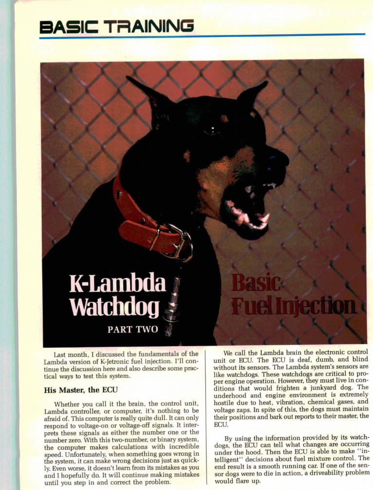
We call the Lambda brain the electronic control
unit or ECU. The ECU is deaf, dumb, and blindwithout its sensors. The Lambda system's sensors are
like watchdogs. These watchdogs are critical to proper engine operation. However, they must live in con
ditions that would frighten a junkyard dog. Theunderhood and engine environment is extremely
hostile due to heat, vibration, chemical gases, andvoltage zaps. In spite of this, the dogs must maintain
their positions and bark out reports to their master, the
ECU.
By using the information provided by its watchdogs, the ECU can tell what changes are occurring
under the hood. Then the ECU is able to make *'intelligent" decisions about fuel mixture control. Theend result is a smooth running car. If one of the sen
sor dogs were to die in action, a driveability problem
would flare up.
Mad Dogs and Technicians
Last month, we discussed the most important
watchdog, the oxygen sensor. But what are the Lamb
da system's other purposeful puppies? Depending
upon the make and model, there are thermal switches,
throttle switches, and vacuum switches. With a little
bit of obedience training, you can learn how to com
mand these dogs to speak. For test purposes, you can
take the commands away from their master, the ECU.The throttle switch dog tells the ECU when the
pedal is to the metal. It does this by grounding the
wire that connects it to the ECU. This wire is usually
connected to ECU pin number 7. On some cars such
as Mercedes-Benz, the throttle switch also grounds a
wire (pin number 6) at idle. When this watchdog dies,
there will be a performance problem at wide-open
throttle (WOT). If the car has a three-pointed star onit, it will also have an off-idle hesitation.
Instead of throttle switches, Peugeot uses vacuum
switch watchdogs. A wire from the ECU is connected
to one side of each vacuum switch. The other side of
the vacuum switch is grounded. The yellow vacuum
switch closes (completes the ground) at about 3.3
inches or more of vacuum. The green vacuum switch
is open above about 3.3 inches of vacuum and closed(grounded) below 3.3 inches.
To test such a vacuum switch, connect a hand-held
vacuum pump to it. Connect an ohmmeter or self-
powered test light across its terminals. Keep an eye on
the meter or the test light. When you apply 3.3 inches
of vacuum to the yellow switch, the meter should show
continuity or the test light should light up. When you
apply 3.3 inches of vacuum to the green switch, themeter reading should change from continuity to open
circuit or infinity. Or, the self-powered light should
go out.
Silicone vapors ruined this oxygen sensor. Careless, ex
cessive use of silicone sprays or certain silicone (RTV)
sealers can cause this. Silicone contamination makes the
sensor send a higher voltage—a false rich signal—to the
ECU.
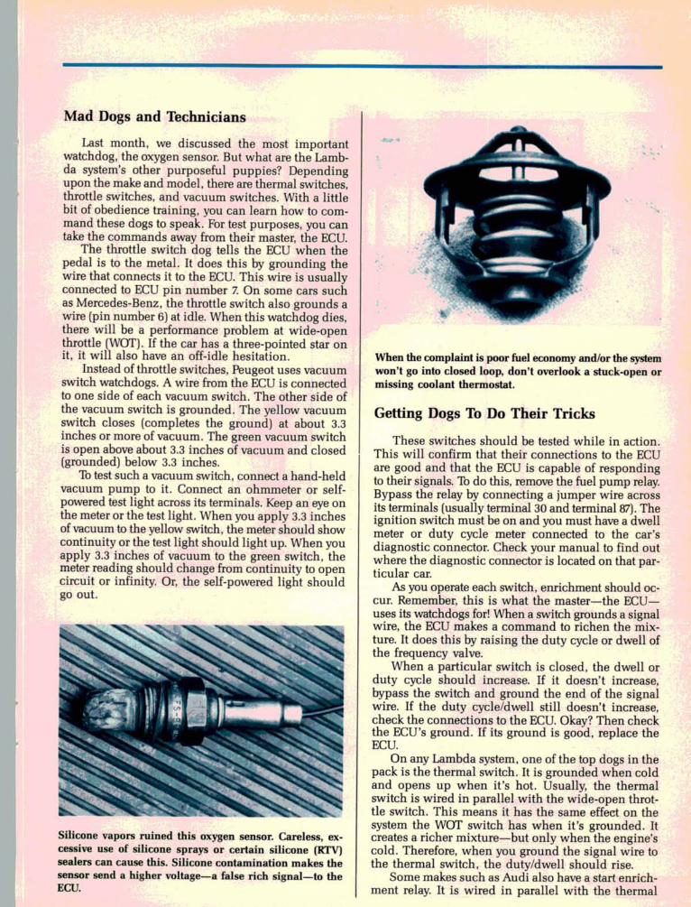
When the complaint is poor fuel economy and/or the system
won't go into closed loop, don't overlook a stuck-open or
missing coolant thermostat.
Getting Dogs To Do Their Tricks
These switches should be tested while in action.
This will confirm that their connections to the ECU
are good and that the ECU is capable of responding
to their signals. To do this, remove the fuel pump relay.
Bypass the relay by connecting a jumper wire across
its terminals (usually terminal 30 and terminal 87). The
ignition switch must be on and you must have a dwell
meter or duty cycle meter connected to the car's
diagnostic connector. Check your manual to find out
where the diagnostic connector is located on that par
ticular car.
As you operate each switch, enrichment should oc
cur. Remember, this is what the master—the ECU—
uses its watchdogs for! When a switch grounds a signal
wire, the ECU makes a command to richen the mix
ture. It does this by raising the duty cycle or dwell of
the frequency valve.
When a particular switch is closed, the dwell or
duty cycle should increase. If it doesn't increase,
bypass the switch and ground the end of the signal
wire. If the duty cycle/dwell still doesn't increase,
check the connections to the ECU. Okay? Then checkthe ECU's ground. If its ground is good, replace the
ECU.
On any Lambda system, one of the top dogs in the
pack is the thermal switch. It is grounded when cold
and opens up when it's hot. Usually, the thermal
switch is wired in parallel with the wide-open throt
tle switch. This means it has the same effect on the
system the WOT switch has when it's grounded. Itcreates a richer mixture—but only when the engine's
cold. Therefore, when you ground the signal wire to
the thermal switch, the duty/dwell should rise.
Some makes such as Audi also have a start enrich
ment relay. It is wired in parallel with the thermal
f
Electronic Control Unit ECU Lambda Relay
-I—
Oxygen Sensor
15 16
Temperature Switch
Fuel Pump Relay
Terminal 87
Frequency Valve
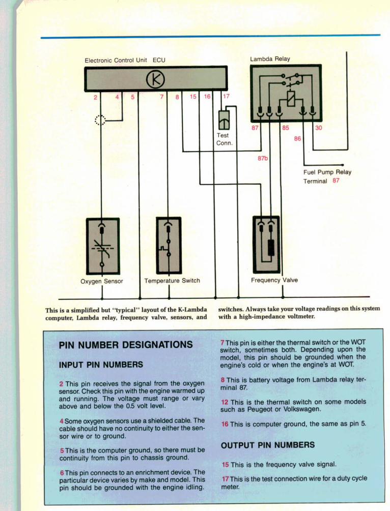
This is a simplified but "typical" layout of the K-Lambda switches. Always take your voltage readings on this system
computer, Lambda relay, frequency valve, sensors, and with a high-impedance voltmeter.
PIN NUMBER DESIGNATIONS
INPUT PIN NUMBERS
2 This pin receives the signal from the oxygen
sensor. Check this pin with the engine warmed up
and running. The voltage must range or vary
above and below the 05 volt level.
4 Some oxygen sensors use a shielded cable. Thecable should have no continuity to either the sen
sor wire or to ground.
5This is the computer ground, so there must be
continuity from this pin to chassis ground.
6 This pin connects to an enrichment device. The
particular device varies by make and model. This
pin should be grounded with the engine idling.
This pin is either the thermal switch or the WOT
switch, sometimes both. Depending upon the
model, this pin should be grounded when the
engine's cold or when the engine's at WOT.
8 This is battery voltage from Lambda relay ter
minal 87.
12 This is the thermal switch on some modelssuch as Peugeot or Volkswagen.
16 This is computer ground, the same as pin 5.
OUTPUT PIN NUMBERS
15 This is the frequency valve signal.
17 This is the test connection wire for a duty cycle
meter.
switch. When you crank the engine, it should makethe duty/dwell rise—even when the engine's hot.
The thermal switch is also important because theLambda system won't go into closed loop until it heats
up and opens its contacts. If the coolant thermostatis missing or stuck open, the system will stay in open
loop and run rich all the time. Before attempting toadjust the mixture, you must verify that the system's
in closed loop operation! You can't tune up a dead dog!
Frequency Valve Freaks
After the watchdogs have barked their signals totheir master, the ECU, the ECU can only command or
control fuel mixture one way. It controls the frequen
cy valve. Last month, we discussed frequency valve
theory and operation. Now I'll tell you how to tell if
the frequency valve died—and more importantly—what killed it.
On the Lambda system, bad connections are themain enemy. The one terminal on the frequency valve
must receive a constant supply of battery positive
voltage. The other terminal must have a good connec
tion to the ECU, because the ECU operates the valveby grounding it.
If there is no power to the frequency valve, check
the Lambda relay first. Check your manual, because
the Lambda relay location varies from car to car. It maybe under the hood, under the dash, or inside a kick
panel! The Lambda relay has two inputs and two out
puts. One input, terminal number 30, is direct battery
positive. The other input, terminal number 86, is from
the fuel pump relay. The fuel pump relay is also
known as the RPM relay. It is powered as soon as the
distributor sends an RPM signal to the fuel pump relay.
The fuel pump relay then feeds battery voltage to theother input of the Lambda relay. Once this happens,
the contacts inside the Lambda relay close and bat
tery voltage goes to the relay's two outputs.
The two outputs of the Lambda relay are:
• relay terminal number 87 to ECU pin number 8;
• terminal number 87b to the frequency valve.
Both should power up at the same instant. If not, trou
ble is afoot! With the engine running, check for power
on both of the number 87 terminals. No power? Check
for power at both inputs, terminals 30 and 86. Also
engine& drive train, electrical-BODY & TRIM. BRAKES* CHASSIS f.
Circle No. Ill on Reader Service Card
verify that you have ground at terminal 85. If you havepower at 30, power at 86, and ground at 85, replace
the Lambda relay.
Remember this detail: if you have power at either
of the the 87 terminals on the relay but not at both of
them, replace the relay.
What if you've only got power at terminal 30? Then
check for power to the warm up regulator or the fre
quency valve. If either of these units has power, thenthere's an open in the wire between the fuel pump
relay and the Lambda relay.
The frequency valve has battery voltage at one of
its terminals, right? You can test for duty cycle with
one of those little test lights that are designed to plug
into a Bosch two-pin fuel injection wiring harness.
Companies such as BWD, Borroughs, Kent-Moore,
OTC, and others offer these fuel injection test lights.Pull the two-wire connector off the frequency valve
and plug the test light into it.
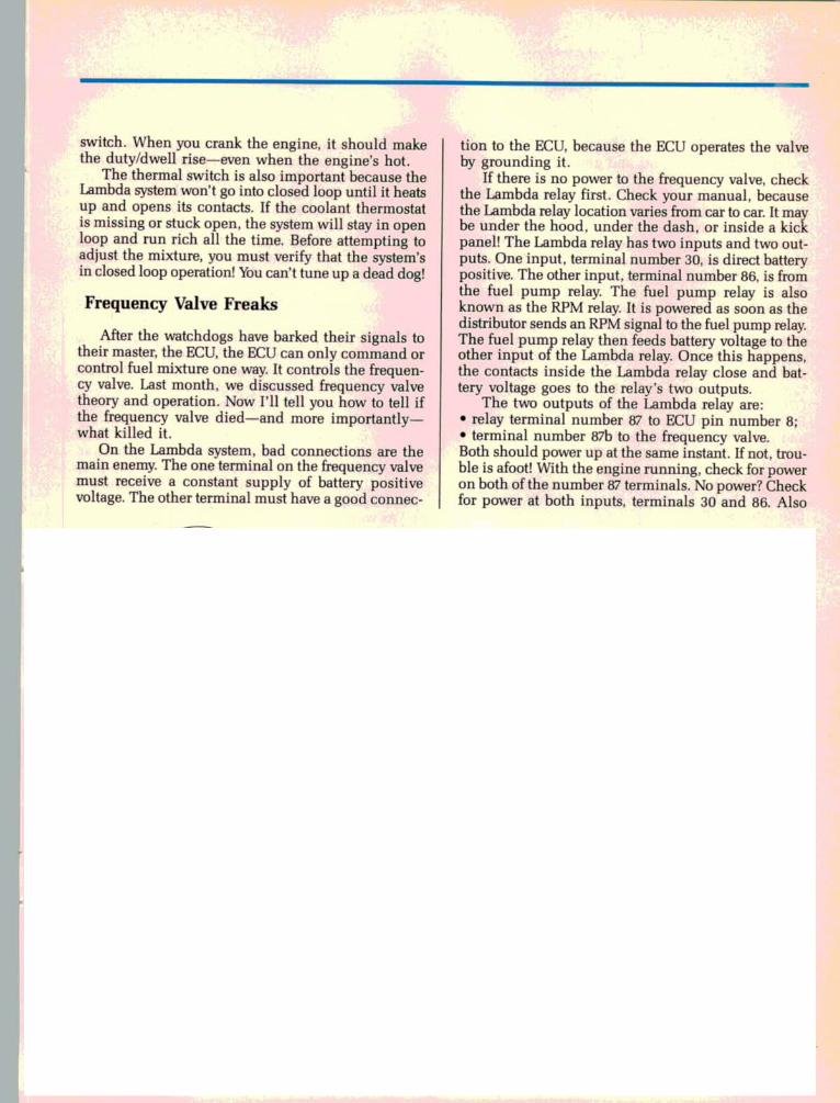
In order to measure K-Lambda duty cycle with your dwell
meter, use an adapter harness such as this Thexton item
(P/N 391) to connect the meter to the frequency valve. Put
the meter on the 90-degree scale. To convert duty to dwell,
multiply duty cycle times 90 percent.
With the engine running, the light should blink
as the ECU makes and breaks the frequency valve's
ground. If the test light doesn't blink, go to the master
himself. Probe ECU terminal number 15 the same way.
No blinks? Then touch the ECU ground terminal,
terminal 16. If the light comes on when you touch ter
minal 16, check for power at terminal 8. Got power at
terminal 8? You do? Then start playing taps, becausethe leader of the pack has died! Replace the ECU.
Brain Teasing
Before you try making friends with unfamiliar and
sometimes angry doggies, you should have a guide of
some kind. Dig out a wiring diagram for the vehicle
you're troubleshooting. One of the best strategies is
to go directly to the multi-pin harness connector forthe ECU and do your dog training there. Testing here
allows you to check everything from the switch/sen
sor doggies back to their master himself, the ECU.
When you take readings at the ECU, be sure to
backprobe the harness. Do not disturb the tightnessof the connectors! These connectors must latch
themselves tightly onto the end board connectors
sticking out of the computer.
Finding Vacuum Leaks
Never try to correct fundamental problems bycranking on the mixture screw. Instead of solving problems, this cover-up approach will only cause fuel
economy and driveability problems.The Germans like to call vacuum leaks or air leaks
false air. This fuel system is so tightly designed that
it really can't cope with this unwanted extra air. Thinkback to our example of the furnace in last month's ar
ticle. Remember how the furnace couldn't keep up
with all the cold air leaking past the shrunken
weatherstripping?
As we emphasized in last month's Basic Training,vacuum leaks are a major contributor to K-Lambda per
formance and driveability problems. When you track
down vacuum leaks, you must be patient and use a
systematic procedure.
First, verify that the problem is lean mixture andnot some mechanical malfunction. The easiest pro
cedure is to move the air flow sensor plate. On updraft
systems, reach under the plate and push up on it. Thismay require separating the mixture control assembly
from its moorings or separating it from the air filter.
On downdraft types, simply push down on the plate.
You only have to move it a little bit! If the rough idle
smooths out, the engine RPM rise slightly, and thehydrocarbon (HC) reading on your infrared analyzer
settles down, you know the engine's extremely lean.
Extremely lean usually means vacuum leaks.The duty cycle is also a good indicator of vacuum
leaks. The bigger the vacuum leak, the higher the duty
cycle reading will be. As you raise engine RPM to 2500,
the duty cycle will become almost normal again. At
2500 RPM, vacuum leaks aren't as pronounced as they
are at idle. However, a mechanical engine problem,
ignition problem, or even a plugged injector is more
likely to show up at both idle and higher RPM. Thistactic is a great way to separate the men from the boys.
As long as you're comparing idle and off-idle
symptoms, remember that a leaking cold start valve
will screw up the CO reading at idle but not at higher
RPM.
Hunting for vacuum leaks with carburetor cleaner
spray is not a good idea because it can damage rub
ber seals. Because carburetor spray is so volatile, it can
make it appear that there's a vacuum leak when there
isn't. It can also soak right through good gaskets. The

best thing to use is a squirt bottle of a much less
volatile substance such as parts-washing solvent.
Liberally spray this on all suspected seals and gaskets.
MANY COMMON SHOP SOLVENTS ARE FLAM
MABLE. IF YOU DECIDE TO USE SOLVENT TO
DETECT VACUUM LEAKS, BE CAREFUL!
For leaks down where the sun don't shine, propane
is very effective. Sometimes you have air leaks in the
duct between the air flow sensor and the intake
manifold. If you discharge some propane under that
duct, it'll find leaks you might otherwise miss. If you
have an old propane enrichment tool that you used
on those dinosaur domestic carburetors, dust it off and
use it to find vacuum leaks.
Whenever you introduce propane or squirt around
with solvent, keep an eye on your infrared exhaust
analyzer. Exhaust analyzers can take as long as 10-20
seconds to respond to the raw HC in the solvent or pro
pane. You should also hear the idle change long before
the infrared responds.
Watch out for small cracks that cause air leaks in the long
plastic duct. This duct connects the air flow sensor to the
throttle valve assembly.
Vacuum Leak Checklist
Here are some common places where you'll prob
ably have to tackle vacuum leaks:
• Injector seals and injector holders. It's a good idea
to replace these o-ring seals every 30,000 miles. Theseseals harden and leak. Those threaded plastic holders
are also nasty leakers. Always coat the new seals/
holders with anti-seize compound.
• Intake manifold gaskets. Intake gasket leaks are a
problem on any car. For added insurance, I like to coat
the gaskets with a copper gasket compound.
• Auxiliary air valve hoses. Give these hoses a tug and
a squeeze. Remember that these hoses can also col
lapse, causing a poor cold idle condition.
• Air flow sensor boot. On updraft models, the boot
may not seal tightly or may have tiny cracks in it.
Remember that if something causes the engine to
backfire, the backfire may blow off this boot. Then the
engine won't start again. If this happens, don't just
reseal the boot. Find out what made the engine
backfire in the first place!
• Cold start valve gasket. Don't laugh! Someone who
was troubleshooting a hard start complaint may have
removed the valve to inspect it. But he didn't notice
its gasket flutter away into never-never land.
• Cracked air duct. This is the long plastic duct that
goes from the air flow sensor to the throttle valve.
• Decel valve hoses. If the system's equipped with a
decel valve, carefully check the valve's hoses forcracks.
• Disconnected full-load enrichment hose. On models
fitted with a full-load enrichment warm up regulator,
the vacuum hose has a nasty habit of coming off down
where you can't see it. Fix this one and you'll slay two
dragons at once—rough idle and a WOT hesitation!
• Other leakers. Other leakers include the dipstick
seal, valve cover gaskets, oil filler cap, EGR valve, crank
seals, brake booster and hoses, and the vacuum ad
vance unit.
Throttle Valve Adjustment Procedure
It never ceases to amaze me that people wouldn't
think about removing the back cover from their $300
color television set and turning an adjustment screw
when the picture is off. But they'll pop open the hoods
on their $15,000 cars and turn adjustment screws! No
problem!
Fortunately, many important adjustment screws are
safely sealed away behind tamper-resistant plugs. But
the throttle valve offers the do-it-yourselfer (DIYer) an
opportunity to really muck things up. Just because he
used to adjust the carburetor on his old car in a similar
manner, he thinks the throttle stop screw is the proper place to adjust idle speed today.
Why would this fellow want to try adjusting the
idle speed? Probably vacuum leaks, that's why! But
this DIYer can't figure out why the idle is still too high
after he's turned the idle speed screw all the way in.
He spies the throttle stop screw, breaks the lock nut
loose, and backs out the stop screw. This allows the
throttle blade to rest against the housing. Instead ofstopping against the screw, the throttle blade now stops
against the soft aluminum throttle housing. Now the
destruction begins!
After cutting away at the soft aluminum for a while,
the throttle blade cuts out enough metal to allow un
wanted air to leak past the blade. Now the idle is too
high again. The car may be in for a tune-up—but the
complaint really is that the idle is too high.
Look for signs of tampering. If the paint seal on
the throttle stop screw is broken, the throttle stop must
be reset. But first, check for and correct the offending
vacuum leaks that started the whole mess in the first
place!
Once you have corrected the vacuum leaks, check
the throttle valve housing for damage. On some
models, you may have to remove the housing in order
to inspect it thoroughly. Check for wallowed-out
throttle shaft bores, too. If the throttle housing is
damaged, you'll have to replace it!
On some models, there's a secondary throttle
blade. Be sure this secondary blade isn't sticking open.
Next, check that the bowden throttle cable moves
freely. Then loosen the lock nut and back out the throt
tle stop screw until it no longer touches the throttle
lever. Turn the screw back in until it just touches the
lever, then turn it in another half turn.
Lock your adjustment with the lock nut. Paint the
nut and screw again so the next technician—it could
be you—knows the job was done correctly.
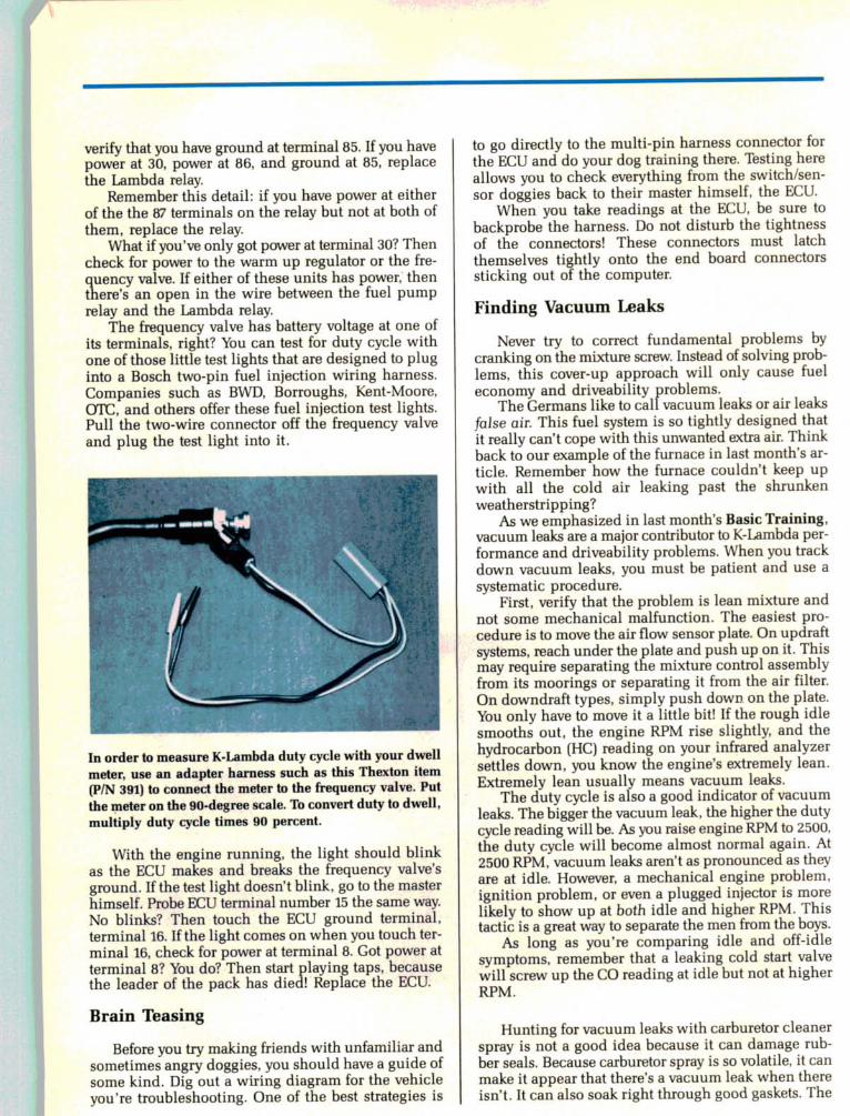
Auxiliary air valve hoses can also crack and cause air leaks.
Remember that if an auxiliary air valve hose collapses, the
engine will tend to stumble and stall when it's cold.
Quick Lambda Check Out Procedure
To give any Lambda system a quick check-out,
follow this procedure:
• Disconnect the oxygen sensor pigtail wire from the
system and connect a high-impedance VOM to the
oxygen sensor. Ground the negative lead of the VOM.
Position the VOM so you can read it easily under the
hood.• Connect a duty cycle meter to the car's test connec
tor or connect a dwell meter to the frequency valve
using the Thexton test harness P/N 391 or an
equivalent adapter.
• Connect an exhaust analyzer to the test port.
• Start the engine and warm it up.
• Grab the disconnected wire that runs from the
oxygen sensor to the ECU with one hand. With the
other hand, grab the negative battery post or a goodground point. The readings should go up on all three
meters. Duty will go up in response to the lean con
dition signalled through your body to the ECU. CO
will go up as the ECU richens the mixture to compen
sate for the lean signal. The VOM connected to the
oxygen sensor will read higher voltage as the oxygen
sensor responds to the richer mixture.
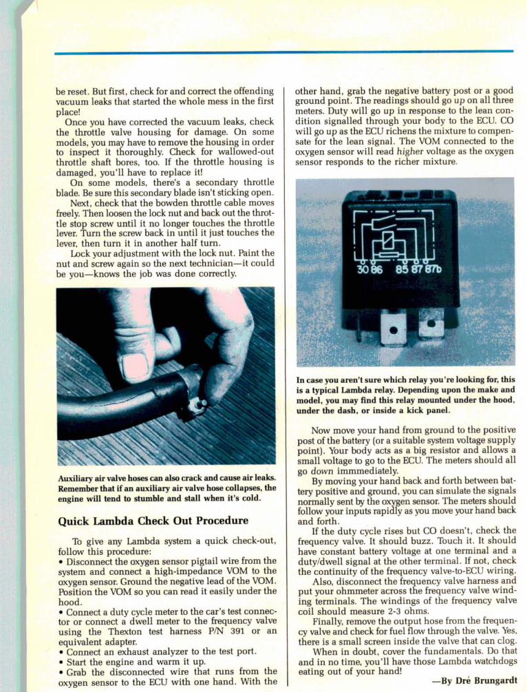
In case you aren't sure which relay you're looking for, this
is a typical Lambda relay. Depending upon the make and
model, you may find this relay mounted under the hood,
under the dash, or inside a kick panel.
Now move your hand from ground to the positive
post of the battery (or a suitable system voltage supply
point). Your body acts as a big resistor and allows a
small voltage to go to the ECU. The meters should all
go down immmediately.
By moving your hand back and forth between bat
tery positive and ground, you can simulate the signals
normally sent by the oxygen sensor. The meters shouldfollow your inputs rapidly as you move your hand back
and forth.
If the duty cycle rises but CO doesn't, check the
frequency valve. It should buzz. Touch it. It should
have constant battery voltage at one terminal and a
duty/dwell signal at the other terminal. If not, checkthe continuity of the frequency valve-to-ECU wiring.
Also, disconnect the frequency valve harness andput your ohmmeter across the frequency valve wind
ing terminals. The windings of the frequency valve
coil should measure 2-3 ohms.
Finally, remove the output hose from the frequen
cy valve and check for fuel flow through the valve. Yes,
there is a small screen inside the valve that can clog.
When in doubt, cover the fundamentals. Do that
and in no time, you'll have those Lambda watchdogseating out of your hand!
—By Dre Brungardt