Embed Size (px)
Citation preview
Basics of ESD and the New Design Sequence
To learn how you can have access to: Discounted Webcasts
Free One-day design workshopsIntensive master stormwater design seminars
Direct On-site technical assistance Self guided web-based learning modules
Visit: www.cwp.org/CBSTP
Agenda1. Why ESD is Important to the Bay
2. The New Design Sequence and Spreadsheet
3. Using Alternative Surfaces and Credits
4. Design of Micro- ESD Practices
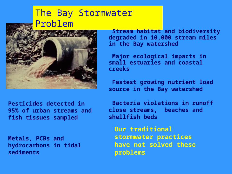
The Bay Stormwater Problem
Stream habitat and biodiversity degraded in 10,000 stream miles in the Bay watershed
Major ecological impacts in small estuaries and coastal creeks
Fastest growing nutrient load source in the Bay watershed
Bacteria violations in runoff close streams, beaches and shellfish beds
Pesticides detected in 95% of urban streams and fish tissues sampled
Metals, PCBs and hydrocarbons in tidal sediments
Our traditional stormwater practices have not solved these problems
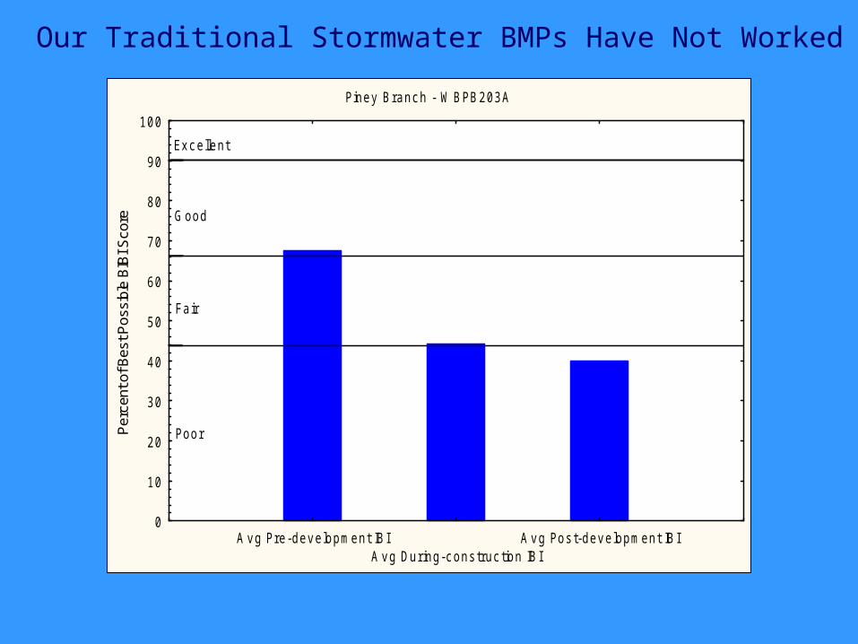
Piney Branc h - W BPB203A
A v g Pre-dev elopment IBIA v g Dur ing-c ons truc tion IBI
A v g Pos t-dev elopment IBI0
10
20
30
40
50
60
70
80
90
100P
erce
nt o
f Bes
t Pos
sibl
e B
IBI S
core
Ex c ellent
Good
Fair
Poor
Our Traditional Stormwater BMPs Have Not Worked
The New Maryland ESD Regulations
You are not alone..tougher stormwater regulations are on the horizon in all Bay states:
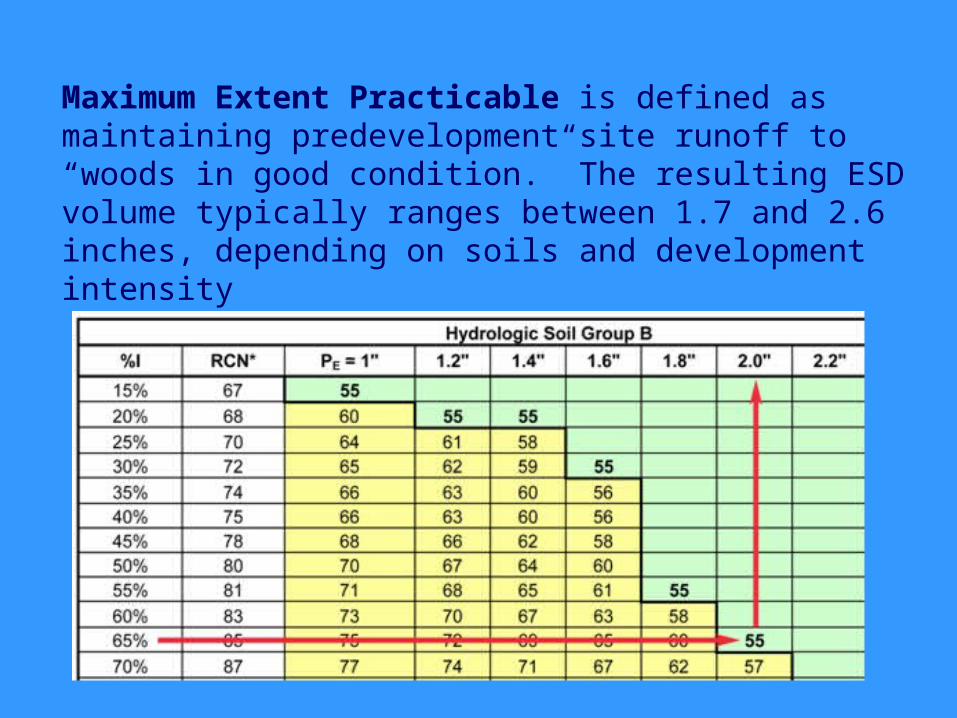
Maximum Extent Practicable is defined as maintaining predevelopment site runoff to “woods in good condition.” The resulting ESD volume typically ranges between 1.7 and 2.6 inches, depending on soils and development intensity
Features of the CSN ESD to MEP Compliance Spreadsheet
Automatically Calculates ESD Target Volume Accounts for all of the credits, alternative
surfaces, micro-ESD practices and conventional practices in a step-wise fashion
Simultaneously tracks ESD volume and Critical Area 10% requirements
Easy to verify compliance
Status of Compliance Spreadsheet
Spreadsheet and Users Guide are available at www.chesapeakestormwater.net
Has undergone significant testing Version 2.0 was released in June, 2010 Version 2.1 released in July 2010
Before You Get Started
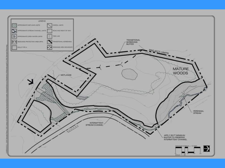
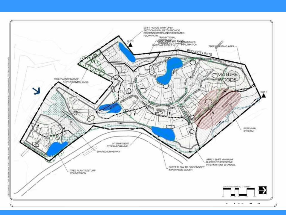
Site Recon (understand the site) Environmental mapping (protected
areas) Define small drainage areas and flow
paths ID locations of most permeable soils Develop site plan that shows impervious
and pervious cover footprints
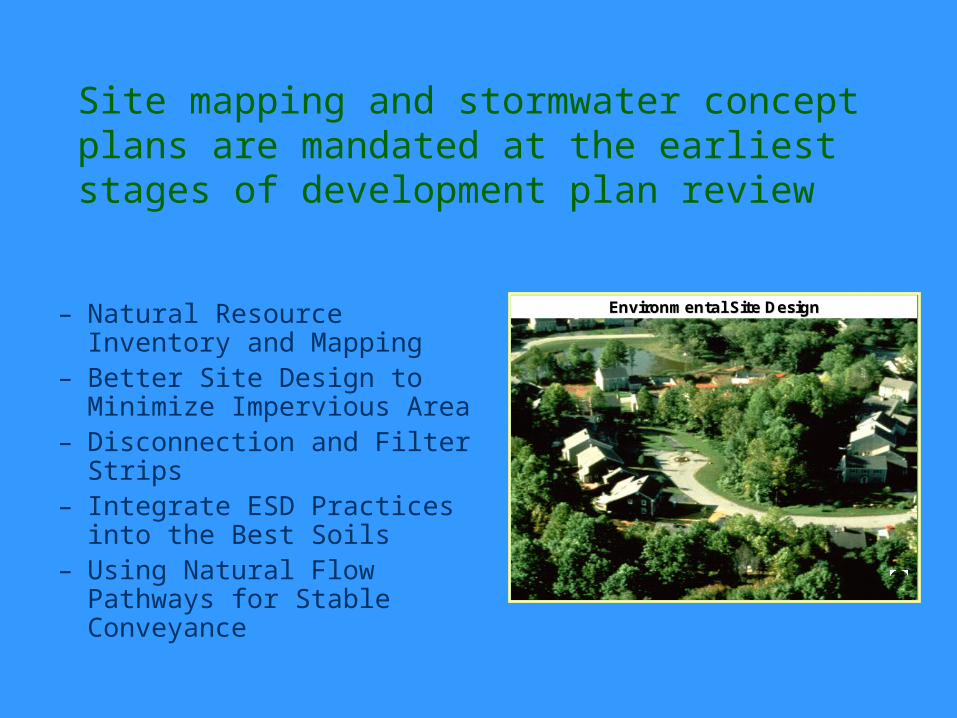
Site mapping and stormwater concept plans are mandated at the earliest stages of development plan review
– Natural Resource Inventory and Mapping
– Better Site Design to Minimize Impervious Area
– Disconnection and Filter Strips
– Integrate ESD Practices into the Best Soils
– Using Natural Flow Pathways for Stable Conveyance
Environmental Site DesignEnvironmental Site Design
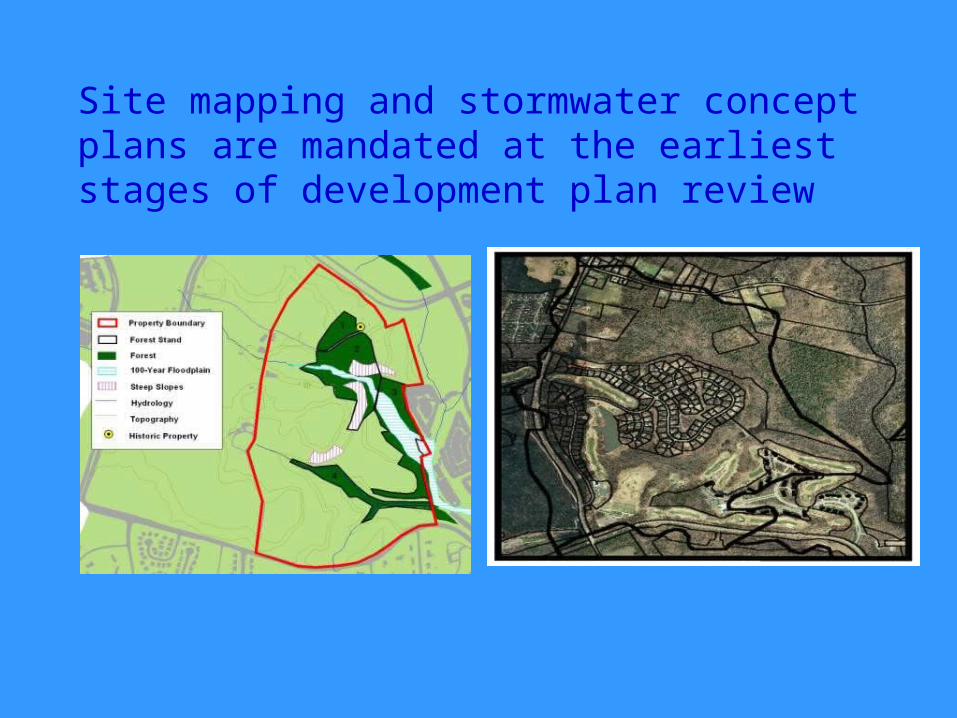
Site mapping and stormwater concept plans are mandated at the earliest stages of development plan review
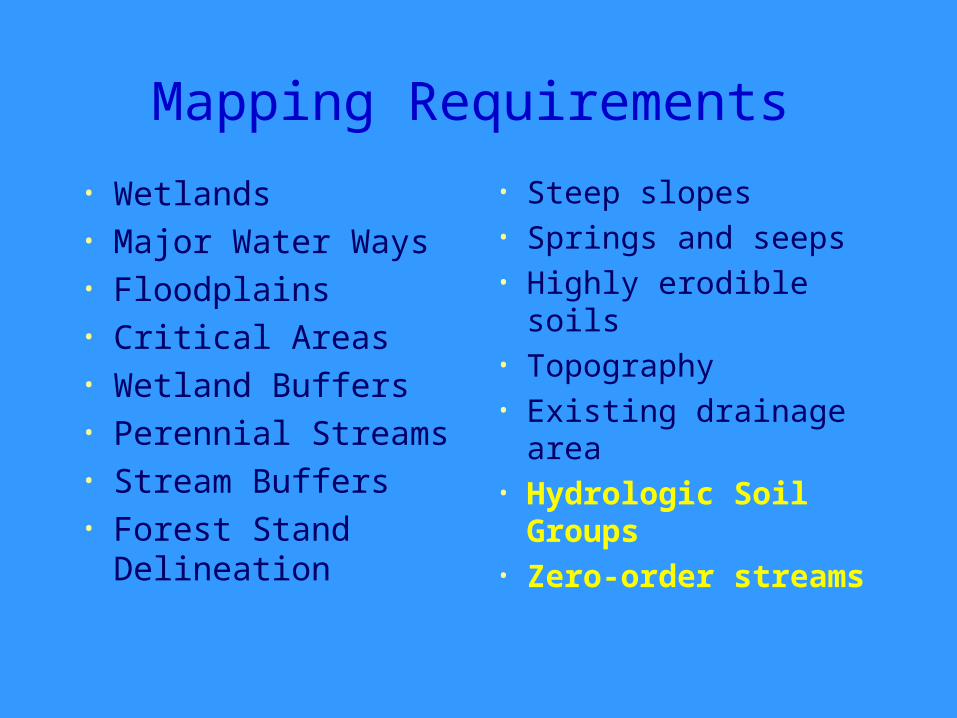
Mapping Requirements
• Wetlands• Major Water Ways• Floodplains• Critical Areas• Wetland Buffers• Perennial Streams• Stream Buffers • Forest Stand
Delineation
• Steep slopes• Springs and seeps• Highly erodible soils• Topography• Existing drainage
area• Hydrologic Soil
Groups• Zero-order streams
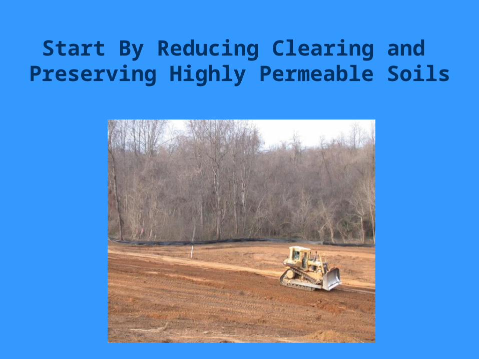
Start By Reducing Clearing and Preserving Highly Permeable Soils
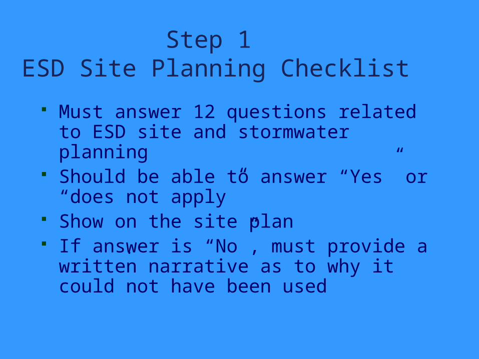
Step 1 ESD Site Planning Checklist
Must answer 12 questions related to ESD site and stormwater planning
Should be able to answer “Yes” or “does not apply”
Show on the site plan If answer is “No”, must provide a
written narrative as to why it could not have been used
.
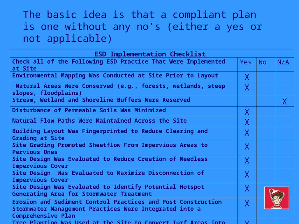
ESD Implementation Checklist Check all of the Following ESD Practice That Were Implemented at Site
Yes No N/A
Environmental Mapping Was Conducted at Site Prior to Layout X Natural Areas Were Conserved (e.g., forests, wetlands, steep slopes, floodplains)
XStream, Wetland and Shoreline Buffers Were Reserved XDisturbance of Permeable Soils Was Minimized XNatural Flow Paths Were Maintained Across the Site XBuilding Layout Was Fingerprinted to Reduce Clearing and Grading at Site
XSite Grading Promoted Sheetflow From Impervious Areas to Pervious Ones
XSite Design Was Evaluated to Reduce Creation of Needless Impervious Cover
XSite Design Was Evaluated to Maximize Disconnection of Impervious Cover
XSite Design Was Evaluated to Identify Potential Hotspot Generating Area for Stormwater Treatment
XErosion and Sediment Control Practices and Post Construction Stormwater Management Practices Were Integrated into a Comprehensive Plan
X
Tree Planting Was Used at the Site to Convert Turf Areas into Forest
X
The basic idea is that a compliant plan is one without any no’s (either a yes or not applicable)
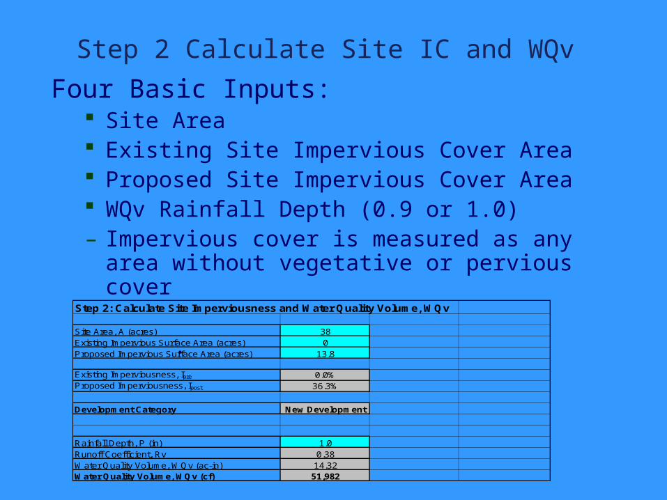
Step 2 Calculate Site IC and WQv
Four Basic Inputs: Site Area Existing Site Impervious Cover Area Proposed Site Impervious Cover Area WQv Rainfall Depth (0.9 or 1.0)– Impervious cover is measured as any area
without vegetative or pervious cover
.
Step 2: Calculate Site Imperviousness and Water Quality Volume, WQv
Site Area, A (acres) 38Existing Impervious Surface Area (acres) 0Proposed Impervious Surface Area (acres) 13.8
Existing Imperviousness, Ipre 0.0%Proposed Imperviousness, Ipost 36.3%
Development Category New Development
Rainfall Depth, P (in) 1.0Runoff Coefficient, Rv 0.38Water Quality Volume, WQv (ac-in) 14.32Water Quality Volume, WQv (cf) 51,982
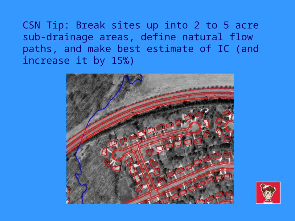
CSN Tip: Break sites up into 2 to 5 acre sub-drainage areas, define natural flow paths, and make best estimate of IC (and increase it by 15%)
Step 3 Compute MD Critical Area Phosphorus Removal Requirement *
Automatically calculates the phosphorus removal requirement, depending on whether the site is classified as new development or redevelopment (>15% IC)
.
* This requirement applies to Intensely Developed Areas in the 1000 ft Critical Area
Step 4 Enter Pre-development Soil Data
Enter Percent Site Area in Hydrologic Soil Group A, B, C or D
Automatically computes ESD rainfall Target Volume, and the Recharge Volume
Your HSGs will determine your ESD strategy.
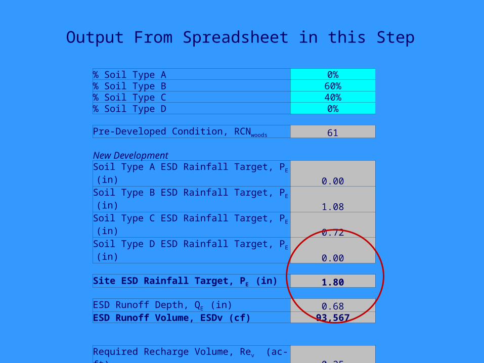
% Soil Type A 0%% Soil Type B 60%% Soil Type C 40%% Soil Type D 0%
Pre-Developed Condition, RCNwoods 61
New DevelopmentSoil Type A ESD Rainfall Target, PE (in) 0.00Soil Type B ESD Rainfall Target, PE (in) 1.08Soil Type C ESD Rainfall Target, PE (in) 0.72Soil Type D ESD Rainfall Target, PE (in) 0.00
Site ESD Rainfall Target, PE (in) 1.80
ESD Runoff Depth, QE (in) 0.68ESD Runoff Volume, ESDv (cf) 93,567
Required Recharge Volume, Rev (ac-ft) 0.25Required Recharge Volume, Rev (cf) 10,812
Output From Spreadsheet in this Step
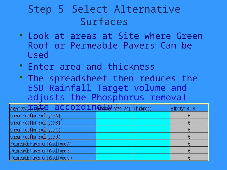
Step 5 Select Alternative Surfaces Look at areas at Site where Green Roof
or Permeable Pavers Can be Used Enter area and thickness The spreadsheet then reduces the ESD
Rainfall Target volume and adjusts the Phosphorus removal rate accordingly
. Alternative Surfaces
Contributing Drainage Area (ac) Thickness Effective RCN
Green Roof (on Soil Type A) 0Green Roof (on Soil Type B) 0Green Roof (on Soil Type C) 0Green Roof (on Soil Type D) 0Permeable Pavement (Soil Type A) 0Permeable Pavement (Soil Type B) 0Permeable Pavement (Soil Type C) 0
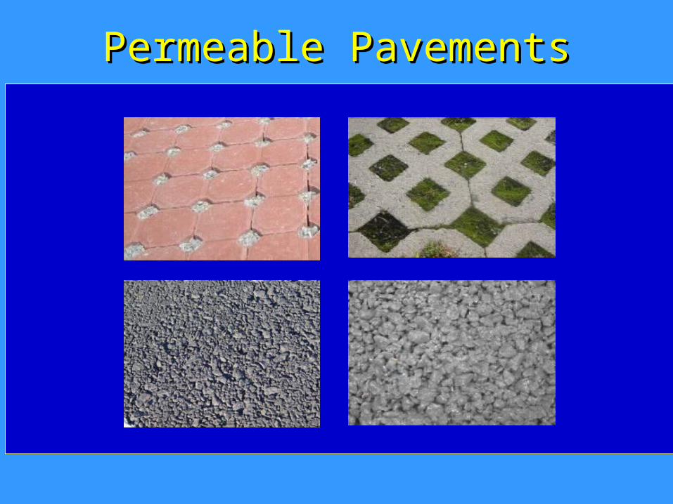
Permeable PavementsPermeable Pavements
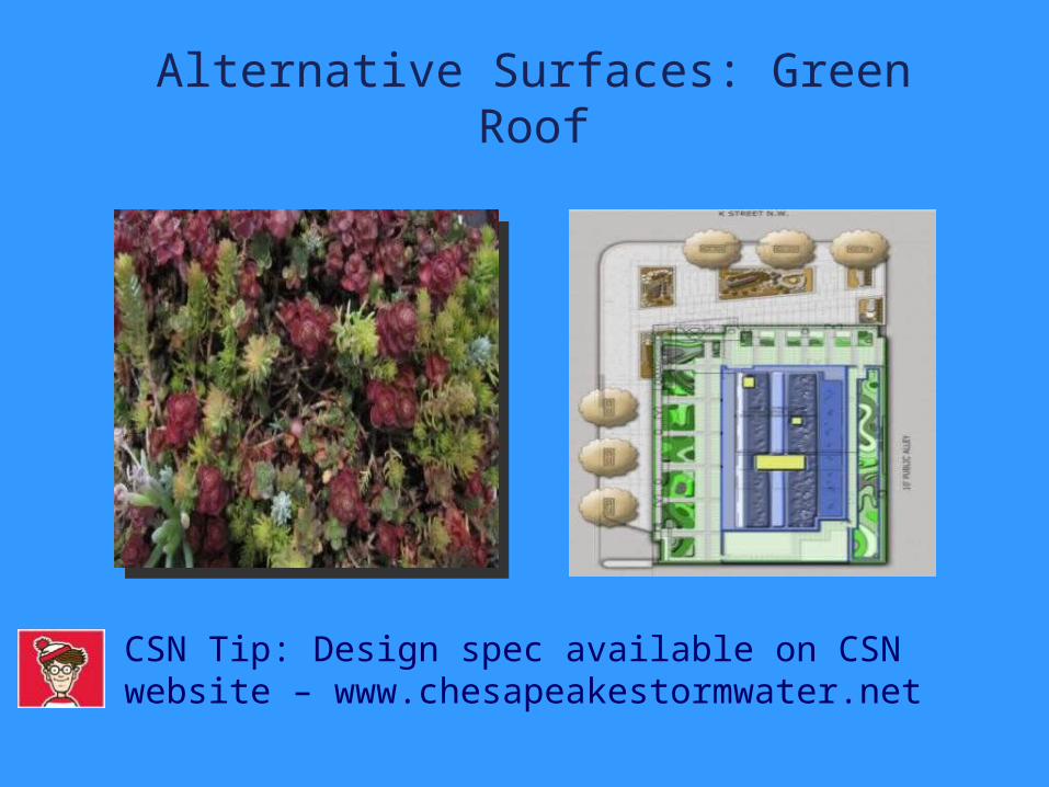
Alternative Surfaces: Green Roof
CSN Tip: Design spec available on CSN website – www.chesapeakestormwater.net
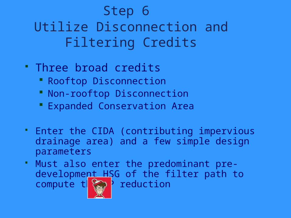
Step 6 Utilize Disconnection and Filtering
Credits
Three broad credits Rooftop Disconnection Non-rooftop Disconnection Expanded Conservation Area
Enter the CIDA (contributing impervious drainage area) and a few simple design parameters
Must also enter the predominant pre-development HSG of the filter path to compute the TP reduction
.

Step 6: Select Nonstructural Practices to Treat the ESD Rainfall Target
Nonstructural Practices PE Credit Description
Contributing Impervious Cover (ac)
Direct ESDv Received by Practice (cf)
ESDv from
Upstream Practices
(cf)Practice Specific
Parameter(s)
PE
Credit (in)
ESDv credit (cf)
Runoff Volume Remaining (cf)
Enhanced Filter Volume
(cf)Rev (cf)
Disconnection of Rooftop Runoff (A/B Soils)
Up to 1 inch credit provided based upon disconnection flow
length. 3 18,622 0
Flow Path (ft) East/West
1 10,346 8,276 10,34675Western Shore
Disconnection of Rooftop Runoff (C/D Soils)
Up to 1 inch credit provided based upon disconnection flow
length. 0 0 0 0 0 0
Disconnection of Non-Rooftop Runoff (A/B Soils)
Up to 1 inch credit provided based upon
disconnection and contributing flow
lengths. 0 0
Disconnection Length (ft)
Contributing Length (ft)
(Impervious)
0.4 0 0 075 150
Disconnection of Non-Rooftop Runoff (C/D Soils)
Up to 1 inch credit provided based upon
disconnection and contributing flow
lengths. 0 0 0 0 0 0
Sheetflow to Conservation Areas (A/B Soils)
Up to 1 inch credit provided based upon
conservation area width. 0 13437
Minimum Width (ft)
1 7,465 -7,465 7,465100
CSN Tip: Connect CIDA “blobs” with pervious “blobs” on plan and check distances/slopes. OK to aggregate acceptable credits in the spreadsheet
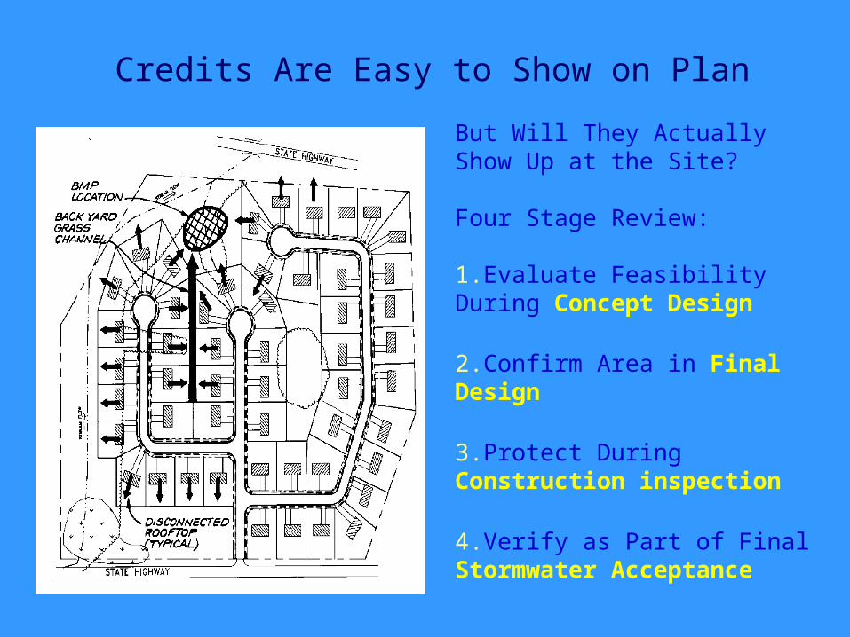
Credits Are Easy to Show on Plan
But Will They Actually Show Up at the Site?
Four Stage Review:
1.Evaluate Feasibility During Concept Design
2.Confirm Area in Final Design
3.Protect During Construction inspection
4.Verify as Part of Final Stormwater Acceptance
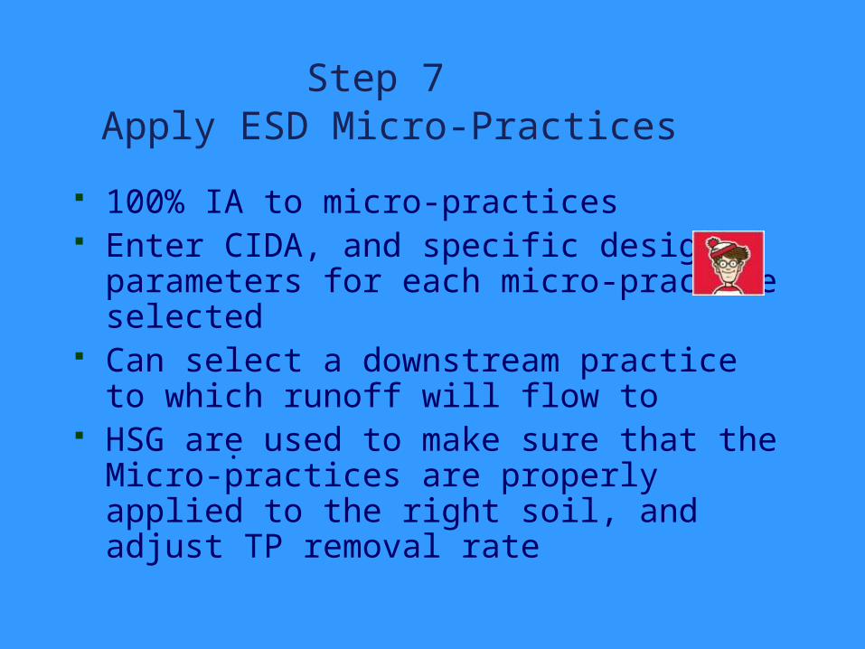
Step 7 Apply ESD Micro-Practices
100% IA to micro-practices Enter CIDA, and specific design
parameters for each micro-practice selected
Can select a downstream practice to which runoff will flow to
HSG are used to make sure that the Micro-practices are properly applied to the right soil, and adjust TP removal rate
.
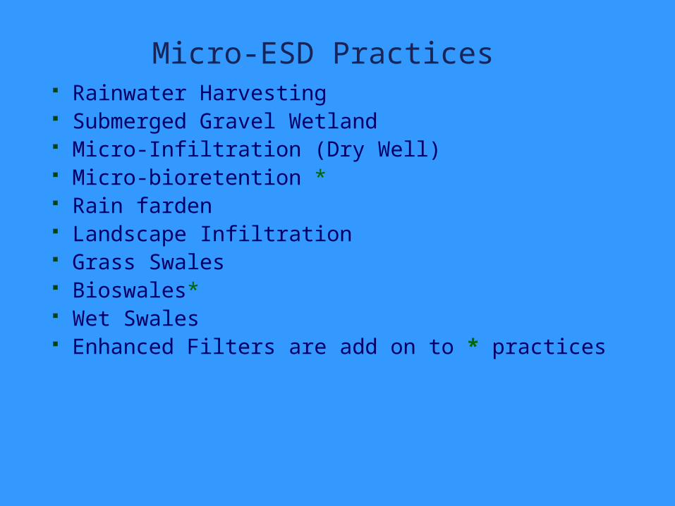
Micro-ESD Practices Rainwater Harvesting Submerged Gravel Wetland Micro-Infiltration (Dry Well) Micro-bioretention * Rain farden Landscape Infiltration Grass Swales Bioswales* Wet Swales Enhanced Filters are add on to * practices
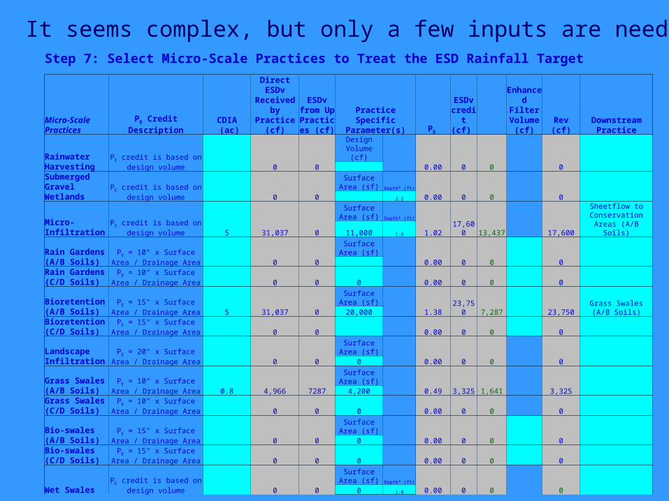
Step 7: Select Micro-Scale Practices to Treat the ESD Rainfall Target
Micro-Scale Practices PE Credit Description
CDIA (ac)
Direct ESDv Received
by Practice (cf)
ESDv from UpPractice
s (cf)Practice Specific
Parameter(s) PE
ESDv credit (cf)
Enhanced Filter Volume
(cf) Rev (cf)Downstream
Practice
Rainwater Harvesting
PE credit is based on design volume 0 0
Design Volume (cf)
0.00 0 0 0 Submerged Gravel Wetlands
PE credit is based on design volume 0 0
Surface Area (sf) Depth* (ft)
0.00 0 0 0 2.2
Micro-Infiltration
PE credit is based on design volume 5 31,037 0
Surface Area (sf) Depth* (ft)
1.02 17,600 13,437 17,600
Sheetflow to Conservation Areas
(A/B Soils)11,000 1.6
Rain Gardens (A/B Soils)
PE = 10" x Surface Area / Drainage Area 0 0
Surface Area (sf)
0.00 0 0 0 Rain Gardens (C/D Soils)
PE = 10" x Surface Area / Drainage Area 0 0 0 0.00 0 0 0
Bioretention (A/B Soils)
PE = 15" x Surface Area / Drainage Area 5 31,037 0
Surface Area (sf)
1.38 23,750 7,287 23,750Grass Swales (A/B
Soils)20,000Bioretention (C/D Soils)
PE = 15" x Surface Area / Drainage Area 0 0 0.00 0 0 0
Landscape Infiltration
PE = 20" x Surface Area / Drainage Area 0 0
Surface Area (sf)
0.00 0 0 0 0
Grass Swales (A/B Soils)
PE = 10" x Surface Area / Drainage Area 0.8 4,966 7287
Surface Area (sf)
0.49 3,325 1,641 3,325 4,200Grass Swales (C/D Soils)
PE = 10" x Surface Area / Drainage Area 0 0 0 0.00 0 0 0
Bio-swales (A/B Soils)
PE = 15" x Surface Area / Drainage Area 0 0
Surface Area (sf)
0.00 0 0 0 0Bio-swales (C/D Soils)
PE = 15" x Surface Area / Drainage Area 0 0 0 0.00 0 0 0
Wet SwalesPE credit is based on design
volume 0 0
Surface Area (sf) Depth* (ft)
0.00 0 0 0 0 1.0
It seems complex, but only a few inputs are needed
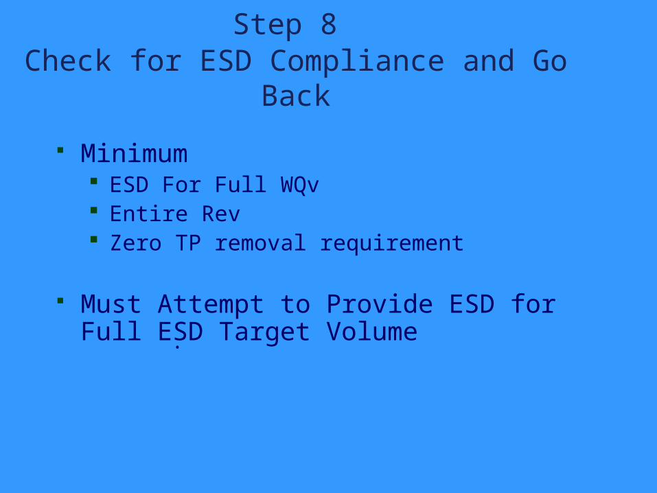
Step 8 Check for ESD Compliance and Go
Back
Minimum ESD For Full WQv Entire Rev Zero TP removal requirement
Must Attempt to Provide ESD for Full ESD Target Volume .
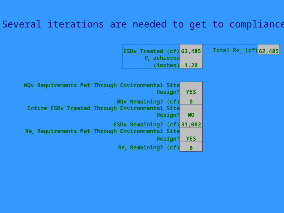
ESDv Treated (cf) 62,485 Total Rev (cf) 62,485
PE achieved (inches) 1.20
WQv Requirements Met Through Environmental Site Design? YES
WQv Remaining? (cf) 0
Entire ESDv Treated Through Environmental Site Design? NO
ESDv Remaining? (cf) 31,082
Rev Requirements Met Through Environmental Site Design? YES
Rev Remaining? (cf) 0
Several iterations are needed to get to compliance
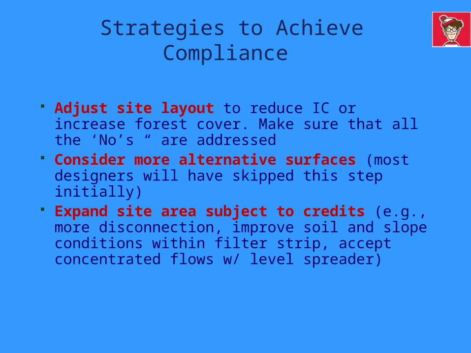
Strategies to Achieve Compliance
Adjust site layout to reduce IC or increase forest cover. Make sure that all the ‘No’s “ are addressed
Consider more alternative surfaces (most designers will have skipped this step initially)
Expand site area subject to credits (e.g., more disconnection, improve soil and slope conditions within filter strip, accept concentrated flows w/ level spreader)
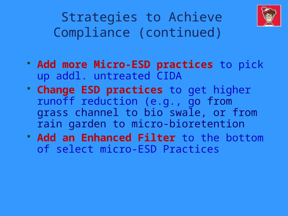
Strategies to Achieve Compliance (continued)
Add more Micro-ESD practices to pick up addl. untreated CIDA
Change ESD practices to get higher runoff reduction (e.g., go from grass channel to bio swale, or from rain garden to micro-bioretention
Add an Enhanced Filter to the bottom of select micro-ESD Practices
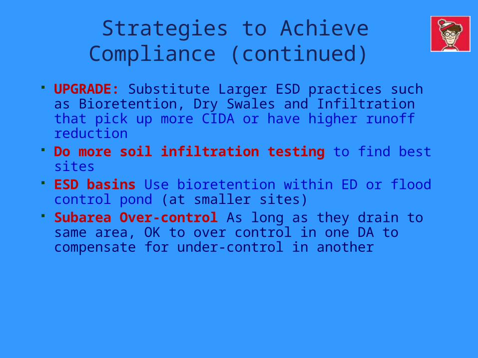
Strategies to Achieve Compliance (continued)
UPGRADE: Substitute Larger ESD practices such as Bioretention, Dry Swales and Infiltration that pick up more CIDA or have higher runoff reduction
Do more soil infiltration testing to find best sites
ESD basins Use bioretention within ED or flood control pond (at smaller sites)
Subarea Over-control As long as they drain to same area, OK to over control in one DA to compensate for under-control in another
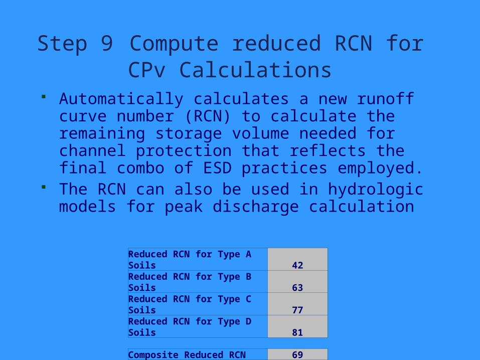
Step 9 Compute reduced RCN for CPv Calculations
Automatically calculates a new runoff curve number (RCN) to calculate the remaining storage volume needed for channel protection that reflects the final combo of ESD practices employed.
The RCN can also be used in hydrologic models for peak discharge calculation
. Reduced RCN for Type A Soils 42Reduced RCN for Type B Soils 63Reduced RCN for Type C Soils 77Reduced RCN for Type D Soils 81
Composite Reduced RCN 69
Q (in) 0.45CPv Treatment Required (cf) 62,511
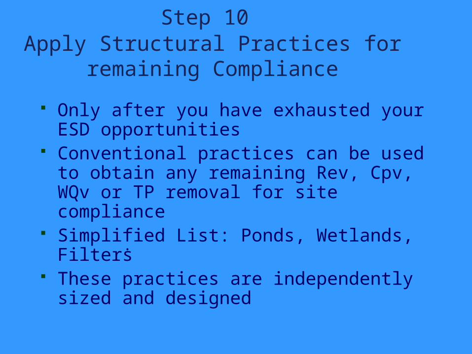
Step 10 Apply Structural Practices for
remaining Compliance
Only after you have exhausted your ESD opportunities
Conventional practices can be used to obtain any remaining Rev, Cpv, WQv or TP removal for site compliance
Simplified List: Ponds, Wetlands, Filters These practices are independently sized
and designed .
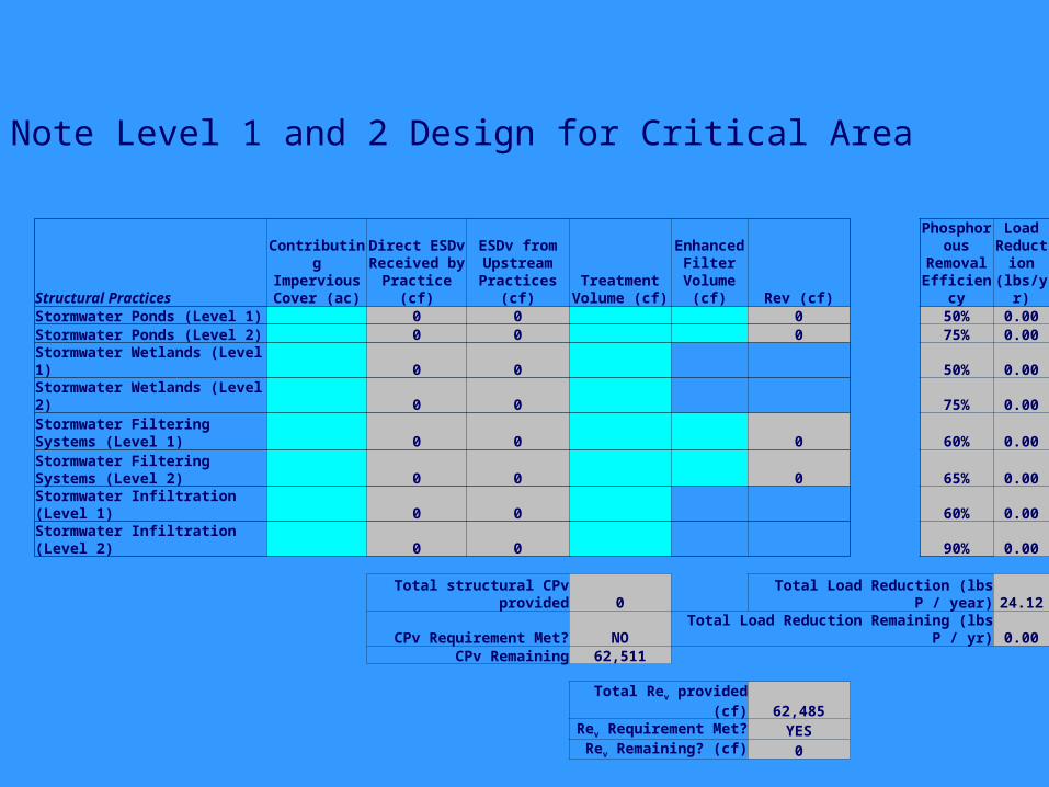
Structural Practices
Contributing Impervious Cover (ac)
Direct ESDv Received by Practice (cf)
ESDv from Upstream
Practices (cf)Treatment
Volume (cf)
Enhanced Filter
Volume (cf) Rev (cf)
Phosphorous
Removal Efficiency
Load Reducti
on (lbs/yr)
Stormwater Ponds (Level 1) 0 0 0 50% 0.00Stormwater Ponds (Level 2) 0 0 0 75% 0.00Stormwater Wetlands (Level 1) 0 0 50% 0.00Stormwater Wetlands (Level 2) 0 0 75% 0.00Stormwater Filtering Systems (Level 1) 0 0 0 60% 0.00Stormwater Filtering Systems (Level 2) 0 0 0 65% 0.00Stormwater Infiltration (Level 1) 0 0 60% 0.00Stormwater Infiltration (Level 2) 0 0 90% 0.00
Total structural CPv provided 0 Total Load Reduction (lbs P / year) 24.12
CPv Requirement Met? NO Total Load Reduction Remaining (lbs P / yr) 0.00CPv Remaining 62,511
Total Rev provided (cf) 62,485Rev Requirement Met? YES
Rev Remaining? (cf) 0
Note Level 1 and 2 Design for Critical Area
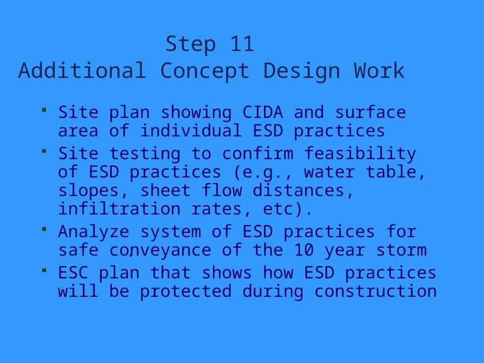
Step 11 Additional Concept Design Work
Site plan showing CIDA and surface area of individual ESD practices
Site testing to confirm feasibility of ESD practices (e.g., water table, slopes, sheet flow distances, infiltration rates, etc).
Analyze system of ESD practices for safe conveyance of the 10 year storm
ESC plan that shows how ESD practices will be protected during construction
.
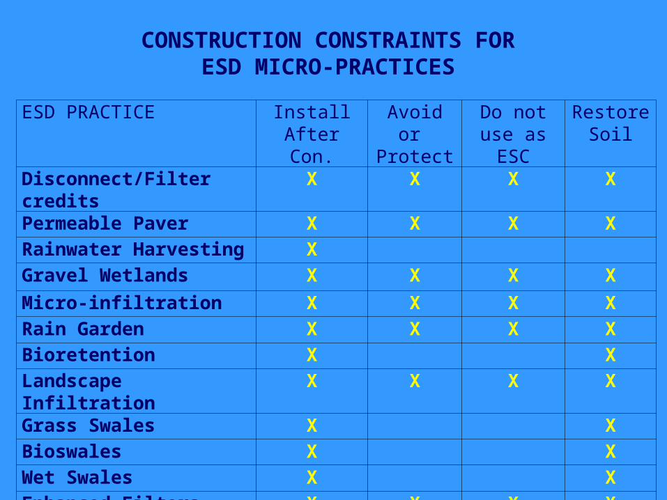
ESD PRACTICE InstallAfter Con.
Avoid or Protect
Do not use as ESC
Restore Soil
Disconnect/Filter credits
X X X X
Permeable Paver X X X XRainwater Harvesting XGravel Wetlands X X X XMicro-infiltration X X X XRain Garden X X X XBioretention X XLandscape Infiltration
X X X X
Grass Swales X XBioswales X XWet Swales X XEnhanced Filters X X X X
CONSTRUCTION CONSTRAINTS FORESD MICRO-PRACTICES
Solution: Rain gardens or rainwater harvesting
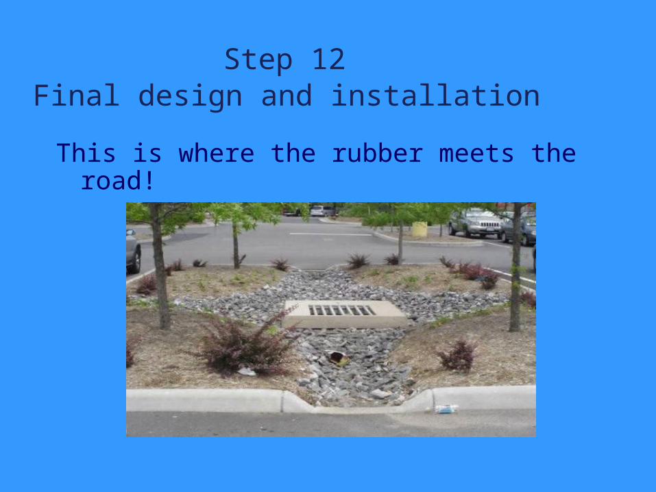
Step 12 Final design and installation
This is where the rubber meets the road!
.

Alternative Surfaces and Credits
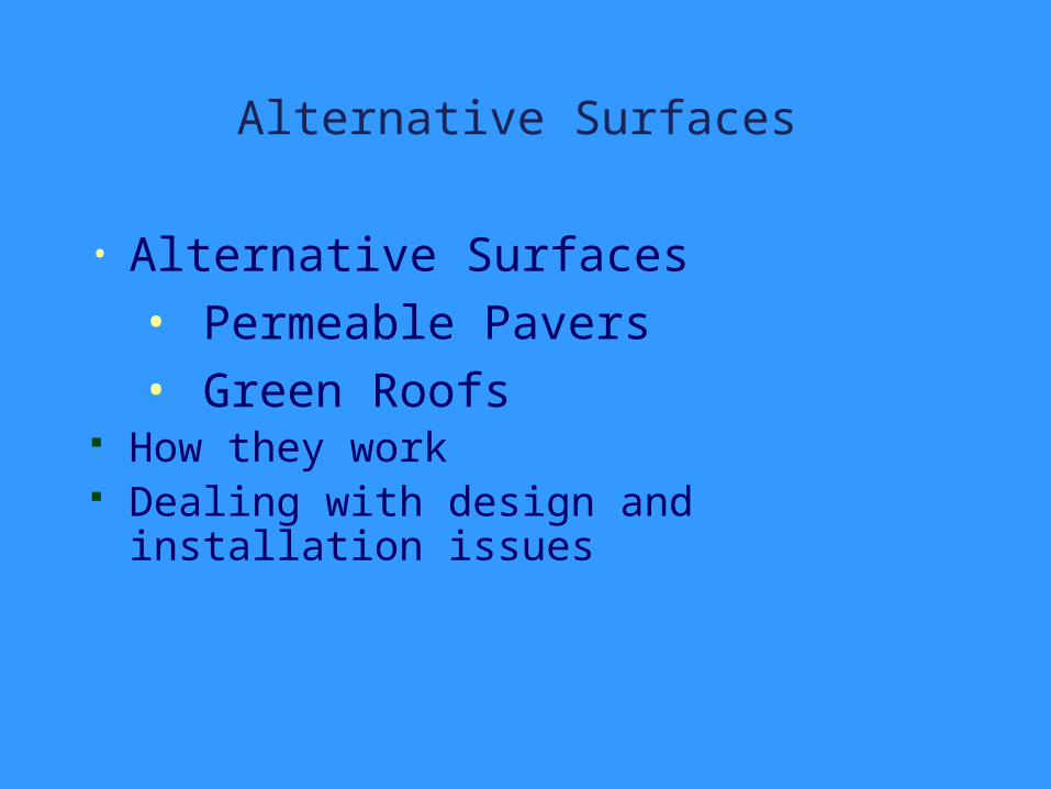
Alternative Surfaces
• Alternative Surfaces • Permeable Pavers• Green Roofs
How they work Dealing with design and installation
issues
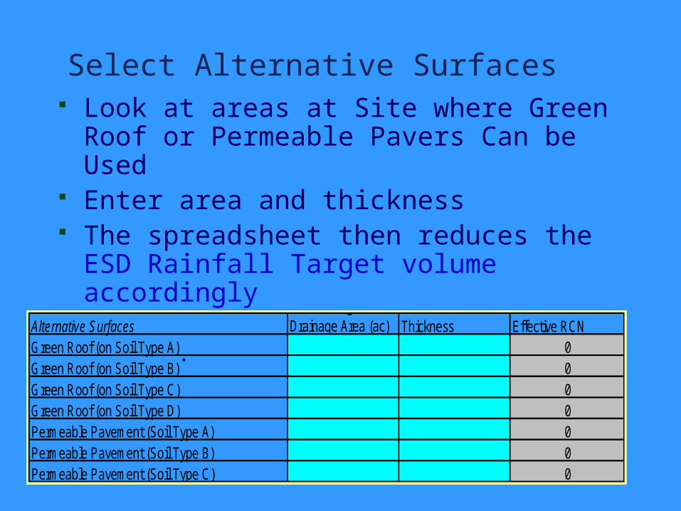
Select Alternative Surfaces Look at areas at Site where Green Roof
or Permeable Pavers Can be Used Enter area and thickness The spreadsheet then reduces the ESD
Rainfall Target volume accordingly
. Alternative Surfaces
Contributing Drainage Area (ac) Thickness Effective RCN
Green Roof (on Soil Type A) 0Green Roof (on Soil Type B) 0Green Roof (on Soil Type C) 0Green Roof (on Soil Type D) 0Permeable Pavement (Soil Type A) 0Permeable Pavement (Soil Type B) 0Permeable Pavement (Soil Type C) 0
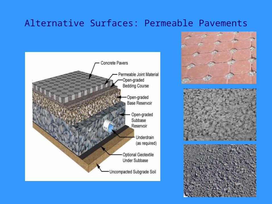
Alternative Surfaces: Permeable Pavements
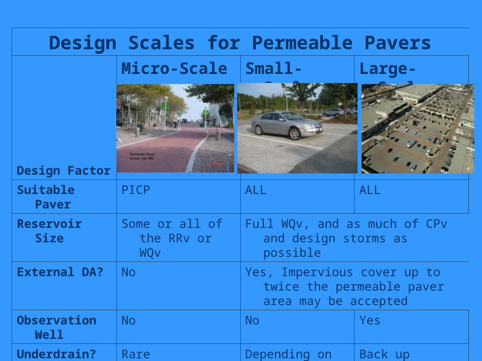
Design Scales for Permeable Pavers
Design Factor
Micro-Scale Small-Scale
Large-Scale
Suitable Paver
PICP ALL ALL
Reservoir Size
Some or all of the RRv or WQv
Full WQv, and as much of CPv and design storms as possible
External DA? No Yes, Impervious cover up to twice the permeable paver area may be accepted
Observation Well
No No Yes
Underdrain? Rare Depending on soils
Back up underdrain
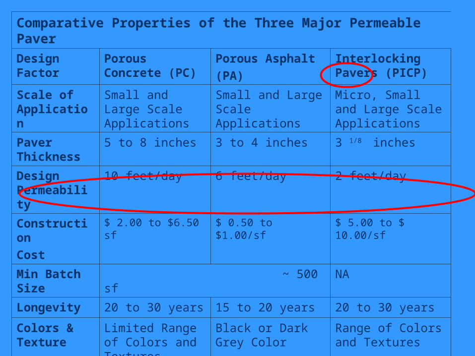
Comparative Properties of the Three Major Permeable Paver
Design Factor
Porous Concrete (PC)
Porous Asphalt (PA)
Interlocking Pavers (PICP)
Scale of Application
Small and Large Scale Applications
Small and Large Scale Applications
Micro, Small and Large Scale Applications
Paver Thickness
5 to 8 inches 3 to 4 inches 3 1/8 inches
Design Permeability
10 feet/day 6 feet/day 2 feet/day
ConstructionCost
$ 2.00 to $6.50 sf $ 0.50 to $1.00/sf $ 5.00 to $ 10.00/sf
Min Batch Size
~ 500 sf NA
Longevity 20 to 30 years 15 to 20 years 20 to 30 years
Colors & Texture
Limited Range of Colors and Textures
Black or Dark Grey Color
Range of Colors and Textures
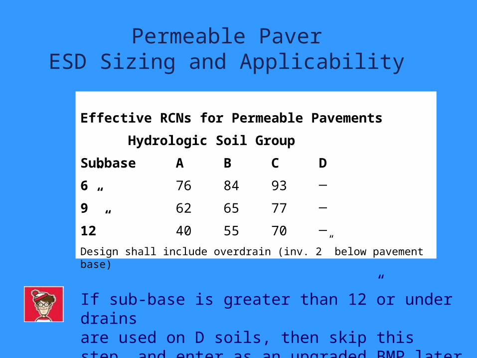
Permeable PaverESD Sizing and Applicability
Effective RCNs for Permeable Pavements
Hydrologic Soil Group
Subbase A B C D
6” 76 84 93 ─
9” 62 65 77 ─
12” 40 55 70 ─
Design shall include overdrain (inv. 2” below pavement base)
If sub-base is greater than 12”or under drains are used on D soils, then skip this step, and enter as an upgraded BMP later on
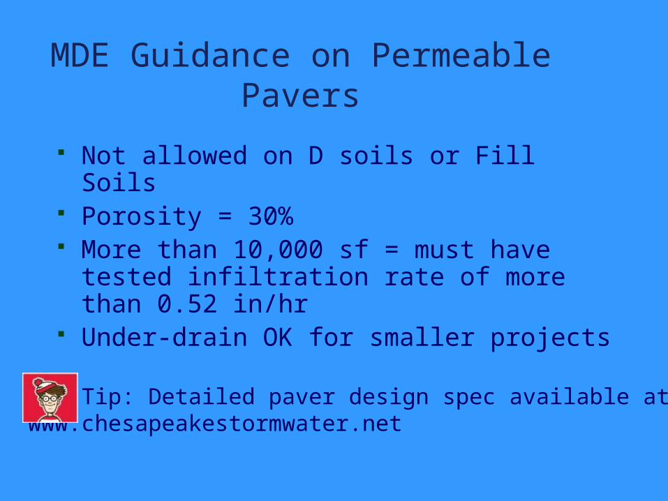
MDE Guidance on Permeable Pavers
Not allowed on D soils or Fill Soils Porosity = 30% More than 10,000 sf = must have tested
infiltration rate of more than 0.52 in/hr Under-drain OK for smaller projects
CSN Tip: Detailed paver design spec available atwww.chesapeakestormwater.net
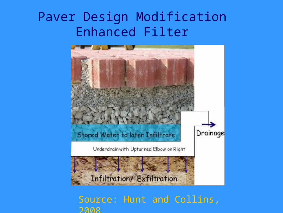
Paver Design ModificationEnhanced Filter
Source: Hunt and Collins, 2008
Enhanced Filters The stone reservoir volume is equal to
the surface area multiplied by depth divided by the porosity (n) of the stone
Used to address Rev for the contributing impervious area using the percent volume method.
When coupled with other properly designed structural or micro-scale practices, the combined system will address the ESD sizing criteria.
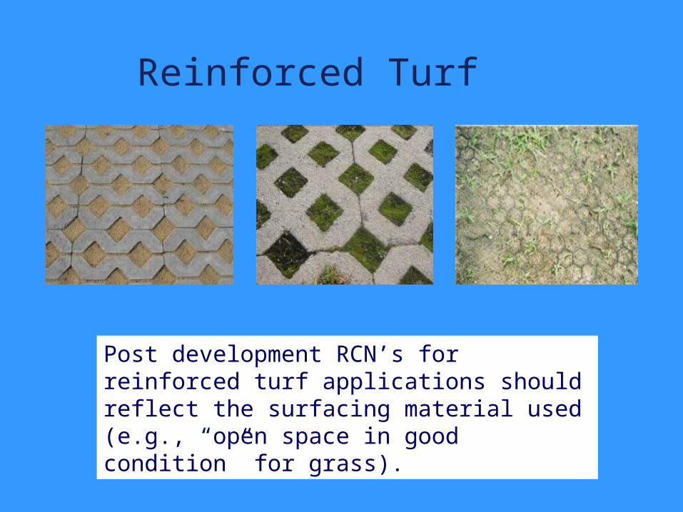
Reinforced Turf
Post development RCN’s for reinforced turf applications should reflect the surfacing material used (e.g., “open space in good condition” for grass).
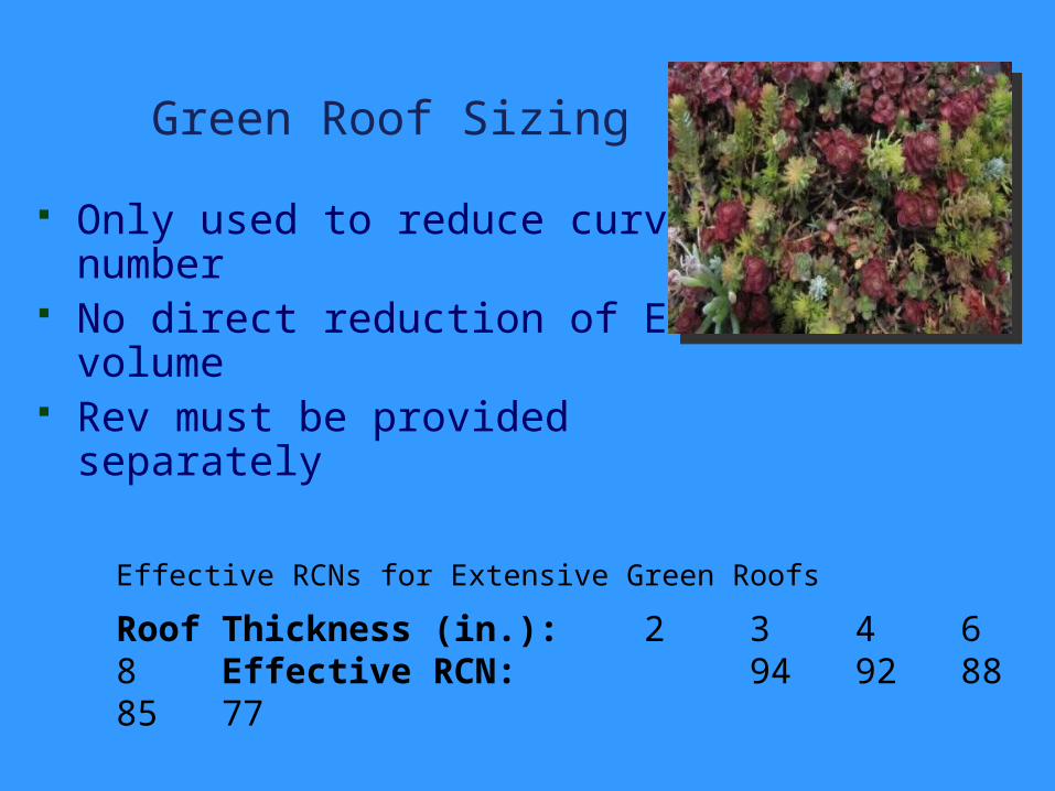
Green Roof Sizing
Only used to reduce curve number
No direct reduction of ESD volume
Rev must be provided separately
Effective RCNs for Extensive Green Roofs
Roof Thickness (in.): 2 3 4 6 8 Effective RCN: 94 92 88 85 77
Disconnection and Filtering Credits
Three broad credits Rooftop Disconnection Non-rooftop Disconnection Expanded Conservation Area
Enter the CIDA (contributing impervious drainage area) and a few simple design parameters
Must also enter the predominant pre-development HSG of the filter path to compute the TP reduction
.
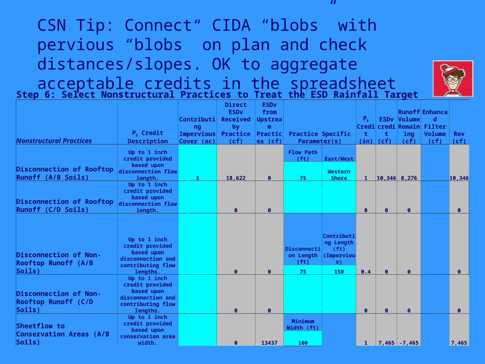
Step 6: Select Nonstructural Practices to Treat the ESD Rainfall Target
Nonstructural Practices PE Credit Description
Contributing Impervious Cover (ac)
Direct ESDv Received by Practice (cf)
ESDv from
Upstream Practices
(cf)Practice Specific
Parameter(s)
PE
Credit (in)
ESDv credit (cf)
Runoff Volume Remaining (cf)
Enhanced Filter Volume
(cf)Rev (cf)
Disconnection of Rooftop Runoff (A/B Soils)
Up to 1 inch credit provided based upon disconnection flow
length. 3 18,622 0
Flow Path (ft) East/West
1 10,346 8,276 10,34675Western Shore
Disconnection of Rooftop Runoff (C/D Soils)
Up to 1 inch credit provided based upon disconnection flow
length. 0 0 0 0 0 0
Disconnection of Non-Rooftop Runoff (A/B Soils)
Up to 1 inch credit provided based upon
disconnection and contributing flow
lengths. 0 0
Disconnection Length (ft)
Contributing Length (ft)
(Impervious)
0.4 0 0 075 150
Disconnection of Non-Rooftop Runoff (C/D Soils)
Up to 1 inch credit provided based upon
disconnection and contributing flow
lengths. 0 0 0 0 0 0
Sheetflow to Conservation Areas (A/B Soils)
Up to 1 inch credit provided based upon
conservation area width. 0 13437
Minimum Width (ft)
1 7,465 -7,465 7,465100
CSN Tip: Connect CIDA “blobs” with pervious “blobs” on plan and check distances/slopes. OK to aggregate acceptable credits in the spreadsheet
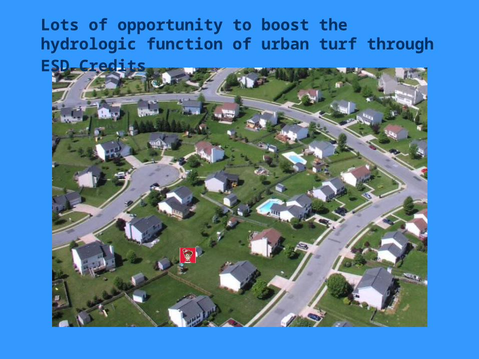
Lots of opportunity to boost the hydrologic function of urban turf through ESD Credits
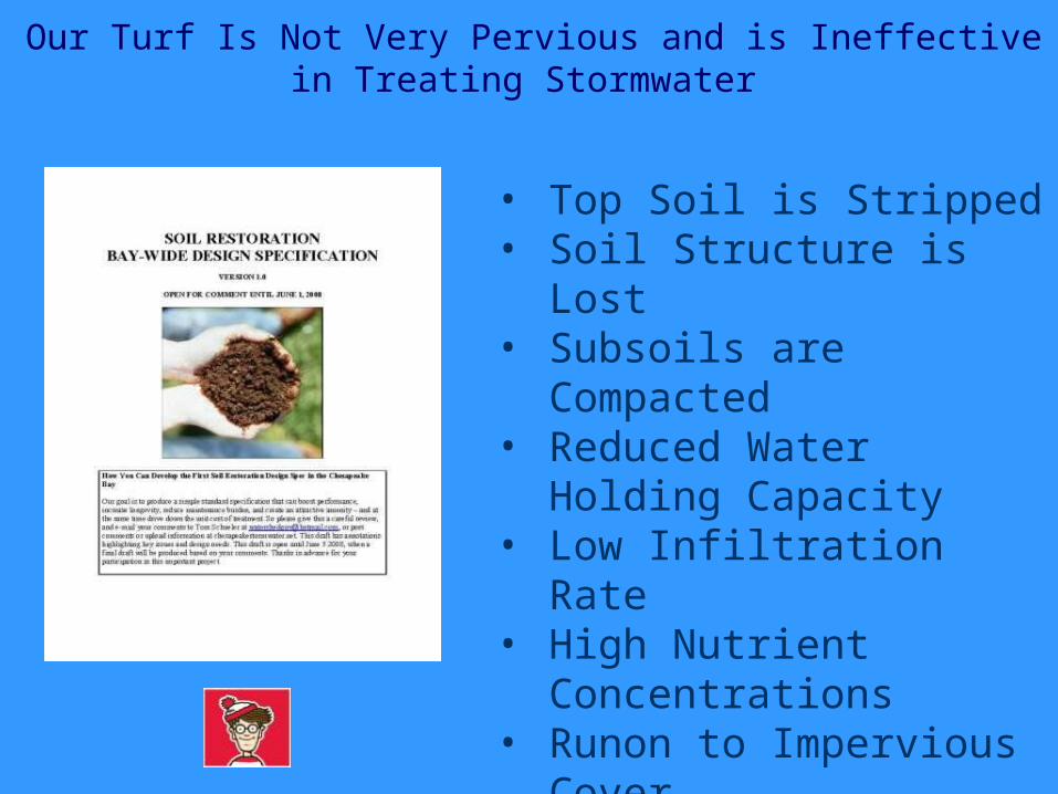
Our Turf Is Not Very Pervious and is Ineffective in Treating Stormwater
• Top Soil is Stripped• Soil Structure is Lost• Subsoils are Compacted• Reduced Water Holding
Capacity • Low Infiltration Rate• High Nutrient
Concentrations• Runon to Impervious
Cover
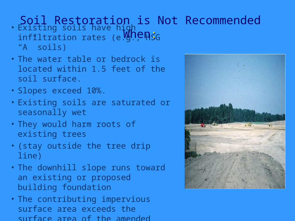
• Existing soils have high infiltration rates (e.g., HSG “A” soils)
• The water table or bedrock is located within 1.5 feet of the soil surface.
• Slopes exceed 10%.• Existing soils are saturated or
seasonally wet• They would harm roots of existing
trees • (stay outside the tree drip line) • The downhill slope runs toward an
existing or proposed building foundation
• The contributing impervious surface area exceeds the surface area of the amended soils
Soil Restoration is Not Recommended When::
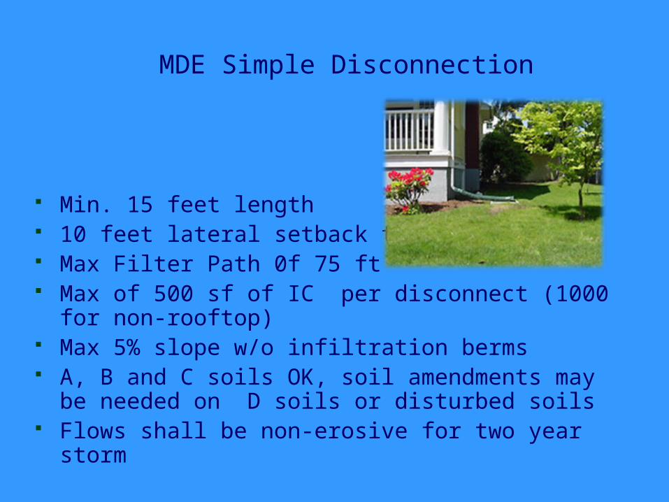
MDE Simple Disconnection
Min. 15 feet length 10 feet lateral setback to IC Max Filter Path 0f 75 ft Max of 500 sf of IC per disconnect (1000 for non-
rooftop) Max 5% slope w/o infiltration berms A, B and C soils OK, soil amendments may be
needed on D soils or disturbed soils Flows shall be non-erosive for two year storm
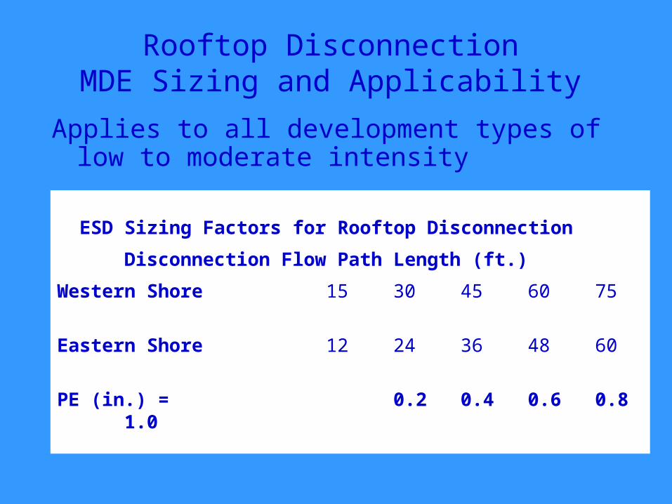
Rooftop DisconnectionMDE Sizing and Applicability
Applies to all development types of low to moderate intensity
ESD Sizing Factors for Rooftop Disconnection
Disconnection Flow Path Length (ft.)
Western Shore 15 30 45 60 75
Eastern Shore 12 24 36 48 60
PE (in.) = 0.2 0.4 0.6 0.8 1.0
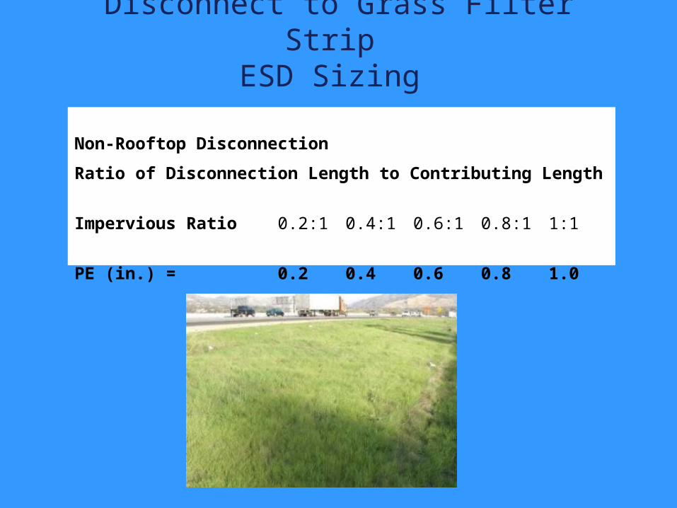
Disconnect to Grass Filter Strip ESD Sizing
Non-Rooftop Disconnection
Ratio of Disconnection Length to Contributing Length
Impervious Ratio 0.2:1 0.4:1 0.6:1 0.8:1 1:1
PE (in.) = 0.2 0.4 0.6 0.8 1.0
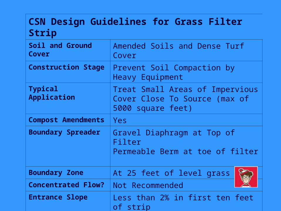
CSN Design Guidelines for Grass Filter Strip Soil and Ground Cover
Amended Soils and Dense Turf Cover
Construction Stage Prevent Soil Compaction by Heavy Equipment
Typical Application Treat Small Areas of Impervious Cover Close To Source (max of 5000 square feet)
Compost Amendments
Yes
Boundary Spreader Gravel Diaphragm at Top of Filter Permeable Berm at toe of filter
Boundary Zone At 25 feet of level grass
Concentrated Flow? Not Recommended
Entrance Slope Less than 2% in first ten feet of strip
Maximum Overall Slope
5%
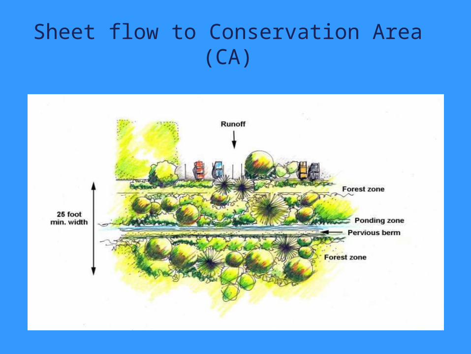
Sheet flow to Conservation Area (CA)
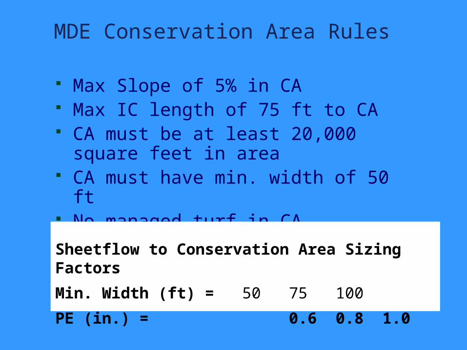
MDE Conservation Area Rules
Max Slope of 5% in CA Max IC length of 75 ft to CA CA must be at least 20,000 square
feet in area CA must have min. width of 50 ft No managed turf in CA
Sheetflow to Conservation Area Sizing Factors
Min. Width (ft) = 50 75 100
PE (in.) = 0.6 0.8 1.0
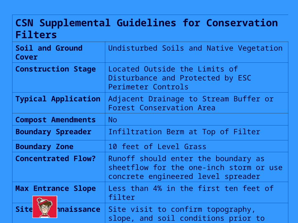
CSN Supplemental Guidelines for Conservation FiltersSoil and Ground Cover
Undisturbed Soils and Native Vegetation
Construction Stage Located Outside the Limits of Disturbance and Protected by ESC Perimeter Controls
Typical Application Adjacent Drainage to Stream Buffer or Forest Conservation Area
Compost Amendments
No
Boundary Spreader Infiltration Berm at Top of Filter
Boundary Zone 10 feet of Level Grass
Concentrated Flow? Runoff should enter the boundary as sheetflow for the one-inch storm or use concrete engineered level spreader
Max Entrance Slope Less than 4% in the first ten feet of filter
Site Reconnaissance Site visit to confirm topography, slope, and soil conditions prior to design
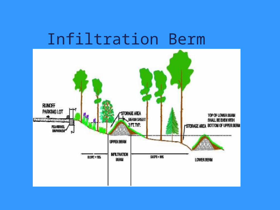
Infiltration Berm
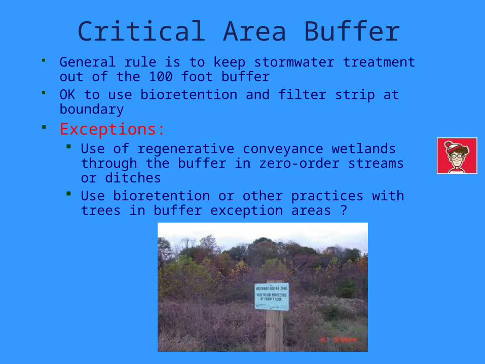
Critical Area Buffer General rule is to keep stormwater treatment out of
the 100 foot buffer OK to use bioretention and filter strip at boundary Exceptions:
Use of regenerative conveyance wetlands through the buffer in zero-order streams or ditches
Use bioretention or other practices with trees in buffer exception areas ?
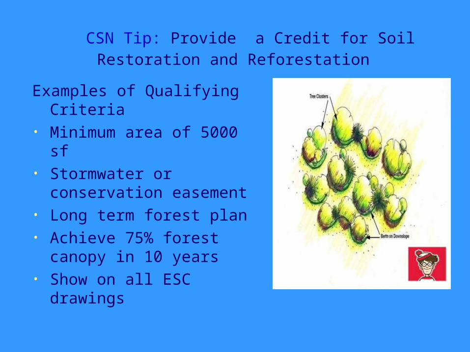
CSN Tip: Provide a Credit for Soil Restoration and Reforestation
Examples of Qualifying Criteria
• Minimum area of 5000 sf • Stormwater or
conservation easement• Long term forest plan• Achieve 75% forest
canopy in 10 years• Show on all ESC drawings

Credits Are Easy to Show on Plan
But Will They Actually Show Up at the Site?
Four Stage Review:
1.Evaluate Feasibility During Concept Design
2.Confirm Area in Final Design
3.Protect During Construction inspection
4.Verify as Part of Final Stormwater Acceptance
Design of ESD Micro-Practices
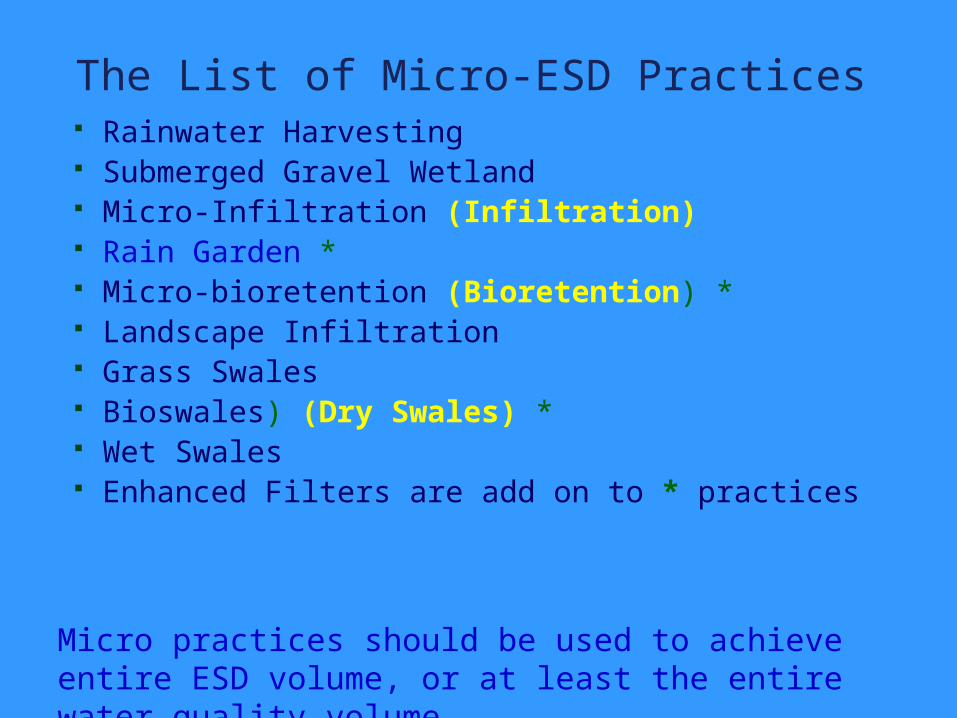
The List of Micro-ESD Practices Rainwater Harvesting Submerged Gravel Wetland Micro-Infiltration (Infiltration) Rain Garden * Micro-bioretention (Bioretention) * Landscape Infiltration Grass Swales Bioswales) (Dry Swales) * Wet Swales Enhanced Filters are add on to * practices
Micro practices should be used to achieve entire ESD volume, or at least the entire water quality volume
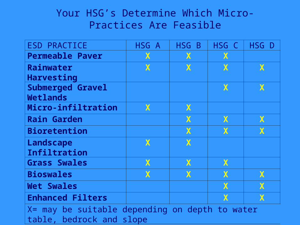
ESD PRACTICE HSG A HSG B HSG C HSG DPermeable Paver X X XRainwater Harvesting
X X X X
Submerged Gravel Wetlands
X X
Micro-infiltration X XRain Garden X X XBioretention X X XLandscape Infiltration
X X
Grass Swales X X XBioswales X X X XWet Swales X XEnhanced Filters X XX= may be suitable depending on depth to water table, bedrock and slope
Your HSG’s Determine Which Micro-Practices Are Feasible
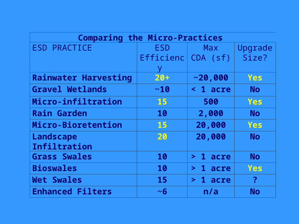
Comparing the Micro-Practices ESD PRACTICE ESD
Efficiency Max
CDA (sf)Upgrade
Size?Rainwater Harvesting 20+ ~20,000 YesGravel Wetlands ~10 < 1 acre NoMicro-infiltration 15 500 YesRain Garden 10 2,000 NoMicro-Bioretention 15 20,000 YesLandscape Infiltration
20 20,000 No
Grass Swales 10 > 1 acre NoBioswales 10 > 1 acre YesWet Swales 15 > 1 acre ?Enhanced Filters ~6 n/a No
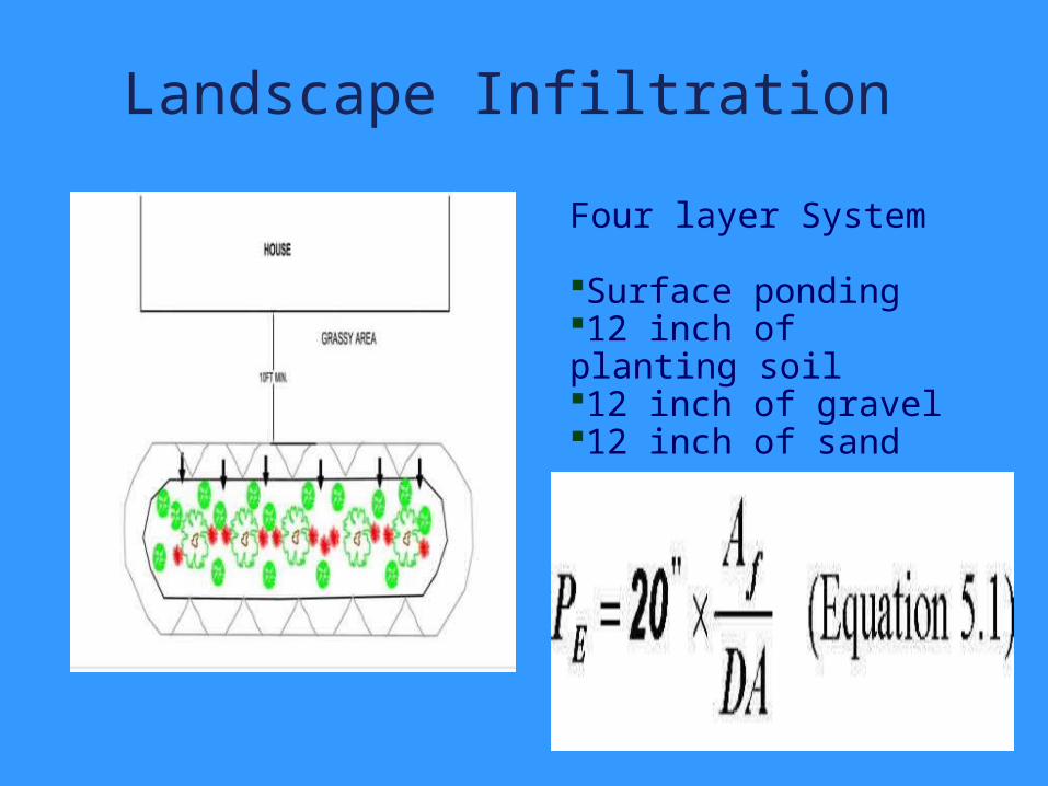
Landscape Infiltration
.
Four layer System
Surface ponding12 inch of planting soil 12 inch of gravel 12 inch of sand
Landscape Infiltration Restricted to A & B soils Max CDA of 10,000 sf (w/o soil testing
and pretreatment)• This has the best ESD reduction of any
micro-ESD practice per square foot of practice surface area
.
Essentially an infiltrating bioretention facility w/o underdrain
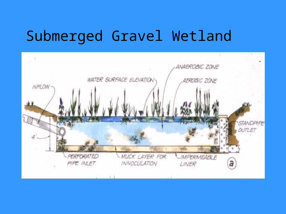
Submerged Gravel Wetland
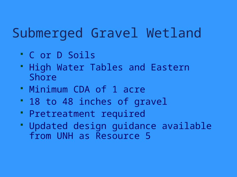
Submerged Gravel Wetland C or D Soils High Water Tables and Eastern Shore Minimum CDA of 1 acre 18 to 48 inches of gravel Pretreatment required Updated design guidance available from
UNH as Resource 5
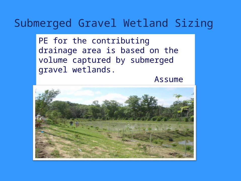
Submerged Gravel Wetland Sizing
PE for the contributing drainage area is based on the volume captured by submerged gravel wetlands. Assume about 10 inches
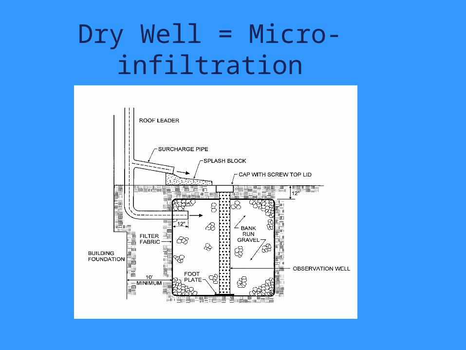
Dry Well = Micro-infiltration
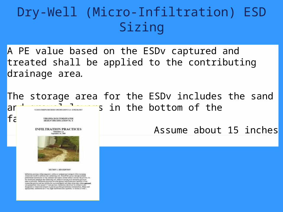
Dry-Well (Micro-Infiltration) ESD Sizing
A PE value based on the ESDv captured and treated shall be applied to the contributing drainage area.
The storage area for the ESDv includes the sand and gravel layers in the bottom of the facility.
Assume about 15 inches
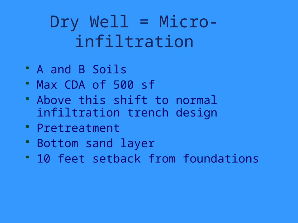
Dry Well = Micro-infiltration A and B Soils Max CDA of 500 sf Above this shift to normal infiltration
trench design Pretreatment Bottom sand layer 10 feet setback from foundations
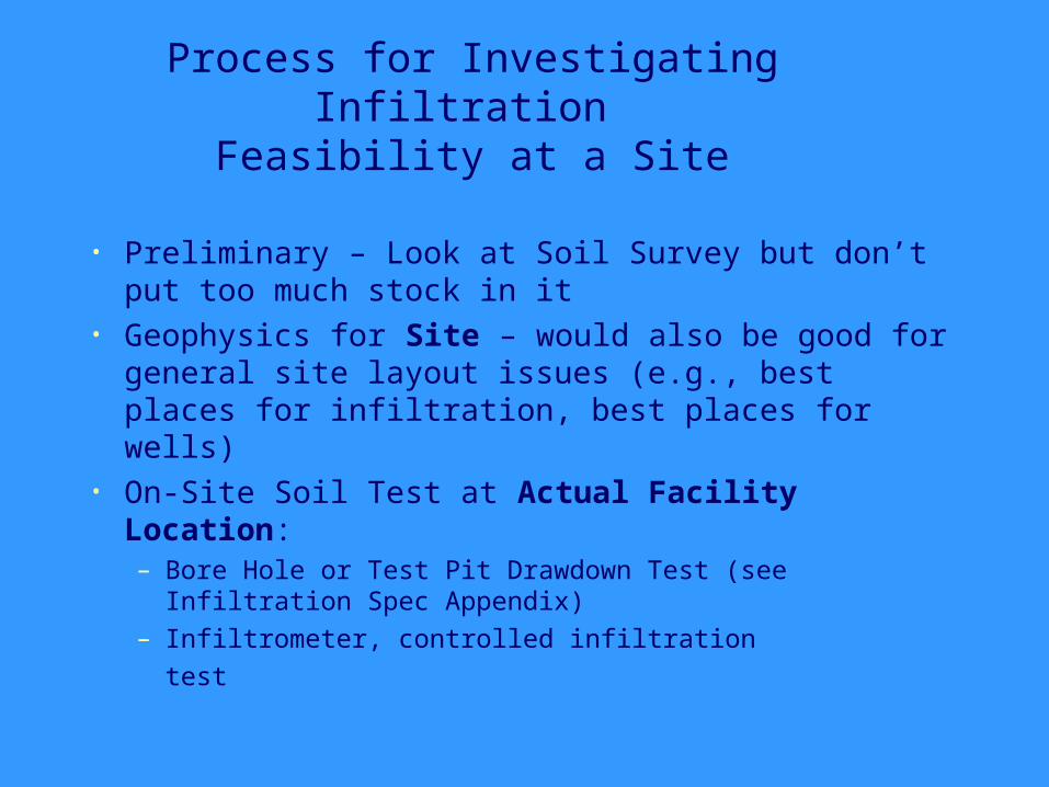
Process for Investigating Infiltration Feasibility at a Site
• Preliminary – Look at Soil Survey but don’t put too much stock in it
• Geophysics for Site – would also be good for general site layout issues (e.g., best places for infiltration, best places for wells)
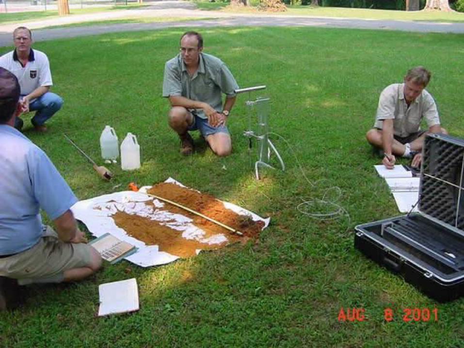
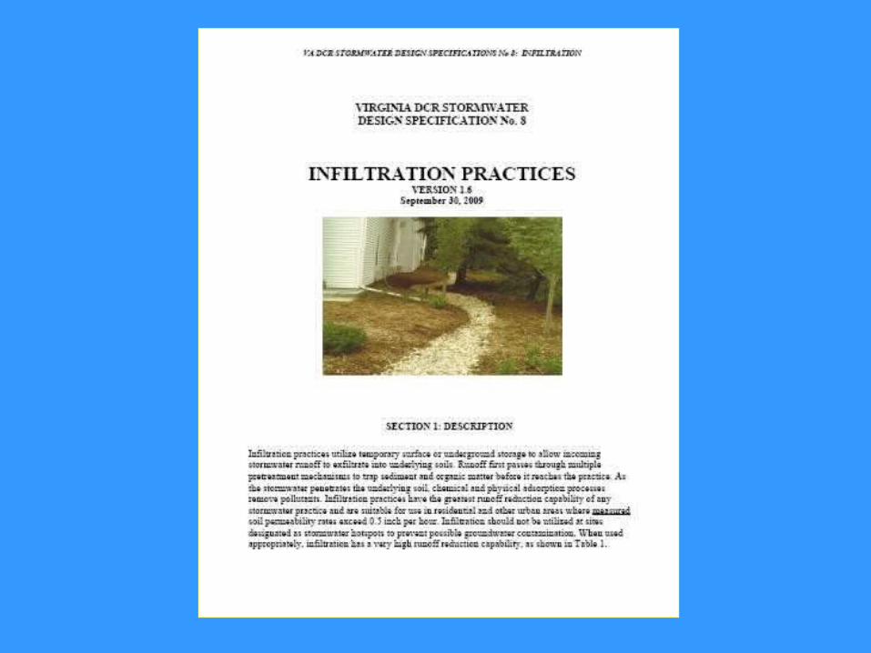
• On-Site Soil Test at Actual Facility Location:– Bore Hole or Test Pit Drawdown Test (see Infiltration
Spec Appendix)– Infiltrometer, controlled infiltration
test
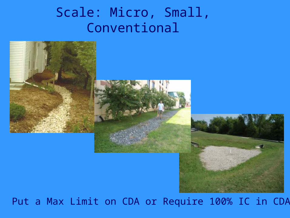
Put a Max Limit on CDA or Require 100% IC in CDA?
Scale: Micro, Small, Conventional
Rainwater HarvestingESD Sizing and Applicability
Not a lot of design constraints Spreadsheet available to determine the
ESD volume actually captured based on indoor and outdoor demand
Rain barrels and cisterns shall be designed to capture at least 0.2 inches of rainfall from the contributing rooftop area.
A PE value based on the ESDv captured and treated shall be applied to the contributing rooftop area.
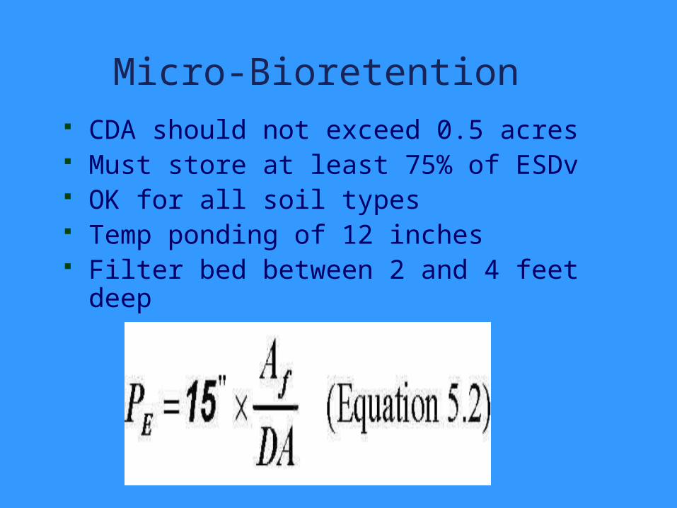
Micro-Bioretention CDA should not exceed 0.5 acres Must store at least 75% of ESDv OK for all soil types Temp ponding of 12 inches Filter bed between 2 and 4 feet deep
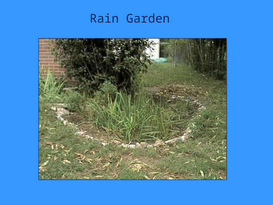
Rain Garden
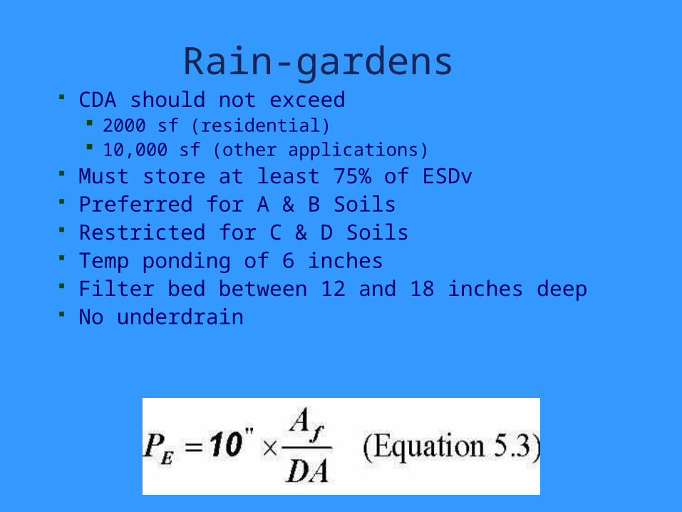
Rain-gardens CDA should not exceed
2000 sf (residential) 10,000 sf (other applications)
Must store at least 75% of ESDv Preferred for A & B Soils Restricted for C & D Soils Temp ponding of 6 inches Filter bed between 12 and 18 inches deep No underdrain
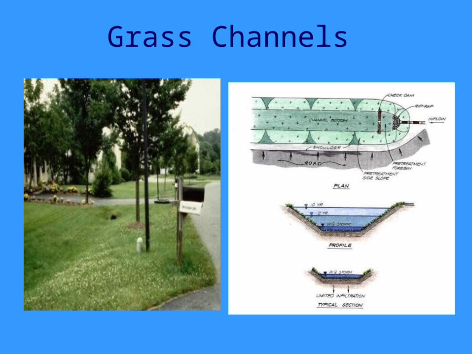
Grass Channels
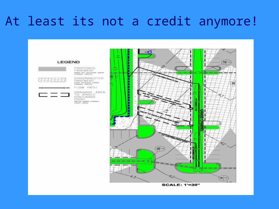
At least its not a credit anymore!
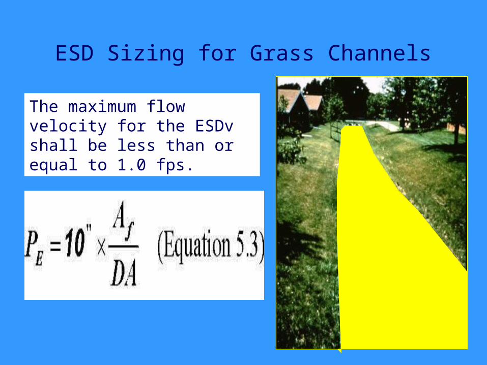
ESD Sizing for Grass Channels
The maximum flow velocity for the ESDv shall be less than or equal to 1.0 fps.
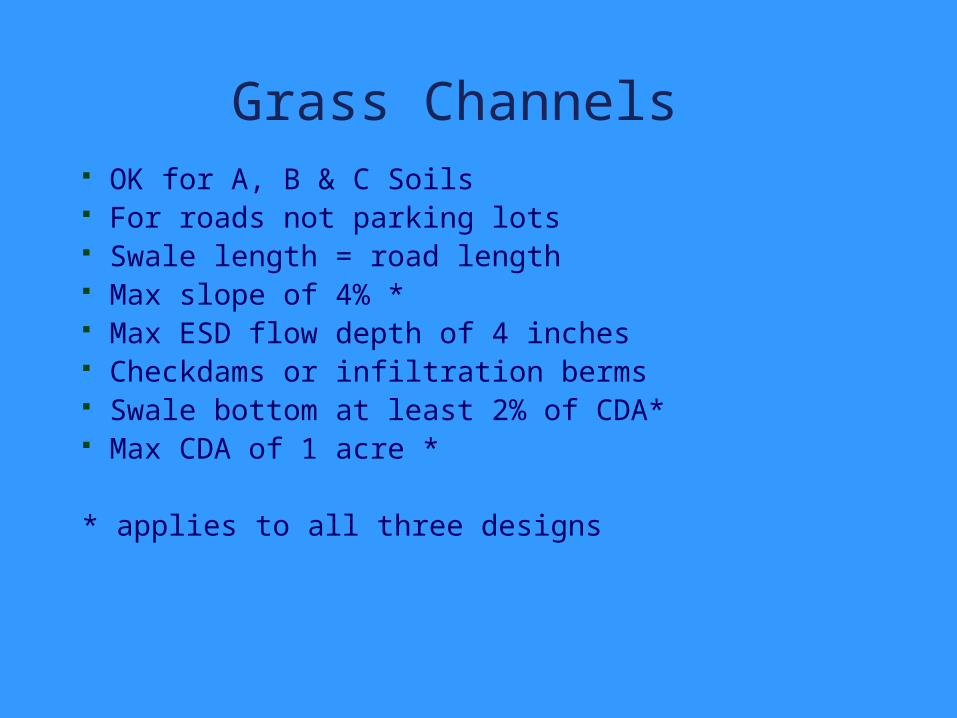
Grass Channels OK for A, B & C Soils For roads not parking lots Swale length = road length Max slope of 4% * Max ESD flow depth of 4 inches Checkdams or infiltration berms Swale bottom at least 2% of CDA* Max CDA of 1 acre *
* applies to all three designs
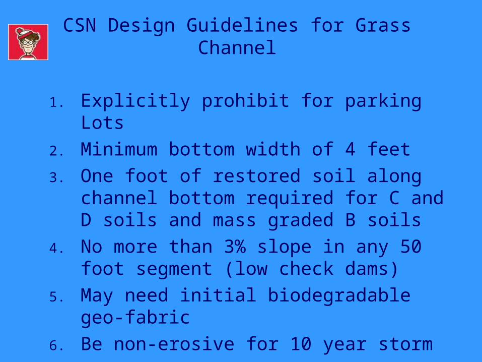
CSN Design Guidelines for Grass Channel
1. Explicitly prohibit for parking Lots2. Minimum bottom width of 4 feet3. One foot of restored soil along channel
bottom required for C and D soils and mass graded B soils
4. No more than 3% slope in any 50 foot segment (low check dams)
5. May need initial biodegradable geo-fabric
6. Be non-erosive for 10 year storm
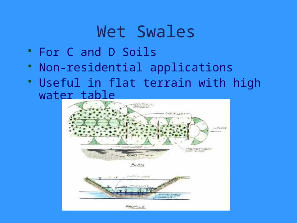
Wet Swales For C and D Soils Non-residential applications Useful in flat terrain with high water
table
Wet SwaleSizing
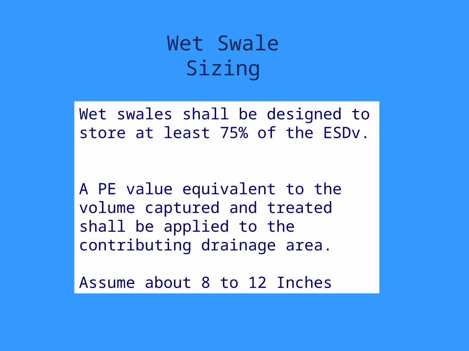
Wet swales shall be designed to store at least 75% of the ESDv.
A PE value equivalent to the volume captured and treated shall be applied to the contributing drainage area.
Assume about 8 to 12 Inches
CSN Wet Swale Design Criteria
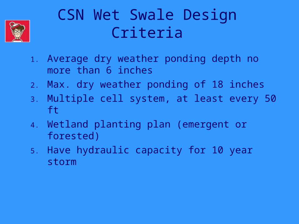
1. Average dry weather ponding depth no more than 6 inches
2. Max. dry weather ponding of 18 inches3. Multiple cell system, at least every 50 ft4. Wetland planting plan (emergent or
forested) 5. Have hydraulic capacity for 10 year
storm
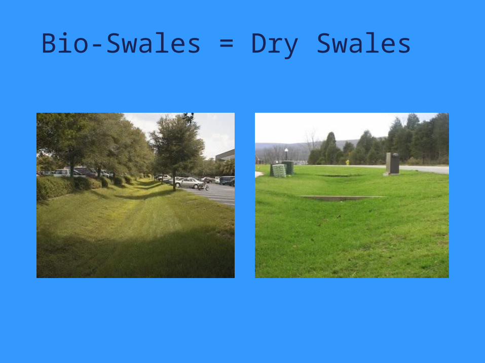
Bio-Swales = Dry Swales
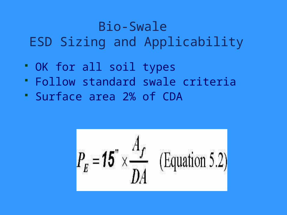
Bio-Swale ESD Sizing and Applicability
OK for all soil types Follow standard swale criteria Surface area 2% of CDA