Embed Size (px)
Citation preview

Basic Selection & Proper Application
of Overhead Air Distribution Devices
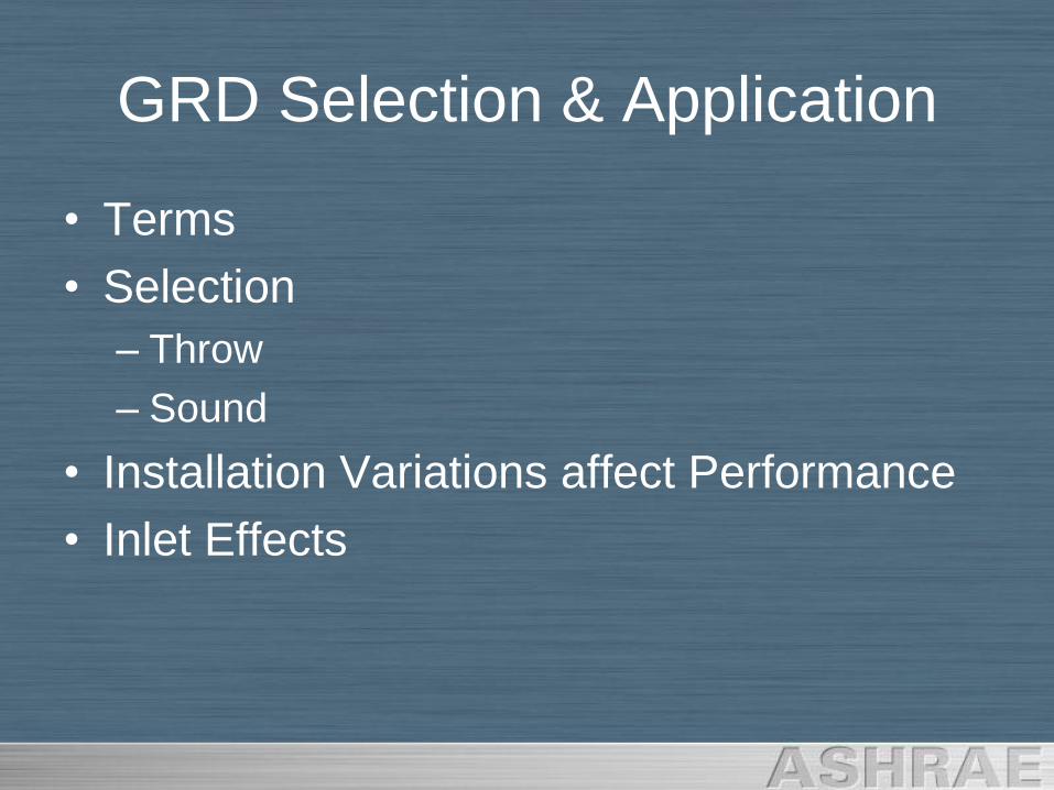
GRD Selection & Application
• Terms
• Selection
– Throw
– Sound
• Installation Variations affect Performance
• Inlet Effects
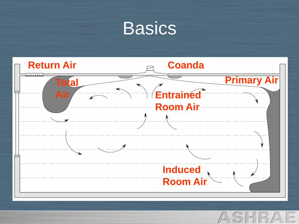
Basics
Coanda
Total
Air
Primary Air
Induced
Room Air
Entrained
Room Air
Return Air
Basics
• ASHRAE Standard 70-2006
– Standard Defines Testing Procedures,
Spaces, and Equipment
– Isothermal Testing
– Non-Turbulent, Smooth Inlet Conditions
– Obtain Catalog Data
Selection – Throw
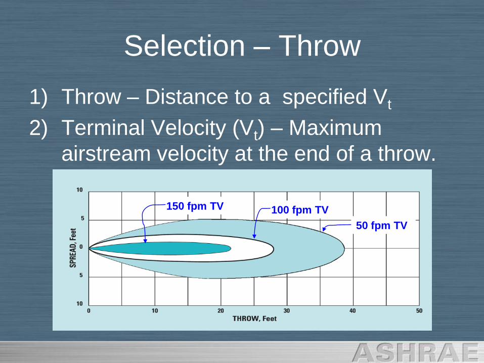
1) Throw – Distance to a specified Vt
2) Terminal Velocity (Vt) – Maximum
airstream velocity at the end of a throw.
50 fpm TV
100 fpm TV150 fpm TV
Selection – Throw
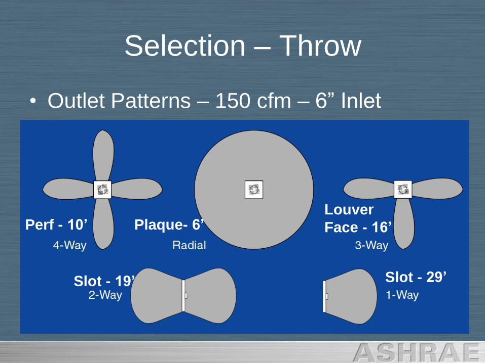
• Outlet Patterns – 150 cfm – 6” Inlet
Plaque- 6’
Slot - 19’ Slot - 29’
Perf - 10’Louver
Face - 16’
Selection – Throw
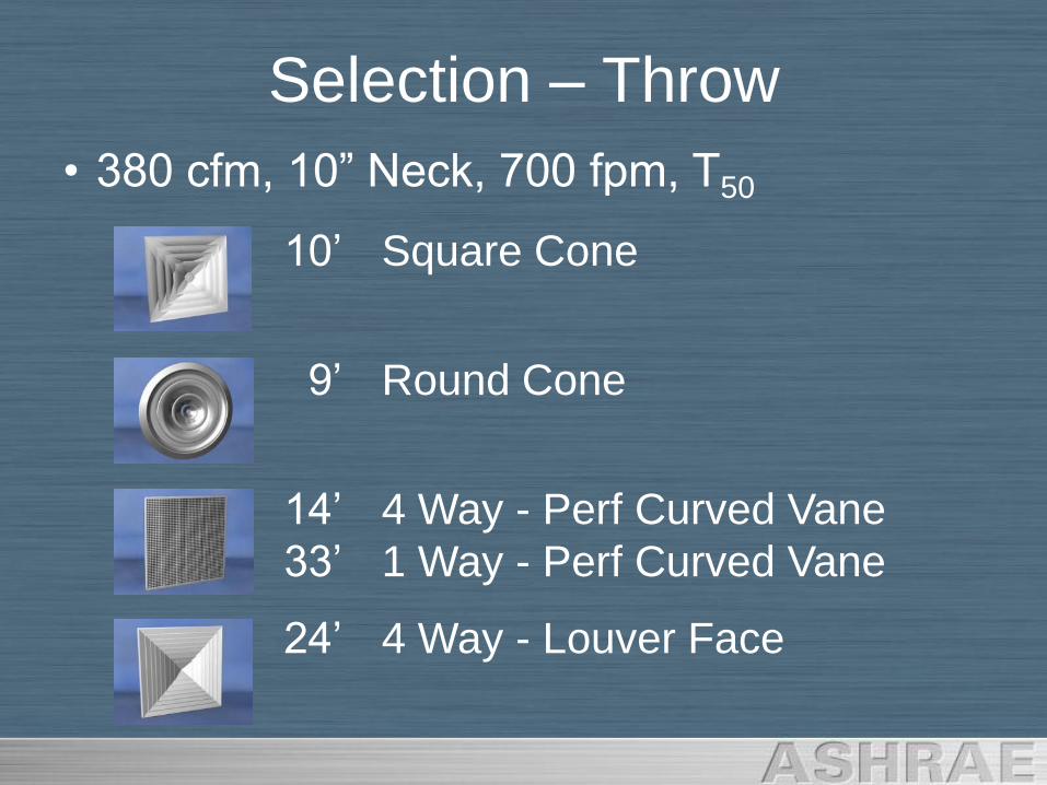
• 380 cfm, 10” Neck, 700 fpm, T50
10‟ Square Cone
9‟ Round Cone
14‟ 4 Way - Perf Curved Vane
33‟ 1 Way - Perf Curved Vane
24‟ 4 Way - Louver Face
Selection – Throw
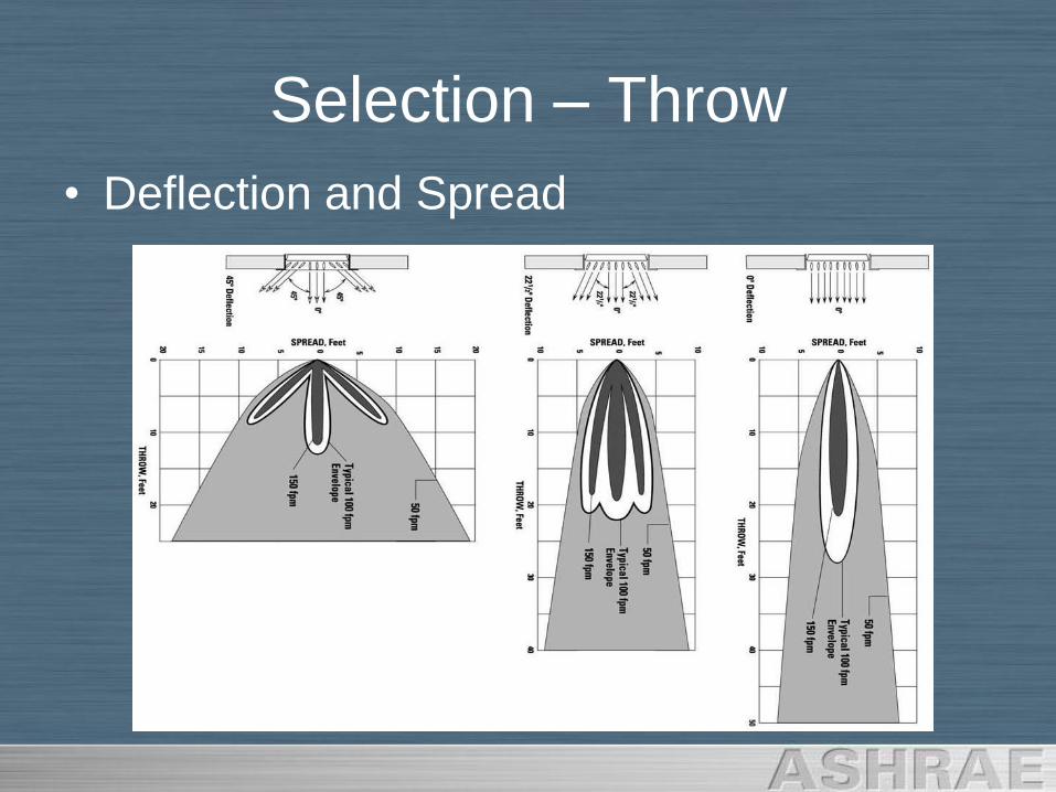
• Deflection and Spread
Selection – Throw
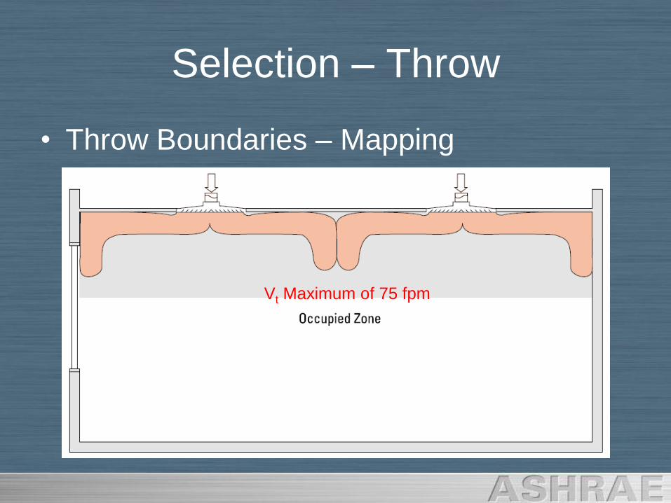
• Throw Boundaries – Mapping
Vt Maximum of 75 fpm
Selection – Throw
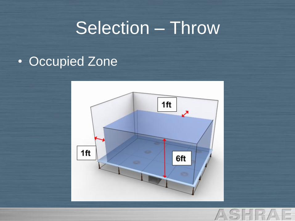
• Occupied Zone
Selection – Throw
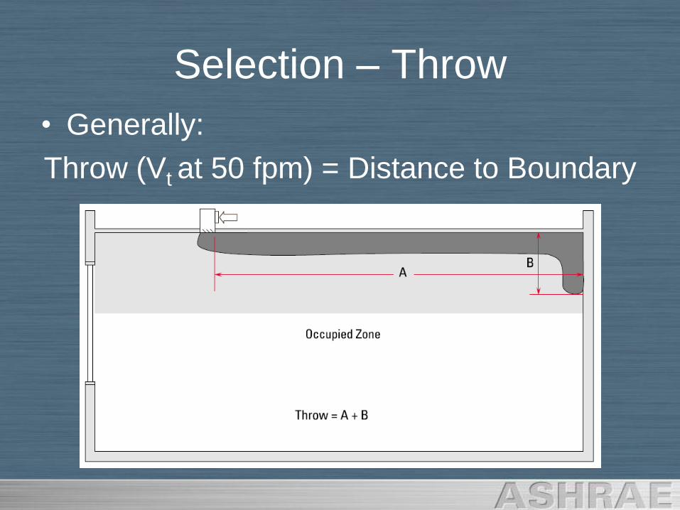
• Generally:
Throw (Vt at 50 fpm) = Distance to Boundary
Selection – Throw
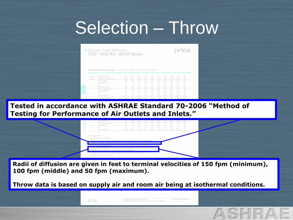
Tested in accordance with ASHRAE Standard 70-2006 “Method of Testing for Performance of Air Outlets and Inlets.”
Radii of diffusion are given in feet to terminal velocities of 150 fpm (minimum), 100 fpm (middle) and 50 fpm (maximum).
Throw data is based on supply air and room air being at isothermal conditions.
Selection – Throw
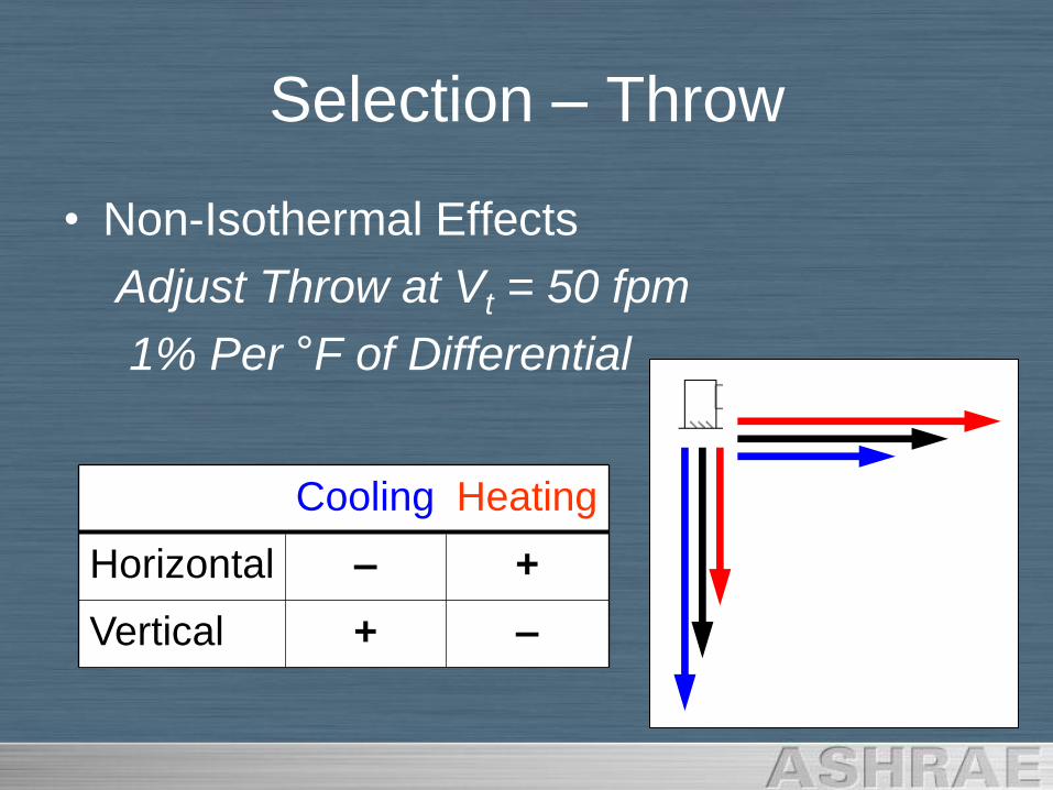
• Non-Isothermal Effects
Adjust Throw at Vt = 50 fpm
1% Per °F of Differential
Cooling Heating
Horizontal – +
Vertical + –
Selection – Throw
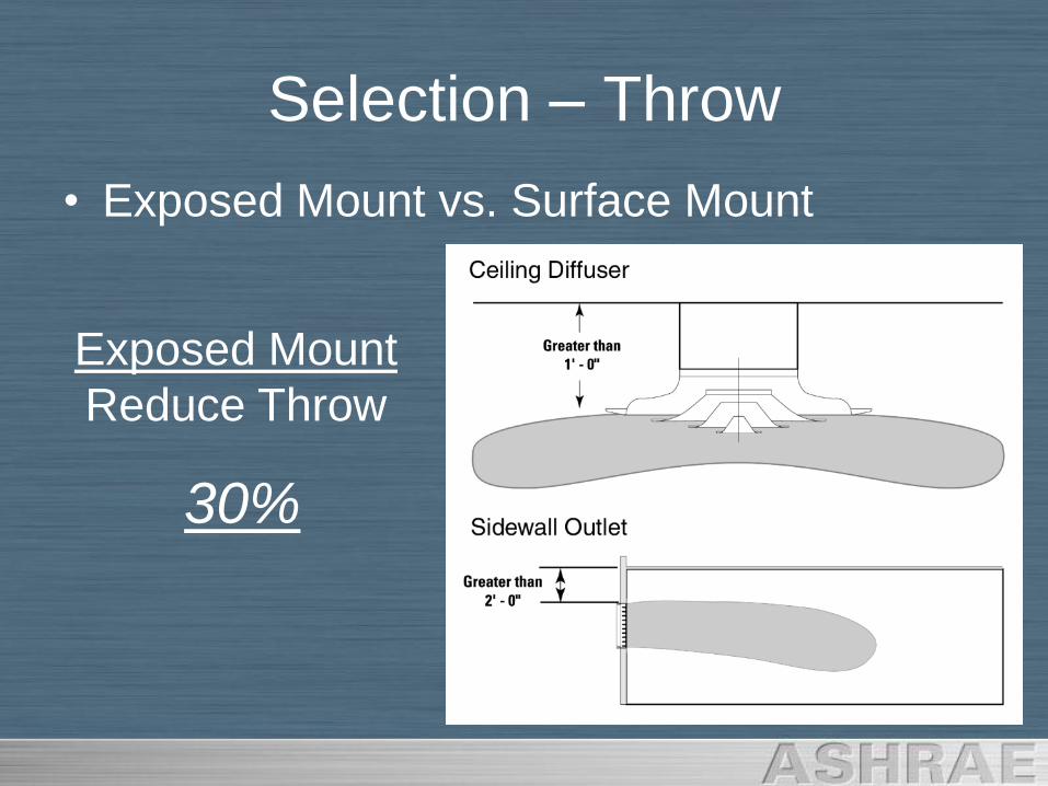
• Exposed Mount vs. Surface Mount
Exposed Mount
Reduce Throw
30%
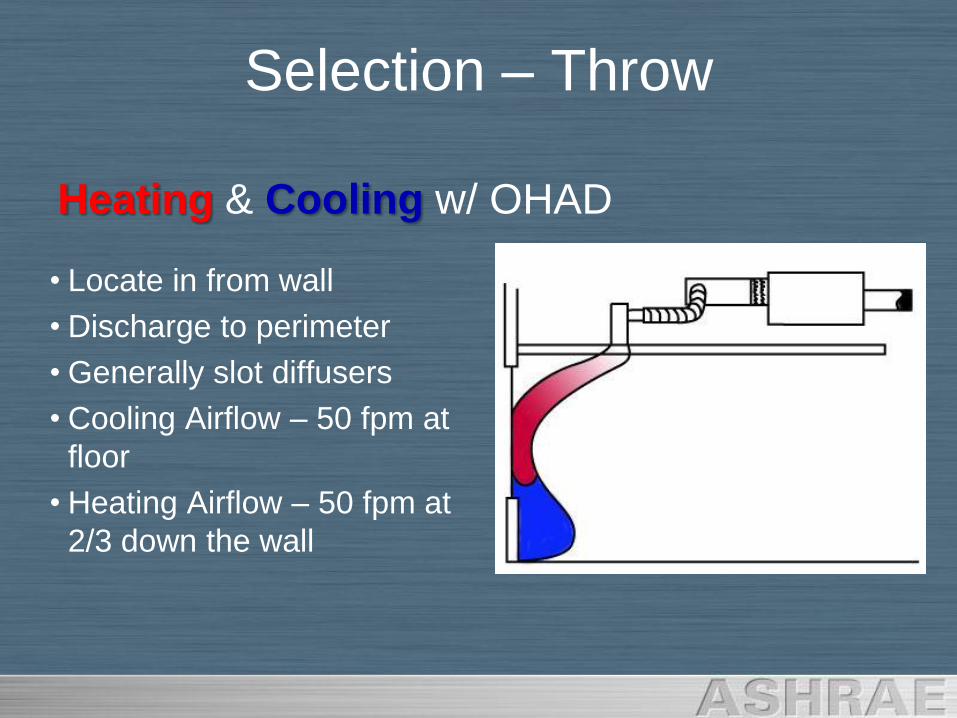
• Locate in from wall
• Discharge to perimeter
• Generally slot diffusers
• Cooling Airflow – 50 fpm at
floor
• Heating Airflow – 50 fpm at
2/3 down the wall
Heating & Cooling w/ OHAD
Selection – Throw
Selection – Throw
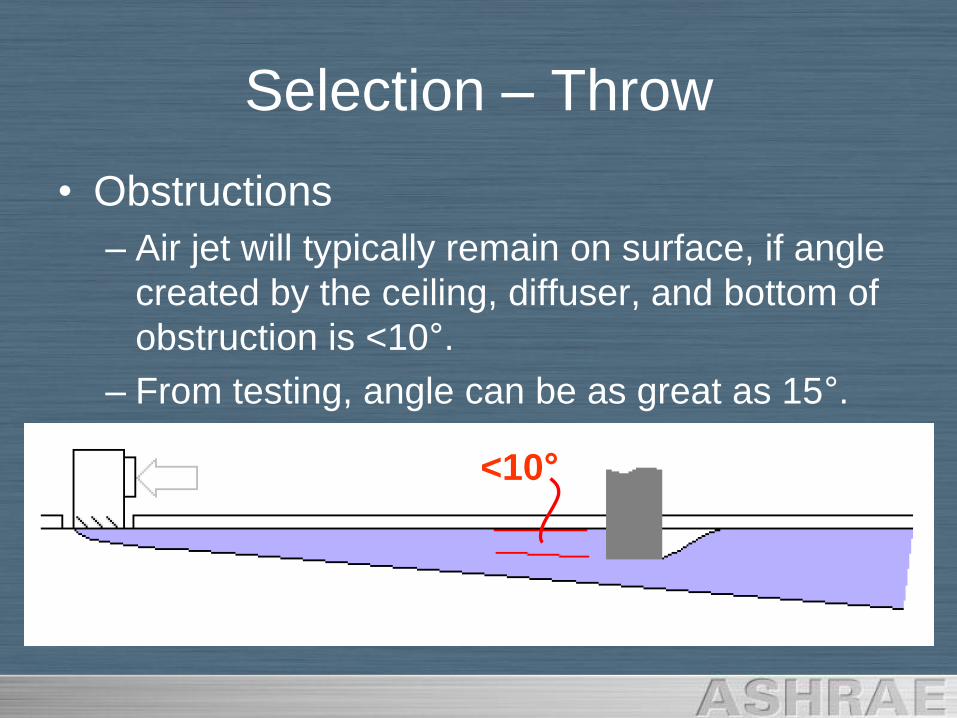
• Obstructions
– Air jet will typically remain on surface, if angle
created by the ceiling, diffuser, and bottom of
obstruction is <10°.
– From testing, angle can be as great as 15°.
<10°
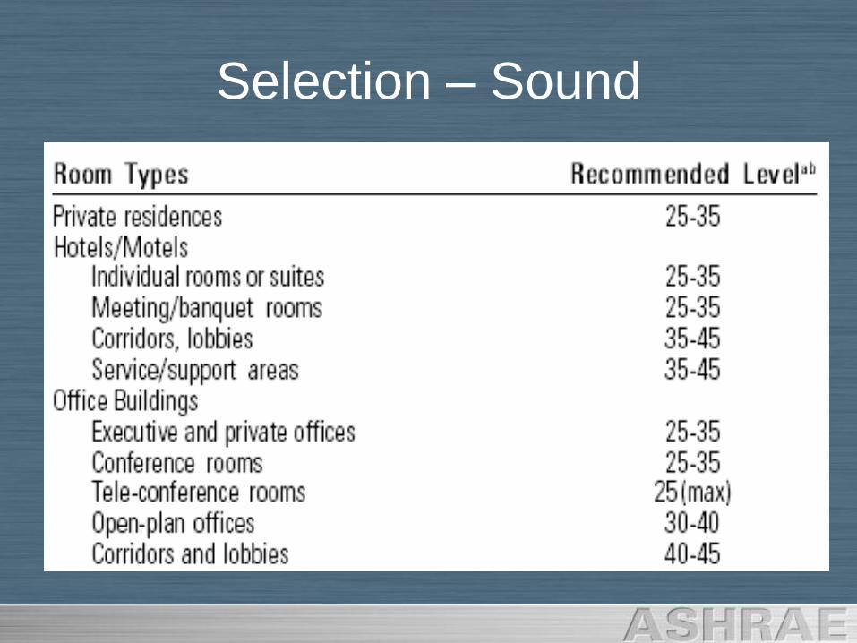
Selection – Sound
• Catalog Data
– NC Rating
• Average Room Size
• Distance from Source
– Assumes 10 dB Room Absorption
– Single Diffuser or Standard Length
Selection – Sound
Selection – Sound
Selection – Sound
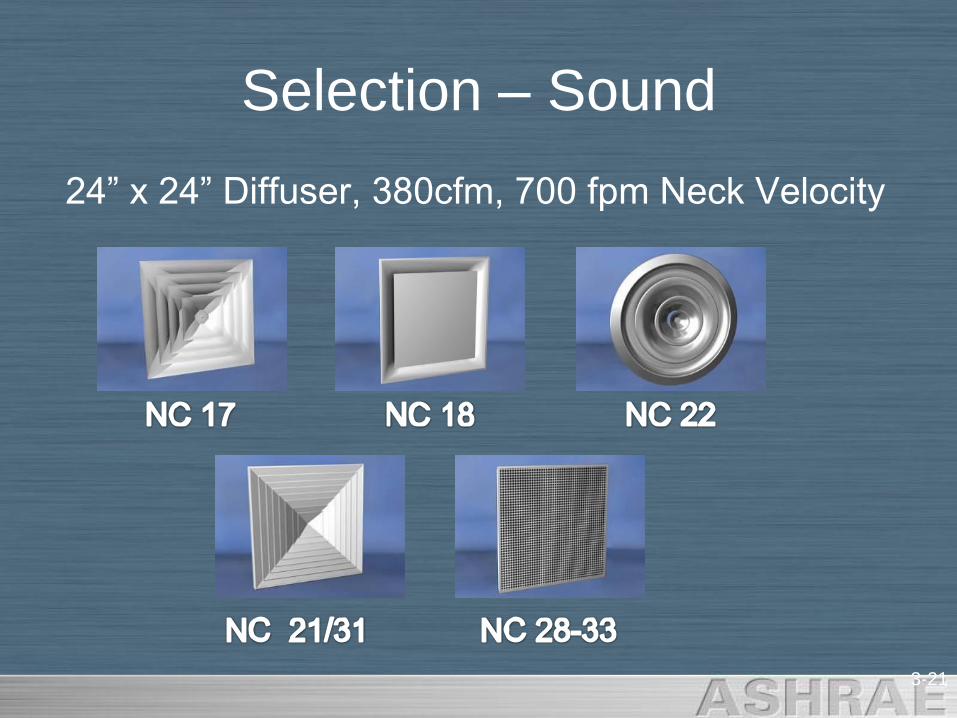
24” x 24” Diffuser, 380cfm, 700 fpm Neck Velocity
3-21
Selection – Sound
NC 453-22
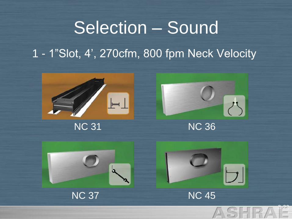
Selection – Sound
NC 37
NC 36NC 31
1 - 1”Slot, 4‟, 270cfm, 800 fpm Neck Velocity
3-23
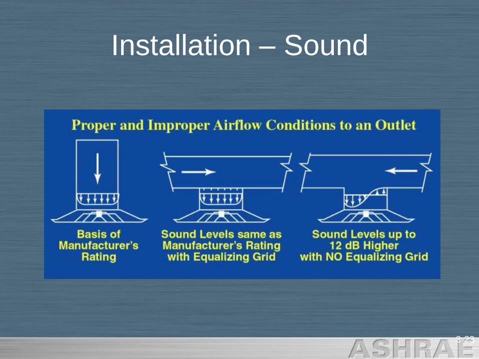
Installation – Sound
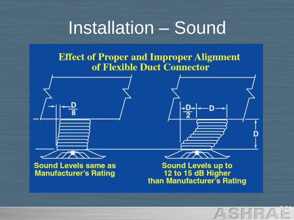
3-24
Installation – Sound
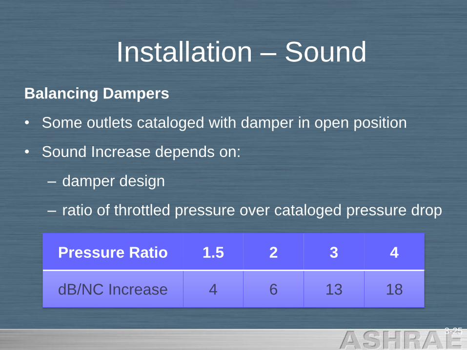
Balancing Dampers
• Some outlets cataloged with damper in open position
• Sound Increase depends on:
– damper design
– ratio of throttled pressure over cataloged pressure drop
3-25
Installation – Sound
Pressure Ratio 1.5 2 3 4
dB/NC Increase 4 6 13 18
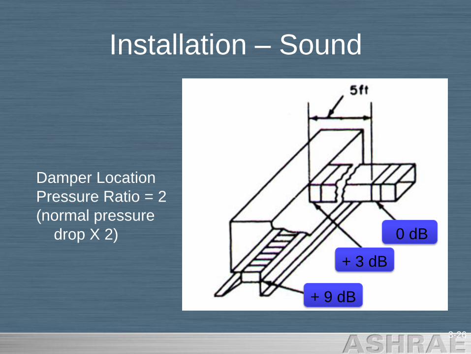
Damper Location
Pressure Ratio = 2
(normal pressure
drop X 2)
3-26
Installation – Sound
0 dB
+ 3 dB
+ 9 dB

Inlet Effects
ASHRAE Standard 70 – Throw Room
• Measurements taken in a „Standard Test Room‟
– Height => 9‟
– Minimum Length = 24‟
– Minimum Width = 18‟
– All lights and windows shall be flush to the surface they
are attached.
– Air exhausted away from supply path.
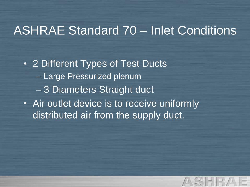
• 2 Different Types of Test Ducts
– Large Pressurized plenum
– 3 Diameters Straight duct
• Air outlet device is to receive uniformly
distributed air from the supply duct.
ASHRAE Standard 70 – Inlet Conditions
Effect of Inlet Conditions on Throw
• Test Standard Installation
– Repeatable, uniform throw distances
– Repeatable, drop
– Repeatable, discharge pattern
• Hard 90 Degree Elbow
• Flex Duct 90 Degree Elbow
• Radial Opposed Blade Damper
• Butterfly Damper
• Bowtie Damper
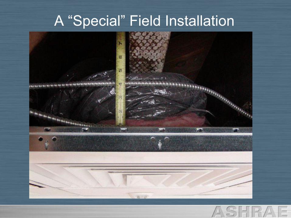
A “Special” Field Installation
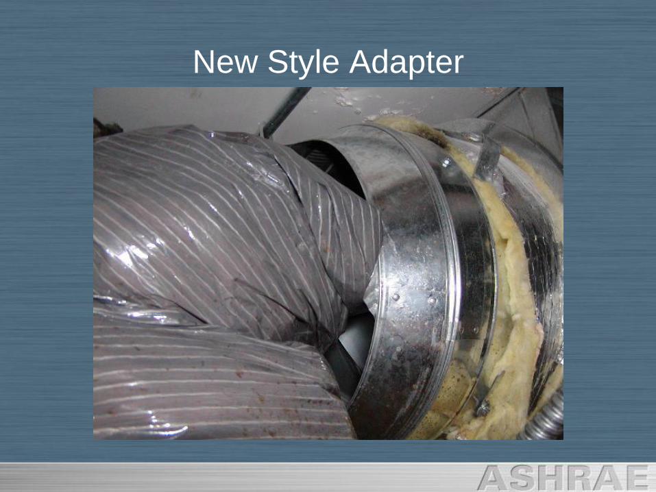
New Style Adapter

More Poor Workmanship Examples
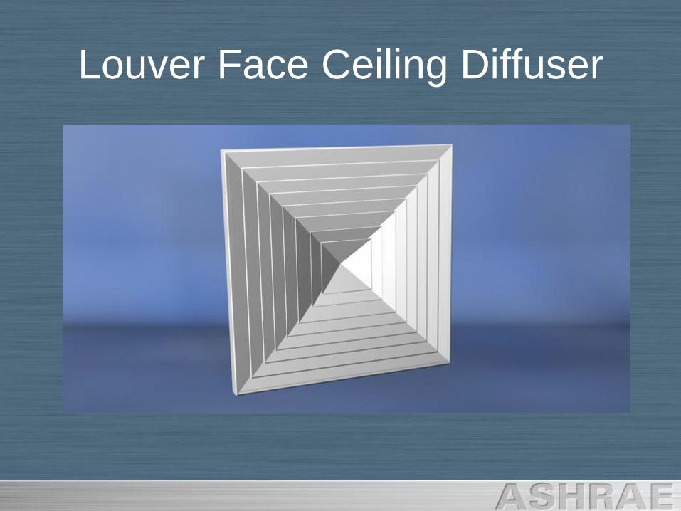
Louver Face Ceiling Diffuser
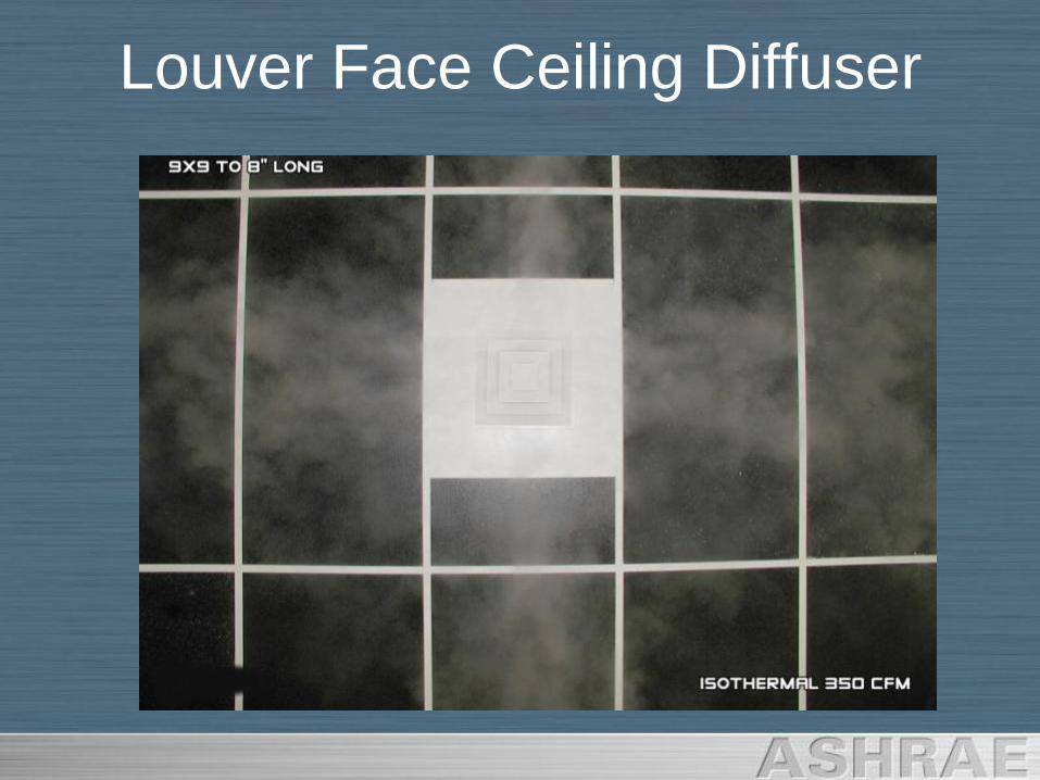
Louver Face Ceiling Diffuser
Louver Face Ceiling Diffuser
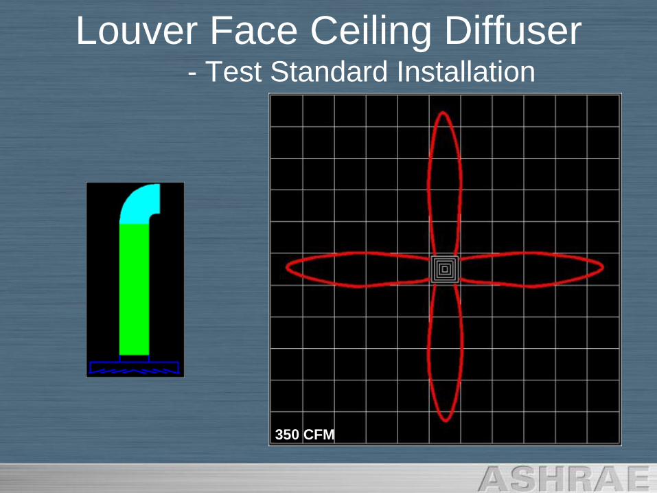
Louver Face Ceiling Diffuser- Test Standard Installation
350 CFM
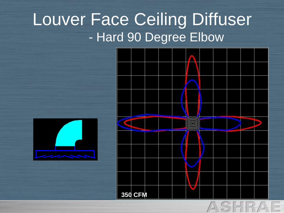
Louver Face Ceiling Diffuser- Hard 90 Degree Elbow
350 CFM
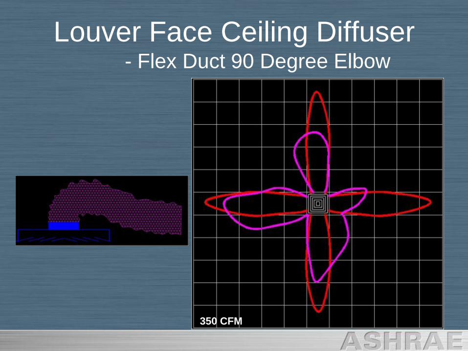
Louver Face Ceiling Diffuser- Flex Duct 90 Degree Elbow
350 CFM
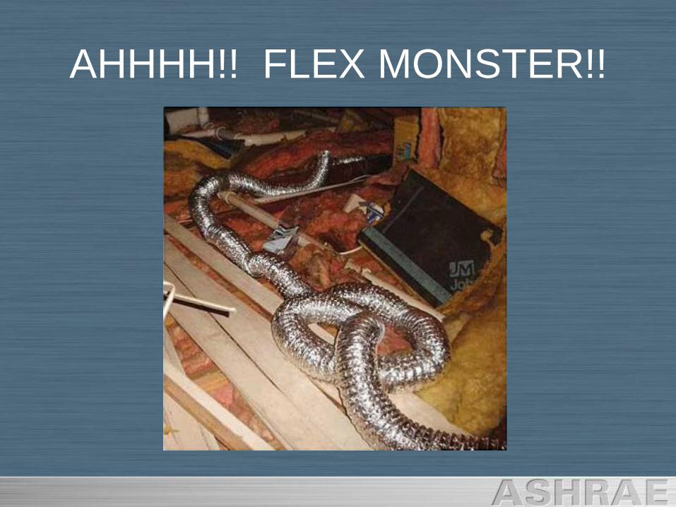
AHHHH!! FLEX MONSTER!!
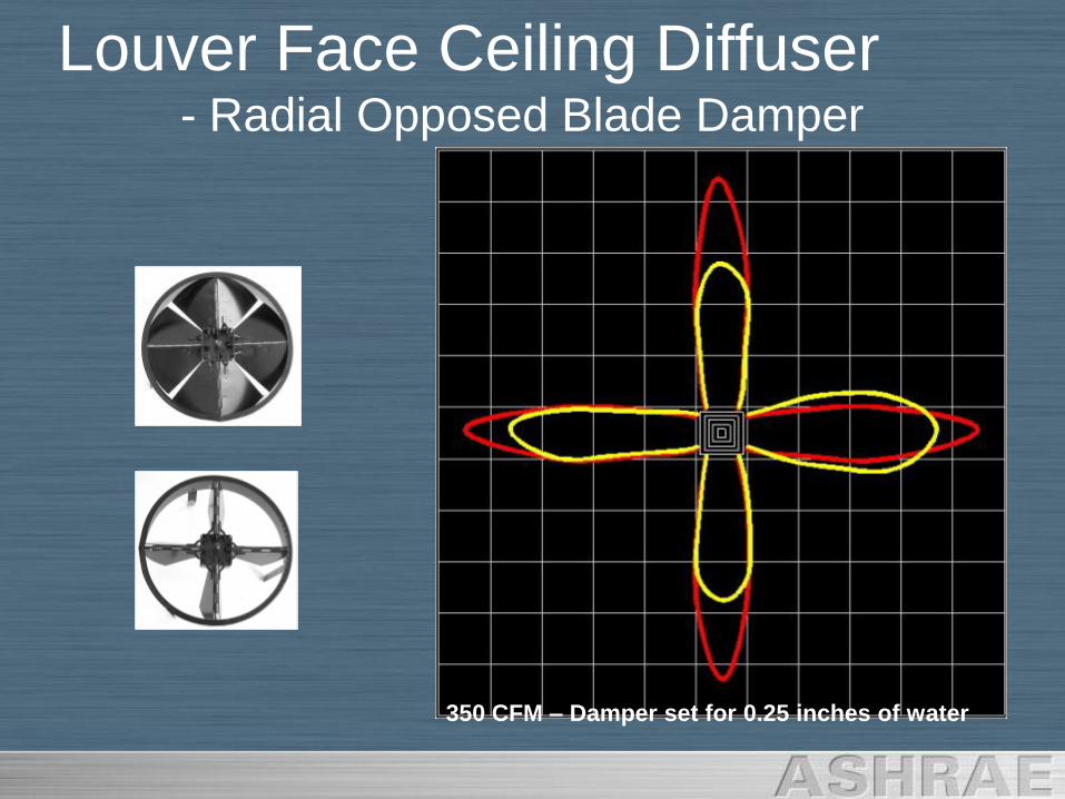
Louver Face Ceiling Diffuser- Radial Opposed Blade Damper
350 CFM – Damper set for 0.25 inches of water
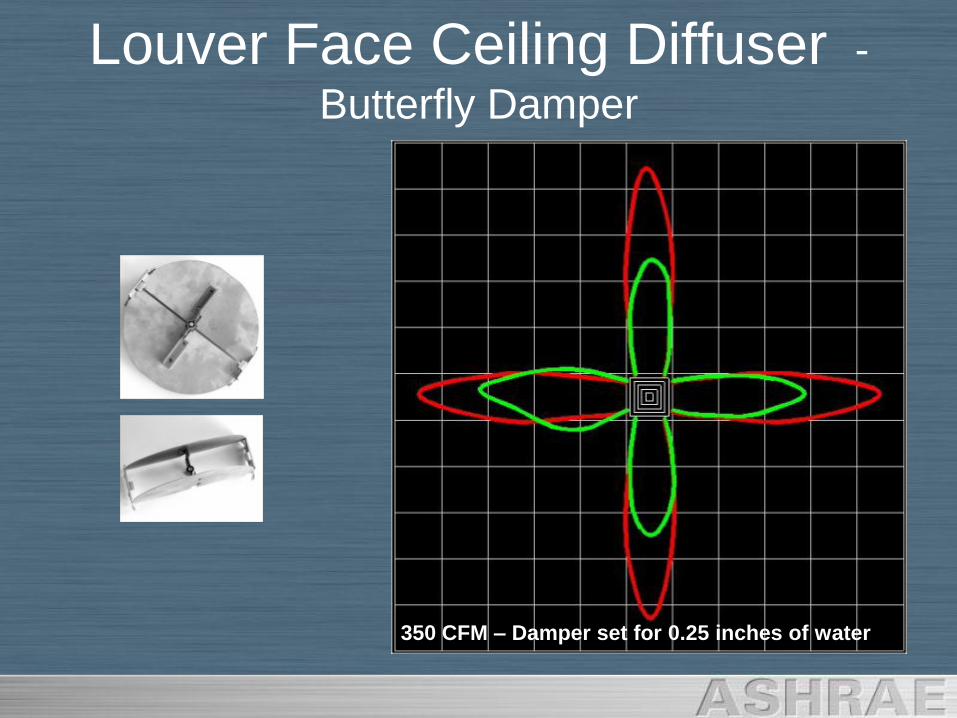
Louver Face Ceiling Diffuser -
Butterfly Damper
350 CFM – Damper set for 0.25 inches of water
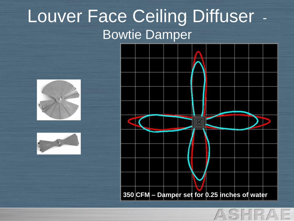
Louver Face Ceiling Diffuser -
Bowtie Damper
350 CFM – Damper set for 0.25 inches of water
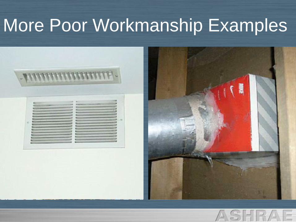
More Poor Workmanship Examples
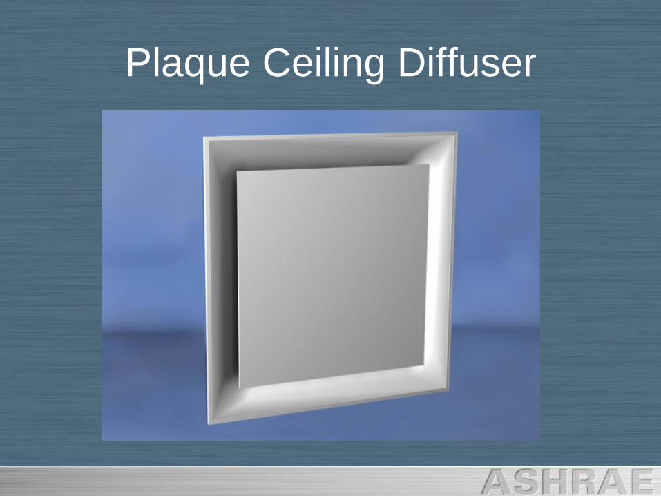
Plaque Ceiling Diffuser
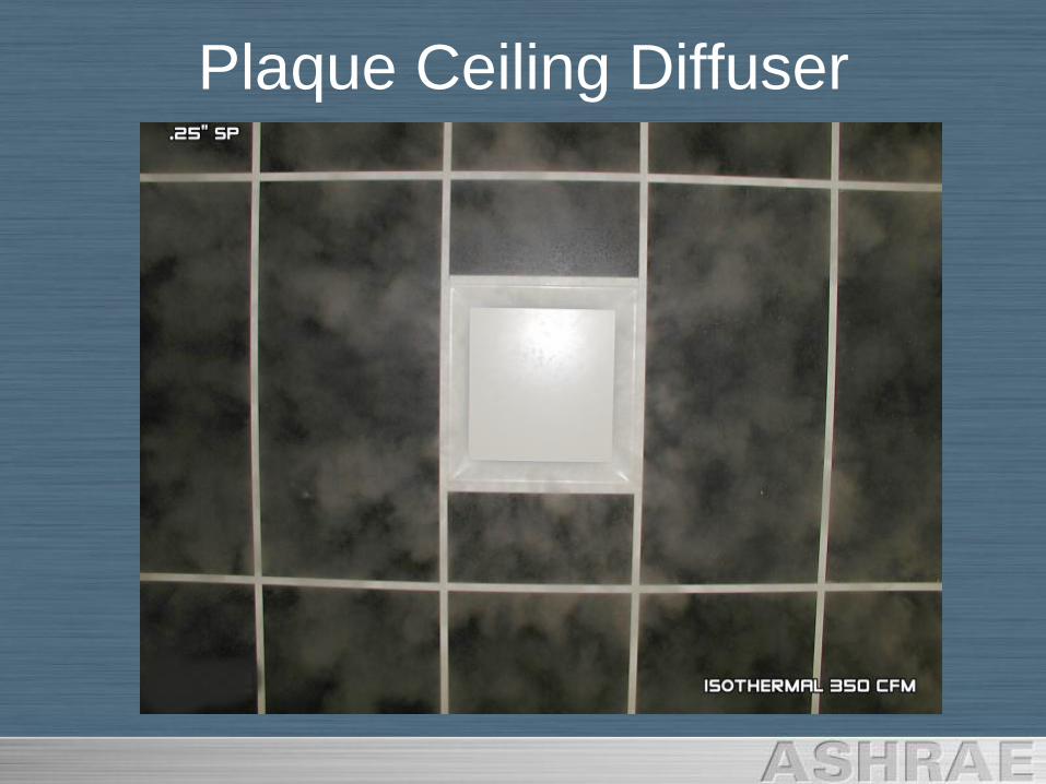
Plaque Ceiling Diffuser
Plaque Ceiling Diffuser
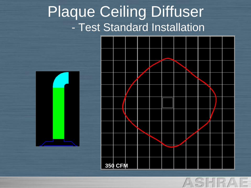
Plaque Ceiling Diffuser- Test Standard Installation
350 CFM
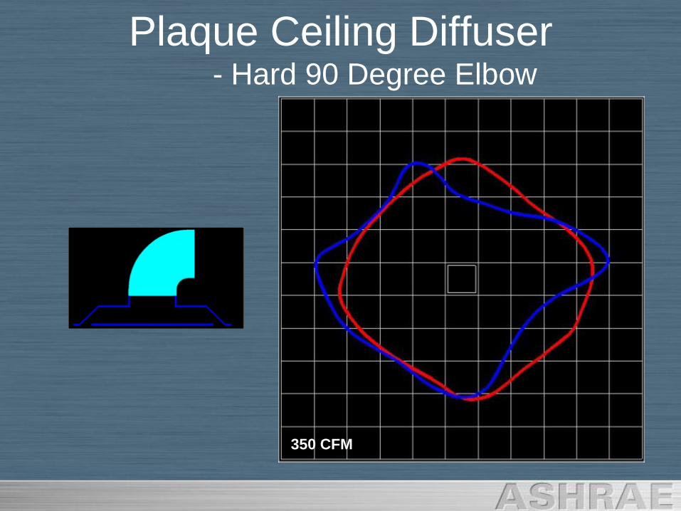
Plaque Ceiling Diffuser- Hard 90 Degree Elbow
350 CFM
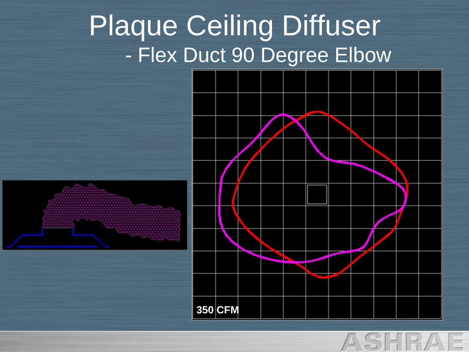
Plaque Ceiling Diffuser- Flex Duct 90 Degree Elbow
350 CFM
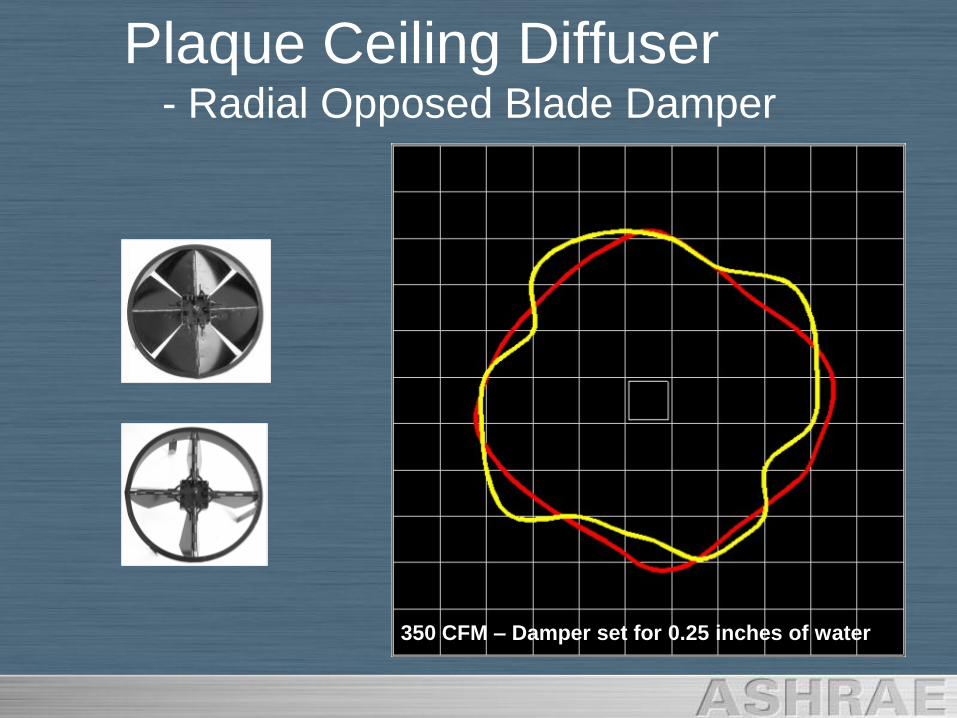
Plaque Ceiling Diffuser- Radial Opposed Blade Damper
350 CFM – Damper set for 0.25 inches of water
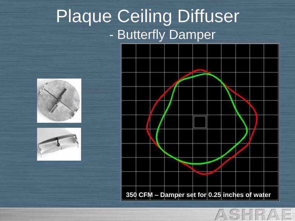
Plaque Ceiling Diffuser- Butterfly Damper
350 CFM – Damper set for 0.25 inches of water
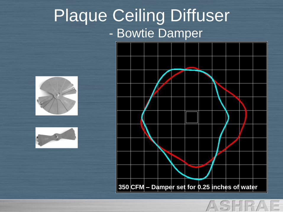
Plaque Ceiling Diffuser- Bowtie Damper
350 CFM – Damper set for 0.25 inches of water
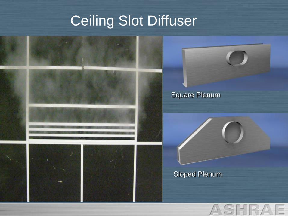
Ceiling Slot Diffuser
Square Plenum
Sloped Plenum
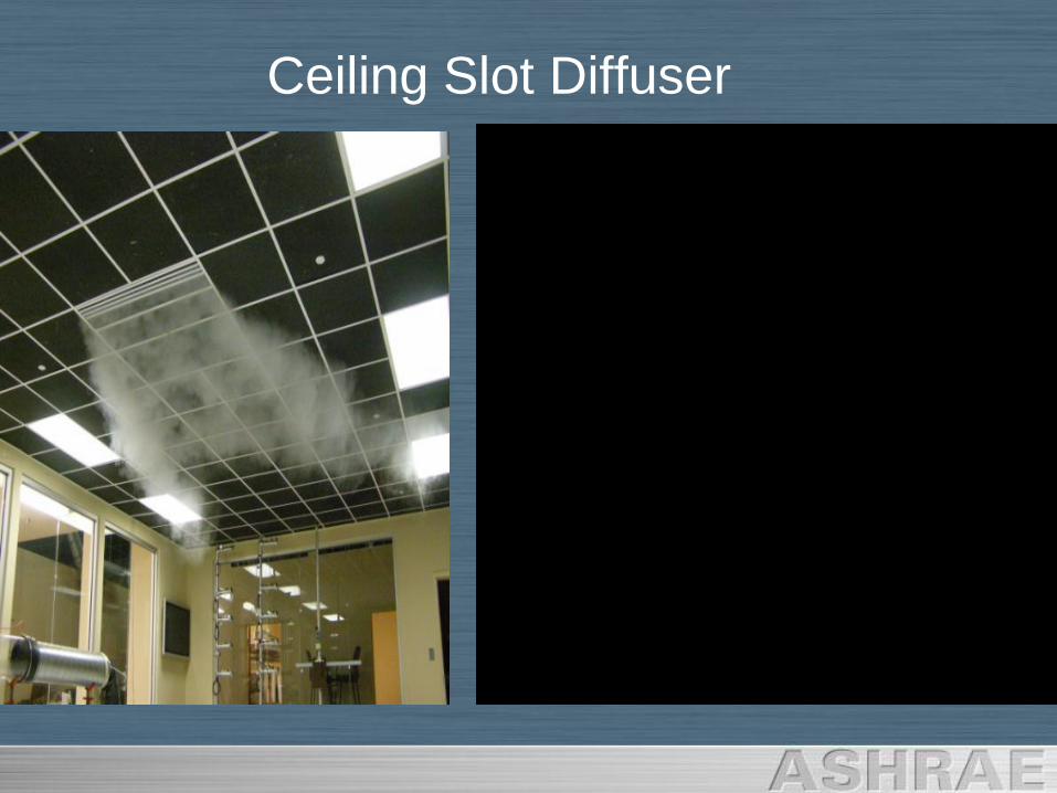
Ceiling Slot Diffuser
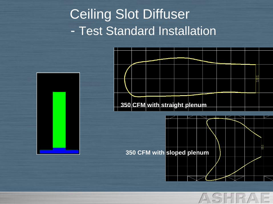
Ceiling Slot Diffuser
- Test Standard Installation
350 CFM with straight plenum
350 CFM with sloped plenum
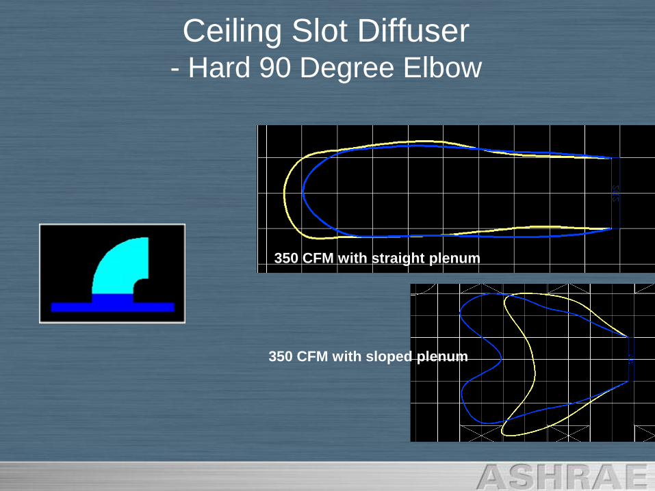
Ceiling Slot Diffuser - Hard 90 Degree Elbow
350 CFM with straight plenum
350 CFM with sloped plenum
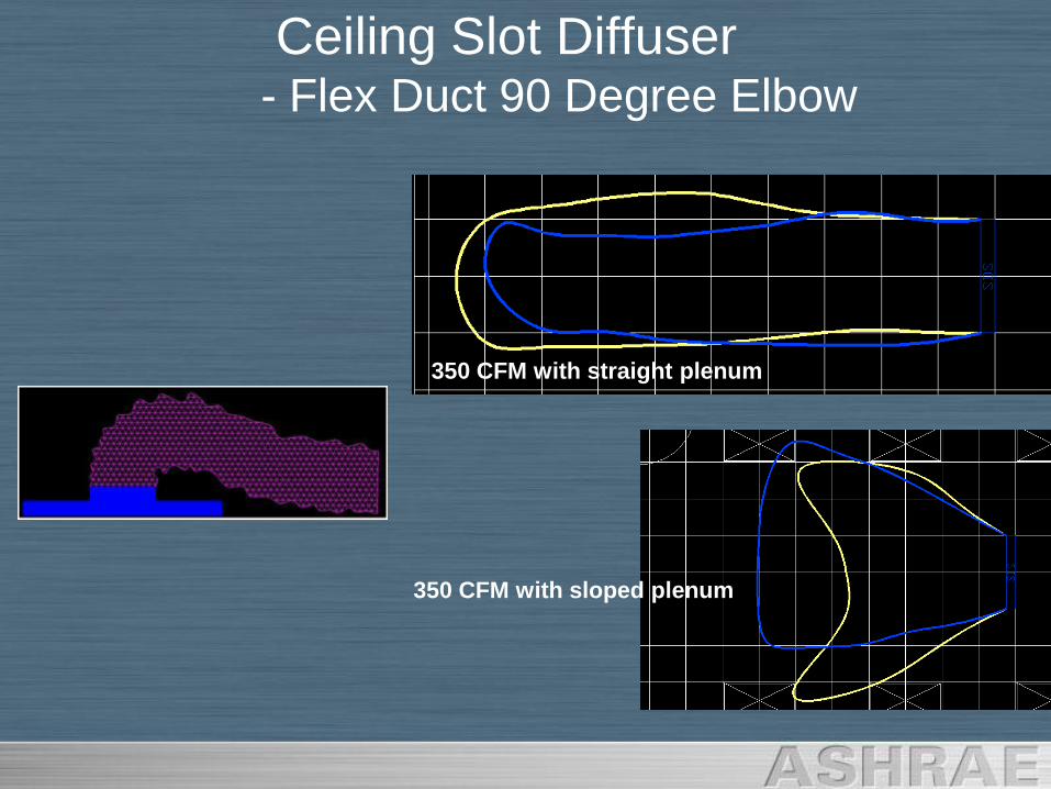
Ceiling Slot Diffuser - Flex Duct 90 Degree Elbow
350 CFM with straight plenum
350 CFM with sloped plenum
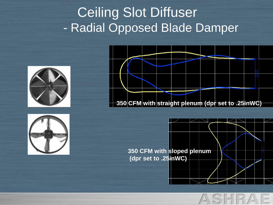
Ceiling Slot Diffuser - Radial Opposed Blade Damper
350 CFM with straight plenum (dpr set to .25inWC)
350 CFM with sloped plenum
(dpr set to .25inWC)
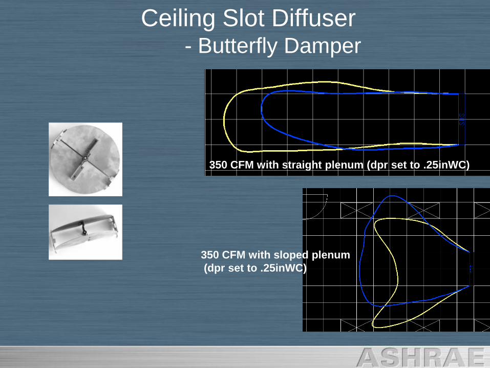
Ceiling Slot Diffuser - Butterfly Damper
350 CFM with straight plenum (dpr set to .25inWC)
350 CFM with sloped plenum
(dpr set to .25inWC)
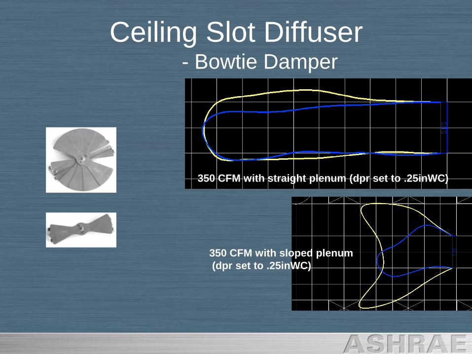
Ceiling Slot Diffuser - Bowtie Damper
350 CFM with straight plenum (dpr set to .25inWC)
350 CFM with sloped plenum
(dpr set to .25inWC)

Workmanship Counts!
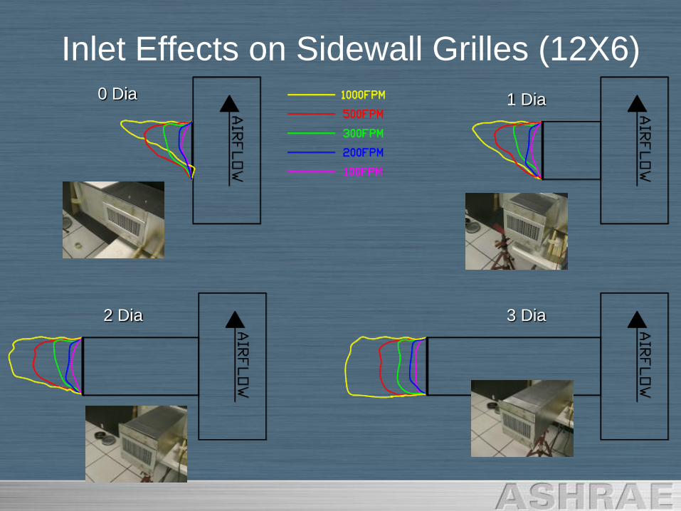
Inlet Effects on Sidewall Grilles (12X6)0 Dia 1 Dia
2 Dia 3 Dia
Sidewall Grille Video (12X6)
0 Dia 1 Dia
2 Dia 3 Dia

GRD Selection & Application
• Terms
• Selection
– Throw
– Sound
• Installation Variations affect Performance
• Inlet Effects