Embed Size (px)
Citation preview

ISOGEN ALIAS
ISOGEN FilesUnderstanding ISOGEN Files
ISOGEN uses data from two sources to produce piping Isometric drawings. The description of thepipeline comes from the Piping Design System in either a Piping Component File (PCF) or anIntermediate Data File (IDF). The user requirement on how that data is to be processed andpresented comes from a set of user definable control files.
This section describes the following ISOGEN operating files.
1. Piping Component Files (PCF).
2. Intermediate Data Files (IDF).
3. The ISOGEN.FLS file.
4. The Message File.
5. Options files.
6. Material List Definition files (MLD).
7. Drawing Definition File (DDF).
8. The Weld Definition File (WDF).
9. User Defined Drawing Frames.
10. Output Data files (Text files for printing or passing data to other systems).
ISOGEN ALIAS
1) Piping Component Files (PCF’s)PCF’s are text files containing component and routing information. They are created by the PipingDesign System extracting information from the piping model and passing this as an input file toISOGEN for the creation of an isometric.
A single PCF can contain the data for a number of pipelines but generally The Piping DesignSystem extracts piping data for single pipelines only and then the ISOGEN system will produceisometrics for one pipeline at a time.
At the end of each run ISOGEN places a copy of the PCF it has processed in theisodir\projname\inputs directory. If the user has access to I-RUN these PCF’s may be processed asa batch for final issue and document control. Other users also find the PCF to be a convenient andeasily understood data file describing the pipeline it represents, and even use it as a source of datato feed other programs. This latter use should, however, be adopted only after consultation withAlias Limited to ensure that future changes in file format do not invalidate the proposed use.
Sample PCF input
Users will not normally need to see the detail in their PCF’s. However, an example PCF for theabove pipeline is shown here for information.
600
600
ISOGEN ALIAS
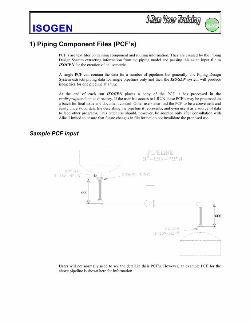
✎ In the interests of brevity, only the shaded start and end sections of the pipeline are shownin the file.
ISOGEN-FILES ISOGEN.FLSUNITS-BORE INCHUNITS-CO-ORDS MMUNITS-BOLT-DIA INCHUNITS-BOLT-LENGTH INCHPIPELINE-REFERENCE 3"-LSA-3250
REVISION 2AREA AR-26APIPING-SPEC SP1NOMINAL-CLASS 150#DATE-DMY 08/11/95PIPELINE-TEMP 150.0
END-CONNECTION-EQUIPMENTCO-ORDS 6000.00 10210.00 1400.00 3CONNECTION-REFERENCE H-152-NZ-6
GASKETEND-POINT 6000.00 10210.00 1400.00 3END-POINT 6000.00 10210.00 1403.00 3PIPING-SPEC SP1ITEM-CODE JFA150R2ERECTION-ITEMBOLTBOLT-DIA 5/8BOLT-LENGTH 3.75BOLT-QUANTITY 4BOLT-ITEM-CODE BAA5/8X3.75ERECTION-ITEM
FLANGEEND-POINT 6000.00 10210.00 1403.00 3END-POINT 6000.00 10210.00 1323.60 3PIPING-SPEC SP1ITEM-CODE FAM150WN40SKEY FLWNFABRICATION-ITEMFLOW 2
PIPEEND-POINT 6000.00 10210.00 1323.60 3END-POINT 6000.00 10210.00 917.30 3PIPING-SPEC SP1WASTE 10.0PLANT-AREA 1ITEM-CODE PAW-40FABRICATION-ITEM
Pipeline Header Data
StartConnectionInformation
Componentdata
Units data
ISOGEN ALIAS
PIPEEND-POINT 9000.00 10210.00 688.70 3END-POINT 9000.00 10210.00 282.40 3PIPING-SPEC SP1WASTE 10.0PLANT-AREA 1ITEM-CODE PAW-40FABRICATION-ITEM
FLANGEEND-POINT 9000.00 10210.00 282.40 3END-POINT 9000.00 10210.00 203.00 3PIPING-SPEC SP1ITEM-CODE FAM150WN40SKEY FLWNFABRICATION-ITEM
GASKETEND-POINT 9000.00 10210.00 203.00 3END-POINT 9000.00 10210.00 200.00 3PIPING-SPEC SP1ITEM-CODE JFA150R2ERECTION-ITEMFLOW 2BOLTBOLT-DIA 5/8BOLT-LENGTH 3.75BOLT-QUANTITY 4BOLT-ITEM-CODE BAA5/8X3.75ERECTION-ITEM
END-CONNECTION-EQUIPMENTCO-ORDS 9000.00 10210.00 200.00 3CONNECTION-REFERENCE H-156-NZ-5
MATERIALSITEM-CODE PAW-40
DESCRIPTION PIPE - API 5L GR B SCH 40ITEM-CODE JFA150R2
DESCRIPTION GASKET - CAF GR A 1/16 THK 150# RFITEM-CODE FAM150WN40
DESCRIPTION FLANGE - WN 150# RF ASTM A105 SCH 40ITEM-CODE BAA5/8X3.75
DESCRIPTION STUD BOLT - CS 5/8 DIA X 3.3/4 LG WITH NUTSITEM-CODE EAM90L40
DESCRIPTION ELBOW - BW 90 DEG LR ASTM A234 GR WPB SCH 40ITEM-CODE VW4
DESCRIPTION VALVE - WEDGEGATE TYPE 26 150# RF
EndConnectionInformation
MaterialDescriptions
ComponentData
ISOGEN ALIAS
Explanatory Notes1) The first line specifies the name of the file used to define the various ISOGEN parameter files,
in this case - ISOGEN.FLS . This is a text file that contains a list of filename pointers to all thevarious ‘external’ files that are read or written to during the execution of ISOGEN, includingthe plot file name.
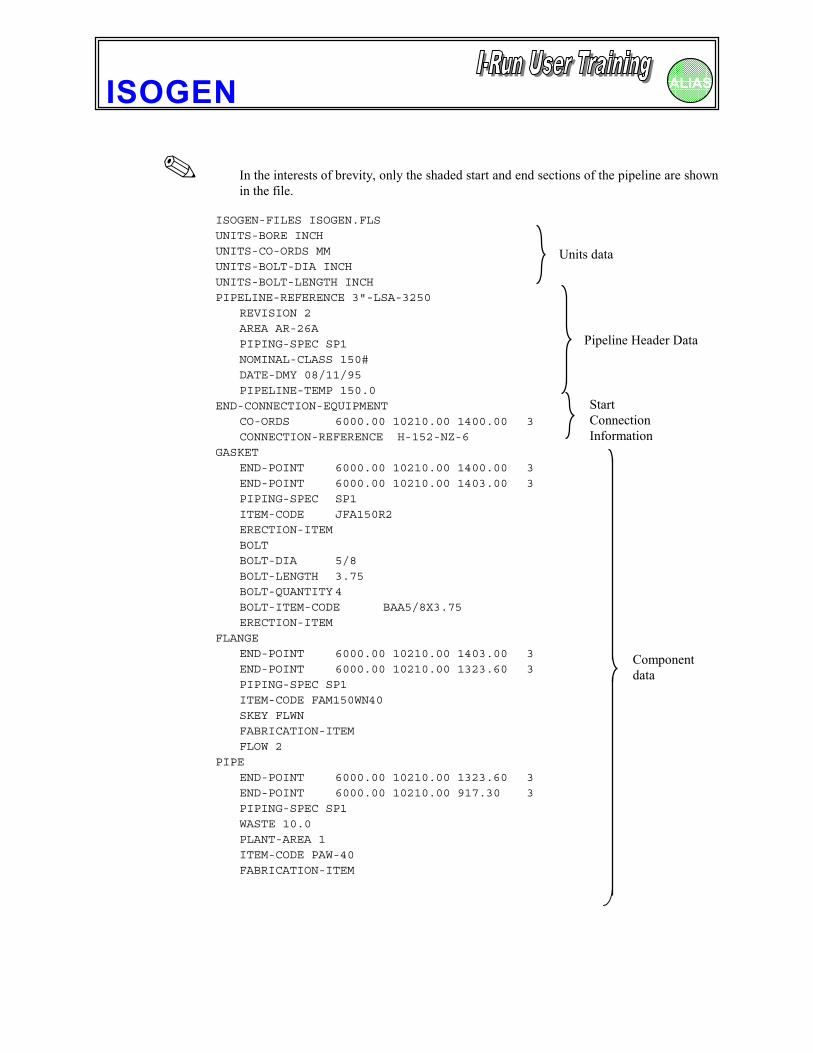
2) As indicated, following the first line, the PCF contains the following information:
♦ Units data
♦ Pipeline Header data
♦ End Connection for start of pipeline
♦ Component data section with an entry for every component in the pipeline
♦ End Connection for end of pipeline
♦ Material Descriptions
ISOGEN ALIAS
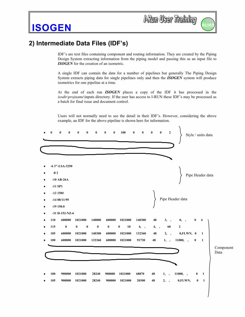
2) Intermediate Data Files (IDF’s)IDF’s are text files containing component and routing information. They are created by the PipingDesign System extracting information from the piping model and passing this as an input file toISOGEN for the creation of an isometric.
A single IDF can contain the data for a number of pipelines but generally The Piping DesignSystem extracts piping data for single pipelines only and then the ISOGEN system will produceisometrics for one pipeline at a time.
At the end of each run ISOGEN places a copy of the IDF it has processed in theisodir\projname\inputs directory. If the user has access to I-RUN these IDF’s may be processed asa batch for final issue and document control.
Users will not normally need to see the detail in their IDF’s. However, considering the aboveexample, an IDF for the above pipeline is shown here for information.
♦ 0 0 0 0 0 0 0 0 100 0 0 0 0 2
♦ -6 3"-LSA-3250
♦ -8 2
♦ -10 AR-26A
♦ -11 SP1
♦ -12 150#
♦ -14 08/11/95
♦ -19 150.0
♦ -31 H-152-NZ-6
♦ 110 600000 1021000 140000 600000 1021000 140300 48 3, , 0, , 0 4
♦ 115 0 0 0 0 0 0 10 4, , 4, , 60 2
♦ 105 600000 1021000 140300 600000 1021000 132360 48 2, , 0,FLWN, 0 1
♦ 100 600000 1021000 132360 600000 1021000 91730 48 1, , 11000, , 0 1
♦ 100 900000 1021000 28240 900000 1021000 68870 48 1, , 11000, , 0 1
♦ 105 900000 1021000 28240 900000 1021000 20300 48 2, , 0,FLWN, 0 1
Style / units data
Pipe Header data
ComponentData
Pipe Header data
ISOGEN ALIAS
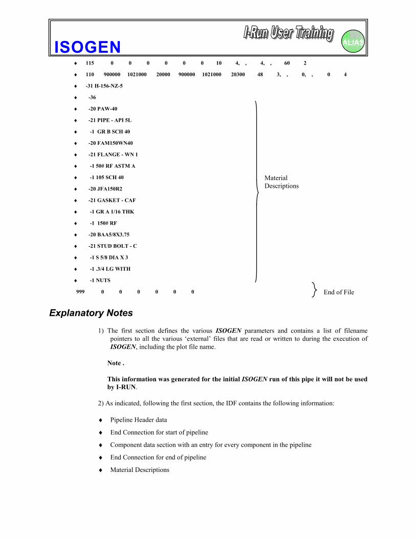
♦ 115 0 0 0 0 0 0 10 4, , 4, , 60 2
♦ 110 900000 1021000 20000 900000 1021000 20300 48 3, , 0, , 0 4
♦ -31 H-156-NZ-5
♦ -36
♦ -20 PAW-40
♦ -21 PIPE - API 5L
♦ -1 GR B SCH 40
♦ -20 FAM150WN40
♦ -21 FLANGE - WN 1
♦ -1 50# RF ASTM A
♦ -1 105 SCH 40
♦ -20 JFA150R2
♦ -21 GASKET - CAF
♦ -1 GR A 1/16 THK
♦ -1 150# RF
♦ -20 BAA5/8X3.75
♦ -21 STUD BOLT - C
♦ -1 S 5/8 DIA X 3
♦ -1 .3/4 LG WITH
♦ -1 NUTS
999 0 0 0 0 0 0
Explanatory Notes1) The first section defines the various ISOGEN parameters and contains a list of filename
pointers to all the various ‘external’ files that are read or written to during the execution ofISOGEN, including the plot file name.
Note .
This information was generated for the initial ISOGEN run of this pipe it will not be usedby I-RUN.
2) As indicated, following the first section, the IDF contains the following information:
♦ Pipeline Header data
♦ End Connection for start of pipeline
♦ Component data section with an entry for every component in the pipeline
♦ End Connection for end of pipeline
♦ Material Descriptions
MaterialDescriptions
End of File
ISOGEN ALIAS
3) The ISOGEN.FLS FileMost of the controls files available to ISOGEN are optional, so an index file called ISOGEN.FLS isused to tell ISOGEN the path and name of each of the control files which are to be used in the currentrun. Each of the isotype sub-directories contains its own ISOGEN.FLS to invoke the relevant controlfiles for the particular type and style of drawing to be produced.
The ISOGEN.FLS file is also used to define the path and name of various output files that ISOGENcan produce in addition to the isometric drawing file, and to declare certain optional data which canbe used during execution.
Each entry in the file consists of a KEYWORD followed by a PATH\FILENAME or a DATA item.eg
MESSAGE isodir\projname\FINAL\ISOGEN.MSGMATERIAL-CONTROL isodir \projname\FINAL\DDRAWINGS\MATERIAL.CTLDRAWING-FRAME isodir \projname\FINAL\FINAL.DGNOPTION-SWITCHES-LONG isodir \projname\FINAL\ALIAS.OPL
✎ The KEYWORD and the associated data must be separated by one or more spaces.“TAB” characters are not allowed and will cause the KEYWORD to be ignored.
The “create new project” utility will copy the standard ISOGEN.FLS for each isotype into theappropriate sub-directories and include the correct path for the chosen project name in each case. Ifyou need to add a reference to any further control or output file, it is essential that the full path and filename is included to point to where the control file is located. The ISOGEN.FLS is an ASCII text fileand it can be modified using any suitable text editor such as MS Windows NOTEPAD.
ISOGEN ALIAS
4) The Message FileEvery time ISOGEN runs it writes a message to a file whose name and path are specified in theISOGEN.FLS file. These messages are only created for diagnostic purposes and as long as everythingworks normally these will be of no interest of no interest to the user.
If ISOGEN runs but does not produce valid output, you should save a copy of the Message Filetogether with the PCF / IDF and any output files which have been created. These will help theISOGEN support staff diagnose the problem.
ISOGEN ALIAS
5) Options Files.ISOGEN contains a large number of variable features. For example:
1. Isometric type
2. Bill of Materials position on the isometric
3. Dimensional units
4. Isometric drawing size
5. Cut pipe list - ON/OFF
6. Line weight and symbol size
etc.
These and other features are all controlled by settings made by the user and held in the OptionsFile. Each isotype installed for a project will in fact have its own Options File containing thesettings relevant for the particular style and content.
Each Options File contains a total of 140 switches, many of which have several positions. A singleOption Switch controls most features in numeric form, but some of the more advanced featuresneed two.
Like most other ISOGEN control files, the Options File is a text file that may be created and editedwith any standard text editor but to simplify the process of making changes to settings, an OptionsSwitch Editor is provided for use with ISOGEN. To change Option Switches simply click on theEdit button in the Project Manager. Go to the appropriate page(s) for the switches you wish tochange and select the new settings. Then save the file and you are ready to use it.
The Options File ContentsThe Options File name is identified as file OPTION-SWITCHES-LONG in the FLS file e.g.ALIAS.OPL.
Each Options File consists of a header followed by 140 lines with one Option Switch per line.Each line can include a comment, signified by a !
The 140 different options are specified in a vertical structure on a 1 line per Option Switch basis.
Sample file layoutSWITCH SWITCHNUMBER SETTING------ -------
1 0 ! Plot File Length2 1 ! Cut Pipe List3 0 ! Cut Marks
Header.These 3 lines plus oneblank line are mandatory.
ISOGEN ALIAS
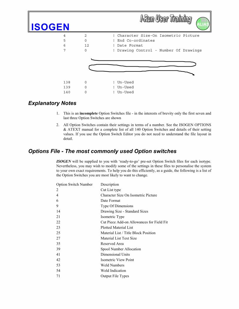
4 2 ! Character Size-On Isometric Picture5 0 ! End Co-ordinates6 12 ! Date Format7 0 ! Drawing Control - Number Of Drawings
138 0 ! Un-Used139 0 ! Un-Used140 0 ! Un-Used
Explanatory Notes1. This is an incomplete Option Switches file - in the interests of brevity only the first seven and
last three Option Switches are shown
2. All Option Switches contain their settings in terms of a number. See the ISOGEN OPTIONS& ATEXT manual for a complete list of all 140 Option Switches and details of their settingvalues. If you use the Option Switch Editor you do not need to understand the file layout indetail.
Options File - The most commonly used Option switchesISOGEN will be supplied to you with ‘ready-to-go’ pre-set Option Switch files for each isotype.Nevertheless, you may wish to modify some of the settings in these files to personalise the systemto your own exact requirements. To help you do this efficiently, as a guide, the following is a list ofthe Option Switches you are most likely to want to change.
Option Switch Number Description2 Cut List type4 Character Size On Isometric Picture6 Date Format9 Type Of Dimensions14 Drawing Size - Standard Sizes21 Isometric Type22 Cut Piece Add-on Allowances for Field Fit23 Plotted Material List25 Material List / Title Block Position27 Material List Text Size35 Reserved Area39 Spool Number Allocation41 Dimensional Units42 Isometric View Point53 Weld Numbers54 Weld Indication71 Output File Types
ISOGEN ALIAS
73 Part Number Box Style75 Weld Number Box Style
ISOGEN ALIAS
6) Material List Definition file (MLD)This file is only needed if you wish to utilise the User Defined Material List (Material List is alsoknown as Bill of Material or BOM ).
The following options are available:-
1. Two further Material List styles - in addition to the standard one
2. The ability to transfer components from their standard category to another one
3. Add Remarks - taken from a user-defined file of standard Remarks
4. Specify a Material Control File with user defined content and layout
Examples of the different Material List Styles
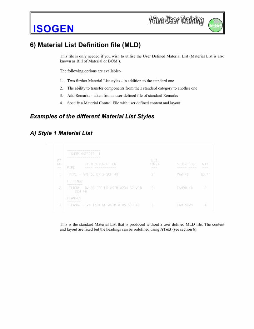
A) Style 1 Material List
This is the standard Material List that is produced without a user defined MLD file. The contentand layout are fixed but the headings can be redefined using AText (see section 6).
ISOGEN ALIAS
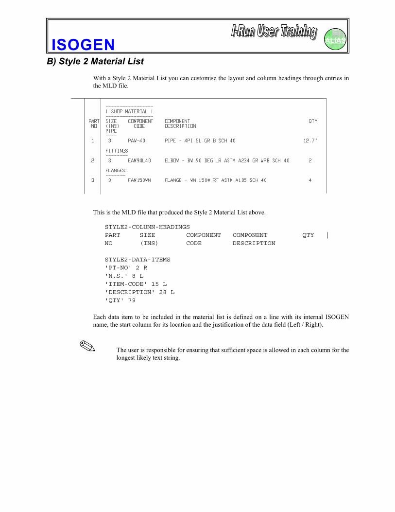
B) Style 2 Material ListWith a Style 2 Material List you can customise the layout and column headings through entries inthe MLD file.
This is the MLD file that produced the Style 2 Material List above.
STYLE2-COLUMN-HEADINGSPART SIZE COMPONENT COMPONENT QTY |NO (INS) CODE DESCRIPTION
STYLE2-DATA-ITEMS'PT-NO' 2 R'N.S.' 8 L'ITEM-CODE' 15 L'DESCRIPTION' 28 L'QTY' 79
Each data item to be included in the material list is defined on a line with its internal ISOGENname, the start column for its location and the justification of the data field (Left / Right).
✎ The user is responsible for ensuring that sufficient space is allowed in each column for thelongest likely text string.
ISOGEN ALIAS
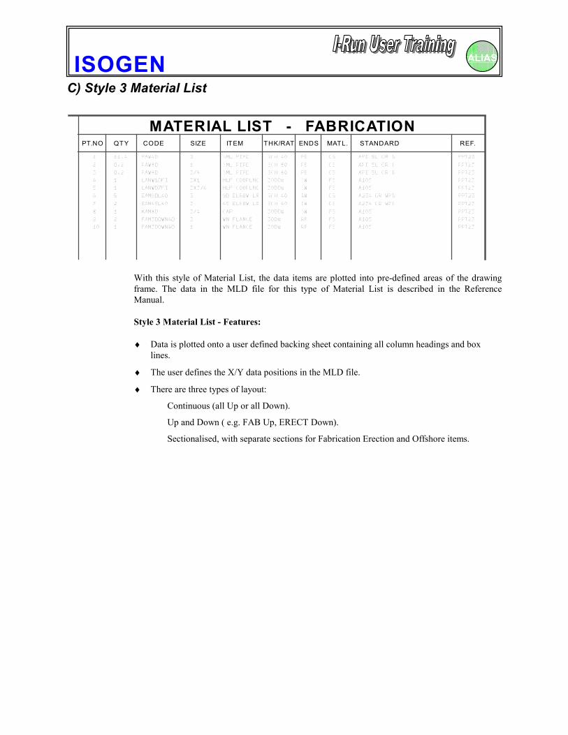
C) Style 3 Material List
MATERIAL LIST - FABRICATION PT.NO QTY CODE SIZE ITEM THK/RAT ENDS MATL. STANDARD REF.
With this style of Material List, the data items are plotted into pre-defined areas of the drawingframe. The data in the MLD file for this type of Material List is described in the ReferenceManual.
Style 3 Material List - Features:
♦ Data is plotted onto a user defined backing sheet containing all column headings and boxlines.
♦ The user defines the X/Y data positions in the MLD file.
♦ There are three types of layout:
Continuous (all Up or all Down).
Up and Down ( e.g. FAB Up, ERECT Down).
Sectionalised, with separate sections for Fabrication Erection and Offshore items.
ISOGEN ALIAS
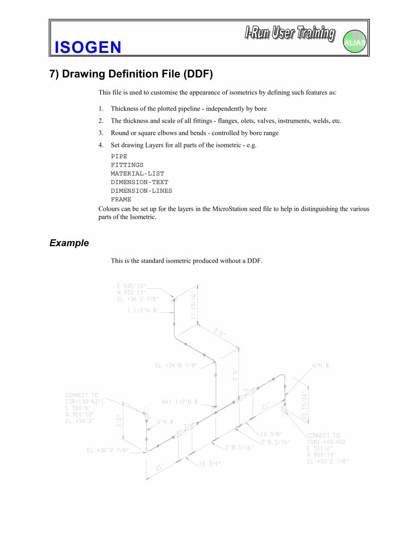
7) Drawing Definition File (DDF)This file is used to customise the appearance of isometrics by defining such features as:
1. Thickness of the plotted pipeline - independently by bore
2. The thickness and scale of all fittings - flanges, olets, valves, instruments, welds, etc.
3. Round or square elbows and bends - controlled by bore range
4. Set drawing Layers for all parts of the isometric - e.g.PIPEFITTINGSMATERIAL-LISTDIMENSION-TEXTDIMENSION-LINESFRAME
Colours can be set up for the layers in the MicroStation seed file to help in distinguishing the variousparts of the Isometric.
ExampleThis is the standard isometric produced without a DDF.
ISOGEN ALIAS
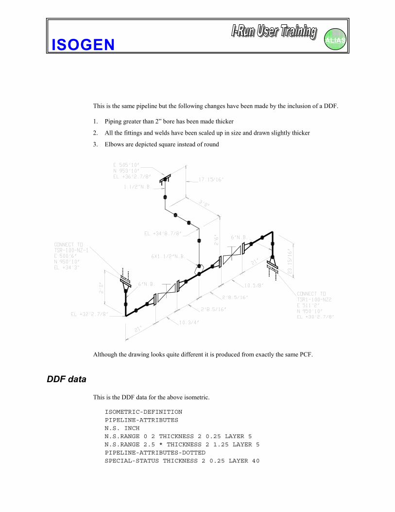
This is the same pipeline but the following changes have been made by the inclusion of a DDF.
1. Piping greater than 2” bore has been made thicker
2. All the fittings and welds have been scaled up in size and drawn slightly thicker
3. Elbows are depicted square instead of round
Although the drawing looks quite different it is produced from exactly the same PCF.
DDF data
This is the DDF data for the above isometric.
ISOMETRIC-DEFINITIONPIPELINE-ATTRIBUTESN.S. INCHN.S.RANGE 0 2 THICKNESS 2 0.25 LAYER 5N.S.RANGE 2.5 * THICKNESS 2 1.25 LAYER 5PIPELINE-ATTRIBUTES-DOTTEDSPECIAL-STATUS THICKNESS 2 0.25 LAYER 40
ISOGEN ALIAS
PIPELINE-CONTINUATION THICKNESS 1 0.25 LAYER 40FITTINGS-GENERALN.S. INCHN.S.RANGE 0 2 THICKNESS 2 0.25 LAYER 5 SCALE 150N.S.RANGE 2.5 * THICKNESS 2 1.25 LAYER 5 SCALE 150FITTINGS-SPECIALINSTRUMENTS THICKNESS 2 0.30 LAYER 10 SCALE 120VALVES THICKNESS 2 0.30 LAYER 10 SCALE 120MISC-COMPONENTS THICKNESS 2 0.30 LAYER 10 SCALE 120NOZZLE THICKNESS 2 0.6 LAYER 10 SCALE 120FLANGES THICKNESS 2 0.6 LAYER 10 SCALE 120WELDS THICKNESS 4 0.35 LAYER 35 SCALE 100BEND/ELBOW-REPRESENTATIONBEND ROUNDELBOW SQUAREMISC-ITEMSDIMENSION-TEXT LAYER 20DIMENSION-LINES LAYER 25MATERIAL-LIST LAYER 30FRAME LAYER 31FRAME-TEXT LAYER 31ISO-TEXT LAYER 32LAYER-NAMES5 'PIPE'10 'INST'20 'DIMTEXT'25 'DIMLINES'30 'MATLIST'31 'FRAME'32 'ISOTEXT'35 'WELDS'40 'DOTTED'
Full details of the allowable content of the DDF are given in the Reference Manual.
The ISOGEN installation includes a default DDF for each isotype. These can be customised asrequired by the user. A DDF editor is available to users of ISOGEN this is activated through theProject Manager.
ISOGEN ALIAS
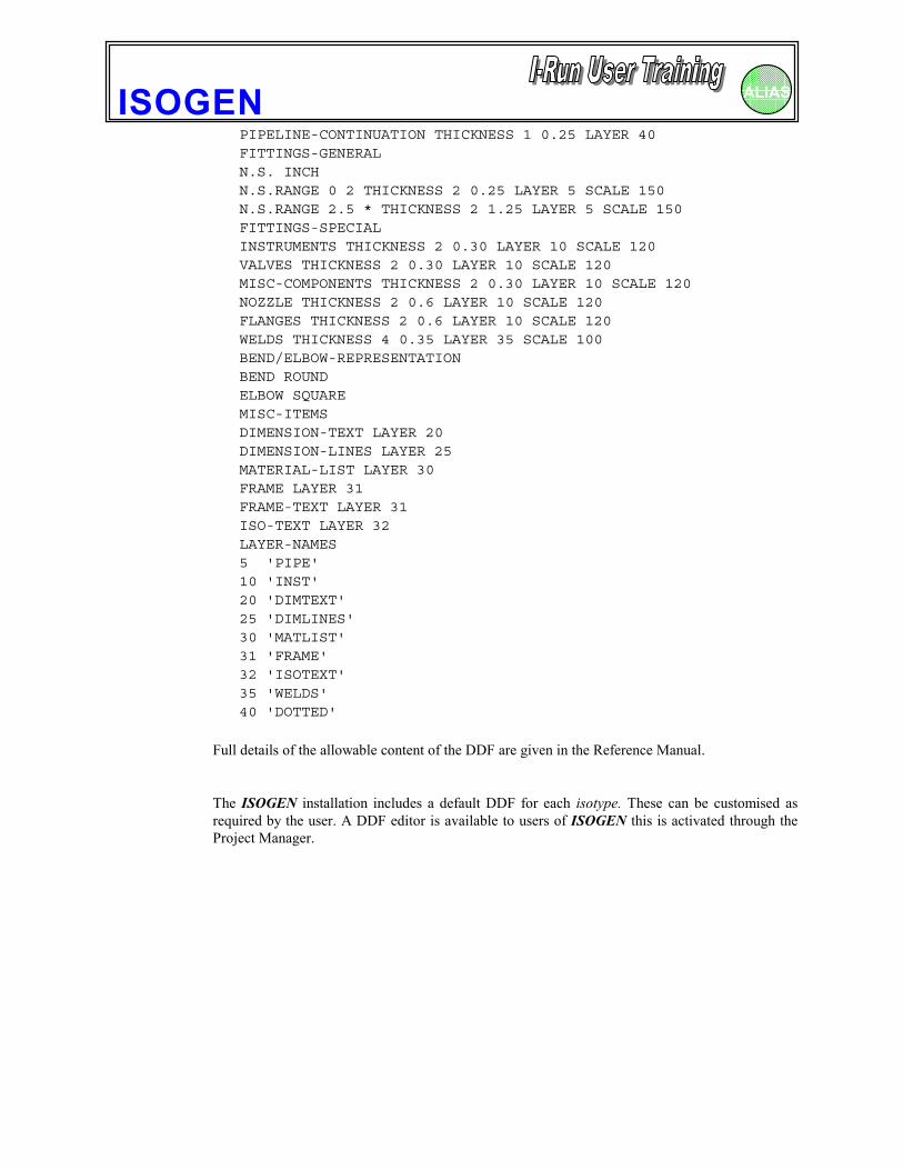
8) The Welding Definition File (WDF)Detailed Weld information may be shown on the isometric in a plotted Weld Table like the oneshown here. The table is user definable and will often contain spaces for data to be filled in laterduring fabrication or erection as well as columns for data contained within the PCF. The WeldTable (sometimes known as the Weld Box) is placed in the bottom right hand corner of the plottedarea of the drawing. Examples of Weld Tables can be seen in the samples included in the\SAMPLEPROJ\SAMPLEPROJECT\FINAL-WELD-BOX directory on installation.
To generate a plotted Weld Table on the isometric, you must supply relevant information in aWelding Definition File (WDF) which must be referenced in the ISOGEN.FLS against thekeyword WELDING-DEFINITION.
Welding Definition File dataThe data in the file WELDING.WDF to produce the above Weld Table output looks like this :-
WELD-BOX-HEADINGSWELD | SIZE | WELD | WELD |No | INS | TYPE | CATEGORY |
WELD-BOX-DATA-ITEMS'WELD-NO' 5 R'N.S.' 10 L'WELD-TYPE' 17 L'WELD-CAT' 26 L
For full details of the content of the WDF see the Reference manual.
ISOGEN ALIAS
9) User Defined Drawing FramesWhen you installed ISOGEN a pre-defined drawing frame was loaded as a seed file for eachisotype. Although these can be used as required, it is most likely, at some time you will want tomake your own frames and have your isometrics plotted onto them. User Defined Drawing Framesare drawings created in the format to suit your Piping Design environment. eg MicroStation DesignFiles (DGN) and DXF or DWG files for AutoCAD. You can therefore customise the frame toinclude information such as a company logo and other symbols and text. Also, the layouts may bedesigned to suit your exact requirements. These Design Files are then used as seed files orunderlay’s during the isometric production phase.
Actions required to modify a User Defined Drawing Frame1. Use MicroStation or AutoCAD to modify the appropriate seed file as required.
2. Modify the associated AText file to change or suppress ISOGEN text as required. (SeeAdvanced Features for control of AText.)
3. Identify the location on the drawing for any new or revised data items and modify the TextPosfile accordingly.
4. Add records to the ISOGEN.FLS to specify:
Include a record to point to the Drawing Frame file name :
DRAWING-FRAME Drawing_Frame_Name.DGN
Include a record pointing to the file that contains your TextPos data.
POSITIONED-TEXT Text_Position_Name.POS
Include a record pointing to the file that contains your AText data.
ALTERNATIVE-TEXT AText_Name.ALT
In the case of AutoCAD a DXF drawing frame can be used as an “underlay” into which theisometric is merged as it is created by ISOGEN but this adds significantly to both processing timeand to the size of the drawing files created. A preferable alternative is to create the drawing frameas a DWG file and to create the Isometrics as a DXF without a DRAWING-FRAME record in theISOGEN.FLS. The DWG file can then be loaded into AutoCAD and the DXF imported into it forplotting or the addition of data missing from the PCF.
✎ Please note that when working in a MicroStation environment the Design File for eachisotype must be called isotype.DGN. eg for the isotype FINAL it will be calledFINAL.DGN, and for the isotype CHECK it will be called CHECK.DGN. For othersystems you may use any valid file name as long as you specify it correctly in theISOGEN.FLS record.
ISOGEN ALIAS
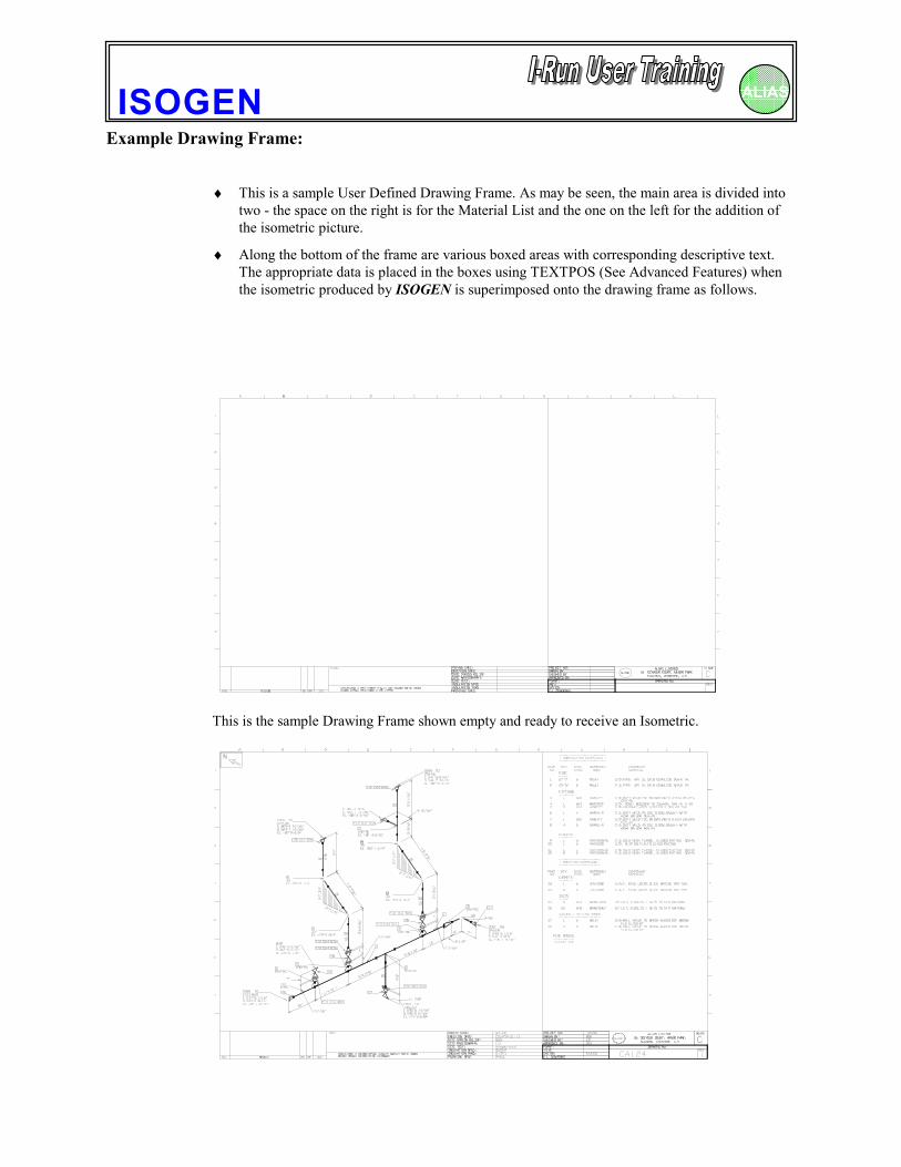
Example Drawing Frame:
♦ This is a sample User Defined Drawing Frame. As may be seen, the main area is divided intotwo - the space on the right is for the Material List and the one on the left for the addition ofthe isometric picture.
♦ Along the bottom of the frame are various boxed areas with corresponding descriptive text.The appropriate data is placed in the boxes using TEXTPOS (See Advanced Features) whenthe isometric produced by ISOGEN is superimposed onto the drawing frame as follows.
This is the sample Drawing Frame shown empty and ready to receive an Isometric.

ISOGEN ALIAS
This is the Final Isometric superimposed onto the Drawing Frame.
ISOGEN ALIAS
10) Output data filesIn addition to producing isometrics, ISOGEN can also output information to text files for printingor use as data input for other systems. The types of files that may be produced in this way include:
1. Printed Material List (BOM). This may be either the standard default version oralternatively, with a user defined content and layout and may be created either in addition to orinstead of the Material List on the Iso.
2. Material Control File. With user defined content and format.
3. Weld Summary File. With user defined content and format.
Printed Material List (BOM)1. To obtain a standard “Style 1” printed Material List for a pipeline all you have to do is to
include an entry in the ISOGEN.FLS defining the name of the file to be created. eg
PRINTED-MATERIAL-LIST BOM.MAT
The file BOM.MAT will then be created and data will be appended to it for each pipelineprocessed by Personal ISOGEN.
2. To obtain a user defined “Style 2” printed Material List you must :
a) make a PRINTED-MATERIAL-LIST ‘filename’ entry in the ISOGEN.FLS file as above,
and
b) add a PRINTED-MATERIAL-LIST-TITLES section to your MLD file for the printedpage titles. The remainder of the Material List control data will be taken from STYLE2-COLUMN-HEADINGS and STYLE2-DATA-ITEMS information in the MLD file, whichmeans the printed Material List will look just like the plotted one.
✎ If required the Material List may be suppressed such that it does not appear on thedrawing by setting Option Switch 23. (See Reference Manual.)
Material Control FileTo obtain a user defined Material Control output file you must:-
a) Include an entry in the ISOGEN.FLS defining the name of the file to be created. eg
MATERIAL-CONTROL MATLC.MACThe file MATLC.MAC will be created and data will be appended to it for every pipelineprocessed by ISOGEN.
and
ISOGEN ALIAS
b) add PRINTED-M/C-COLUMN-HEADINGS for the printed page titles and PRINTED-M/C-DATA-ITEMS sections to your MLD file.
Sample Material Control output filePIPELINE DRG MAIN SECREF NO DESCRIPTION CODE BORE BORE QTY-------- --- ----------- ----- ---- ---- ---3"-LSA-3250 1 PIPE - API 5L GR B SCH 40 PAW-40 3 3 12.7'3"-LSA-3250 1 ELBOW - BW 90 DEG LR ASTM A234 GR WPB SCH 40 EAM90L40 3 3 23"-LSA-3250 1 FLANGE - WN 150# RF ASTM A105 SCH 40 FAM150WN 3 3 43"-LSA-3250 1 GASKET - CAF GR A 1/16 THK 150# RF JFA150R2 3 3 43"-LSA-3250 1 STUD BOLT - CS 5/8 DIA X 3.3/4 LG WITH NUTS BAA5/8X3 5/8 5/8 163"-LSA-3250 1 VALVE - WEDGEGATE TYPE 26 150# RF VW4 3 3 1
Material Control data required in the MLD file to produce the preceding output :-MATERIAL-CONTROL-FILEPRINTED-M/C-COLUMN-HEADINGSPIPELINE DRG MAIN SECREF NO DESCRIPTION CODE BORE BORE QTY-------- --- ----------- ---- ---- ---- ---PRINTED-M/C-DATA-ITEMS
'PIPELINE-REFERENCE' 2 L
'DRG' 15 L
'DESCRIPTION' 20 L
'ITEM-CODE' 66 L
'N.S.' 77 L
'N.S.SEC.' 84 L
'QTY' 92 N
See the Reference Manual for full details of the required entries in the MLD.
Weld Summary FileA Weld Summary File can be created either in “Append” mode whereby data is added to the fileeach time ISOGEN is run, or in “Overwrite” mode whereby a new file is created each time.
✎ In the case of “Overwrite” files the user must move or rename each file as the same namewill be used for each run.
To obtain a user defined Weld Summary file you must:
a) Include an entry in the ISOGEN.FLS defining the name and type of the file to be created.eg
WELD-SUMMARY-OVERWRITE WELDSUM.WSOor WELD-SUMMARY-APPEND WELDSUM.WSA
and
b) add a section to the Welding Definition File (WDF) to define the printed output file.
ISOGEN ALIAS
Sample Weld Summary printed output file.WELD SUMMARY PAGE 1PIPELINE REF3"-LSA-3375 ISSUE 2PROJECT NO PROJ AREA AR-26APIPING SPEC SP1 DATE 14/11/95
WELD WELD WELDNO CAT SIZE TYPE----- ------ ------ ------1 S 3" BW2 S 3" BW3 F 3" BW4 S 3" BW5 S 3" BW6 F 3" BW7 S 3" BW8 S 3" BW
Entry required in the WDF to produce the preceding output:WELD-SUMMARY-TITLES
WELD SUMMARY PAGE ''PIPELINE REF '-6' ISSUE '-8'PROJECT NO '-9' PROJ AREA '-10'PIPING SPEC '-11' DATE '-14''Blank'WELD-SUMMARY-COLUMN-HEADINGSWELD WELD WELDNO CAT SIZE TYPE---- ---- ---- ----WELD-SUMMARY-DATA-ITEMS'WELD-NO' 2'WELD-CAT' 9'N.S.' 16'WELD-TYPE' 23