Embed Size (px)
Citation preview
�����������������������
���������������� ������ ���������������������������������
��������������� �������������
� ��������
����
200 KIASTrimmed
1,000 ft1 min
150
180
120
Aircraft heading 090
240240
090
090
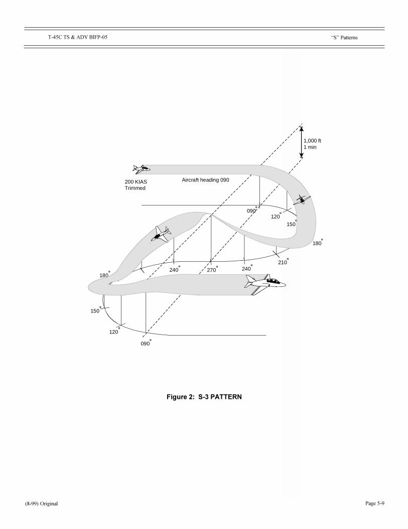
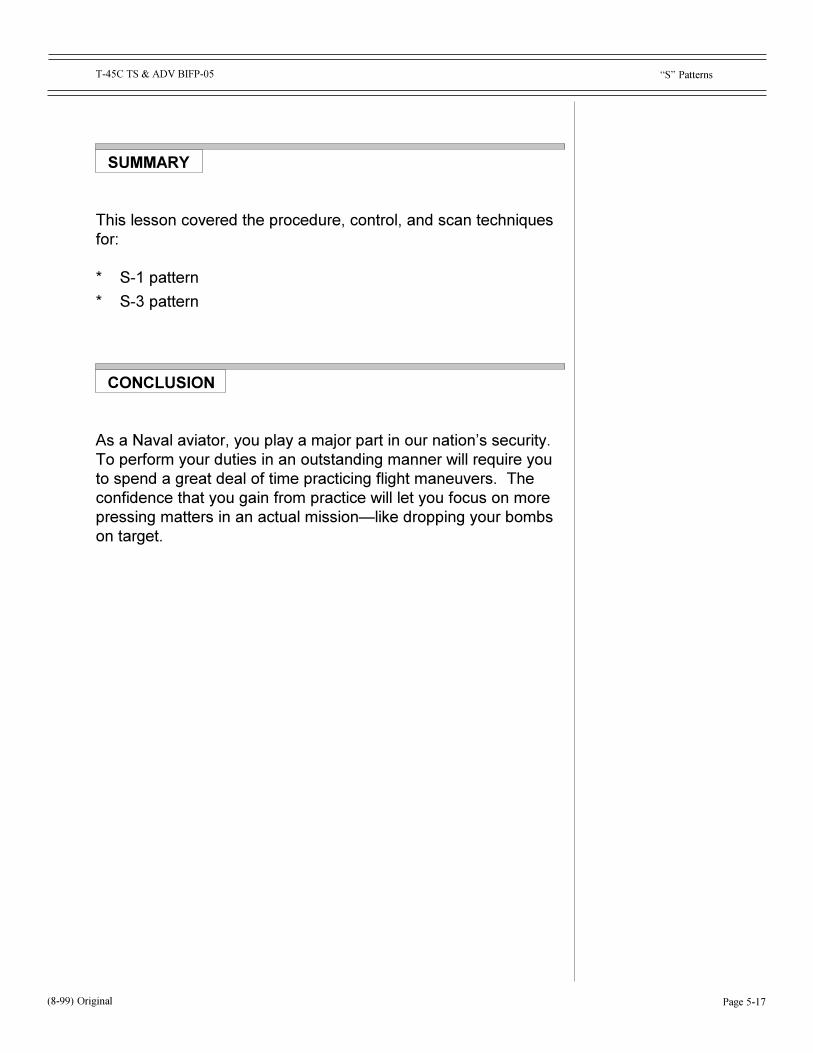
S-3 PATTERN
150
180
210270
120

CHANGE DATENUMBER ENTERED CHANGE DESCRIPTION INITIALS
i(4-01) Original
T-45C FLIGHT SUPPORT LECTURE GUIDE
CHANGE SUMMARY PAGE

THIS PAGE INTENTIONALLY LEFT BLANK.
ii (4-01) Original

EFFECTIVE PAGEPAGES NUMBERS
EFFECTIVE PAGEPAGES NUMBERS
iii
T-45C BIFP Lesson Guide List of Effective Pages
LESSON GUIDELIST OF EFFECTIVE PAGES
FRONT MATTEROriginal i thru iv
TS & ADV BIFP-02Original 2-i thru 2-iiOriginal 2-1 thru 2-14
TS & ADV BIFP-03Original 3-i thru 3-iiOriginal 3-1 thru 3-10
TS & ADV BIFP-04Original 4-i thru 4-iiOriginal 4-1 thru 4-26
TS & ADV BIFP-05Original 5-i thru 5-iiOriginal 5-1 thru 5-18
TS & ADV BIFP-09Original 9-i thru 9-iiOriginal 9-1 thru 9-32
(8-99) Original

THIS PAGE INTENTIONALLY LEFT BLANK.
iv
T-45C BIFP Lesson Guide List of Effective Pages
(8-99) Original
T-45C TS & ADV BIFP-02 Introduction to Basic Instruments
Page 2-i
COURSE/STAGE: T-45C TS & ADV Basic Instruments Flight Procedures
LESSON TITLE: Introduction to Basic Instruments
LESSON IDENTIFIER: T-45C TS & ADV BIFP-02
LEARNING ENVIRONMENT: CAI
ALLOTTED LESSON TIME: 0.7 hr
TRAINING AIDS:
* FiguresFig 1: Instrument Locations
STUDY RESOURCES:
* NATOPS Instrument Flight Manual, NAVAIR 00-80T-112* T-45C Instrument FTI
LESSON PREPARATION:
Read:* Chapters 13, 14, 15, and 16 in the NATOPS Instrument Flight Manual,
NAVAIR 00-80T-112
REINFORCEMENT: N/A
EXAMINATION:
The objectives in this lesson will be tested in TS and ADV BIFP-10X.
LESSON GUIDE
(8-99) ORIGINAL

T-45C TS & ADV BIFP-02 Introduction to Basic Instruments
THIS PAGE INTENTIONALLY LEFT BLANK.
Page 2-ii
T-45C TS & ADV BIFP-02
Page 2-1(8-99) Original
Introduction to Basic Instruments
LESSON OBJECTIVES
1.4.5.3.1.3Identify the location, purpose, and function of the flight controlinstruments
1.4.5.3.1.2Identify the location, purpose, and function of the flight performanceinstruments
1.4.5.3.1.4Identify the location, purpose, and function of the flight positioninstruments
2.5.12.1.1Recall instrument scan procedures/techniques
2.7.8Demonstrate procedures for entering instrument mission datainto display system
T-45C TS & ADV BIFP-02
Page 2-2 (8-99) Original
Introduction to Basic Instruments
MOTIVATION
You should gain a sound understanding of basic instrument flyingearly in your training. The Basic Instrument lessons that you areabout to take will provide you with the necessary information youneed to master the complexities of instrument flight.
This lesson covers the location, purpose, and use of the cockpitinstruments and how to scan them in the most efficient matter. Laterin the curriculum, you will learn to apply this information to operatesafely in low visibility environments.
OVERVIEW
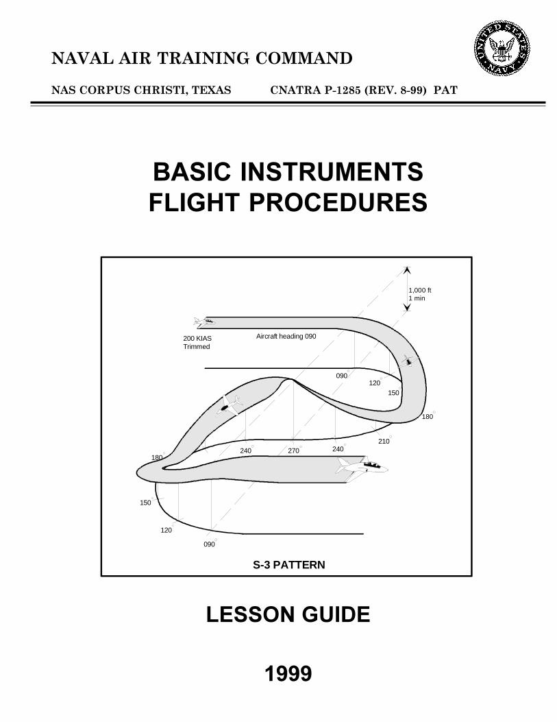
This lesson provides an overview to prepare you for using basicinstruments. Later study sessions and hands-on lessons willaddress transitions, instrument turns, �S� patterns, TACAN/VORprocedures, instrument failures, partial panel techniques, stalls andunusual attitudes.
In this lesson, we will study:
* Control instruments (attitude)* Control instruments (power)* Performance instruments* Position instruments* Basic instrument scan* Entering instrument mission data
As you move through the lesson, note that some instruments havemultiple functions and, therefore, appear in two or more categories(e.g., the ADI).
T-45C TS & ADV BIFP-02
Page 2-3(8-99) Original
Introduction to Basic Instruments
PRESENTATION
LESSON NOTES
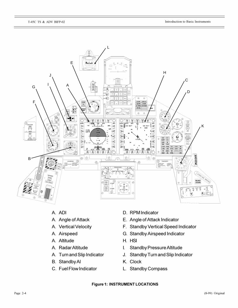
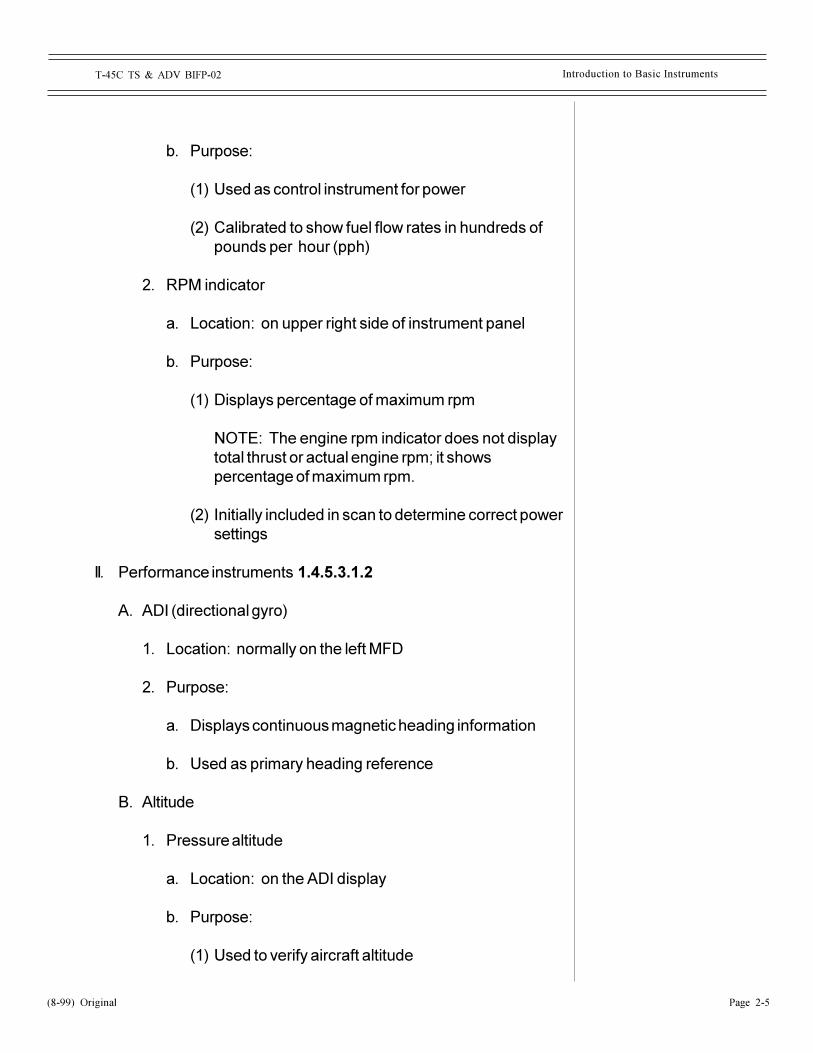
Figure 1 contains a cockpit diagram with the placement of allflight instru-ments mentioned in this lesson. Please refer to it asnecessary for finding the location of these instruments.
I. Control instruments 1.4.5.3.1.3
A. Attitude instruments
1. Attitude director indicator (ADI)
a. Location: normally on the left MFD
b. Purpose: primarily source of pitch, bank, and headinginformation
2. Standby attitude indicator
a. Location: left of the left MFD
b. Purpose:
(1) Used as backup gyro if ADI is disabled
(2) Used as cross-check of main ADI
B. Power instruments
1. Fuel flow indicator
a. Location: on upper right side of instrument panel
Fig 1: InstrumentLocations
T-45C TS & ADV BIFP-02
Page 2-4 (8-99) Original
Introduction to Basic Instruments
TAKEOFF
CANOPYHARNESSSE A T
CONTR AUGANTI-SKIDFLAPS / SL A TSTRIM
+
LANDINGHARNESSSPD BRAKESANTI-SKID
+
GEARFLAPS / SL A TSHOOK
CLI MB
DI VE
TOC
A G E
P
ULL
21.5
0
.5
1 24
6
4UP
DOWN
1000 FT. PER MIN.
0 1
2
346
7
9
2992
0000
ALTIN HG
KNOTSx 100
.6
1
1.5
23
4
56
78
+
VCR
OFF
ON
AUTO
L BAR
L BAR
0
1
23 4
5
6
7F.F
P.P.H x 1000
1020
30
4050
607080
90
100
02
46
8
PERCENTR.P.M.
INT
LBx 100
1020
300
TGT°C x100
5
4
3
2
10 8
7
6
PITOTHEAT
OFF
HOOKBYPASS
FIELD
CARRIER
+
VOL BRT
V/UHF
PRESET LOAD
CHAN SEL
G
MAN
243
READ T/R>/R DF
MODE
OFF TEST
FR EQ/(C HAN )
+
SQL
OFF
AMUHF
FM
PRESS ALTX 100010
20 40
50
CABIN
30
0
COMM1
COMM2
+
FWD
AFT
AFT
FWD
30
10
20
0
ANG
LE
OF
AT TA
CK
WHEELS
FIRE
2 0
1 0 R
0 00
C NT70
0 50 5
0 50 5
1
01 0 20 0
1 2N
3
4W
5 6E
7-
8S
9+
ENT0
DCL BNGOCLR
MODE
+SET
DEP-
ON
OFF
BRT
DAY
AUTO
HDG
CRS
LAW
DN
OFF
DN
OFF
HALF
FULL
LDG GEAR
UP
DN
TONE
DOOR
NOSE
LEFT RIGHT
+
NORM
DOWN
EMERFLAPS
+ RETRACT
EXTEND
LAUNCHBAR
FLAPS
EMER JETT
+PUSH TO JETT
EMER
GEAR
1211
10
9
8
7 6 5
4
3
2
1
6055
50
45
40
3530
25
20
15
5
10
PUSH HARD
BUNO163686
NORM
COMM
COMM
VOR TACAN MKR HOT
COLD
MIC
ICSRCVR A
LT
1 2
+
PA
RK I
NG
BR
AK
E
+
ADR
EVENTRECORD
MASTERARM
SAFE
ON
OFF
A
B
C
E
F
G
H
I
J
K
L
D
Figure 1: INSTRUMENT LOCATIONS
A. ADI
A. Angle of Attack
A. Vertical Velocity
A. Airspeed
A. Altitude
A. Radar Altitude
A. Turn and Slip Indicator
B. Standby Al
C. Fuel Flow Indicator
D. RPM Indicator
E. Angle of Attack Indicator
F. Standby Vertical Speed Indicator
G. Standby Airspeed Indicator
H. HSI
I. Standby Pressure Altitude
J. Standby Turn and Slip Indicator
K. Clock
L. Standby Compass
T-45C TS & ADV BIFP-02
Page 2-5(8-99) Original
Introduction to Basic Instruments
b. Purpose:
(1) Used as control instrument for power
(2) Calibrated to show fuel flow rates in hundreds ofpounds per hour (pph)
2. RPM indicator
a. Location: on upper right side of instrument panel
b. Purpose:
(1) Displays percentage of maximum rpm
NOTE: The engine rpm indicator does not displaytotal thrust or actual engine rpm; it showspercentage of maximum rpm.
(2) Initially included in scan to determine correct powersettings
II. Performance instruments 1.4.5.3.1.2
A. ADI (directional gyro)
1. Location: normally on the left MFD
2. Purpose:
a. Displays continuous magnetic heading information
b. Used as primary heading reference
B. Altitude
1. Pressure altitude
a. Location: on the ADI display
b. Purpose:
(1) Used to verify aircraft altitude
T-45C TS & ADV BIFP-02
Page 2-6 (8-99) Original
Introduction to Basic Instruments
(2) Displays climb, descent, or level flight indicationsand is cross-checked for nose attitude in mostmaneuvers
2. Standby pressure altimeter
a. Location: left side of the instrument panel
b. Purpose:
(1) Standby altitude information and cross-checkaltitude on ADI display
(2) Set system barometric pressure
C. Vertical velocity
1. Vertical velocity indication
a. Location: on the ADI display
b. Purpose:
(1) Displays the rate of climb or descent in feetper minute (fpm)
(2) Used to verify level flight and monitor constantrate climbs/descents
(3) Used to verify pitch attitude
2. Standby vertical speed Indicator
a. Location: left side of the instrument panel
b. Purpose: Standby vertical speed indication andcross-check of vertical speed on ADI display
D. Airspeed and Mach
1. Airspeed and Mach indications
a. Location: on the ADI display

T-45C TS & ADV BIFP-02
Page 2-7(8-99) Original
Introduction to Basic Instruments
b. Purpose:
(1) Airspeed indication
(a) Displays indicated airspeed in knots
(b) Used as performance indicator for power andpitch
(2) Mach indication
(a) Displays mach in hundredths
(b) Used as performance indicator for cruise flight
2. Standby airspeed indicator
a. Location: left side of the instrument panel
b. Purpose: Standby airspeed indication and cross-check of the airspeed indication on the ADI display
E. Turn and slip
1. Turn and slip indication
a. Location: on the ADI display
b. Purpose:
(1) Turn indicator displays turn rate relative tostandard rate (3 degrees/seconds)
(2) Slip indicator shows degree of flight coordination
(a) Ball deflection in the direction of the turnindicates a slip
(b) Ball deflection in the opposite direction of theturn indicates a skid

T-45C TS & ADV BIFP-02
Page 2-8 (8-99) Original
Introduction to Basic Instruments
2. Standby turn and slip indicator
a. Location: left side of the instrument panel
b. Purpose: Standby turn and slip indication and cross-check of the turn and slip indication on the ADI display
F. HSI (magnetic heading)
1. Location: normally on the right MFD
2. Purpose:
a. Used as secondary heading instrument
b. Used to cross-check ADI heading information
G. Standby compass
1. Location: center of canopy above windshield
2. Purpose:
a. Displays magnetic heading
b. Used when ADI and HSI heading inoperative
c. Used as cross-check for ADI and HSI heading
H. Angle of attack
1. Angle of attack indication
a. Location: on the ADI display
b. Purpose:
(1) Read primarily to set specific performancesparameters
(2) Shows angle of attack regardless of weight,g-load, and lift configuration
T-45C TS & ADV BIFP-02
Page 2-9(8-99) Original
Introduction to Basic Instruments
(3) Can be used to optimize performance for a phaseof flight
(a) Maximum endurance -- 14 units
(b) Maximum range -- 12 to 13 units
2. Angle of attack indicator
a. Location: on the left of the instrument panel
b. Purpose: used to cross-check ADI angle of attackinformation
I. Clock
1. Location: lower right of flight instrument group on rightinstrument panel
2. Purpose:
a. Used on some constant rate maneuvers
(1) Timed turns
(2) Holding patterns
III. Position instruments 1.4.5.3.1.4
A. HSI (bearing points)
1. Location: normally on the right MFD
2. Purpose: displays magnetic bearing for a selectedsteering option to a tuned VOR/TACAN station or activewaypoint relative to the steering source
T-45C TS & ADV BIFP-02
Page 2-10 (8-99) Original
Introduction to Basic Instruments
B. HSI (Planemetric or Course Deviation Indication)
1. Purpose:
a. Displays aircraft heading
b. Shows aircraft position relative to selected course
c. Provides secondary ILS course information when ILSis the selected steering option
C. HSI (TACAN and Waypoint data block)
1. Location: on the HSI display
2. Purpose: displays bearing, slant range between TACANor VOR/DME station or straight line range to a waypointand the aircraft, and time to go at the current groundspeed
D. ADI (glideslope and azimuth deviation bars)
1. Location: on the ADI display
2. Purpose: provide glideslope and primary courseinformation during an ILS approach
E. Pressure altitude
1. Location: on the ADI display
2. Purpose:
a. Displays aircraft altitude in reference to a standardplane (sea level)
b. Indicates climbs and descents
c. Primary verification for pitch attitude for mostmaneuvers
T-45C TS & ADV BIFP-02
Page 2-11(8-99) Original
Introduction to Basic Instruments
F. Radar altitude
1. Location: on the ADI display
2. Purpose:
a. Provides visual and audio warning at selectedaltitudes
b. Displays aircraft altitude above terrain (AGL)
IV. Scan techniques 2.5.12.1.1
A. Traditional and modified spoke scan: Distributes pilot�s timeamong all or most flight instruments with the ADI as the hub ofthe scan
B. Maneuver-specific scan
1. ADI is primary control instrument for transitions
2. Digital cockpit scan simplifed because performanceindications are located on the ADI display
3. Method requires knowledge of what instruments arenecessary to perform the maneuver (e.g., straight andlevel, roll-in, maintain turn, roll-out, etc.)
4. Emphasis placed on ADI with performance instrumentscross-checked for desirable/undesirable readings
5. More efficient and emphasizes specific instruments
V. Entering instrument mission data 2.7.8
A. On start system navigation information initializes to:
1. Navigation control -- forward cockpit
2. HSI display -- Planimetric
3. No steering selected
T-45C TS & ADV BIFP-02
Page 2-12
Introduction to Basic Instruments
(8-99) Original
4. Command course -- 000 and boxed
5. Low altitude warning -- 500 feet
6. Waypoint -- 0
7. Compass rose scale -- 40 nm
8. Command heading -- 000
9. Bingo -- 900 lbs
B. Entering mission data
1. Set navigation control to the desired cockpit to control:
a. HSI display mode
b. VOR/ILS and TACAN channel
c. Command heading and course
d. Waypoint
e. Steering reference
f. Compass rose scale
2. Select desired HSI display: Planimetric or CDI
3. Select desired steering: TCN, VOR or WYPT
4. Select desired parameters for:
a. Command course
b. Command heading
c. Compass rose scale
d. Low altitude warning
e. BINGO

T-45C TS & ADV BIFP-02
Page 2-13
Introduction to Basic Instruments
CONCLUSION
Basic instrument knowledge and flying skills will be your bestdefense against adverse weather and poor visibility conditions thatrequire your attention both inside and outside the cockpit.
Even with the best weather and visibility, you must have an efficientinstrument scan to minimize the time you are "inside" the cockpit.Knowing where and how your flight instruments are used is criticalfor basic instrument flying.
(8-99) Original

NOTES
BIFP-02 Introduction to Basic Instruments
(8-99) OriginalPage 2-14
Instrument TurnsT-45C TS & ADV BIFP-03
Page 3-i
COURSE/STAGE: T-45C TS & ADV Basic Instruments Flight Procedures
LESSON TITLE: Instrument Turns
LESSON IDENTIFIER: T-45C TS & ADV BIFP-03
LEARNING ENVIRONMENT: CAI
ALLOTTED LESSON TIME: 0.8 hr
STUDY RESOURCES:
* NATOPS Instrument Flight Manual, NAVAIR 00-80T-112* T-45C Instrument FTI
LESSON PREPARATION:
Read:* Paragraphs 17.3.1.1 through 17.3.2.4 in NATOPS Instrument Flight
Manual, NAVAIR 00-80T-112* T-45C Instrument FTI
REINFORCEMENT:
Review:* Turn Performance charts (34-5 through 35-11) in
T-45C NATOPS Flight Manual, A1-T45AC-NFM-000
EXAMINATION:
The objectives in this lesson will be tested in TS and ADV BIFP-10X.
LESSON GUIDE
(8-99) ORIGINAL

Instrument TurnsT-45C TS & ADV BIFP-03
Page 3-ii
THIS PAGE INTENTIONALLY LEFT BLANK.
Page 3-1
Instrument TurnsT-45C TS & ADV BIFP-03
LESSON OBJECTIVES
2.7.1.1.2.2Recall procedures for controlling aircraft heading and turn rate
2.7.1.11.1Recall procedures for performing turn pattern
2.7.1.12.1Recall procedures for performing standard rate turns
2.7.1.2.1Recall procedures for performing 1/2 standard rate turns
2.7.1.3.1Recall procedures for performing partial panel timed turns
(8-99) Original
Page 3-2
Instrument TurnsT-45C TS & ADV BIFP-03
OVERVIEW
In this lesson, we will be studying the procedures, controls, andscans used in:
* Normal turns
* Turn patterns
* Standard and 1/2 standard rate turns
* Partial panel timed turns
REFRESHER
* BIFP-02 reviewed flight instruments and scan techniques; inthe following three lessons, we'll examine flight instrumentsand scan techniques in the context of instrument maneuvering.
* Realize that T-45C scan techniques will differ from those youlearned in T-34C due to differences in instrumentation,location, and aircraft performance.
(8-99) Original
Page 3-3
Instrument TurnsT-45C TS & ADV BIFP-03
PRESENTATION
I. Normal turns 2.7.1.1.2.2
A. Procedures
1. If heading change is less than 30 degrees, use AOBequal to the number of degrees of heading change
2. If heading change is 30 degrees or greater, useAOB of 30 degrees
B. Control
1. Adjust attitude as necessary
a. Roll-in: decreasing vertical component of liftmay necessitate AOA increase
(1) Anticipate need for power with increasedAOB
(2) Steeper bank requires additional power
b. Roll-out: increasing vertical component of liftmay necessitate AOA decrease
C. Scan
1. Used to have to scan gauges at various positions incockpit. Prior to use of multifunction displays(MFDs), scanning involved shifting attentionbetween gauges located at different points on theinstrument panel
2. Different flight phases require different cross-checkpatterns
3. Scanning is an acquired skill
(8-99) Original
Page 3-4
Instrument TurnsT-45C TS & ADV BIFP-03
4. Modern aircraft have consolidated instrumentdisplays
5. Not all information is consolidated on the ADIdisplay page. Nearly all required data for instrumentflights are consolidated on the ADI display, but otherinstruments and indicators must still be checked fornavigation, engine performance, etc.
6. Straight and level
a. ADI
b. Mach/airspeed
c. Altitude (or vertical velocity)
7. Transition (roll-in)
a. ADI
b. Altitude
8. Maintain turn
a. ADI
b. Mach/airspeed
c. Altitude
9. Transition (roll-out)
a. ADI
b. Altitude
10. Straight and level
a. ADI
b. Mach/airspeed
(8-99) Original
Page 3-5
Instrument TurnsT-45C TS & ADV BIFP-03
c. Altitude
11. ADI display contains
a. Pitch and bank
b. Heading
c. Turn indicator
d. Yaw indicator
e. TAS
f. Mach
g. Radar altitude
h. BARO altitude
i. BARO analog wiper
j. KIAS
k. KIAS analog wiper
l. Vertical velocity
m. AOA units
n. Instant g�s
o. Peak g�s
II. Turn pattern 2.7.1.11.1
A. Procedure
1. Perform at a constant altitude
2. Perform at 250 KIAS
(8-99) Original
Page 3-6
Instrument TurnsT-45C TS & ADV BIFP-03
3. Pattern
a. Make two 30-degree banked turns in oppositedirections through 60 degrees of turn
b. Make two 45-degree banked turns in oppositedirections through 90 degrees of turn
4. Perform reversals through wings level, omittingstraight-and-level legs
B. Control
1. Make smooth transitions with no pause at wingslevel
2. Adjust power as necessary to maintain airspeed
C. Scan
1. Transition
a. ADI
b. Altitude
2. Maintain turn
a. ADI
b. Mach/airspeed
c. Altitude
III. Standard and 1/2 standard rate turns 2.7.1.12.1, 2.7.1.2.1
A. Procedure
1. Standard rate
a. Turn rate is 3 degrees per second
b. Use 3-second lead to start maneuver
(8-99) Original
Page 3-7
Instrument TurnsT-45C TS & ADV BIFP-03
c. Check that 10 seconds have elapsed with each30 degrees of heading change
COMMON ERROR: Not using the 3-secondlead point.
2. 1/2 standard rate
a. Turn rate is 1.5 degrees per second
b. Use 3-second lead to start maneuver
c. Check that 20 seconds have elapsed with each30 degrees of heading change
COMMON ERROR: Not using the 3-secondlead point.
B. Control
1. Standard rate: use a bank angle equal toapproximately 20 percent of KIAS
2. 1/2 standard rate: use a bank angle equal toapproximately 10 percent of KIAS
C. Scan
1. Transition
a. ADI
b. Turn needle
c. Altitude
d. Clock
2. Maintain turn
a. ADI
b. Turn needle
(8-99) Original
Page 3-8
Instrument TurnsT-45C TS & ADV BIFP-03
c. Mach/airspeed
d. Altitude
IV. Partial panel timed turns 2.7.1.3.1--used when aircraftheading system inoperative
A. Procedure
1. Determine number of degrees to be turned, usingstandby compass as starting reference point
2. Determine time required for turn by dividing numberof degrees to be turned by turn rate (1-1/2 degreesor 3 degrees per second)
NOTE: A simpler method to determine timing for 1/2standard rate turns for some students is to count theheading change in 30-degree increments, each ofwhich equals 20 seconds, e.g., a 90-degree headingchange requires 30, 60, 90 (three increments) at 20seconds each, or 60 seconds.
NOTE: Do not use lead time in maneuver.
3. Start roll-in as second hand passes a cardinal point(3, 6, 9, or 12) on clock
4. Begin roll-out at end of predetermined time period(no lead point)
5. Check heading on magnetic compass after roll-out
B. Control
1. Establish bank angle that results in desired rate ofturn (evidenced by needle deflection)
2. Maintain turn rate, altitude, and airspeed as required
(8-99) Original

Page 3-9
Instrument TurnsT-45C TS & ADV BIFP-03
C. Scan
NOTE: Presume both MFDs and HUD to be eitherinoperative or unreliable.
1. Transition
a. Clock
b. Standby compass
c. Standby AI
d. Standby altimeter
e. Standby VSI
f. Standby turn needle
2. Maintain turn
a. Standby AI
b. Standby airspeed
c. Standby VSI
d. Standby altimeter
e. Clock
3. Transition
a. Standby Al
b. Standby altimeter
c. Standby VSI
(8-99) Original

Page 3-10
Instrument TurnsT-45C TS & ADV BIFP-03
CONCLUSION
Because turns are among the most important of the basic flightmaneuvers, to be a good instrument pilot you must be able to flyinstrument turns with precision.
(8-99) Original

T-45C TS & ADV BIFP-04 Basic Flight Maneuvers and Transitions
Page 4-i
COURSE/STAGE: T-45C TS & ADV Basic Instruments Flight Procedures
LESSON TITLE: Basic Flight Maneuvers and Transitions
LESSON IDENTIFIER: T-45C TS & ADV BIFP-04
LEARNING ENVIRONMENT: CAI
ALLOTTED LESSON TIME: 0.8 hr
TRAINING AIDS: N/A
STUDY RESOURCES:
* NATOPS Instrument Flight Manual, NAVAIR 00-80T-112
LESSON PREPARATION:
Read:* NATOPS Instrument Flight Manual, NAVAIR 00-80T-112: Instrument
Groupings, and Climbs and Descents section.* FTI for Instrument Flight: Constant Airspeed Climbs and Descents,
Constant Rate Climbs and Descents, Level Speed Changes, andSlow Flight sections.
REINFORCEMENT: N/A
EXAMINATION:
The objectives in this lesson will be tested in TS and ADV BIFP-10X.
LESSON GUIDE
(8-99) ORIGINAL

Basic Flight Maneuvers and TransitionsT-45C TS & ADV BIFP-04
Page 4-ii
THIS PAGE INTENTIONALLY LEFT BLANK.

Page 4-1
T-45C TS & ADV BIFP-04 Basic Flight Maneuvers and Transitions
LESSON OBJECTIVES
2.7.1.1.1.2Recall procedures for controlling aircraft altitude and rate of climb/descent
2.7.1.4.1Recall procedures for performing level speed changes
2.7.1.10.1Recall procedures for performing level speed change in 1/2standard rate turns
2.7.1.8.1.1Recall procedures for performing slow flight maneuver
(8-99) Original
Page 4-2
Basic Flight Maneuvers and TransitionsT-45C TS & ADV BIFP-04
OVERVIEW
In this lesson, you cover procedures and instructions:
* Constant airspeed climbs and descents* Constant rate climbs and descents* Level speed changes* Slow flight maneuver
PRESENTATION
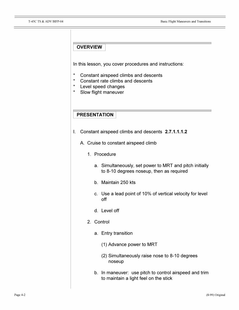
I. Constant airspeed climbs and descents 2.7.1.1.1.2
A. Cruise to constant airspeed climb
1. Procedure
a. Simultaneously, set power to MRT and pitch initiallyto 8-10 degrees noseup, then as required
b. Maintain 250 kts
c. Use a lead point of 10% of vertical velocity for leveloff
d. Level off
2. Control
a. Entry transition
(1) Advance power to MRT
(2) Simultaneously raise nose to 8-10 degreesnoseup
b. In maneuver: use pitch to control airspeed and trimto maintain a light feel on the stick
(8-99) Original
Page 4-3
T-45C TS & ADV BIFP-04 Basic Flight Maneuvers and Transitions
c. Exit transition
(1) Use a lead point of 10% of vertical velocity
(2) Maintain airspeed, monitor altitude readout andvertical velocity for altitude change
(3) Reduce power to cruise setting, adjust pitch forlevel flight, retrim
3. Scan
a. Entry transition
(1) Pitch
(2) RPM/fuel flow indicator
b. In maneuver
(1) Pitch
(2) Airspeed
(3) Altitude
(4) Vertical velocity
c. Exit transition
(1) Pitch
(2) Altitude
(3) Vertical velocity
(4) RPM/fuel flow indicator
(8-99) Original
Page 4-4
Basic Flight Maneuvers and TransitionsT-45C TS & ADV BIFP-04
B. Cruise to constant airspeed descent
1. Procedure
a. Set power to idle
b. Set pitch to 3-6 degrees nosedown
c. Maintain 250 KIAS
d. Use a lead point of 10% of vertical velocity for level-off
2. Control
a. Entry transition
(1) Reduce power to idle
(2) Simultaneously lower nose to 3-6 degreesnosedown
b. In maneuver: use pitch to control airspeed
c. Exit transition
(1) Use a lead point of 10% of vertical velocity
(2) Raise power to cruise setting
(3) Establish pitch reference for level flight and trim
3. Scan
a. Entry transition
(1) Pitch
(2) RPM/fuel flow indicator
b. In maneuver
(1) Pitch
(8-99) Original
Page 4-5
T-45C TS & ADV BIFP-04 Basic Flight Maneuvers and Transitions
(2) Altitude
(3) Vertical velocity
c. Exit transition
(1) Pitch
(2) Altitude
(3) Vertical velocity
(4) RPM/fuel flow indicator
II. Constant rate climbs and descents
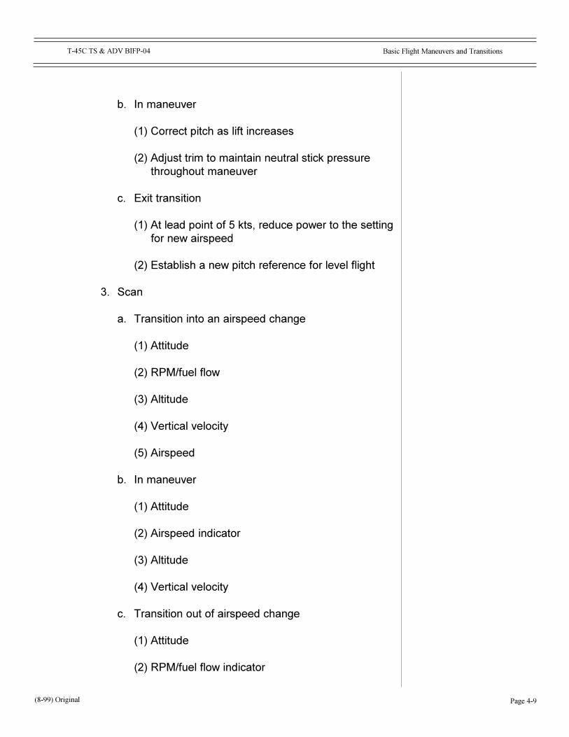
A. Constant rate climb
1. Procedure
a. Set power to 1,500 pph
b. Adjust nose to about 2-3 degrees noseup tomaintain 200 KIAS
c. Adjust power to maintain 1,000 fpm climb
d. Lead level-off at target altitude minus 10% of verticalvelocity
2. Control
a. Entry transition: establish 1,000 fpm rate of climb bysimultaneously advancing power and raising nose
b. In maneuver
(1) Control airspeed with adjustments to pitch
NOTE: Pitot static instruments contain lagfactors. Don't chase the vertical velocity withpitch or power adjustments.
(8-99) Original
Page 4-6
Basic Flight Maneuvers and TransitionsT-45C TS & ADV BIFP-04
(2) Control rate of climb with adjustments to power
c. Exit transition
(1) Use a lead point of 10% of vertical speed
(2) Reduce power to slow cruise setting
(3) Establish a pitch reference for level flight
3. Scan
a. Transition to climb
(1) Pitch
(2) Airspeed
(3) RPM/fuel flow indicator
b. Maintain climb
(1) Pitch
(2) Airspeed
(3) Vertical velocity
(4) RPM/fuel flow indicator
c. Pre-transition for level-off
(1) Altitude
d. Level-off
(1) Pitch
(2) Airspeed
(3) RPM/fuel flow indicator
(8-99) Original
Page 4-7
T-45C TS & ADV BIFP-04 Basic Flight Maneuvers and Transitions
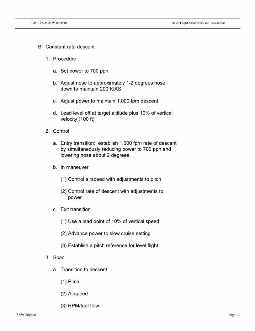
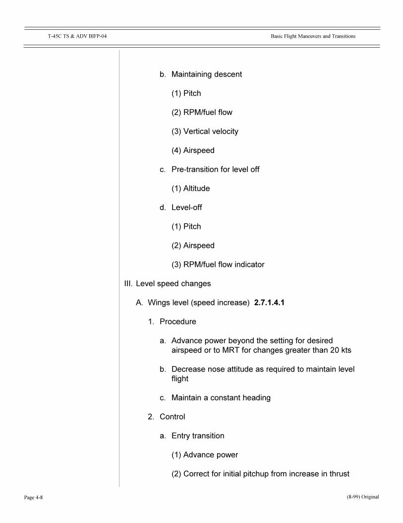
B. Constant rate descent
1. Procedure
a. Set power to 700 pph
b. Adjust nose to approximately 1-2 degrees nosedown to maintain 200 KIAS
c. Adjust power to maintain 1,000 fpm descent
d. Lead level off at target altitude plus 10% of verticalvelocity (100 ft)
2. Control
a. Entry transition: establish 1,000 fpm rate of descentby simultaneously reducing power to 700 pph andlowering nose about 2 degrees
b. In maneuver
(1) Control airspeed with adjustments to pitch
(2) Control rate of descent with adjustments topower
c. Exit transition
(1) Use a lead point of 10% of vertical speed
(2) Advance power to slow cruise setting
(3) Establish a pitch reference for level flight
3. Scan
a. Transition to descent
(1) Pitch
(2) Airspeed
(3) RPM/fuel flow
(8-99) Original
Page 4-8
Basic Flight Maneuvers and TransitionsT-45C TS & ADV BIFP-04
b. Maintaining descent
(1) Pitch
(2) RPM/fuel flow
(3) Vertical velocity
(4) Airspeed
c. Pre-transition for level off
(1) Altitude
d. Level-off
(1) Pitch
(2) Airspeed
(3) RPM/fuel flow indicator
III. Level speed changes
A. Wings level (speed increase) 2.7.1.4.1
1. Procedure
a. Advance power beyond the setting for desiredairspeed or to MRT for changes greater than 20 kts
b. Decrease nose attitude as required to maintain levelflight
c. Maintain a constant heading
2. Control
a. Entry transition
(1) Advance power
(2) Correct for initial pitchup from increase in thrust
(8-99) Original
Page 4-9
T-45C TS & ADV BIFP-04 Basic Flight Maneuvers and Transitions
b. In maneuver
(1) Correct pitch as lift increases
(2) Adjust trim to maintain neutral stick pressurethroughout maneuver
c. Exit transition
(1) At lead point of 5 kts, reduce power to the settingfor new airspeed
(2) Establish a new pitch reference for level flight
3. Scan
a. Transition into an airspeed change
(1) Attitude
(2) RPM/fuel flow
(3) Altitude
(4) Vertical velocity
(5) Airspeed
b. In maneuver
(1) Attitude
(2) Airspeed indicator
(3) Altitude
(4) Vertical velocity
c. Transition out of airspeed change
(1) Attitude
(2) RPM/fuel flow indicator
(8-99) Original
Page 4-10
Basic Flight Maneuvers and TransitionsT-45C TS & ADV BIFP-04
(3) Altitude
(4) Vertical velocity
(5) Airspeed
B. Wings level (speed decrease) 2.7.1.4.1
1. Small change in airspeed
a. Procedure
(1) Decrease power to less than the required settingfor desired airspeed
(2) Increase nose attitude as required to maintainlevel flight
(3) Maintain a constant heading
(4) 5 kts prior to target airspeed, advance power tosetting for new airspeed
(5) Adjust power as required to maintain desiredairspeed
b. Control
(1) Entry transition
(a) Decrease power
(b) Correct for initial pitchdown from decrease inthrust
(2) In maneuver
(a) Correct pitch as lift decreases
(b) Adjust trim to maintain neutral pressurethroughout the maneuver
(8-99) Original
Page 4-11
T-45C TS & ADV BIFP-04 Basic Flight Maneuvers and Transitions
(3) Exit transition
(a) At 5 kts prior to target airspeed, advancepower to the setting for new airspeed
(b) Establish a new pitch reference for level flightand trim
c. Scan
(1) Transition into airspeed change
(a) Attitude
(b) RPM/fuel flow indicator
(c) Altitude
(d) Vertical velocity
(2) In maneuver
(a) Attitude
(b) Altitude
(c) Vertical velocity
(d) Airspeed
(3) Transition out of airspeed change
(a) Attitude
(b) RPM/fuel flow indicator
(c) Altitude
(d) Vertical velocity
(e) Airspeed
(8-99) Original
Page 4-12
Basic Flight Maneuvers and TransitionsT-45C TS & ADV BIFP-04
2. Large or rapid change in airspeed
a. Procedure
(1) Decrease power to the setting for desiredairspeed and extend speed brakes
NOTE: You should anticipate a pitchup withspeed brake extension.
(2) Increase nose attitude as required to maintainlevel flight
(3) Maintain a constant heading
(4) Retract speed brakes 5 kts prior to desiredairspeed
(5) Adjust power to maintain desired airspeed
b. Control
(1) Entry transition
(a) Decrease power
(b) Extend speed brakes
(2) In maneuver
(a) Correct pitch as lift decreases
(b) Adjust trim to maintain neutral pressurethroughout the maneuver
(3) Exit transition
(a) 5 kts prior to desired airspeed, retract speedbrakes
(b) Establish a new pitch reference for level flightand trim
(8-99) Original
Page 4-13
T-45C TS & ADV BIFP-04 Basic Flight Maneuvers and Transitions
c. Scan
(1) Transition into airspeed change
(a) Attitude
(b) RPM/fuel flow indicator
(c) Altitude
(d) Vertical velocity
(2) In maneuver
(a) Attitude
(b) Altitude
(c) Vertical velocity
(d) Airspeed
(3) Transition out of airspeed change
(a) Attitude
(b) RPM/fuel flow indicator
(c) Altitude
(d) Vertical velocity
(e) Airspeed
C. 1/2 SRT (increase airspeed) 2.7.1.10.1
1. Procedure
a. Advance power to above that required for newairspeed
NOTE: Use MRT for speed changes of 20 kts orgreater.
(8-99) Original

Page 4-14
Basic Flight Maneuvers and TransitionsT-45C TS & ADV BIFP-04
b. Establish 1/2 SRT
c. Maintain altitude and constant rate of turn
d. Check heading every 20 seconds for 30 degrees ofchange
e. Reduce power at 5-kt lead point to new airspeedheading
f. Continue constant rate turn to new heading and rollout at a lead of 1/3 AOB
2. Control
a. Entry transition
(1) Increase power to required setting
(2) Establish angle of bank
b. In maneuver
(1) Adjust pitch to maintain altitude
(2) Increase AOB to maintain 1/2 SRT as aircraftaccelerates
(3) Verify turn rate on turn-slip indicator
(4) Trim out stick forces
(5) Make AOB correction if you are ahead or behindturn schedule
c. Exit transition
(1) At lead point of 5 KIAS, decrease power to thesetting for new airspeed
(2) At lead point of 1/3 of AOB, roll out of turn
(3) Establish new pitch reference for level flight
(8-99) Original
Page 4-15
T-45C TS & ADV BIFP-04 Basic Flight Maneuvers and Transitions
3. Scan
a. Transition into the turn
(1) Attitude
(2) Turn-slip
(3) Altitude
(4) Vertical velocity
(5) RPM/fuel flow indicator
b. Maintaining the turn
(1) Attitude
(2) Turn-slip
(3) Altitude
(4) Vertical velocity
(5) Clock
(6) Airspeed
c. Transition out of airspeed change
(1) Attitude
(2) Turn-slip
(3) Altitude
(4) Vertical velocity
(5) Airspeed
(6) RPM/fuel flow indicator
(8-99) Original
Page 4-16
Basic Flight Maneuvers and TransitionsT-45C TS & ADV BIFP-04
d. Roll-out
(1) Attitude
(2) Heading
(3) Altitude
(4) Vertical velocity
(5) Airspeed
(6) RPM/fuel flow indicator
D. 1/2 SRT (decrease airspeed) 2.7.1.10.1
1. Procedure
a. Initiate a 1/2 SRT, 10% of IAS
b. Decrease power to setting for desired airspeed
c. Extend speed brakes
d. Check heading every 20 seconds for 30 degrees ofchange
e. Decrease AOB as airspeed decreases to maintain 1/2 SRT
f. Retract speed brakes at lead point of 5 kts (Trim asrequired to maintain level flight)
g. Continue to new heading and lead roll-out by 1/3AOB
2. Control
a. Entry transition
(1) Decrease power to required setting
(2) Establish angle of bank
(3) Extend speed brakes (8-99) Original

Page 4-17
T-45C TS & ADV BIFP-04 Basic Flight Maneuvers and Transitions
b. In maneuver
(1) Check turn rate using ADI and clock
(2) Verify turn rate on turn needle
(3) Trim to maintain neutral stick pressurethroughout the maneuver
c. Exit transition
(1) At lead point of 5 kts, retract speed brakes andadjust power as necessary
(2) At lead point of 1/3 of AOB, roll out of turn andadjust pitch
(3) Establish new pitch reference for level flight andtrim
3. Scan
a. Transition into the turn
(1) Attitude
(2) Turn-slip
(3) Altitude
(4) Vertical velocity
(5) RPM/fuel flow indicator
b. Maintaining the airspeed change
(1) Attitude
(2) Turn-slip
(3) Altitude
(4) Vertical velocity
(8-99) Original
Page 4-18
Basic Flight Maneuvers and TransitionsT-45C TS & ADV BIFP-04
(5) Clock
(6) Airspeed
c. Transition out of airspeed change
(1) Attitude
(2) Turn-slip
(3) Altitude
(4) Vertical velocity
(5) Airspeed
(6) RPM/fuel flow indicator
d. Roll-out
(1) Attitude
(2) Heading
(3) Altitude
(4) Vertical velocity
(5) Airspeed
(6) RPM/fuel flow indicator
IV. Slow flight maneuver 2.7.1.8.1.1
A. Procedure
1. Level flight
2. Level speed change
3. Perform a 30-degree AOB turn for 90 degrees ofheading change (maintain 200 KIAS)
4. Landing configuration
(8-99) Original
Page 4-19
T-45C TS & ADV BIFP-04 Basic Flight Maneuvers and Transitions
5. 20-degree AOB turn (45 degrees)
6. 20-degree AOB turn (45 degrees)
7. Final approach speed
8. 10-degree AOB turn (30 degrees)
9. 10-degree AOB turn (30 degrees)
10.On-speed descent
11.On-speed level flight
12.Missed approach
13.Slow cruise
14.Level speed change
15.Level flight
B. Control
1. Level speed change
a. Entry
(1) Decrease power and extend speed brakes;adjust pitch after speed brake extension
(2) Increase nose attitude as required to maintainlevel flight
(3) Maintain a constant heading
b. In maneuver: correct pitch for level flight asairspeed decreases
c. Exit
(1) At lead point of 5 kts, retract speed brakes andadjust power to maintain 200 KIAS
(8-99) Original
Page 4-20
Basic Flight Maneuvers and TransitionsT-45C TS & ADV BIFP-04
(2) Establish new pitch reference for level flight
2. 90-degree turn, 30 degrees AOB
a. Entry
(1) Establish 30 degrees angle of bank
(2) Adjust attitude as required to maintain level flightand trim as required
(3) Adjust power to maintain airspeed
b. In maneuver
(1) Maintain 30 degrees angle of bank
(2) Adjust attitude to maintain level flight and trim asrequired
(3) Adjust power as required to maintain airspeed
c. Exit
(1) Use 1/3 of bank angle as lead point for roll-out
(2) Adjust pitch and power during roll-out to maintainlevel flight and airspeed and trim as required
3. Landing approach configuration
a. Entry
(1) Decrease power
(2) Lower gear
(3) Set full flaps/slats
b. In maneuver
(1) Adjust pitch to maintain level flight
(2) Adjust pitch as flaps/slats are extended
(8-99) Original

Page 4-21
T-45C TS & ADV BIFP-04 Basic Flight Maneuvers and Transitions
(3) Trim
c. Exit
(1) At lead point of 5 kts, advance power to maintain150 KIAS
(2) Establish a new pitch reference for level flightand retrim
(3) Complete landing checklist
4. 45-degree turns, 20 degrees AOB
a. Entry
(1) Establish 20 degrees angle of bank
(2) Adjust nose attitude to maintain level flight andtrim as required
(3) Adjust power as required to maintain airspeed
b. In maneuver
(1) Maintain 20 degrees angle of bank
(2) Adjust attitude to maintain level flight and trim asrequired
(3) Adjust power as required to maintain airspeed
c. Exit
(1) Use 1/3 of bank angle as lead point for roll-out
(2) Adjust pitch and power during roll-out to maintainlevel flight and airspeed and trim as required
5. Level speed change to approach speed
a. Entry
(1) Decrease power to 700 pph
(8-99) Original
Page 4-22
Basic Flight Maneuvers and TransitionsT-45C TS & ADV BIFP-04
(8-99) Original
(2) Increase nose attitude as required to maintainlevel flight and trim
(3) Maintain a constant heading
b. In maneuver: correct pitch for level flight asairspeed decreases
c. Exit: adjust nose attitude and power to maintainlevel flight at optimum AOA
6. 30-degree turns, 10 degrees AOB
a. Entry
(1) Establish 10 degrees angle of bank
(2) Adjust attitude to maintain level flight
(3) Adjust power as required to maintain optimumAOA
b. In maneuver
(1) Maintain 10 degrees angle of bank
(2) Adjust attitude to maintain level flight and trim asrequired
(3) Adjust power as required to maintain optimumAOA
c. Exit
(1) Use 1/3 of bank angle as lead point for roll-out
(2) Adjust pitch and power during roll-out to maintainlevel flight and AOA
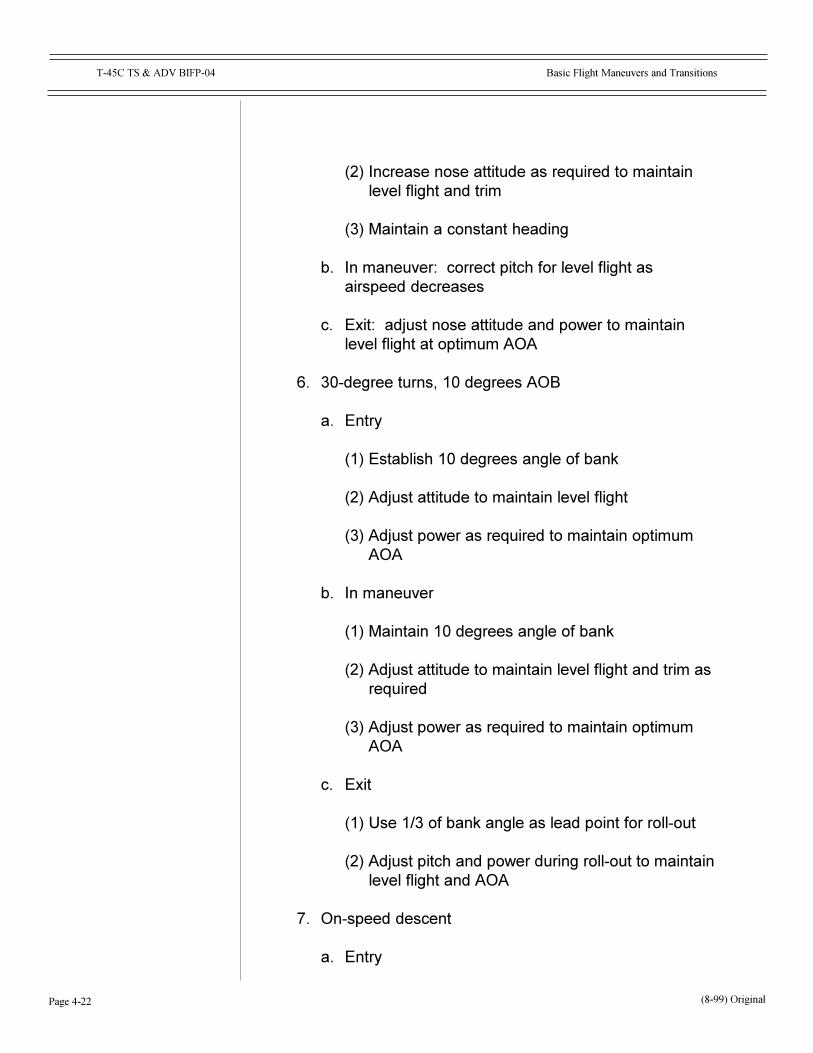
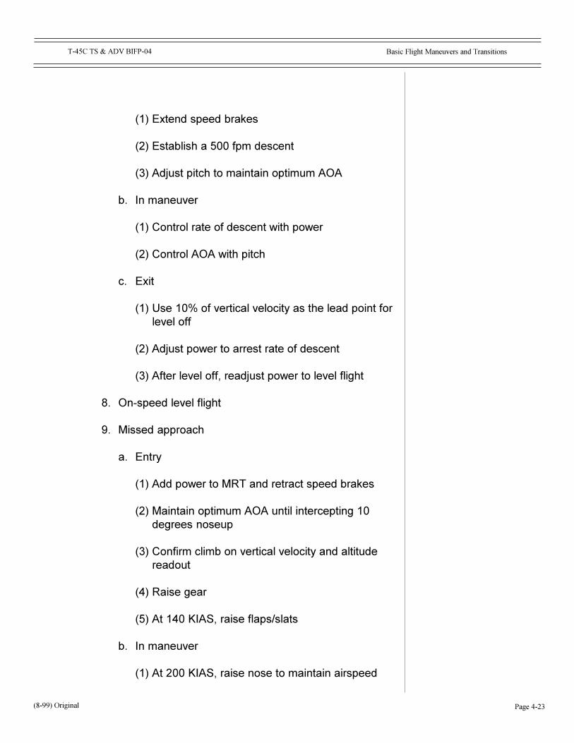
7. On-speed descent
a. Entry
Page 4-23
T-45C TS & ADV BIFP-04 Basic Flight Maneuvers and Transitions
(1) Extend speed brakes
(2) Establish a 500 fpm descent
(3) Adjust pitch to maintain optimum AOA
b. In maneuver
(1) Control rate of descent with power
(2) Control AOA with pitch
c. Exit
(1) Use 10% of vertical velocity as the lead point forlevel off
(2) Adjust power to arrest rate of descent
(3) After level off, readjust power to level flight
8. On-speed level flight
9. Missed approach
a. Entry
(1) Add power to MRT and retract speed brakes
(2) Maintain optimum AOA until intercepting 10degrees noseup
(3) Confirm climb on vertical velocity and altitudereadout
(4) Raise gear
(5) At 140 KIAS, raise flaps/slats
b. In maneuver
(1) At 200 KIAS, raise nose to maintain airspeed
(8-99) Original
Page 4-24
Basic Flight Maneuvers and TransitionsT-45C TS & ADV BIFP-04
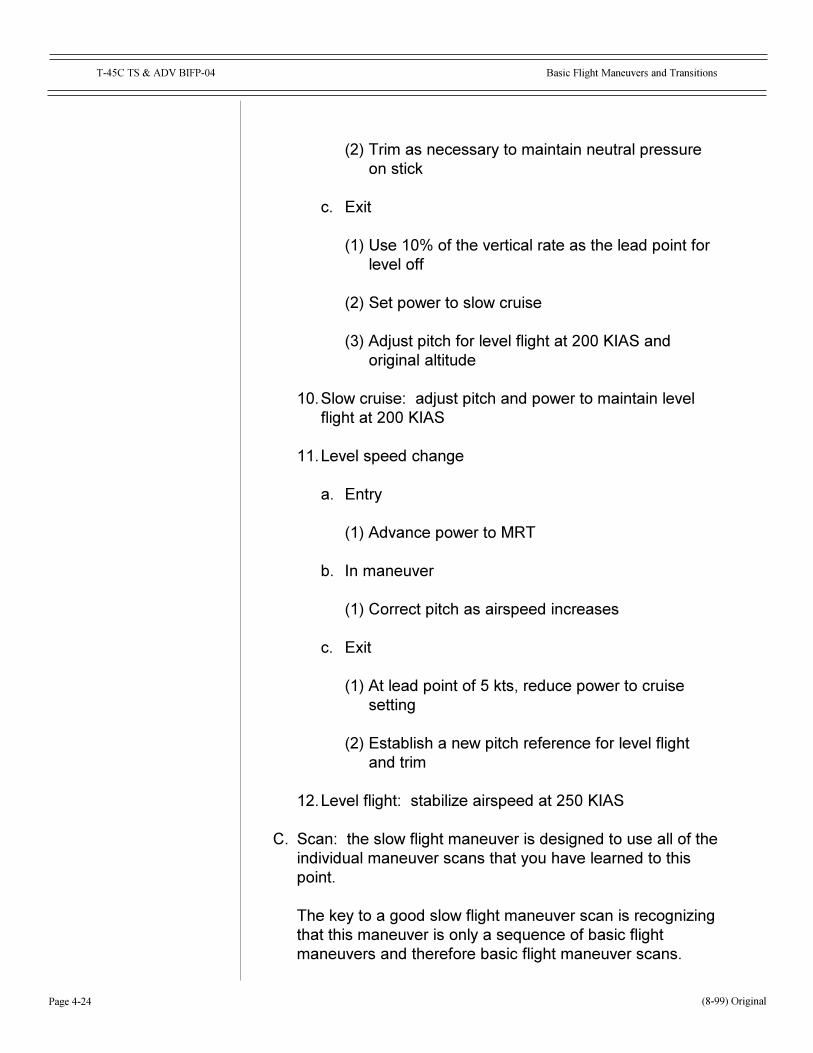
(2) Trim as necessary to maintain neutral pressureon stick
c. Exit
(1) Use 10% of the vertical rate as the lead point forlevel off
(2) Set power to slow cruise
(3) Adjust pitch for level flight at 200 KIAS andoriginal altitude
10.Slow cruise: adjust pitch and power to maintain levelflight at 200 KIAS
11.Level speed change
a. Entry
(1) Advance power to MRT
b. In maneuver
(1) Correct pitch as airspeed increases
c. Exit
(1) At lead point of 5 kts, reduce power to cruisesetting
(2) Establish a new pitch reference for level flightand trim
12.Level flight: stabilize airspeed at 250 KIAS
C. Scan: the slow flight maneuver is designed to use all of theindividual maneuver scans that you have learned to thispoint.
The key to a good slow flight maneuver scan is recognizingthat this maneuver is only a sequence of basic flightmaneuvers and therefore basic flight maneuver scans.
(8-99) Original

Page 4-25
T-45C TS & ADV BIFP-04 Basic Flight Maneuvers and Transitions
CONCLUSION
Basic flight maneuvers and transitions are simply combinations ofthe BI flight building blocks.
You have learned about the procedures, control and scan forthese maneuvers and are ready to progress to more advancedmaneuvers.
(8-99) Original

Page 4-26
Basic Flight Maneuvers and TransitionsT-45C TS & ADV BIFP-04
NOTES
(8-99) Original
�S� PatternsT-45C TS & ADV BIFP-05
Page 5-i
COURSE/STAGE: T-45C TS & ADV Basic Instruments Flight Procedures
LESSON TITLE: �S� Patterns
LESSON IDENTIFIER: T-45C TS & ADV BIFP-05
LEARNING ENVIRONMENT: CAI
ALLOTTED LESSON TIME: 0.8 hr
TRAINING AIDS:
* FiguresFig 1: S-1 PatternFig 2: S-3 Pattern
STUDY RESOURCES: T-45C Instrument FTI
LESSON PREPARATION:
Read:* Sections on �S� patterns in the FTI
REINFORCEMENT: N/A
EXAMINATION:
The objectives in this lesson will be tested in TS & ADV BIFP-10X.
LESSON GUIDE
(8-99) ORIGINAL

�S� PatternsT-45C TS & ADV BIFP-05
Page 5-ii
THIS PAGE INTENTIONALLY LEFT BLANK.

��������
������� �����������������������
���������������
������������������������ ����� ���������������������
������������������������ ����� ���������������������
�������� � ��!
�������"
������� �����������������������
��������
������ �������������� ������������������������������������������������������������������������ ����������� ������ ����������������������������������������������������������������������
������������!���"����������#�$������������%����������������������&������������������������������'������ ����������������� ���������������������� ����������������������������� �����������������������������(���������������������������������� ��������������������������������������������
)��������&�������#�$����������������� ���������������������������
*�������������������#�$������������������������������������������������������������������
��������
+ ��������������!���������&���������������!�������!��������� ����� ������#�$������������'�������&�������������������������������������������������������������������
������������������� �������������!�������!���������� �,
- �����������
- �����������
�������� � ��!

�������#
������� �����������������������
����������
� ������������� ��������
+� *������
�� �������������������������������������������������.�"���&�������
.� /������ ���!000� ������!000� ��
�� �����������������������1���������������������������� ������1����������00� ���������������� �����!000� �������1�������2���������������� ����3
4� (����� ���!000� ������000� ��
5� *�� ������������������������������ �.00�6 +�
7� *���������������������������� ���������������
8� + �����������!������������������� �����!��������9���������� �������������������������������������
:� (����
�� %�����������������
�� %����������������������������2������������."���&�������3
�� %����������������������� ���.�������������
�� %���������������������� �800����
�����������������
�������� � ��!
��������
������� �����������������������
�������� � ��!
�������������� �����
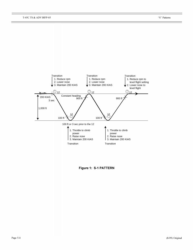
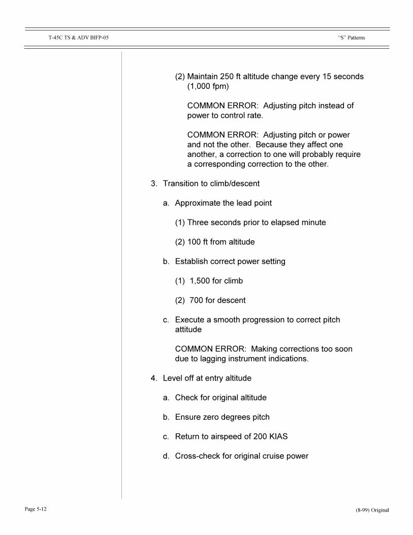
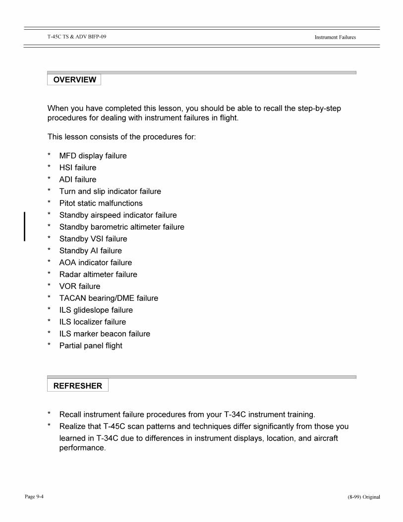
Transition Transition
100 ft
12
12
Transition
Constant heading
1. Reduce rpm2. Lower nose3. Maintain 200 KIAS
1. Reduce rpm2. Lower nose3. Maintain 200 KIAS
Transition Transition
900 ft200 KIAS3 sec
1,000 ft
1212
1. Throttle to climb power2. Raise nose3. Maintain 200 KIAS
1. Throttle to climb power2. Raise nose3. Maintain 200 KIAS
1. Reduce rpm to level flight setting2. Lower nose to level flight
900 ft
100 ft
100 ft or 3 sec prior to the 12
12

��������
������� �����������������������
.� (��������������
�� +������
2�3 ;�����������.00�6 +�
2.3 %�����������������
2�3 ��.�������������� ��������
2�3 .���������������� �������
(<;;<=�%��<�,��+>������������������ �����������������������
�� ����
2�3 ;�����������������������
2�3 ��!500����� �������
2�3 �800����� ��������
2.3 ;��������.50� ������������������������5������2�!000� ��3
(<;;<=�%��<�,��+>�������������������� ������������������ �������������������
(<;;<=�%��<�,��+>������������������������������������:������������� ������������!��������������������������������?�������������������������������������
�� �����������������1������
�� +����������������������
2�3 ��������������������������������
2.3 �00� �� ����������
�������� � ��!

�������$
������� �����������������������
�� %����������������������������
2�3 �+�������������!500����� �������
2.3 �+������������800����� ��������
�� %���������������������������������������������
(<;;<=�%��<�,��;�&����������������������������������@� �����������������������2��������������3�
4� A����� �����������������
�� +>���������������������������������� ��!�00����
�� ;���������������� �.00�6 +�
�� (���&� �����������������
(� ����
�� �����������������
�� +������,��+/
�� *���,��B���� ����������
�� *�� ������
2�3 +������
2.3 +������
2�3 @���������������
243 C�����
.� ��������������������
�� +������,��+/
�� *���,��B���� ����������
�������� � ��!

�������%
������� �����������������������
�� *�� ������
2�3 (��&
2.3 +������
2�3 @���������������
243 +������
253 C�����
�� ;�����������������
�� +������,��+/
�� *�� ������
2�3 +������
2.3 @���������������
2�3 +������
243 C�����
253 (��&
4� *������������
�� +������,��+/
�� *���,��B���� ����������
�� *�� ������
2�3 +������
2.3 @���������������
2�3 +������
243 C�����
253 (��&�������� � ��!
��������
������� �����������������������
5� �����������������
�� +������,��+/
�� *���,��B���� ����������
�� *�� ������
2�3 +������
2.3 @���������������
2�3 +������
243 C�����
253 (��&
7� ;����������������
�� +������,��+/
�� *�� ������
2�3 +������
2.3 @���������������
2�3 +������
243 C�����
253 (��&
8� *������������� ��������
�� +������,��+/
�� *���,��B���� ����������
�������� � ��!
�����������������
��������
������� �����������������������
�������� � ��!
�������������� �����
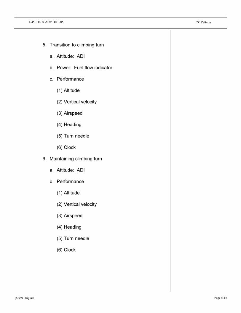
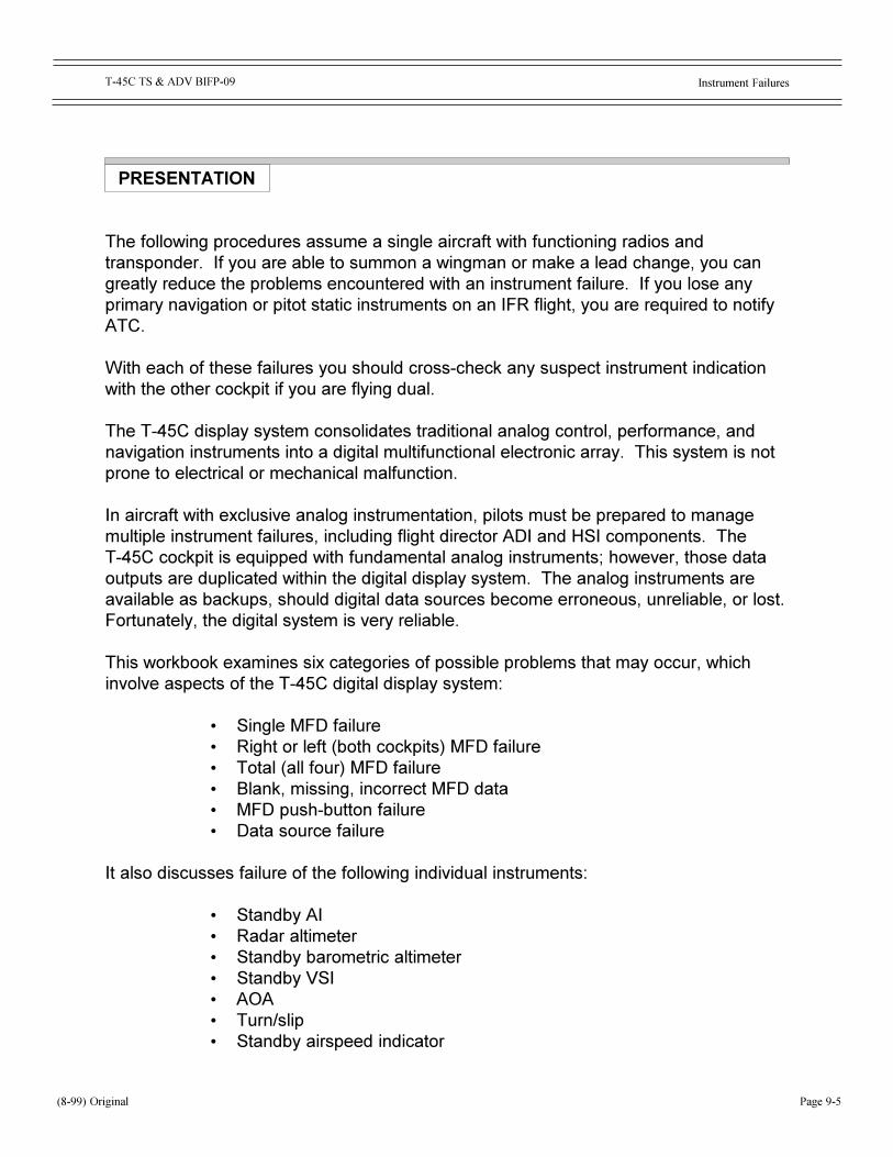
200 KIASTrimmed
1,000 ft1 min
150
180
120
Aircraft heading 090
210240270240
090
120
090
150
180
���������
������� �����������������������
�� *�� ������
2�3 +������
2.3 @���������������
2�3 +������
243 C�����
253 (��&
D� A�����
�� +������,��+/
�� *���,��B���� ����������
�� *�� ������
2�3 +������
2.3 +������
2�3 @���������������
243 C�����
� ������������� ��������
+� *������
�� �������������������������
�� ���������������������������������������������.�"���&�������
�� /������ ���!000� ������!000� ����������������� ��!000� ������!000� ��
�� ���������������� �������������������������������������������2�����3����00� ���������������� �����!000� ���������2�����3�2���������������� ����3
�������� � ��!

���������
������� �����������������������
� *�� ������������������������������ �.00�6 +�
.� :��������������1.��������������������������������� � �����������
�� ���������������� ������������������� �������������
4� *������������������������ �����������
:� (����
�� %�����������������
�� %����������������������������2��������.�"���&������3
�� %���������������������� �800����
�� %����������������������������.�������������
.� (��������������
�� +������
2�3 ;�����������.00�6 +�
2.3 %�����������������
2�3 .���������������� �������
2�3 ��.�������������� ��������
(<;;<=�%��<�,��+>������������������ �����������������������
�� ����
2�3 ;�����������������������
2�3 �!500����� �������
2�3 800����� ��������
�������� � ��!
��������"
������� �����������������������
2.3 ;��������.50� ������������������������5������2�!000� ��3
(<;;<=�%��<�,��+>�������������������� ������������������
(<;;<=�%��<�,��+>������������������������������������:������������� ������������!��������������������������������?�������������������������������������
�� �����������������1������
�� +����������������������
2�3 ��������������������������������
2.3 �00� �� ����������
�� %����������������������������
2�3 ��!500� �������
2.3 �800� ��������
�� %���������������������������������������������
(<;;<=�%��<�,��;�&����������������������������������������������������
4� A����� �����������������
�� (���&� �����������������
�� %������9���������������
�� ����������������� �.00�6 +�
� (��������&� ���������������������
�������� � ��!

��������#
������� �����������������������
5� �����
�� %������������&��������������������������������� ������
�� +>����������������������������������� �.006 +�
�� +>��������������������������������!000� ������� ������1������
� C����������������������0��������������.0�����
(� ����
�� �����������������
�� +������,��+/
�� *�� ������
2�3 +������
2.3 +������
2�3 @���������������
243 C�����
.� ���������������������������
�� +������,��+/
�� *���,��B���� ����������
�� *�� ������
2�3 +������
2.3 @���������������
2�3 +������
243 C�����
�������� � ��!
���������
������� �����������������������
�������� � ��!
253 ����������
273 (��&
�� ;������������������������
�� +������,��+/
�� *�� ������
2�3 +������
2.3 @���������������
2�3 +������
243 C�����
253 ����������
273 (��&
4� *������������
�� +������,��+/
�� *���,��B���� ����������
�� *�� ������
2�3 +������
2.3 @���������������
2�3 +������
243 C�����
253 ����������
273 (��&
���������
������� �����������������������
�������� � ��!
5� �������������������������
�� +������,��+/
�� *���,��B���� ����������
�� *�� ������
2�3 +������
2.3 @���������������
2�3 +������
243 C�����
253 ����������
273 (��&
7� ;������������������������
�� +������,��+/
�� *�� ������
2�3 +������
2.3 @���������������
2�3 +������
243 C�����
253 ����������
273 (��&

��������$
������� �����������������������
�������� � ��!
8� *������������� ��������
�� +������,��+/
�� *���,�� ���� ����������
�� *�� ������
2�3 +������
2.3 @���������������
2�3 +������
243 C�����
253 ����������
273 (��&
D� A�����
�� +������,��+/
�� *���,��B���� ����������
�� *�� ������
2�3 +������
2.3 @���������������
2�3 +������
243 C�����
��������%
������� �����������������������
�������
����������������������������!������!���������������?��� �,
- �����������
- �����������
��������
+����=�����������!�������������>������������������"���������������� �������������������������������������������?�������������������������� ����������������� ����������������������� ������������������� ������������������������ ������������������������������������������������&��������������������������
�������� � ��!

���������
������� �����������������������
����
�������� � ��!

Instrument FailuresT-45C TS & ADV BIFP-09
Page 9-i
WORKBOOK LESSON
COURSE/STAGE: T-45C TS & ADV Basic Instruments Flight Procedures
LESSON TITLE: Instrument Failures
LESSON IDENTIFIER: T-45C TS & ADV BIFP-09
TRAINING AIDS:
* FiguresFig 1: Failed AIFig 2: Failed AOA
STUDY RESOURCES:
* NATOPS Instrument Flight Manual, NAVAIR 00-80T-112* T-45C NATOPS Flight Manual, A1-T45AC-NFM-000
LESSON PREPARATION:
Read:* Paragraphs 17.6.1 and 17.6.2 in the NATOPS Instrument Flight Manual,
NAVAIR 00-80T-112
REINFORCEMENT:
Review:* Your Eng-21 Lesson Guide, �Flight Instrument Malfunctions�
EXAMINATION:
The objectives in this lesson will be tested in TS BIFP-10X andADV BIFP-07X.
(8-99) ORIGINAL

Instrument FailuresT-45C TS & ADV BIFP-09
Page 9-ii
THIS PAGE INTENTIONALLY LEFT BLANK.
Instrument Failures
Page 9-1
T-45C TS & ADV BIFP-09
LESSON OBJECTIVES
2.8.1.1.1Recall procedure for GINA failure
1.8.1.7.12.2Recall procedure for HSI failure
1.8.1.7.1.2Recall procedure for ADI failure
1.8.1.7.10.2Recall procedure for turn and slip indicator failure
1.8.1.7.3.2Recall procedure for pitot static malfunctions
1.8.1.7.2.2Recall procedure for airspeed indicator failure
1.8.1.7.9.2Recall procedure for altimeter failure
1.8.1.7.8.2Recall procedure for VSI failure
1.8.1.7.6.2Recall procedure for standby attitude indicator (AI) failure
1.8.1.7.4.2Recall procedure for AOA indicator failure
1.8.1.7.11.2Recall procedure for radar altimeter failure
1.8.1.9.8.2Recall procedure for VOR failure
1.8.1.9.4.2Recall procedure for TACAN bearing failure
(8-99) Original

Page 9-2
Instrument FailuresT-45C TS & ADV BIFP-09
1.8.1.9.9.2Recall procedure for ILS glideslope failure
1.8.1.9.10.2Recall procedure for ILS localizer failure
1.8.1.9.11.2Recall procedure for ILS marker beacon failure
2.7.4.1.1Recall procedures for flight with partial panel
(8-99) Original

Instrument Failures
Page 9-3
T-45C TS & ADV BIFP-09
HOW TO USE THIS WORKBOOK
1. This is a workbook/lab that you will complete in group session with an instructor.FLIP publications, charts, and the T45C NATOPS will be available.
2. Lesson information is accompanied by exercises and/or questions to measure yourunderstanding of the subject matter. Answers are provided in the back of theworkbook to allow you to monitor your progress through the lesson.
MOTIVATION
Aircraft instrument systems are subjected to an exceptionally harsh environment of gloading and extremes of temperature, pressure, and humidity. It is a tribute to theefforts of manufacturers and maintenance personnel that we so rarely experience aninstrument failure in flight. Although rare, instrument failures do happen, so it is crucialthat you be prepared to handle one safely.
(8-99) Original
Page 9-4
Instrument FailuresT-45C TS & ADV BIFP-09
OVERVIEW
When you have completed this lesson, you should be able to recall the step-by-stepprocedures for dealing with instrument failures in flight.
This lesson consists of the procedures for:
* MFD display failure
* HSI failure
* ADI failure
* Turn and slip indicator failure
* Pitot static malfunctions
* Standby airspeed indicator failure
* Standby barometric altimeter failure
* Standby VSI failure
* Standby AI failure
* AOA indicator failure
* Radar altimeter failure
* VOR failure
* TACAN bearing/DME failure
* ILS glideslope failure
* ILS localizer failure
* ILS marker beacon failure
* Partial panel flight
REFRESHER
* Recall instrument failure procedures from your T-34C instrument training.
* Realize that T-45C scan patterns and techniques differ significantly from those you
learned in T-34C due to differences in instrument displays, location, and aircraftperformance.
(8-99) Original
Instrument Failures
Page 9-5
T-45C TS & ADV BIFP-09
PRESENTATION
The following procedures assume a single aircraft with functioning radios andtransponder. If you are able to summon a wingman or make a lead change, you cangreatly reduce the problems encountered with an instrument failure. If you lose anyprimary navigation or pitot static instruments on an IFR flight, you are required to notifyATC.
With each of these failures you should cross-check any suspect instrument indicationwith the other cockpit if you are flying dual.
The T-45C display system consolidates traditional analog control, performance, andnavigation instruments into a digital multifunctional electronic array. This system is notprone to electrical or mechanical malfunction.
In aircraft with exclusive analog instrumentation, pilots must be prepared to managemultiple instrument failures, including flight director ADI and HSI components. TheT-45C cockpit is equipped with fundamental analog instruments; however, those dataoutputs are duplicated within the digital display system. The analog instruments areavailable as backups, should digital data sources become erroneous, unreliable, or lost.Fortunately, the digital system is very reliable.
This workbook examines six categories of possible problems that may occur, whichinvolve aspects of the T-45C digital display system:
� Single MFD failure� Right or left (both cockpits) MFD failure� Total (all four) MFD failure� Blank, missing, incorrect MFD data� MFD push-button failure� Data source failure
It also discusses failure of the following individual instruments:
� Standby AI� Radar altimeter� Standby barometric altimeter� Standby VSI� AOA� Turn/slip� Standby airspeed indicator
(8-99) Original

Page 9-6
Instrument FailuresT-45C TS & ADV BIFP-09
And, it addresses failure of the following navigation equipment:
� VOR� TACAN� ILS glideslope� ILS localizer� Marker beacon
Finally, partial panel instrument flight is discussed.
(8-99) Original

Instrument Failures
Page 9-7
T-45C TS & ADV BIFP-09
MFD DISPLAY FAILURE 2.8.1.1.1
When a T-45C pilot first sees or suspects an MFD display problem, he shouldcoordinate with the other pilot to determine if both cockpit display systems are involved.Next, the problem MFD(s) should be recycled to OFF and then back to N or D, asappropriate.
Single MFD Failure: If just a single MFD display unit appears inoperative and thescreen is blank, the pilot should turn the MFD CONT and BRT knobs full clockwise. If,then, a raster scan is visible, it can be concluded that the unit is electronically functional.If no raster scan becomes visible, cycle the DISPLAY POWER switch to RESET, whichwill recycle power to the DEU. If after recycling, a raster scan is still not visible,conclude that the MFD display unit is probably nonrecoverable. The problem is with aninternal MFD component, with wiring, or elsewhere in the display system. With just onegood MFD, the pilot will have to individually select single page displays that are mostappropriate to the concern of the moment: stores management, system analysis,cruise, approach, recovery, etc.
Right or Left (both cockpits) MFD Failure: When right or left MFDs in both cockpitsappear to have failed, it is likely that a left or right raster graphic generator is the cause.The displays may exhibit a complete or partial data loss, or the freezing of datadisplays. To possibly correct the problem, cycle the DISPLAY POWER switch toRESET. If that does not correct the problem, conclude that both display units arenonrecoverable.
Total (all four) MFD Failure: Total failure of all four MFDs is unlikely. Such an unusualcircumstance would most likely relate to a malfunction within the DEU. About all a pilotcan do is cycle the DISPLAY POWER switch to RESET, recycling power to the DEU. Ifthat fails to correct the problem, the MFDs are probably nonrecoverable. Aircraftrecovery will have to be accomplished using standby instruments. Navigation sourceswill not be available, so assistance should be sought from ATC and/or other aircraft, asappropriate. Consider declaring an in-flight emergency.
Blank, Missing, Incorrect MFD data: Missing data on an MFD might be the result of avariety of problems. Whether or not an AV BIT legend appears in the lower right-handcorner of the MFD(s), select the BIT page option and check for GO, OPGO, and DEGDalerts. Reset or recycle equipment, as may be appropriate. If the MFD system wasmissing attitude and/or position information, the problem may be related to a GINAfailure; then, expect the GINA BIT to indicate DEGD. TACAN, airspeed, and altimeterinformation will still be displayed, concurrently with a GINA failure.
(8-99) Original
Page 9-8
Instrument FailuresT-45C TS & ADV BIFP-09
MFD Push-Button Failure: An apparent MFD problem may be caused by amalfunctioning MFD push-button. If that happens while on the ground, initiate DSPYMBIT (manual BIT) checking of the MFD push-buttons; DEP push-buttons can also bechecked. When in-flight, DSPY MBIT is disabled. Push-button functionality can only beassessed by manipulating the individual push-buttons.
Data Source Failure: Some systems�such as TACAN, VOR, and ILS�are notautomatically BIT monitored and reported on the BIT status display page. If data froman unmonitored source appears missing or incorrect, first, check the status of thatequipment. Be certain that it is properly turned ON and that it is properly set for desiredoperation. Then, if the equipment incorporates a stand-alone BIT feature, activate thatBIT to check functionality.
HSI FAILURE 1.8.1.7.12.2
A digital display system does not manifest a failed HSI in the same context as a flightdirector or older analog system. The HSI display page can be called up in a variety offormats and on multiple MFD units.
The HSI display page presents a lot of data; some graphically and somealphanumerically. Different MFD/DEU system problems will result in different visiblecircumstances. For example, loss of the GINA will cause a loss of aircraft attitude andINS-based position information, but TACAN, airspeed, and altitude will remain.Additionally, a stuck MFD push-button may disable a particular HSI function on thatparticular MFD unit. Switching the display to another unit may resolve the difficulty.
As you know, there are no warning or OFF flags on the HSI display, other than AV BIT.If a data or graphical image problem is suspected, four logical investigative steps shouldbe followed:
� Be sure associated equipment that supplies the data in question is ON.� Be sure data has been properly entered: e.g., waypoint data, frequencies.� Perform BIT checks on suspect equipment: e.g., TACAN, VOR/ILS.� Check the DATA display page for any OPGO/DEGD alerts and react
accordingly.
Normally, the HSI will be selected for display on the right MFD. To assure that an HSIproblem is not really an MFD problem, call up the same HSI display on another MFDunit and compare results.
(8-99) Original
Instrument Failures
Page 9-9
T-45C TS & ADV BIFP-09
The procedure for dealing with an HSI failure is:
1. Determine the nature of the malfunction.2. Use backup navigation instruments as appropriate.3. Report essential HSI failure to ATC.4. Maintain VFR conditions, if possible5. Land as soon as practicable.
ADI FAILURE 1.8.1.7.1.2
A digital display system does not manifest a failed ADI in the same context as a flightdirector or older analog system. The ADI display page can be called up on multipleMFD units in the two cockpits.
The ADI display page presents not only aircraft attitude data, but also heading, BAROaltitude, radar altitude, KIAS, TAS, AOA, Mach, g-loadings, vertical velocity, and turn/slip information. Additionally, LAW and BINGO parameters can be set using thisdisplay page and associated increment/decrement push-buttons.
Loss of the GINA will cause a loss of the aircraft attitude portion of the ADI display.Loss of other instruments (e.g., radar altimeter) will result in the loss of associatedreadouts on the ADI. Additionally, a stuck MFD push-button may just disable aparticular ADI function on that particular MFD unit. Switching the desired display toanother unit may resolve the difficulty.
As you know, there are no warning or OFF flags on the ADI display, other than AV BIT.If a data or graphical image problem is suspected, four logical investigative steps shouldbe followed:
� Be sure associated equipment that supplies the data in question is ON.� Be sure data has been properly entered: e.g., the proper ILS frequency is
needed for ILS steering, CDI mode is needed for both VOR and ILS.� Perform BIT checks on suspect equipment: e.g., radar altimeter, VOR/ILS.� Check the DATA display page for any OPGO/DEGD alerts and react
accordingly.
Normally, the ADI will be selected for display on the left MFD. To assure that an ADIproblem is not really an MFD problem, call up the ADI display on another MFD unit andcompare results.
(8-99) Original
Page 9-10
Instrument FailuresT-45C TS & ADV BIFP-09
The procedure for dealing with an ADI failure is:
1. Use the standby attitude indicator (AI) for attitude reference.2. If available, use the HSI for your primary heading reference; if not, use the standby
compass.3. Maintain VFR and VMC conditions, if possible.4. Report essential ADI instrument failure to ATC.5. Be alert for any progressive failure of attitude and navigation information sources.6. Land as soon as practicable.
TURN AND SLIP INDICATOR FAILURE 1.8.1.7.10.2
A turn and slip indicator is part of the ADI display page. It is backed up by a stand-alone (the standby) turn and slip indicator located on the left side of the main instrumentpanel. In the rare event that both turn needle indicators fail, the pilot will have to useairspeed and bank angle to perform standard and 1/2 standard rate turns.
A total loss of the ADI display page, including the electronically displayed turn and slipindicator, is unlikely, unless associated with physical damage, a DEU failure, or anelectrical power problem. An additional failure of the stand-alone turn and slip indicatoris even more unlikely.
If a malfunction of the MFD turn and slip indicator is suspected:
� Check the indicator against the standby turn and slip indicator.� Check the indicator against the ADI and standby AI bank indications.� Check the indicator against rudder pedal position, and against the rudder trim
position indicator.� Check the indicator against any physical sensation of a slip.� Check the DATA display page for any related OPGO/DEGD alerts.
If the ADI turn and slip indicator is inaccessible, or its indications are incorrect, modifyyour cross-check to include the standby turn and slip indicator.
There is no specific procedure for dealing with a simultaneous malfunction of both slipindicators, because that circumstance is very unlikely. Also, the impact of losing bothsideslip indicators is not critical enough to warrant a prescribed remedial action.
The procedure for dealing with a failure of both turn and slip indicators is:
1. Check the ADI(s) to validate correct indications.2. Be alert to possible electrical problems.3. Use the ADI or standby AI (whichever is available) and airspeed indicator for
controlling turn rate.(8-99) Original
Instrument Failures
Page 9-11
T-45C TS & ADV BIFP-09
PROGRESS CHECK
Question 1 � 2.8.1.1.1If the GINA fails, which of the following is true?
a) GINA OFF-flag appears on the ADI display page.b) AV BIT alert box appears on the ADI display page.c) AV BIT alert box appears on all MFD display pages.d) Position and airspeed data are lost.
ANSWER:
Question 2 � 1.8.1.7.12.2In the event of an HSI position information failure and an associated AV BITalert, what is a likely cause?
ANSWER:
Question 3 � 1.8.1.7.1.2What is the most vital step in the ADI failure procedure?
a) Use the standby attitude indicator and maintain aircraft control.b) Reset the ADI erect switch.c) Watch for possible progressive failure.d) Check the electrical system.
ANSWER:
Question 4 � 1.8.1.7.10.2Which of the following steps apply when the turn and slip indicator fails?
a) Use the ADI bank indices for rudder trim reference.b) Use the ADI and airspeed for turn rate reference.c) Check the ADI for correct indications.d) Be aware of possible electrical problems.
ANSWER:
(8-99) Original

Page 9-12
Instrument FailuresT-45C TS & ADV BIFP-09
PITOT STATIC MALFUNCTIONS 1.8.1.7.3.2
If the entire pitot static system fails, you will lose all airspeed, all barometric altitude, andall vertical velocity indicators in both cockpits. Verify the failure of any pitot staticinstrument by cross-checking indications between standby and MFD readouts, and withthe other cockpit. A failure may result in frozen readouts, or zero readouts.
You can compensate for a total loss of the airspeed indications by flying the equivalentangle of attack for climb, cruise, descent, and landing. See the Performance Datasection of NATOPS.
You have two ways to make up for the loss of barometric altitude information. First, youcan use the radar altimeter for height above ground up to 5,000 ft AGL. Second, youcan use the cabin pressure altimeter for altitude information. (Note: Regulationsprohibit flight above 25,000 ft MSL if the cockpit has been depressurized). The cabinpressure altimeter does not compensate for local barometric pressure and should onlybe considered accurate to +/- 500 ft.
To compensate for a total loss of vertical velocity information, use the clock to time theamount of altitude change occurring over a specific period of time. For example, if youdescend 200 ft in 15 seconds, your rate of descent is 800 ft per minute.
The procedure for dealing with a total pitot static system failure is:
1. Check PITOT HEAT -- ON.2. Compare instruments in both cockpits. Use AOA, radar altimeter, and/or cabin
pressure altimeter to calculate the approximate airspeed and altitude.3. Report the failure to ATC.4. Maneuver to exit icing conditions (if applicable).5. Remain VMC, if possible.6. Join with wingman if possible.7. Consider declaring an in-flight emergency.
STANDBY AIRSPEED INDICATOR FAILURE 1.8.1.7.2.2
A standby airspeed indicator failure��by itself��is not a problem, providing airspeedinformation on the display system is still available and correct. If, however, bothindication systems fail (or are in error), you may have to fly AOA in lieu of indicatedairspeed for basic aircraft control. An extensive list of equivalent AOAs for the T-45Care listed in the Emergency Procedures section of NATOPS (main manual and pilot'spocket checklist). Some examples follow:
(8-99) Original

Instrument Failures
Page 9-13
T-45C TS & ADV BIFP-09
Takeoff 20 units (full flaps)Climb 10-11 unitsMaximum range 12-13 unitsApproach 17 units
The procedure for dealing with a combined standby airspeed indicator failure, plus adisplay system airspeed failure is:
1. Check PITOT HEAT -- ON.2. Report the failure to ATC.3. Fly AOA in place of airspeed.4. Be aware that display system navigation information that uses airspeed may be
missing or incorrect.5. Watch for other indications of pitot static system problems.6. Land as soon as practicable.
STANDBY BAROMETRIC ALTIMETER FAILURE 1.8.1.7.9.2
You have two options to make up for the loss of the standby barometric altimeter. Thesystem may or may not show proper altitude on display system altitude readouts.
First, you can use the radar altimeter for height above ground for altitudes up to 5,000 ftAGL. You must add ground elevation to radar altitude to approximate mean sea level(MSL) altitudes.
Second, you can obtain backup altitude information from the cabin pressure altimeter.This instrument should be considered accurate to +/-500 ft and is primarily useful ataltitudes above 5,000 ft AGL, peak altitude for the radar altimeter. In order to use thecabin pressure altimeter above 5,000 ft MSL, you will have to depressurize the cockpit,and depressurized flight above 25,000 ft is prohibited.
Don�t forget to cross-check your other pitot static system instruments (airspeed andvertical velocity indicator) to determine if they are operating correctly. The verticalvelocity indication on the ADI display is generated by the GINA and is not affected by apitot static system malfunction.
The procedure for dealing with a standby barometric altimeter failure that also includesdisplay system barometric altitude readout failure is:
1. Check PITOT HEAT -- ON.2. Report altimeter failure to ATC.3. Use the radar and the cabin pressure altimeters to determine altitude (depressurize
cockpit if required).
(8-99) Original
Page 9-14
Instrument FailuresT-45C TS & ADV BIFP-09
4. Be aware that the IFF altitude encoding signals may also be in error.5. Land as soon as practicable.
STANDBY VSI FAILURE 1.8.1.7.8.2
If you lose all vertical velocity information (standby and display systems), use the clockto gauge the amount of altitude change occurring over a specific period of time. Forexample, if you descend 200 ft in 15 seconds, your rate of descent is 800 ft per minute.You can also use this procedure to check the accuracy of a suspect VSI.
It is important that you determine whether other instruments in the pitot static systemare operating correctly. What may appear to be a stuck or erroneously indicating VSIcould be part of a larger pitot static system problem.
NOTE: With a failed VSI and display system vertical velocity readout, your PARapproach capability is severely limited.
The procedure for dealing with a total VSI/vertical velocity readout failure is:
1. Check that PITOT HEAT -- ON.2. Cross-check the altimeter and clock for a vertical velocity reference.3. Check functionality of HUD velocity vector and use as appropriate aid.4. Watch for other indications of possible pitot static problems.
PROGRESS CHECK
Question 5 � 1.8.1.7.3.2Which of the following instruments may be affected by a pitot staticmalfunction?
a) Airspeed indicatorb) Barometric altimeterc) Vertical velocityd) Standby vertical speed indicatore) Angle of attack indicator
ANSWER:
(8-99) Original
Instrument Failures
Page 9-15
T-45C TS & ADV BIFP-09
PROGRESS CHECK
Question 6 � 1.8.1.7.2.2With failure of the airspeed indicator, fly ___________ AOA to attain maximumrange cruise.
a) 17b) 14c) 12-13d) 10-11
ANSWER:
Question 7 � 1.8.1.7.9.2When experiencing a suspected altimeter failure, which of the following areimportant considerations?
a) You must add ground elevation to radar altitude to approximate MSLaltitudes.b) Depressurize the cockpit when using the cabin pressure altimeter.c) Use the radar altimeters up to 5,000 ft AGL.d) Recognize the possibility of an IFF altimeter error problem.
ANSWER:
Question 8 � 1.8.1.7.8.2With a failed VSI, you may cross-check the clock and altimeter to gauge verticalvelocity. A 600 fpm vertical velocity is equivalent to:
a) 200 ft change in 15 secondsb) 300 ft change in 20 secondsc) 200 ft change in 20 secondsd) 150 ft change in 20 seconds
ANSWER:
(8-99) Original
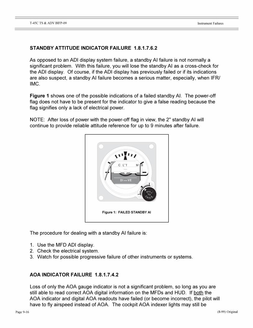
Page 9-16
Instrument FailuresT-45C TS & ADV BIFP-09
STANDBY ATTITUDE INDICATOR FAILURE 1.8.1.7.6.2
As opposed to an ADI display system failure, a standby AI failure is not normally asignificant problem. With this failure, you will lose the standby AI as a cross-check forthe ADI display. Of course, if the ADI display has previously failed or if its indicationsare also suspect, a standby AI failure becomes a serious matter, especially, when IFR/IMC.
Figure 1 shows one of the possible indications of a failed standby AI. The power-offflag does not have to be present for the indicator to give a false reading because theflag signifies only a lack of electrical power.
NOTE: After loss of power with the power-off flag in view, the 2" standby AI willcontinue to provide reliable attitude reference for up to 9 minutes after failure.
The procedure for dealing with a standby AI failure is:
1. Use the MFD ADI display.2. Check the electrical system.3. Watch for possible progressive failure of other instruments or systems.
AOA INDICATOR FAILURE 1.8.1.7.4.2
Loss of only the AOA gauge indicator is not a significant problem, so long as you arestill able to read correct AOA digital information on the MFDs and HUD. If both theAOA indicator and digital AOA readouts have failed (or become incorrect), the pilot willhave to fly airspeed instead of AOA. The cockpit AOA indexer lights may still be
(8-99) Original
Figure 1: FAILED STANDBY AI
GA
C L I M BO F F
U L
C E
LP

Instrument Failures
Page 9-17
T-45C TS & ADV BIFP-09
available. Be aware that in some AOA failure situations, the AOA approach lights willalso become either inoperative or signal incorrect readings to the ground observer/LSO.
Figure 2 shows one possible indication of a failed AOA indicator: an OFF flag. TheOFF flag does not have to be present for the indicator to give false readings because itindicates only a lack of electrical power.
The procedure for dealing with a total AOA readout failure is:
1. Use the airspeed indicator.2. Fly calculated approach speeds, using the airspeed indicator.3. Inform Tower/Approach/LSO (as appropriate) in case the aircraft's AOA approach
lights have been affected.
RADAR ALTIMETER FAILURE 1.8.1.7.11.2
With a failed radar altimeter, you lose your height-above-ground reference. The onlycockpit radar altimeter readouts are in a digital format on the HUD and MFD displays. Ifyou are aware of your location and the local terrain, the danger is minimal. If you haveany doubt about your position or the topography of the surrounding area, you shouldnotify the controlling agency and immediately climb to a safe altitude. This isparticularly true at night and during IMC.
Once you are sure of the local surface elevation and have confirmed that the barometricaltimeter has the correct setting, you should be able to use it for all altitude references.
(8-99) Original
Figure 2: FAILED AOA INDICATOR
0
3 0
OFF
2 0
1 0
Page 9-18
Instrument FailuresT-45C TS & ADV BIFP-09
However, the radar altimeter supplies height above terrain, whereas the barometricaltimeter gives you height above sea level.
The procedure for dealing with a radar altimeter failure is:
1. Use the barometric altimeter.2. Confirm the correct altimeter setting.
PROGRESS CHECK
Question 9 � 1.8.1.7.6.2Which of the following steps should be employed when dealing with failure ofthe standby AI?
a) Reset the standby gyro inverter.b) Use the ADI display.c) Check the electrical system.d) Watch for possible progressive failure.
ANSWER:
Question 10 � 1.8.1.7.4.2The correct procedure for dealing with an AOA indicator failure is to fly________ instead of angle of attack.
ANSWER:
Question 11 � 1.8.1.7.11.2Which of the following situations might cause the radar altimeter "OFF" flag toappear?
a) Power failureb) System turned offc) Aircraft attitude greater than +/- 40 degrees pitch or rolld) There is no radar altimeter indicator or "OFF" flag.
ANSWER:
(8-99) Original
Instrument Failures
Page 9-19
T-45C TS & ADV BIFP-09
VOR FAILURE 1.8.1.9.8.2
Once a selected NAV control panel (FWD/AFT command on the HSI MFD) is turned onand a valid VOR frequency is selected, VOR feeds data to the DEU.
Until a tuned VOR station is locked-on and the CDI mode is selected, there will be noVOR indications shown on the HSI display system: no digital bearing data, no bearingpointer, no CDI, no alert notices. Once a VOR lock-on occurs, digital VOR bearinginformation is displayed in the upper left-hand corner of the HSI preceded by a �V,� anda VOR bearing pointer and tail is displayed on the HSI compass card. If VOR steeringmode is also selected [VOR boxed], the VOR CDI will also be displayed. A selectedVOR station must be within range before the system can lock-on, and the pilot must bein the CDI mode.
The T-45C system is designed so that a VOR station may be tuned anytime, and keptin the ON position without entailing a cockpit distraction. When within range of a tunedstation, it will lock-on and VOR data will be displayed�but, only in CDI mode.
If a locked-on VOR fails, the aural identification tone will be lost. The digital �V� anddigital bearing data will be removed. The VOR bearing pointer will no longer bedisplayed, and if VOR steering had been previously selected, the CDI will go away.Unlike most analog systems, no VOR warning �flags� appear on the HSI display if theVOR fails or breaks lock.
The procedure for dealing with a VOR failure is:
1. Reset the desired frequency.2. Cycle the NAV control panel to OFF and back to PWR.2. Check with ATC to see if the subject VOR is in operation, or select another VOR that
is known to be in operation and within range.3. Use TACAN [if available], waypoints [non-IFR conditions], or request radar vectors.
TACAN BEARING/DME FAILURE 1.8.1.9.4.2
Once a selected TACAN control panel (FWD/AFT command on the HSI MFD) is turnedon and a valid TACAN station is selected, the TACAN feeds data to the DEU.
Until a tuned TACAN station locks-on, there will be no TACAN data shown on the HSIdisplay page: no digital bearing data, the bearing pointer will rotate in a search mode,no DME, and no TACAN symbol. Once the TACAN locks-on, TACAN bearing, slant-range DME, and slant-range time-to-go will be digitally displayed in the upper left-handcorner of the HSI page. The TACAN bearing pointer will lock-on and point to theTACAN station and the TACAN symbol will be displayed. If TACAN is selected as the
(8-99) Original

Page 9-20
Instrument FailuresT-45C TS & ADV BIFP-09
steering mode, a TACAN course line, CDI or Planimetric, will also be displayed.The T-45C display system is designed so that a TACAN channel may be tunedanytime, and the TACAN kept in the ON position without causing a cockpit distraction.When within range, the system will lock-on. If a properly tuned TACAN fails, the auralidentification tone will be lost. Unlike many analog systems, no TACAN warning �flags�will appear on the HSI display.
If the bearing information fails after lock-on, the TACAN digital bearing readout, thebearing pointer, and TACAN symbol will be removed. If the TACAN has only lost itslock-on, the digital bearing readout and TACAN symbol will still disappear, but theTACAN bearing pointer will rotate in a search mode. If a valid DME signal is lost or theDME fails, all digital DME and the TACAN symbol will be removed until return of a validsignal, and the CDI will go away.
(NOTE: For computation of digital TACAN time-to-go, the system uses whatever GS isbeing computed at that precise moment on the existing aircraft heading. That resultingGS will not necessarily be the same GS that would result after turning the aircraft toproceed directly to the TACAN station. Depending on relative bearing of the TACANstation and the actual wind direction/velocity, the GS and time-to-go computation maybe significantly different than those that are correct for a direct flight to the TACANstation.)
The procedure for dealing with TACAN bearing/DME failure is:
1. Reset the desired channel.2. Cycle the TACAN control panel to OFF and back to ON.3. Check with ATC to determine if the subject TACAN is in operation, or select another
TACAN that is known to be in operation and within range.4. Use VOR (if available), waypoints (non-IFR conditions), or request radar vectors.
ILS GLIDESLOPE FAILURE 1.8.1.9.9.2
The FWD/AFT selection made on the HSI MFD determines which NAV radio controlhead is active. The frequency entered by the pilot will automatically direct the HSI MFDto display an ILS or VOR legend.
Like VOR, ILS is only available and can only be selected in the HSI CDI mode. OnceILS steering has been selected in the CDI mode, changing to HSI PLAN mode willcause removal of the ILS course line and ILS CDI bar, but ILS steering needles willcontinue to be displayed on both the HUD and ADI.
(8-99) Original
Instrument Failures
Page 9-21
T-45C TS & ADV BIFP-09
Loss of a valid ILS glideslope is signaled by appearance of the GLIDESLOPE advisorybox, and the glideslope needle on the ADI and HUD will become blanked. In thatcircumstance, the pilot may elect to continue flying an ILS, but to a localizer-only; totallydiscontinue the ILS approach; or transition to another type approach (VOR, TACAN,PAR, ASR, VFR) depending upon the situation, availability, and location. If you changeto another type IFR approach, the approach minimums will probably change.
ILS LOCALIZER FAILURE 1.8.1.9.10.2
The FWD/AFT selection made on the HSI MFD determines which NAV control head isactive. The frequency entered by the pilot automatically determines whether the HSIMFD displays an ILS or VOR legend.
Like VOR, ILS is only available and can only be selected in the HSI CDI mode. OnceILS steering has been selected in the CDI mode, changing to HSI PLAN mode willcause removal of the ILS course line and ILS CDI bar, but ILS steering needles willcontinue to be displayed on both the HUD and ADI.
Loss of a valid ILS localizer is signaled by appearance of the LOCALIZER advisory boxand disappearance of the glideslope and localizer needles on the ADI and HUD. In thatcircumstance, the pilot must abort the ILS and transition to another type approach(VOR, TACAN, PAR, ASR, VFR). If the type IFR approach changes, the IFR approachminimums will probably change.
ILS MARKER BEACON FAILURE 1.8.1.9.11.2
If an outer marker is incorporated in an approach, which is not always the case, the ILSfinal approach fix (FAF) will be coincidental with that OM. If you lose the OM, you maystill be able to complete an ILS approach. It is allowable if the ILS approach plate alsogives TACAN/DME, radar, or TACAN crossing radials for determining the FAF fromwhich descent to MDA and missed approach timing are commenced, or missedapproached is also denoted with a DME.
According to the FAA, middle marker (MM) beacons are no longer required for ILS orlocalizer-only approaches. Nonetheless, many MM beacons are still indicated on ILSplates. The FAA says that they should be considered information-only assets. The MMmay��or may not��be positioned coincidentally with the published missed approachpoint: ILS or localizer-only.
(8-99) Original
Page 9-22
Instrument FailuresT-45C TS & ADV BIFP-09
The missed approach point on a localizer-only ILS��depending on the subjectapproach plate��may be identified with a TACAN/DME mileage in addition to stopwatchtiming to/from the FAF. According to the FAA, ILS localizer-only missed approachpoints should not be �identified� only by means of a MM beacon; however, a MM maybe depicted on published approaches. These MMs may, or may not, be collocated withmissed approach points. (Note: If a MM is coincident with the localizer-only missedapproach point, the pilot should execute a missed approach if the MM beaconilluminates prior to expiration of timing from the FAF).
Any alternate means [in addition to timing from a FAF] used to determine a localizer-only missed approach point should be clearly published on the approach plate;approximation and guessing are not allowed.
If for whatever reasons you switch to another type IFR approach, your IFR approachminimums may change. Stay alert.
PROGRESS CHECK
Question 12 � 1.8.1.9.8.2In the event of a VOR failure, you should first cycle the frequency selector andcheck with ATC to see if the station is in operation. If the failure is notcorrected, you should then use _______.
ANSWER:
Question 13 � 1.8.1.9.4.2In the event of TACAN bearing failure, you should first cycle the channelselector and TACAN receiver. If that does not restore TACAN operation, whatshould you do next?
ANSWER:
(8-99) Original
Instrument Failures
Page 9-23
T-45C TS & ADV BIFP-09
PROGRESS CHECK
Question 14 � 1.8.1.9.9.2One of the options you have in dealing with an ILS glideslope failure is to
a) check to see if the station is in operation.b) downgrade the approach to a localizer only.c) declare an emergency.d) use the CDI.
ANSWER:
Question 15 � 1.8.1.9.10.2The correct procedure for dealing with an ILS localizer failure that occurs whileflying the approach is to
a) reset the ILS circuit breaker.b) discontinue flying the ILS approach.c) declare an emergency.d) switch to VOR and continue.
ANSWER:
Question 16 � 1.8.1.9.11.2In the event of an ILS marker beacon failure, you may continue the approach,provided you can use published ___________, __________, or __________, toidentify the FAF.
ANSWER:
FLIGHT WITH PARTIAL PANEL 2.7.4.1.1
All flight maneuvers remain the same whether you are flying under full or partial panelconditions. In the T-45C, partial panel flight consists of flying without the ADI display.In the event that the ADI display fails, you will have to substitute the standby AI andother standby instruments. If you have lost all MFD information, follow the proceduresdescribed in that section of this workbook.
(8-99) Original
Page 9-24
Instrument FailuresT-45C TS & ADV BIFP-09
Substituting the standby AI for the ADI display will require you to change your normalscan pattern. Be careful not to fixate on the standby AI because of its unfamiliarlocation and the resulting change in your scan pattern.
You may find it more difficult to exercise fine aircraft control because of the standby AI�ssmaller (2-inch) size. It will move a smaller distance for a given control input eventhough the actual attitude indications are the same. Unlike the MFD display, thestandby AI provides only nose and wing attitude information.
COMMON ERROR: Be careful not to overcontrol the aircraft. The small size anddifferent location of the standby AI may cause you to rely more on the performanceinstruments than you would under full panel conditions, so you may tend to �chase� yourremaining performance instruments.
(8-99) Original

Instrument Failures
Page 9-25
T-45C TS & ADV BIFP-09
PROGRESS CHECK
Question 17 - 2.7.4.1.1For partial panel flight, substitute the __________ for the ADI display.
ANSWER:
(8-99) Original
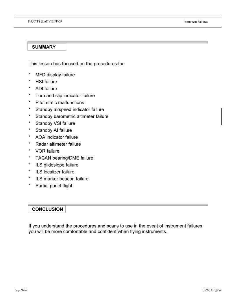
Page 9-26
Instrument FailuresT-45C TS & ADV BIFP-09
SUMMARY
This lesson has focused on the procedures for:
* MFD display failure
* HSI failure
* ADI failure
* Turn and slip indicator failure
* Pitot static malfunctions
* Standby airspeed indicator failure
* Standby barometric altimeter failure
* Standby VSI failure
* Standby AI failure
* AOA indicator failure
* Radar altimeter failure
* VOR failure
* TACAN bearing/DME failure
* ILS glideslope failure
* ILS localizer failure
* ILS marker beacon failure
* Partial panel flight
CONCLUSION
If you understand the procedures and scans to use in the event of instrument failures,you will be more comfortable and confident when flying instruments.
(8-99) Original
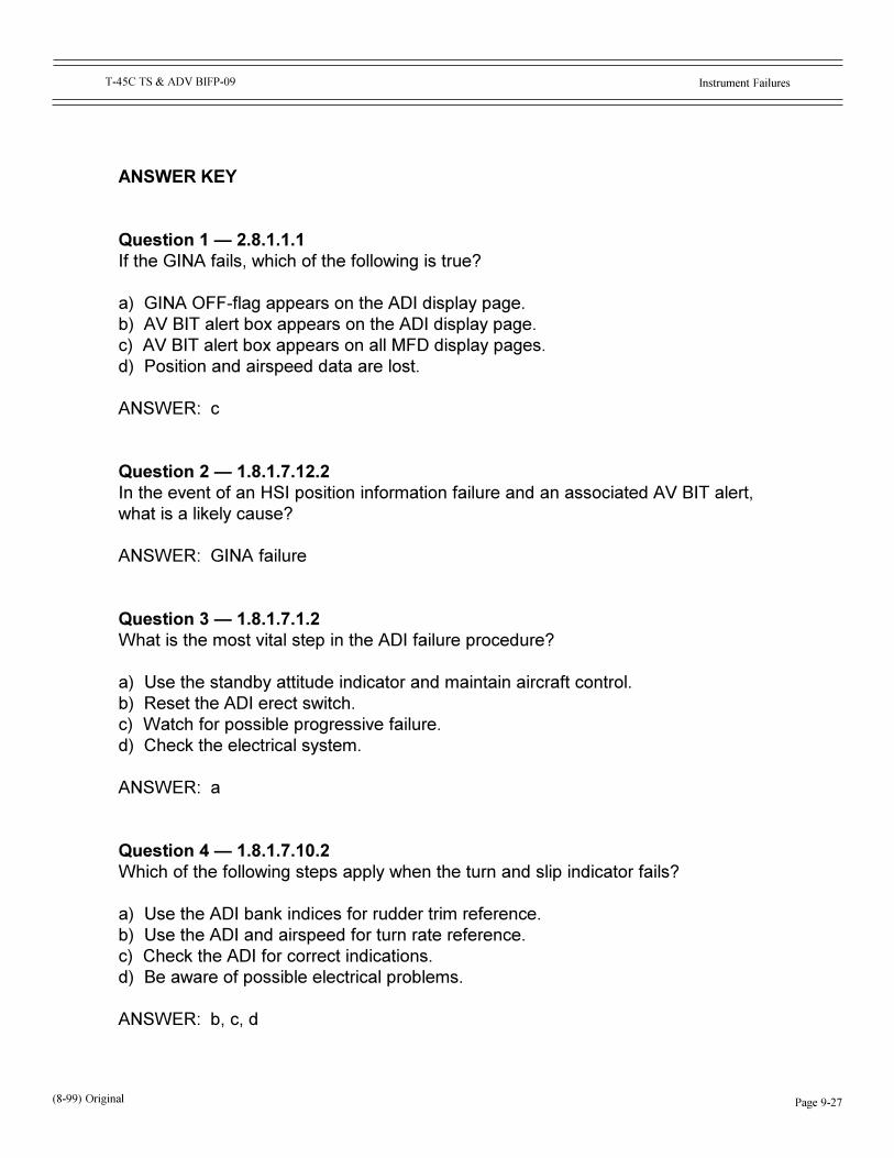
Instrument Failures
Page 9-27
T-45C TS & ADV BIFP-09
ANSWER KEY
Question 1 � 2.8.1.1.1If the GINA fails, which of the following is true?
a) GINA OFF-flag appears on the ADI display page.b) AV BIT alert box appears on the ADI display page.c) AV BIT alert box appears on all MFD display pages.d) Position and airspeed data are lost.
ANSWER: c
Question 2 � 1.8.1.7.12.2In the event of an HSI position information failure and an associated AV BIT alert,what is a likely cause?
ANSWER: GINA failure
Question 3 � 1.8.1.7.1.2What is the most vital step in the ADI failure procedure?
a) Use the standby attitude indicator and maintain aircraft control.b) Reset the ADI erect switch.c) Watch for possible progressive failure.d) Check the electrical system.
ANSWER: a
Question 4 � 1.8.1.7.10.2Which of the following steps apply when the turn and slip indicator fails?
a) Use the ADI bank indices for rudder trim reference.b) Use the ADI and airspeed for turn rate reference.c) Check the ADI for correct indications.d) Be aware of possible electrical problems.
ANSWER: b, c, d
(8-99) Original
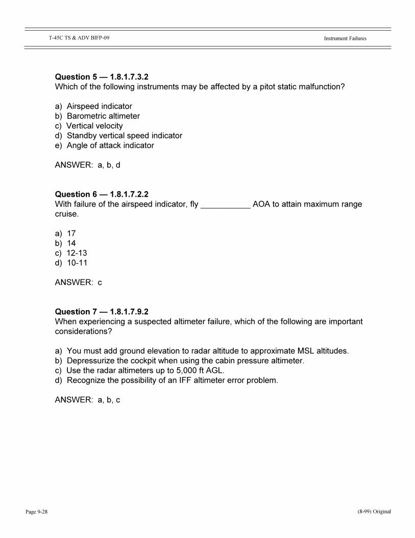
Page 9-28
Instrument FailuresT-45C TS & ADV BIFP-09
Question 5 � 1.8.1.7.3.2Which of the following instruments may be affected by a pitot static malfunction?
a) Airspeed indicatorb) Barometric altimeterc) Vertical velocityd) Standby vertical speed indicatore) Angle of attack indicator
ANSWER: a, b, d
Question 6 � 1.8.1.7.2.2With failure of the airspeed indicator, fly ___________ AOA to attain maximum rangecruise.
a) 17b) 14c) 12-13d) 10-11
ANSWER: c
Question 7 � 1.8.1.7.9.2When experiencing a suspected altimeter failure, which of the following are importantconsiderations?
a) You must add ground elevation to radar altitude to approximate MSL altitudes.b) Depressurize the cockpit when using the cabin pressure altimeter.c) Use the radar altimeters up to 5,000 ft AGL.d) Recognize the possibility of an IFF altimeter error problem.
ANSWER: a, b, c
(8-99) Original
Instrument Failures
Page 9-29
T-45C TS & ADV BIFP-09
Question 8 � 1.8.1.7.8.2With a failed VSI, you may cross-check the clock and altimeter to gauge verticalvelocity. A 600 fpm vertical velocity is equivalent to:
a) 200 ft change in 15 secondsb) 300 ft change in 20 secondsc) 200 ft change in 20 secondsd) 150 ft change in 20 seconds
ANSWER: c
Question 9 � 1.8.1.7.6.2Which of the following steps should be employed when dealing with failure of thestandby AI?
a) Reset the standby gyro inverter.b) Use the ADI display.c) Check the electrical system.d) Watch for possible progressive failure.
ANSWER: b, c, d
Question 10 � 1.8.1.7.4.2The correct procedure for dealing with an AOA indicator failure is to fly ________instead of angle of attack.
ANSWER: airspeed
Question 11 � 1.8.1.7.11.2Which of the following situations might cause the radar altimeter "OFF" flag toappear?
a) Power failureb) System turned offc) Aircraft attitude greater than +/- 40 degrees pitch or rolld) There is no radar altimeter indicator or "OFF" flag
ANSWER: d
(8-99) Original
Page 9-30
Instrument FailuresT-45C TS & ADV BIFP-09
Question 12In the event of a VOR failure, you should first cycle the frequency selector and checkwith ATC to see if the station is in operation. If the failure is not corrected, you shouldthen use _______.
ANSWER: An alternate approach which could be TACAN PAR/ASR or visual
Question 13In the event of TACAN bearing failure, you should first cycle the channel selector andTACAN receiver. If that does not restore TACAN operation, what should you do next?
ANSWER: Check with ATC to see if the station is still in operation.
Question 14One of the options you have in dealing with an ILS glideslope failure is to
a) check to see if the station is in operation.b) downgrade the approach to a localizer only.c) declare an emergency.d) use the CDI.
ANSWER: b
Question 15The correct procedure for dealing with an ILS localizer failure that occurs while flyingthe approach is to
a) reset the ILS circuit breaker.b) discontinue flying the ILS approach.c) declare an emergency.d) switch to VOR and continue.
ANSWER: b
Question 16In the event of an ILS marker beacon failure, you may continue the approach,provided you can use published ___________, __________, or ________, to identifythe FAF.
ANSWER: TACAN/DME, radar, crossing radials
(8-99) Original

Instrument Failures
Page 9-31
T-45C TS & ADV BIFP-09
(8-99) Original
Question 17For partial panel flight, substitute the ______ for the ADI display.
ANSWER: standby AI

Page 9-32
Instrument FailuresT-45C TS & ADV BIFP-09
NOTES
(8-99) Original