Embed Size (px)
Citation preview
Basic Imaging PrinciplesChapter 1
Biomedical EngineeringDr. Mohamed Bingabr
University of Central Oklahoma
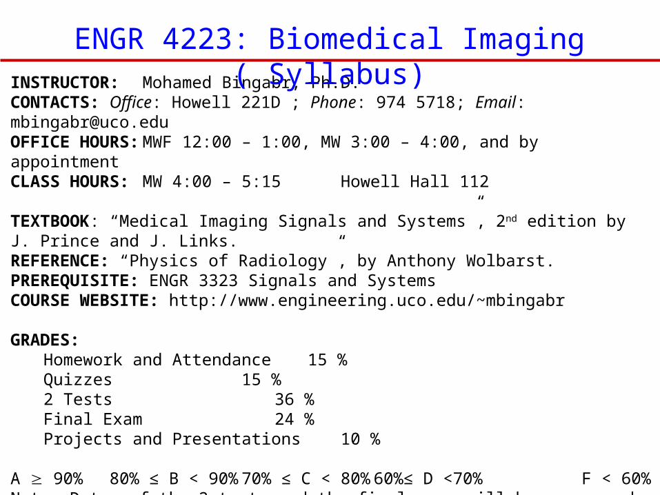
INSTRUCTOR: Mohamed Bingabr, Ph.D.CONTACTS: Office: Howell 221D ; Phone: 974 5718; Email: [email protected] HOURS:MWF 12:00 – 1:00, MW 3:00 – 4:00, and by appointmentCLASS HOURS: MW 4:00 – 5:15 Howell Hall 112 TEXTBOOK: “Medical Imaging Signals and Systems”, 2nd edition by J. Prince and J. Links.REFERENCE: “Physics of Radiology”, by Anthony Wolbarst.PREREQUISITE: ENGR 3323 Signals and SystemsCOURSE WEBSITE: http://www.engineering.uco.edu/~mbingabr GRADES:
Homework and Attendance 15 %Quizzes 15 %2 Tests 36 %Final Exam 24 %Projects and Presentations 10 %
A 90% 80% ≤ B < 90% 70% ≤ C < 80% 60%≤ D <70% F < 60%Note: Dates of the 2 tests and the final exam will be announced during the semester. Quizzes will be given every Monday.
ENGR 4223: Biomedical Imaging ( Syllabus)
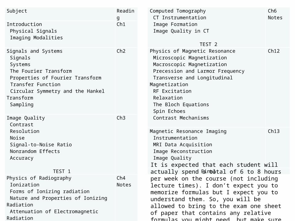
Subject ReadingIntroduction
Physical SignalsImaging Modalities
Ch1
Signals and SystemsSignalsSystemsThe Fourier TransformProperties of Fourier TransformTransfer FunctionCircular Symmetry and the Hankel TransformSampling
Ch2
Image QualityContrastResolutionNoiseSignal-to-Noise RatioNonrandom EffectsAccuracy
TEST 1
Ch3
Physics of RadiographyIonizationForms of Ionizing radiationNature and Properties of Ionizing RadiationAttenuation of Electromagnetic RadiationRadiation Dosimetry
Ch4Notes
Projection RadiographyInstrumentation Image Formation
Ch5
Computed TomographyCT InstrumentationImage FormationImage Quality in CT
TEST 2
Ch6Notes
Physics of Magnetic ResonanceMicroscopic MagnetizationMacroscopic MagnetizationPrecession and Larmor FrequencyTransverse and Longitudinal MagnetizationRF ExcitationRelaxationThe Bloch EquationsSpin EchoesContrast Mechanisms
Ch12
Magnetic Resonance ImagingInstrumentationMRI Data AcquisitionImage ReconstructionImage Quality
Ch13
Final
It is expected that each student will actually spend a total of 6 to 8 hours per week on the course (not including lecture times). I don’t expect you to memorize formulas but I expect you to understand them. So, you will be allowed to bring to the exam one sheet of paper that contains any relative formulas you might need, but make sure you know how to use them conceptually and not just mechanically.
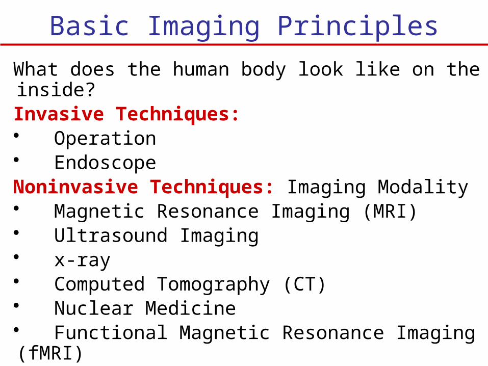
Basic Imaging Principles
What does the human body look like on the inside?Invasive Techniques: • Operation • EndoscopeNoninvasive Techniques: Imaging Modality• Magnetic Resonance Imaging (MRI) • Ultrasound Imaging• x-ray• Computed Tomography (CT)• Nuclear Medicine• Functional Magnetic Resonance Imaging (fMRI)• Positron Emission Tomography (PET)
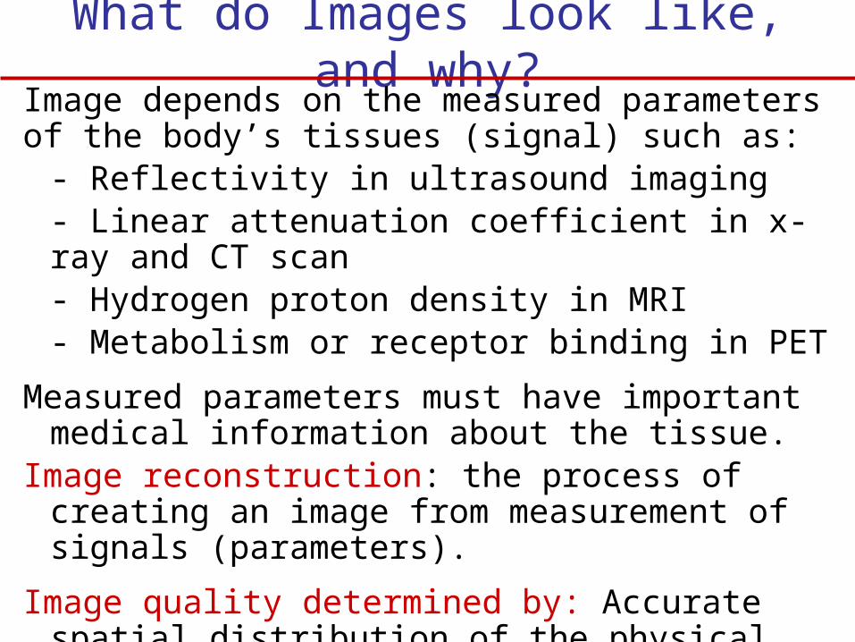
What do Images look like, and why?Image depends on the measured parameters of the body’s tissues (signal) such as:
- Reflectivity in ultrasound imaging- Linear attenuation coefficient in x-ray and CT scan- Hydrogen proton density in MRI- Metabolism or receptor binding in PET
Measured parameters must have important medical information about the tissue.
Image reconstruction: the process of creating an image from measurement of signals (parameters).
Image quality determined by: Accurate spatial distribution of the physical parameters. Resolution, Noise, Contrast, Geometric Distortion, Artifacts
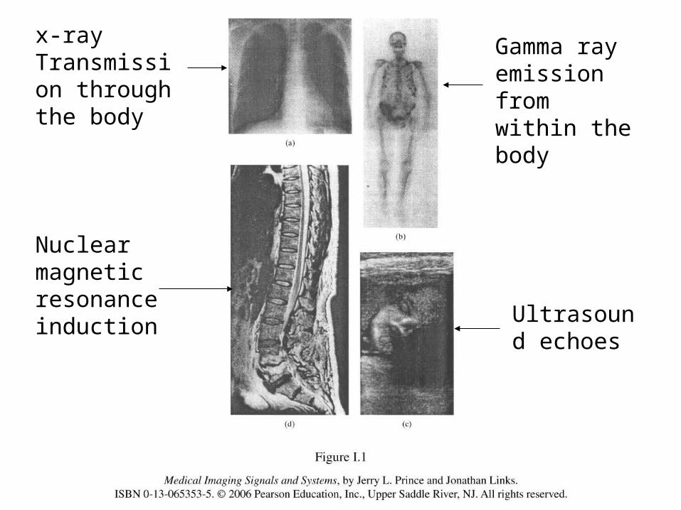
x-rayTransmission through the body
Gamma ray emission from within the body
Ultrasound echoes
Nuclear magnetic resonance induction
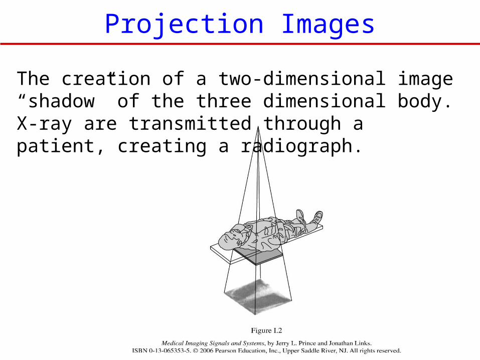
The creation of a two-dimensional image “shadow” of the three dimensional body. X-ray are transmitted through a patient, creating a radiograph.
Projection Images
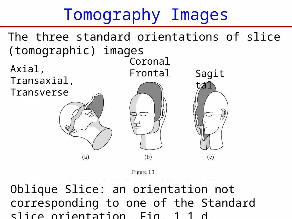
The three standard orientations of slice (tomographic) images
Axial, Transaxial, Transverse
CoronalFrontal Sagittal
Oblique Slice: an orientation not corresponding to one of the Standard slice orientation, Fig. 1.1 d.
Tomography Images
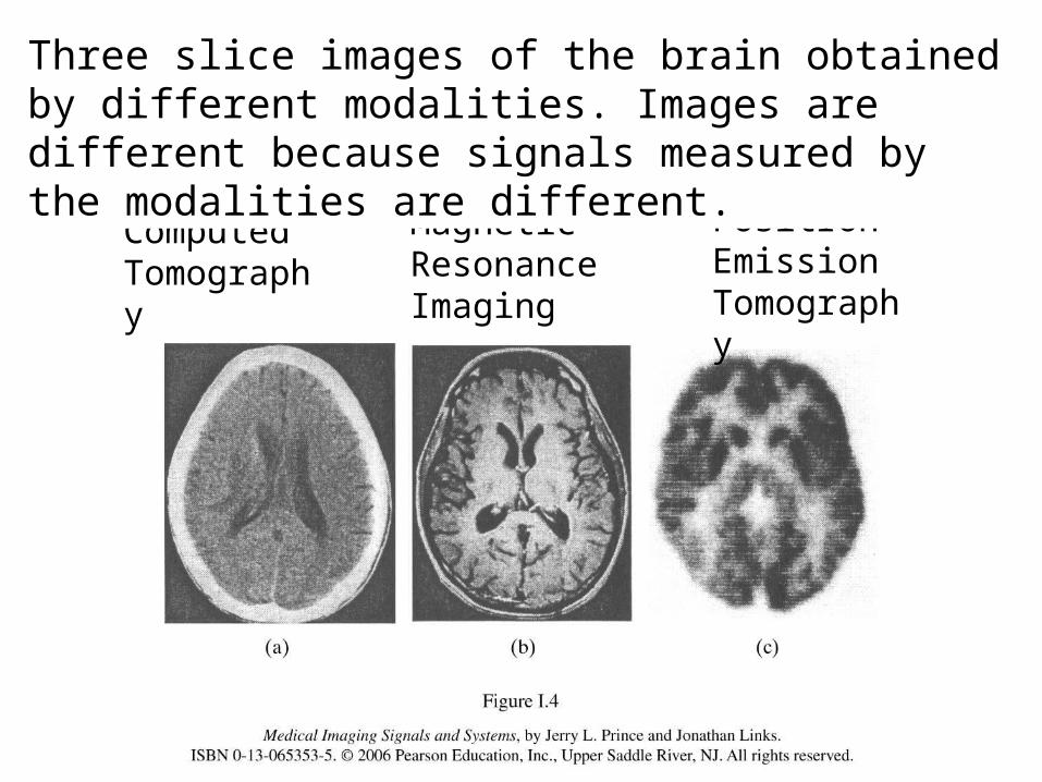
Computed Tomography
Magnetic Resonance Imaging
Positron Emission Tomography
Three slice images of the brain obtained by different modalities. Images are different because signals measured by the modalities are different.
IntroductionChapter 1
Biomedical EngineeringDr. Mohamed Bingabr
University of Central Oklahoma
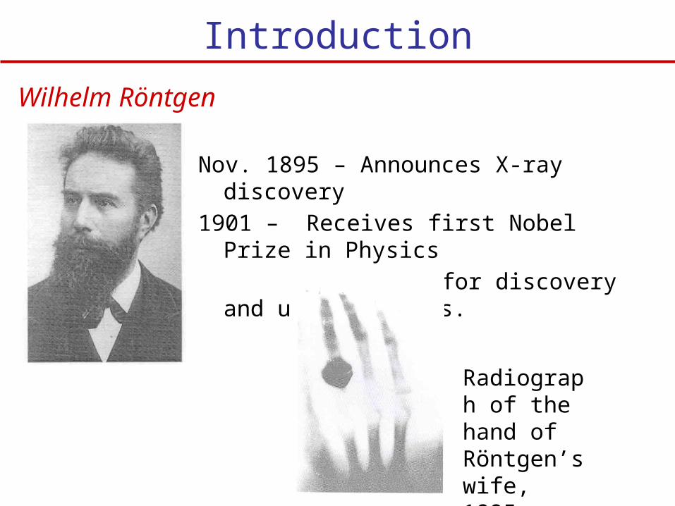
Nov. 1895 – Announces X-ray discovery
1901 – Receives first Nobel Prize in Physics
– Given for discovery and use of X-rays.
Wilhelm Röntgen
Radiograph of the hand of Röntgen’s wife, 1895.
Introduction
1940’s, 1950’s
Background laid for ultrasound and nuclear medicine
1960’s
Revolution in imaging – ultrasound and nuclear medicine
1972
CT (Computerized Tomography)
- true 3D imaging
- Allan Cormack and Hounsfield win Nobel Prize in 1979
1980’s
-In 1952 Felix Bloch and Edward Purcell received Nobel Prize in Physics for describing the phenomena of NMR
-In 1991 Richard Ernst received Nobel Prize in chemistry for a paper describing the use of MRI in medicine in 1973.
- In 2003 Paul Lauterbur and Peter Mansfield received Nobel Prize for developing Key method in MRI image construction.
Physical Signal
Detection of physical signals arising from the body and transform these signals to images.
Typical signals - Transmission of x-ray through the body ( Projection radiography) - Emission of gamma rays from radiotracer in the body (NM) - Reflection of ultrasonic waves within the body (in ultrasound imaging) - Precession of spin systems in a large magnetic field (MRI)
All signals above use Electromagnetic waves (EM) except the ultrasound imaging.
f 1/ f Energy
Physical Signal
Characteristics of spectrum that are useful for medical imaging
For Electromagnetic Imaging > 1 Angstrom (Ao) : Energy is highly attenuated by the bodyl < 0.01 Angstrom : Energy is too high and less contrast
Unit of energy for EM is electron volts (eV): 1 eV is the amount of energy an electron gains when accelerated across 1 volt potential.Useful energy for medical imaging: 25 k eV – 500 k eV
For Ultrasound ImagingIn ultrasound image resolution is poor for long wavelength, and attenuation is too high for short wavelength. Ideal frequency range for ultrasound imaging is 1 to 20 MHz
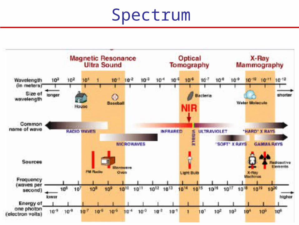
Spectrum
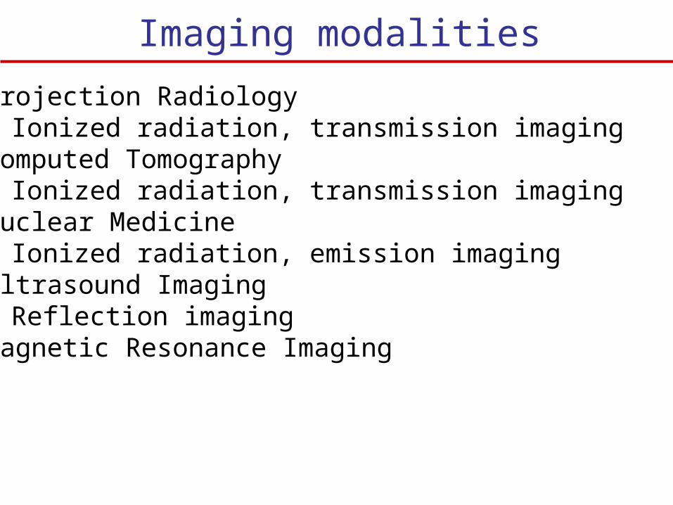
Imaging modalities
1. Projection Radiology- Ionized radiation, transmission imaging
2. Computed Tomography- Ionized radiation, transmission imaging
3. Nuclear Medicine- Ionized radiation, emission imaging
4. Ultrasound Imaging- Reflection imaging
5. Magnetic Resonance Imaging
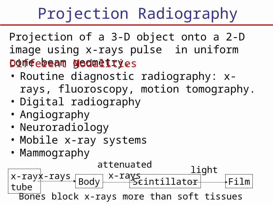
Projection Radiography
Projection of a 3-D object onto a 2-D image using x-rays pulse in uniform cone beam geometry.Different Modalities• Routine diagnostic radiography: x-rays,
fluoroscopy, motion tomography.• Digital radiography• Angiography• Neuroradiology• Mobile x-ray systems• Mammography
x-raytube
Body Scintillator Filmx-rays
attenuatedx-rays
Bones block x-rays more than soft tissues
light
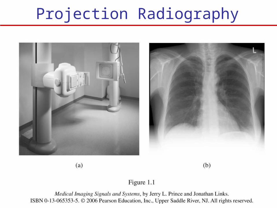
Projection Radiography
Computed Tomography (CT-scan)
The x-rays are collimated (restricted in their geometric spread) to travel within an approximate 2-D “Fan beam”
CT collects multiple projections of the same tissues from different orientations by moving the x-ray source around the body.
CT systems have rows of digital detectors whose signals are inputted to a computer. The computer reconstruct cross sections (slice) of the human body.
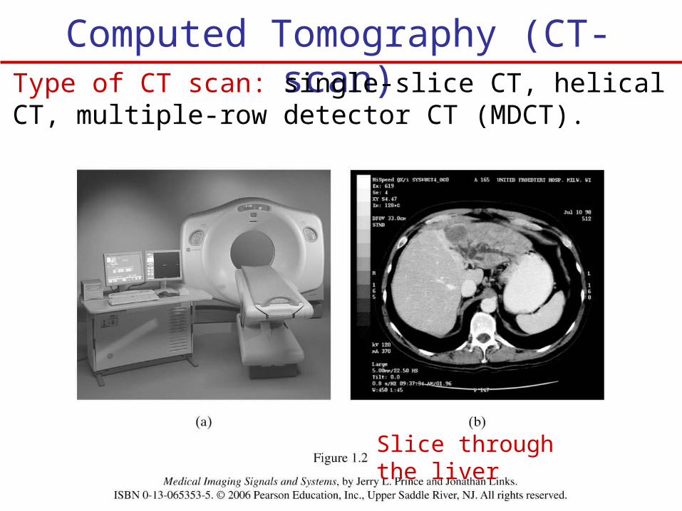
Computed Tomography (CT-scan)Type of CT scan: single-slice CT, helical CT, multiple-row detector CT (MDCT).
Slice through the liver
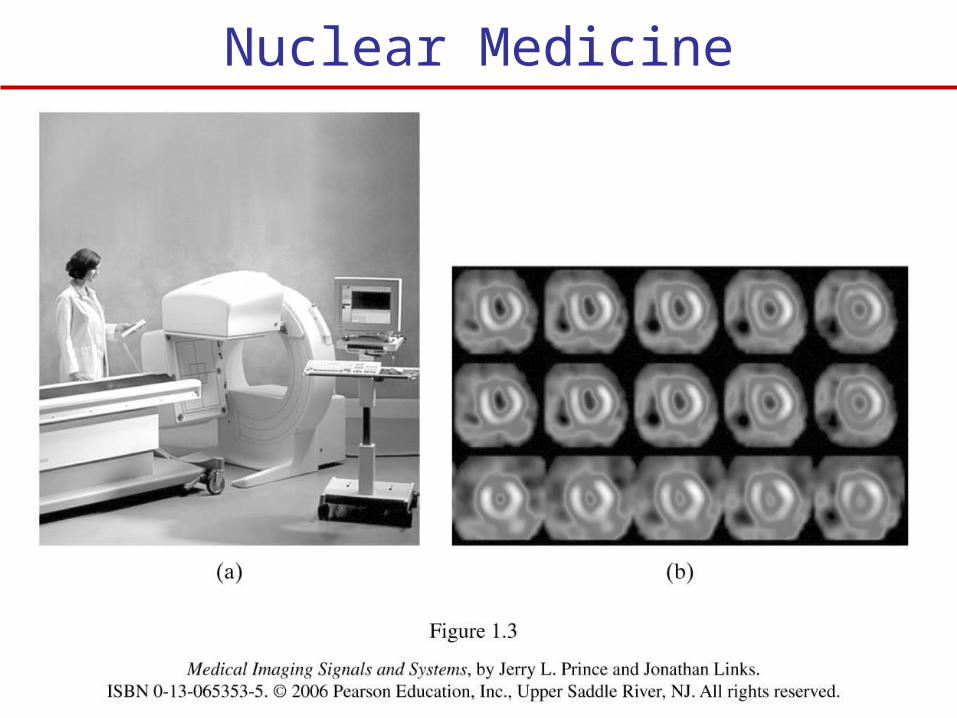
Nuclear Medicine Imaging (NMI)
NMI is imaging methods of the tissue physiology.
Imaging of gamma rays emitted by radioactive substance introduced into the body. These radiotracers are bound to biological molecules that are naturally consumed by body tissues.
Nuclear medicine imaging reflects the local concentration of a radiotracer within the body. Since this concentration is tied to the physiological behavior of the carrier molecule within the body, nuclear medicine imaging is functional imaging methods.
Example radioactive iodine to study thyroid function.
Nuclear Medicine
Modalities of Nuclear Medicine:- Conventional radionuclide imaging or scintigraphy- Single-photon emission computed tomography
(SPECT)- Positron emission tomography (PET)
In Conventional and SPECT: a radioactive atom’s decay produces a single gamma ray, which may intercept the Anger camera (scintillation detector).
In PET, a radionuclide decay produces a positron, which immediately annihilates (with an electron) to produce two gamma rays flying off in opposite directions.
Nuclear Medicine
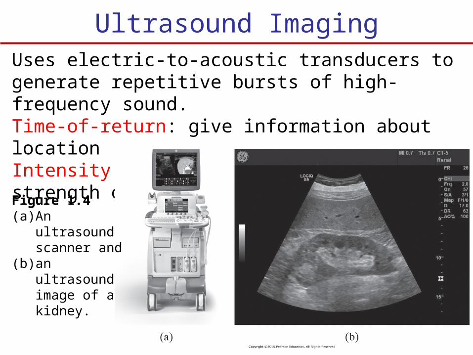
Ultrasound ImagingUses electric-to-acoustic transducers to generate repetitive bursts of high-frequency sound.Time-of-return: give information about locationIntensity: give information about the strength of a reflector
Figure 1.4 (a) An ultrasound
scanner and (b) an ultrasound
image of a kidney.
Modalities of Ultrasound
- A-mode imaging: generate one-dimensional waveform. Does not produce image but provide detail information about rapid or subtle motion (heart valve).
- B-mode imaging: cross-sectional anatomical imaging. - M-mode imaging: generate a succession of A-mode
signals and displayed as image in computer screen. Used to measure time-varying displacement such as a heart valve.
- Doppler imaging: uses the property of frequency and phase shift caused by moving objects. Phase shift is converted to sound that reveal information about motion such as blood flow.
- Nonlinear imaging: higher resolution, greater depth, image different properties of tissues.
Magnetic Resonance Imaging (MRI)
MRI measure the hydrogen atoms density in tissues.- Hydrogen nucleus align itself with an external
Magnetic field- Radio frequency pulse cause hydrogen atoms to tip
a way from the direction of the external magnetic field.
- When excitation pulse end, hydrogen nucleus realign itself with the magnetic field and release a radio-frequency.
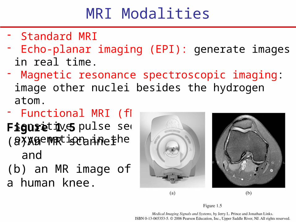
MRI Modalities- Standard MRI- Echo-planar imaging (EPI): generate images in real time.- Magnetic resonance spectroscopic imaging: image other
nuclei besides the hydrogen atom.- Functional MRI (fMRI): uses oxygenation-sensitive pulse
sequence to image blood oxygenation in the brain.
Figure 1.5 (a)An MR scanner and (b) an MR image of a human knee.
Multimodalities Imaging
Imaging system that consist of two different medical imaging modalities to reveal different properties of the human body.
CT Bones anatomyMRI Tissue anatomyPET tissue physiology
PET/CT systems improve the construction of the PET images.
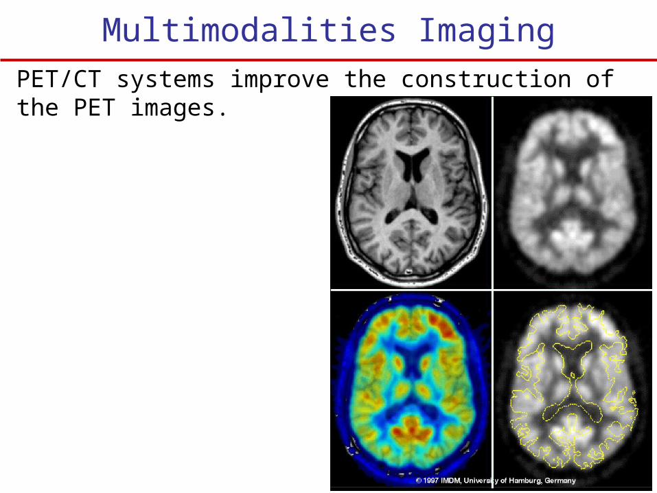
Multimodalities ImagingPET/CT systems improve the construction of the PET images.