Embed Size (px)
Citation preview

BASIC GUIDELINES PLANNING AND DESIGN HIGHWAY USING AutoCAd LAND DESKTOP COMPANION 2009
Ir. Welly Pradipta
Highway Engineering and Development - ITB
OUTLINE
1. Create New Project
2. Define Terrain
3. Set Horizontal Alignment
4. Stationing
5. Set Vertical Alignment
6. Create Cross Section
7. Create Volume Table
8. Solve a Problem “Surface Locked”
9. Credit
CREATE NEW PROJECT Chapter 1
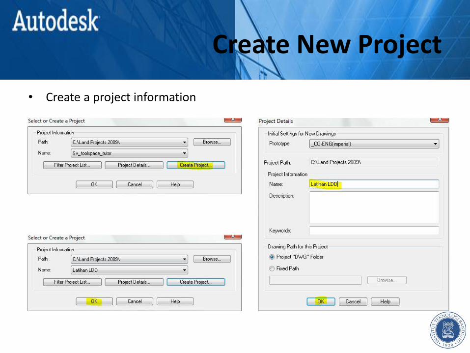
Create New Project
• Create a project information

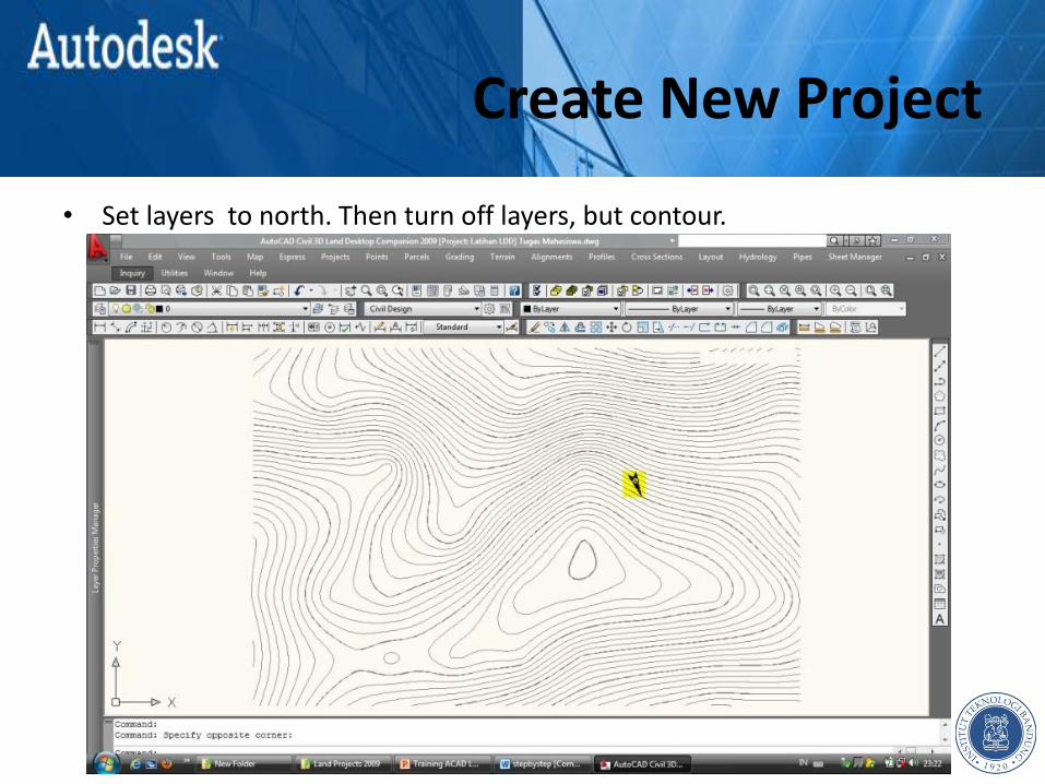
Create New Project
• Set layers to north. Then turn off layers, but contour.
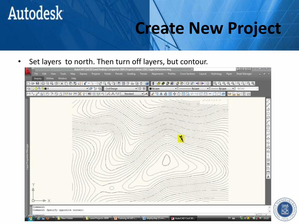
Create New Project
• Set layers to north. Then turn off layers, but contour.
Create New Project
• Set layers to north. Then turn off layers, but contour.
Create New Project
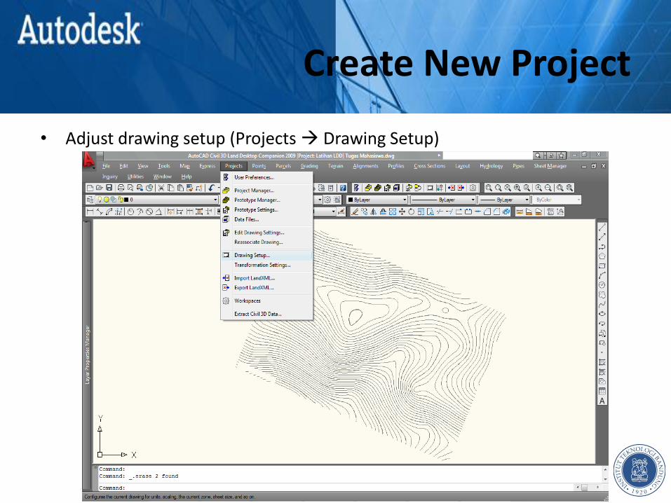
• Adjust drawing setup (Projects Drawing Setup)

Create New Project
• Adjust drawing setup (Projects Drawing Setup)

DEFINE TERRAIN Chapter 2
Define Terrain
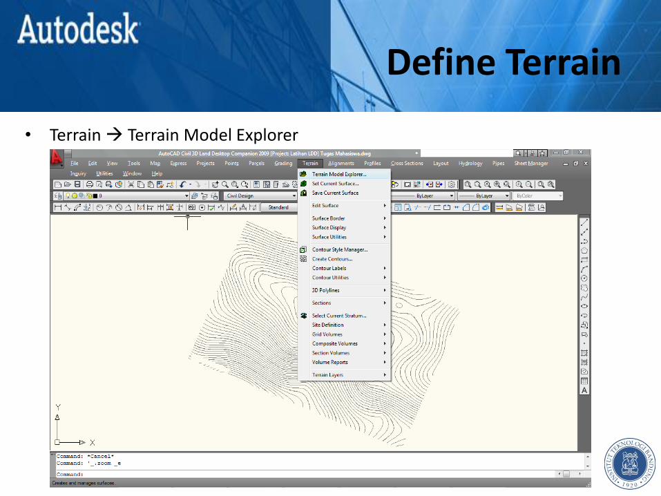
• Terrain Terrain Model Explorer
Define Terrain
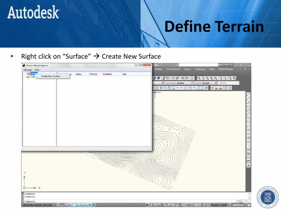
• Right click on “Surface” Create New Surface
Define Terrain
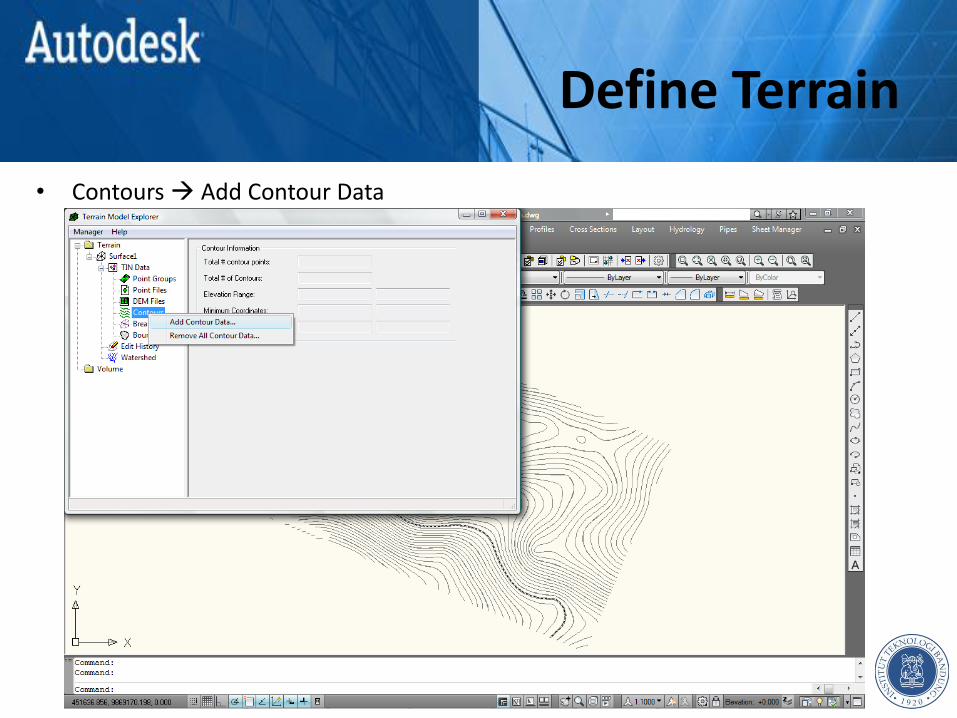
• Contours Add Contour Data
Define Terrain
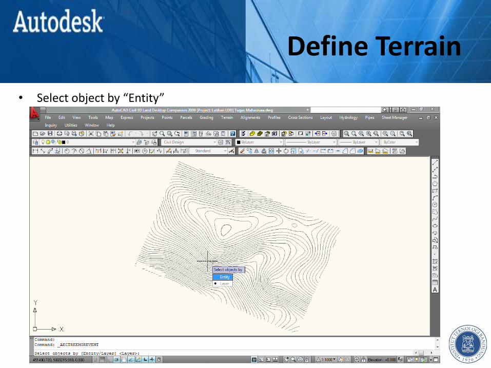
• Select object by “Entity”
Define Terrain
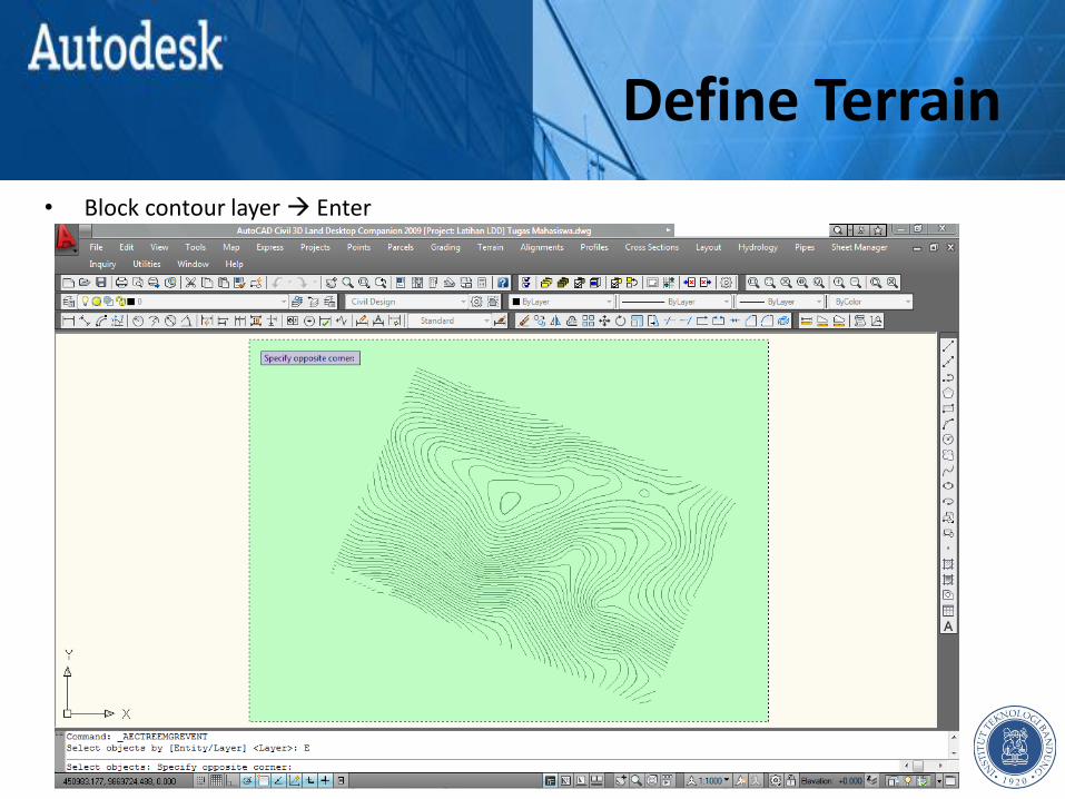
• Block contour layer Enter
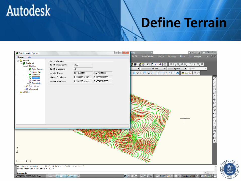
Define Terrain
SET HORIZONTAL ALIGNMENT Chapter 3
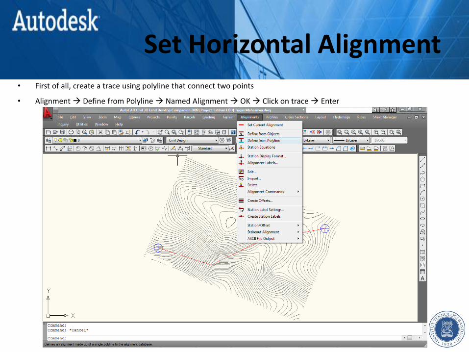
Set Horizontal Alignment • First of all, create a trace using polyline that connect two points
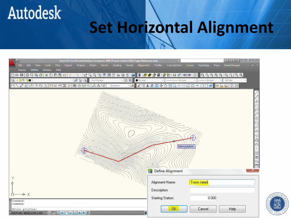
• Alignment Define from Polyline Named Alignment OK Click on trace Enter
Set Horizontal Alignment

Set Horizontal Alignment
• Edit horizontal curve
• Alignment Edit

Set Horizontal Alignment

Set Horizontal Alignment
Set Horizontal Alignment
Set Horizontal Alignment
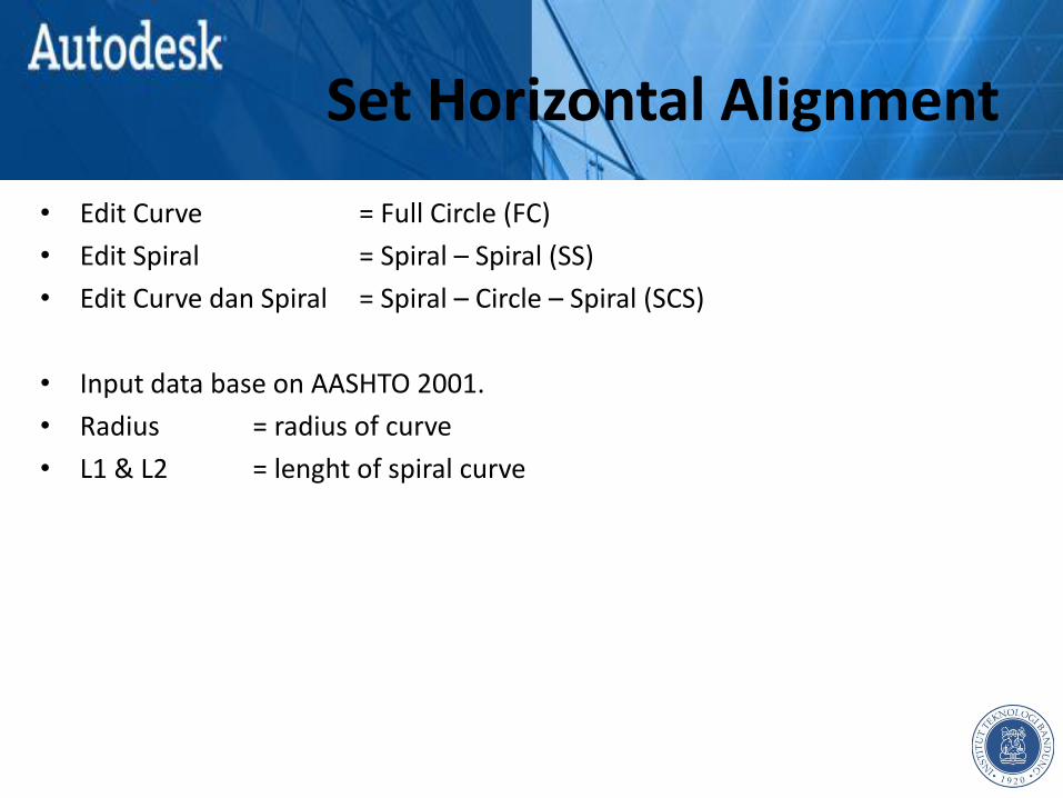
• Edit Curve = Full Circle (FC)
• Edit Spiral = Spiral – Spiral (SS)
• Edit Curve dan Spiral = Spiral – Circle – Spiral (SCS)
• Input data base on AASHTO 2001.
• Radius = radius of curve
• L1 & L2 = lenght of spiral curve
STATIONING Chapter 4

Stationing
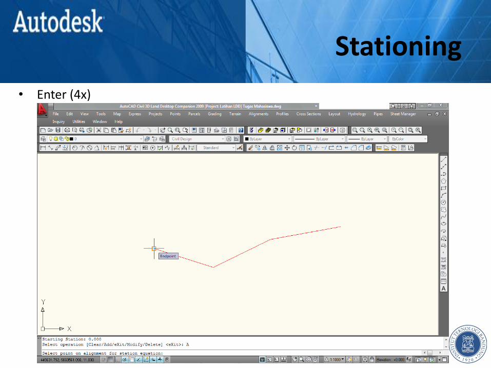
• Alignment Station Equation

Stationing
• Alignment Station Equation
Stationing
• Enter (4x)

Stationing
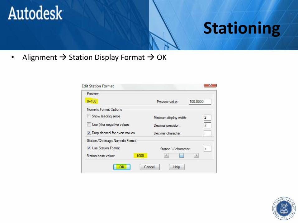
• Alignment Station Display Format
Stationing
• Alignment Station Display Format OK
Stationing
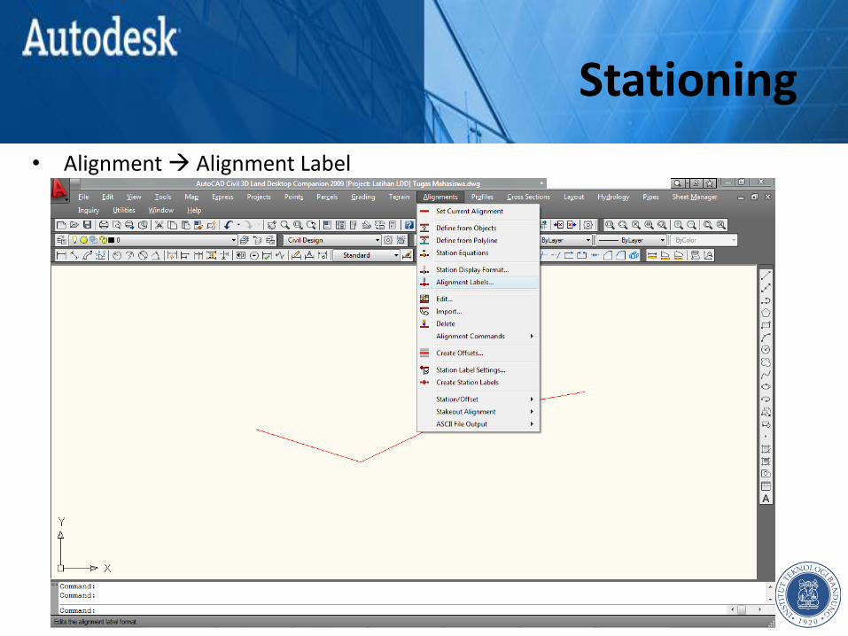
• Alignment Alignment Label

Stationing
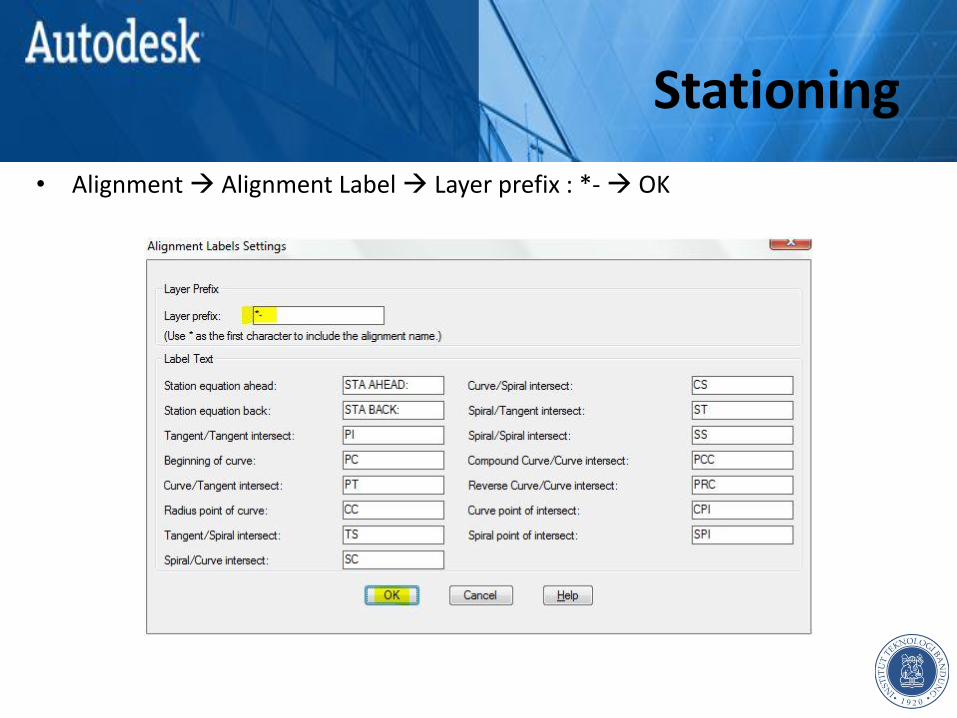
• Alignment Alignment Label Layer prefix : *- OK
Stationing
• Alignment Alignment Label Layer prefix : *- OK
Stationing
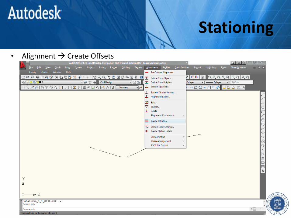
• Alignment Create Offsets
Stationing
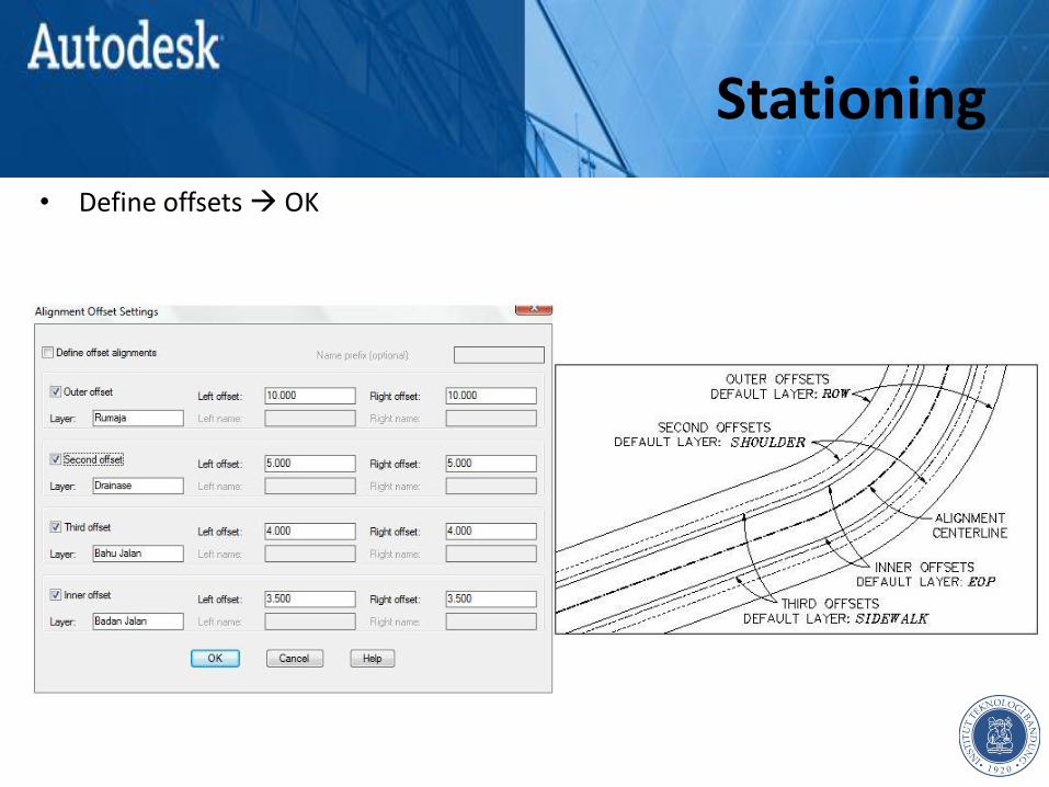
• Define offsets OK

Stationing
Stationing
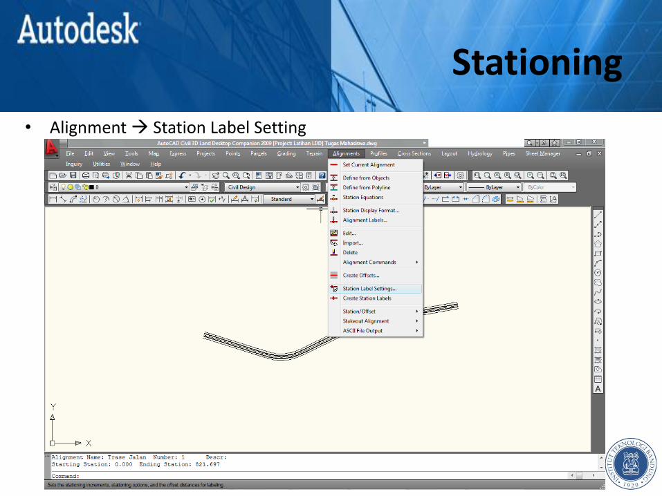
• Alignment Station Label Setting

Stationing
• Alignment Station Label Setting OK

Stationing
• Alignment Create Station Label
Stationing
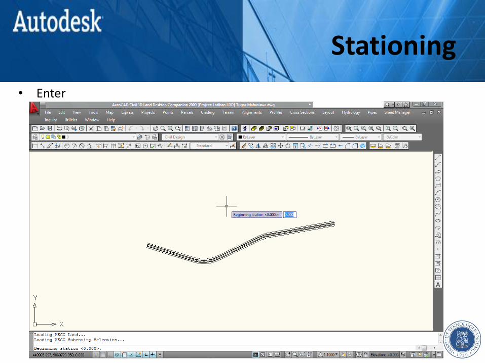
• Enter

Stationing
• Enter
Stationing
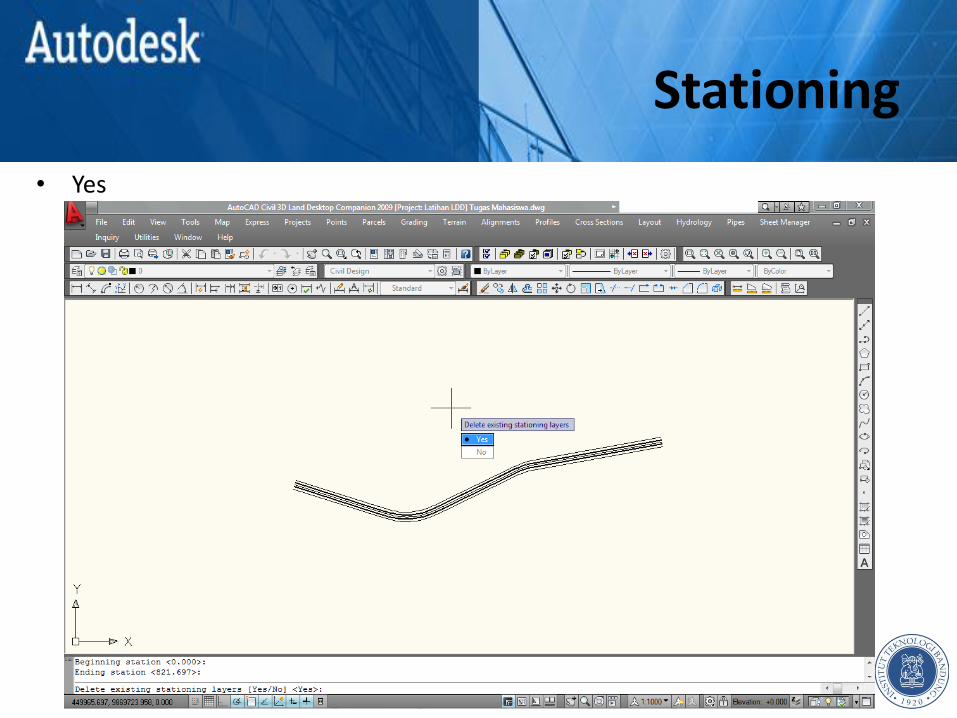
• Yes
Stationing

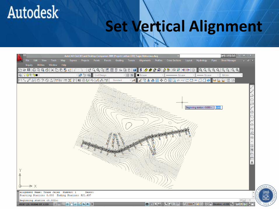
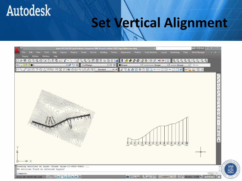
SET VERTICAL ALIGNMENT Chapter 5

Set Vertical Alignment
• Profile Surface Set Current Surface

Set Vertical Alignment
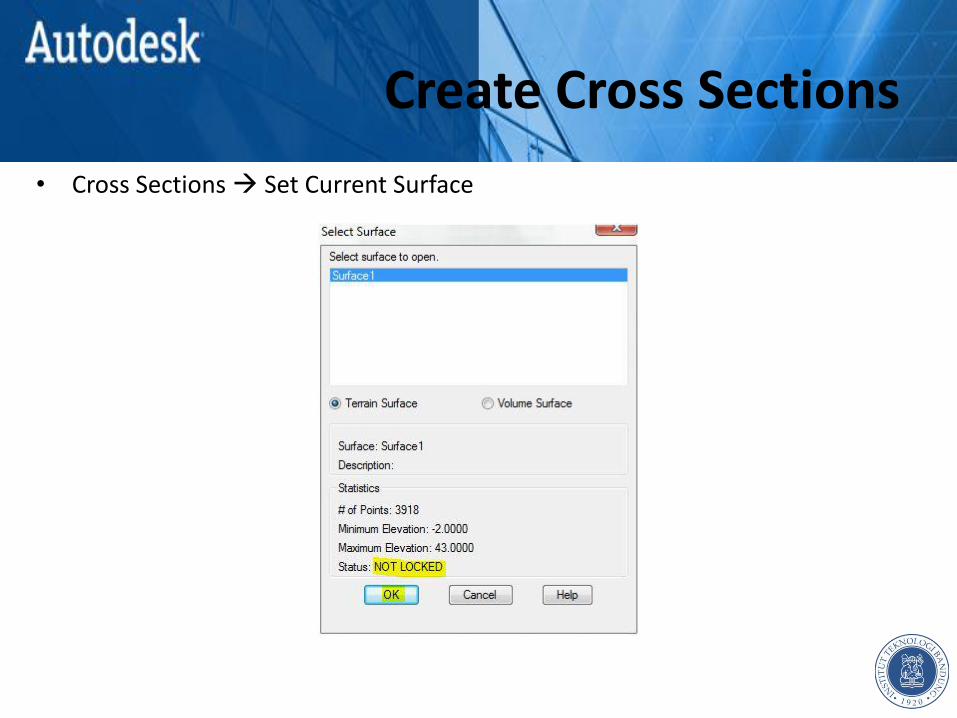
• Status : NOT LOCKED

Set Vertical Alignment
• Profile Existing Ground Sample From Surface
Set Vertical Alignment
Set Vertical Alignment
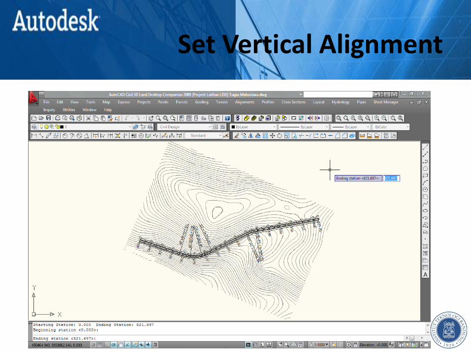
Set Vertical Alignment
Set Vertical Alignment
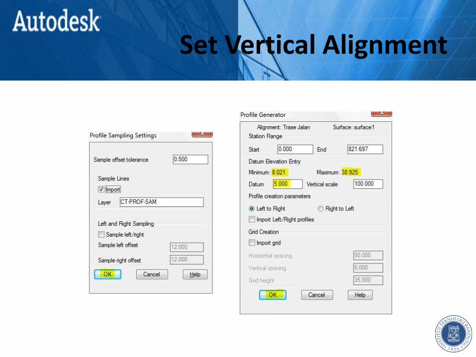
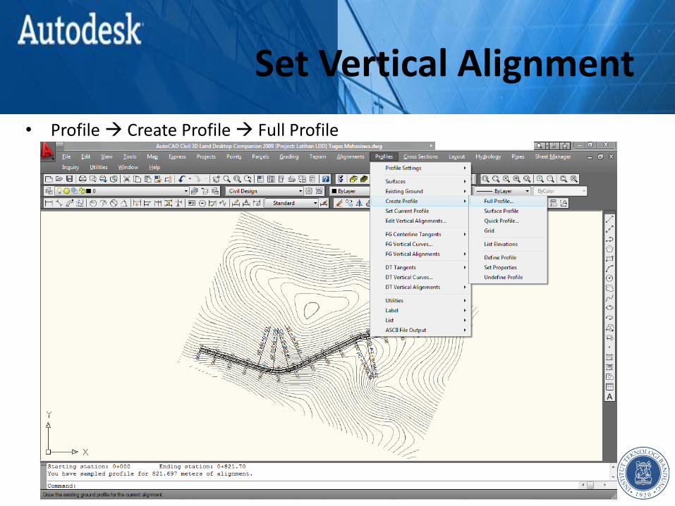
• Profile Create Profile Full Profile

Set Vertical Alignment
• Profile Create Profile Full Profile
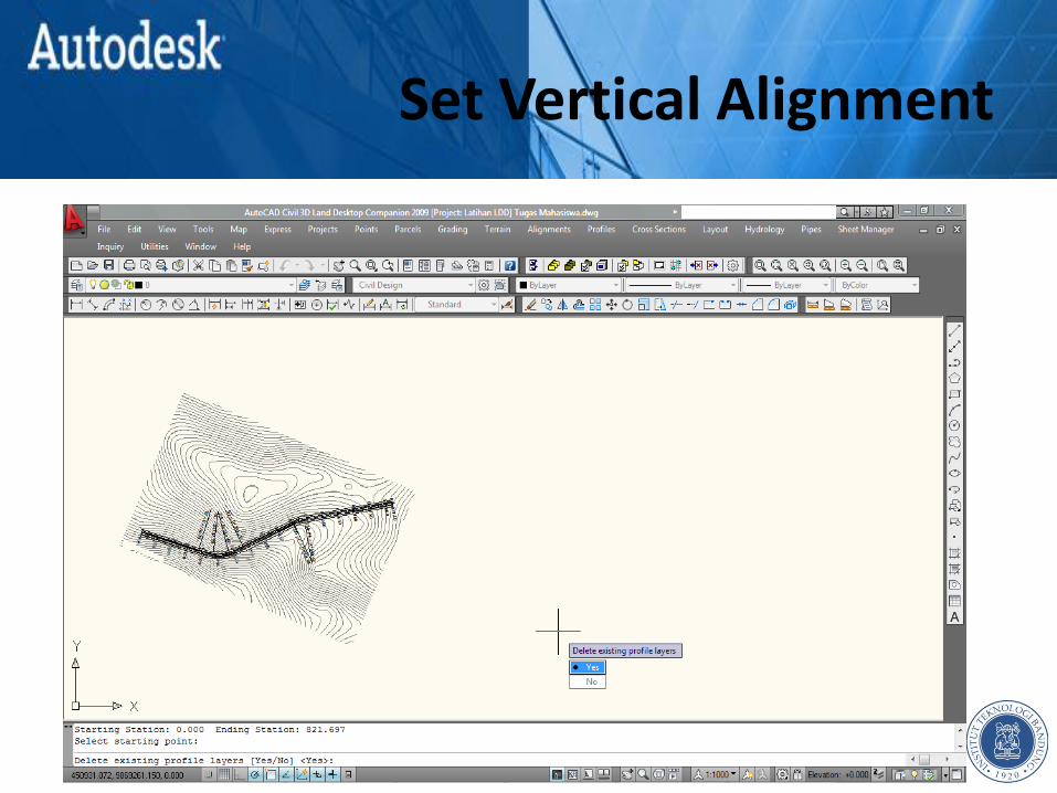
Set Vertical Alignment
Set Vertical Alignment

Set Vertical Alignment
Set Vertical Alignment
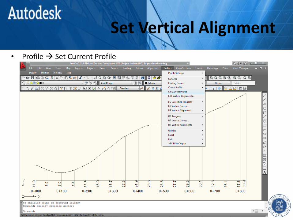
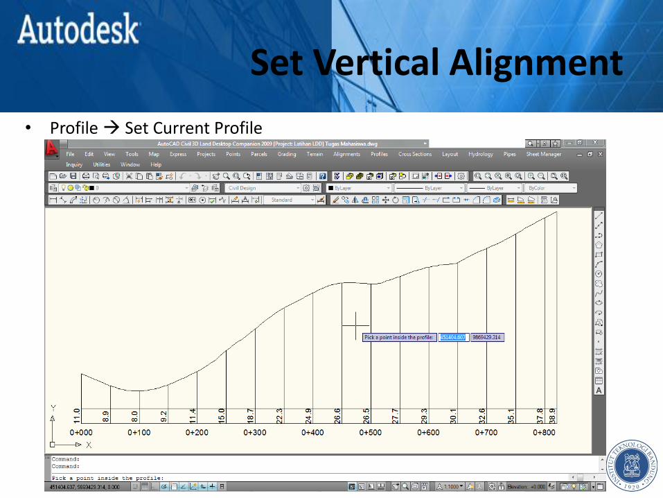
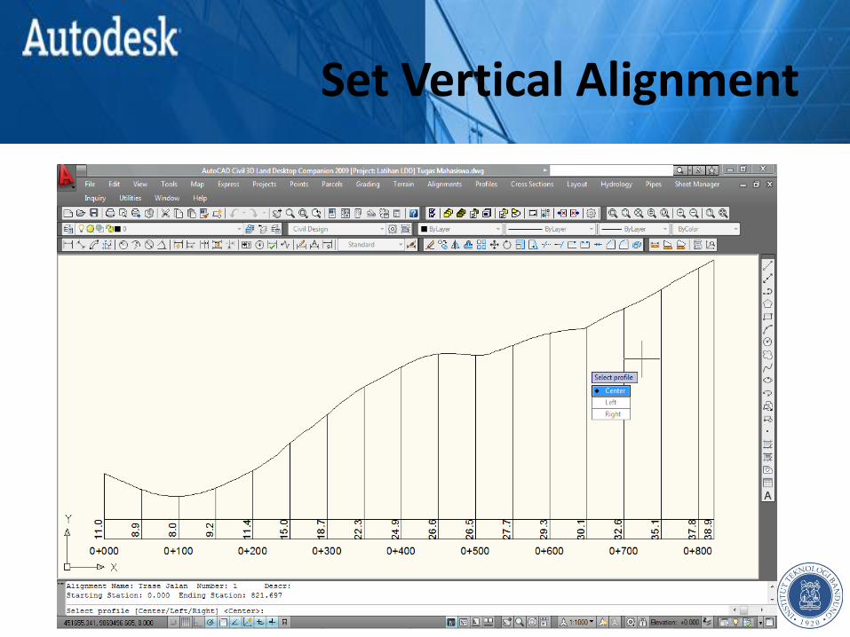
• Profile Set Current Profile
Set Vertical Alignment
• Profile Set Current Profile
Set Vertical Alignment
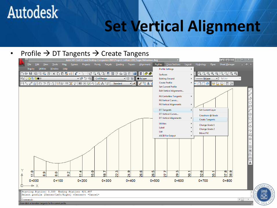
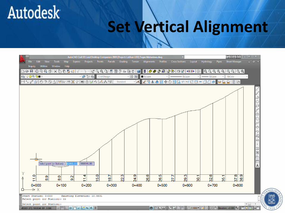
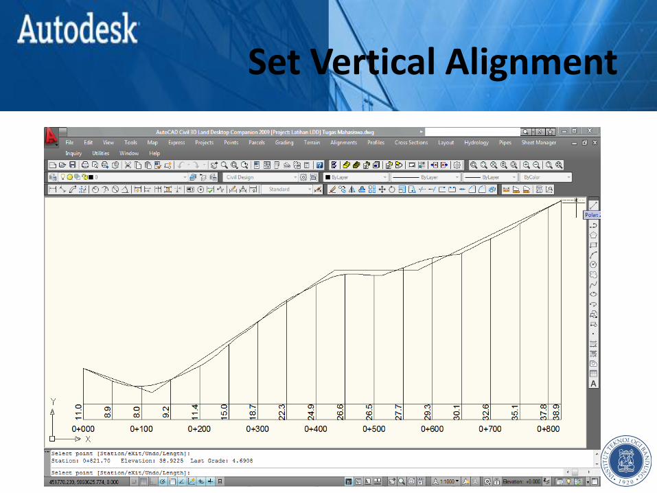
• Profile DT Tangents Create Tangens
Set Vertical Alignment
Set Vertical Alignment

Set Vertical Alignment

Set Vertical Alignment
Set Vertical Alignment
Set Vertical Alignment
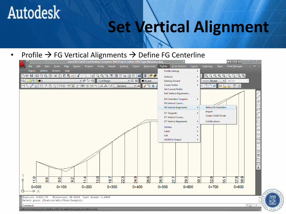
• Profile FG Vertical Alignments Define FG Centerline
Set Vertical Alignment
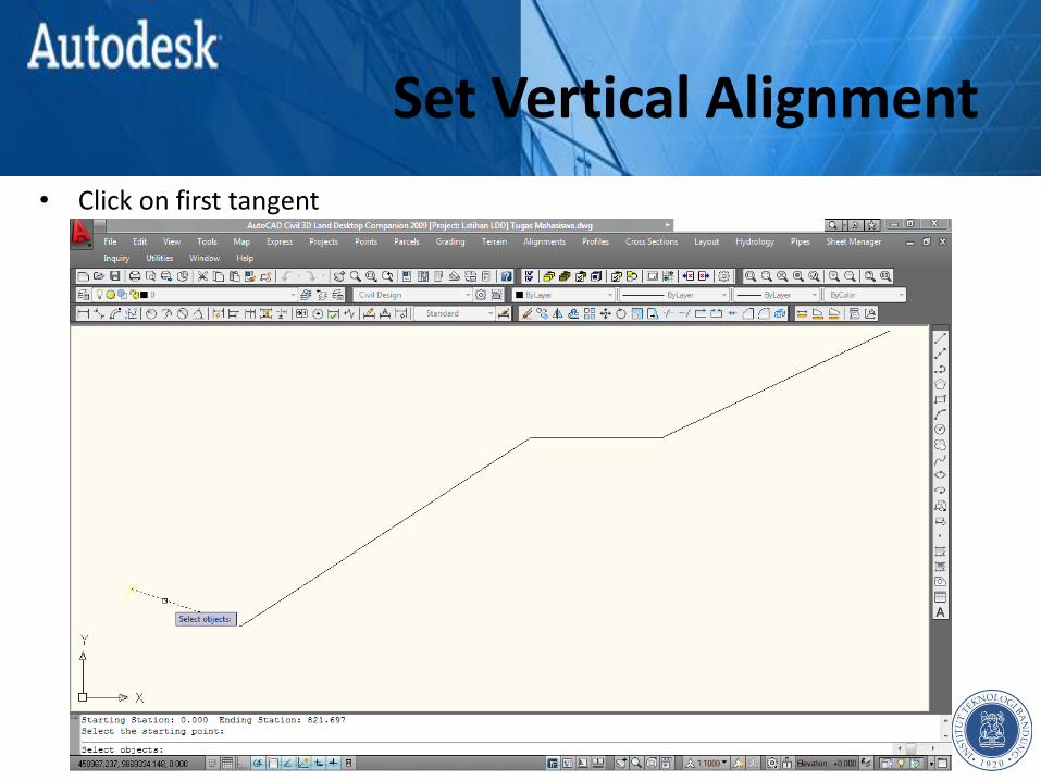
• Click on first tangent
Set Vertical Alignment
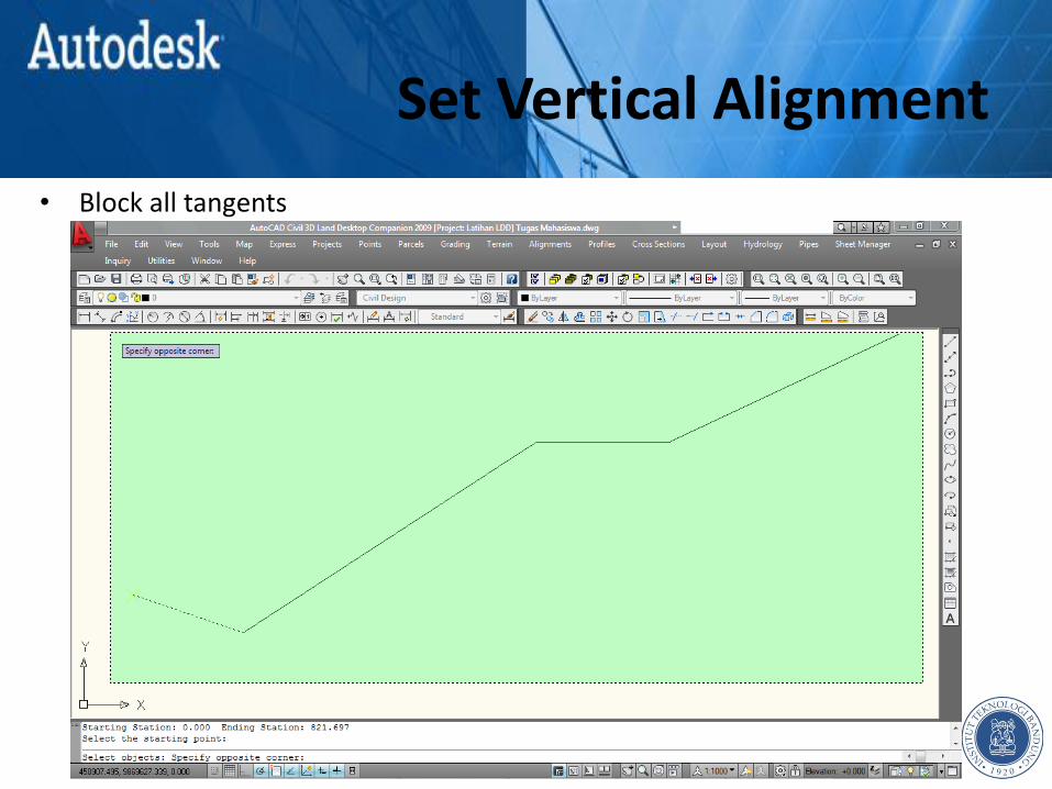
• Block all tangents
Set Vertical Alignment
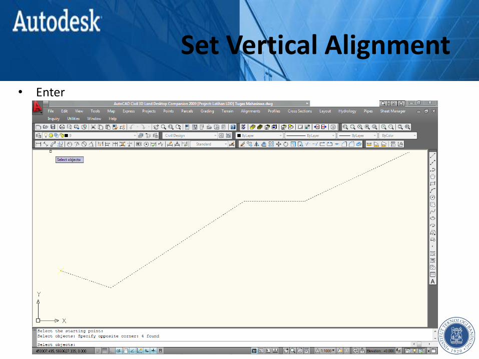
• Enter
Set Vertical Alignment
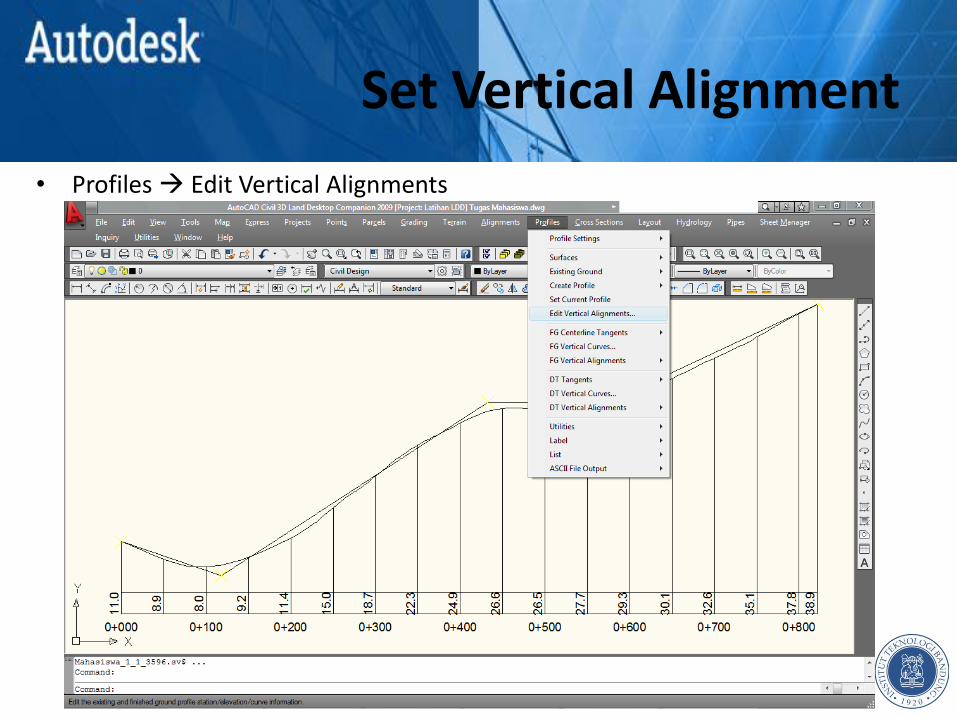
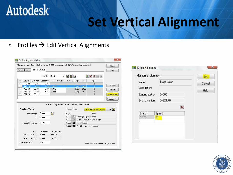
• Profiles Edit Vertical Alignments

Set Vertical Alignment
• Profiles Edit Vertical Alignments
Set Vertical Alignment
• Profiles Edit Vertical Alignments

Set Vertical Alignment
• Profiles Edit Vertical Alignments

Set Vertical Alignment
• Profiles Edit Vertical Alignments

Set Vertical Alignment
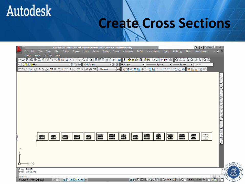
CREATE CROSS SECTIONS Chapter 6

Create Cross Sections
• Cross Sections Set Current Surface
Create Cross Sections
• Cross Sections Set Current Surface

Create Cross Sections
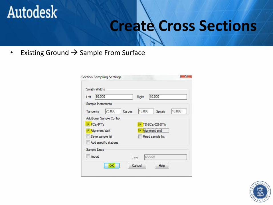
• Existing Ground Sample From Surface
Create Cross Sections
• Existing Ground Sample From Surface
Create Cross Sections
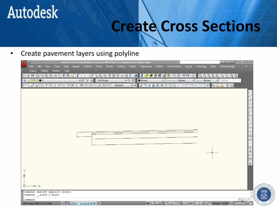
• Create pavement layers using polyline

Create Cross Sections
• Cross Sections Templates Define Template

Create Cross Sections

Create Cross Sections

Create Cross Sections

Create Cross Sections
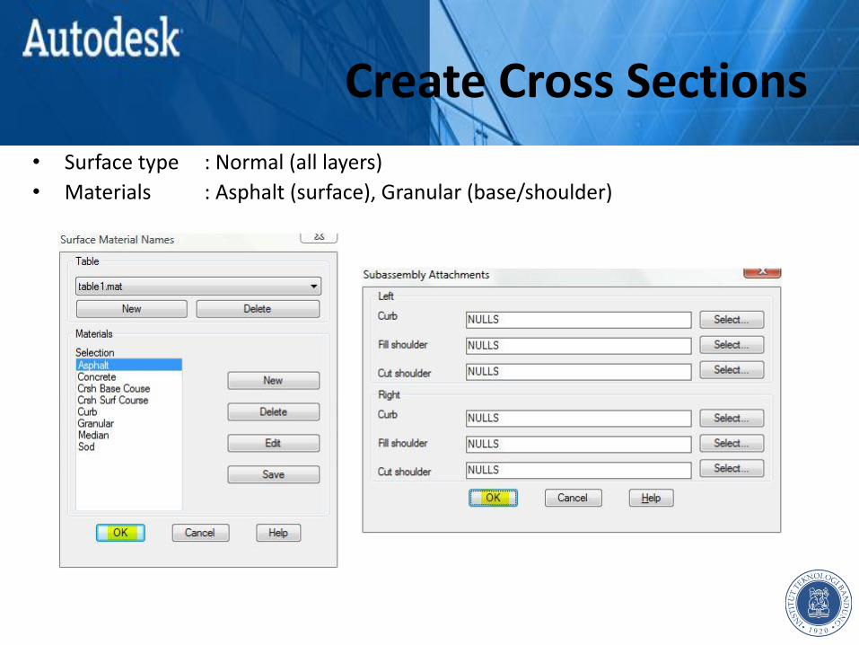
• Surface type : Normal (all layers)
Create Cross Sections
• Surface type : Normal (all layers)
• Materials : Asphalt (surface), Granular (base/shoulder)

Create Cross Sections
• Pick connection point out : left-top corner
Create Cross Sections
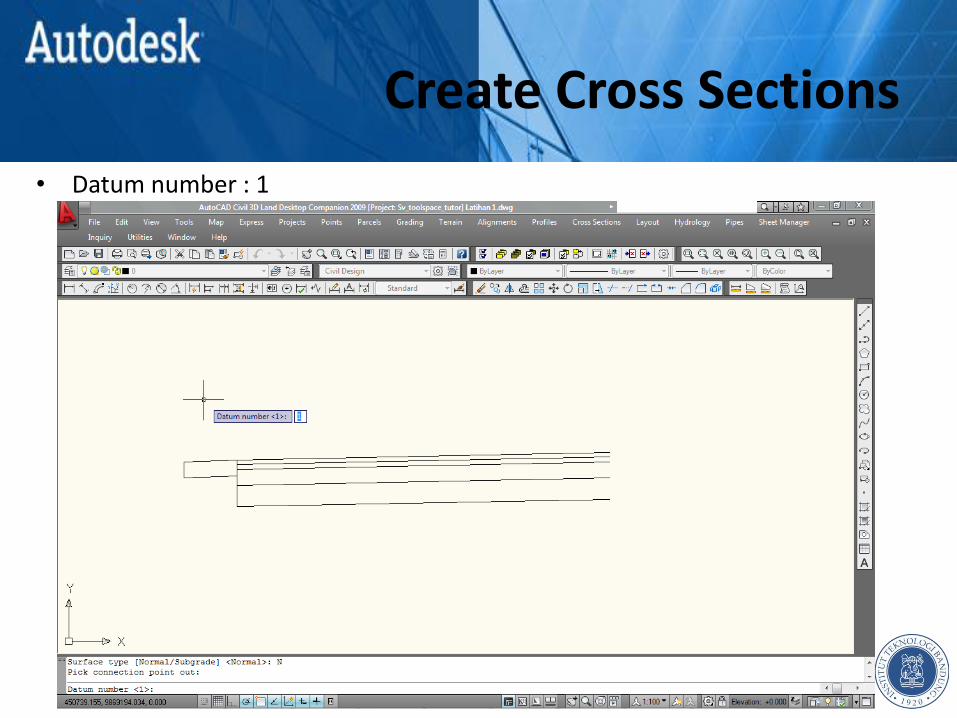
• Datum number : 1

Create Cross Sections
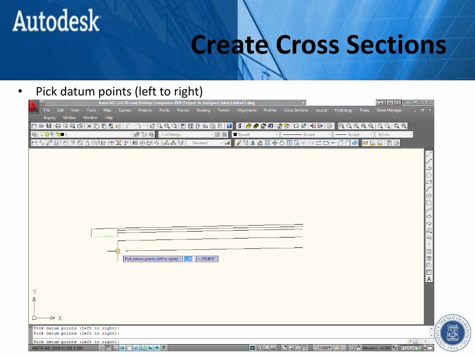
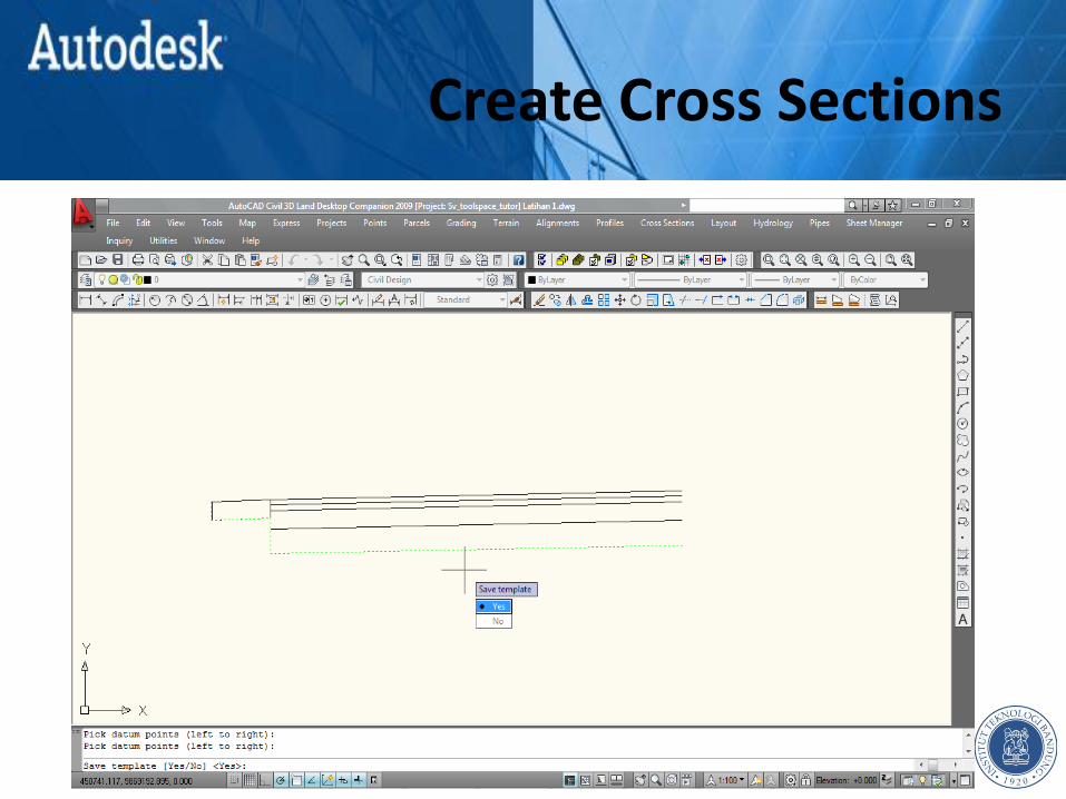
• Pick datum points (left to right)

Create Cross Sections
• Pick datum points (left to right)

Create Cross Sections
• Pick datum points (left to right)
Create Cross Sections
• Pick datum points (left to right)
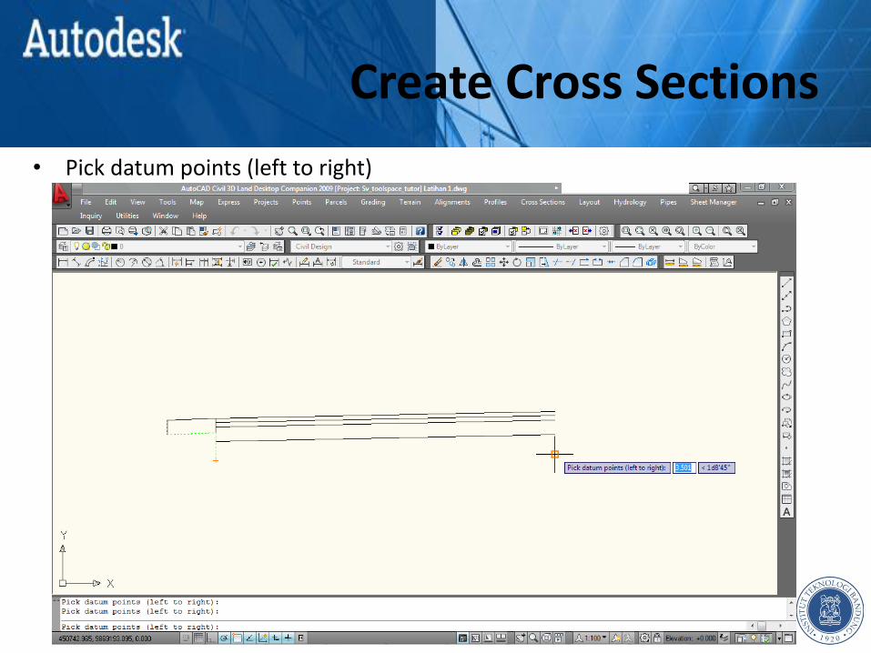
Create Cross Sections
• Pick datum points (left to right)
Create Cross Sections
Create Cross Sections
Create Cross Sections

Create Cross Sections
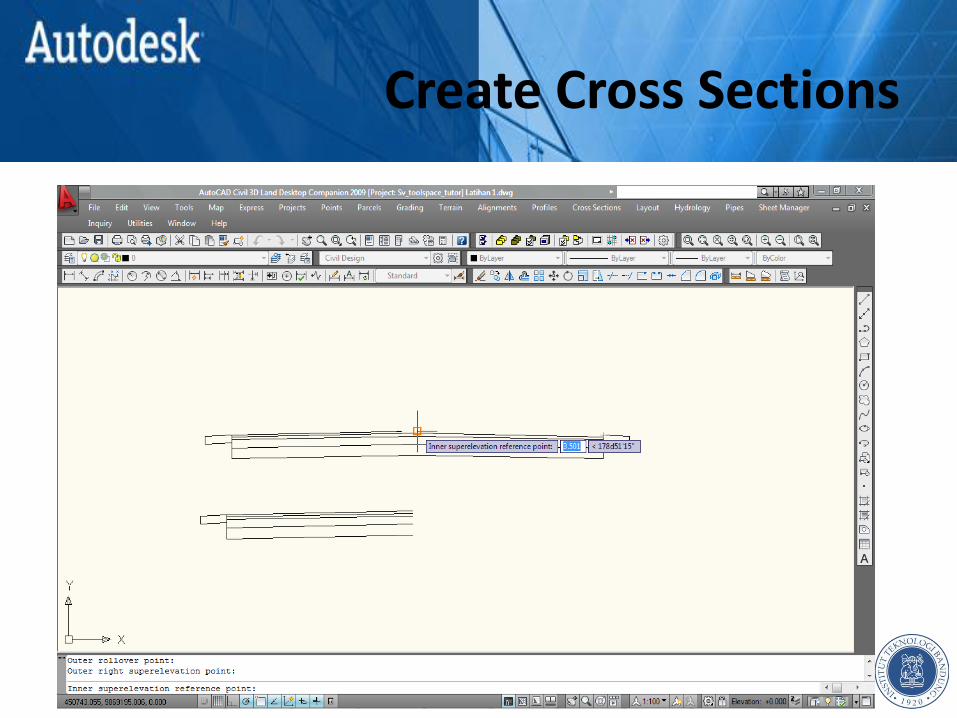
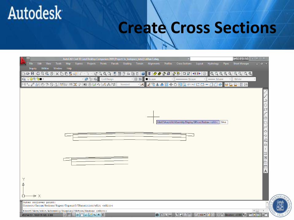
• Cross Sections Templates Edit Template

Create Cross Sections
Create Cross Sections

Create Cross Sections

Create Cross Sections

Create Cross Sections

Create Cross Sections
Create Cross Sections
Create Cross Sections
Create Cross Sections
Create Cross Sections

Create Cross Sections
Create Cross Sections

Create Cross Sections

Create Cross Sections

Create Cross Sections
Create Cross Sections
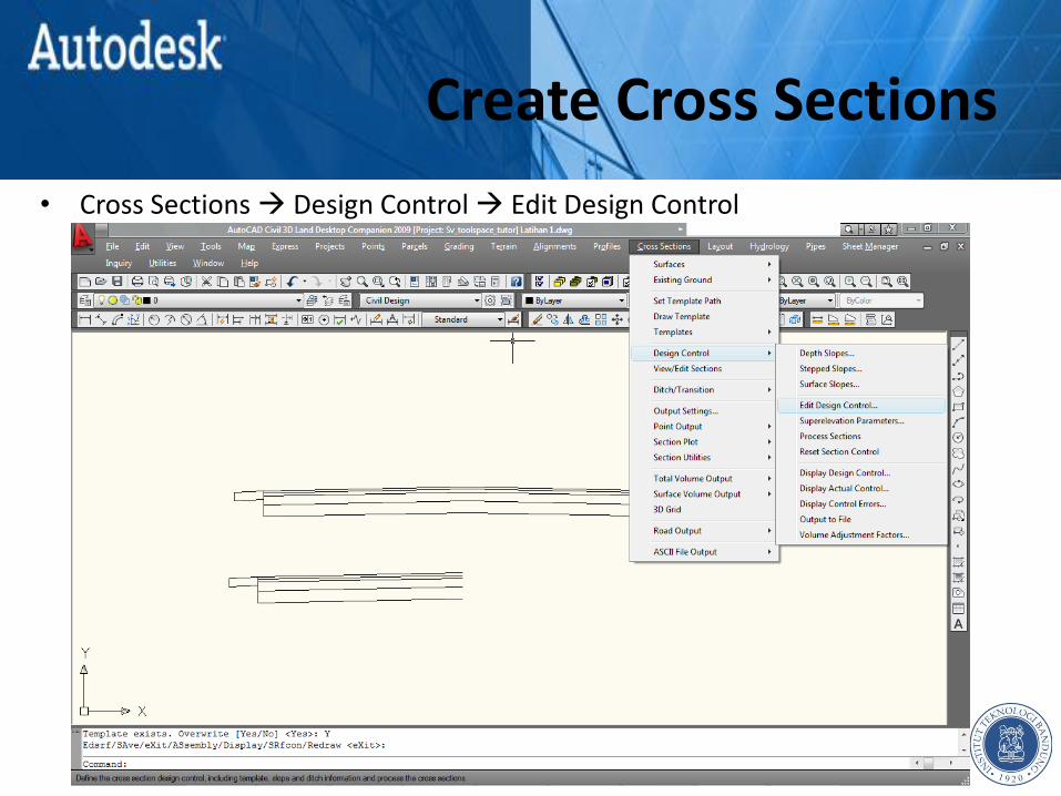
• Cross Sections Design Control Edit Design Control
Create Cross Sections
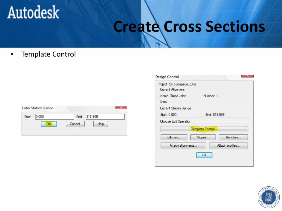
• Template Control
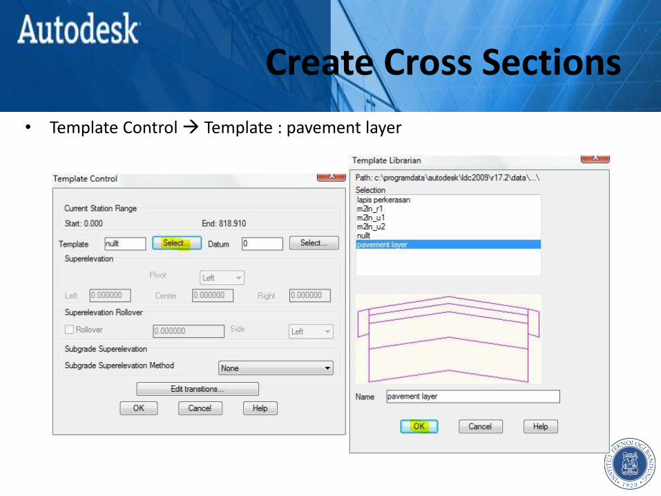
Create Cross Sections
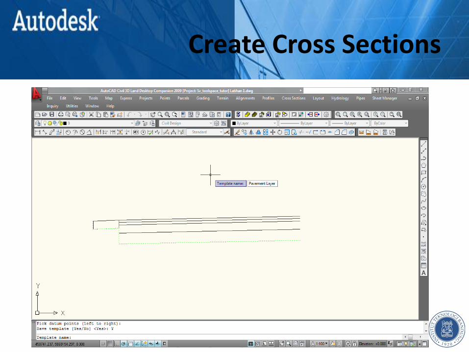
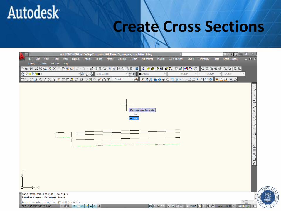
• Template Control Template : pavement layer
Create Cross Sections
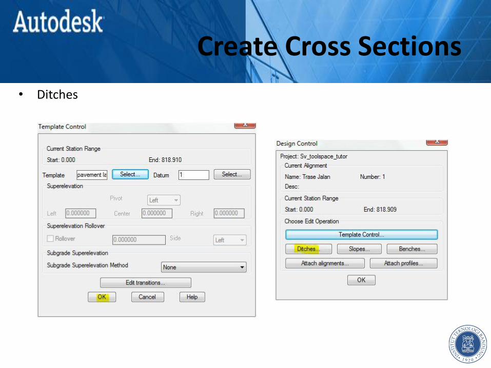
• Ditches
Create Cross Sections
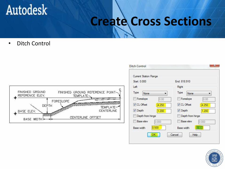
• Ditch Control
Create Cross Sections
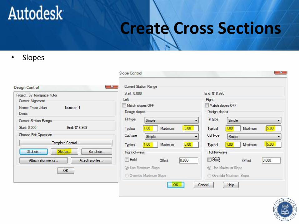
• Slopes
Create Cross Sections
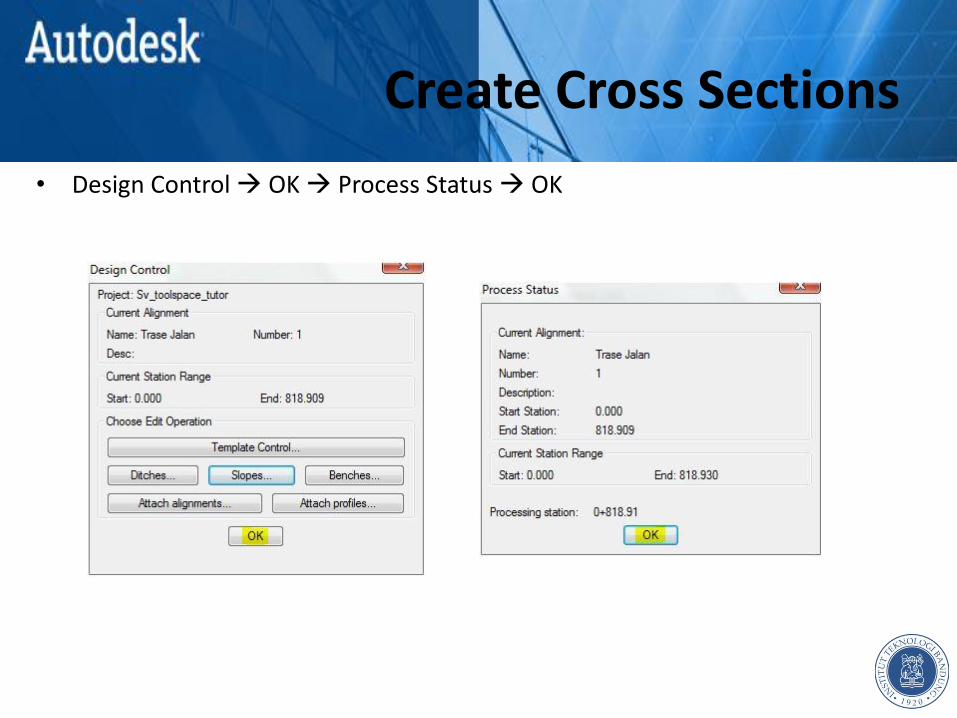
• Design Control OK Process Status OK

Create Cross Sections
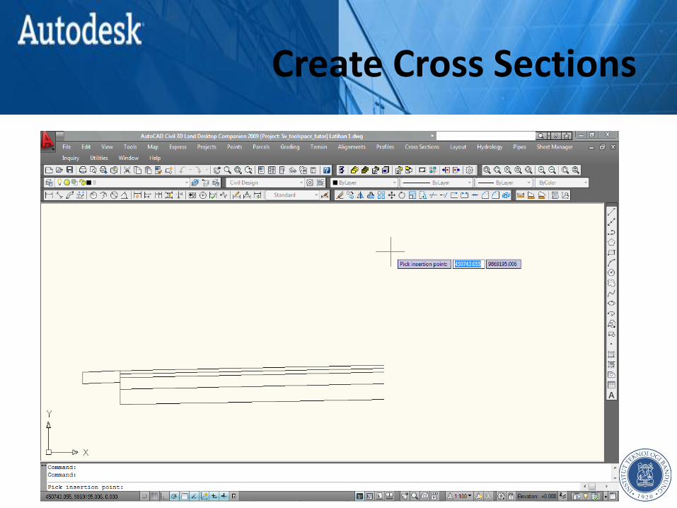
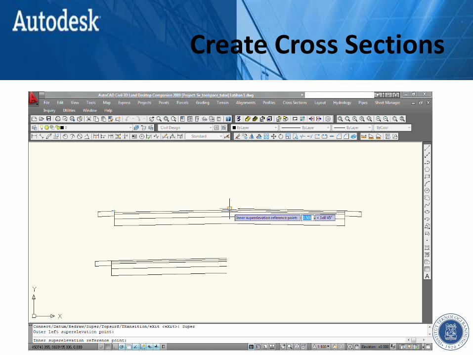
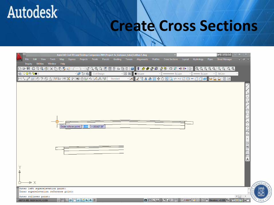
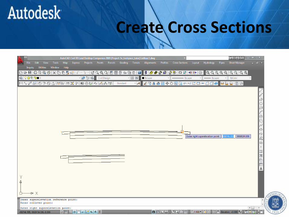
• Cross Sections Design Control Superelevation Parameters
Create Cross Sections
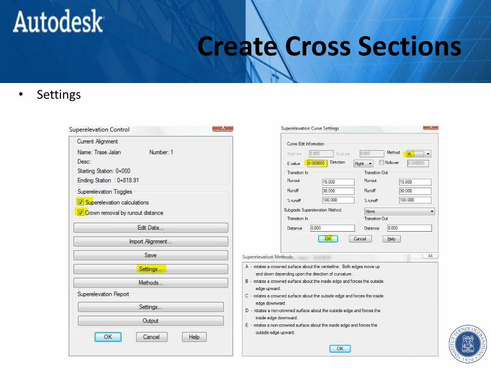
• Settings
Create Cross Sections
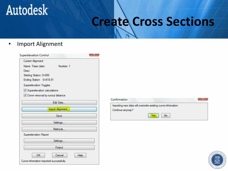
• Import Alignment
Create Cross Sections
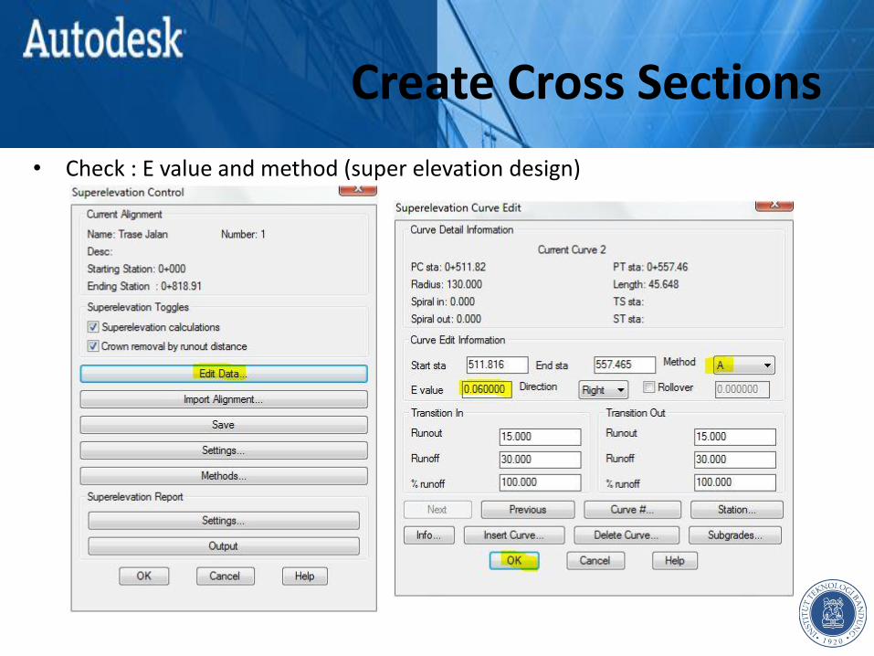
• Check : E value and method (super elevation design)
Create Cross Sections
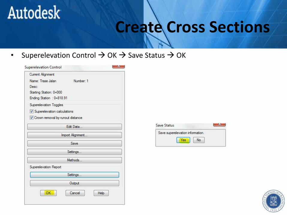
• Superelevation Control OK Save Status OK

Create Cross Sections
• Superelevation Section Sampling OK Process Status OK
Create Cross Sections
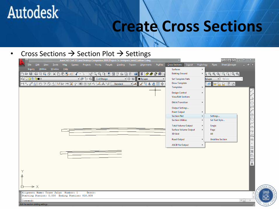
• Cross Sections Section Plot Settings
Create Cross Sections
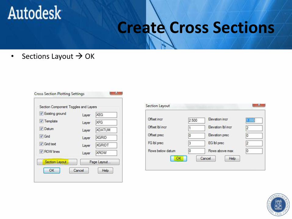
• Sections Layout OK
Create Cross Sections
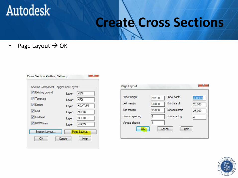
• Page Layout OK
Create Cross Sections
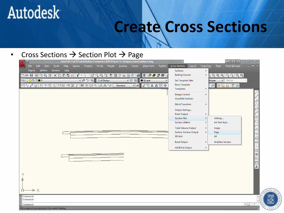
• Cross Sections Section Plot Page
Create Cross Sections
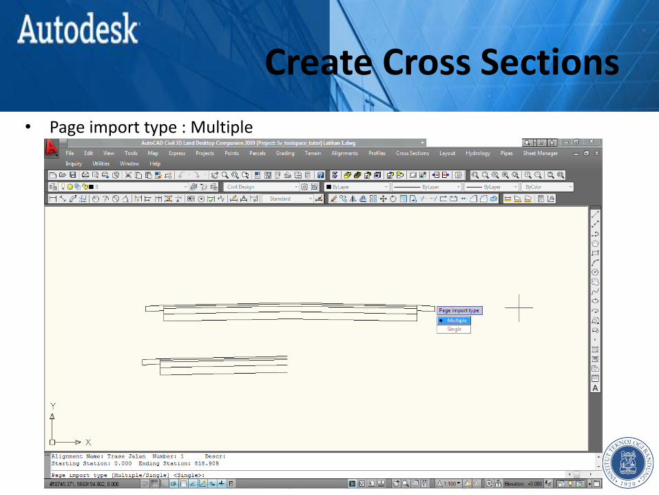
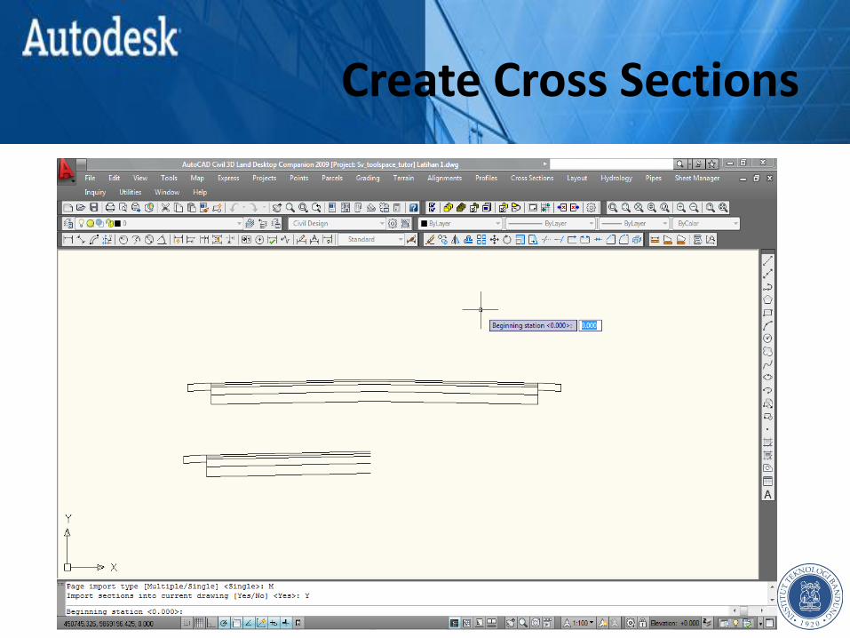
• Page import type : Multiple

Create Cross Sections
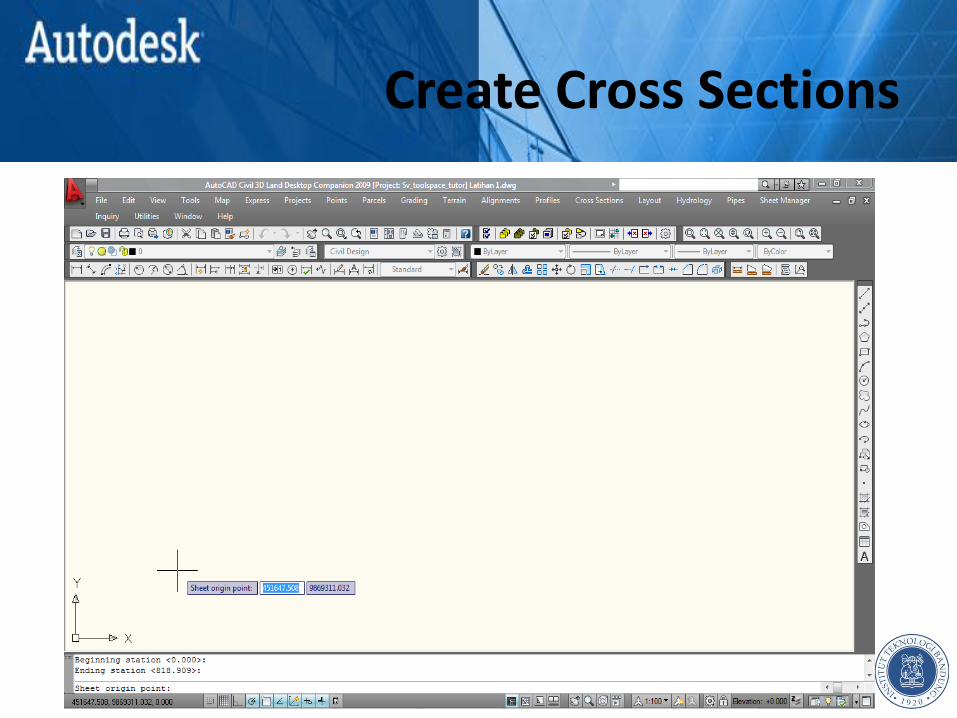
• Import section into current drawing : Yes
Create Cross Sections

Create Cross Sections
Create Cross Sections
Create Cross Sections

Create Cross Sections
CREATE VOLUME TABLE Chapter 7

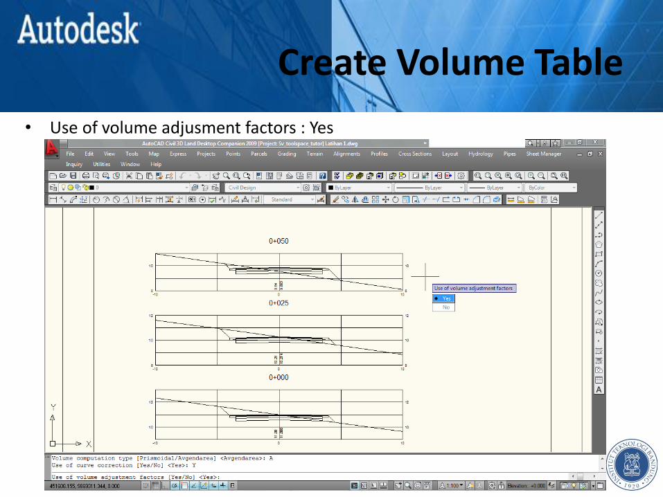
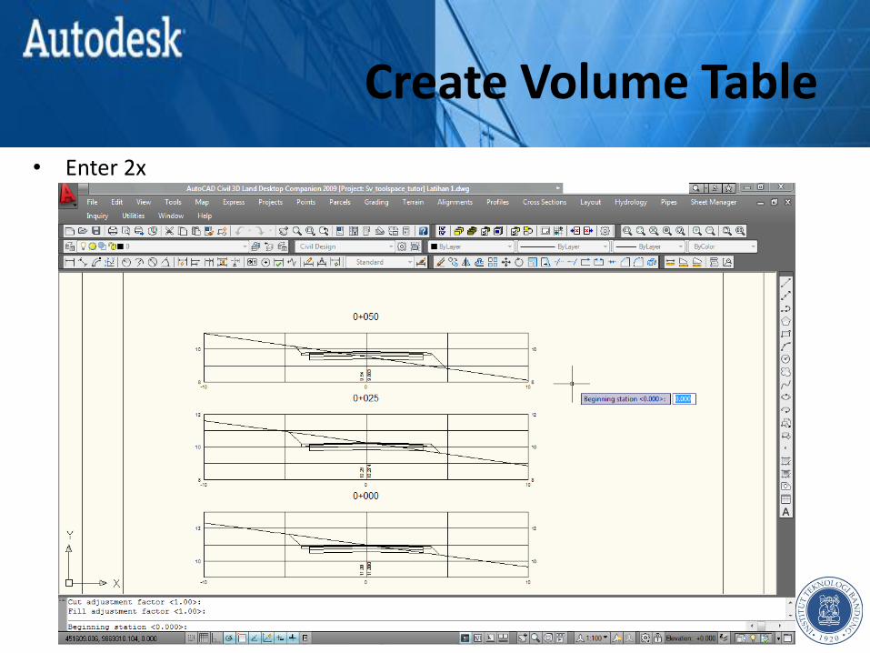
Create Volume Table
• Cross Sections Total Volume Output Volume Table

Create Volume Table
• Volume computation type : Avgendarea

Create Volume Table
• Use of curve correction : Yes
Create Volume Table
• Use of volume adjusment factors : Yes

Create Volume Table
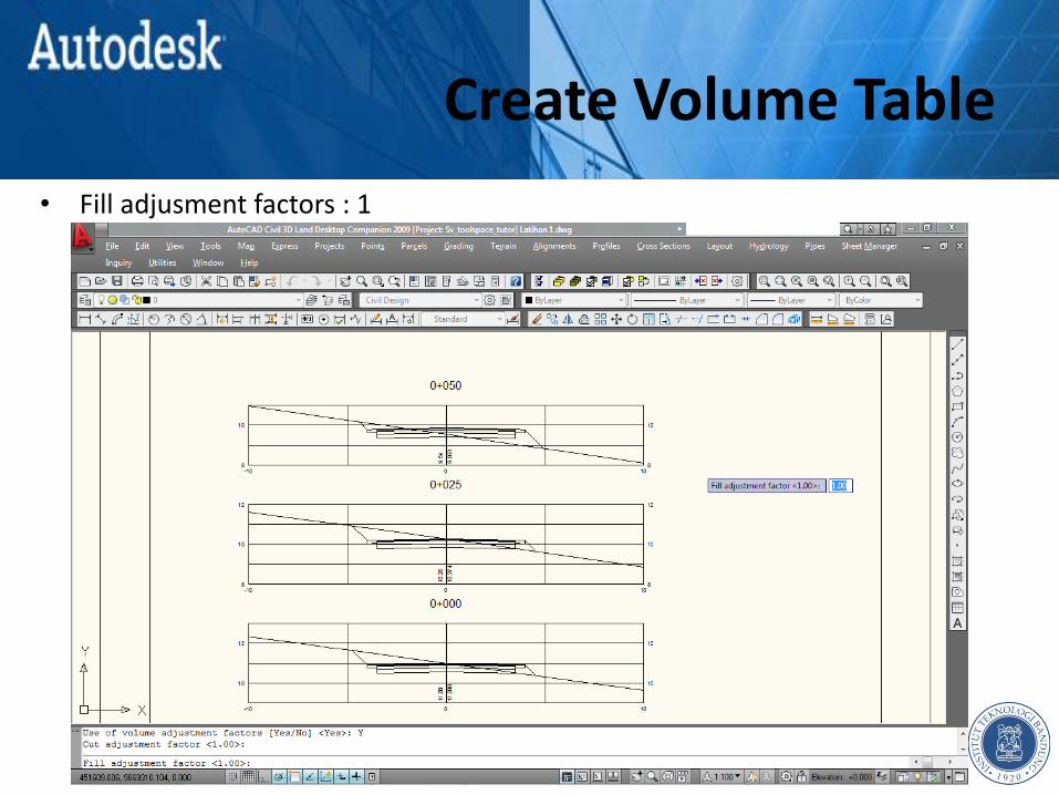
• Cut adjusment factors : 1
Create Volume Table
• Fill adjusment factors : 1
Create Volume Table
• Enter 2x
Create Volume Table
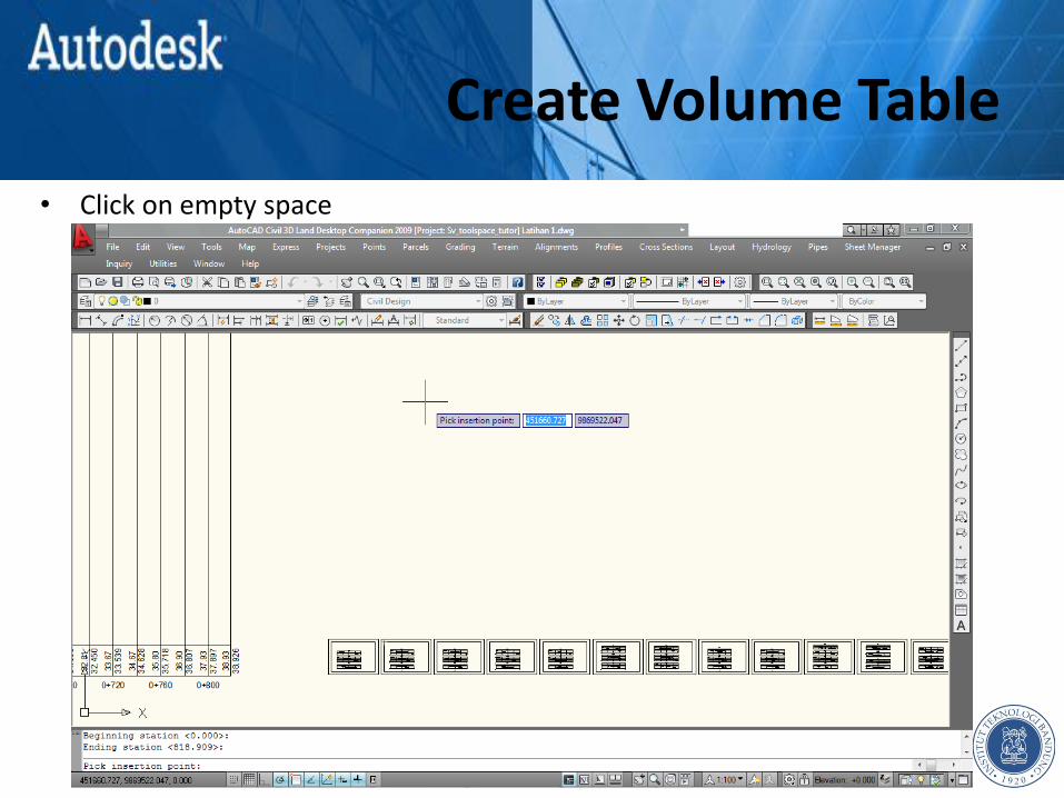
• Click on empty space

Create Volume Table
Create Volume Table
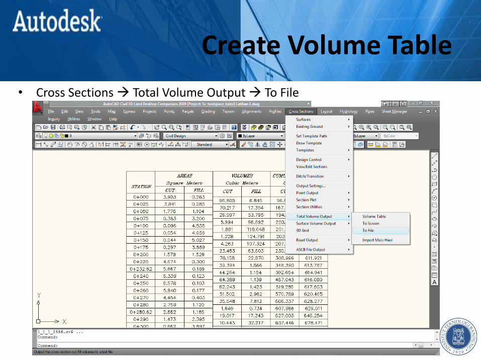
• Cross Sections Total Volume Output To File
Create Volume Table
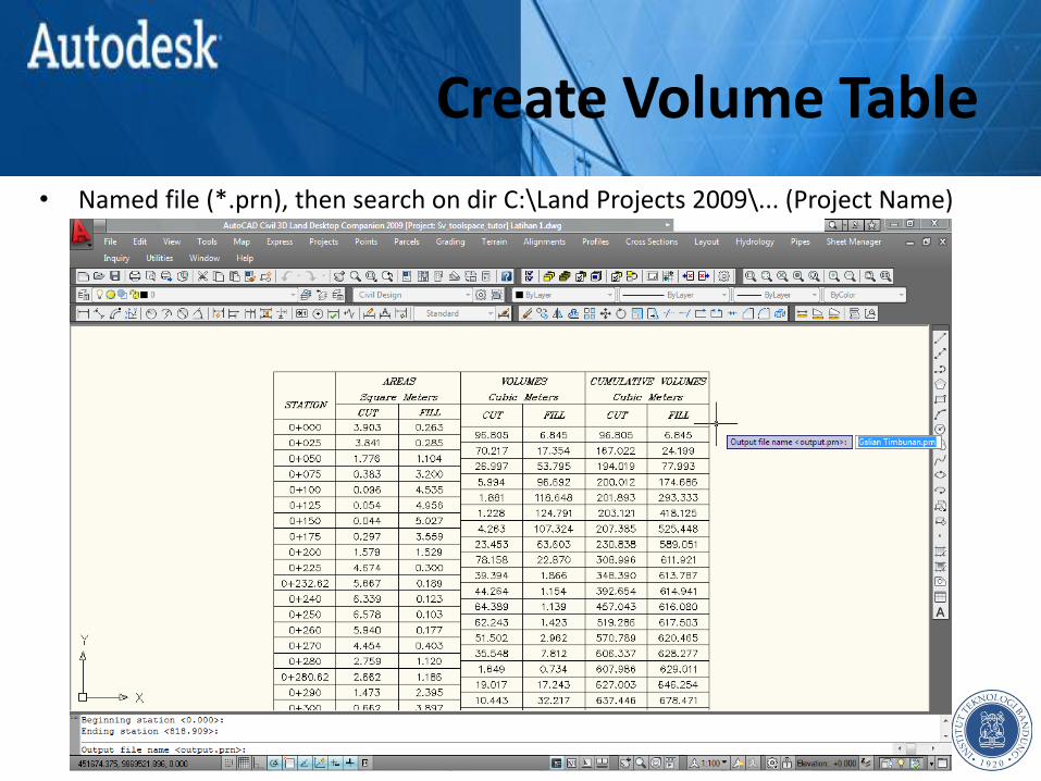
• Named file (*.prn), then search on dir C:\Land Projects 2009\... (Project Name)

Create Volume Table
• Output file (*.prn)
SOLVE A PROBLEM “SURFACE LOCKED”
Chapter 8
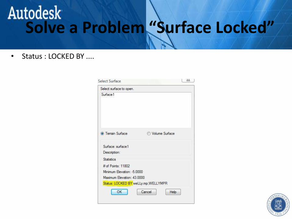
Solve a Problem “Surface Locked”
• Status : LOCKED BY ....

Solve a Problem “Surface Locked”
• Terrain Terrain Model Explorer
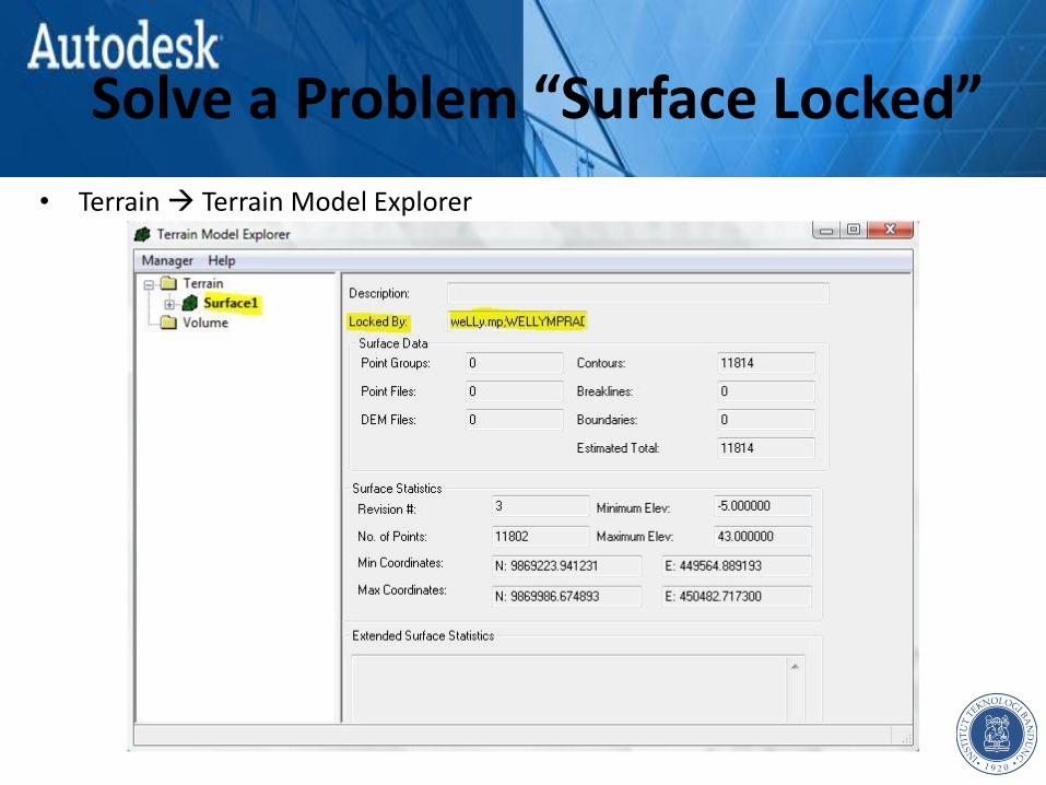
Solve a Problem “Surface Locked”
• Terrain Terrain Model Explorer

Solve a Problem “Surface Locked”
• Surface1 (right click) Build
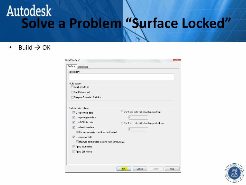
Solve a Problem “Surface Locked”
• Build OK
Solve a Problem “Surface Locked”
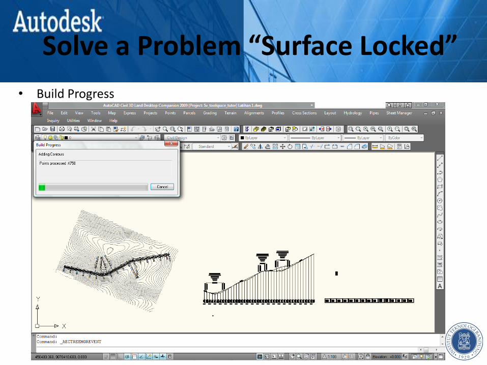
• Build Progress
Solve a Problem “Surface Locked”
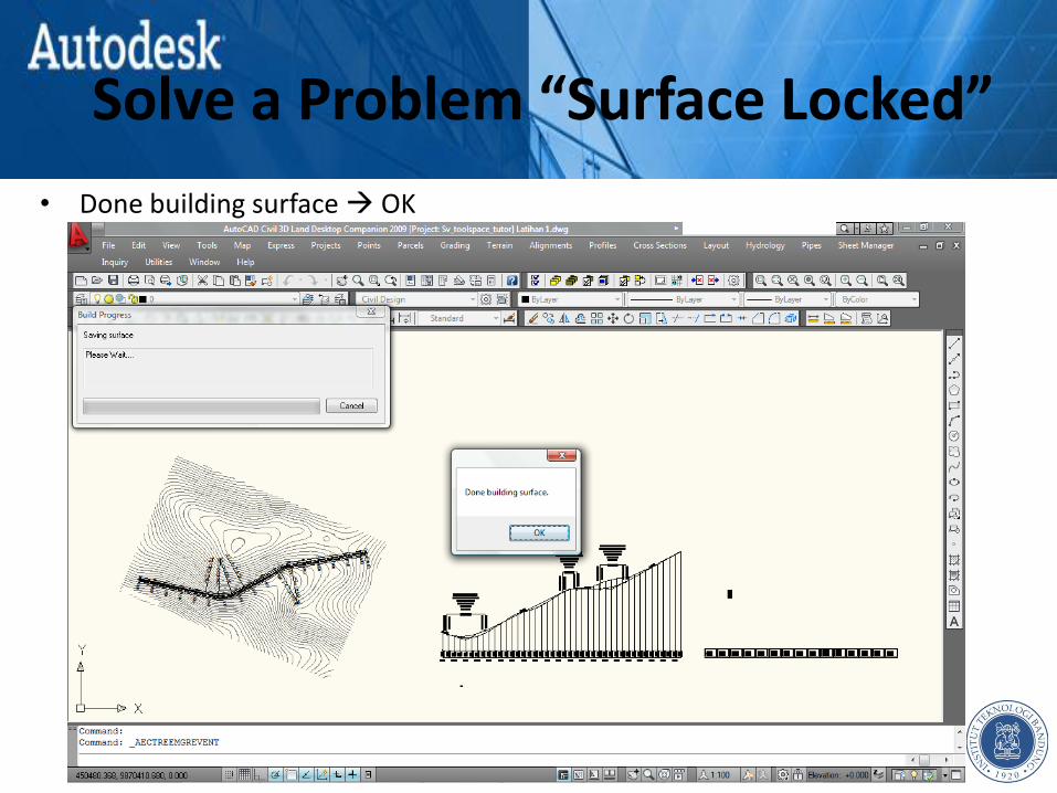
• Done building surface OK

Solve a Problem “Surface Locked”
• Surface1 (right click) Close
Solve a Problem “Surface Locked”
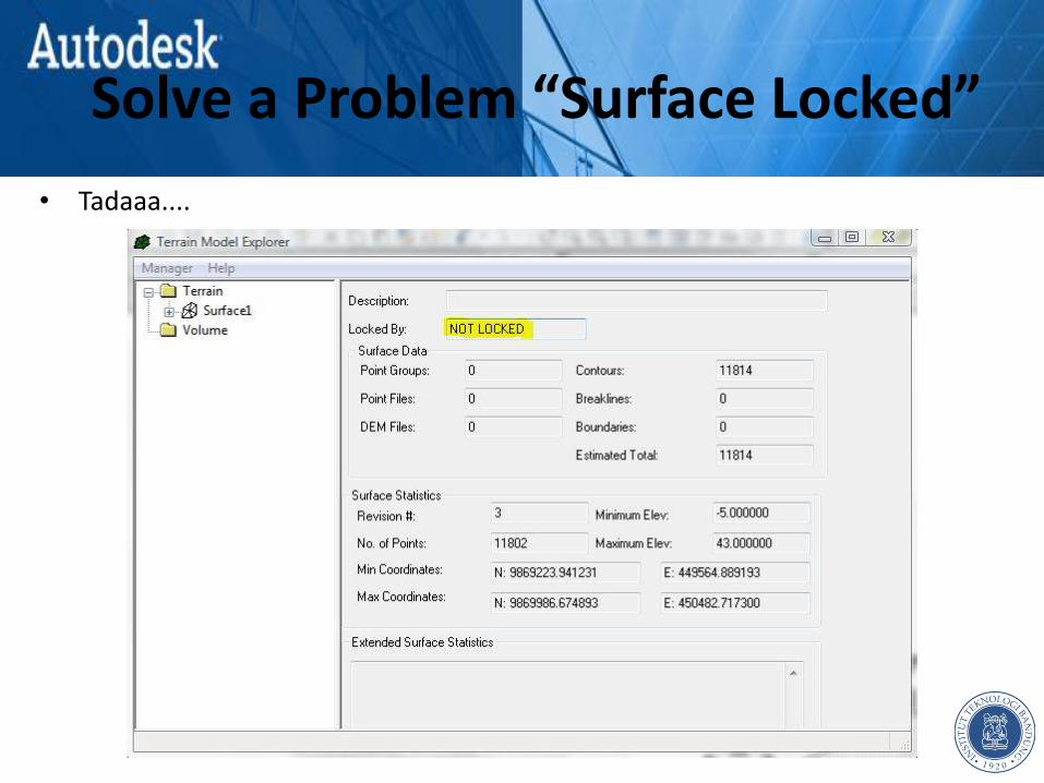
• Tadaaa....

CREDIT Chapter 9
Credit
Thanks to :
• Gugun Guntara, ST., MT.
• Guntur Bayuta, ST.
• Rizko Pradana Andika, SST.
• Students of Master Highway Engineering and Development (STJR) 2010
Contact Person :
f : welly bin maryulis
t : @wpradipta