Embed Size (px)
Citation preview

Basic Concepts of Ventilation Design
Building Design and Engineering Building Design and Engineering Approaches to Airborne Infection ControlApproaches to Airborne Infection Control
Jack Price

General Principles of Ventilation
Introduction
Need for ventilation:
ComfortContamination Control
both maintain healthy work environment

General Principles of Ventilation
• Office buildings ----- In-door air quality
• Occupational exposure ---- OSHA
• Environmental releases ---- EPA

General Principles of Ventilation
• Regulatory Agencies (compliance concerns)• Federal• State• Local
• Good Practice• Standard of care (industry standards ANSI, ASME, etc.)
• Work productivity• Process control

Types of Systems
• Supply
• Exhaust
Temperature & Humidity
Replacement (make-up air)
Return (recirculated air)
General (dilution)
Local Control (hoods)

HVAC Systems
Air Balance in a Conditioned Space
Air Handling System with Economizer


Design Concerns
• Temperature• Pressure• Air Contaminants• Work Practices• Product Protection• Worker Protection• Building Codes
• Equipment Selection• Energy Conservation• Maintenance• Security• Expansion

Patient Isolation Room with HEPA Exhaust Filtration

Air Conditioning System Water and Refrigeration Circuits

Factors in the Perception of Air Quality
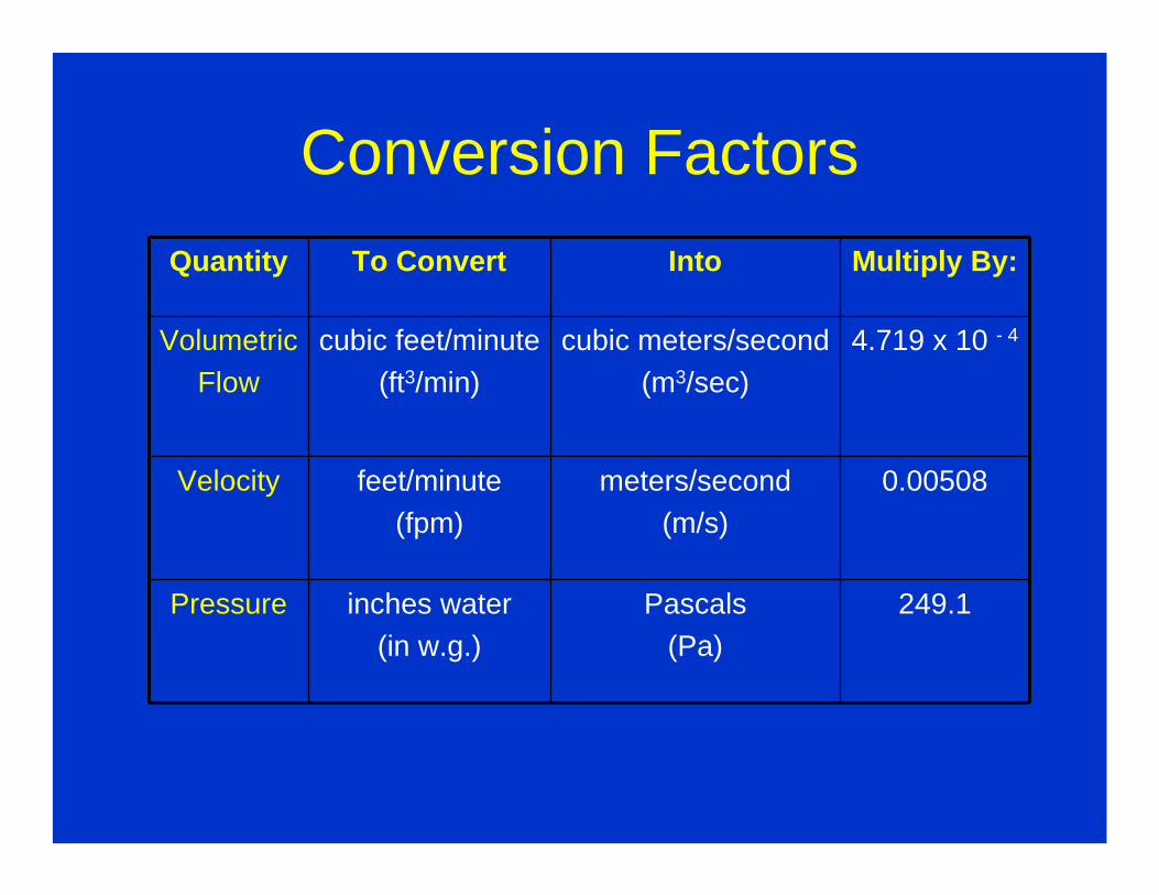
Conversion FactorsQuantity To Convert Into Multiply By:
VolumetricFlow
cubic feet/minute(ft3/min)
cubic meters/second(m3/sec)
4.719 x 10 - 4
Velocity feet/minute(fpm)
meters/second(m/s)
0.00508
Pressure inches water(in w.g.)
Pascals(Pa)
249.1

Conservation of Mass
Q = V . AWhere Q = Volumetric Flow Rate, ft3/min
V = Air Velocity, ft/min or fpmA = Cross Sectional Area, ft2 or SF
1 velocity = 50 FPM
Air Flow
2 velocity = 3000 fpmHood
Duct
Flow rate at point 1 is called Q1
and is equal to
flow rate at point 2 which is called Q2

Conservation of Mass
Q = V . A
1
2
3
Q1 + Q2 = Q3
V1A1 + V2A2 = V3A3
8 inch duct12 inch duct
6 inch duct

AIR FLOW
• At standard temperature and pressure (STP):* 1 atmosphere & 70o F *
The density of air is 0.075 lbm/ft3
• Air will flow from a higher pressure region to a lower pressure region
• Three Different Types of Pressure Measurements* Static * Velocity * Total *

Types of Pressure Measurements
• Static Pressure (SP)potential energy bursting or collapsingcan be + or – measured perpendicular to flow
• Velocity Pressure (VP)kinetic energy accelerates from 0 to some velocityExerted in direction of flow always +
• Total Pressure (TP)combined static & velocity components measure of energy content of air streamcan be + or - Always decreasing as flow travels
downstream thru a system only rising when going across a fan

TP_+
SP_+
VP +
TP = SP + VP

Conservation of Energy• TP = SP + VP or TP = SP + VP
• Energy losses:– Acceleration of air – Hood entry – Duct losses: friction (function of system materials & design)– Fitting losses: contractions & expansions
• TP1 = TP2 + hL now substitute TP = SP + VP
• SP1 + VP1 = SP2 + VP2 + hL

Pressure Graphs for TP, SP, and VP
Bench Grinder
Hood

Velocity Pressure & Velocity• V = 1096 (VP/p)0.5 where p = air density
@ STP p = 0.075 lbm/ft3
• V = 4005 (VP)0.5
• Velocity pressure is a function of the velocity and fluid density.
• Velocity pressure will only be exerted in the direction of air flow and is always positive.

Bench Grinder Exhaust Ventilation
• Q1 = Q2
• If Q desired is 300 cfm• Then Q = V A
V = Q AV = (300) / (0.0068)V = 4490 fpm
• If there are no losses from the grinder hood entry then:
SP1 + VP1 = SP2 + VP2
but: SP1 = 0 and VP1 0
we then have:
0 = SP2 + VP2or -VP2 = SP2
1 Duct diameter = 3 inches
Area = 0.0668 ft2
2 3

Bench Grinder Exhaust Ventilation
• from V = 4005 (VP)0.5
• VP2 = (4490/4005)2
• VP2 = 1.26 in w.g.
• then: SP2 = (-VP2 )
SP2 = -1.26 in w.g.
• If there are no losses from the grinder hood entry then:
SP1 + VP1 = SP2 + VP2
but: SP1 = 0 and VP1 0
we then have:
0 = SP2 + VP2or SP2 = (-VP2 )
1 Duct diameter = 3 inches
Area = 0.0668 ft2
2 3
V = 4490 fpm

Bench Grinder Exhaust Ventilation
• However there are losses thru the grinder hood entrySP2 = - (VP2 + he ) where he is the energy loss of the hood entry
• Static pressure (SP) must decrease due to acceleration of air up to the duct velocity
• Fh is defined as the energy loss factor (for that hood design)
• Energy losses will be measured as a function of the velocity pressure in the systemhe = (Fh ) (VP)
• Now we define the static pressure at the hood as SPh
• SPh is also called the hood static suction and is the absolute value of SP2
1 Duct diameter = 3 inches
Area = 0.0668 ft2
2 3
V = 4490 fpm
SPh

Bench Grinder Exhaust Ventilation
• Now add the hood entry loss:
SPh = VP2 + he = VP2 + (Fh ) (VP2)
Assume that the hood energy loss factor for this hood is 0.40
• SPh = 1.26 + (0.40) (1.26) = 1.76 in w.g.
1 Duct diameter = 3 inches
Area = 0.0668 ft2
2 3
V = 4490 fpm
SPh

Flanged Inlet with Fd = 0.49

Flanged Inlet with Fd = 0.49
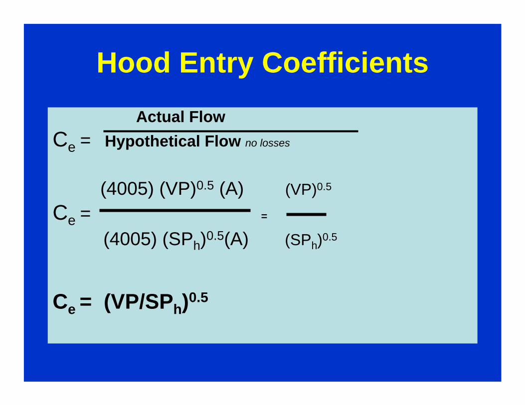
Hood Entry CoefficientsActual Flow
Ce = Hypothetical Flow no losses
(4005) (VP)0.5 (A) (VP)0.5
Ce = =
(4005) (SPh)0.5(A) (SPh)0.5
Ce = (VP/SPh)0.5

Hood Entry Coefficients
Ce = (VP/SPh)0.5
Typical values for Ce are known for some hoods.
For the bench grinder hood with a straight take-off : Ce = 0.78

Example Problem
• What static pressure (SPh) should be set at the bench grinder hood to maintain a duct velocity of 4000 fpm if the take-off duct size is 4 inch diameter ?
• What is the volumetric flow rate ?

Example Problem• V = 4000 fpm Q = VA = 4005(A)(VP)0.5 Q = VA = 348 cfm• A for 4 inch duct diameter = 0.087 ft2
• Ce bench grinder hood = 0.78
Ce = (VP/SPh)0.5 = 0.78
(VP/SPh) = (0.78)2
SPh = VP/(0.78)2 = (0.998)/(0.608) = 1.64 in w.g.
V = 4005 (VP)0.5
(VP)0.5 = (4000)/(4005)
VP = 0.998 in w.g.
1.64 in w.g.

Air Flow Characteristics
• See Industrial Ventilation Manual notes
Blowing vs. Exhausting

Air Flow Characteristics
Exhaust Hoods
Capture Velocity
From Dalla Valle’s empirical work
V(x) = Q/ (10 x2 + A)

Capture Velocity
V(x) = Q/ (10 X2 + A)
Capture velocity is only effective in the immediate vicinity of the hood
Room supply air (make-up air) discharge can influence effectiveness of hood capture

Questions ?

Ventilation Systems: Operation and Testing
InIn--Place Filter Testing WorkshopPlace Filter Testing Workshop

HVAC Systems

HVAC Systems
Air Balance in a Conditioned Space
Air Handling System with Economizer


Questions ?