Embed Size (px)
Citation preview
2013 Spec Revision K –05/01/17
DETACHED & ATTACHED
TWO & THREE STOREY
TIMBER FRAME HOUSES
BARRATT NORTH SCOTLAND
SPECIFICATION
CALEDONIA & ALBA RANGE
2013 TECHNICAL STANDARDS

2
REVISIONS INDEX
BNS 2013 Timber Frame Spec based on BWS 2010 Spec Revision G above: Revision A 15/07/14 Specification updated to say “2013 Standards” in lieu of 2010 Revision B 02/09/14 Specification update to Sound Insulated Partitions Revision C 16/10/14 Specification update to Sound Insulated Partitions & External Walls Revision D 06/11/14 Specification update to Sound Insulated Partitions next to Bathrooms &\or En-suites Revision E 10/12/14 Specification update for Carbon Monoxide Detectors Revision F 27/03/15 Specification update for garage ceiling for garage ceiling Revision G 08/07/15 Specification updated for new insulation. Revision H Specification for Single Leaf Apex Panel – Withdrawn. Revision J 21/04/16 Specification updated for revised thermal spec. Revision K 05/01/17 Specification of Scarcement Edge Insulation and Plasterboard finish updated
1
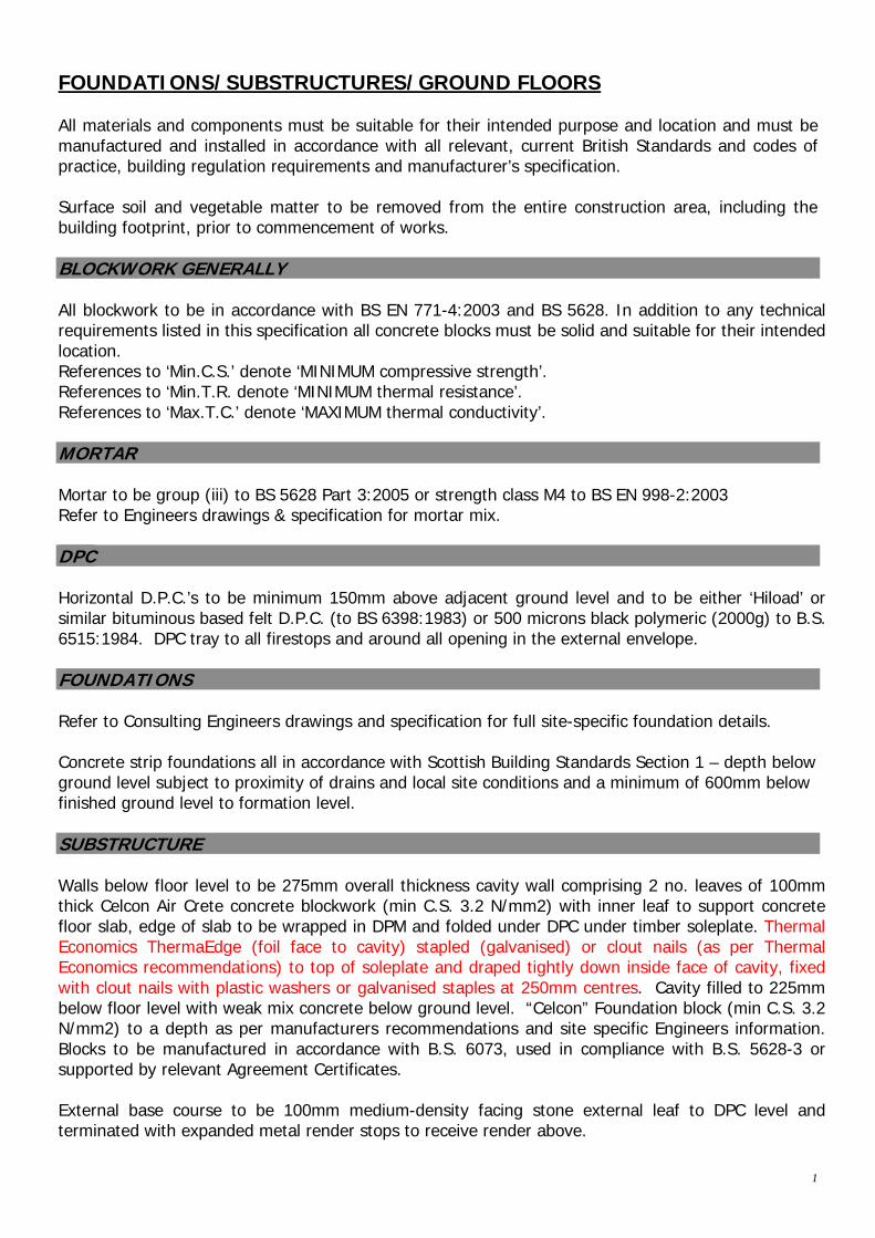
FOUNDATIONS/SUBSTRUCTURES/GROUND FLOORS All materials and components must be suitable for their intended purpose and location and must be manufactured and installed in accordance with all relevant, current British Standards and codes of practice, building regulation requirements and manufacturer’s specification. Surface soil and vegetable matter to be removed from the entire construction area, including the building footprint, prior to commencement of works. BLOCKWORK GENERALLY All blockwork to be in accordance with BS EN 771-4:2003 and BS 5628. In addition to any technical requirements listed in this specification all concrete blocks must be solid and suitable for their intended location. References to ‘Min.C.S.’ denote ‘MINIMUM compressive strength’. References to ‘Min.T.R. denote ‘MINIMUM thermal resistance’. References to ‘Max.T.C.’ denote ‘MAXIMUM thermal conductivity’. MORTAR Mortar to be group (iii) to BS 5628 Part 3:2005 or strength class M4 to BS EN 998-2:2003 Refer to Engineers drawings & specification for mortar mix. DPC Horizontal D.P.C.’s to be minimum 150mm above adjacent ground level and to be either ‘Hiload’ or similar bituminous based felt D.P.C. (to BS 6398:1983) or 500 microns black polymeric (2000g) to B.S. 6515:1984. DPC tray to all firestops and around all opening in the external envelope. FOUNDATIONS Refer to Consulting Engineers drawings and specification for full site-specific foundation details. Concrete strip foundations all in accordance with Scottish Building Standards Section 1 – depth below ground level subject to proximity of drains and local site conditions and a minimum of 600mm below finished ground level to formation level. SUBSTRUCTURE Walls below floor level to be 275mm overall thickness cavity wall comprising 2 no. leaves of 100mm thick Celcon Air Crete concrete blockwork (min C.S. 3.2 N/mm2) with inner leaf to support concrete floor slab, edge of slab to be wrapped in DPM and folded under DPC under timber soleplate. Thermal Economics ThermaEdge (foil face to cavity) stapled (galvanised) or clout nails (as per Thermal Economics recommendations) to top of soleplate and draped tightly down inside face of cavity, fixed with clout nails with plastic washers or galvanised staples at 250mm centres. Cavity filled to 225mm below floor level with weak mix concrete below ground level. “Celcon” Foundation block (min C.S. 3.2 N/mm2) to a depth as per manufacturers recommendations and site specific Engineers information. Blocks to be manufactured in accordance with B.S. 6073, used in compliance with B.S. 5628-3 or supported by relevant Agreement Certificates. External base course to be 100mm medium-density facing stone external leaf to DPC level and terminated with expanded metal render stops to receive render above.
2
INSULATED DWELLING GROUND FLOORS Refer to house type specific SAP for u value Refer to Engineers drawings and specification for details of fully suspended ground floor slabs. Overall floor build up consists of power floated concrete slab, to engineer’s details on 1200 gauge DPM over Thermal Economics Platinum Ground Floor Insulation. (REFER TO APPENDIX A&B FOR HOUSE TYPE SPECIFIC INSULATION THICKNESS) All DPM joints to be sealed and lapped MIN 300mm dressed under wall DPC. Insulation laid on 25mm sand blinding on 150mm well compacted sulphate free hardcore. Where gas protection measures are required refer to Architects and Engineers site specific details showing gas membranes, all in compliance with BRE and NHBC Guidelines. U-Value of 0.10 W/m2K GARAGE FLOORS Concrete in-situ slab as described above but without the inclusion of insulation, subject to site conditions dictating otherwise. Integral garage floor slabs to be laid 100mm lower than main dwelling slab with 50mm fall towards front door.
EXTERNAL WALLS: SINGLE, 2 & 3 STOREY DWELLINGS All external timber to be pressure-impregnated with preservative prior to delivery to site. Structural timber to be to BS 5268: Part 2: 2002. EXTERNAL WALL CONSTRUCTION Max U-value of 0.25 W/m²K. External render coating on 100mm medium-density block external leaf (Min.C.S. 7.0 N/mm, Min. T.R. 0.333 m2K/W, Max density 1400Kg/m³), 50mm cavity fire stopped at all corners, junctions and external opening. Proctor Reflectashield TF 0.81 factory fitted to 9mm OSB BBA sheathing fixed to 38x140mm C16 CLS framing at 600mm centres. 140mm mineral wool insulation (REFER TO APPENDIX A&B FOR HOUSE TYPE SPECIFIC K Value) friction fitted on site and frame finished with 12.5mm duplex vapour check taper edged plasterboard with joints taped, filled and prepared for decoration. Pre-bent stainless steel wall ties (minimum 4.4 per square meter) at 600mm centres horizontally and 450mm centres vertically and at 225mm centres at door external opening jambs. On single and 2 storey dwellings, wall ties to be 2.8mm thick. On 3 storey dwellings, wall ties to be 4mm thickness. Slim line cavity vents to be provided at 900mm ctrs as follows: 1) Above dpc level, 2) Below ground floor ceiling firestop, 3) Above first floor, 4) Below first floor ceiling, 5) Gable apex below soffits and above header binder. INTEGRAL GARAGE WALL CONSTRUCTION (Insulated) Max U-Value of 0.25 W/m²K
3
From internal face, 12.5mm Gyproc WallBoard Duplex with vapour control layer, 9mm OSB BBA sheathing fixed to 38x140mm C16 CLS framing at 600mm centres. 140mm wool insulation (K Value 0.040) friction fitted on site with 38mm Gyproc Thermaline PIR insulated plasterboard sides plasterboard with joints taped, filled and prepared for decoration. No services to penetrate the above wall. Where services are shown on plan on house side additional framing of 25x50mm battens and 12.5mm plasterboard to be fitted and on garage side of separating partition these will have surface mounted wiring and boxes. INTEGRAL GARAGE WALL EXTERNAL CONSTRUCTION ( Non insulated) External render coating on 100mm medium-density block external leaf (Min.C.S. 7.0 N/mm, Max density 1400Kg/m³), 50mm cavity fire stopped at all corners, junctions and external opening. Breather membrane factory fitted to 9mm OSB BBA sheathing fixed to 38x89mm C16 CLS framing at 600mm centres. External walls frame finished with 12.5mm Gyproc WallBoard TEN taper edged plasterboard with joints taped and filled in prepared for decoration.
NOTE: Insulation is NOT required within external walls panels around garages. PARTY WALL CONSTRUCTION U-Value of 0.00 W/m²K Two separating wall timber frame leaves formed with 9mm OSB BBA sheathing fixed to 38x89mm C16 CLS framing at 600mm centres with a 50mm cavity between frames. Cavity full fill insulated by timber frame manufacturer with Superglass TF Party Wall Roll and 50x300mm insulated cavity barrier to edges of party wall cavity. Timber frame finished with 19mm Gyproc Plank laid horizontally and 12.5mm taper edged plasterboard with joints taped, filled and prepared for decoration. Moisture resistant plasterboard to be utilised in wet areas. No services to penetrate the above wall. Additional framing of 25x50mm battens and 12.5mm plasterboard to be fitted where required to conceal services. All to achieve 60 minute (Medium Duration) fire resistance. All party walls including separating walls between garages to be taken up to underside of roof line and fire-stopped using 2 no. layers mineral wool with first layer packed tight between battens to underside of roof tiles and second layer packed tight between wall head and roofing felt. Separating walls to achieve minimum airborne sound insulation level of 56dB DnT,w and a maximum impact sound transmission of 56dB L'nT,w. Close external abutting cavity with Isover cavity closer to prevent flanking transmission. DPC to be located at floor level in line with DPC in external walls and continuous with DPM. NOTE - SOUND TESTS TO BE CARRIED OUT UPON COMPLETION. MOVEMENT JOINTS Movement joints to be formed vertically at locations as described below. Unless otherwise stated, movement joints shown on house type drawings are for non-staggered terraces of up to 4 units. Notwithstanding any such locations, the location and width of movement joints in all external masonry panels (including freestanding external boundary walls) should be assessed having regard to the geometry of each particular terrace or wall configuration in accordance with BS 5628-5:1985 and block manufacturer’s recommendations. Joints in external leaf to be filled with cellular polyethylene or foam rubber and sealed with two-part polysulphide sealant to match colour of render coating as closely as possible. Wherever possible, joints should be located behind rainwater pipes. Additional wall ties to be installed in the cavity wall max 225mm to each side of the joint at 225mm vertical centres in

4
accordance with BS EN 846-5:2000 and – in Sovereign Range only – proprietary flat-strip debonded ties to be installed across joint at 450mm vertical centres. LINTOLS Lintols to be provided over all structural openings including meter boxes in accordance with drawings and lintol schedules. Lintol references are generally those of I.G. Lintols Ltd. and denote pressed steel type lintols designed in accordance with BS 5977:1981, galvanised to BS 729:2001. Any alternatives must be approved and satisfy all the above requirements. Where IG references are not given the lintols are to be as detailed in Structural Engineer’s calculations. All lintols must bear on full (NOT CUT) blocks. Cavity trays / damp proof protection must be provided over all external openings either separately or as a combined part of the lintol to satisfaction of Local Authority. Minimum 2 no. weep holes per opening to be provided spaced at maximum 450 intervals. Adequate end bearings of 150mm minimum must be provided (any reduction must be to satisfaction of Structural Engineer) and lintol to be firmly bedded in mortar. Pad stones to be provided in accordance with Structural Engineer’s Design where necessary. Manufacturer’s recommendations for providing adequate fire resistance should be followed. Cold bridge paths should be avoided and adequate insulation measures incorporated, depending upon lintol profile, in accordance with manufacturer’s specification. All steelwork to be zinc coated and painted with bitumen. STEELWORK Steelwork to be fitted as per drawings to structural engineers requirements. All steelwork to have a minimum of 150mm bearing at each end on suitable concrete pad stone to engineers recommendations. CAVITY TRAYS & FLASHINGS All flashings to be in milled lead sheet to BS 1178:1982. Code 4 lead flashings (stepped where necessary) to be provided where roofs abut blockwork. All flashings to be dressed up wall min. 150mm above surface of tile. Cavity trays to be linked to flashings in all cases and stepped in the case of a stepped flashing. Cavity trays must rise minimum 75mm across cavity. Code 4 lead soakers to be provided at each tile overlapped by flashings. Valleys to be lined with Code 5 lead. INTERNAL STANDARD NON-LOAD BEARING AND LOAD BEARING PARTITIONS/FLOORS/DOORS /STAIRS LOAD BEARING Where partition is loadbearing minimum 89mm x 38mm C16 stud partitions with studs at 600mm c/c and mid row dwangs with 1 No. layer 12.5mm Gyproc Wallboard 10 plasterboard taped & filled to both sides. Horizontal D.P.C. to be located below all ground floor partitions. NON- LOAD BEARING Where partition is non-loadbearing minimum 75mm x 38mm s.w stud partitions with studs at 600mm c/c and mid row dwangs with 1 No. layer 12.5mm Gyproc Wallboard 10 plasterboard taped & filled to both sides. Horizontal D.P.C. to be located below all ground floor partitions.
PROTECTED ENCLOSURE PARTITIONS (3 STOREY ONLY)
5
Protected enclosure separating partitions to be ‘short duration’ fire resistance & constructed of either 89mmx38mm CLS C16 sw stud partitions or 38 x 75mm s.w. stud partitions at 600mm c/c and mid row with 15mm Gyproc Wallboard taped & filled to both sides.
1) 15mm Gyproc Moisture Resistant plasterboard to Bathroom &\or En-suite wet areas only i.e. around showers/baths side with both sides taped & filled joints.
2) Where such partitions separate a room containing a W.C. from a Living Room, Dining Room,
Study or Bedroom 25mm min. thickness acoustic insulation quilt to be installed between the studs.
3) Separating partitions between apartment and bedroom from circulation space or each other to have minimum 25mm thick acoustic insulation quilt to be laid between the studs.
To achieve minimum 43dB Rw to satisfy Section 5 of 2013 Scottish Building Standards. All Studs to be fixed to G.F. slab (where applicable) with 100mm long Hilti HUS anchors at 400mm c/c and fixed to external cavity walling using Hilti HT frame anchors HT10/112 at 400mm c/c vertically. Horizontal d.p.c to be located below all ground floor partitions. FIRE RESISTANT DOORS Any doors linking accommodation to garages to be fire resistant grade FD30s and contained within frames incorporating cold smoke seals providing “short duration” fire resistance. All doors within protected stairwell/hallways in 3 storey dwellings to be FD30s rated. This includes all store, WC, bedroom, kitchen, living room, dining room doors accessed off the protected enclosure. Bathroom doors do not require to be fire rated, provided the FD30 stair enclosure is extended to contain bathroom, with no openings. With exception of store doors, all doors to be fitted with self-closing device. Rising butt hinges are not acceptable. Door closers to be sized to suit the door leaf they are fitted to, and must be capable of closing the door into the latched position, taking account of the smoke seals. UPPER FLOORS Finnforest Finn joist proprietary timber I-Beams and Finnforest Kerto proprietary laminated ply beams are to be used in all cases for upper floors. The joist layouts prepared by the manufacturers must be adhered to in terms of setting out to ensure structural stability in all cases. Finnforest products must be stored, handled and installed strictly in accordance with manufacturer’s recommendations. I-Beams are unstable until laterally braced and particular attention is drawn to the manufacturer’s recommendations for the installation of temporary diagonal and longitudinal bracing and temporary stability blocking. I-beams and laminated ply beams will generally be 220mm deep, fixed at (and not exceeding) 600mm centres. All such floors to be finished with 22mm thick Caberdeck or equivalent flooring grade moisture resistant T&G Type C chipboard to B.S.5669. Flooring to be fixed with 65mm x 3.35mm angular ring shank nails at 200m around the perimeter and at 300mm centres intermediately. Flooring to be glued with PVA adhesive between boards and joists. Trimming to be provided where necessary to allow for stair case openings, horizontal waste/soil pipes and s.v.p.'s all in accordance with plans prepared by Finnforest or their representatives.

6
Min. 38 x 38mm noggings to be fixed with proprietary 'Z clips' to top flanges of I-Beams around all perimeters for fixing edges of floor decking. Stud partitions parallel to the floor span but not located immediately over I-Beams to be supported on min. 35 x 72mm noggings at max. 600mm ctrs. between joists - noggings to be fixed to top flange of beams using proprietary 'Z clip' hangers. Where Finnforest layout features I-Beams supported on hangers off I-Beam trimmers or headers, min. 250mm wide solid timber backer blocks must be located each side of the supporting beam web, tight up to the beam top flanges for top mount hangers and to the bottom flange for face mount hangers attached with 12No total 3.75 x 75mm nails fitted from hanger face. Where shown on Finnforest layout, min. 100mm wide web stiffeners to be fitted each side of the I-beam web and attached with 3No total 3.35 x 75mm nails clenched from each side - care must be taken to ensure that a 5-20mm gap is left between the stiffener block and either the top timber flange if at an end-bearing or the bottom timber flange at a top load application. Widths and heights of Backer Blocks and Web Stiffeners are specific to I-beam depth and series - refer to Finnforest Floor System brochure Backer Block & Web Stiffener table. Where the I-Beam trimmers or headers are doubled-up, 600mm long Filler Blocks must be fitted between the adjacent beam webs at each supported hanger location, tight up to the beam top flanges and attached with 3.75 x 75mm nails installed from the hanger face and clenched (4.00 x 90mm nails if attached to Finnforest FJI 89 series beams). Widths and heights of Filler Blocks and number of nails required for fixing are specific to I-beam depth and series - refer to Finnforest Floor System brochure Filler Block table. Unless otherwise stated, where hot water cylinders are located over stair bulkheads, support framing to be 97 x 38mm C16 s.w. at max 400mm ctrs. Notching & Drilling. Timber I-Beams may have circular or rectangular holes carefully formed within the webs but only strictly in accordance with the I-Beam manufacturer’s published diagrams, tables and general cutting criteria - the size and spacing of such holes and their location with respect to the end of the beam is absolutely critical. Under no circumstances should the top or bottom I-beam flanges be notched or drilled. Laminated ply beams may only be notched and drilled within the limits shown on the following detail. Notches and drillings in laminated ply beams to be at least 100mm apart horizontally. Special instructions should be obtained from the Structural Engineer when notching and drilling does not meet the above guidelines or is needed close to heavy loads, such as those from partitions, cisterns, cylinders and stair trimming. If structural strength is impaired by notching or drilling, the element should be replaced or correctly repaired (to Finnforest recommendations or remedial detail in the case of a damaged I-beam). 2-Storey Dwellings. Where floor void is above integral Garage, void to be fully filled with 220mm mineral fibre thermal insulation (K Value 0.038) is to be installed in the floor void and 15mm Gyproc Wallboard ceiling to achieve a U Value of 0.17 W/m2K. Where ground floor plan features a store located below straight-flight staircase, stair soffit to be lined with 1 layer 15mm Gyproc Wallboard.
7
Where store occurs below winder staircase, 60mm mineral wool to be pinned to underside of flight and soffit to be wet-plastered over expanded metal mesh formed to suit staircase profile. All intermediate floors within the dwelling must achieve a minimum of 43dB Rw airborne sound insulation. Comprised of 220mm deep I-beams and laminated ply beams fixed at (and not exceeding) 600mm centres with 22mm ‘Caberdeck’ chipboard flooring, 100mm thick mineral wool quilt (10kgm-3) laid between joists and 15mm 'Gyproc Wallboard' ceilings. Moisture resistant plasterboard to wet areas. All as per this Specification unless joist centres changed to specific house type where, in certain circumstances, joist centres may be closer. STAIRCASE Straight and tapered stair flights and landings to be formed strictly in accordance with current 2013 Scottish Building Regulations, section 4.3. Tapered goings: Equally sized, measured along center line of flight and not less than the straight goings. Private Stair Min tapered tread: 50mm 2xriser+going = 550 Min, 700 Max. goings: 225mm Min. risers: 220mm Max. pitch: 42° max pitch. Width: Min clear width 900mm with continuous handrail on 1 side. Min clear width 800mm with handrail fitted both sides (continuous handrail
on 1 side). Height: 2000mm clear above pitch line. ‘Any Other’ Stair Min tapered tread: 50mm 2xriser+going = 550 Min, 700 Max. Goings: 250mm Min. Risers: 170mm Max. Pitch: 34° max pitch. Width: Min clear width 900mm with continuous handrail on 1 side to single
dwelling. Height: 2000mm clear above pitch line. Timber handrails and balustrading to be provided between flights with newel posts at top and bottom of flights and at change in direction of tapered treads. Balustrading spaced to prevent the passage of 100 dia sphere. Handrail height measured 900mm above pitch line of stair. (Handrail height min 840mm, max 1000mm, measured vertically above pitch line of flight or landing surface) Where a handrail is provided to only 1 side of a private stair flight, the side on which a handrail is not fixed should permit installation of a second handrail at a future date. A second handrail will provide additional support to a person using the stair and may be installed provided a clear width of 800mm is maintained. Minimum landing length to be either 900mm with handrail on 1 side or 800mm with handrail fitted both sides. Protective barriers and handrails to have balustrade which will not permit the passage of a 100mm dia. sphere.
8
Newel posts to be provided, where required. Flights to consist of min 3 & max 16 risers. Ramps & Landings Gradient - 1:20 to not more than 1:12 max Flight length related to gradient e.g.
1:20 – 10m, 1:15 – 5m, 1:12 – 2m Width: 1.0m min effective width between any handrails/guard kerbs. Landings: to be provided top & bottom of every flight with effective width not less than that of
the flight. Landing length 1.5m min. Handrails to be fitted to both sides of ramp which has a flight longer than 2m or where change of level is more than 600mm. GLAZING All windows to be double glazed PVC with thermal inserts and warm edge spacers to achieve a U-value of 1.41 W/m²K and a G-value of 0.73 Window style to be in accordance with house type elevations and schedules. Obscured glazing to front door, bathroom, en suite and cloakroom windows, and also landing window if directly overlooking an adjacent window within 13 metres. In accordance with 2013 Scottish Building Standards Section 4.8 all glazing should be designed to resist collision from occupants in accordance with BS6262 part 4: 2005; all glazing below 1500mm above finished floor level in both doors and sidelights within 300mm of door jamb and all other areas of glazing below 800mm above finished floor level must be either:- a) toughened or laminated and break safely to BS 6206:1981, or b) robust i.e. 8mm annealed glass in panes not exceeding 1.1m in both height and width, or c) 6mm annealed glass in small panes, i.e. maximum width 250mm and area 0.5m2. All opening lights (and doors) to be fitted with draught proof strips. All upper floor opening lights of windows to be fitted with EASY-CLEAN hinges which comply with clauses 10.2, 10.3 and 10.4 of BS 8213 : Part 1:2004. All opening lights where the bottom of the window opening is less than 800mm above FFL, and also at ground floor level, where the difference between external ground and FFL exceeds 600mm, must be fitted with protective barriers in front of windows fixed 800mm AFFL. ALL outward opening windows over footpaths and opening lights at second floor to be fitted with suitable restrictors to prevent the opening of the window by more than 100mm - restrictors to be easily by-passed by an adult without use of tools and located out of reach of small children. EMERGENCY ESCAPE WINDOWS All habitable rooms (apartments) at first floor level must be provided with an escape window of a size to give an unobstructed opening that is at least 450mm high and 450mm wide and at least 0.33m2 in area. The openable area of the window should not be more than 1100mm above the finished floor level, in accordance with 2013 Scottish Building Standards Section 2.9.4. No locks or locking handles are to be fitted to escape windows other than restrictors which must be easily opened by an adult but prevent a child at sill level from opening a window beyond 100mm. ROOF WINDOWS
9
Keylite Thermal Window (G Factor 0.76) / Thermo Plus (G Factor 0.71) or equal roof window. U-value of 1.50 W/m²K ROOFS/FLOORS/CEILINGS
ROOF Unless otherwise specified on individual house type ‘Elevation’ drawing, through-coloured concrete interlocking roof tiles to BS EN 490:1994. Roof tile profile to be suitable for specified pitch (in accordance with manufacturer’s specification). Installation to be in accordance with BS 5534:2003 and BS 8000-6:1990 on treated 50 x 25mm s.w. battens or size as specified by the manufacturer, on reinforced bituminous felt underlay or similar approved to BS 747, laid to fall to gutters on proprietary licensed manufacturer’s prefabricated trussed rafters (timber sections neither planed or regularised) at pitches as indicated on drawings and maximum 600mm centres to BS 5268-3:2006. Trussed rafter roof to be fully braced with 100 x 25mm s.w. bracing twice nailed to each truss, in accordance with Roof Design by Specialist and Local Authority requirements. Trusses to be secured to wall plates using proprietary truss clips with nails fixed through each available hole. Lateral restraint to be provided at rafter and ceiling tie level with 30 x 5mm galvanised m.s. anchor straps fixed to minimum 3 no. trusses and full depth dwangs between trusses at maximum 1200mm or 2000mm spacing (dependent upon house type) to each gable and party wall as indicated on roof layout drawings. Anchors to be turned down 100mm into wall cavity and fixed with 2 no. 12 x 50mm woodscrews into each truss. No nailing will be permitted. Where traditional heating system is fitted, proprietary water tank support systems to be provided with load spread over minimum 3 no. trussed rafter node points as BS 5268: Part 3. 686 x 562mm roof space access hatch on 33 x 9mm battens in trimmed opening to be provided. Hatch to be insulated and fitted with perimeter draught-seal. Wall plates to be 75 x 100mm s.w. anchored by 30 x 5mm galvanised m.s. straps at maximum 1200mm centres. Straps to be fixed to wall with min. 3 no. screws at least one of which must be located within 150mm of the bottom end of the strap. Strap depths to be 1500mm on 3 storey dwellings, 1200mm elsewhere. Where roof construction features wall plate supported on steel beam, wall plate to be bolted to top flange of beam with M12 4.6 grade bolts at 750mm centres staggered each side of beam web. Wall plates to be bedded to line and level using nails or straps to hold them down in accordance with the design requirements. Wall plates should generally be in lengths of not less than 3m, but shorter lengths should extend over at least 3 trusses. Wall plates should be joined using half-lapped joints at corners and in running lengths. High level ventilation equivalent to 5mm slot to be provided to heads of all mono-pitch roofs. Rafter and ceiling joist sizes to all roofs other than trussed rafter construction to be in accordance with Structural Engineer’s Designs. Ventilation to small bay roofs and porches to be to satisfaction of Local Authority. All roofs to porches and hall/cloaks projections at ground floor to be finished in plain tiles to BS EN 490:1994 except where roof pitch is below 35º or where continuous with garage roof. Installation to be as previously described. Fascia’s and barge boards to be shaped to profiles in preservative-treated s.w. or preservative-treated MDF as indicated on elevations. Soffit, eaves and verge over-hang dimensions to be as roof plan. Soffit to be 6mm Tacboard or equivalent. Roof Ventilation Roof Pitch between 15º and 35º, which has less than a 10m roof span and is not a mono-pitch or lean-to roof:
10
Fit eaves soffit ventilator which provides the equivalent of a 10mm continuous slot fitted with fly screen mesh. Roof Pitch over 35º or where roof span exceeds 10m or is a mono-pitch or lean-to roof: Fit eaves soffit ventilator which provides the equivalent of a 10mm continuous slot fitted with fly screen mesh. Dry ridge to be fitted which incorporates ventilation providing equivalent of 5mm continuous slot with fly screen mesh. Lean-to or Mono-pitches to be fitted with abutment ventilator providing equivalent of 5mm continuous slot with fly screen mesh. Room in roof Requirements (Any roof Pitch): Fit eaves soffit ventilator which provides the equivalent of a 25mm continuous slot with fly screen mesh. Dry ridge to be fitted which incorporates ventilation providing equivalent of 5mm continuous slot with fly screen mesh. Min 50mm air gap to be maintained above insulation, fitted within the rafter depth. Fascia’s, barge boards and soffits are all white uPVC. Horizontal Ceilings Fire Resistance/Insulation Max U-Value of 0.18 W/m²K For all 2 and 3 storey houses, all steelwork ( if applicable) to be encased to provide “short duration” fire protection and where within floor construction to be painted with intumescent paint providing “short duration” fire protection. On semi-detached and terraced units minimum 50mm thick mineral wool cavity barrier to be provided within the boxed eaves in line with party wall. Mineral wool fire-stop to be provided under roof covering at top of party walls, above and below the sarking felt. Similar fire-stop to be provided over walls between garage and single storey accommodation where wall is to be built up to roof level. 2 storey Dwellings Floors Intermediate floor construction to achieve Min FD30 fire resistance. (Short Duration) Achieved utilizing 22mm Chipboard flooring on 220mm ‘I’ Joist with 15mm Gyproc Wallboard finish to the underside, all joints taped & filled. 100mm thick mineral wool quilt between joists (10kgm-3). 2 storey Dwellings Ceiling 12.5mm Gyproc Plasterboard finish to the underside, all joints taped & filled, with dwangs fitted. Mineral fibre insulation to roof void laid between trusses. (REFER TO APPENDIX A&B FOR HOUSE TYPE SPECIFIC THICKNESS) 3-Storey Intermediate floor Walls and ceilings within the protected stair and corridor enclosure to achieve MIN FD30 fire resistance. Intermediate floor/ceiling construction to achieve Min FD30 fire resistance. (Short Duration) Achieved utilizing 22mm Chipboard flooring on 220mm ‘I’ Joist with 15mm Gyproc Wallboard finish to the underside, all joints taped & filled. 100mm thick mineral wool quilt between joists (10kgm-3).
11
3 storey Upper most ceiling Mineral fibre insulation to roof void laid between trusses. (REFER TO APPENDIX A&B FOR HOUSE TYPE SPECIFIC THICKNESS) Insulation laid cross ply laid to ensure edges close butted. All habitable areas to achieve a U value of 0.11 W/m2K. 3 storey Stairwells Protected enclosure separating partitions to be ‘short duration’ fire resistance & constructed of either 45mm x 95mm CLS C16 stud partitions or 38 x 75mm s.w. stud partitions at 600mm c/c and mid row 45mm x 95mm dwangs with 12.5mm Gyproc Wallboard 10 taped & filled to both sides. Second floor ceiling & any coomb to the stairwell protected enclosure to be 2no layers of 15mm Gyproc FireLine & all other second floor ceilings to be 12.5mm Gyproc Plasterboard fixed to the underside of trusses. Where ground floor plan features a store located below straight-flight staircase, stair soffit to be lined with 1 layer of 15mm Gyproc WallBoard 10. Mineral fibre insulation to roof void laid between trusses. (REFER TO APPENDIX A&B FOR HOUSE TYPE SPECIFIC THICKNESS) Insulation laid cross ply laid to ensure edges close butted. All habitable areas to achieve a U value of 0.11 W/m2K. Integral Garage Ceiling Where a garage and accommodation share a common roof void, garage ceiling to be 1 no. layer 15mm Gyproc Wall board with all joints filled and taped, overlaid with min. 200mm mineral wool. Mineral wool to be lapped fully over top of wall separating garage from accommodation. Intumescent mastic seal to be formed around the perimeter of the garage ceiling to maintain the fire integrity at the wall junction. Sloping Ceiling Insulation (Room in Roof) All sloping ceilings to underside of trusses to be 12.5mm Gyproc Plasterboard except on any sloping ceiling or coomb to the stairwell protected enclosure which is to be finished in 1 layer of15mm Gyproc WallBoard 10. Where ceiling soffit follows pitch of roof, roof insulation to be 100mm PUR rigid insulation (TC value) - 0.022W/mK, located in rafter depth underdrawn with 55mm PUR rigid insulation (TC value) - 0.022W/mK with 500 gauge polythene vapour barrier behind double plasterboard ceiling lining. Insulation to be taken down to wall plate to join with insulation in external cavity walls. Adequate cross ventilation to be achieved by maintaining a 50mm min. air space above insulation. Flat roof construction to be insulated in order to achieve U Value of 0.18 W/m2K. Dormer wall construction to be insulated in order to achieve a U value of 0.25 W/m2K.
12
DRAINAGE/HEATING/HOT & COLD WATER ETC. RAINWATER GOODS All rainwater goods to be in accordance with 2013 Scottish Building Standards Section 3.6 and BS EN 12056-3:2000 and must be provided for all roofs greater than 6m2 in area. All downpipes connected directly to storm water sewers, to Local Authority approval. Refer to house type drainage layout for exact position of connections. All ranges except SOVEREIGN 100mm approved section upvc rainwater gutters to discharge into 63mm dia. downpipes (maximum roof area 37m2 per outlet). SANITARY GOODS All waste fittings to have 75mm deep seal traps and separate connections to s.v.p.’s and to be installed in accordance with BS 5572:1994, BS EN 12056-1:2000 and BS EN 12056-2:2000. Baths and showers on joisted floors to have flexible joint to wall. Drainage pipe/waste sizes: WC - 100mm Shower - 38mm Bath - 38mm Bidet - 38mm Sink - 38mm WM - 38mm WHB - 32mm for runs <1.7m or 40mm for runs <3m. Future shower locations to be provided with a drainage connection sealed and terminated below removable plywood panel set into recess at floor level. Where future shower is separate from accessible toilet a duct to external air is to be provided to allow for future mechanical ventilation. Where necessary, pipes and hot water storage vessels are to be thermally insulated to comply with 2013 Scottish Building Standards Section 6.4. Washing machine and (where applicable) dishwasher spaces to be plumbed-in. All exposed pipework to be boxed-in. All baths and showers to have a thermostatic mixing valve – Boss mix – TMV2. SOIL & VENT PIPES 110mm diameter uPVC soil and vent pipes to BS EN 12056-1:2000 and BS EN 12056-2:2000. Soil vent pipe to be formed at head of drain, vented through roof or at eaves and fitted with proprietary cage. Where SVP rises through roof fit tile flashing. SVP to terminate 900mm above or 3000mm away from any opening window. Soil pipe branch off’ s within property, which are not beyond the head of the drain, to be formed to rise above highest fitments and be fitted with suitable sized ‘Durgo’ or similar approved air admittance valve to relevant BBA Certificate. Valve to be located above flood level of highest connected appliance within a ventilated space and with access for maintenance. Soil pipes passing through habitable rooms or kitchens to be encased in 38mm x 38mm softwood framing faced with 2 no. layers 12.5mm plasterboard with taped and filled joints. Plasterboard to have a MIN overall mass of 15Kg/m2. Pipe to be wrapped in MIN 25mm thick sound insulation quilt. Provisions to be made for access to SVP at ground and first floor level. See also ‘Fire Resistance’.
13
FIRE STOP COLLARS HELTI CFS-C P Firestop Collars to be provided where fire-resisting walls and floors are perforated by holes for pipes, ducting and flues. Pipes or ductwork passing through integral garages and through upper floors in all 3 storey dwellings to be boxed in with 2 no. layers 12.5mm plasterboard, joints staggered, taped and filled fixed over s.w. framing. “Short duration” fire resistance to be maintained between floors and attics, where recessed light fittings located in fire ceilings. Light fittings to be fitted with an appropriate fire resistant shroud by manufacturer or contained in boxing formed from 12.5mm plasterboard on s.w framing. No penetrations to be made in separating partitions & any service openings to be fitted with intumescent back boxes. All doors leading off protected enclosure to be FD30s. HEATING & HOT WATER Heating system to be wet system radiators heated by gas fired boiler all in accordance with Heating Consultant’s drawings and specification and in compliance with 2013 Scottish Building Standards Section 6. Central heating system to be capable of maintaining a temperature of 21 degrees C in at least 1 apartment and 18 degrees C elsewhere, when the outside temperature is -1 degrees C. Condensing boiler to be Ideal Logic “ES Combi” or equal and approved. System boiler to be Ideal Logic “Heat” or equal and approved. MIN SEDBUK ‘A’ rating of 89.6% Boiler OR MIN SEDBUK ‘A’ rating of 89.0% Combi Boiler. Vented copper hot water storage vessel associated with the system should meet the heat loss and heat exchanger requirements in BS 1566: 2002. Range Tribune Cylinders to be fitted – Refer to standard heating designs for exact type & size. Eco Cylinders & Standard Cylinders specified dependent on house type. Insulation for pipes and HWC to be to the requirements of BS 5422:2009. Boiler flues located in accordance with Scottish Building Standards, Section 3.20 and as per manufacturer installation instructions. Edge of fanned draught flue to be MIN 300mm away from center line of any party wall. Independent time and temperature control of heating and hot water circuits to be provided with a boiler interlock to ensure that the boiler and pump only operate when there is a demand for heat. Zone controls not required for single apartment dwellings. For large dwellings with a floor area over 150m2, independent time and temperature control of multiple space heating zones is recommended. Each zone (not exceeding 150m2) should have a room thermostat and a single multi-channel programmer or multiple heating zone programmers. For hot water systems in large dwellings, more than one hot water circuit each with independent time and temperature control should be provided. Hot water system (other than a combi boiler) should have controls that will switch off the heat when the water temp required by the occupants has been achieved, and during periods when there is no demand for hot water. On central heating systems the thermostat for the water system to be interconnected with the other controls which are needed to form a boiler interlock.
14
Controls required for Combi Boilers: Boiler Controls - Boiler interlock and automatic bypass valve, all as recommended by boiler manufacturer, delayed start thermostat with enhanced load compensator or weather compensator. Time control - 7 day programmer for heating system. Room Temp Control - TRV’s (Fitted to all radiators except bathroom and en-suite) Room
thermostat to be fitted, as located on Heating Consultant’s drawings. Controls required for other boiler types: Boiler Controls - Boiler interlock and automatic bypass valve, all as recommended by boiler manufacturer, delayed start thermostat with enhanced load compensator or weather compensator. Time control - 7 day programmer for heating and water system. Room Temp Control - TRV’s (Fitted to all radiators except bathroom and en-suite) Room thermostat to be fitted, as located on Heating Consultant’s drawings. Cylinder Control - Cylinder thermostat plus 2 port valves or a 3 port valve. Separately controlled circuits to cylinder and radiators with pumped circulation. Pump Control - Pump overrun timing device as required by manufacturer. Written information should be made available for the use of the occupier on the operation and maintenance of the heating and hot water service system. A heating, hot water service, ventilating or cooling system in a dwelling should be inspected and commissioned in accordance with manufacturer’s instructions to ensure optimum energy efficiency. In addition to the Scottish Building Standards, gas-fired appliance installations must also comply with the Gas Safety (Installation and Use) Regulations 1998. These regulations require that, amongst others, gas-fired installations are installed by a competent person. PIPES All pipes in concealed low level roofs to be fully lagged at carcass stage to include hair felt over joist areas. Any/All water supply pipes passing through separating floors to be wrapped in 25mm unfaced mineral fibre to prevent passage of noise. SERVICES Cold water rising main to enter via insulated sleeve min. 750mm deep. DRYING SPACES Outdoor: Rear garden to provide an area of at least 1.7m of clothes line per apartment. Indoor: Designated space for drying to be provided above the bath, within the bathroom. The space is to provide a volume of at least 1m3 and should have no dimension less than 700mm. The space should also allow for at least 1.7m of clothes line per apartment.
15
The location of the drying space should not restrict access to any other area or appliance within the dwelling, nor obstruct any door swing. The Bathroom fan to be connected through a humidistat set to activate when the relative humidity is between 50 and 65 VENTILATION 2 and 3 Storey houses: All habitable rooms (living rooms, dining rooms and bedrooms but not kitchens, bathrooms or utility rooms) to have ventilation openings of minimum 1/30th of floor area, with some part minimum 1.75m above floor level and to be provided with 12000mm2 trickle ventilation. Where habitable rooms ventilate via an adjoining room, e.g. Conservatory, the above requirements must be satisfied between the adjoining rooms and also between the external room and the outside. Kitchens and bathrooms to be ventilated by mechanical extract operated intermittently and to be provided with 10000mm2 trickle ventilation. Separate WC accommodation to be provided with either ventilation openings of minimum 1/30th of floor area and 10000mm2 trickle ventilation or mechanical extract to give 3 air changes per hour and 10000mm2 trickle ventilation. Where the trickle ventilator is ducted to the external air, the area of the trickle ventilator should be double that noted above. All trickle ventilators to be located Min 1.75m above FFL. As an alternative to the trickle ventilation provisions listed above, an overall trickle ventilation rate for the dwelling equivalent to 11000mm2 per room may be used subject to a minimum provision of 11000mm2 in each apartment. Minimum extract fan ventilation rates in litres per second as follows: Kitchen - 60 l/sec or 30 l/sec if incorporated within cooker hood Bathroom/Shower Rooms - 15 l/sec (Bathrooms incorporating drying spaces to be fitted with
a fan which is connected through a humidistat set to activate when the relative humidity is between 50 and 65%)
W.C. (With no window) - 6 l/sec (3 air changes per hour) Utility Room - 30 l/sec Where trickle ventilation cannot be easily provided, e.g. to fully internal rooms with external door but no window, fans to be fitted with 15 minute overrun facility and in the case of rooms with no natural light, to be switched with light. Mechanically ventilated internal rooms to be provided with trickle ventilator, as noted above. Ventilation provision to be strictly in accordance with 2013 Scottish Building Standards Section 3.14 and Section 3 of current CIBSE Guide B2: 2001. Measures to limit air infiltration to be in line with ‘accredited construction details.’ See drawings for fan locations – cooker hood, ceiling or wall mounted. Unless otherwise described on Layout drawing, ceiling mounted fans to be ducted either through joist zone to external wall or through roof void to eaves soffit (Grille outlets fitted with fly mesh & coloured to match soffit). All vertical extract ducts to be fitted with condensate traps and weep pipes. Garages (With floor areas up to 60m2):

16
Provide natural ventilation via at least 2 No permanent ventilators, each with an opening area of at least 1/3000th of the floor area they serve, positioned to encourage through ventilation with one of the permanent ventilators being not more than 600mm above floor level. Air Permeability/Tightness Target Value – 5.01 NOTE – AIR TESTS TO BE CARRIED OUT UPON COMPLETION. EXTERNAL DRAINAGE All private drains to be in uPVC or vitrified clay with flexible joints and fittings conforming to BS EN765-3–1997 AND BS EN752-4-1998. Drains passing through walls to be lintolled over to Engineers specification. Drains under building to have 100mm minimum surround of granular fill bedding factor to pipe manufacturer’s specification. Manholes, access chambers or rodding eyes to be formed at all changes in direction, as shown on layout drawings. Hand holes to be fitted to base of all Soil stacks and Rainwater downpipes. All entrance door and driveway channel drains to be connected to surface water drain line. All pipework below concrete floor to be 110mm dia. uPVC and have double 45° bends or slow radius bend connections at pop up points through ground floor slab. WATER SERVICES Cold water rising main to enter via insulated sleeve min. 750mm deep. ELECTRICAL SERVICES Electrical layouts are schematic only. Installation must comply with BS 7671:2008 and Section 4.5 of the Scottish Building Standards. All sockets in garages to be protected by residual current circuit breakers. Lighting point to be provided to any space over 2m2. Consumer unit to be sized to suit loadings generated by the property. Bathroom/shower room lamp holders to be constructed of & shrouded in insulated material. Electrical fittings in bathroom to be Safety Extra Low Voltage - SELV rated. Outlets & controls of electrical fixtures and systems to be positioned at least 350mm from any internal corner, projecting wall or similar obstruction and, unless the need for a higher location can be demonstrated, not more than 1.2m above FFL. This would include fixtures such as sockets, switches, fire alarm, call points and timer controls or programmers. All should be positioned within the following height range: 1/ Light switches should be positioned at a height of between 900mm and 1100mm above FFL. 2/ Standard switched or un switched socket outlets and outlets for other services such as telephone or television should be positioned at least 400mm above FFL. Outlets/fixtures MIN 150mm above projecting surface/obstruction, such as worktops. Where socket outlets are concealed, such as to the rear of white goods in kitchens, separate switching is to be provided in an accessible position, to allow appliances to be accessibly isolated. Minimum socket outlets to be provided as follows: 8 No per Living room, 4 No per Dining room,
17
6 No per Main Bedroom, 4 No per other bedroom, 8 No per kitchen or if separate kitchen/utility 6 per kitchen and 4 per utility, 3 of which to be above worktop level & not serving white goods, 2 No within hallways, 2 No within landings on each storey. 100% of the fixed light fittings and lamps installed in a dwelling should be low energy type. CARBON MONOXIDE (CO) DETECTORS
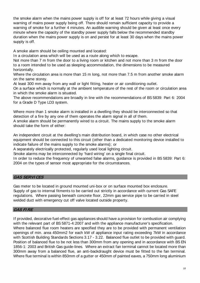
Use Honeywell SF45OEN battery operated unit, which can be fixed within the property. These are sealed units, which have a life span of six years. The batteries in the units do not require replacing. Each unit carries specific user instructions including details of the helpline if required. Refer to individual house type working drawing for exact position. Also see above for specification of detector for Housing Associations CO Alarms should be fixed:
1-3m horizontally from the appliance on the Ceiling or 150mm vertically down from the ceiling.
Above the height of any doors. Within any room where a concealed flue in a void travels to an outside wall.
Alarms must not be located: In an enclosed space i.e. cupboard. Directly above a sink. Next to a door or window. Next to an extract fan or vent. In a damp or humid location. In the immediate vicinity of a cooking appliance.
SMOKE ALARMS & HEAT ALARMS Every dwelling to be fitted with a Heat Detector to the Kitchen. A dwelling where no storey is more than 200 m2, should be provided with 1 or more smoke alarms located in the circulation space (e.g. Hallway) on each storey and 1 or more smoke alarms located within the principle habitable room (e.g. Living Room) with a standby supply to BS 5446: Part 1: 2000 and installed in accordance with the guidance in clause 2.11.2. The standby power supply for the smoke alarm should take the form of a primary battery, a secondary battery or a capacitor. The capacity of the standby supply should be sufficient to power
18
the smoke alarm when the mains power supply is off for at least 72 hours while giving a visual warning of mains power supply being off. There should remain sufficient capacity to provide a warning of smoke for a further 4 minutes. An audible warning should be given at least once every minute where the capacity of the standby power supply falls below the recommended standby duration when the mains power supply is on and persist for at least 30 days when the mains power supply is off. A smoke alarm should be ceiling mounted and located: In a circulation area which will be used as a route along which to escape. Not more than 7 m from the door to a living room or kitchen and not more than 3 m from the door to a room intended to be used as sleeping accommodation, the dimensions to be measured horizontally. Where the circulation area is more than 15 m long, not more than 7.5 m from another smoke alarm on the same storey. At least 300 mm away from any wall or light fitting, heater or air conditioning outlet. On a surface which is normally at the ambient temperature of the rest of the room or circulation area in which the smoke alarm is situated. The above recommendations are broadly in line with the recommendations of BS 5839: Part 6: 2004 for a Grade D Type LD3 system. Where more than 1 smoke alarm is installed in a dwelling they should be interconnected so that detection of a fire by any one of them operates the alarm signal in all of them. A smoke alarm should be permanently wired to a circuit. The mains supply to the smoke alarm should take the form of either: An independent circuit at the dwelling’s main distribution board, in which case no other electrical equipment should be connected to this circuit (other than a dedicated monitoring device installed to indicate failure of the mains supply to the smoke alarms); or A separately electrically protected, regularly used local lighting circuit. Smoke alarms may be interconnected by ‘hard wiring’ on a single final circuit. In order to reduce the frequency of unwanted false alarms, guidance is provided in BS 5839: Part 6: 2004 on the types of sensor most appropriate for the circumstances. GAS SERVICES Gas meter to be located in ground mounted uni-box or on surface mounted box enclosure. Supply of gas to internal fitments to be carried out strictly in accordance with current Gas SAFE regulations. Where passing beneath concrete floor, 22mm gas service pipe to be carried in steel welded duct with emergency cut off valve located outside property. GAS FIRE If provided, decorative fuel-effect gas appliances should have a provision for combustion air complying with the relevant part of BS 5871-4:2007 and with the appliance manufacturer’s specification. Where balanced flue room heaters are specified they are to be provided with permanent ventilation openings of min. area 450mm2 for each kW of appliance input rating exceeding 7kW in accordance with Scottish Building Standards Sections 3.17 - 3.22. Balanced flue outlet to be provided with guard. Position of balanced flue to be not less than 300mm from any opening and in accordance with BS EN 1856-1: 2003 and British Gas guide-lines. Where an extract fan terminal cannot be located more than 300mm away from a balanced flue, an anti-backdraught device must be fitted to the fan terminal. Where flue terminal is within 850mm of a gutter or 450mm of painted eaves, a 750mm long aluminium
19
shield must be fitted to the gutter / eaves underside. Flue to be 300mm min from edge of flue to boundary. ACCESS TO A DWELLING Driveway to be MIN 3.3m wide to allow 900mm wide pedestrian route from the parked car to the entrance door. Access paths and driveways shall be formed in accordance with 1:100 house plot plans. Access path up to house to be formed 900mm wide at MAX gradient of 1 in 12. MAX cross fall to shed off water is 1 in 40. Max length of 1 in 12 ramp is 2m. Form level landings between ramp gradients. Form unobstructed entrance platt 1200x1200, centered on principal entrance door and with a cross fall of not less than 1 in 50. Entrance door leaf to provide clear opening width of 800mm MIN, with a MIN 300mm unobstructed space adjacent to the leading edge of the door. Entrance door to incorporate an accessible threshold in accordance with 2013 Scottish Building Standards, Section 4.1.9. Ground levels to be set level with ramped access and platt levels for a MIN of 300mm before being graded away to existing levels. External steps to side and rear doors to be formed with Max rise of 170mm and MIN going of 250mm. ACCESS WITHIN A DWELLING Access throughout the principal living level to be level and include enhanced apartment, kitchen and shower room or WC with ability to be adapted to shower room at later date. Doors providing access to the above rooms to have on the principal living level to have an unobstructed area of 1100mm x 800mm space, which is clear of the door swing and orientated in the direction of entry. Corridors to be 900mm MIN width. This may reduce to 800mm over a Max length of 900mm at an obstruction such as a radiator, except on a wall opposite a doorway. Doors to have a Min clear opening width as follows to any room, including any apartment, kitchen or sanitary facility: 775mm, where the Min corridor width is 1050mm 800mm, where the Min corridor width is 900mm. (Opening width can be reduced to 775mm where a door is approached head on) APARTMENTS Every apartment to be sized to accommodate at least a bed, a wardrobe and a chest of drawers, with all associated activity spaces. Enhanced apartment: At least one apartment to be located on the principal living level with a Min floor area of 12m2 and a length and width of at least 3m. This area cannot have a headroom of less than 1.8m in height and be any portion of space allocated to a kitchen. Also to contain an unobstructed maneuvering space of at least 1.5m x 1.5m or an ellipse of at least 1.4m x 1.8m. Also to have unobstructed access, at least 800mm wide, to the controls of any openable window or any heating appliance and between doors within the apartment. Enhanced apartment also to incorporate an unobstructed area of 1100mm x 800mm space, which is clear of the door swing and orientated in the direction of entry.
20
Kitchen: Kitchen to accommodate an unobstructed space of at least 1.5m x 1.5m or an ellipse of 1.4m x 1.8m. Kitchen also to incorporate an unobstructed area of 1100mm x 800mm space, which is clear of the door swing and orientated in the direction of entry. General: All activity spaces to have Min 1.8m headroom over. ENERGY PERFORMANCE & SUSTAINABILITY Energy Performance Certificate to be displayed in each property in a prominent and readily accessible location, generally adjacent to the electricity consumer unit in ground floor hall cupboards. Sustainability Label to be displayed in each property, adjacent to EPC in hall cupboard. 30% min. improvement in CO2 emissions over 2007 Scottish Building Standards Section 6 in order to ensure compliance with 2013 Scottish Building Standards Section 6. Section 6 energy performance requirements are achieved through increase in insulation to external fabric, Flue Gas Heat Recovery (FGHR) systems and Waste Water Heat Recovery (WWHR) systems which are incorporated into those house types where the greatest benefit is achieved. Refer to development ‘Plot Specification Register’ to identify plot-specific requirements. SECURITY All entrance doors & ground floor windows to dwellings to be designed & installed to resist forced entry in accordance with the requirements of Building Scotland Regulations 2013 Standard 4.13.1 by the use of door sets & windows manufactured to meet recognised product standards & defined component performance. THERMAL BRIDGING The Y-value calculations of overall thermal bridging for each individual house type are based on the thermally modelled PSI values as per appendix C.