Embed Size (px)
Citation preview


Banner AG4 Series Safety Laser Scanner
2 P/N 144924 rev. A 02/2010 AG4 Safety Laser Scanner User Manual
Important . . . read this page before proceeding!
In the United States, the functions that the Banner AG4 Series Safety Laser Scanner is intended to perform are regulated by the Occupational Safety and Health Administration (OSHA). Outside of the United States, these functions are regulated by other agencies, organizations, and governments. Whether or not any particular Safety Laser Scanner installation meets all applicable requirements depends upon factors that are beyond the control of Banner Engineering Corp. These factors include the way in wh ich the Safety Laser Scanner is applied, installed, wired, operated, and maintained. It is the responsibility of the purchaser and user to apply this Safety Laser Scanner in full compliance with all relevant applicable regulations and standards.
The Banner AG4 Series Safety Laser Scanner can guard against accidents only when it is properly installed and integrated into the machine, properly operated, and properly maintained. Banner Engineering Corp. has attempted to provide complete application, installation, operation, and maintenance instructions. In addition, please direct any questions regarding application or use of the Scanner to the factory applications department at the telephone number or addresses shown on the back cover.
In addition to OSHA regulations, several other organizations provide information about the use of safeguarding devices. Refer to the American National Standards Institute (ANSI), the Robotics Industries Association (RIA), the Association for Manufacturing Technology (AMT), and others. Banner Engineering Corp. makes no claim regarding a specific recommendation of any organization, the accuracy or effectiveness of any information provided, or the appropriateness of the provided information for a specific application.
The user has the responsibility to ensure that all local, state, and national laws, rules, codes, and regulations relating to the use of this safeguarding system in any particular application are satisfied. Extreme care is urged to ensure that all leg al requirements are met and that all installation and maintenance instructions contained in this manual are followed.
Safety Standards Applicable to Use of this Product
See inside back cover for information pertaining to applicable U.S. and International standards, and where to acquire copies.
Certificate of Adequacy
This instruction manual (P/N 144924) satisfies the requirements of Machinery Directive 2006/42/EC, Section 1.7.4 – Instructions.
Banner AG4 Series Safety Laser Scanner
Banner AG4 Series User Manual P/N 144924 rev. A 02/2010 3
About this Document
The information for applying and configuring the Banner AG4 Safety Laser Scanner (the Scanner) is covered in several documents to simplify access to information. The documents and configuration program for the Scanner are on the CD that comes with the product. The current software version and all PDF documents can also be downloaded from the Banner website http://www.bannerengineering.com.
Print out the relevant instructions to simplify reading and handling the documents.
Document Title Document Content Source
AG4 Series Safety Laser Scanner Quick-Reference User Guide
General product information and diagnostic reference
P/N 145034, included with the product in print and on CD-ROM
AG4soft Program Configuration and diagnostic software AG4soft, included with the product on CD-ROM
AG4 Series Safety Laser Scanner User Manual (this document)
AG4 operation capabilities, functions, and applications, for the machine designer, installer and end user
P/N 144924, included with the product on CD-ROM
AG4 Software Manual
How to: configure operational settings, access diagnostic information, and manage configuration files
P/N 144923, included with the product on CD-ROM
AG4 Series Safety Laser Scanner Applications Guide
Application examples intended to give additional guidance in applying the Scanner
P/N 147900, included with the product on CD-ROM
AG4 Series Safety Laser Scanner Checkout Cards
Instructions for daily and semi-annual checkouts of Scanner installation
P/N 147899, included with the product on CD-ROM, to print as needed and post near the guarded equipment
Banner AG4 Series Safety Laser Scanner
4 P/N 144924 rev. A 02/2010 AG4 Safety Laser Scanner User Manual
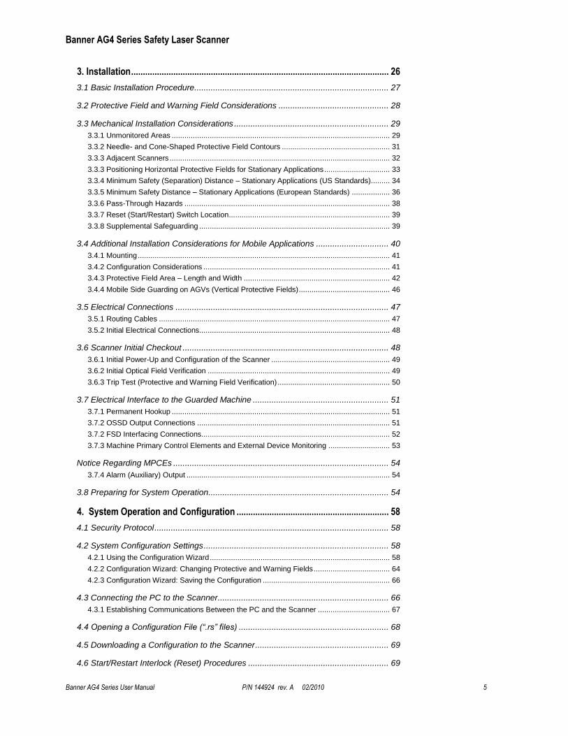
Table of Contents
Safety Standards Applicable to Use of this Product ................................................ 2
Certificate of Adequacy .................................................................................................. 2
About this Document ...................................................................................................... 3
1. Overview ................................................................................................................... 7
1.1 Status Display .......................................................................................................... 7
1.2 Mounting System (Optional)..................................................................................... 8
1.3 Machine Interface X1 ConfigPlug ............................................................................. 8
1.4 Product Labels ......................................................................................................... 9 1.4.1 Product Identification Plate .............................................................................................. 9 1.4.2 Safety Notice................................................................................................................... 9
1.5 Proper Use and Intended Purpose ........................................................................... 9
1.6 Security Protocol and Checkout Procedures.......................................................... 10 1.6.1 Designated Person........................................................................................................ 10 1.6.2 Qualified Person ........................................................................................................... 10
1.7 Responsibility for Safety ........................................................................................ 10 1.7.1 Passwords .................................................................................................................... 11 1.7.2 Providing Information for Use ........................................................................................ 11
1.8 Laser ...................................................................................................................... 11
1.9 High Voltage .......................................................................................................... 11
1.10 Handling the Scanner .......................................................................................... 12
1.11 Scanner Limitations ............................................................................................. 12
1.12 Basic Operation Functions .................................................................................. 12 1.12.1 Start/Restart (Reset) Interlock ..................................................................................... 13 1.12.2 Start Test .................................................................................................................... 14 1.12.3 Dust Suppression ........................................................................................................ 14 1.12.4 Field Pairs: Independently Activated Protective and Warning Fields ............................ 14 1.12.5 Reference Contour (Surface) Monitoring ..................................................................... 17 1.12.6 Alarm (Auxiliary) Outputs ........................................................................................... 17
2. Models and Specifications .................................................................................... 19
2.1 Models, Accessories and Replacement Parts ........................................................ 19 2.1.1 Cordsets and Connections ............................................................................................ 19 2.1.2 Accessories .................................................................................................................. 19 2.1.3 Replacement Parts........................................................................................................ 20
2.2 Specifications ......................................................................................................... 20
2.3 Dimensions ............................................................................................................ 22
2.4 Connector Plug Assignments ................................................................................. 24
Banner AG4 Series Safety Laser Scanner
Banner AG4 Series User Manual P/N 144924 rev. A 02/2010 5
3. Installation .............................................................................................................. 26
3.1 Basic Installation Procedure................................................................................... 27
3.2 Protective Field and Warning Field Considerations ............................................... 28
3.3 Mechanical Installation Considerations .................................................................. 29 3.3.1 Unmonitored Areas ....................................................................................................... 29 3.3.2 Needle- and Cone-Shaped Protective Field Contours ................................................... 31 3.3.3 Adjacent Scanners ........................................................................................................ 32 3.3.3 Positioning Horizontal Protective Fields for Stationary Applications ............................... 33 3.3.4 Minimum Safety (Separation) Distance – Stationary Applications (US Standards) ......... 34 3.3.5 Minimum Safety Distance – Stationary Applications (European Standards) .................. 36 3.3.6 Pass-Through Hazards ................................................................................................. 38 3.3.7 Reset (Start/Restart) Switch Location ............................................................................ 39 3.3.8 Supplemental Safeguarding .......................................................................................... 39
3.4 Additional Installation Considerations for Mobile Applications ............................... 40 3.4.1 Mounting ....................................................................................................................... 41 3.4.2 Configuration Considerations ........................................................................................ 41 3.4.3 Protective Field Area – Length and Width ..................................................................... 42 3.4.4 Mobile Side Guarding on AGVs (Vertical Protective Fields) ........................................... 46
3.5 Electrical Connections ........................................................................................... 47 3.5.1 Routing Cables ............................................................................................................. 47 3.5.2 Initial Electrical Connections.......................................................................................... 48
3.6 Scanner Initial Checkout ........................................................................................ 48 3.6.1 Initial Power-Up and Configuration of the Scanner ........................................................ 49 3.6.2 Initial Optical Field Verification ...................................................................................... 49 3.6.3 Trip Test (Protective and Warning Field Verification) ..................................................... 50
3.7 Electrical Interface to the Guarded Machine .......................................................... 51 3.7.1 Permanent Hookup ....................................................................................................... 51 3.7.2 OSSD Output Connections ........................................................................................... 51 3.7.2 FSD Interfacing Connections......................................................................................... 52 3.7.3 Machine Primary Control Elements and External Device Monitoring ............................. 53
Notice Regarding MPCEs ............................................................................................ 54 3.7.4 Alarm (Auxiliary) Output ................................................................................................ 54
3.8 Preparing for System Operation ............................................................................. 54
4. System Operation and Configuration ................................................................. 58
4.1 Security Protocol .................................................................................................... 58
4.2 System Configuration Settings ............................................................................... 58 4.2.1 Using the Configuration Wizard ..................................................................................... 58 4.2.2 Configuration Wizard: Changing Protective and Warning Fields .................................... 64 4.2.3 Configuration Wizard: Saving the Configuration ............................................................ 66
4.3 Connecting the PC to the Scanner ......................................................................... 66 4.3.1 Establishing Communications Between the PC and the Scanner .................................. 67
4.4 Opening a Configuration File (“.rs” files) ................................................................ 68
4.5 Downloading a Configuration to the Scanner ......................................................... 69
4.6 Start/Restart Interlock (Reset) Procedures ............................................................ 69
Banner AG4 Series Safety Laser Scanner
6 P/N 144924 rev. A 02/2010 AG4 Safety Laser Scanner User Manual
4.6.1 Resetting the System .................................................................................................... 69
4.7 Status Indicators .................................................................................................... 69
4.8 Normal Operation ................................................................................................... 69 4.8.1 System Power-Up ......................................................................................................... 70 4.8.2 During Run Mode .......................................................................................................... 70
4.9 Determining Response Time .................................................................................. 70
4.10 Periodic Checkout Requirements ......................................................................... 71
5. Troubleshooting and Maintenance ...................................................................... 72
5.1 Troubleshooting Lockout Conditions ...................................................................... 72 5.1.1 Scanner LED Status Display ......................................................................................... 72 5.1.2 LED Status Displays ..................................................................................................... 74
5.1.3 LED Warning and Error Displays ........................................................................ 75 5.1.2 Scanner Error Codes .................................................................................................... 76
5.2 Communication Errors and Loss of Communication .............................................. 82 5.2.1 AG4Soft Pop-up Error Messages .................................................................................. 82
5.3 Electrical and Optical Noise ................................................................................... 83
5.4 Servicing and Maintenance .................................................................................... 83 5.4.1 Removing the Scanner from the Machine ...................................................................... 83 5.4.2 Cleaning the Front Screen (Window) and Scatter Screens ............................................ 83 5.4.3 Cleaning the Scatter Screens ........................................................................................ 84 5.4.4 Changing the Front Screen (Window)........................................................................... 85 5.4.5 Calibrating the Front Screen (Window) .......................................................................... 86 5.4.6 Scanner Replacement Procedure.................................................................................. 87
5.5 Repairs and Warranty Service ............................................................................... 87
6. Safety System Testing ......................................................................................... 88
6.1 Schedule of Checkouts .......................................................................................... 88
6.2 Commissioning Checkout ...................................................................................... 89
6.3 Shift/Daily Checkout ............................................................................................... 91
6.4 Semi-Annual (Six-Month) Checkout ....................................................................... 91
7. Glossary ................................................................................................................ 92
7.1 List of Abbreviations ............................................................................................... 92
7.2 List of Terms .......................................................................................................... 92
EC Declaration of Conformity ................................................................................... 94
Banner AG4 Series Safety Laser Scanner
Banner AG4 Series User Manual P/N 144924 rev. A 02/2010 7
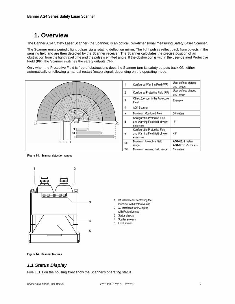
1. Overview The Banner AG4 Safety Laser Scanner (the Scanner) is an optical, two-dimensional measuring Safety Laser Scanner.
The Scanner emits periodic light pulses via a rotating deflection mirror. The light pulses reflect back from objects in the sensing field and are then detected by the Scanner receiver. The Scanner calculates the precise position of an obstruction from the light travel time and the pulse’s emitted angle. If the obstruction is within the user-defined Protective Field (PF), the Scanner switches the safety outputs OFF.
Only when the Protective Field is free of obstructions does the Scanner turn its safety outputs back ON, either automatically or following a manual restart (reset) signal, depending on the operating mode.
1 Configured Warning Field (WF) User defines shapes
and ranges
2 Configured Protective Field (PF) User defines shapes
and ranges
3 Object (person) in the Protective
Field Example
4 AG4 Scanner
a Maximum Monitored Area 50 meters
d
Configurable Protective Field
and Warning Field field of view
extension
-5°
e
Configurable Protective Field
and Warning Field field of view
extension
+5°
PF Maximum Protective Field
range
AG4-4E: 4 meters
AG4-6E: 6.25 meters
WF Maximum Warning Field range 15 meters
Figure 1-1. Scanner detection ranges
1 X1 interface for controlling the
machine, with Protective cap
2 X2 interfaces for PC/laptop,
with Protective cap
3 Status display
4 Scatter screens
5 Front screen
Figure 1-2. Scanner features
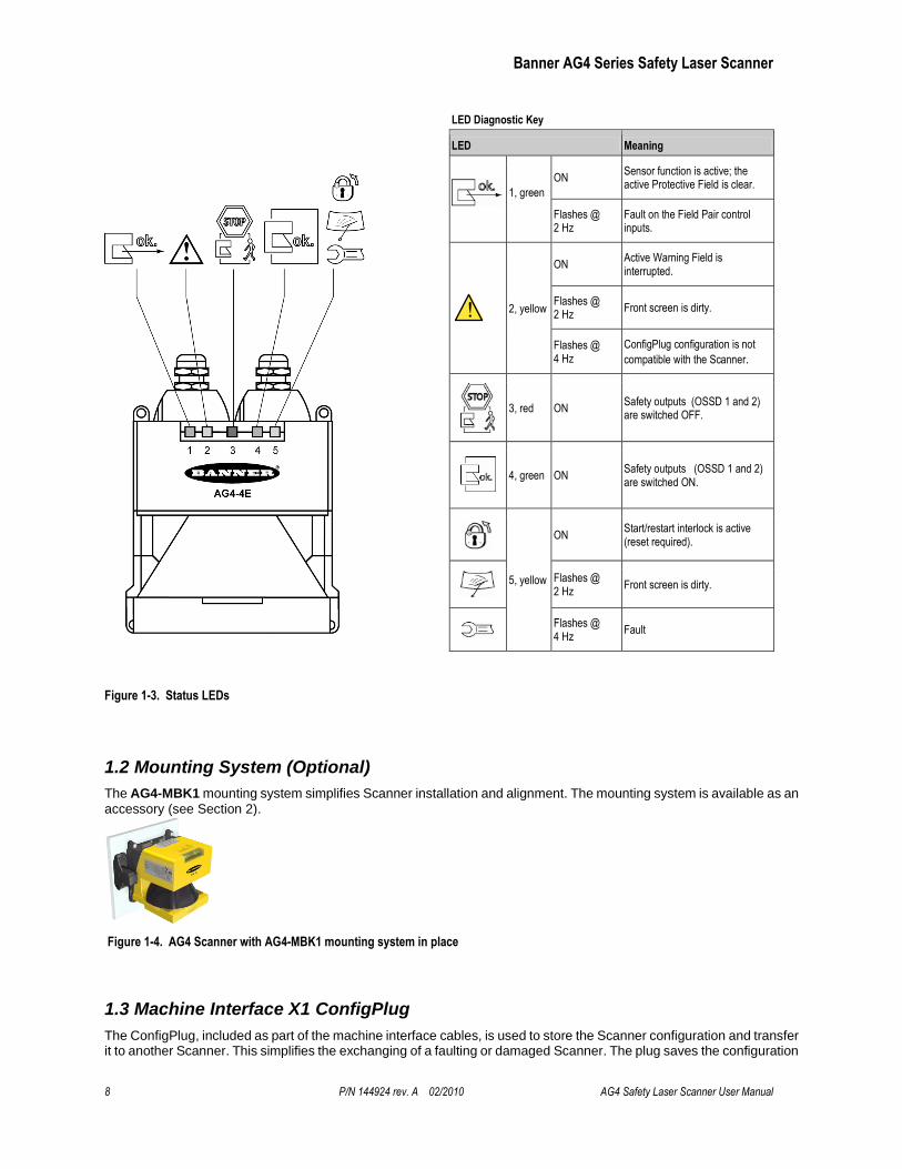
1.1 Status Display
Five LEDs on the housing front show the Scanner's operating status.
Banner AG4 Series Safety Laser Scanner
8 P/N 144924 rev. A 02/2010 AG4 Safety Laser Scanner User Manual
LED Diagnostic Key
LED Meaning
1, green
ON Sensor function is active; the active Protective Field is clear.
Flashes @ 2 Hz
Fault on the Field Pair control inputs.
2, yellow
ON Active Warning Field is interrupted.
Flashes @ 2 Hz
Front screen is dirty.
Flashes @ 4 Hz
ConfigPlug configuration is not
compatible with the Scanner.
3, red ON Safety outputs (OSSD 1 and 2) are switched OFF.
4, green ON Safety outputs (OSSD 1 and 2) are switched ON.
5, yellow
ON Start/restart interlock is active (reset required).
Flashes @ 2 Hz
Front screen is dirty.
Flashes @ 4 Hz
Fault
Figure 1-3. Status LEDs
1.2 Mounting System (Optional)
The AG4-MBK1 mounting system simplifies Scanner installation and alignment. The mounting system is available as an
accessory (see Section 2).
Figure 1-4. AG4 Scanner with AG4-MBK1 mounting system in place
1.3 Machine Interface X1 ConfigPlug
The ConfigPlug, included as part of the machine interface cables, is used to store the Scanner configuration and transfer it to another Scanner. This simplifies the exchanging of a faulting or damaged Scanner. The plug saves the configuration
Banner AG4 Series Safety Laser Scanner
Banner AG4 Series User Manual P/N 144924 rev. A 02/2010 9
when the PC transfers the operational parameters to the Scanner. When the original Scanner is replaced and a new Scanner is connected to power with the ConfigPlug, the plug automatically transfers the configuration into the new Scanner.
1.4 Product Labels
1.4.1 Product Identification Plate
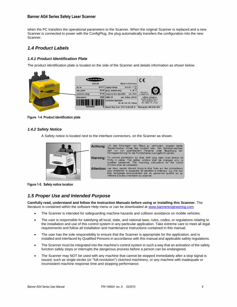
The product identification plate is located on the side of the Scanner and details information as shown below.
Figure 1-4. Product identification plate
1.4.2 Safety Notice
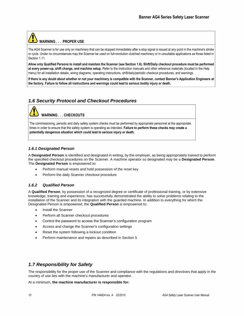
A Safety notice is located next to the interface connectors, on the Scanner as shown.
Figure 1-5. Safety notice location
1.5 Proper Use and Intended Purpose
Carefully read, understand and follow the Instruction Manuals before using or installing this Scanner. The
literature is contained within the software Help menu or can be downloaded at www.bannerengineering.com.
The Scanner is intended for safeguarding machine hazards and collision avoidance on mobile vehicles.
The user is responsible for satisfying all local, state, and national laws, rules, codes, or regulations relating to the installation and use of this control system in any particular application. Take extreme care to meet all legal requirements and follow all installation and maintenance instructions contained in this manual.
The user has the sole responsibility to ensure that the Scanner is appropriate for the application, and is installed and interfaced by Qualified Persons in accordance with this manual and applicable safety regulations.
The Scanner must be integrated into the machine's control system in such a way that an activation of the safety function safely stops or interrupts the dangerous process before a person can be endangered.
The Scanner may NOT be used with any machine that cannot be stopped immediately after a stop signal is issued, such as single-stroke (or "full-revolution") clutched machinery, or any machine with inadequate or inconsistent machine response time and stopping performance.
Banner AG4 Series Safety Laser Scanner
10 P/N 144924 rev. A 02/2010 AG4 Safety Laser Scanner User Manual
1.6 Security Protocol and Checkout Procedures
WARNING . . . CHECKOUTS
The commissioning, periodic and daily safety system checks must be performed by appropriate personnel at the appropriate
times in order to ensure that the safety system is operating as intended. Failure to perform these checks may create a
potentially dangerous situation which could lead to serious injury or death.
1.6.1 Designated Person
A Designated Person is identified and designated in writing, by the employer, as being appropriately trained to perform the specified checkout procedures on the Scanner. A machine operator so designated may be a Designated Person. The Designated Person is empowered to:
Perform manual resets and hold possession of the reset key
Perform the daily Scanner checkout procedure
1.6.2 Qualified Person
A Qualified Person, by possession of a recognized degree or certificate of professional training, or by extensive
knowledge, training and experience, has successfully demonstrated the ability to solve problems relating to the installation of the Scanner and its integration with the guarded machine. In addition to everything for which the Designated Person is empowered, the Qualified Person is empowered to:
Install the Scanner
Perform all Scanner checkout procedures
Control the password to access the Scanner’s configuration program
Access and change the Scanner’s configuration settings
Reset the system following a lockout condition
Perform maintenance and repairs as described in Section 5
1.7 Responsibility for Safety
The responsibility for the proper use of the Scanner and compliance with the regulations and directives that apply in the country of use lies with the machine's manufacturer and operator.
At a minimum, the machine manufacturer is responsible for:
WARNING . . . PROPER USE
The AG4 Scanner is for use only on machinery that can be stopped immediately after a stop signal is issued at any point in the machine's stroke
or cycle. Under no circumstances may the Scanner be used on full-revolution clutched machinery or in unsuitable applications as those listed in
Section 1.11.
Allow only Qualified Persons to install and maintain the Scanner (see Section 1.6). Shift/Daily checkout procedure must be performed
at every power-up, shift change, and machine setup. Refer to the instruction manuals and other reference materials (located in the Help
menu) for all installation details, wiring diagrams, operating instructions, shift/daily/periodic checkout procedures, and warnings.
If there is any doubt about whether or not your machinery is compatible with the Scanner, contact Banner's Application Engineers at
the factory. Failure to follow all instructions and warnings could lead to serious bodily injury or death.
Banner AG4 Series Safety Laser Scanner
Banner AG4 Series User Manual P/N 144924 rev. A 02/2010 11
The safe design and construction of the machine.
The safe implementation of the Scanner.
Providing all relevant information to the user (e.g., all documentation provided with the AG4).
Compliance with all regulations and directives that allow the user to safely put the machine into operation.
At a minimum, the machine user is responsible for:
Instructing and supervising the Qualified Person, the Designated Person, and the operator.
Maintaining the safe operation of the machine.
Compliance with all occupational health and safety at work regulations and directives.
1.7.1 Passwords
Improperly set parameters on the Scanner can cause serious accidents. The configuration of the Scanner is therefore protected by passwords.
Ensure that the passwords are secured by the Qualified Person. The default password is "bannera"; call the
numbers on the back cover for assistance in the event of a lost password.
The people responsible for the machine's safety must ensure that the appropriately Qualified Person can properly perform the tests and work on the machine and the Scanner in accordance with their intended use.
1.7.2 Providing Information for Use
WARNING . . . SCANNER OPERATION ON POWER-UP
It is the responsibility of the user of the Scanner to assess what safeguarding devices and methods are appropriate for any given machine or
application. The Qualified Person who configures, installs, and/or maintains it must be aware of the power-up behavior of the Scanner
and instruct the machine operator on the operation of the Scanner.
At a minimum, the machine manufacturer must provide information to the user to inform the operator of the requirements for the safe operation of the machine and the Scanner. This also includes providing the necessary instructions needed by the Designated Person or operator to ensure the safe use of the Scanner (e.g., checkout procedures). The machine operational instruction materials may never describe a situation that could expose an operator to a hazard.
1.8 Laser
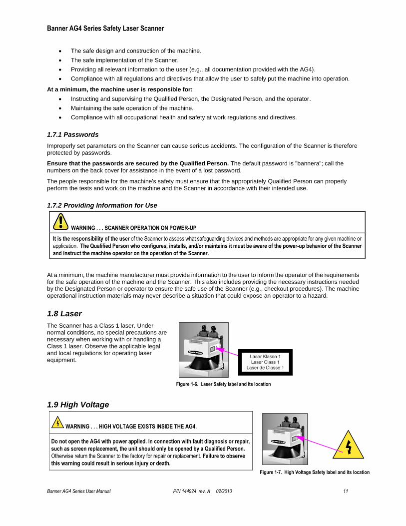
The Scanner has a Class 1 laser. Under normal conditions, no special precautions are necessary when working with or handling a Class 1 laser. Observe the applicable legal and local regulations for operating laser equipment.
Figure 1-6. Laser Safety label and its location
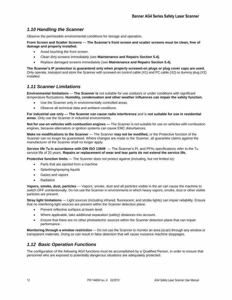
1.9 High Voltage
WARNING . . . HIGH VOLTAGE EXISTS INSIDE THE AG4.
Do not open the AG4 with power applied. In connection with fault diagnosis or repair,
such as screen replacement, the unit should only be opened by a Qualified Person.
Otherwise return the Scanner to the factory for repair or replacement. Failure to observe
this warning could result in serious injury or death.
Figure 1-7. High Voltage Safety label and its location
Banner AG4 Series Safety Laser Scanner
12 P/N 144924 rev. A 02/2010 AG4 Safety Laser Scanner User Manual
1.10 Handling the Scanner
Observe the permissible environmental conditions for storage and operation.
Front Screen and Scatter Screens — The Scanner’s front screen and scatter screens must be clean, free of damage and properly installed.
Avoid touching the front screen.
Clean dirty screens immediately (see Maintenance and Repairs Section 5.4).
Replace damaged screens immediately (see Maintenance and Repairs Section 5.4).
The Scanner’s IP protection is guaranteed only when properly screwed-on plugs or plug cover caps are used.
Only operate, transport and store the Scanner with screwed-on control cable (X1) and PC cable (X2) or dummy plug (X2) installed.
1.11 Scanner Limitations
Environmental limitations — The Scanner is not suitable for use outdoors or under conditions with significant temperature fluctuations. Humidity, condensation and other weather influences can impair the safety function.
Use the Scanner only in environmentally controlled areas.
Observe all technical data and ambient conditions.
For industrial use only — The Scanner can cause radio interference and is not suitable for use in residential areas. Only use the Scanner in industrial environments.
Not for use on vehicles with combustion engines — The Scanner is not suitable for use on vehicles with combustion
engines, because alternators or ignition systems can cause EMC disturbances.
Make no modifications to the Scanner — The Scanner may not be modified, or the Protective function of the
Scanner can no longer be guaranteed. Where changes are made to the Scanner, all guarantee claims against the manufacturer of the Scanner shall no longer apply.
Service life TM in accordance with DIN ISO 13849 — The Scanner’s PL and PFHd specifications refer to the TM service life of 20 years. Repairs or replacement of wear and tear parts do not extend the service life.
Protective function limits — The Scanner does not protect against (including, but not limited to):
Parts that are ejected from a machine
Splashing/spraying liquids
Gases and vapors
Radiation
Vapors, smoke, dust, particles — Vapors, smoke, dust and all particles visible in the air can cause the machine to
switch OFF unintentionally. Do not use the Scanner in environments in which heavy vapors, smoke, dust or other visible particles are present.
Stray light limitations — Light sources (including infrared, fluorescent, and strobe lights) can impair reliability. Ensure
that no interfering light sources are present within the Scanner detection plane.
Prevent reflective surfaces at beam level.
Where applicable, take additional separation (safety) distances into account.
Ensure that there are no other photoelectric sources within the Scanner detection plane that can impair performance.
Monitoring through a window restriction — Do not use the Scanner to monitor an area (scan) through any window or
transparent materials. Doing so can result in false detection that will cause nuisance machine stoppages.
1.12 Basic Operation Functions
The configuration of the following AG4 functions must be accomplished by a Qualified Person, in order to ensure that personnel who are exposed to potentially dangerous situations are adequately protected.
Banner AG4 Series Safety Laser Scanner
Banner AG4 Series User Manual P/N 144924 rev. A 02/2010 13
1.12.1 Start/Restart (Reset) Interlock
WARNING . . . MANUAL and AUTOMATIC START/RESTART (RESET)
Application of power to the Scanner components, the clearing of the Protected Field (PF), or the reset of a start/restart interlock
condition MUST NOT initiate dangerous machine motion. Machine control circuitry must be designed so that one or more initiation devices
must be engaged (i.e., a conscious act) to start the machine – in addition to the Scanner turning ON its safety outputs (OSSD1 and OSSD2).
Failure to do so could cause a machine to operate in an unexpected way, resulting in serious bodily injury or death.
Warning . . . START/RESTART (RESET) SWITCH LOCATION
The system Start/Restart (Reset) switch must be accessible only from outside, and in full view of, the hazardous area. Reset switches
must also be out of reach from within the safeguarded space, and must be protected against unauthorized or inadvertent operation (via
rings, guards, key or other means). If any areas are not visible from the reset switch, additional means of safeguarding must be provided. Failure
to do so could result in serious bodily injury or death.
The start/restart (reset) interlock has two functions:
1. Start interlock
2. Restart interlock
This interlock function is used to enable the machine’s normal start command. Actuating (cycling) this input must not cause hazardous motion or a hazardous situation. After clearing the AG4 start/restart interlock, a second, deliberate action by the operator (e.g., actuating the machine cycle start switch) is required to begin or resume the machine’s operation.
Using Start/Restart (Reset) Interlock
Install an appropriate start/restart switch (see Specifications), which causes the Scanner outputs to turn ON when the switch is actuated.
Position the start/restart switch outside the hazardous area so that it cannot be activated from within the hazardous areas. The operator must be able to see all hazardous areas from this position.
Label the start/restart switch with the safeguarding device (e.g., Scanner) to be reset, so that the safeguarded area is easy to identify.
Ensure that no personnel are in the hazardous area before actuating the start/restart switch.
Start Interlock
The start interlock function prevents the AG4 outputs (OSSD1 and OSSD2) from automatically turning ON when power is initially applied to the AG4 (either initially or after an interruption of power and its return).
The Scanner outputs will turn ON only after the Protective Field (PF) is clear and the start/restart switch is actuated.
Restart Interlock
Manual Restart (Manual Reset) when the Protective Field (PF) is Clear: The restart interlock prevents the AG4
outputs (OSSD1 and OSSD2) from automatically turning ON as soon as the Protective Field is clear. The restart interlock function always includes the start interlock function.
Scanner outputs turn ON only when the Protective Field is clear and the start/restart (reset) switch is actuated.
Automatic Start/Restart (Auto Reset) when the Protective Field (PF) is Clear: The automatic start/restart function enables the Scanner's safety outputs to turn ON after power is applied, if and when the Protective Field is clear, and
after the ―Restart Delay Time‖ has expired.
The automatic start/restart function may be used only under the following conditions:
Banner AG4 Series Safety Laser Scanner
14 P/N 144924 rev. A 02/2010 AG4 Safety Laser Scanner User Manual
Machine control circuitry is designed so that one or more initiation devices must be engaged (i.e., a conscious act is required) to start the machine – in addition to the Scanner turning ON its safety outputs (OSSD1 and OSSD2).
or
It is not otherwise possible to access the hazard area, except while being continually detected by the Protective Field.
1.12.2 Start Test
The start test function requires the operator to interrupt and then clear the Protective Field with a test rod after the
Scanner is powered up. Only then will the Scanner outputs turn ON, so the machine can be started. The function is available only when Auto Reset is selected.
When the start test is combined with the automatic restart function, the start test serves as a start/restart signal.
1.12.3 Dust Suppression
The dust suppression function increases the reliability of the Scanner when small particles are in the air, e.g. material chips or insects. Deactivate the dust suppression function when the Scanner must detect extremely fast or small objects in the application.
1.12.4 Field Pairs: Independently Activated Protective and Warning Fields
Through the use of the Field Pair (FP) inputs, external logic (e.g., a PLC) is capable of selecting one of eight configured Field Pairs stored in the Scanner at any given time. A Field Pair is defined as the combination of a configured Protective Field (PF) and a Warning Field (WF). When active (see Table 1), a specific Field Pair is in sole control of the safety outputs (OSSD1 and OSSD2) and the ALARM 1 auxiliary output. This function is useful to change the safeguarded area in an application in which a hazard is not continually present or in mobile applications in which direction, speed and stopping distance varies.
After the Scanner is configured, switching over or ―activating‖ an individual Field Pair is controlled by the four ―FP‖ inputs on the Machine Interface X1 plug (see Table 1 and Figures 3-18, 3-19, and 3-20).
WARNING . . . PROTECTIVE FIELD PAIR SWITCHING
Field Pair Switching is used to temporarily suspend or change the area of safeguarding. Changing the Protective/Warning Field Pair from one
pair to another must not expose any individual to a hazard or hazardous situation. Supplemental safeguarding may be required.
In higher-risk applications, use redundant sensors or switches to initiate or enable a Field Pair change.
The conditions for switching Field Pairs must be in accordance with a risk assessment. Machine stopping/braking distances, Scanner system response time (including interfacing devices), machine stop time and other factors that influence the Safety Distance (Minimum Distance) and Stopping Distance calculations must be considered in order to safely use the Field Pair Switchover function.
Conditions to Allow Switching Field Pairs:
Only one Field Pair can be active after the switchover time. See Field Pair Input Logic table 1.
Field Pair switchover is allowed even if there is an intrusion into the active Protective Field (i.e., OSSDs are OFF).
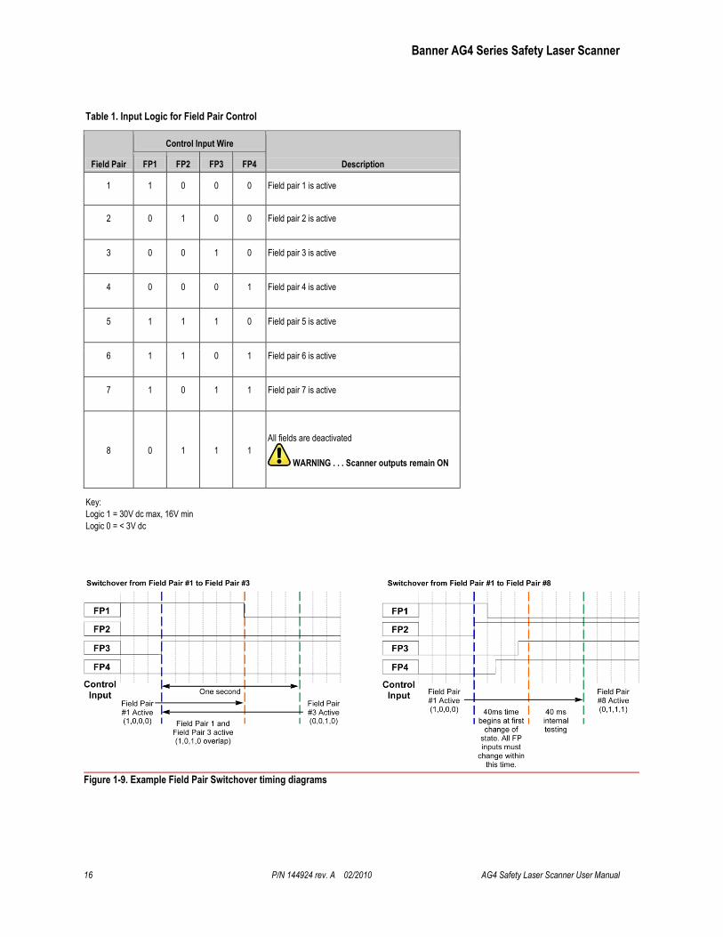
The switchover must be made within one second, except when Field Pairs 5, 6, 7, or 8 are configured, at which time the switchover must occur within 40 ms. In this case, the original Field Pair is active during the switchover; the new Field Pair becomes active after a maximum of 80 ms. See timing diagram, Figure 1-9.
Banner AG4 Series Safety Laser Scanner
Banner AG4 Series User Manual P/N 144924 rev. A 02/2010 15
Note: Due to the timing requirements, it is recommended that the selection of Field Pairs 5, 6, 7, or 8 be made via PC, PES, or PLC logic. Additional switches or sensors can be used to enable (allow) Field Pair switchover.
For switching between Field Pairs 1, 2, 3, and 4, the new Field Pair(s) is active before the original Field Pair is deactivated (Field Pairs ―overlap‖) during the one-second switchover time limit. See timing diagram Figure 1-9.
If no Field Pairs are selected (active) after the switchover time, a lockout will occur (i.e., all FP inputs are 0V dc or an open connection).
Selecting an invalid Field Pair(s) or not completing the selection within the switchover time will result in a lockout.
Selecting Field Pairs that are not configured will result in a lockout.
Switching between Field Pairs that are not allowed per the ―Permitted Field Pair switchover‖ table will result in a lockout. See the AG4Soft Software Manual.
The Scanner is allowed to power up (see Section 1.12.1 Start/Restart (Reset) Interlock) with Field Pair 1 through 7 selected as configured in the Field Pair ―Scanner start‖ table. See the AG4Soft Software Manual and ―Field Pair 8‖ below for more information.
In addition, factors dependent on the risk assessment that may affect the safety circuit integrity level include:
The means of selecting Field Pairs must be analyzed in respect of failure modes to ensure that an unintended switchover does not occur. In higher risk applications, it is highly recommended to use redundant sensors or switches to initiate or enable a Field Pair change. Diverse technology can minimize the possibility of common cause or common mode failures.
Ensure that selecting/deselecting Field Pairs does not expose any individual to a hazard. Supplemental safeguarding may be required.
Field Pair 8
Field pair 8 is pre-configured and is not user-adjustable. Its Protective Field and Warning Field are deactivated and its OSSD (safety) outputs and ALARM 1 auxiliary output remain ON (unless a lockout occurs). This Field Pair must only be used when there is no exposure to any hazard. Supplemental safeguarding may be required during the selection
of Field Pair 8.
It is not possible to power up (start) when Field Pair 8 is selected. Field pairs 1 through 7 (typically the Field Pair with the largest Protective Field) must be selected at power-up and then a switchover to Field Pair 8 can be accomplished according to the conditions stated above. It is allowed to switch over from Field Pair 8 to any configured Field Pair.
WARNING . . . FIELD PAIR 8 FUNCTION
Field Pair 8 deactivates the entire Protective Field and Warning Field monitoring function of the Scanner. This creates a condition where
the Scanner OSSD safety outputs are always ON, even if an individual enters the potentially hazardous area.
Enable (select) Field Pair 8 only when personnel are not exposed to a hazard.
Failure to follow these recommendations can potentially create a dangerous situation that may lead to serious injury or death.
Banner AG4 Series Safety Laser Scanner
16 P/N 144924 rev. A 02/2010 AG4 Safety Laser Scanner User Manual
Table 1. Input Logic for Field Pair Control
Field Pair
Control Input Wire
Description FP1 FP2 FP3 FP4
1 1 0 0 0 Field pair 1 is active
2 0 1 0 0 Field pair 2 is active
3 0 0 1 0 Field pair 3 is active
4 0 0 0 1 Field pair 4 is active
5 1 1 1 0 Field pair 5 is active
6 1 1 0 1 Field pair 6 is active
7 1 0 1 1 Field pair 7 is active
8 0 1 1 1
All fields are deactivated
WARNING . . . Scanner outputs remain ON
Key:
Logic 1 = 30V dc max, 16V min
Logic 0 = < 3V dc
Figure 1-9. Example Field Pair Switchover timing diagrams
Banner AG4 Series Safety Laser Scanner
Banner AG4 Series User Manual P/N 144924 rev. A 02/2010 17
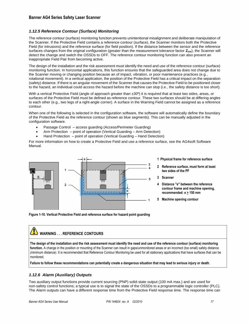
1.12.5 Reference Contour (Surface) Monitoring
The reference contour (surface) monitoring function prevents unintentional misalignment and deliberate manipulation of the Scanner. If the Protective Field contains a reference contour (surface), the Scanner monitors both the Protective Field (for intrusions) and the reference surface (for field position). If the distance between the sensor and the reference surfaces changes from the original configuration (greater than the measurement tolerance factor Zsm), the Scanner will
detect the change and switch the OSSDs to OFF. The reference contour monitoring function can also prevent an inappropriate Field Pair from becoming active.
The design of the installation and the risk assessment must identify the need and use of the reference contour (surface) monitoring function. In horizontal applications, this function ensures that the safeguarded area does not change due to the Scanner moving or changing position because an of impact, vibration, or poor maintenance practices (e.g., rotational movement). In a vertical application, the position of the Protective Field has a critical impact on the separation (safety) distance. If there is an angular movement of the Scanner that causes the Protective Field to be positioned closer to the hazard, an individual could access the hazard before the machine can stop (i.e., the safety distance is too short).
With a vertical Protective Field (angle of approach greater than ±30º) it is required that at least two sides, areas, or surfaces of the Protective Field must be defined as reference contour. These two surfaces should be at differing angles to each other (e.g., two legs of a right-angle corner). A surface in the Warning Field cannot be assigned as a reference contour.
When one of the following is selected in the configuration software, the software will automatically define the boundary of the Protective Field as the reference contour (shown as blue segments). This can be manually adjusted in the configuration software.
Passage Control – access guarding (Access/Perimeter Guarding)
Arm Protection – point of operation (Vertical Guarding – Arm Detection)
Hand Protection – point of operation (Vertical Guarding – Hand Detection)
For more information on how to create a Protective Field and use a reference surface, see the AG4soft Software Manual.
1 Physical frame for reference surface
2 Reference surface, must form at least two sides of the PF
3 Scanner
4 Distance "e" between the reference contour frame and machine opening, recommended: e > 150 mm
5 Machine opening contour
Figure 1-10. Vertical Protective Field and reference surface for hazard point guarding
WARNING . . . REFERENCE CONTOURS
The design of the installation and the risk assessment must identify the need and use of the reference contour (surface) monitoring
function. A change in the position or mounting of the Scanner can result in gaps/unmonitored areas or an incorrect (too small) safety distance
(minimum distance). It is recommended that Reference Contour Monitoring be used for all stationary applications that have surfaces that can be
monitored.
Failure to follow these recommendations can potentially create a dangerous situation that may lead to serious injury or death.
1.12.6 Alarm (Auxiliary) Outputs
Two auxiliary output functions provide current sourcing (PNP) solid-state output (100 mA max.) and are used for non-safety control functions; a typical use is to signal the state of the OSSDs to a programmable logic controller (PLC). The Alarm outputs can have a different response time from the Protective Field response time. The response time can
Banner AG4 Series Safety Laser Scanner
18 P/N 144924 rev. A 02/2010 AG4 Safety Laser Scanner User Manual
be configured for a minimum of 80 ms to a maximum of 640 milliseconds (default = 160 ms). See Section 4 or the AG4Soft manual for more information.
Alarm 1 (Auxiliary 1) output (X1 – 5) is configurable to provide status of the following; output turns OFF when:
None (output is held OFF)
Device Warning (lockout condition or dirty window indication, i.e. LED 5 is flashing)
Warning Field interrupted (automatic reset only, default)
Device Warning or Warning Field interrupted
Alarm 2 (Auxiliary 2) output (X1 – 15) provides the Device Warning function, which signals a lockout condition or dirty window indication (i.e. LED 5 is flashing) by turning OFF the output.
See Figures 3-18, 3-19, and 3-20 for hookup (wiring) information.
Important Note: The alarm (auxiliary) outputs are not safety-rated and should be used only for non-safety-related diagnostic or system-monitoring purposes.
Banner AG4 Series Safety Laser Scanner
Banner AG4 Series User Manual P/N 144924 rev. A 02/2010 19
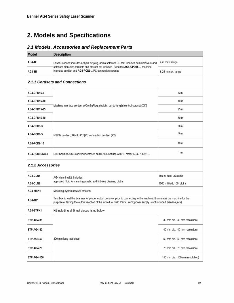
2. Models and Specifications
2.1 Models, Accessories and Replacement Parts
Model Description
AG4-4E Laser Scanner; includes a 9-pin X2 plug, and a software CD that includes both hardware and
software manuals; cordsets and bracket not included. Requires AG4-CPD15-.. machine
interface cordset and AG4-PCD9-.. PC connection cordset.
4 m max. range
AG4-6E 6.25 m max. range
2.1.1 Cordsets and Connections
AG4-CPD15-5
Machine interface cordset w/ConfigPlug, straight, cut-to-length [control cordset (X1)]
5 m
AG4-CPD15-10 10 m
AG4-CPD15-25 25 m
AG4-CPD15-50 50 m
AG4-PCD9-3
RS232 cordset, AG4 to PC [PC connection cordset (X2)]
3 m
AG4-PCD9-5 5 m
AG4-PCD9-10 10 m
AG4-PCD9USB-1 DB9 Serial-to-USB converter cordset. NOTE: Do not use with 10 meter AG4-PCD9-10. 1 m
2.1.2 Accessories
AG4-CLN1 AG4 cleaning kit, includes:
approved fluid for cleaning plastic, soft lint-free cleaning cloths
150 ml fluid, 25 cloths
AG4-CLN2 1000 ml fluid, 100 cloths
AG4-MBK1 Mounting system (swivel bracket)
AG4-TB1 Test box to test the Scanner for proper output behavior prior to connecting to the machine. It simulates the machine for the
purpose of testing the output reaction of the individual Field Pairs. 24 V; power supply is not included (banana jack).
AG4-STPK1 Kit including all 5 test pieces listed below
STP-AG4-30
300 mm long test piece
30 mm dia. (30 mm resolution)
STP-AG4-40 40 mm dia. (40 mm resolution)
STP-AG4-50 50 mm dia. (50 mm resolution)
STP-AG4-70 70 mm dia. (70 mm resolution)
STP-AG4-150 150 mm dia. (150 mm resolution)
Banner AG4 Series Safety Laser Scanner
20 P/N 144924 rev. A 02/2010 AG4 Safety Laser Scanner User Manual
2.1.3 Replacement Parts
AG4-WIN1 Window with seal for AG4 Laser Scanner
AG4- CPD15 Straight Config plug (connector), 15 pin, for AG4 auto-configuration
AG4-PCD9 Straight plug (connector) and dust plug, 9 pin AG4 for X2 interface
AG4A-SW-A Configuration and diagnostics software, AG4soft ( Windows 95/98/2000/NT/XP)
2.2 Specifications
Supply Voltage (UB)
24V dc (+20% / -30%)
Power supply in acc. with IEC 742 with safe supply isolation and compensation with voltage dips of up to 20 ms in
acc. with EN 61496-1.
Over-current protection: Via 1.6 A fuse melting fuse in the cabinet (see below)
Over-voltage protection: Over-voltage protection with safe limit stop
Protective earth conductor: Connection not permitted
Supply Current Approx. 420 mA, exclusive of load (use 2.5 A power supply)
Fuse (Power Supply) 1.6A normal blow, medium time lag fuse (user-supplied)
Response Time Min. 80 milliseconds (2 scans); Max. 640 milliseconds (16 scans) ; see Section 4.9 for more information
Wavelength 905 nm
Protection Field Radius (Sensing Range)
Model AG4-4E
150 mm resolution: 200 mm to 4.0 m
70 mm resolution: 200 mm to 4.0 m
50 mm resolution: 200 mm to 2.8 m
40 mm resolution: 200 mm to 2.2 m
30 mm resolution: 200 mm to 1.6 m
Sensing object reflectance: Minimum 1.8%
Model AG4-6E
150 mm resolution: 200 mm to 6.25 m
70 mm resolution: 200 mm to 6.25 m
50 mm resolution: 200 mm to 2.8 m
40 mm resolution: 200 mm to 2.2 m
30 mm resolution: 200 mm to 1.6 m Sensing object reflectance: Minimum 1.8%
Warning Field Resolution: 150 mm (at 15 m)
Sensing range (radius): 200 mm to 15 m
Sensing object reflectance: Minimum 20%
Monitored area 0-50 m
Scanning Angle max. 190°
Output Signal Switching Devices
(OSSD1, OSSD 2)
PNP open-collector transistor 2 outputs: short circuit proofed Rated operating voltage: supply voltage (UB) -3.2 V Max. source current: 250 mA Residual voltage: 3.2 V or less Operation mode: No object in protective field: ON Object inside protective field: OFF Response Time: Min. 80 ms (2 scans) to max. 640 milliseconds (16 scans) switching method
Banner AG4 Series Safety Laser Scanner
Banner AG4 Series User Manual P/N 144924 rev. A 02/2010 21
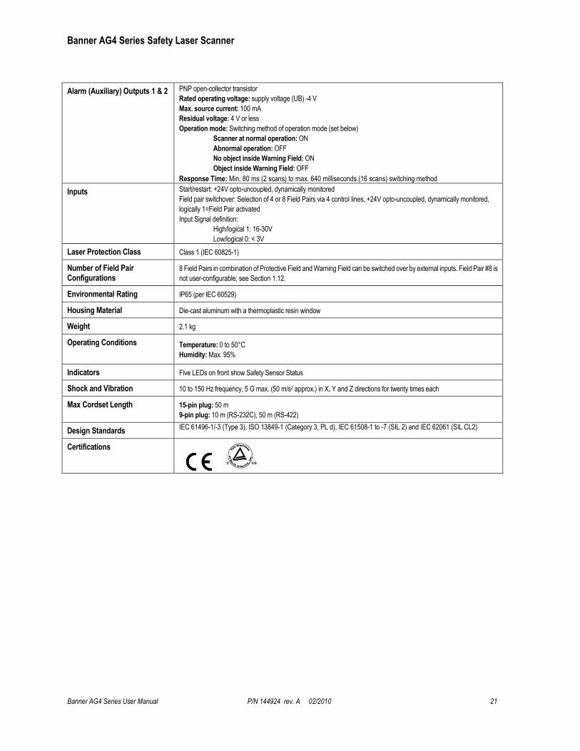
Alarm (Auxiliary) Outputs 1 & 2 PNP open-collector transistor
Rated operating voltage: supply voltage (UB) -4 V
Max. source current: 100 mA
Residual voltage: 4 V or less
Operation mode: Switching method of operation mode (set below)
Scanner at normal operation: ON
Abnormal operation: OFF
No object inside Warning Field: ON
Object inside Warning Field: OFF
Response Time: Min. 80 ms (2 scans) to max. 640 milliseconds (16 scans) switching method
Inputs Start/restart: +24V opto-uncoupled, dynamically monitored
Field pair switchover: Selection of 4 or 8 Field Pairs via 4 control lines, +24V opto-uncoupled, dynamically monitored,
logically 1=Field Pair activated
Input Signal definition:
High/logical 1: 16-30V
Low/logical 0: < 3V
Laser Protection Class Class 1 (IEC 60825-1)
Number of Field Pair Configurations
8 Field Pairs in combination of Protective Field and Warning Field can be switched over by external inputs. Field Pair #8 is
not user-configurable; see Section 1.12.
Environmental Rating IP65 (per IEC 60529)
Housing Material Die-cast aluminum with a thermoplastic resin window
Weight 2.1 kg
Operating Conditions Temperature: 0 to 50°C
Humidity: Max. 95%
Indicators Five LEDs on front show Safety Sensor Status
Shock and Vibration 10 to 150 Hz frequency, 5 G max. (50 m/s2 approx.) in X, Y and Z directions for twenty times each
Max Cordset Length 15-pin plug: 50 m
9-pin plug: 10 m (RS-232C), 50 m (RS-422)
Design Standards IEC 61496-1/-3 (Type 3), ISO 13849-1 (Category 3, PL d), IEC 61508-1 to -7 (SIL 2) and IEC 62061 (SIL CL2)
Certifications
Banner AG4 Series Safety Laser Scanner
22 P/N 144924 rev. A 02/2010 AG4 Safety Laser Scanner User Manual
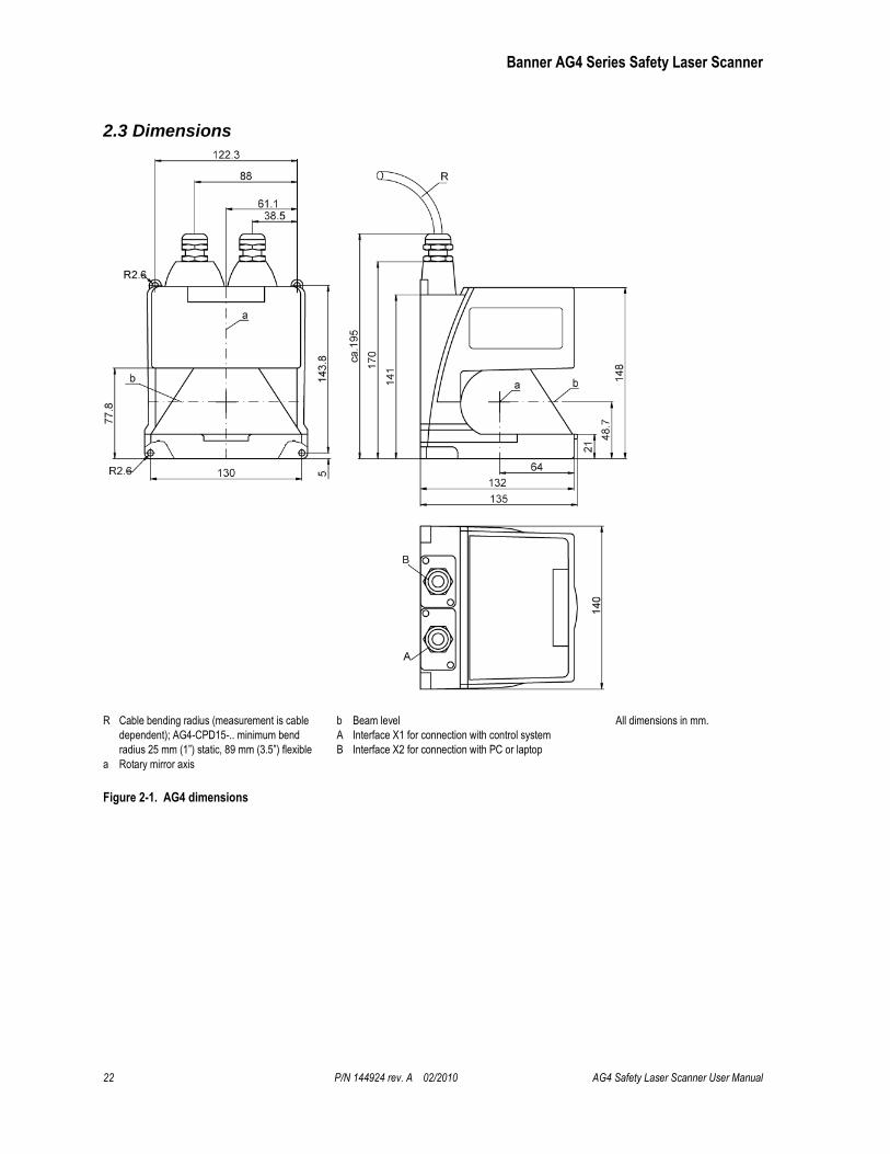
2.3 Dimensions
R Cable bending radius (measurement is cable
dependent); AG4-CPD15-.. minimum bend
radius 25 mm (1”) static, 89 mm (3.5”) flexible
a Rotary mirror axis
b Beam level
A Interface X1 for connection with control system
B Interface X2 for connection with PC or laptop
All dimensions in mm.
Figure 2-1. AG4 dimensions
Banner AG4 Series Safety Laser Scanner
Banner AG4 Series User Manual P/N 144924 rev. A 02/2010 23
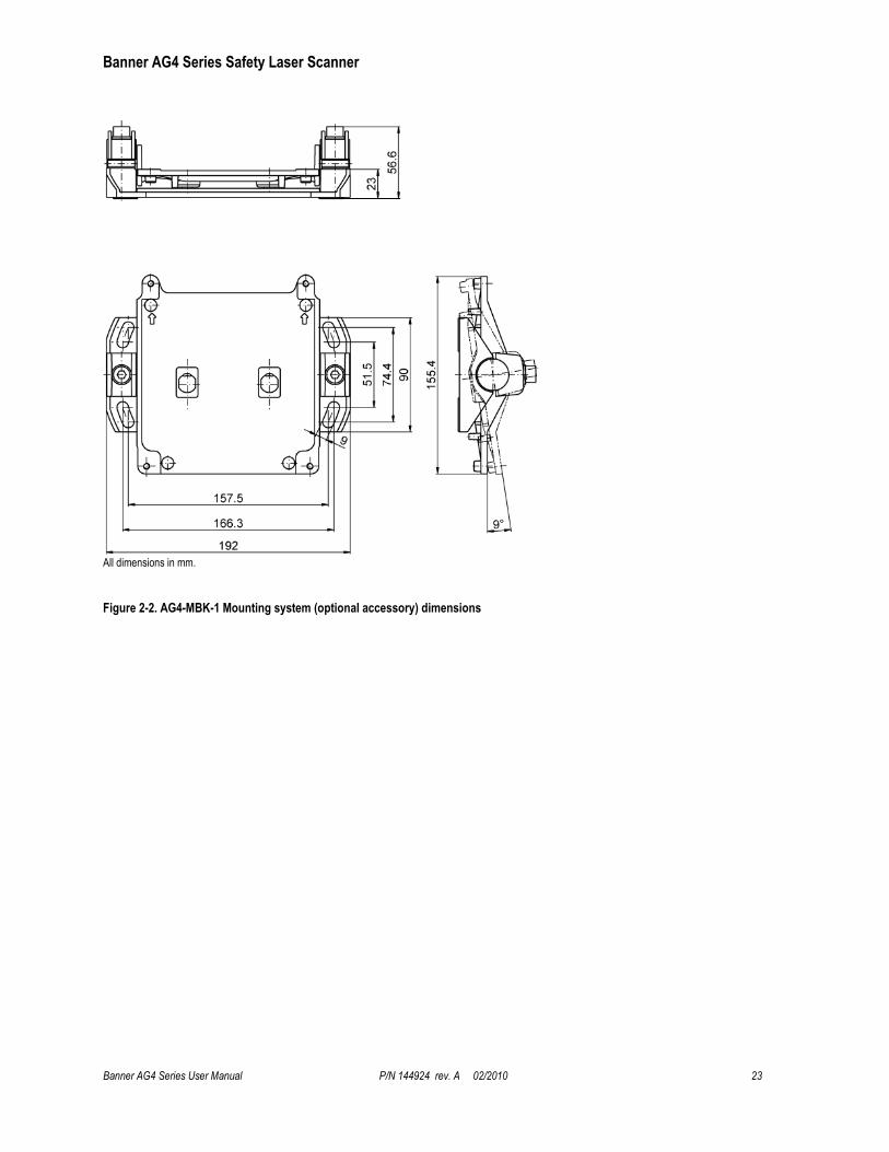
All dimensions in mm.
Figure 2-2. AG4-MBK-1 Mounting system (optional accessory) dimensions
Banner AG4 Series Safety Laser Scanner
24 P/N 144924 rev. A 02/2010 AG4 Safety Laser Scanner User Manual
2.4 Connector Plug Assignments
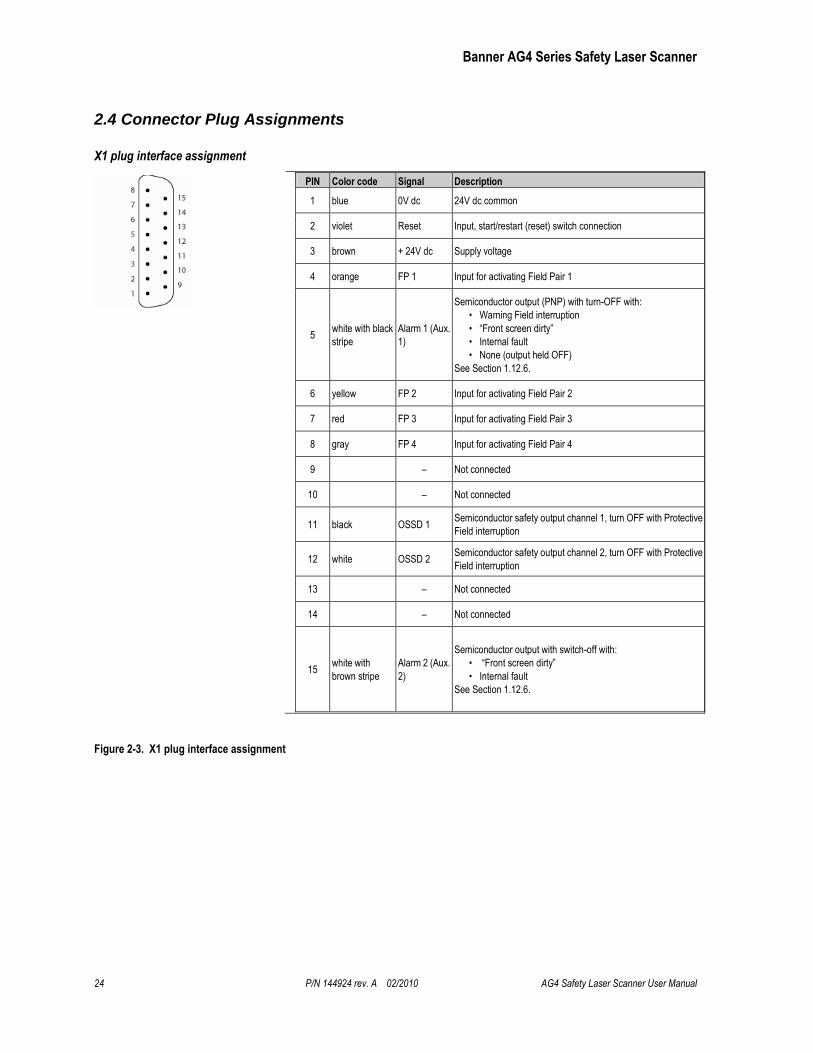
X1 plug interface assignment
PIN Color code Signal Description
1 blue 0V dc 24V dc common
2 violet Reset Input, start/restart (reset) switch connection
3 brown + 24V dc Supply voltage
4 orange FP 1 Input for activating Field Pair 1
5 white with black
stripe
Alarm 1 (Aux.
1)
Semiconductor output (PNP) with turn-OFF with:
• Warning Field interruption
• “Front screen dirty”
• Internal fault
• None (output held OFF)
See Section 1.12.6.
6 yellow FP 2 Input for activating Field Pair 2
7 red FP 3 Input for activating Field Pair 3
8 gray FP 4 Input for activating Field Pair 4
9 – Not connected
10 – Not connected
11 black OSSD 1 Semiconductor safety output channel 1, turn OFF with Protective
Field interruption
12 white OSSD 2 Semiconductor safety output channel 2, turn OFF with Protective
Field interruption
13 – Not connected
14 – Not connected
15 white with
brown stripe
Alarm 2 (Aux.
2)
Semiconductor output with switch-off with:
• “Front screen dirty”
• Internal fault
See Section 1.12.6.
Figure 2-3. X1 plug interface assignment
Banner AG4 Series Safety Laser Scanner
Banner AG4 Series User Manual P/N 144924 rev. A 02/2010 25
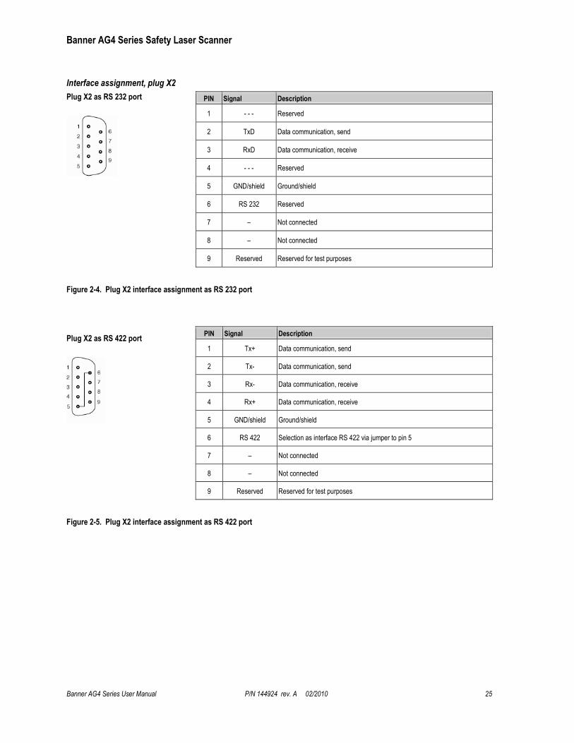
Interface assignment, plug X2
Plug X2 as RS 232 port
PIN Signal Description
1 - - - Reserved
2 TxD Data communication, send
3 RxD Data communication, receive
4 - - - Reserved
5 GND/shield Ground/shield
6 RS 232 Reserved
7 – Not connected
8 – Not connected
9 Reserved Reserved for test purposes
Figure 2-4. Plug X2 interface assignment as RS 232 port
Plug X2 as RS 422 port
PIN Signal Description
1 Tx+ Data communication, send
2 Tx- Data communication, send
3 Rx- Data communication, receive
4 Rx+ Data communication, receive
5 GND/shield Ground/shield
6 RS 422 Selection as interface RS 422 via jumper to pin 5
7 – Not connected
8 – Not connected
9 Reserved Reserved for test purposes
Figure 2-5. Plug X2 interface assignment as RS 422 port

Banner AG4 Series Safety Laser Scanner
26 P/N 144924 rev. A 02/2010 AG4 Safety Laser Scanner User Manual
3. Installation
Before installing the Scanner, read Sections 1 and 3 of this manual in their entirety. The System’s ability to
perform its safety guarding function depends upon the appropriateness of the application and upon its proper mechanical and electrical installation and interfacing to the guarded machine. A risk assessment must determine if the application of the Scanner is appropriate, which includes the AG4 software configuration and the Protective and Warning Field coverage.
If all mounting, installation, interfacing, and checkout procedures are not followed properly, the System cannot provide the protection for which it was designed. Installation must be performed by a Qualified Person, as defined in Section 4.1. See Warning below.
WARNING . . . READ THIS SECTION CAREFULLY BEFORE INSTALLING THE SYSTEM
The user is responsible for satisfying all local, state, and national codes and regulations relating to the installation and use of this
control system in any particular application. Take extreme care to meet all legal requirements and follow all technical installation
and maintenance instructions contained in this manual.
The user has the sole responsibility to ensure that the Scanner is installed and interfaced to the guarded machine by Qualified
Persons in accordance with this manual and with applicable safety regulations.
Read Section 1 and all of Section 3 of this manual carefully before installing the System. Failure to follow these instructions could
result in serious bodily injury or death.
Banner AG4 Series Safety Laser Scanner
Banner AG4 Series User Manual P/N 144924 rev. A 02/2010 27
3.1 Basic Installation Procedure
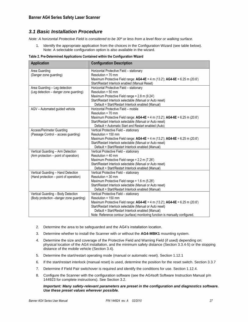
Note: A horizontal Protective Field is considered to be 30º or less from a level floor or walking surface.
1. Identify the appropriate application from the choices in the Configuration Wizard (see table below). Note: A selectable configuration option is also available in the wizard.
Table 2. Pre-Determined Applications Contained within the Configuration Wizard
Application Configuration Description
Area Guarding (Danger zone guarding)
Horizontal Protective Field – stationary Resolution = 70 mm Maximum Protective Field range: AG4-4E = 4 m (13.2'); AG4-6E = 6.25 m (20.6') Start/Restart Interlock enabled (Manual Reset)
Area Guarding – Leg detection (Leg detection – danger zone guarding)
Horizontal Protective Field – stationary Resolution = 50 mm Maximum Protective Field range = 2.8 m (9.24') Start/Restart Interlock selectable (Manual or Auto reset) Default = Start/Restart Interlock enabled (Manual)
AGV – Automated guided vehicle
Horizontal Protective Field – mobile Resolution = 70 mm Maximum Protective Field range: AG4-4E = 4 m (13.2'); AG4-6E = 6.25 m (20.6') Start/Restart Interlock selectable (Manual or Auto reset) Default = Automatic Start and Restart enabled (Auto)
Access/Perimeter Guarding (Passage Control – access guarding)
Vertical Protective Field – stationary Resolution = 150 mm Maximum Protective Field range: AG4-4E = 4 m (13.2'); AG4-6E = 6.25 m (20.6') Start/Restart Interlock selectable (Manual or Auto reset) Default = Start/Restart Interlock enabled (Manual)
Vertical Guarding – Arm Detection (Arm protection – point of operation)
Vertical Protective Field – stationary Resolution = 40 mm Maximum Protective Field range = 2.2 m (7.26') Start/Restart Interlock selectable (Manual or Auto reset) Default = Start/Restart Interlock enabled (Manual)
Vertical Guarding – Hand Detection (Hand protection – point of operation)
Vertical Protective Field – stationary Resolution = 30 mm Maximum Protective Field range = 1.6 m (5.28') Start/Restart Interlock selectable (Manual or Auto reset) Default = Start/Restart Interlock enabled (Manual)
Vertical Guarding – Body Detection (Body protection –danger zone guarding)
Vertical Protective Field – stationary Resolution = 150 mm Maximum Protective Field range: AG4-4E = 4 m (13.2'); AG4-6E = 6.25 m (20.6') Start/Restart Interlock selectable (Manual or Auto reset) Default = Start/Restart Interlock enabled (Manual) Note: Reference contour (surface) monitoring function is manually configured.
2. Determine the area to be safeguarded and the AG4’s installation location.
3. Determine whether to install the Scanner with or without the AG4-MBK1 mounting system.
4. Determine the size and coverage of the Protective Field and Warning Field (if used) depending on: physical location of the AG4 installation, and the minimum safety distance (Section 3.3.4-5) or the stopping distance of the mobile vehicle (Section 3.4).
5. Determine the start/restart operating mode (manual or automatic reset). Section 1.12.1
6. If the start/restart interlock (manual reset) is used, determine the position for the reset switch. Section 3.3.7
7. Determine if Field Pair switchover is required and identify the conditions for use. Section 1.12.4.
8. Configure the Scanner with the configuration software (see the AG4soft Software Instruction Manual p/n 144923 for complete instructions). See Section 3.2.
Important: Many safety-relevant parameters are preset in the configuration and diagnostics software. Use these preset values wherever possible.

Banner AG4 Series Safety Laser Scanner
28 P/N 144924 rev. A 02/2010 AG4 Safety Laser Scanner User Manual
9. Record the Scanner configuration and Protective/Warning Fields dimensioning. This document should identify and be signed by the individual(s) responsible for the configuration, and be included with the machine documentation (see the AG4soft Software Instruction Manual for more information on configuration
documentation).
10. For stationary application, it is recommended to mark the perimeter of the Protective Field(s) on the floor as an awareness means for individuals in the area. For mobile applications, it is recommended that the diagram be readily available for review.
11. If required, install means to protect the Scanner from physical damage, sources of optical interference (e.g., other Scanners), or prevent the Scanner from being used as a climbing aid. Ensure that these means do not impair the field of view.
NOTE: See AG4 Series Safety Laser Scanner Application Guide (P/N 147900) for application check list items and application examples.
3.2 Protective Field and Warning Field Considerations
Ensure the dimension (size) and coverage of the Protective Field can detect an intrusion and allow the Scanner’s OSSDs to stop the dangerous movement before personnel can access the hazard. (See safety distance, Section 3.3.4-3.3.5, and stopping distance Section 3.4.)
Ensure that access to all hazards is not possible for all Field Pair switchover applications (see Section 1.12.4).
Protective Fields with a range of less than 200 mm are not permitted.
Ensure that safety distance and stopping distance calculations incorporate all factors that can effect response time, including:
The additive effect of all device response times, such as the Scanner, UM-FA-… safety module, and all control elements (FSDs and/or MPCEs).
Add the appropriate response time values to account for any reasonably foreseeable machine stop time degradation, such as due to brake pad wear.
Ensure that the Protective Field adequately covers all access routes that may lead to the safeguarded hazard, or supplemental guarding may be required (see Unmonitored Areas Section 3.3.1).
Determine if a reference contour (surface) monitoring function is required (especially in vertical Protective Field applications). This function prevents unintentional misalignment and deliberate manipulation of the Scanner. See Section 1.12.5.
Ensure that the safeguarded hazard(s) cannot be accessed because of the effect of ―shadowing‖ within the Protective Field by adding supplemental safeguarding, such as additional Scanners. See Section 3.1.1.
Observe the lateral tolerance when dimensioning the Protective Fields, (e.g., do not use needle or cone-shaped boundaries to define the separation (safety) distance; cone-shaped boundaries rely on less accurate, angular resolution measurements). See Section 3.3.2.
Consider and resolve any other application factors that might require an increase in the separation (safety) distance or stopping distance. These factors should be identified via the risk assessment process.
Banner AG4 Series Safety Laser Scanner
Banner AG4 Series User Manual P/N 144924 rev. A 02/2010 29
3.3 Mechanical Installation Considerations
Many factors influence the layout of the Scanner’s mechanical installation. For stationary applications, these include separation (safety) distance, supplemental safeguarding (hard guarding), unmonitored areas (shadows or areas behind the Scanner), adjacent Scanners, and the height of the Protective Field (in horizontal applications). In addition, mobile applications must take into account the stopping performance and distance of the mobile vehicle which the Scanner is controlling.
3.3.1 Unmonitored Areas
WARNING . . . UNMONITORED AREAS
The area behind the Scanner and near it, on either side (shown in the following figure) is not monitored. Unmonitored areas can create an access
route to the hazard or a blind zone where a person cannot be detected. Make sure that this unmonitored area is minimized, so that no one can
access this area undetected (by recessing the Scanner into the machine, using supplemental safeguarding, or using mechanical barriers to
prevent access). Failure to do so could result in serious bodily injury or death.
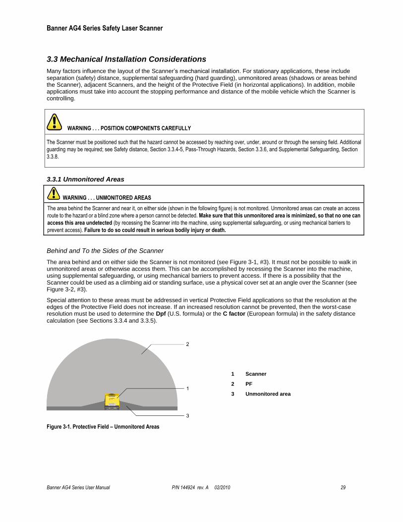
Behind and To the Sides of the Scanner
The area behind and on either side the Scanner is not monitored (see Figure 3-1, #3). It must not be possible to walk in unmonitored areas or otherwise access them. This can be accomplished by recessing the Scanner into the machine, using supplemental safeguarding, or using mechanical barriers to prevent access. If there is a possibility that the Scanner could be used as a climbing aid or standing surface, use a physical cover set at an angle over the Scanner (see Figure 3-2, #3).
Special attention to these areas must be addressed in vertical Protective Field applications so that the resolution at the edges of the Protective Field does not increase. If an increased resolution cannot be prevented, then the worst-case resolution must be used to determine the Dpf (U.S. formula) or the C factor (European formula) in the safety distance
calculation (see Sections 3.3.4 and 3.3.5).
1 Scanner
2 PF
3 Unmonitored area
Figure 3-1. Protective Field – Unmonitored Areas
WARNING . . . POSITION COMPONENTS CAREFULLY
The Scanner must be positioned such that the hazard cannot be accessed by reaching over, under, around or through the sensing field. Additional
guarding may be required; see Safety distance, Section 3.3.4-5, Pass-Through Hazards, Section 3.3.6, and Supplemental Safeguarding, Section
3.3.8.
Banner AG4 Series Safety Laser Scanner
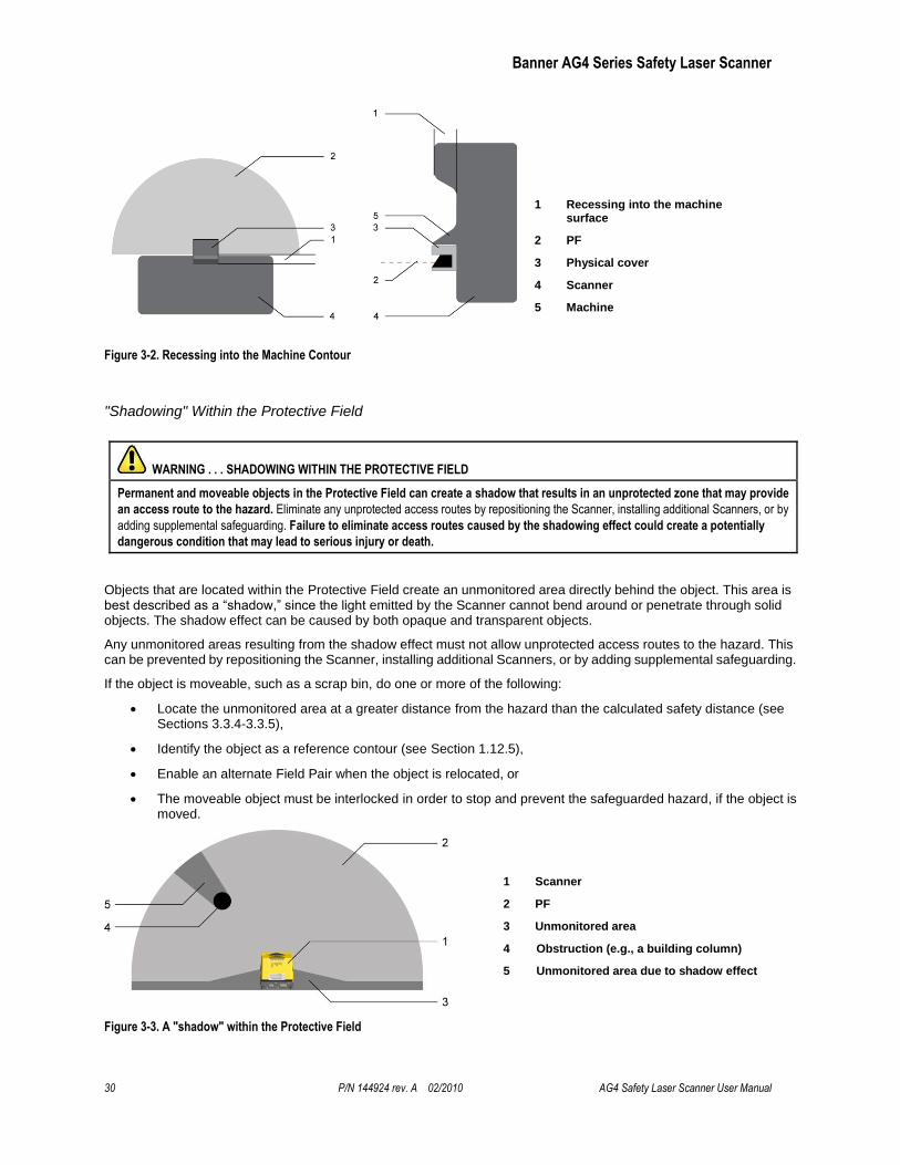
30 P/N 144924 rev. A 02/2010 AG4 Safety Laser Scanner User Manual
1 Recessing into the machine surface
2 PF
3 Physical cover
4 Scanner
5 Machine
Figure 3-2. Recessing into the Machine Contour
"Shadowing" Within the Protective Field
WARNING . . . SHADOWING WITHIN THE PROTECTIVE FIELD
Permanent and moveable objects in the Protective Field can create a shadow that results in an unprotected zone that may provide
an access route to the hazard. Eliminate any unprotected access routes by repositioning the Scanner, installing additional Scanners, or by
adding supplemental safeguarding. Failure to eliminate access routes caused by the shadowing effect could create a potentially
dangerous condition that may lead to serious injury or death.
Objects that are located within the Protective Field create an unmonitored area directly behind the object. This area is best described as a ―shadow,‖ since the light emitted by the Scanner cannot bend around or penetrate through solid objects. The shadow effect can be caused by both opaque and transparent objects.
Any unmonitored areas resulting from the shadow effect must not allow unprotected access routes to the hazard. This can be prevented by repositioning the Scanner, installing additional Scanners, or by adding supplemental safeguarding.
If the object is moveable, such as a scrap bin, do one or more of the following:
Locate the unmonitored area at a greater distance from the hazard than the calculated safety distance (see Sections 3.3.4-3.3.5),
Identify the object as a reference contour (see Section 1.12.5),
Enable an alternate Field Pair when the object is relocated, or
The moveable object must be interlocked in order to stop and prevent the safeguarded hazard, if the object is moved.
1 Scanner
2 PF
3 Unmonitored area
4 Obstruction (e.g., a building column)
5 Unmonitored area due to shadow effect
Figure 3-3. A "shadow" within the Protective Field
Banner AG4 Series Safety Laser Scanner
Banner AG4 Series User Manual P/N 144924 rev. A 02/2010 31
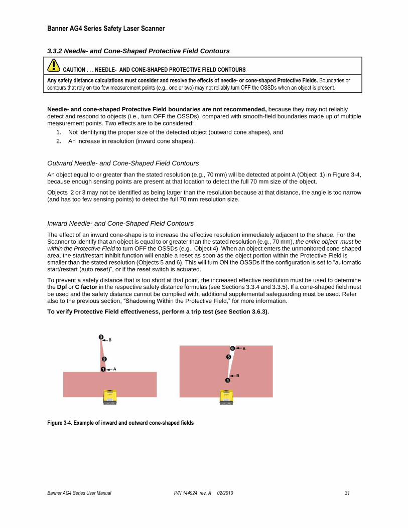
3.3.2 Needle- and Cone-Shaped Protective Field Contours
CAUTION . . . NEEDLE- AND CONE-SHAPED PROTECTIVE FIELD CONTOURS
Any safety distance calculations must consider and resolve the effects of needle- or cone-shaped Protective Fields. Boundaries or
contours that rely on too few measurement points (e.g., one or two) may not reliably turn OFF the OSSDs when an object is present.
Needle- and cone-shaped Protective Field boundaries are not recommended, because they may not reliably
detect and respond to objects (i.e., turn OFF the OSSDs), compared with smooth-field boundaries made up of multiple measurement points. Two effects are to be considered:
1. Not identifying the proper size of the detected object (outward cone shapes), and
2. An increase in resolution (inward cone shapes).
Outward Needle- and Cone-Shaped Field Contours
An object equal to or greater than the stated resolution (e.g., 70 mm) will be detected at point A (Object 1) in Figure 3-4, because enough sensing points are present at that location to detect the full 70 mm size of the object.
Objects 2 or 3 may not be identified as being larger than the resolution because at that distance, the angle is too narrow (and has too few sensing points) to detect the full 70 mm resolution size.
Inward Needle- and Cone-Shaped Field Contours
The effect of an inward cone-shape is to increase the effective resolution immediately adjacent to the shape. For the Scanner to identify that an object is equal to or greater than the stated resolution (e.g., 70 mm), the entire object must be within the Protective Field to turn OFF the OSSDs (e.g., Object 4). When an object enters the unmonitored cone-shaped area, the start/restart inhibit function will enable a reset as soon as the object portion within the Protective Field is smaller than the stated resolution (Objects 5 and 6). This will turn ON the OSSDs if the configuration is set to ―automatic start/restart (auto reset)‖, or if the reset switch is actuated.
To prevent a safety distance that is too short at that point, the increased effective resolution must be used to determine the Dpf or C factor in the respective safety distance formulas (see Sections 3.3.4 and 3.3.5). If a cone-shaped field must
be used and the safety distance cannot be complied with, additional supplemental safeguarding must be used. Refer also to the previous section, ―Shadowing Within the Protective Field,‖ for more information.
To verify Protective Field effectiveness, perform a trip test (see Section 3.6.3).
Figure 3-4. Example of inward and outward cone-shaped fields
Banner AG4 Series Safety Laser Scanner
32 P/N 144924 rev. A 02/2010 AG4 Safety Laser Scanner User Manual
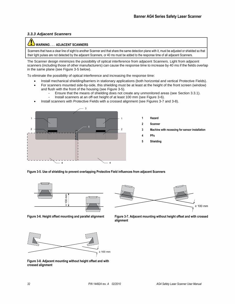
3.3.3 Adjacent Scanners
WARNING . . . ADJACENT SCANNERS
Scanners that have a clear line of sight to another Scanner and that share the same detection plane with it, must be adjusted or shielded so that
their light pulses are not detected by the adjacent Scanners, or 40 ms must be added to the response time of all adjacent Scanners.
The Scanner design minimizes the possibility of optical interference from adjacent Scanners. Light from adjacent scanners (including those of other manufacturers) can cause the response time to increase by 40 ms if the fields overlap in the same plane (see Figure 3-5 below).
To eliminate the possibility of optical interference and increasing the response time:
Install mechanical shielding/barriers in stationary applications (both horizontal and vertical Protective Fields).
For scanners mounted side-by-side, this shielding must be at least at the height of the front screen (window) and flush with the front of the housing (see Figure 3-5).
Ensure that the means of shielding does not create any unmonitored areas (see Section 3.3.1). Install scanners at an off-set height of at least 100 mm (see Figure 3-6).
Install scanners with Protective Fields with a crossed alignment (see Figures 3-7 and 3-8).
1 Hazard
2 Scanner
3 Machine with recessing for sensor installation
4 PFs
5 Shielding
Figure 3-5. Use of shielding to prevent overlapping Protective Field influences from adjacent Scanners
Figure 3-6. Height offset mounting and parallel alignment Figure 3-7. Adjacent mounting without height offset and with crossed alignment
Figure 3-8. Adjacent mounting without height offset and with crossed alignment
Banner AG4 Series Safety Laser Scanner
Banner AG4 Series User Manual P/N 144924 rev. A 02/2010 33
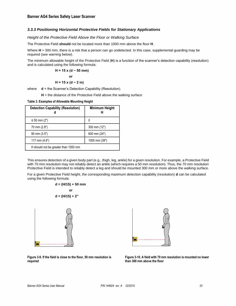
3.3.3 Positioning Horizontal Protective Fields for Stationary Applications
Height of the Protective Field Above the Floor or Walking Surface
The Protective Field should not be located more than 1000 mm above the floor H.
Where H > 300 mm, there is a risk that a person can go undetected. In this case, supplemental guarding may be
required (see warning below).
The minimum allowable height of the Protective Field (H) is a function of the scanner’s detection capability (resolution)
and is calculated using the following formula:
H = 15 x (d − 50 mm)
or
H = 15 x (d − 2 in)
where d = the Scanner’s Detection Capability (Resolution).
H = the distance of the Protective Field above the walking surface
Table 3. Examples of Allowable Mounting Height
Detection Capability (Resolution) d
Minimum Height H
≤ 50 mm (2") 0
70 mm (2.8") 300 mm (12")
90 mm (3.5") 600 mm (24")
117 mm (4.6") 1000 mm (39")
H should not be greater than 1000 mm
This ensures detection of a given body part (e.g., thigh, leg, ankle) for a given resolution. For example, a Protective Field with 70 mm resolution may not reliably detect an ankle (which requires a 50 mm resolution). Thus, the 70 mm resolution Protective Field is intended to reliably detect a leg and should be mounted 300 mm or more above the walking surface.
For a given Protective Field height, the corresponding maximum detection capability (resolution) d can be calculated
using the following formula:
d = (H/15) + 50 mm
or
d = (H/15) + 2"
Figure 3-9. If the field is close to the floor, 50 mm resolution is required
Figure 3-10. A field with 70 mm resolution is mounted no lower than 300 mm above the floor
Banner AG4 Series Safety Laser Scanner
34 P/N 144924 rev. A 02/2010 AG4 Safety Laser Scanner User Manual
WARNING . . . PROTECTIVE FIELD HEIGHT (STATIONARY HORIZONTAL FIELDS)
Where the height of a horizontal Protective Field is H > 300 mm, there is a risk that a person can go undetected beneath the field. If it is possible
for an individual to crawl undetected under the Protective Field and access the hazard, install supplemental guarding to prevent this access.
3.3.4 Minimum Safety (Separation) Distance – Stationary Applications (US Standards)
Response Time Considerations
The Scanner’s mirror rotates every 40 ms (25 scans [revolutions] per second). The safety outputs will switch off only after an object is detected in the Protective Field for at least two consecutive scans. The Scanner’s minimum response time is therefore 80 ms (2x 40ms).
To increase the Scanner’s reliability in an adverse environments (e.g., with fine airborne particles), increase the number of scans required before the scanners safety outputs turn off. With each additional scan the response time (Tr) increases by 40 ms. With K = 1600 mm/s the separation (safety) distance increases by 64 mm (40 ms x 1600 mm/s) per
additional scan.
WARNING . . . SCANNER RESPONSE TIME ADJUSTMENTS
Do not increase the Scanner’s 80 ms response time for vertically positioned Protective Fields such as work cell access (Entry/ Exit) or
perimeter guarding applications where a person could move quickly through the Protective Field without being detected.
Failure to follow this recommendation could result in serious bodily injury or death.
Minimum Safety (Separation) Distance Formula
When all factors that influence the Safety Distance are considered, the formula is:
DS = [K x (TS + TR)] + Dpf + ZSM + Zrefl
where
DS = the safety distance, in mm (inches);
K = 1600 mm per second (63 inches per second) (see note 1 below)
TS = maximum stopping time (sec) of the machine (see note 2 below)
TR = maximum response time (sec) of the Scanner (see note 3 below)
Dpf = Depth penetration factor: The additional distance required by U.S. standards, such as ANSI B11.19, to
prevent a person from encroaching towards the hazard without being detected.
ZSM = the additional distance needed to account for distance measurement error.
Zrefl = the additional distance needed to account for error due to reflections from retro reflective surfaces.
Notes
1. The OSHA-recommended hand speed constant K has been determined by various studies, and although these studies indicate speeds of 1600 mm/s (63‖/s) to more than 2540 mm/s (100‖/s), they are not conclusive determinations. Consider all factors, including the physical ability of the operator, when determining the value of K to be used.
2. TS is usually measured by a stop-time measuring device. If the machine manufacturer’s specified stop time is used, add at least 20% to allow for possible clutch/brake system deterioration. This measurement must take into account the slower of the two MPCE channels, and the response time of all devices or controls that react to stop the machine (e.g., UM-FA-9A safety module). See Notice Regarding MPCEs. If all devices are not included, the calculated safety distance (Ds) will be too short and serious injury could result.
3. Consideration for Adjacent Scanners. When adjacent Scanner share the same detection plane and have an unobstructed view of each other, an additional 40 ms time must be added to the response times of both scanners. If the adjacent scanners’ detection planes are shielded so that there is no clear line of sight between sensors or there is at least a 4" (100 mm) detection plane offset, then the 40 ms addition is not required.
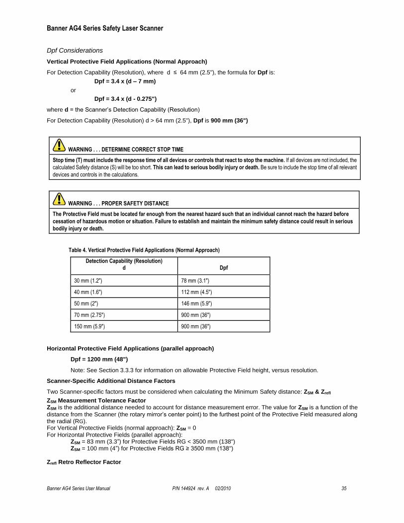
Banner AG4 Series Safety Laser Scanner
Banner AG4 Series User Manual P/N 144924 rev. A 02/2010 35
Dpf Considerations
Vertical Protective Field Applications (Normal Approach)
For Detection Capability (Resolution), where d ≤ 64 mm (2.5"), the formula for Dpf is:
Dpf = 3.4 x (d – 7 mm)
or
Dpf = 3.4 x (d - 0.275")
where d = the Scanner’s Detection Capability (Resolution)
For Detection Capability (Resolution) d > 64 mm (2.5"), Dpf is 900 mm (36")
WARNING . . . DETERMINE CORRECT STOP TIME
Stop time (T) must include the response time of all devices or controls that react to stop the machine. If all devices are not included, the
calculated Safety distance (S) will be too short. This can lead to serious bodily injury or death. Be sure to include the stop time of all relevant
devices and controls in the calculations.
WARNING . . . PROPER SAFETY DISTANCE
The Protective Field must be located far enough from the nearest hazard such that an individual cannot reach the hazard before
cessation of hazardous motion or situation. Failure to establish and maintain the minimum safety distance could result in serious
bodily injury or death.
Table 4. Vertical Protective Field Applications (Normal Approach)
Detection Capability (Resolution) d
Dpf
30 mm (1.2") 78 mm (3.1")
40 mm (1.6") 112 mm (4.5")
50 mm (2") 146 mm (5.9")
70 mm (2.75") 900 mm (36")
150 mm (5.9") 900 mm (36")
Horizontal Protective Field Applications (parallel approach)
Dpf = 1200 mm (48")
Note: See Section 3.3.3 for information on allowable Protective Field height, versus resolution.
Scanner-Specific Additional Distance Factors
Two Scanner-specific factors must be considered when calculating the Minimum Safety distance: ZSM & Zrefl
ZSM Measurement Tolerance Factor ZSM is the additional distance needed to account for distance measurement error. The value for ZSM is a function of the
distance from the Scanner (the rotary mirror’s center point) to the furthest point of the Protective Field measured along the radial (RG). For Vertical Protective Fields (normal approach): ZSM = 0
For Horizontal Protective Fields (parallel approach): ZSM = 83 mm (3.3‖) for Protective Fields RG < 3500 mm (138") ZSM = 100 mm (4‖) for Protective Fields RG ≥ 3500 mm (138")
Zrefl Retro Reflector Factor

Banner AG4 Series Safety Laser Scanner
36 P/N 144924 rev. A 02/2010 AG4 Safety Laser Scanner User Manual
Zrefl is the additional distance needed to account for error due to reflections from retro reflective or shiny surfaces that
are present in the scanning plane. No Retro-reflectors: Zrefl = 0 Retro-reflectors located within the scanning plane of the Protective Field: Zrefl = 100 mm (4")
3.3.5 Minimum Safety Distance – Stationary Applications (European Standards)
Response Time Considerations
The Scanner’s mirror rotates every 40 ms (25 scans – or revolutions – per second). The safety outputs will switch OFF only after an object is detected in the Protective Field for at least two consecutive scans. The Scanner’s minimum response time is therefore 80 ms (2 x 40 ms).
To increase the Scanner’s reliability in an adverse environments (e.g., with fine airborne particles), increase the number of scans required before the Scanner's safety outputs turn OFF. With each additional scan, the response time (t1) increases by 40 ms. With K = 1600 mm/s, the separation (safety) distance increases by 64 mm (40 ms x 1600 mm/s)
per additional scan.
WARNING . . . AG4 RESPONSE TIME ADJUSTMENTS
Do not increase the Scanner’s 80 ms response time for vertically positioned Protective Fields such as work cell access (Entry/ Exit) or perimeter
guarding applications where a person could move quickly through the Protective Field without being detected.
Failure to follow this recommendation could result in serious bodily injury or death.
WARNING . . . DETERMINE CORRECT STOP TIME
Stop time (T) must include the response time of all devices or controls that react to stop the machine. If all devices are not included, the
calculated Safety distance (S) will be too short. This can lead to serious bodily injury or death. Be sure to include the stop time of all relevant
devices and controls in the calculations.
WARNING . . . PROPER SAFETY DISTANCE
The Protective Field must be located far enough from the nearest hazard such that an individual cannot reach the hazard before
cessation of hazardous motion or situation. Failure to establish and maintain the minimum safety distance could result in serious
bodily injury or death.
Minimum Safety (Separation) Distance Formula
When all factors that influence the Safety distance are considered, the formula is:
S = (K x T) + C + ZSM + Zrefl
where
S = the minimum distance between the hazard and the Protective Field. S is never less than 100 mm (4‖).
K = approach speed (see note 1 below)
2000 mm per second (79" per second) for S < 500 mm (20‖)
1600 mm per second (63" per second) for S > 500 mm (20‖)
T = overall system stopping performance in seconds (see note 2 below)
C = an additional distance in millimeters (inches), based on intrusion towards the hazard prior to actuation of
the Scanner. This value is never less than zero.
ZSM = the additional distance needed to account for distance measurement error.
Zrefl = the additional distance needed to account for error due to reflections from retro reflective surfaces.
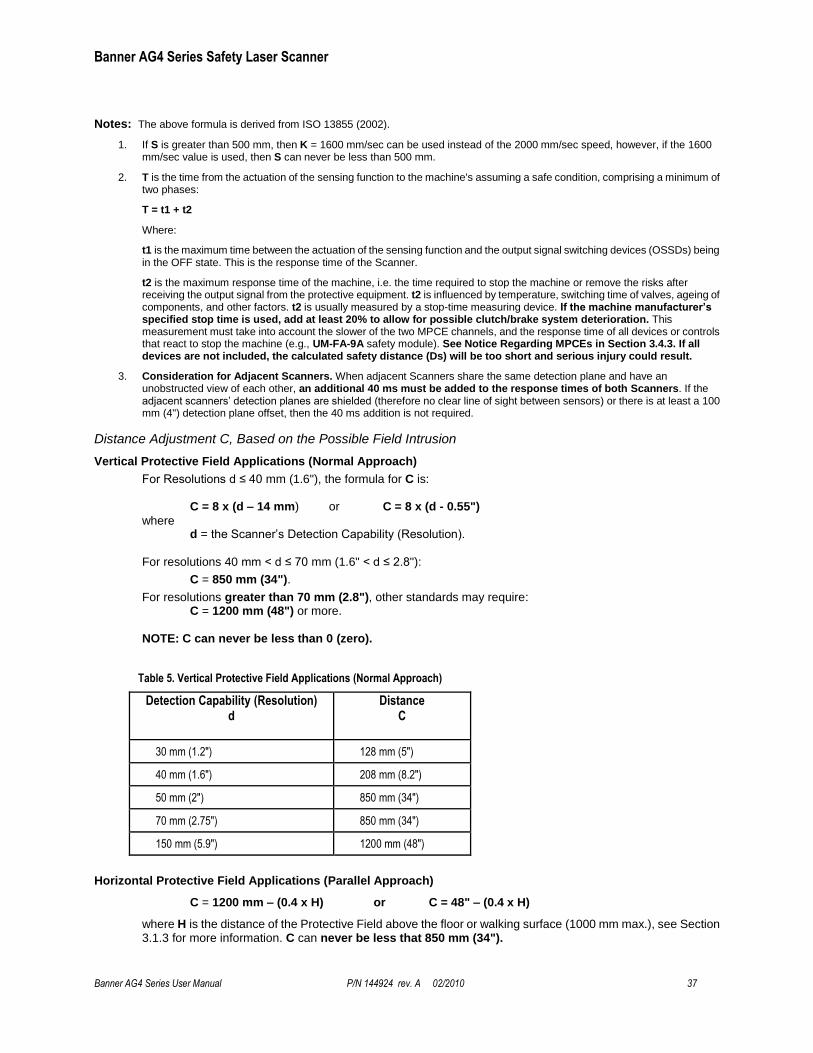
Banner AG4 Series Safety Laser Scanner
Banner AG4 Series User Manual P/N 144924 rev. A 02/2010 37
Notes: The above formula is derived from ISO 13855 (2002).
1. If S is greater than 500 mm, then K = 1600 mm/sec can be used instead of the 2000 mm/sec speed, however, if the 1600 mm/sec value is used, then S can never be less than 500 mm.
2. T is the time from the actuation of the sensing function to the machine's assuming a safe condition, comprising a minimum of two phases:
T = t1 + t2
Where:
t1 is the maximum time between the actuation of the sensing function and the output signal switching devices (OSSDs) being in the OFF state. This is the response time of the Scanner.
t2 is the maximum response time of the machine, i.e. the time required to stop the machine or remove the risks after receiving the output signal from the protective equipment. t2 is influenced by temperature, switching time of valves, ageing of components, and other factors. t2 is usually measured by a stop-time measuring device. If the machine manufacturer’s specified stop time is used, add at least 20% to allow for possible clutch/brake system deterioration. This measurement must take into account the slower of the two MPCE channels, and the response time of all devices or controls that react to stop the machine (e.g., UM-FA-9A safety module). See Notice Regarding MPCEs in Section 3.4.3. If all devices are not included, the calculated safety distance (Ds) will be too short and serious injury could result.
3. Consideration for Adjacent Scanners. When adjacent Scanners share the same detection plane and have an unobstructed view of each other, an additional 40 ms must be added to the response times of both Scanners. If the adjacent scanners’ detection planes are shielded (therefore no clear line of sight between sensors) or there is at least a 100 mm (4") detection plane offset, then the 40 ms addition is not required.
Distance Adjustment C, Based on the Possible Field Intrusion
Vertical Protective Field Applications (Normal Approach)
For Resolutions d ≤ 40 mm (1.6"), the formula for C is:
C = 8 x (d – 14 mm) or C = 8 x (d - 0.55")
where d = the Scanner’s Detection Capability (Resolution).
For resolutions 40 mm < d ≤ 70 mm (1.6" < d ≤ 2.8"):
C = 850 mm (34").
For resolutions greater than 70 mm (2.8"), other standards may require: C = 1200 mm (48") or more.
NOTE: C can never be less than 0 (zero).
Table 5. Vertical Protective Field Applications (Normal Approach)
Detection Capability (Resolution) d
Distance C
30 mm (1.2") 128 mm (5")
40 mm (1.6") 208 mm (8.2")
50 mm (2") 850 mm (34")
70 mm (2.75") 850 mm (34")
150 mm (5.9") 1200 mm (48")
Horizontal Protective Field Applications (Parallel Approach)
C = 1200 mm – (0.4 x H) or C = 48" – (0.4 x H)
where H is the distance of the Protective Field above the floor or walking surface (1000 mm max.), see Section 3.1.3 for more information. C can never be less that 850 mm (34").
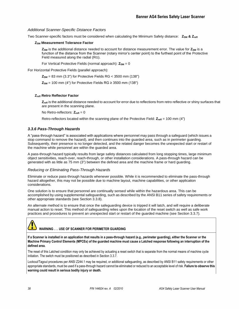
Banner AG4 Series Safety Laser Scanner
38 P/N 144924 rev. A 02/2010 AG4 Safety Laser Scanner User Manual
Additional Scanner-Specific Distance Factors
Two Scanner-specific factors must be considered when calculating the Minimum Safety distance: ZSM & Zrefl
ZSM Measurement Tolerance Factor
ZSM is the additional distance needed to account for distance measurement error. The value for ZSM is a
function of the distance from the Scanner (rotary mirror’s center point) to the furthest point of the Protective Field measured along the radial (RG).
For Vertical Protective Fields (normal approach): ZSM = 0
For Horizontal Protective Fields (parallel approach):
ZSM = 83 mm (3.3") for Protective Fields RG < 3500 mm (138")
ZSM = 100 mm (4") for Protective Fields RG ≥ 3500 mm (138")
Zrefl Retro Reflector Factor
Zrefl is the additional distance needed to account for error due to reflections from retro reflective or shiny surfaces that
are present in the scanning plane.
No Retro-reflectors: Zrefl = 0
Retro-reflectors located within the scanning plane of the Protective Field: Zrefl = 100 mm (4")
3.3.6 Pass-Through Hazards
A ―pass-through hazard‖ is associated with applications where personnel may pass through a safeguard (which issues a stop command to remove the hazard), and then continues into the guarded area, such as in perimeter guarding. Subsequently, their presence is no longer detected, and the related danger becomes the unexpected start or restart of the machine while personnel are within the guarded area.
A pass-through hazard typically results from large safety distances calculated from long stopping times, large minimum object sensitivities, reach-over, reach-through, or other installation considerations. A pass-through hazard can be generated with as little as 75 mm (3") between the defined area and the machine frame or hard guarding.
Reducing or Eliminating Pass-Through Hazards
Eliminate or reduce pass-through hazards whenever possible. While it is recommended to eliminate the pass-through hazard altogether, this may not be possible due to machine layout, machine capabilities, or other application considerations.
One solution is to ensure that personnel are continually sensed while within the hazardous area. This can be accomplished by using supplemental safeguarding, such as described by the ANSI B11 series of safety requirements or other appropriate standards (see Section 3.3.8).
An alternate method is to ensure that once the safeguarding device is tripped it will latch, and will require a deliberate manual action to reset. This method of safeguarding relies upon the location of the reset switch as well as safe work practices and procedures to prevent an unexpected start or restart of the guarded machine (see Section 3.3.7).
WARNING . . . USE OF SCANNER FOR PERIMETER GUARDING
If a Scanner is installed in an application that results in a pass-through hazard (e.g., perimeter guarding), either the Scanner or the
Machine Primary Control Elements (MPCEs) of the guarded machine must cause a Latched response following an interruption of the
defined area.
The reset of this Latched condition may only be achieved by actuating a reset switch that is separate from the normal means of machine cycle
initiation. The switch must be positioned as described in Section 3.3.7.
Lockout/Tagout procedures per ANSI Z244.1 may be required, or additional safeguarding, as described by ANSI B11 safety requirements or other
appropriate standards, must be used if a pass-through hazard cannot be eliminated or reduced to an acceptable level of risk. Failure to observe this
warning could result in serious bodily injury or death.
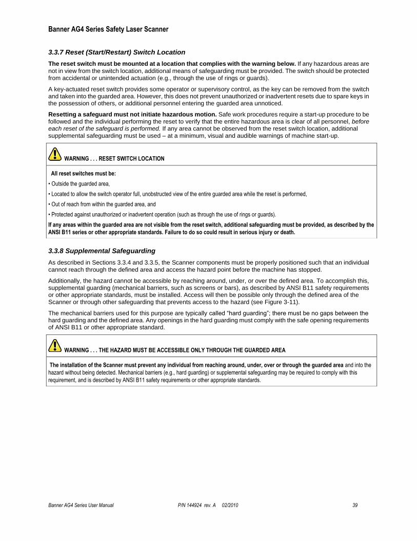
Banner AG4 Series Safety Laser Scanner
Banner AG4 Series User Manual P/N 144924 rev. A 02/2010 39
3.3.7 Reset (Start/Restart) Switch Location
The reset switch must be mounted at a location that complies with the warning below. If any hazardous areas are
not in view from the switch location, additional means of safeguarding must be provided. The switch should be protected from accidental or unintended actuation (e.g., through the use of rings or guards).
A key-actuated reset switch provides some operator or supervisory control, as the key can be removed from the switch and taken into the guarded area. However, this does not prevent unauthorized or inadvertent resets due to spare keys in the possession of others, or additional personnel entering the guarded area unnoticed.
Resetting a safeguard must not initiate hazardous motion. Safe work procedures require a start-up procedure to be followed and the individual performing the reset to verify that the entire hazardous area is clear of all personnel, before each reset of the safeguard is performed. If any area cannot be observed from the reset switch location, additional supplemental safeguarding must be used – at a minimum, visual and audible warnings of machine start-up.
3.3.8 Supplemental Safeguarding
As described in Sections 3.3.4 and 3.3.5, the Scanner components must be properly positioned such that an individual cannot reach through the defined area and access the hazard point before the machine has stopped.
Additionally, the hazard cannot be accessible by reaching around, under, or over the defined area. To accomplish this, supplemental guarding (mechanical barriers, such as screens or bars), as described by ANSI B11 safety requirements or other appropriate standards, must be installed. Access will then be possible only through the defined area of the Scanner or through other safeguarding that prevents access to the hazard (see Figure 3-11).
The mechanical barriers used for this purpose are typically called ―hard guarding‖; there must be no gaps between the hard guarding and the defined area. Any openings in the hard guarding must comply with the safe opening requirements of ANSI B11 or other appropriate standard.
WARNING . . . RESET SWITCH LOCATION
All reset switches must be:
• Outside the guarded area,
• Located to allow the switch operator full, unobstructed view of the entire guarded area while the reset is performed,
• Out of reach from within the guarded area, and
• Protected against unauthorized or inadvertent operation (such as through the use of rings or guards).
If any areas within the guarded area are not visible from the reset switch, additional safeguarding must be provided, as described by the
ANSI B11 series or other appropriate standards. Failure to do so could result in serious injury or death.
WARNING . . . THE HAZARD MUST BE ACCESSIBLE ONLY THROUGH THE GUARDED AREA
The installation of the Scanner must prevent any individual from reaching around, under, over or through the guarded area and into the
hazard without being detected. Mechanical barriers (e.g., hard guarding) or supplemental safeguarding may be required to comply with this
requirement, and is described by ANSI B11 safety requirements or other appropriate standards.
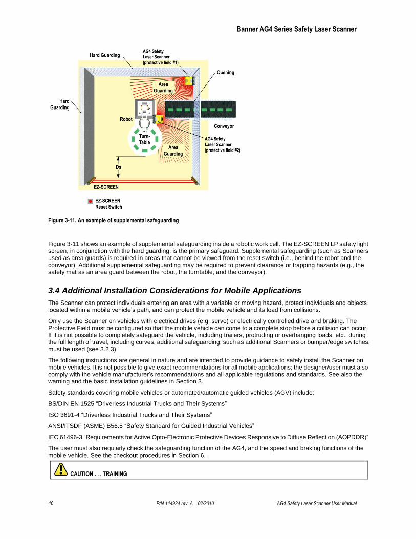
Banner AG4 Series Safety Laser Scanner
40 P/N 144924 rev. A 02/2010 AG4 Safety Laser Scanner User Manual
Figure 3-11. An example of supplemental safeguarding
Figure 3-11 shows an example of supplemental safeguarding inside a robotic work cell. The EZ-SCREEN LP safety light screen, in conjunction with the hard guarding, is the primary safeguard. Supplemental safeguarding (such as Scanners used as area guards) is required in areas that cannot be viewed from the reset switch (i.e., behind the robot and the conveyor). Additional supplemental safeguarding may be required to prevent clearance or trapping hazards (e.g., the safety mat as an area guard between the robot, the turntable, and the conveyor).
3.4 Additional Installation Considerations for Mobile Applications
The Scanner can protect individuals entering an area with a variable or moving hazard, protect individuals and objects located within a mobile vehicle’s path, and can protect the mobile vehicle and its load from collisions.
Only use the Scanner on vehicles with electrical drives (e.g. servo) or electrically controlled drive and braking. The Protective Field must be configured so that the mobile vehicle can come to a complete stop before a collision can occur. If it is not possible to completely safeguard the vehicle, including trailers, protruding or overhanging loads, etc., during the full length of travel, including curves, additional safeguarding, such as additional Scanners or bumper/edge switches, must be used (see 3.2.3).
The following instructions are general in nature and are intended to provide guidance to safely install the Scanner on mobile vehicles. It is not possible to give exact recommendations for all mobile applications; the designer/user must also comply with the vehicle manufacturer’s recommendations and all applicable regulations and standards. See also the warning and the basic installation guidelines in Section 3.
Safety standards covering mobile vehicles or automated/automatic guided vehicles (AGV) include:
BS/DIN EN 1525 ―Driverless Industrial Trucks and Their Systems‖
ISO 3691-4 ―Driverless Industrial Trucks and Their Systems‖
ANSI/ITSDF (ASME) B56.5 ―Safety Standard for Guided Industrial Vehicles‖
IEC 61496-3 ―Requirements for Active Opto-Electronic Protective Devices Responsive to Diffuse Reflection (AOPDDR)‖
The user must also regularly check the safeguarding function of the AG4, and the speed and braking functions of the mobile vehicle. See the checkout procedures in Section 6.
CAUTION . . . TRAINING

Banner AG4 Series Safety Laser Scanner
Banner AG4 Series User Manual P/N 144924 rev. A 02/2010 41
The user must instruct all individuals that may interact with the mobile vehicle (at a minimum):
not to approach the vehicle directly or from the sides while moving
familiarize with warning signals or lights/beacon
familiarize with the size of the Warning and Protective Fields
3.4.1 Mounting
The mounting of the Scanner should take into account:
the surface contour of the path of the vehicle including holes, bumps, inclines, ramps, and other variations in the surface,
deflection of springs or other vibration dampeners that could cause the plain of the Protective Field to vary,
unmonitored areas created by the installation of the AG4 (see below and Section 3.3.1).
The point of mounting is typically in the center of the leading edge of the vehicle and is aligned horizontally to achieve a consistent scanning height over the entire Protective Field.
Mounting Height
The Scanner should be mounted as low as possible in order to prevent people from passing beneath the sensing field by lying on the floor. BS/DIN EN 1525 and IEC 61496-3 recommend that the Protective Field with a resolution of 70 mm be as near as possible to the floor, but no greater than 200 mm (7.9") above the floor (see Figure 3.12). In general, a height of 150 mm (5.9‖) has been recognized by industry to be the most advantageous height above the floor.
Figure 3-12. Determining mounting height
Unmonitored Areas
Mounting the Scanner on the mobile vehicle must not create unmonitored areas between the Protective Field and the vehicle, such that the Scanner cannot respond to an object with a cross-section of 70 mm or more (see below and Section 3.3.1).
Unmonitored areas on a mobile vehicle can be prevented by:
Design/contour of the mobile vehicle
Position of the Scanner
Mounting the Scanner recessed within the vehicle
Mounting the Scanner under a physical guard or overhanging parts of frame
Using supplemental safeguarding, such as bumper or edge switches
Using mechanical barriers to prevent access
3.4.2 Configuration Considerations
For mobile vehicle applications, the application option ―AGV – Automated Guided Vehicle‖ is typically chosen; however the risk assessment should determine the appropriate option (see Section 3.1).
Table 6. AGV Application
Application Configuration Description
AGV – Automated guided vehicle
Horizontal Protective Field - mobile Resolution = 70 mm,
Banner AG4 Series Safety Laser Scanner
42 P/N 144924 rev. A 02/2010 AG4 Safety Laser Scanner User Manual
Maximum Protective Field range: AG4-4E = 4 m (13.2'); AG4-6E = 6.25 m (20.6') Start/Restart Interlock selectable (Manual or Auto reset) Default = Automatic Start and Restart enabled (Auto)
Start/Restart (Reset) Interlock
The default configuration is automatic start and restart (automatic reset) with a 2 second delay after the Protective Field becomes clear. The 2 second OSSD ON-delay is required by BS/DIN EN1525 and is meant to allow an individual to fully clear the area protected by the Scanner.
In the AGV application option, the user has the choice of ―Automatic start,‖ ―Start Interlock‖ (manual reset at power-up), or ―Start test.‖ This option affects all Field Pairs and is not dependent on Field Pair switchover parameters. (See Section 1.12.1 and 1.12.4 for complete information.)
Scanner Response Time
The ―AGV – Automated Guided Vehicle‖ application option automatically sets the Scanner response time to the 160 ms default. The user may enter values from 80 ms to 640 ms, in 40 ms increments.
Vehicle Speed
The vehicle's expected maximum speed should be identified in the configuration. This allows the AG4 algorithm to maximize the interference (dust) immunity. The options are up to 1500 mm/s, up to 2500 mm/s, up to 4000 mm/s, and over 4000 mm/s (default).
Field Pair Switchover
In applications that incorporate Field Pair switchover, Minimum Distance D and Side Distance Z must be calculated
individually for all Protective Field pairs.
3.4.3 Protective Field Area – Length and Width
The horizontal Protective Field will prevent a collision only if the edge of the field in the direction of movement is sufficiently distant from the vehicle and its load. This dimension (length) of the Protective Field is described as the Minimum Distance D. The Side Distance Z (or the width of the Protective Field) is used to ensure that the sides of the
vehicle or a protruding load do not create a hazard.
It is highly recommended that an oversized Warning Field (in comparison to the Protective Field) be used. The
Warning Field and its associated output signal the approach of the mobile vehicle (e.g., by sounding a horn or illuminating lights/beacons), and reduce the speed of the mobile vehicle. This can reduce the need or the amount of braking and wear on the drive mechanisms.
The Protective Field configuration must take into account trapping/crushing hazards that could be created by physical objects near the path of the mobile vehicle. An example would be an elevated conveyor that the sensing field of the Side Distance Z passes under, but does not provide enough clearance. This situation can occur if the distance between the
end of the conveyor and the side of the mobile vehicle is less than 500 mm (20") per ISO 13854 (EN349) ―Minimum Gaps to Avoid Crushing.‖
The following items apply to the calculation for determining the Minimum Distance D (Protective Field length):
Maximum speed of the AGV (Do not rely on the speed reduction initiated by the Warning Field!)
The Scanner response time
The response time of the mobile vehicle drive logic, including the response time of any interfacing devices, such as UM-FA-..A safety module (25 ms)
The braking distance of the AGV (including environmental conditions, such as wet or slippery flooring)
Absence or lack of clearance in front or to the sides of the AGV
The speed of movement of an individual
The reduced efficiency of the braking system, due to wear
WARNING . . . AG4 RESPONSE TIME ADJUSTMENTS
Do not increase the Scanner’s 80 ms response time for vertically positioned Protective Fields such as work cell access (Entry/ Exit) or perimeter guarding applications where a person could move quickly through the Protective Field without being detected.
Failure to follow this recommendation could result in serious bodily injury or death.
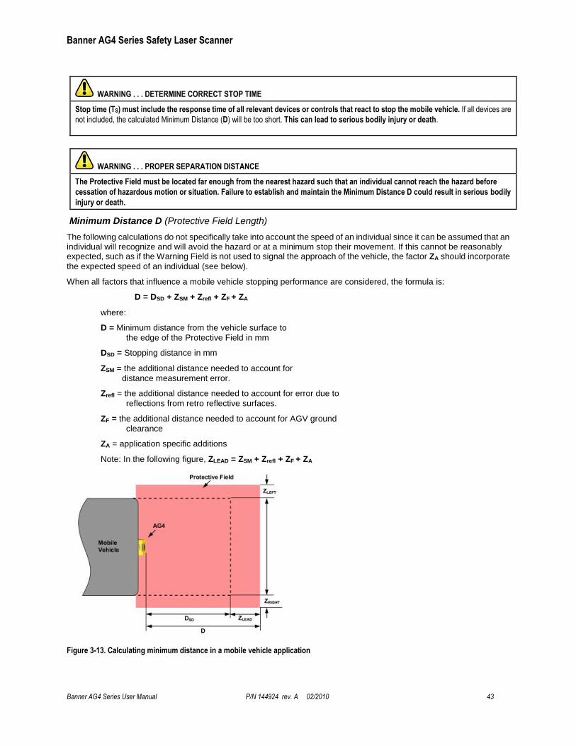
Banner AG4 Series Safety Laser Scanner
Banner AG4 Series User Manual P/N 144924 rev. A 02/2010 43
WARNING . . . DETERMINE CORRECT STOP TIME
Stop time (TS) must include the response time of all relevant devices or controls that react to stop the mobile vehicle. If all devices are
not included, the calculated Minimum Distance (D) will be too short. This can lead to serious bodily injury or death.
WARNING . . . PROPER SEPARATION DISTANCE
The Protective Field must be located far enough from the nearest hazard such that an individual cannot reach the hazard before
cessation of hazardous motion or situation. Failure to establish and maintain the Minimum Distance D could result in serious bodily
injury or death.
Minimum Distance D (Protective Field Length)
The following calculations do not specifically take into account the speed of an individual since it can be assumed that an individual will recognize and will avoid the hazard or at a minimum stop their movement. If this cannot be reasonably expected, such as if the Warning Field is not used to signal the approach of the vehicle, the factor ZA should incorporate
the expected speed of an individual (see below).
When all factors that influence a mobile vehicle stopping performance are considered, the formula is:
D = DSD + ZSM + Zrefl + ZF + ZA
where:
D = Minimum distance from the vehicle surface to
the edge of the Protective Field in mm
DSD = Stopping distance in mm
ZSM = the additional distance needed to account for
distance measurement error.
Zrefl = the additional distance needed to account for error due to
reflections from retro reflective surfaces.
ZF = the additional distance needed to account for AGV ground
clearance
ZA = application specific additions
Note: In the following figure, ZLEAD = ZSM + Zrefl + ZF + ZA
Figure 3-13. Calculating minimum distance in a mobile vehicle application
Banner AG4 Series Safety Laser Scanner
44 P/N 144924 rev. A 02/2010 AG4 Safety Laser Scanner User Manual
DSD = [VMAX x (TS + TR)] + DB
where:
DSD = Stopping distance in mm
VMAX = the maximum velocity as stated by the manufacturer of the mobile vehicle
TS = maximum stop time (in seconds) of the mobile vehicle (see note 1 below)
TR = maximum response time (in seconds) of the Scanner (see note 2 below)
DB = Braking Distance at full load and speed as stated by the manufacturer of the mobile
vehicle and other environmental factors (see note 3 below)
Notes
1. TS for the mobile vehicle should be supplied by its manufacturer. TS must include the response time of all devices or controls that react to stop the vehicle (e.g., UM-FA-9A Safety Module), which are added to determine the total time to cause braking/stopping. If all devices are not included, the calculated distance (DSD) will be too short and serious injury could result.
2. Consideration for Adjacent Scanners. When adjacent Scanners share the same detection plane and have an unobstructed view of each other, an additional 40 ms time must be added to the response times of both Scanners. If the adjacent detection planes are shielded so that there is no clear line of sight between Scanners or the detection planes are offset by at least 100 mm (4"), then the 40 ms addition is not required.
3. Braking Distance (DB) should incorporate factors such as brake deterioration and environmental factors that can impact braking (such as loose dirt/gravel, wet/moisture, icing, etc.) which can add 10% or more to the manufacturer’s stated distance. It should be noted that braking distance is not a linear function; it increases by a square function as velocity increases.
Additional Distance Factors (Z) Specific for Mobile Applications
For mobile applications, two additional factors must be considered: ZSM and Zrefl.
ZSM Measurement Tolerance Factor
ZSM is the additional distance needed to account for distance measurement error. The value for ZSM is a
function of the distance from the Scanner (rotary mirror’s center point) to the furthest point of the Protective Field, measured along the radial (RG).
For Horizontal Protective Fields (parallel approach):
ZSM = 83 mm (3.3") for Protective Fields RG < 3500 mm (138 ")
ZSM = 100 mm (4") for Protective Fields RG ≥ 3500 mm (138")
Zrefl Retro Reflector Factor
Zrefl is the additional distance needed to account for error due to reflections from retro-reflective or shiny surfaces
that are present in the scanning plane.
No retro-reflectors: Zrefl = 0
Retro-reflectors located within the scanning plane of the Protective Field: Zrefl = 100 mm (4")
ZF Mobile Vehicle (AGV) Ground Clearance
The additional distance ZF is required if the mobile vehicle does not have sufficient ground clearance (HF) such
that there is no space under the vehicle or Scanner for the tips of feet. If the wheels are mounted near the side wall, always add an additional distance ZF ≥ 150 mm; otherwise ZF is determined according to Figure 3-14.
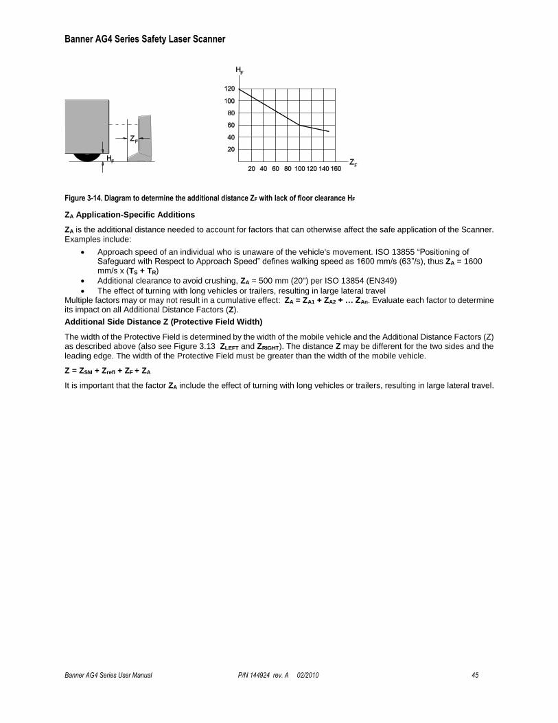
Banner AG4 Series Safety Laser Scanner
Banner AG4 Series User Manual P/N 144924 rev. A 02/2010 45
Figure 3-14. Diagram to determine the additional distance ZF with lack of floor clearance HF
ZA Application-Specific Additions
ZA is the additional distance needed to account for factors that can otherwise affect the safe application of the Scanner.
Examples include:
Approach speed of an individual who is unaware of the vehicle's movement. ISO 13855 ―Positioning of Safeguard with Respect to Approach Speed‖ defines walking speed as 1600 mm/s (63‖/s), thus ZA = 1600 mm/s x (TS + TR)
Additional clearance to avoid crushing, ZA = 500 mm (20") per ISO 13854 (EN349)
The effect of turning with long vehicles or trailers, resulting in large lateral travel Multiple factors may or may not result in a cumulative effect: ZA = ZA1 + ZA2 + … ZAn. Evaluate each factor to determine its impact on all Additional Distance Factors (Z).
Additional Side Distance Z (Protective Field Width)
The width of the Protective Field is determined by the width of the mobile vehicle and the Additional Distance Factors (Z) as described above (also see Figure 3.13 ZLEFT and ZRIGHT). The distance Z may be different for the two sides and the
leading edge. The width of the Protective Field must be greater than the width of the mobile vehicle.
Z = ZSM + Zrefl + ZF + ZA
It is important that the factor ZA include the effect of turning with long vehicles or trailers, resulting in large lateral travel.
Banner AG4 Series Safety Laser Scanner
46 P/N 144924 rev. A 02/2010 AG4 Safety Laser Scanner User Manual
3.4.4 Mobile Side Guarding on AGVs (Vertical Protective Fields)
If the Additional Side Distance Z cannot be complied with or if additional safeguarding is otherwise required, additional
AG4 vertical Protective Fields can be used (see Application Guide p/n 147900).
The Protective Field must be configured so that the mobile vehicle can come to a complete stop before a collision can occur. In the case of vertical Protective Fields on mobile vehicles, the Scanner is typically mounted facing down at a slight tilt (such that the lower edge of the Protective Field extends a distance of Z as described above, if possible). To determine the dimension to the edge of the side of the Protective Field use the Minimum Distance (D) formula described above.
The Scanner should be configured with a resolution of at least 150 mm to detect the torso of an individual (i.e. ―Body protection –danger zone guarding‖). The risk assessment should determine if a smaller resolution is necessary.
Table 7. Vertical Guarding Application
Application Configuration Description
Vertical Guarding – Body Detection (Body protection –danger zone guarding)
Vertical Protective Field - stationary Resolution = 150 mm, Maximum Protective Field range: AG4-4E = 4 m (13.2'); AG4-6E = 6.25 m (20.6') Start/Restart Interlock selectable (Manual or Auto reset) Default = Start/Restart Interlock enabled (Manual) Note: Reference contour (surface) monitoring function is manually configured.
If it is not possible to completely safeguard the vehicle (including trailers, protruding or overhanging loads, etc.), during the full length of travel (including curves), then additional safeguarding (e.g., additional Scanners or bumper/edge switches) must be used.
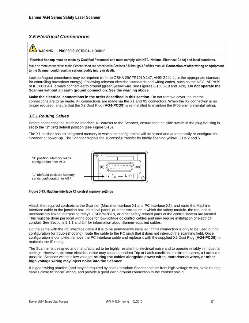
Banner AG4 Series Safety Laser Scanner
Banner AG4 Series User Manual P/N 144924 rev. A 02/2010 47
3.5 Electrical Connections
Lockout/tagout procedures may be required (refer to OSHA 29CFR1910.147, ANSI Z244-1, or the appropriate standard for controlling hazardous energy). Following relevant electrical standards and wiring codes, such as the NEC, NFPA79 or IEC60204-1, always connect earth ground (green/yellow wire, see Figures 3-18, 3-19 and 3-20). Do not operate the Scanner without an earth ground connection. See the warning above.
Make the electrical connections in the order described in this section. Do not remove cover; no internal
connections are to be made. All connections are made via the X1 and X2 connectors. When the X2 connection is no longer required, ensure that the X2 Dust Plug (AG4-PCD9) is re-installed to maintain the IP65 environmental rating.
3.5.1 Routing Cables
Before connecting the Machine Interface X1 cordset to the Scanner, ensure that the slide switch in the plug housing is set to the "1" (left) default position (see Figure 3-15).
The X1 cordset has an integrated memory in which the configuration will be stored and automatically re-configure the Scanner at power-up. The Scanner signals the successful transfer by briefly flashing yellow LEDs 2 and 5.
Figure 3-15. Machine Interface X1 cordset memory settings
Attach the required cordsets to the Scanner (Machine Interface X1 and PC Interface X2), and route the Machine Interface cable to the junction box, electrical panel, or other enclosure in which the safety module, the redundant mechanically linked interposing relays, FSDs/MPCEs, or other safety-related parts of the control system are located. This must be done per local wiring code for low-voltage dc control cables and may require installation of electrical conduit. See Sections 2.1.1 and 2.4 for information about Banner-supplied cables.
Do the same with the PC interface cable if it is to be permanently installed; if this connection is only to be used during configuration (or troubleshooting), route the cable to the PC such that it does not interrupt the scanning field. Once configuration is complete, remove the PC Interface cable and replace it with the supplied X2 Dust Plug (AG4-PCD9) to
maintain the IP rating.
The Scanner is designed and manufactured to be highly resistant to electrical noise and to operate reliably in industrial settings. However, extreme electrical noise may cause a random Trip or Latch condition; in extreme cases, a Lockout is possible. Scanner wiring is low voltage; routing the cables alongside power wires, motor/servo wires, or other high voltage wiring may inject noise into the Scanner.
It is good wiring practice (and may be required by code) to isolate Scanner cables from high-voltage wires, avoid routing cables close to ―noisy‖ wiring, and provide a good earth ground connection to the cordset shield.
WARNING . . . PROPER ELECTRICAL HOOKUP
Electrical hookup must be made by Qualified Personnel and must comply with NEC (National Electrical Code) and local standards.
Make no more connections to the Scanner than are described in Sections 3.5 through 3.8 of this manual. Connection of other wiring or equipment
to the Scanner could result in serious bodily injury or death.
―X‖ position: Memory reads configuration from AG4
"1" (default) position: Memory sends configuration to AG4
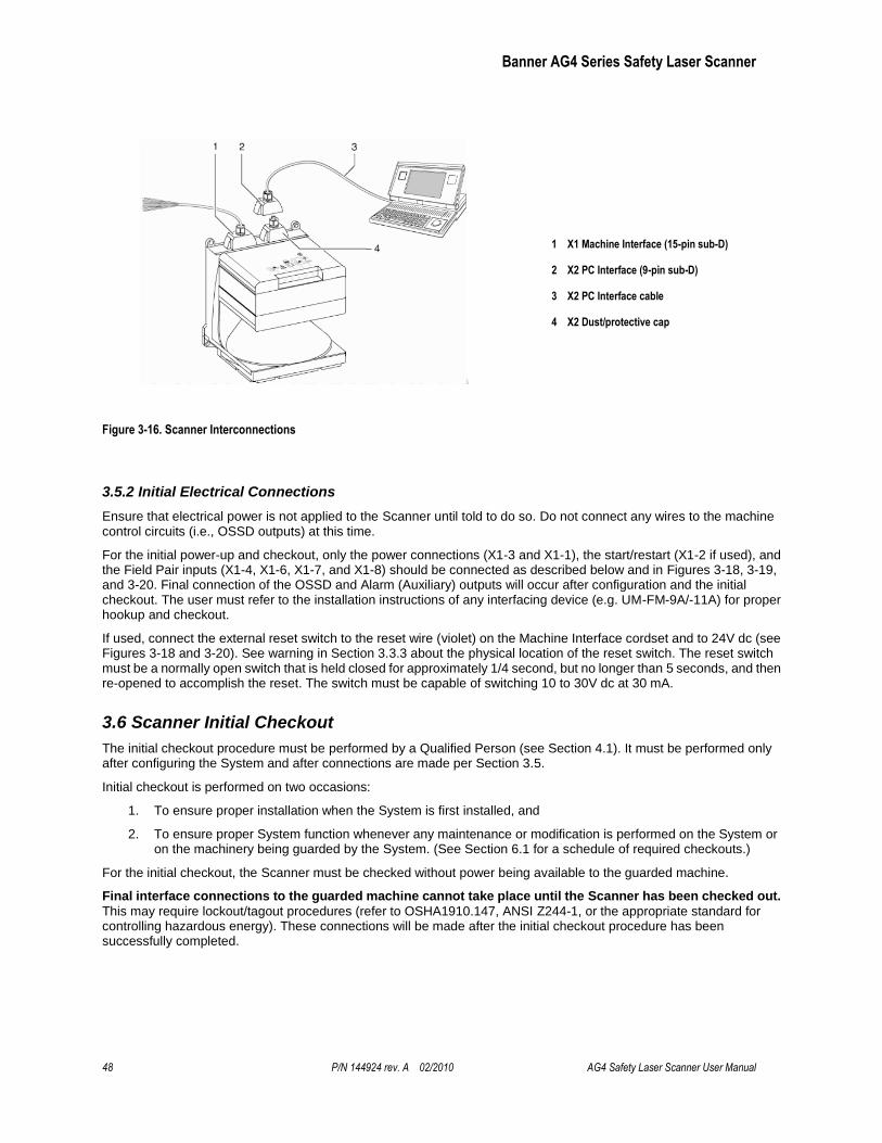
Banner AG4 Series Safety Laser Scanner
48 P/N 144924 rev. A 02/2010 AG4 Safety Laser Scanner User Manual
1 X1 Machine Interface (15-pin sub-D)
2 X2 PC Interface (9-pin sub-D)
3 X2 PC Interface cable
4 X2 Dust/protective cap
Figure 3-16. Scanner Interconnections
3.5.2 Initial Electrical Connections
Ensure that electrical power is not applied to the Scanner until told to do so. Do not connect any wires to the machine control circuits (i.e., OSSD outputs) at this time.
For the initial power-up and checkout, only the power connections (X1-3 and X1-1), the start/restart (X1-2 if used), and the Field Pair inputs (X1-4, X1-6, X1-7, and X1-8) should be connected as described below and in Figures 3-18, 3-19, and 3-20. Final connection of the OSSD and Alarm (Auxiliary) outputs will occur after configuration and the initial checkout. The user must refer to the installation instructions of any interfacing device (e.g. UM-FM-9A/-11A) for proper hookup and checkout.
If used, connect the external reset switch to the reset wire (violet) on the Machine Interface cordset and to 24V dc (see Figures 3-18 and 3-20). See warning in Section 3.3.3 about the physical location of the reset switch. The reset switch must be a normally open switch that is held closed for approximately 1/4 second, but no longer than 5 seconds, and then re-opened to accomplish the reset. The switch must be capable of switching 10 to 30V dc at 30 mA.
3.6 Scanner Initial Checkout
The initial checkout procedure must be performed by a Qualified Person (see Section 4.1). It must be performed only after configuring the System and after connections are made per Section 3.5.
Initial checkout is performed on two occasions:
1. To ensure proper installation when the System is first installed, and
2. To ensure proper System function whenever any maintenance or modification is performed on the System or on the machinery being guarded by the System. (See Section 6.1 for a schedule of required checkouts.)
For the initial checkout, the Scanner must be checked without power being available to the guarded machine.
Final interface connections to the guarded machine cannot take place until the Scanner has been checked out.
This may require lockout/tagout procedures (refer to OSHA1910.147, ANSI Z244-1, or the appropriate standard for controlling hazardous energy). These connections will be made after the initial checkout procedure has been successfully completed.
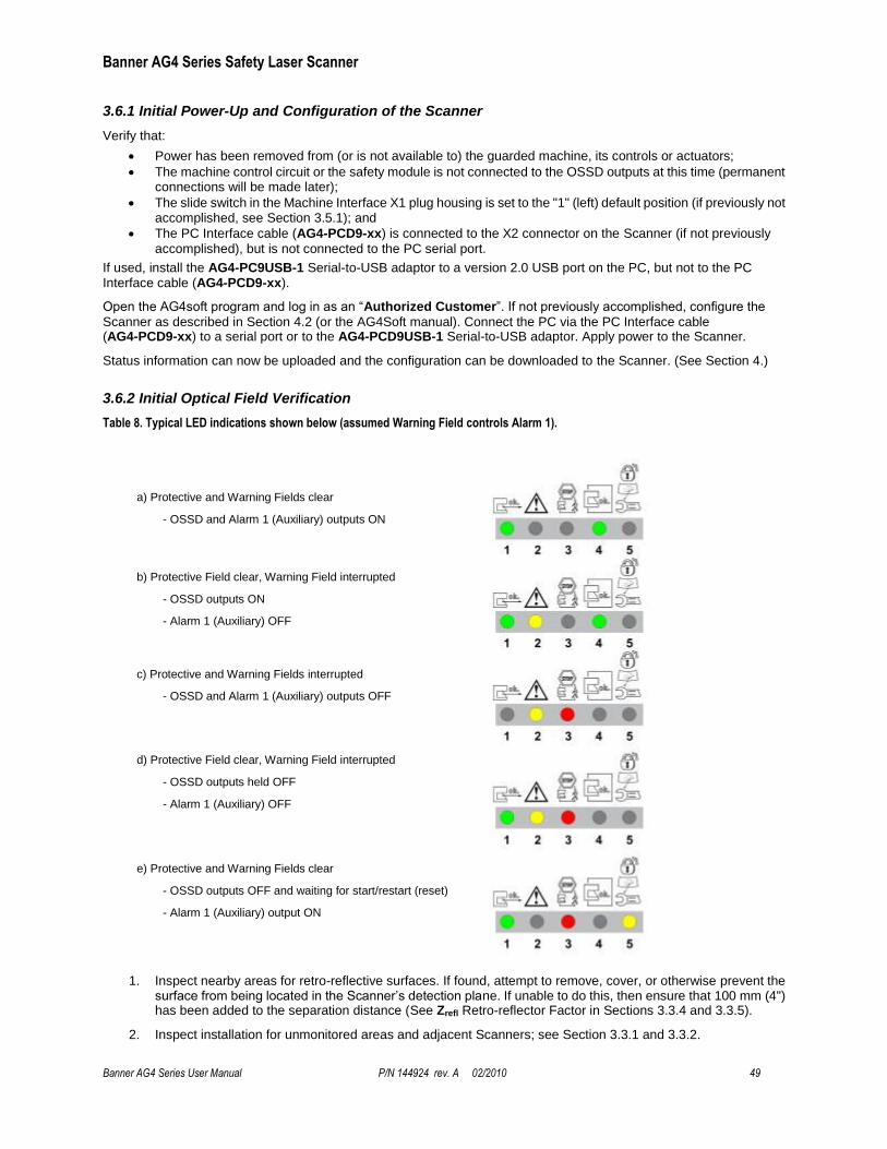
Banner AG4 Series Safety Laser Scanner
Banner AG4 Series User Manual P/N 144924 rev. A 02/2010 49
3.6.1 Initial Power-Up and Configuration of the Scanner
Verify that:
Power has been removed from (or is not available to) the guarded machine, its controls or actuators;
The machine control circuit or the safety module is not connected to the OSSD outputs at this time (permanent connections will be made later);
The slide switch in the Machine Interface X1 plug housing is set to the "1" (left) default position (if previously not accomplished, see Section 3.5.1); and
The PC Interface cable (AG4-PCD9-xx) is connected to the X2 connector on the Scanner (if not previously
accomplished), but is not connected to the PC serial port.
If used, install the AG4-PC9USB-1 Serial-to-USB adaptor to a version 2.0 USB port on the PC, but not to the PC Interface cable (AG4-PCD9-xx).
Open the AG4soft program and log in as an ―Authorized Customer‖. If not previously accomplished, configure the
Scanner as described in Section 4.2 (or the AG4Soft manual). Connect the PC via the PC Interface cable (AG4-PCD9-xx) to a serial port or to the AG4-PCD9USB-1 Serial-to-USB adaptor. Apply power to the Scanner.
Status information can now be uploaded and the configuration can be downloaded to the Scanner. (See Section 4.)
3.6.2 Initial Optical Field Verification
Table 8. Typical LED indications shown below (assumed Warning Field controls Alarm 1).
a) Protective and Warning Fields clear
- OSSD and Alarm 1 (Auxiliary) outputs ON
b) Protective Field clear, Warning Field interrupted
- OSSD outputs ON
- Alarm 1 (Auxiliary) OFF
c) Protective and Warning Fields interrupted
- OSSD and Alarm 1 (Auxiliary) outputs OFF
d) Protective Field clear, Warning Field interrupted
- OSSD outputs held OFF
- Alarm 1 (Auxiliary) OFF
e) Protective and Warning Fields clear
- OSSD outputs OFF and waiting for start/restart (reset)
- Alarm 1 (Auxiliary) output ON
1. Inspect nearby areas for retro-reflective surfaces. If found, attempt to remove, cover, or otherwise prevent the surface from being located in the Scanner’s detection plane. If unable to do this, then ensure that 100 mm (4") has been added to the separation distance (See Zrefl Retro-reflector Factor in Sections 3.3.4 and 3.3.5).
2. Inspect installation for unmonitored areas and adjacent Scanners; see Section 3.3.1 and 3.3.2.
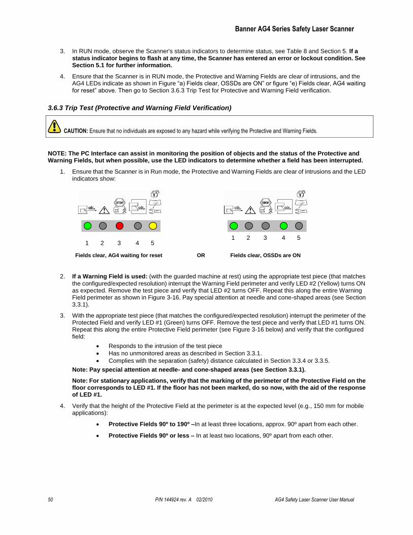
Banner AG4 Series Safety Laser Scanner
50 P/N 144924 rev. A 02/2010 AG4 Safety Laser Scanner User Manual
3. In RUN mode, observe the Scanner's status indicators to determine status, see Table 8 and Section 5. If a status indicator begins to flash at any time, the Scanner has entered an error or lockout condition. See Section 5.1 for further information.
4. Ensure that the Scanner is in RUN mode, the Protective and Warning Fields are clear of intrusions, and the AG4 LEDs indicate as shown in Figure ―a) Fields clear, OSSDs are ON‖ or figure ―e) Fields clear, AG4 waiting for reset‖ above. Then go to Section 3.6.3 Trip Test for Protective and Warning Field verification.
3.6.3 Trip Test (Protective and Warning Field Verification)
NOTE: The PC Interface can assist in monitoring the position of objects and the status of the Protective and Warning Fields, but when possible, use the LED indicators to determine whether a field has been interrupted.
1. Ensure that the Scanner is in Run mode, the Protective and Warning Fields are clear of intrusions and the LED indicators show:
Fields clear, AG4 waiting for reset OR Fields clear, OSSDs are ON
2. If a Warning Field is used: (with the guarded machine at rest) using the appropriate test piece (that matches
the configured/expected resolution) interrupt the Warning Field perimeter and verify LED #2 (Yellow) turns ON as expected. Remove the test piece and verify that LED #2 turns OFF. Repeat this along the entire Warning Field perimeter as shown in Figure 3-16. Pay special attention at needle and cone-shaped areas (see Section 3.3.1).
3. With the appropriate test piece (that matches the configured/expected resolution) interrupt the perimeter of the Protected Field and verify LED #1 (Green) turns OFF. Remove the test piece and verify that LED #1 turns ON. Repeat this along the entire Protective Field perimeter (see Figure 3-16 below) and verify that the configured field:
Responds to the intrusion of the test piece
Has no unmonitored areas as described in Section 3.3.1.
Complies with the separation (safety) distance calculated in Section 3.3.4 or 3.3.5.
Note: Pay special attention at needle- and cone-shaped areas (see Section 3.3.1).
Note: For stationary applications, verify that the marking of the perimeter of the Protective Field on the floor corresponds to LED #1. If the floor has not been marked, do so now, with the aid of the response of LED #1.
4. Verify that the height of the Protective Field at the perimeter is at the expected level (e.g., 150 mm for mobile applications):
Protective Fields 90º to 190º –In at least three locations, approx. 90º apart from each other.
Protective Fields 90º or less – In at least two locations, 90º apart from each other.
CAUTION: Ensure that no individuals are exposed to any hazard while verifying the Protective and Warning Fields.
1 2 3 4 5 1 2 3 4 5
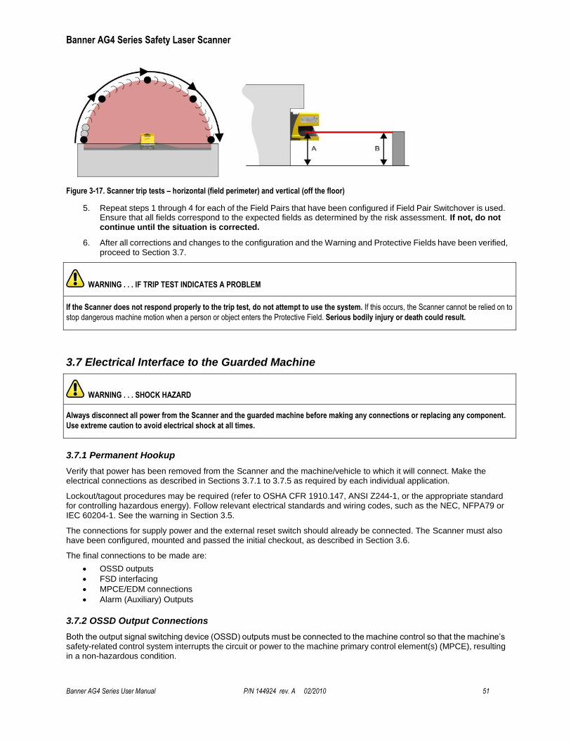
Banner AG4 Series Safety Laser Scanner
Banner AG4 Series User Manual P/N 144924 rev. A 02/2010 51
Figure 3-17. Scanner trip tests – horizontal (field perimeter) and vertical (off the floor)
5. Repeat steps 1 through 4 for each of the Field Pairs that have been configured if Field Pair Switchover is used. Ensure that all fields correspond to the expected fields as determined by the risk assessment. If not, do not continue until the situation is corrected.
6. After all corrections and changes to the configuration and the Warning and Protective Fields have been verified, proceed to Section 3.7.
3.7 Electrical Interface to the Guarded Machine
3.7.1 Permanent Hookup
Verify that power has been removed from the Scanner and the machine/vehicle to which it will connect. Make the electrical connections as described in Sections 3.7.1 to 3.7.5 as required by each individual application.
Lockout/tagout procedures may be required (refer to OSHA CFR 1910.147, ANSI Z244-1, or the appropriate standard for controlling hazardous energy). Follow relevant electrical standards and wiring codes, such as the NEC, NFPA79 or IEC 60204-1. See the warning in Section 3.5.
The connections for supply power and the external reset switch should already be connected. The Scanner must also have been configured, mounted and passed the initial checkout, as described in Section 3.6.
The final connections to be made are:
OSSD outputs
FSD interfacing
MPCE/EDM connections
Alarm (Auxiliary) Outputs
3.7.2 OSSD Output Connections
Both the output signal switching device (OSSD) outputs must be connected to the machine control so that the machine’s safety-related control system interrupts the circuit or power to the machine primary control element(s) (MPCE), resulting in a non-hazardous condition.
WARNING . . . IF TRIP TEST INDICATES A PROBLEM
If the Scanner does not respond properly to the trip test, do not attempt to use the system. If this occurs, the Scanner cannot be relied on to
stop dangerous machine motion when a person or object enters the Protective Field. Serious bodily injury or death could result.
WARNING . . . SHOCK HAZARD
Always disconnect all power from the Scanner and the guarded machine before making any connections or replacing any component.
Use extreme caution to avoid electrical shock at all times.
Banner AG4 Series Safety Laser Scanner
52 P/N 144924 rev. A 02/2010 AG4 Safety Laser Scanner User Manual
Final switching devices (FSDs) typically accomplish this when the OSSDs go to an OFF state. See Figure 3-19. Refer to the output specifications in Section 2.2 and the warnings below before making OSSD output connections and interfacing the Scanner to the machine.
3.7.2 FSD Interfacing Connections
Final switching devices (FSDs) can take many forms, although the most common are forced-guided, mechanically linked relays or an interface module. The mechanical linkage between the contacts allows the device to be monitored by the external device monitoring circuit for certain failures.
Depending on the application, the use of FSDs can facilitate controlling voltage and current that differs from the OSSD outputs of the Scanner. FSDs can also be used to control an additional number of hazards, by creating multiple safety stop circuits.
Safety Stop (Protective Stop) Circuits
A safety stop allows for an orderly cessation of motion for safeguarding purposes, which results in the stopping of motion and removal of power from the MPCEs (assuming this does not create additional hazards). A safety stop circuit typically comprises a minimum of two normally open (N.O.) contacts from forced-guided, mechanically linked relays, which are monitored (via external device monitoring) to detect certain failures in order to prevent the loss of the safety function. Such a circuit can be described as a ―safe switching point.‖
Typically, safety stop circuits are either single-channel, which is a series connection of at least two N.O. contacts; or dual-channel, which is a separate connection of two N.O. contacts. In either method, the safety function relies on the use of redundant contacts to control a single hazard (if one contact fails ON, the second contact will arrest the hazard and prevent the next cycle from occurring). See Figure 3-19.
The interfacing of the safety stop circuits must be accomplished so that the safety function cannot be suspended, overridden, or defeated, unless accomplished in a manner at the same or greater degree of safety as the machine’s safety-related control system that includes the Scanner.
The normally open safety outputs from a safety module provide a series connection of redundant contacts that form safety stop circuits for use in either single-channel or dual-channel control. (See Figure 3-20.)
Dual-Channel Control
Dual-channel control provides the ability to electrically extend the safe switching point beyond the FSD contacts. With proper monitoring (i.e., EDM), this method of interfacing is capable of detecting certain failures in the control wiring between the safety stop circuit and the MPCEs. These failures include a short circuit of one channel to a secondary source of energy or voltage, or the loss of the switching ability of one of the FSD outputs. Such failures could lead to the loss of redundancy — or to a complete loss of safety, if not detected and corrected.
The possibility of a failure to the wiring increases as the physical distance between the FSD safety stop circuits and the MPCEs increases, as the length or the routing of the interconnecting wires increases, or if the FSD safety stop circuits
WARNING . . . INTERFACING OF BOTH OSSDS
Both of the OSSD (Output Signal Switching Device) outputs must be connected to the machine control so that the machine’s
safety-related control system interrupts the circuit to the machine primary control element(s), resulting in a non-hazardous condition.
Never wire an intermediate device(s) (e.g., PLC, PES, or PC) that can fail in such a manner that there is the loss of the safety stop
command, OR in such a manner that the safety function can be suspended, overridden, or defeated, unless accomplished with the same
or greater degree of safety.
WARNING . . . OSSD INTERFACING
To ensure proper operation, the Scanner OSSD output parameters and machine input parameters must be considered when interfacing
the Scanner solid-state OSSD outputs to machine inputs.
Machine control circuitry must be designed so that the maximum load resistance value is not exceeded and that the maximum specified OSSD
OFF-state voltage does not result in an ON condition. Failure to properly interface the OSSD outputs to the guarded machine could result in
serious bodily injury or death.
Banner AG4 Series Safety Laser Scanner
Banner AG4 Series User Manual P/N 144924 rev. A 02/2010 53
and the MPCEs are located in different enclosures. For this reason, dual-channel control with EDM monitoring should be used in any installation where the FSDs are located remotely from the MPCEs.
Single-Channel Control
Single-channel control uses a series connection of FSD contacts to form a safe switching point. After this point in the machine’s safety-related control system, failures can occur that would result in the loss of the safety function (such as a short-circuit to a secondary source of energy or voltage).
For this reason, single-channel control interfacing should be used only in installations where FSD safety stop circuits and the MPCEs are mounted within the same control panel, adjacent to each other, and are directly connected to each other; or where the possibility of such a failure can be excluded. If this cannot be achieved, then dual-channel control should be used.
Methods to exclude the possibility of these failures include, but are not limited to:
Physically separating interconnecting control wires from each other and from secondary sources of power.
Routing interconnecting control wires in separate conduit, runs, or channels.
Locating all elements (modules, switches, and devices under control) within one control panel, adjacent to each other, and directly connected with short wires.
Properly installing multi-conductor cabling and multiple wires through strain relief fittings. (Over-tightening of a strain-relief can cause short-circuits at that point.)
Using positive-opening or direct-drive components, installed and mounted in a positive mode.
3.7.3 Machine Primary Control Elements and External Device Monitoring
A machine primary control element (MPCE) is an ―electrically powered element that directly controls the normal operation of a machine in such a way that it is the last element (in time) to function when machine operation is to be initiated or arrested‖ (per IEC61496-1). Examples include motor contactors, clutch/brakes, valves, and solenoids.
Depending on the level of risk of harm, it may be required to provide redundant MPCEs or other control devices that are capable of immediately stopping the dangerous machine motion, irrespective of the state of the other. These two machine control channels need not be identical (they could also be diverse redundant), but the stop time performance of the machine (Ts, used to calculate the safety distance, see Sections 3.3.4 and 3.3.5) must take into account the slower of the two channels. Refer to Figure 3-20 or consult the machine manufacturer for additional information.
To ensure that an accumulation of failures does not compromise the redundant control scheme (i.e., cause a failure to danger) a method to verify the normal functioning of MPCEs or other control devices is required. The Scanner provides this function only when configured for manual start/restart (reset) with MPCE monitoring contacts wired in series with the reset (start/restart) switch as shown in Figure 3-19 (see also 3.3.7 Reset Switch Location).
When the Scanner is configured for Automatic Start/Restart (Reset), to properly monitor the MPCEs an External Device Monitoring (EDM) function must be provided by an external means from the Scanner. One example using the UM-FA-9A/-11A safety Module is shown in Figure 3-20. The UM-FA-9A/-11A can be configured for
both manual or automatic reset and provide the required EDM function.
For external device monitoring to function properly, each device must include a normally closed (N.C.), forced-guided (mechanically linked) contact that can accurately reflect the status of the device. This ensures that the normally open contacts, used for controlling hazardous motion, have a positive relationship with the normally closed monitoring contacts and can detect a failure to danger (e.g., contacts that welded closed or stuck ON).
It is strongly recommended that a normally closed, forced-guided monitoring contact of each FSD and MPCE be connected to EDM inputs (see Figures 3-19 and 3-20). If this is done, proper operation will be verified. Monitoring FSD and MPCE contacts is one method of maintaining control reliability (OSHA/ANSI) and Category 3 and 4 (ISO13849-1).
If monitoring contacts are not available or do not meet the design requirement of being forced-guided (mechanically linked), it is recommended to:
Replace the devices so that they are capable of being monitored, or
Incorporate the EDM function into the circuit as close to the MPCE as possible (e.g., monitor the FSDs), and
Employ use of well-tried, tested, and robust components, and generally accepted safety principles, including fault exclusion, into the design and installation to either eliminate, or reduce to an acceptable (minimal) level of risk, the possibility of undetected faults or failures that can result in the loss of the safety function.

Banner AG4 Series Safety Laser Scanner
54 P/N 144924 rev. A 02/2010 AG4 Safety Laser Scanner User Manual
The principle of fault exclusion allows the designer to design out the possibility of various failures and justify it through the risk assessment process to meet the required level of safety performance, such as the requirements of Category 2, 3 or 4. See ISO 13849-1/-2 for further information.
Notice Regarding MPCEs
Each of the machine primary control elements (MPCE1 and MPCE2) must be capable of immediately stopping the dangerous machine motion, regardless of the state of the other. The two machine control channels need not be identical, but the machine's stop time performance (TS, used to calculate separation distance) must be based on the
slower of the two channels.
3.7.4 Alarm (Auxiliary) Output
The Scanner has two alarm (auxiliary) status outputs that provide a PNP current-sourcing output (100 mA max.) that switches OFF to indicate the following conditions:
Alarm #1 (X1-5): If the Warning Field has been interrupted (default), if the AG4 has locked out, or both
conditions (configurable via the software).
Alarm #2 (X1-15): If the AG4 has locked out.
3.8 Preparing for System Operation
After the initial trip test has been accomplished (Section 3.4), and the OSSD safety output connections have been made to the machine to be controlled, the Scanner is ready for testing in combination with the guarded machine.
The operation of the Scanner with the guarded machine must be verified before the combined Scanner and machine may be put into service. To do this, a Qualified Person must perform the Commissioning Checkout Procedure described in Section 6.2.
WARNING . . . EDM MONITORING
If system is configured for “No Monitoring,” it is the user’s responsibility to ensure that this does not create a hazardous situation.
Banner AG4 Series Safety Laser Scanner
Banner AG4 Series User Manual P/N 144924 rev. A 02/2010 55
Figure 3-18. Hookup with FSD inputs

Banner AG4 Series Safety Laser Scanner
56 P/N 144924 rev. A 02/2010 AG4 Safety Laser Scanner User Manual
Figure 3-19. Hookup using UM module
Banner AG4 Series Safety Laser Scanner
Banner AG4 Series User Manual P/N 144924 rev. A 02/2010 57
Figure 3-20. Hookup to the SC22-3 Safety Controller
Banner AG4 Series Safety Laser Scanner
58 P/N 144924 rev. A 02/2010 AG4 Safety Laser Scanner User Manual
4. System Operation and Configuration
4.1 Security Protocol
Certain procedures for installing, maintaining and operating the Scanner must be performed by either Designated Persons or Qualified Persons.
A Designated Person is identified and designated in writing, by the employer, as being appropriately trained to perform the specified checkout procedures on the Scanner. A machine operator so designated may be a Designated Person. The Designated Person is empowered to:
Perform manual resets and hold possession of the reset key
Perform the daily Scanner checkout procedure
A Qualified Person, by possession of a recognized degree or certificate of professional training, or by extensive
knowledge, training and experience, has successfully demonstrated the ability to solve problems relating to the installation of the Scanner and its integration with the guarded machine. In addition to everything for which the Designated Person is empowered, the Qualified Person is empowered to:
Install the Scanner
Perform all Scanner checkout procedures
Control the password to access the Scanner’s configuration program
Access and change the Scanner’s configuration settings
Reset the system following a lockout condition
Perform maintenance and repairs as described in Section 5
See the AG4Soft Software Manual for information on changing and resetting the passwords.
4.2 System Configuration Settings
The AG4Soft configuration software is used to establish the Scanner operating parameters (for complete information, see the AG4Soft Software Manual). AG4Soft is included on the CD that was included with the Scanner and is also available on-line at:
http://www.bannerengineering.com/en-US/support/software
The Scanner is configured at the factory with the maximum Protective Field and activated start/restart interlock (manual reset). The Scanner must be configured by the user, according to the application.
4.2.1 Using the Configuration Wizard
During configuration (either for the purposes of an initial ―walk-through‖ or the final configuration), the Scanner should either not be connected to the PC, or if connected, the Scanner's power must be removed before the AG4soft program is opened. After the AG4soft program is running, the Scanner can be connected and power applied (see Section 4.3). Changes can be saved for downloading to the Scanner at a later time (see
Section 4.4). The remainder of this section is designed to be a ―walk-through‖ demonstration of the wizard.
After installing the AG4Soft configuration software, open the program by double-clicking on the shortcut icon. After reading and understanding the warning, click OK.
After a few moments, a ―Change Authorization Level‖ dialog box will appear. Select ―Authorized Customer‖ and enter the default password ―bannera‖.
Banner AG4 Series Safety Laser Scanner
Banner AG4 Series User Manual P/N 144924 rev. A 02/2010 59
NOTE: A dialog box may appear that says that there is a problem in identifying a serial port. If so, see Section 4.3.1 Establishing Communications Between the PC and the Scanner.
A dialog box should appear and ask if you would like to edit the configuration with the wizard; if so, click OK. If not prompted, the wizard can also be accessed by clicking on the ―Configuration‖ operating mode tab and then selecting in the menu bar path ―Configuration > Wizard‖.
Since no configuration is loaded in the AG4Soft program, an error message will be displayed. Click YES to load a
configuration file.
A dialog box asks you to select the appropriate Safety Laser Scanner. Choose AG4-4E or AG4-6E and click EXIT.
For the purpose of this walk-through, select ―standard.rs‖ file (double-click) from the list of configuration files provided in the ―Select a file to open‖ box. After the file is successfully loaded, click OK.
The Configuration Wizard opens with a dialog box that allows naming of the Scanner and a note or description of the location of the Scanner that the configuration will eventually be loaded into. No entry is required for the purposes of the walk-through. Click on NEXT.
Note: Navigation can move forward or backward through the wizard using the NEXT or BACK buttons. Clicking on OK
will end the wizard and open the AG4Soft Configuration window with the changes that had been made. Clicking on CANCEL will end the wizard without retaining the changes. To re-enter the wizard, click on ―Configuration‖ operating mode tab and select in the menu bar path, ―Configuration > Wizard‖.
The next few dialog boxes affect safety-relevant parameters. The first allows the choice of application options and start/restart or reset behavior (dependent on the application, see Section 3 Basic Installation Guidelines).

Banner AG4 Series Safety Laser Scanner
60 P/N 144924 rev. A 02/2010 AG4 Safety Laser Scanner User Manual
Select ―Freely Selectable Presettings‖ (for the purposes of this walk-through). While the resolution is fixed at 70 mm,
this option allows the most flexibility in learning the wizard.
The restart behavior default option is ―Restart Interlock‖ (Manual Reset). If Automatic restart (auto reset) is chosen, the ―Start Behavior‖ drop down menu becomes available allowing the choice of ―Automatic start‖, ―Start Interlock‖, and ―Start test‖ (see Section 1.12.1). These options determine the operation of the Scanner at power up. Restart delay (i.e., ON-delay) can be set from 160 ms to 10160 ms (default is 2000 ms). Click NEXT when complete.
The next dialog box allows setting of the Protective Field and Warning Field response times (individually). Care must be taken, because all fields are affected by these settings. After clicking NEXT, the dialog box allows activating (default) or deactivating the dust suppression algorithm. It is recommended to keep the algorithm activated. Click NEXT.
The fifth page of the wizard determines which Field Pairs the Scanner is allowed to start up (power up) when multiple Field Pairs are used. The sixth page determines which Field Pairs can switch to other Field Pairs during Field Pair switchover (see Section 1.12.4). After clicking on the appropriate boxes (use defaults for the walk-through), click NEXT
to complete.
Banner AG4 Series Safety Laser Scanner
Banner AG4 Series User Manual P/N 144924 rev. A 02/2010 61
The final dialog boxes in the wizard are considered ―Administrative Parameters‖ and allow configuration of the functionality of Alarm Output 1 (see Section 1.12.6), the amount of measurement data that is communicated (see Section 1.12.5), and the baud rate of the X2 PC serial interface.
Banner AG4 Series Safety Laser Scanner
62 P/N 144924 rev. A 02/2010 AG4 Safety Laser Scanner User Manual
After these parameters have been configured (use defaults for the walk-through), click OK to return to the main
Configuration screen, which is indicated by the yellow highlighted tab on the top toolbar (i.e., Operating Mode Tabs).
Note: The Scanner manuals can be accessed by clicking on ―Help‖ on the Menu Bar.
Note: The display can be manipulated via the menu bar path ―Settings > PC configuration > Change diagram color‖, or ―> Rotate contour display by 180°‖.
Position cursor (small blue ring)
Navigation Tool Bar
Work Space
Warning Field Protective
Field
Position of the Scanner
Menu Bar
Operating Mode Tabs (active mode highlighted yellow)
Operating Mode Icons
Information Area
Status Line
Status Line
Banner AG4 Series Safety Laser Scanner
Banner AG4 Series User Manual P/N 144924 rev. A 02/2010 63
It should be noted that the proper ―Operating Mode‖ tab must be highlighted (yellow) for the appropriate options within the Menu Bar to be active. These options are generally duplicated via the Operating Mode Icons (some listed below). Some options are found only on the Menu Bar; see AG4Soft manual for a complete description of all options.
Configuration Tool Bar (See AG4Soft Software Manual for complete descriptions)
1 = Zoom out
2 = Zoom in
3 = Show all (full 70 meter x 70 meter display)
4 = Change authorization level
5 = Exit configuration program
6 = Load configuration data from file
7 = Save configuration data as a file
8 = Print configuration data
9 = Load configuration data from a file and transfer to Scanner
10 = Retrieve configuration data from Scanner
11 = Transfer configuration data from PC to Scanner
12 = Change configuration data with the wizard
13 = Change configuration data
14 = Set default configuration values in the Scanner
1 2 3 4 5 6 7 8 9 10 11 12 13 14
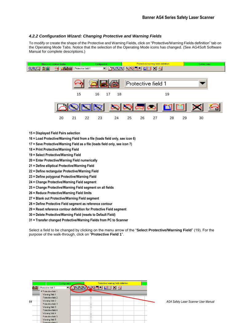
Banner AG4 Series Safety Laser Scanner
64 P/N 144924 rev. A 02/2010 AG4 Safety Laser Scanner User Manual
4.2.2 Configuration Wizard: Changing Protective and Warning Fields
To modify or create the shape of the Protective and Warning Fields, click on ―Protective/Warning Fields definition‖ tab on the Operating Mode Tabs. Notice that the selection of the Operating Mode icons has changed. (See AG4Soft Software Manual for complete descriptions.)
15 = Displayed Field Pairs selection
16 = Load Protective/Warning Field from a file (loads field only, see icon 6)
17 = Save Protective/Warning Field as a file (loads field only, see icon 7)
18 = Print Protective/Warning Field
19 = Select Protective/Warning Field
20 = Enter Protective/Warning Field numerically
21 = Define elliptical Protective/Warning Field
22 = Define rectangular Protective/Warning Field
23 = Define polygonal Protective/Warning Field
24 = Change Protective/Warning Field segment
25 = Change Protective/Warning Field segment on all fields
26 = Reduce Protective/Warning Field limits
27 = Blank out Protective/Warning Field segment
28 = Define Protective Field segment as reference contour
29 = Reset reference contour definition for Protective Field segment
30 = Delete Protective/Warning Field (resets to Default Field)
31 = Transfer changed Protective/Warning Fields from PC to Scanner
Select a field to be changed by clicking on the menu arrow of the ―Select Protective/Warning Field‖ (19). For the purpose of the walk-through, click on ―Protective Field 1‖.
15 16 17 18 19
20 21 22 23 24 25 26 27 28 29 30 31
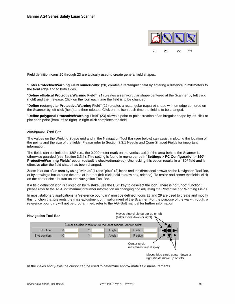
Banner AG4 Series Safety Laser Scanner
Banner AG4 Series User Manual P/N 144924 rev. A 02/2010 65
Field definition icons 20 through 23 are typically used to create general field shapes.
―Enter Protective/Warning Field numerically‖ (20) creates a rectangular field by entering a distance in millimeters to
the front edge and to both sides.
―Define elliptical Protective/Warning Field‖ (21) creates a semi-circular shape centered at the Scanner by left click
(hold) and then release. Click on the icon each time the field is to be changed.
―Define rectangular Protective/Warning Field‖ (22) creates a rectangular (square) shape with on edge centered on
the Scanner by left click (hold) and then release. Click on the icon each time the field is to be changed.
―Define polygonal Protective/Warning Field‖ (23) allows a point-to-point creation of an irregular shape by left-click to
plot each point (from left to right). A right-click completes the field.
Navigation Tool Bar
The values on the Working Space grid and in the Navigation Tool Bar (see below) can assist in plotting the location of the points and the size of the fields. Please refer to Section 3.3.1 Needle and Cone-Shaped Fields for important information.
The fields can be limited to 180º (i.e., the 0.000 meter mark on the vertical axis) if the area behind the Scanner is otherwise guarded (see Section 3.3.1). This setting is found in menu bar path ―Settings > PC Configuration > 190º Protective/Warning Fields‖ option (default is checked/enabled). Unchecking this option results in a 180º field and is
effective after the field shape has been changed.
Zoom in or out of an area by using ―minus‖ (1) and ―plus‖ (2) icons and the directional arrows on the Navigation Tool Bar,
or by drawing a box around the area of interest (left-click, hold to draw box, release). To resize and center the fields, click on the center circle button on the Navigation Tool Bar.
If a field definition icon is clicked on by mistake, use the ESC key to deselect the icon. There is no ―undo‖ function; please refer to the AG4Soft manual for further information on changing and adjusting the Protective and Warning Fields.
In most stationary applications, a ―reference boundary‖ must be defined. Icons 28 and 29 are used to create and modify this function that prevents the miss-adjustment or misalignment of the Scanner. For the purpose of the walk-through, a reference boundary will not be programmed; refer to the AG4Soft manual for further information
Navigation Tool Bar
In the x-axis and y-axis the cursor can be used to determine approximate field measurements.
Moves blue circle cursor up or left (fields move down or right)
Moves blue circle cursor down or right (fields move up or left)
Center circle maximizes field display
20 21 22 23
Banner AG4 Series Safety Laser Scanner
66 P/N 144924 rev. A 02/2010 AG4 Safety Laser Scanner User Manual
The cursor can also be used to click and drag to create a zoom box, in which the values of opposite corners are displayed as the ―Position‖ and ―End position‖. Left-click to ―set‖ a point (Position). Right-click to ―finish‖ (End position).
X and Y values can be used to determine distance between two points by using the formula:
4.2.3 Configuration Wizard: Saving the Configuration
Saving the Entire Configuration, Including the Protective and Warning Fields (.rs file format)
When logged in as an ―Authorized Customer‖ (as noted on the status line tool bar), there are two primary methods to save the configuration, which include the Protective and Warning Fields:
Using the Menu Bar with either the ―Configuration‖ or the ―Protective/Warning Fields definition‖ tabs highlighted (yellow), click on File > Save configuration data as a file, or
Using the ―Configuration‖ Operating Mode Icon ―Save configuration data as a file‖ (7)
A Scanner's configuration file includes the following data:
Administrative data ( file name, application description )
Safety-relevant data, e.g., startup process
Protective Field or Warning Field configuration data (contours and limits)
The AG4Soft program will ask if you want to save a configuration if the ―Measured contour display‖ or ―System data‖ tabs are selected and the configuration has not been previously saved.
Note: For the purposes of the "walk-through," save the configuration file as described above and proceed to Section 4.3.
Saving Only a Protective or Warning Field (.sf file format)
In case a mistake is made and an original starting point is needed or otherwise a record of each field is required, it can be useful to individually save the Protective and Warning Field shapes as they are created.
At an appropriate time, such as before modifying the shapes of the Protective and Warning Fields, the field that is displayed in the ―Select Protective/Warning Field‖ window (19) can be saved by clicking on File > Save Protective/Warning Field as a file‖, or by clicking on the ―Save Protective/Warning Field as a file‖ (17) icon. The ―Protective /Warning Fields definition‖ operating mode tab must be highlighted (yellow) to access this save function.
4.3 Connecting the PC to the Scanner
Note: Ensure power is removed from the Scanner at this point, the AG4-PCD9-xx cordset is not connected to the PC,
and the AG4Soft program is open.
If not previously accomplished in Section 3.6.1, connect the PC Interface cable (AG4-PCD9-xx) to the X2 connector on the Scanner and to the PC serial port. A USB-to-serial adaptor is available (AG4-PCD9USB-1) if the PC does not provide a serial port (see below). If used, connect the AG4-PCD9USB-1 Serial-to-USB adaptor to a version 2.0 USB port and then to the PC Interface cable (AG4-PCD9-xx).
The X1 Machine Interface connection should have been previously made (see Section 3.5). Depending on the situation, it may be required that the machine be disabled with no power available to the machine actuators (Lockout/Tagout regulations may apply, see Sections 3.5 and 3.7).
Apply power to the Scanner. After the Scanner has passed internal testing, communication is established (―AG4 Connection‖ is displayed on the Status line after approximately 30 seconds).
The current configuration automatically loads from the Scanner, the ―Change authorization level‖ dialog box appears (it is recommended to be logged in as an ―Authorized customer‖, default password: bannera), and the status information is ascertained from the Scanner. Review this information and click on ―Exit‖.
At this time the measured area (yellow outline), the Warning Field, and the Protective Field are displayed. The uploaded configuration can be reviewed or manipulated, or a saved configuration can be opened and downloaded to the Scanner as described in Section 4.4. If communications are not established, see Section 4.3.1.
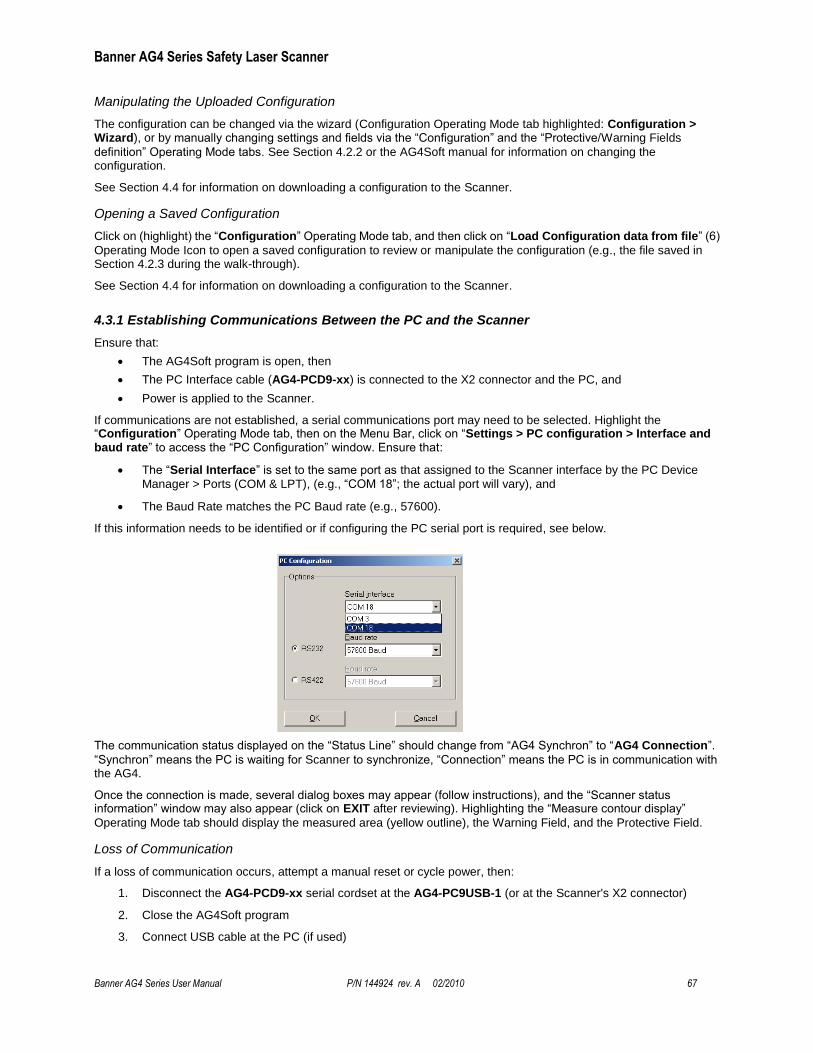
Banner AG4 Series Safety Laser Scanner
Banner AG4 Series User Manual P/N 144924 rev. A 02/2010 67
Manipulating the Uploaded Configuration
The configuration can be changed via the wizard (Configuration Operating Mode tab highlighted: Configuration > Wizard), or by manually changing settings and fields via the ―Configuration‖ and the ―Protective/Warning Fields
definition‖ Operating Mode tabs. See Section 4.2.2 or the AG4Soft manual for information on changing the configuration.
See Section 4.4 for information on downloading a configuration to the Scanner.
Opening a Saved Configuration
Click on (highlight) the ―Configuration‖ Operating Mode tab, and then click on ―Load Configuration data from file‖ (6)
Operating Mode Icon to open a saved configuration to review or manipulate the configuration (e.g., the file saved in Section 4.2.3 during the walk-through).
See Section 4.4 for information on downloading a configuration to the Scanner.
4.3.1 Establishing Communications Between the PC and the Scanner
Ensure that:
The AG4Soft program is open, then
The PC Interface cable (AG4-PCD9-xx) is connected to the X2 connector and the PC, and
Power is applied to the Scanner.
If communications are not established, a serial communications port may need to be selected. Highlight the ―Configuration‖ Operating Mode tab, then on the Menu Bar, click on ―Settings > PC configuration > Interface and baud rate‖ to access the ―PC Configuration‖ window. Ensure that:
The ―Serial Interface‖ is set to the same port as that assigned to the Scanner interface by the PC Device
Manager > Ports (COM & LPT), (e.g., ―COM 18‖; the actual port will vary), and
The Baud Rate matches the PC Baud rate (e.g., 57600).
If this information needs to be identified or if configuring the PC serial port is required, see below.
The communication status displayed on the ―Status Line‖ should change from ―AG4 Synchron‖ to ―AG4 Connection‖.
―Synchron‖ means the PC is waiting for Scanner to synchronize, ―Connection‖ means the PC is in communication with the AG4.
Once the connection is made, several dialog boxes may appear (follow instructions), and the ―Scanner status information‖ window may also appear (click on EXIT after reviewing). Highlighting the ―Measure contour display‖
Operating Mode tab should display the measured area (yellow outline), the Warning Field, and the Protective Field.
Loss of Communication
If a loss of communication occurs, attempt a manual reset or cycle power, then:
1. Disconnect the AG4-PCD9-xx serial cordset at the AG4-PC9USB-1 (or at the Scanner's X2 connector)
2. Close the AG4Soft program
3. Connect USB cable at the PC (if used)
Banner AG4 Series Safety Laser Scanner
68 P/N 144924 rev. A 02/2010 AG4 Safety Laser Scanner User Manual
4. Open AG4Soft program
5. Connect the AG4-PCD9-xx serial cordset to the AG4-PC9USB-1 (or at the X2 connector on the AG4)
Note: If repeated communication loss occurs, check for secure connections, ensure AG4-PCD9-xx cordset (with RS232
communication) are used, and/or shorten the overall cable length.
Configuring the PC Serial Port
If necessary, with the AG4 connected, from the Windows™ ―Start‖ tab, click on Settings > Control Panel > System (System Properties) > Hardware > Device Manager > Ports (COM & LPT)
Click on an available COM port (note the COM port number), select the appropriate Baud rate (bits per second), which should match the Baud rate of the AG4 (default is 57600). Click on ―Port Settings‖ to verify both of these settings.
USB-to-Serial Adaptors
If using a USB-to-serial adaptor, do not connect the adaptor to the Scanner until after the PC has identified the new piece of hardware. If the Scanner is ON and connected to the USB-to-serial adaptor when the USB connection is made to the PC, the PC can misinterpret the data as a PC mouse (causing the mouse cursor to move rapidly around the PC monitor). If this occurs, disconnect the Scanner from the adaptor and follow the instructions for ―Loss of Communication‖ above.
To identify the port the adaptor is connected to, from the Windows™ ―Start‖ tab, click on Settings > Control Panel > System (System Properties) > Hardware > Device Manager > Ports (COM & LPT).
AG4-PCD9USB-1 USB-to-Serial Adaptor
If using the model AG4-PCD9USB-1, select ―Belkin USB-to-Serial Adaptor‖ and note the COM port to which the
device has been assigned. The Baud rate (bits per second) must match the Baud rate of the AG4; default is 57600. Click on ―Port Settings‖ to verify both these settings. If PC Hardware Installation Wizard appears, follow its instructions to install the device drivers.
When using the model AG4-PC9USB-1 USB-to-serial adaptor, keep total cable length to a minimum. Do not use the AG4-PCD9USB-1 with the 10 meter AG4-PCD9-10 cordset. Do not exceed 5 m USB cable length if a USB extension cable is used with the AG4-PCD9USB-1. See http://en-us-support.belkin.com/app/ for further information on the AG4-PCD9USB-1 (BELKIN p/n F5U257) and miscellaneous PC drivers.
4.4 Opening a Configuration File (“.rs” files)
Click on (highlight) the ―Configuration‖ Operating Mode tab, and then click on:
―Load configuration data from a file and transfer to scanner‖ (9) Operating Mode Icon to directly download
a saved configuration,
or
―Load Configuration data from file‖ (6) Operating Mode Icon to open a saved configuration to review or
manipulate the configuration, and then
Click on ―Transfer configuration data from PC to scanner‖ icon (11) Operating Mode Icon.
Note: If following the wizard walk-through, simply click on ―Transfer configuration data from PC to Scanner‖ (11)
Operating Mode Icon.
The same options are accessible from the top Menu Bar; click on Configuration > Load configuration data from a file and transfer to Scanner, or click on File > Load configuration data from file and select an ―.rs‖ file to open and then Configuration > Transfer from PC to Scanner.
Follow the prompts, review and accept the configuration, and then perform the appropriate checkout procedure as described in Section 6 or return to Section 3.6.2 Initial Optical Field Verification.
From the “Protective/Warning Fields Definition” Operating Mode
Both configuration ―.rs‖ files and individual field ―.sf‖ files are accessible when the ―Protective/Warning Fields definition‖ Operating Mode tab is highlighted.

Banner AG4 Series Safety Laser Scanner
Banner AG4 Series User Manual P/N 144924 rev. A 02/2010 69
Configuration ―.rs‖ files are accessible from the top Menu Bar: click on File > Load configuration data from file and select an ―.rs‖ file to open, then click on Protective/Warning Fields > Transfer changed Protective/Warning Fields from PC to Scanner.
Individual fields (.sf files) that have been saved can be accessed and downloaded to the Scanner by the following methods:
Click on (highlight) the Protective/Warning Fields definition Operating Mode tab,
Click on Load Protective/Warning Field from file icon (16); review or manipulate the field as necessary,
Click on Transfer changed Protective/Warning Fields from PC to Scanner icon (31).
Note: The same options are accessible from the top Menu Bar.
Follow the prompts, review and accept the configuration, and then perform the appropriate checkout procedure as described in Section 6 or return to Section 3.6.2 Initial Optical Field Verification.
4.5 Downloading a Configuration to the Scanner
Note: Communications must be established with the AG4 at this time (see 4.3) and the Authorization Level selected must be ―Authorized Customer‖.
With a configuration open (and following the walk-through), click on (highlight) the ―Configuration‖ Operating Mode tab, and then click on ―Transfer configuration data from PC to Scanner‖ (11) Operating Mode Icon. Review the configuration and the fields as they are displayed, and if correct, click on ―Accept‖. After the transfer of the configuration data has been confirmed, click OK.
If the fields are clear, the Scanner either should be awaiting a reset or should have automatically reset with the OSSD output ON. (Note: This finishes the wizard walk-through demonstration.)
Perform the appropriate checkout procedure as described in Section 6 or return to Section 3.6.2 Initial Optical Field Verification.
4.6 Start/Restart Interlock (Reset) Procedures
4.6.1 Resetting the System
System resets are typically performed using an external reset switch. This switch must be located as discussed in Section 3.3.7.
If supervisory control of the reset switch is required, a key switch may be used, with the key kept in the possession of a Designated or Qualified Person. Using a key switch will also provide some level of personal control, since the key may be removed from the switch. This will hinder a reset while the key is under the control of an individual, but must not be relied upon solely to guard against accidental or unauthorized reset. (Spare keys in the possession of others or additional personnel entering the safeguarded area unnoticed may create a hazardous situation.)
The Restart (Reset) input, pin 2 (Violet wire), provides for a manual reset input signal.
The Scanner requires a manual reset to clear a Start/Restart Interlock condition and resume operation following a stop command. Internal Lockout conditions also require a manual reset to return to Run mode after the failure has been corrected. See Section 1.12.1 for more information.
Reset Routine
To reset the Scanner, close the reset switch for ¼ to 5 seconds, and then open it. Closing the reset switch too long will cause the sensor to ignore the reset request; the switch must be closed from ¼ second to 5 seconds, but no longer.
4.7 Status Indicators
A variety of status indicators are clearly visible on the face of the Scanner. See Section 1.1 for information on the Status Display, Section 3.6.2 for indications during the Trip test, and Section 5 for diagnostic indications and codes.
4.8 Normal Operation
Four configurations affect the AG4 behavior at power-up and during Run mode:

Banner AG4 Series Safety Laser Scanner
70 P/N 144924 rev. A 02/2010 AG4 Safety Laser Scanner User Manual
Restart Interlock with Start Interlock (Manual Reset)
Automatic Restart Interlock with Start Interlock (Automatic Reset with manual power-up)
Automatic Restart Interlock with Automatic Start (Automatic Reset)
Automatic Restart Interlock with Start Test (Automatic Reset with test at power-up)
In any case, the clearing of the Protected Field (PF), or the reset of a start/restart interlock condition MUST NOT initiate dangerous machine motion. Machine control circuitry must be designed so that one or more initiation devices
must be engaged (i.e., a conscious act) to start the machine – in addition to the Scanner turning ON its safety outputs (OSSD1 and OSSD2). See Section 1.12.1
4.8.1 System Power-Up
The Scanner will power up in one of three ways, depending on the Start/Restart (reset) Interlock configuration (1.12.1) and whether the Start Test is enabled (1.12.2). These options will be limited by the selected application (see Section 3).
When power is applied, the Scanner conducts self-tests to detect critical internal faults, determine configuration settings, and prepare for operation, which can take up to 30 seconds (typical).
Start Interlock (Manual Power-up): If no faults are detected during the self-test, the Scanner enters Run
mode and evaluates the Protective and Warning Fields. If no obstructions are detected, the Yellow Start/Restart (Reset) indicator (LED #5 in Figure 1-3) to indicate the Scanner is waiting for a manual reset to turn ON the OSSD outputs.
Automatic Start (Automatic Reset): If no faults are detected during the self-test, the Scanner enters Run
mode and evaluates the Protective and Warning Fields. If no obstructions are detected, the OSSDs turn ON after the restart delay time (160 ms to 10160 ms in 40 ms increments) and the two Green indicators (LEDs #1 and #3 in Figure 1-3) turn ON. No manual reset operation is required.
Start Test (Test at Power-up): If no faults are detected during the self-test, the Scanner waits for the
Protective Field to be interrupted by an object equal to or greater than the configured resolution (e.g., a test piece). Then, after the field is clear the OSSD outputs turn ON. The Protective Field must be clear before the test is performed, or all obstructions must be removed and then the test can be performed. No manual reset operation is required.
4.8.2 During Run Mode
The Scanner can be configured for two output configurations:
Restart Interlock (Manual Reset): When the Protective Field becomes interrupted by an object larger than
the configured resolution the OSSD outputs turn OFF within the configured response time (see 4.6). If the Protective Field then becomes clear, the LED #1 indicator will be GREEN and the YELLOW Start/Restart (Reset) indicator (LED #5 on Figure 1-3) will indicate the Scanner is waiting for a manual reset to turn ON the OSSD outputs. The OSSD outputs come back ON only when the Protective Field is clear and after a manual reset. This is also known as Latch Output mode.
Automatic Restart Interlock (Automatic Reset): When the Protective Field becomes interrupted by an
object larger than the configured resolution the OSSD outputs turn OFF within the configured response time (see 4.6). If the Protective Field then becomes clear, OSSD outputs come back ON. No resets of any kind are
needed. This is also known as Trip Output mode.
Internal Faults (Lockouts)
If a critical fault(s) is detected, the Scanner enters a lockout condition, the OSSD outputs remain OFF and diagnostic information is displayed on the LED display (LED #5 flashes at a 4Hz rate) and is available via the AG4Soft program. To access diagnostic information highlight the ―System Data‖ Operating tab and click on menu bar path System Data > Display the Scanner’s diagnostics list. See Section 5 for resolution of error/fault conditions.
4.9 Determining Response Time
The Scanner's response time is the time needed to switch OFF its OSSD outputs, after an object is detected. Two response time options are provided in the AG4Soft program and must be noted to determine the Safety Distance (Minimum Distance). Either of the two response times can be configured for a time between 80 ms - 640 ms, in 40 ms increments.
Banner AG4 Series Safety Laser Scanner
Banner AG4 Series User Manual P/N 144924 rev. A 02/2010 71
Protective Field (PF) response time: Time until the Scanner switches off the OSSD 1 and OSSD 2 safety
outputs or switching function (Default = 80 ms).
Warning Field (WF) response time: Time until the Scanner switches off the Alarm output (Default = 80 ms).
To determine the configured response times, establish communications with the Scanner, at which time the status information should automatically upload from the Scanner. The Protective Field response time and the Warning Field response time will be listed in the ―Scanner status information‖ dialog box. A text file can be created or the information can be sent to a printer.
If the ―Scanner status information‖ dialog box does not appear or otherwise needs to be accessed, click on (highlight) the System data Operating Mode tab, and then on the Menu Bar, click on System data > Transfer information from Scanner to PC to access the information.
4.10 Periodic Checkout Requirements
To ensure continued reliable operation, the System must be checked out periodically. See Section 6 for more information.
At every shift change, power-up and machine setup change, the Daily checkout should be performed; this
checkout may be performed by a Designated or Qualified Person (see Section 6.3 and the Daily Checkout Card for the procedure).
Semi-annually, the Scanner and its interface to the guarded machine should be thoroughly checked out; this checkout
must be performed by a Qualified Person (see Section 6.4 and the Semi-Annual Checkout Card for the procedure). A copy of these test results should be posted on or near the machine.
Whenever changes are made to the System (either a new configuration of the Scanner or changes to the machine),
the Commissioning Checkout should be performed; see Section 6.2.
WARNING . . . VERIFY PROPER OPERATION
It is the user’s responsibility to verify proper operation, on a regular basis, as instructed in Section 6. Failure to do so can result in
undetected problems, which if not corrected, can result in serious bodily injury or death.
Banner AG4 Series Safety Laser Scanner
72 P/N 144924 rev. A 02/2010 AG4 Safety Laser Scanner User Manual
5. Troubleshooting and Maintenance
The Scanner uses three diagnostics levels to quickly resolve errors. Proceed in steps to resolve an error:
1. Determine the Scanner’s status, signaled via LEDs and remove the errors with the specified measures listed in the diagnostic Key.
2. Read the diagnostics list with the configuration and diagnostics software and remove the errors with the aid of the solution provided.
3. Create a service file with the configuration and diagnostics software and send this service file for remote diagnostics to Banner (see AG4soft Software Instruction Manual for more information).
Refer to Figure 5-1 for LED names and locations.
5.1 Troubleshooting Lockout Conditions
A Lockout condition causes all of the Scanner OSSD outputs to turn or remain OFF, sending a stop signal to the guarded machine. Diagnostic error codes are available to assist in the identification of the cause(s) of lockouts.
The Scanner provides easy methods for determining operating problems. A Lockout condition is indicated by LED #5 (YELLOW) on the LED display flashing at a 4Hz rate and diagnostic information is available via the AG4Soft program. To access diagnostic information highlight the ―System Data‖ Operating tab and click on menu bar path ―System Data > Display the Scanner’s diagnostics list‖.
See Section 5.1.1 and 5.1.2 for diagnostic information and resolution of error/fault conditions.
See Section 5.2 for communication errors and loss of communication.
Recovery Procedures
To recover from a Lockout condition, all errors must be corrected and a reset routine must be performed as described below or power must be cycled (power the Scanner down, wait a second or two, then power it up). NOTE: See Section 4.5 for power-up and Run mode behavior.
Reset Routine
To reset the Scanner, close the reset switch for ¼ to 5 seconds, and then open it. Closing the reset switch too long will cause the sensor to ignore the reset request; the switch must be closed from ¼ second to 5 seconds, but no longer (per Section 4.5).
5.1.1 Scanner LED Status Display
WARNING . . . SHUT DOWN MACHINERY BEFORE SERVICING
The machinery to which the Scanner is connected must not be operating at any time during major service or maintenance. This may
require lockout/tagout procedures (refer to OSHA1910.147, ANSI Z244-1, or the appropriate standard for controlling hazardous energy). Servicing
the Scanner while the hazardous machinery is operational could result in serious bodily injury or death.
WARNING . . . LOCKOUTS AND POWER FAILURES
Power failures and Lockout conditions are indication of a problem and must be investigated immediately by a Qualified Person. Attempts to continue to operate machinery by bypassing the Scanner or other safeguards is dangerous and could result in serious bodily injury or death.
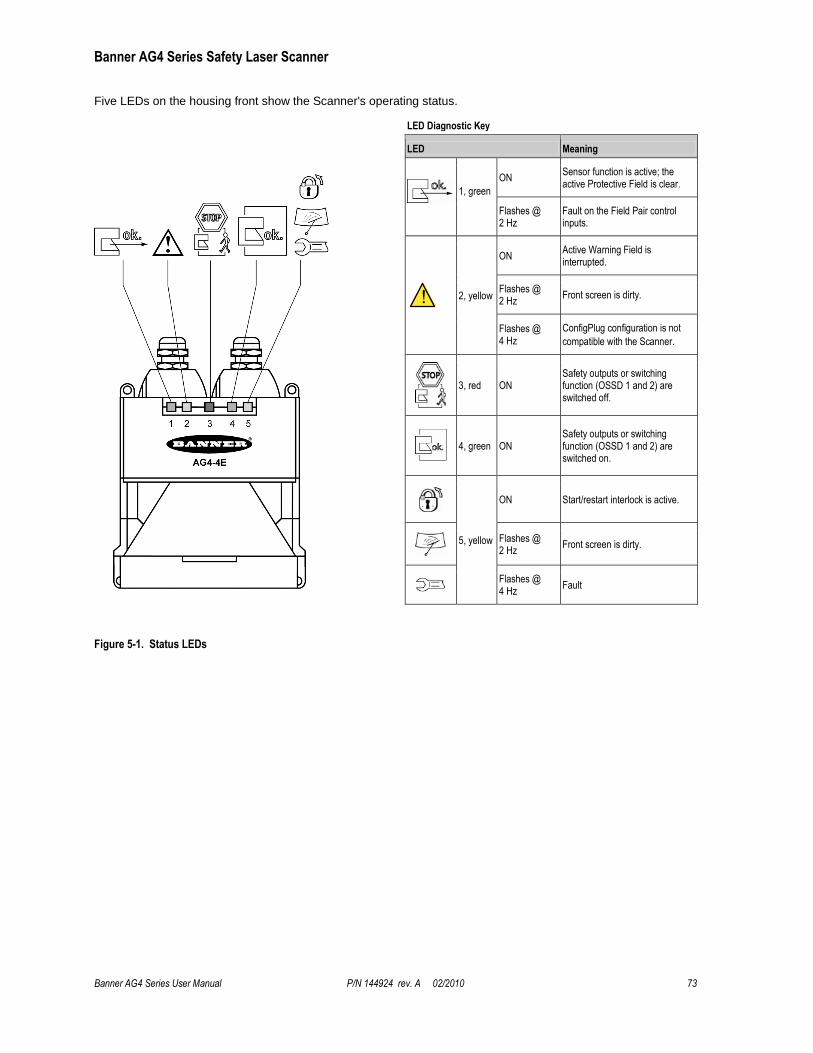
Banner AG4 Series Safety Laser Scanner
Banner AG4 Series User Manual P/N 144924 rev. A 02/2010 73
Five LEDs on the housing front show the Scanner's operating status.
LED Diagnostic Key
LED Meaning
1, green
ON Sensor function is active; the active Protective Field is clear.
Flashes @ 2 Hz
Fault on the Field Pair control inputs.
2, yellow
ON Active Warning Field is interrupted.
Flashes @ 2 Hz
Front screen is dirty.
Flashes @ 4 Hz
ConfigPlug configuration is not
compatible with the Scanner.
3, red ON Safety outputs or switching function (OSSD 1 and 2) are switched off.
4, green ON Safety outputs or switching function (OSSD 1 and 2) are switched on.
5, yellow
ON Start/restart interlock is active.
Flashes @ 2 Hz
Front screen is dirty.
Flashes @ 4 Hz
Fault
Figure 5-1. Status LEDs
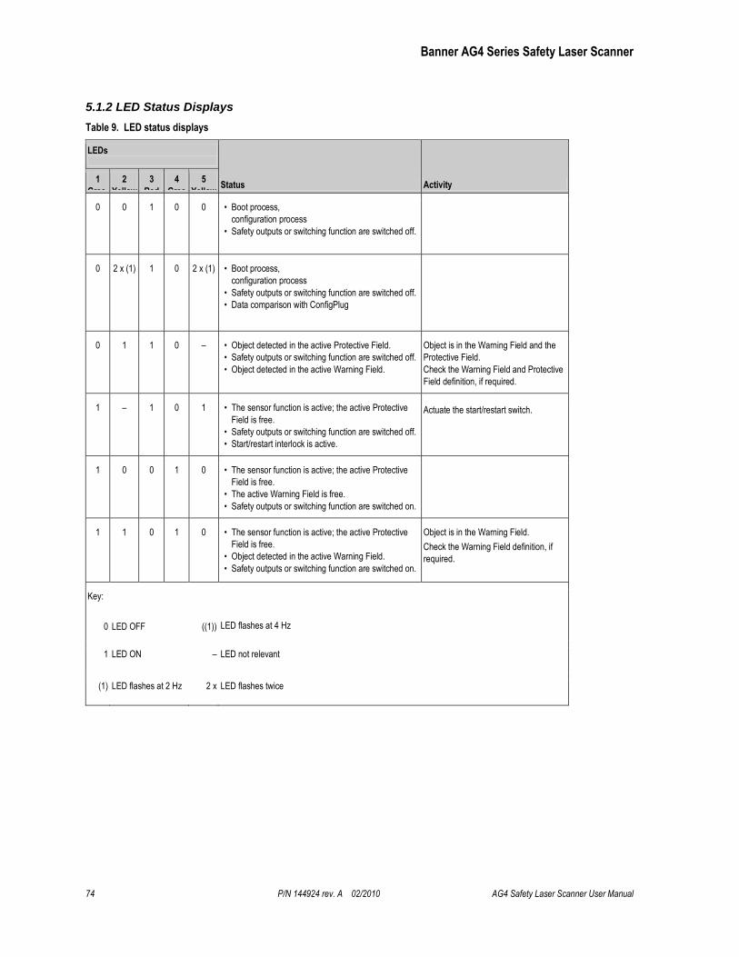
Banner AG4 Series Safety Laser Scanner
74 P/N 144924 rev. A 02/2010 AG4 Safety Laser Scanner User Manual
5.1.2 LED Status Displays
Table 9. LED status displays
LEDs
Status Activity
1
Gree
n
2
Yellow
3
Red
4
Gree
n
5
Yellow
0 0 1 0 0 • Boot process,
configuration process
• Safety outputs or switching function are switched off.
0 2 x (1) 1 0 2 x (1) • Boot process,
configuration process
• Safety outputs or switching function are switched off.
• Data comparison with ConfigPlug
0 1 1 0 – • Object detected in the active Protective Field.
• Safety outputs or switching function are switched off.
• Object detected in the active Warning Field.
Object is in the Warning Field and the
Protective Field.
Check the Warning Field and Protective
Field definition, if required.
1 – 1 0 1 • The sensor function is active; the active Protective
Field is free.
• Safety outputs or switching function are switched off.
• Start/restart interlock is active.
Actuate the start/restart switch.
1 0 0 1 0 • The sensor function is active; the active Protective
Field is free.
• The active Warning Field is free.
• Safety outputs or switching function are switched on.
1 1 0 1 0 • The sensor function is active; the active Protective
Field is free.
• Object detected in the active Warning Field.
• Safety outputs or switching function are switched on.
Object is in the Warning Field.
Check the Warning Field definition, if
required.
Key:
0 LED OFF ((1)) LED flashes at 4 Hz
1 LED ON – LED not relevant
(1) LED flashes at 2 Hz 2 x LED flashes twice
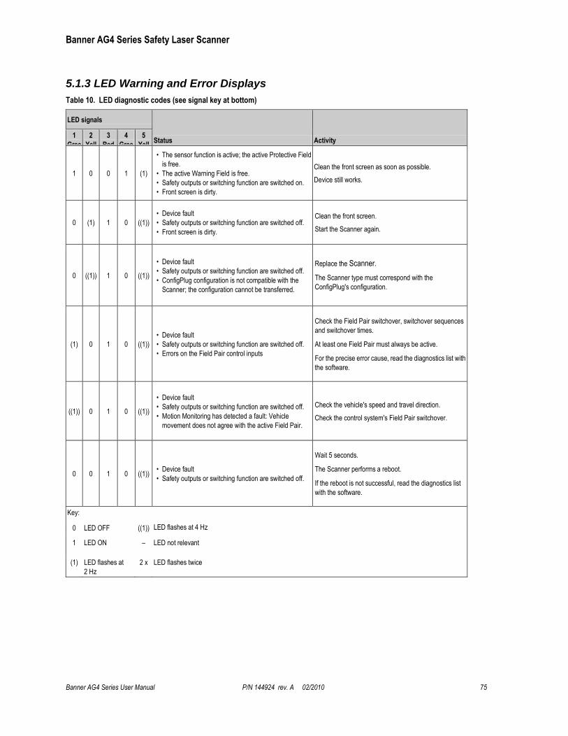
Banner AG4 Series Safety Laser Scanner
Banner AG4 Series User Manual P/N 144924 rev. A 02/2010 75
5.1.3 LED Warning and Error Displays
Table 10. LED diagnostic codes (see signal key at bottom)
LED signals
Status Activity 1
Gree
n
2
Yell
ow
3
Red
4
Gree
n
5
Yell
ow
1 0 0 1 (1)
• The sensor function is active; the active Protective Field
is free.
• The active Warning Field is free.
• Safety outputs or switching function are switched on.
• Front screen is dirty.
Clean the front screen as soon as possible.
Device still works.
0 (1) 1 0 ((1))
• Device fault
• Safety outputs or switching function are switched off.
• Front screen is dirty.
Clean the front screen.
Start the Scanner again.
0 ((1)) 1 0 ((1))
• Device fault
• Safety outputs or switching function are switched off.
• ConfigPlug configuration is not compatible with the
Scanner; the configuration cannot be transferred.
Replace the Scanner.
The Scanner type must correspond with the
ConfigPlug's configuration.
(1) 0 1 0 ((1))
• Device fault
• Safety outputs or switching function are switched off.
• Errors on the Field Pair control inputs
Check the Field Pair switchover, switchover sequences
and switchover times.
At least one Field Pair must always be active.
For the precise error cause, read the diagnostics list with
the software.
((1)) 0 1 0 ((1))
• Device fault
• Safety outputs or switching function are switched off.
• Motion Monitoring has detected a fault: Vehicle
movement does not agree with the active Field Pair.
Check the vehicle's speed and travel direction.
Check the control system's Field Pair switchover.
0 0 1 0 ((1)) • Device fault
• Safety outputs or switching function are switched off.
Wait 5 seconds.
The Scanner performs a reboot.
If the reboot is not successful, read the diagnostics list
with the software.
Key:
0 LED OFF ((1)) LED flashes at 4 Hz
1 LED ON – LED not relevant
(1) LED flashes at
2 Hz
2 x LED flashes twice
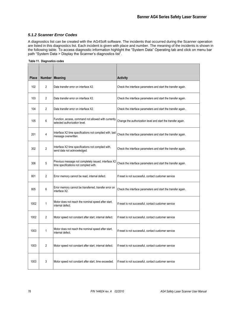
Banner AG4 Series Safety Laser Scanner
76 P/N 144924 rev. A 02/2010 AG4 Safety Laser Scanner User Manual
5.1.2 Scanner Error Codes
A diagnostics list can be created with the AG4Soft software. The incidents that occurred during the Scanner operation are listed in this diagnostics list. Each incident is given with place and number. The meaning of the incidents is shown in the following table. To access diagnostic information highlight the ―System Data‖ Operating tab and click on menu bar path ―System Data > Display the Scanner’s diagnostics list‖.
Table 11. Diagnostics codes
Place Number Meaning Activity
102 2 Data transfer error on interface X2. Check the interface parameters and start the transfer again.
103 2 Data transfer error on interface X2. Check the interface parameters and start the transfer again.
104 2 Data transfer error on interface X2. Check the interface parameters and start the transfer again.
105 6 Function, access, command not allowed with currently selected authorization level.
Change the authorization level and start the transfer again.
201 4 Interface X2 time specifications not complied with, last message overwritten.
Check the interface parameters and start the transfer again.
302 2 Interface X2 time specifications not complied with, send data not acknowledged.
Check the interface parameters and start the transfer again.
306 5 Previous message not completely issued, interface X2 time specifications not complied with.
Check the interface parameters and start the transfer again.
801 2 Error memory cannot be read, internal defect. If reset is not successful, contact customer service
805 6 Error memory cannot be transferred, transfer error on interface X2.
Check the interface parameters and start the transfer again.
1002 1 Motor does not reach the nominal speed after start, internal defect.
If reset is not successful, contact customer service
1002 2 Motor speed not constant after start, internal defect. If reset is not successful, contact customer service
1003 1 Motor does not reach the nominal speed after start, internal defect.
If reset is not successful, contact customer service
1003 2 Motor speed not constant after start, internal defect. If reset is not successful, contact customer service
1003 3 Motor speed not constant after start, time exceeded. If reset is not successful, contact customer service

Banner AG4 Series Safety Laser Scanner
Banner AG4 Series User Manual P/N 144924 rev. A 02/2010 77
Place Number Meaning Activity
1110 4 Safety outputs or switching function (OSSDs) cannot be switched, short-circuit with 0 V DC or +24 V DC.
Check the connection/wiring of the OSSDs.
1110 5 Safety outputs or switching function (OSSDs) cannot be switched, short-circuit between OSSD1 and OSSD2.
Check the connection/wiring of the OSSDs.
1110 6 Safety outputs or switching function (OSSDs) cannot be switched, short-circuit with 0 V DC or +24 V DC.
Check the connection/wiring of the OSSDs.
1111 7 Short-circuit between safety outputs or switching function OSSD1 and OSSD2
Check the connection/wiring of the OSSDs.
1111 8 Short-circuit of one safety output or switching function (OSSD) with 0 V DC.
Check the connection/wiring of the OSSDs.
1111 9 Short-circuit of one safety output or switching function (OSSD) with +24 V DC.
Check the connection/wiring of the OSSDs.
1606 4 Angle error detected, poss. rotation of the sensor housing; switch-off and reset followed.
If reset is not successful, contact customer service
1607 5 Angle error detected, poss. rotation of the sensor housing; switch-off and reset followed.
If reset is not successful, contact customer service
1608 8 Motor speed not constant during operation, poss. rotation of the sensor housing.
If reset is not successful, contact customer service
1608 9 Motor speed not constant during operation, poss. rotation of the sensor housing.
If reset is not successful, contact customer service
1608 10 Motor speed not constant during operation, poss. rotation of the sensor housing.
If reset is not successful, contact customer service
1705 1 Signal of a light beam safety device of the window monitoring below the bottom limit, dirty front screen.
Clean the front screen
1705 2 Signal of a light beam safety device of the window monitoring below the bottom limit, oil/grease on the front screen
Clean the front screen
1906 1 Safety outputs or switching function (OSSDs) cannot be switched, internal or external short-circuit.
Check the connection/wiring of the OSSDs. If reset is not successful, contact customer service
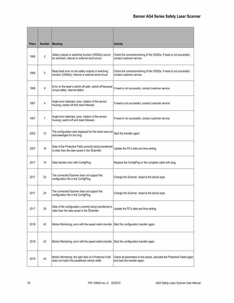
Banner AG4 Series Safety Laser Scanner
78 P/N 144924 rev. A 02/2010 AG4 Safety Laser Scanner User Manual
Place Number Meaning Activity
1906 2 Safety outputs or switching function (OSSDs) cannot be switched, internal or external short-circuit.
Check the connection/wiring of the OSSDs. If reset is not successful, contact customer service
1906 5 Read back error on the safety outputs or switching function (OSSDs), internal or external short-circuit.
Check the connection/wiring of the OSSDs. If reset is not successful, contact customer service
1906 6 Error on the laser's switch-off path, switch-off because of eye safety, internal defect
If reset is not successful, contact customer service
1907 4 Angle error detected, poss. rotation of the sensor housing; switch-off and reset followed.
If reset is not successful, contact customer service
1907 7 Angle error detected, poss. rotation of the sensor housing; switch-off and reset followed.
If reset is not successful, contact customer service
2002 12 The configuration data displayed for the check was not acknowledged for too long.
Start the transfer again.
2007 18 Date of the Protective Field currently being transferred
is older than the date saved in the Scanner. Update the PC's date and time setting.
2017 19 Data transfer error with ConfigPlug Replace the ConfigPlug or the complete cable with plug.
2017 23 The connected Scanner does not support the configuration file in the ConfigPlug.
Change the Scanner, observe the device type.
2017 24 The connected Scanner does not support the configuration file in the ConfigPlug.
Change the Scanner, observe the device type.
2017 26 Date of the configuration currently being transferred is
older than the date saved in the Scanner. Update the PC's date and time setting.
2018 42 Motion Monitoring, error with the speed matrix transfer. Start the configuration transfer again.
2018 43 Motion Monitoring, error with the speed matrix transfer. Start the configuration transfer again.
2018 44 Motion Monitoring, the right side of a Protective Field does not match the predefined vehicle width.
Check all parameters in the wizard, calculate the Protective Fields again and start the transfer again.
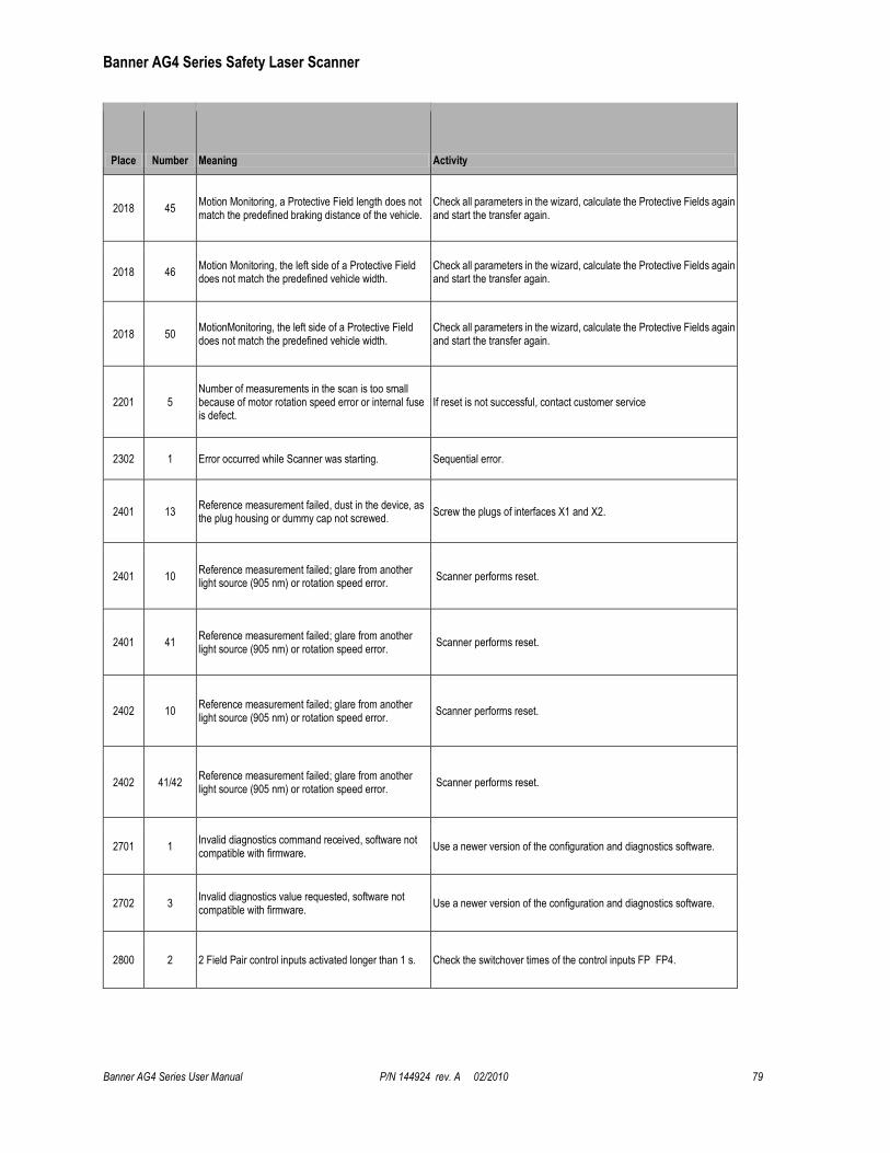
Banner AG4 Series Safety Laser Scanner
Banner AG4 Series User Manual P/N 144924 rev. A 02/2010 79
Place Number Meaning Activity
2018 45 Motion Monitoring, a Protective Field length does not match the predefined braking distance of the vehicle.
Check all parameters in the wizard, calculate the Protective Fields again and start the transfer again.
2018 46 Motion Monitoring, the left side of a Protective Field does not match the predefined vehicle width.
Check all parameters in the wizard, calculate the Protective Fields again and start the transfer again.
2018 50 MotionMonitoring, the left side of a Protective Field does not match the predefined vehicle width.
Check all parameters in the wizard, calculate the Protective Fields again and start the transfer again.
2201 5 Number of measurements in the scan is too small because of motor rotation speed error or internal fuse is defect.
If reset is not successful, contact customer service
2302 1 Error occurred while Scanner was starting. Sequential error.
2401 13 Reference measurement failed, dust in the device, as the plug housing or dummy cap not screwed.
Screw the plugs of interfaces X1 and X2.
2401 10 Reference measurement failed; glare from another light source (905 nm) or rotation speed error.
Scanner performs reset.
2401 41 Reference measurement failed; glare from another light source (905 nm) or rotation speed error.
Scanner performs reset.
2402 10 Reference measurement failed; glare from another light source (905 nm) or rotation speed error.
Scanner performs reset.
2402 41/42 Reference measurement failed; glare from another light source (905 nm) or rotation speed error.
Scanner performs reset.
2701 1 Invalid diagnostics command received, software not compatible with firmware.
Use a newer version of the configuration and diagnostics software.
2702 3 Invalid diagnostics value requested, software not compatible with firmware.
Use a newer version of the configuration and diagnostics software.
2800 2 2 Field Pair control inputs activated longer than 1 s. Check the switchover times of the control inputs FP FP4.
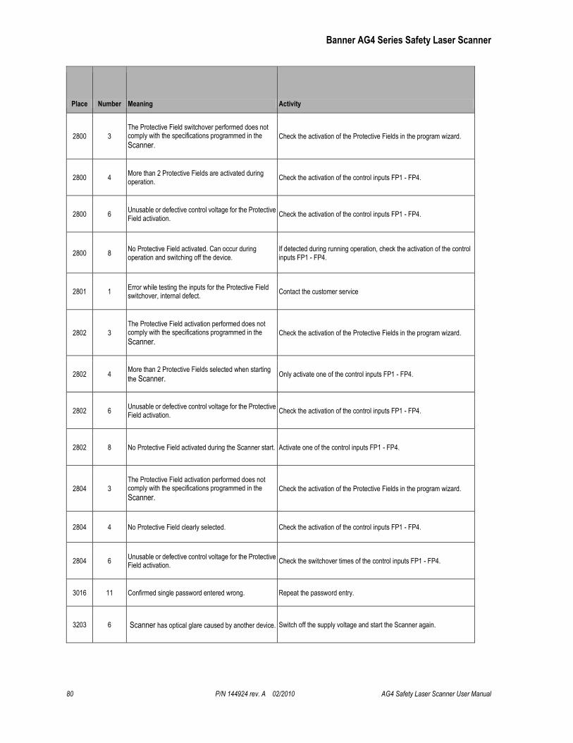
Banner AG4 Series Safety Laser Scanner
80 P/N 144924 rev. A 02/2010 AG4 Safety Laser Scanner User Manual
Place Number Meaning Activity
2800 3
The Protective Field switchover performed does not comply with the specifications programmed in the
Scanner. Check the activation of the Protective Fields in the program wizard.
2800 4 More than 2 Protective Fields are activated during operation.
Check the activation of the control inputs FP1 - FP4.
2800 6 Unusable or defective control voltage for the Protective Field activation.
Check the activation of the control inputs FP1 - FP4.
2800 8 No Protective Field activated. Can occur during operation and switching off the device.
If detected during running operation, check the activation of the control inputs FP1 - FP4.
2801 1 Error while testing the inputs for the Protective Field switchover, internal defect.
Contact the customer service
2802 3
The Protective Field activation performed does not comply with the specifications programmed in the
Scanner. Check the activation of the Protective Fields in the program wizard.
2802 4 More than 2 Protective Fields selected when starting
the Scanner. Only activate one of the control inputs FP1 - FP4.
2802 6 Unusable or defective control voltage for the Protective Field activation.
Check the activation of the control inputs FP1 - FP4.
2802 8 No Protective Field activated during the Scanner start. Activate one of the control inputs FP1 - FP4.
2804 3
The Protective Field activation performed does not comply with the specifications programmed in the
Scanner. Check the activation of the Protective Fields in the program wizard.
2804 4 No Protective Field clearly selected. Check the activation of the control inputs FP1 - FP4.
2804 6 Unusable or defective control voltage for the Protective Field activation.
Check the switchover times of the control inputs FP1 - FP4.
3016 11 Confirmed single password entered wrong. Repeat the password entry.
3203 6 Scanner has optical glare caused by another device. Switch off the supply voltage and start the Scanner again.
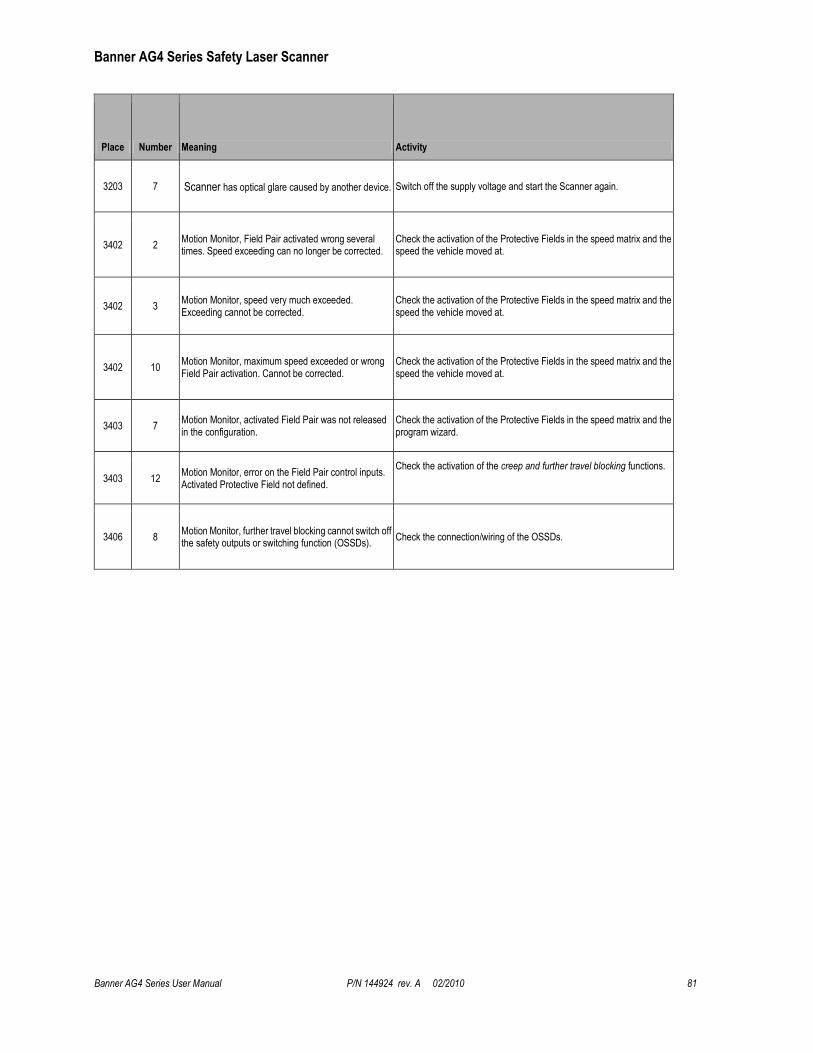
Banner AG4 Series Safety Laser Scanner
Banner AG4 Series User Manual P/N 144924 rev. A 02/2010 81
Place Number Meaning Activity
3203 7 Scanner has optical glare caused by another device. Switch off the supply voltage and start the Scanner again.
3402 2 Motion Monitor, Field Pair activated wrong several times. Speed exceeding can no longer be corrected.
Check the activation of the Protective Fields in the speed matrix and the speed the vehicle moved at.
3402 3 Motion Monitor, speed very much exceeded. Exceeding cannot be corrected.
Check the activation of the Protective Fields in the speed matrix and the speed the vehicle moved at.
3402 10 Motion Monitor, maximum speed exceeded or wrong Field Pair activation. Cannot be corrected.
Check the activation of the Protective Fields in the speed matrix and the speed the vehicle moved at.
3403 7 Motion Monitor, activated Field Pair was not released in the configuration.
Check the activation of the Protective Fields in the speed matrix and the program wizard.
3403 12 Motion Monitor, error on the Field Pair control inputs. Activated Protective Field not defined.
Check the activation of the creep and further travel blocking functions.
3406 8 Motion Monitor, further travel blocking cannot switch off the safety outputs or switching function (OSSDs).
Check the connection/wiring of the OSSDs.

Banner AG4 Series Safety Laser Scanner
82 P/N 144924 rev. A 02/2010 AG4 Safety Laser Scanner User Manual
5.2 Communication Errors and Loss of Communication
See Section 4.3 ―Connecting to the Scanner‖ and Section 4.3.1 ―Establishing Communications Between the PC and the Scanner‖ for general information concern such items as ―Configuring the PC Serial Port‖, ―Loss of Communications‖, and USB-to-serial adaptors, including the AG4-PCD9USB-1.
Only use AG4-PCD9-.. cordsets or standard RS232 extension cordsets with SUB-D9 connectors to connect to the AG4
X2 PC Interface connector. Do not exceed 10 meters (30’) of cable length or communication errors may occur.
When using a USB-to-serial adaptor, keep total cable length to a minimum. Do not use the AG4-PCD9USB-1 with the 10 meter AG4-PCD9-10 cordset. Do not exceed 5 m USB cable length if an USB extension cable is used with a USB-to-serial adaptor. See http://en-us-support.belkin.com/app/ for further information on the AG4-PCD9USB-1
(BELKIN p/n F5U257) and miscellaneous PC drivers.
5.2.1 AG4Soft Pop-up Error Messages
Examples of pop-up error messages that indicate communication problems or a lockout include:
Banner AG4 Series Safety Laser Scanner
Banner AG4 Series User Manual P/N 144924 rev. A 02/2010 83
5.3 Electrical and Optical Noise
The Scanner is designed and manufactured to be highly resistant to electrical and optical noise and to operate reliably in industrial settings. However, serious electrical and/or optical noise may cause a random OFF state of the OSSDs. In very extreme electrical noise cases, a Lockout is possible.
If random nuisance noise problems occur, check the following:
Poor connection between the Machine Interface (X1) cable shield and earth ground;
Optical interference from adjacent safety laser scanners or other photoelectrics; or
Scanner input or output wires routed too close to ―noisy‖ wiring.
Note: Do not directly ground the Scanner housing. Make only those connections as described in Section 3.
All Scanner wiring is low voltage; running these wires alongside power wires, motor/servo wires, or other high-voltage wiring can inject noise into the Scanner. It is good wiring practice (and may be required by code) to isolate Scanner wires from high-voltage wires. The Banner model BT-1 Beam Tracker (see Banner catalog or website) is a very good tool for
detecting electrical noise. It can be used to detect electrical transient spikes and surges.
Checking for sources of electrical noise: Turn off the Scanner and cover the lens of the BT-1 with electrical tape to
block optical light from getting into the receiver lens. Press the ―RCV‖ button on the BT-1 and position the Beam Tracker on the wires going to the Scanner or any other nearby wires. Noise caused by the switching of inductive loads should be addressed by installing proper transient suppression across the load.
Checking for sources of optical noise: Turn off the Scanner. Then use a Banner BT-1 Beam Tracker to check for light
at the AG4 front screen (window) by press the ―RCV‖ button on the BT-1 and moving across the full length of the window with the BT-1 lenses facing away from the AG4. If the BT-1’s indicator lights, check for light from other sources (e.g., other safety laser scanners) by ―tracking down‖ the emitted light, using the BT-1.
5.4 Servicing and Maintenance
5.4.1 Removing the Scanner from the Machine
If the Scanner is to be removed from the machine and stored for a period of time, it is recommended to restore the Scanner to the default configuration settings (see AG4soft Software Instruction Manual).
5.4.2 Cleaning the Front Screen (Window) and Scatter Screens
Clean the Scanner’s front and scatter screens regularly, at a frequency depending on the surrounding environmental conditions, and using the recommended materials. Use only the AG4-CLN.. cleaning kit specified in Section 2,
consisting of approved cleanser and cleaning cloths. Do not use scouring pads or cloths that can cause scratching (e.g., paper towels). Never use solvents that can damage the plastic materials. The cleaning procedure depends on the type and degree of contamination; see Table 12.
Table 12. Cleaning the Scanner front screen
Contamination Cleaning
Particles, loose, scouring Vacuum without touching or blow away softly, oil-free
Wipe free in one swipe with cleaning cloth
Particles, loose, non-scouring Vacuum without touching or blow away softly
Wipe free in one swipe with cleaning cloth
Particles, sticking Wet with cloth soaked in AG4 cleanser
Wipe free in one swipe with cleaning cloth
Particles, statically charged Vacuum without touching
Wipe free in one swipe with cleaning cloth soaked with AG4 cleanser
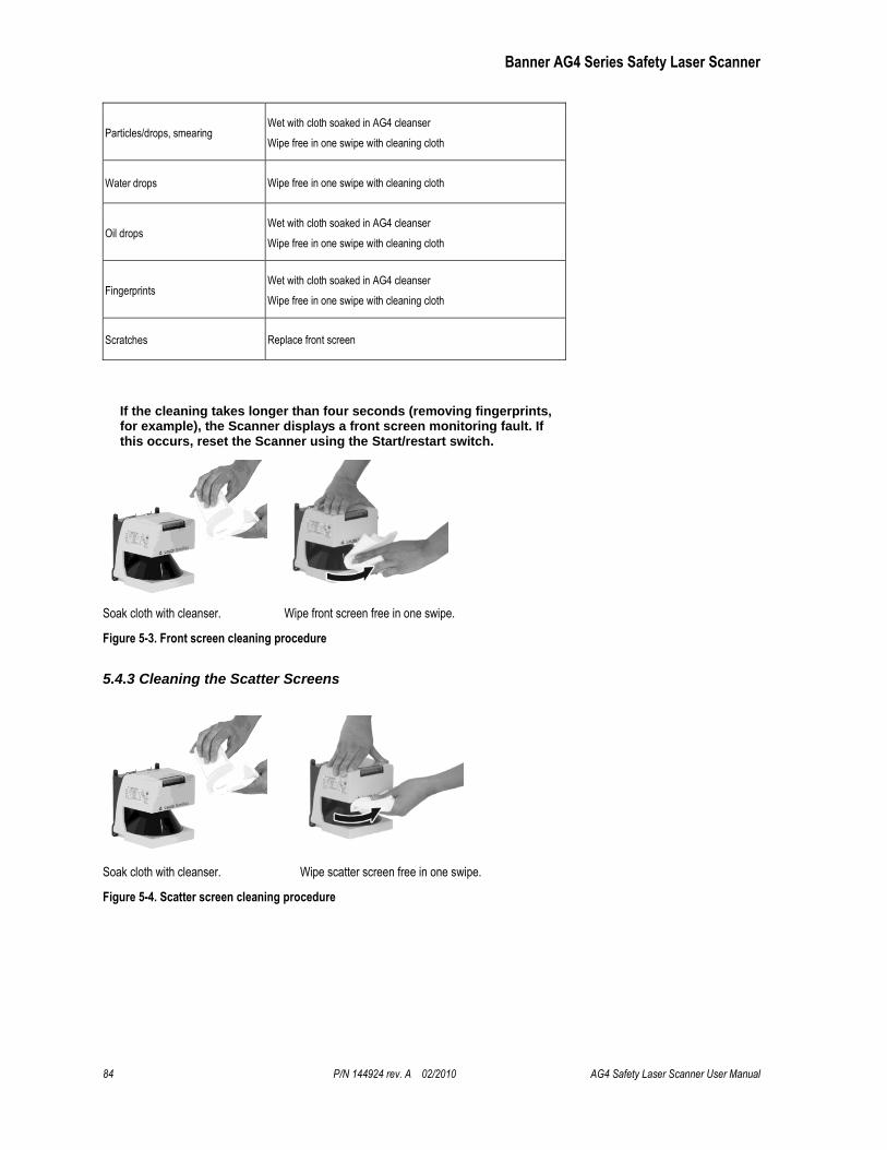
Banner AG4 Series Safety Laser Scanner
84 P/N 144924 rev. A 02/2010 AG4 Safety Laser Scanner User Manual
Particles/drops, smearing Wet with cloth soaked in AG4 cleanser
Wipe free in one swipe with cleaning cloth
Water drops Wipe free in one swipe with cleaning cloth
Oil drops Wet with cloth soaked in AG4 cleanser
Wipe free in one swipe with cleaning cloth
Fingerprints Wet with cloth soaked in AG4 cleanser
Wipe free in one swipe with cleaning cloth
Scratches Replace front screen
If the cleaning takes longer than four seconds (removing fingerprints, for example), the Scanner displays a front screen monitoring fault. If this occurs, reset the Scanner using the Start/restart switch.
Soak cloth with cleanser. Wipe front screen free in one swipe.
Figure 5-3. Front screen cleaning procedure
5.4.3 Cleaning the Scatter Screens
Soak cloth with cleanser. Wipe scatter screen free in one swipe.
Figure 5-4. Scatter screen cleaning procedure
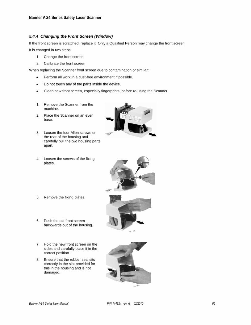
Banner AG4 Series Safety Laser Scanner
Banner AG4 Series User Manual P/N 144924 rev. A 02/2010 85
5.4.4 Changing the Front Screen (Window)
If the front screen is scratched, replace it. Only a Qualified Person may change the front screen.
It is changed in two steps:
1. Change the front screen
2. Calibrate the front screen
When replacing the Scanner front screen due to contamination or similar:
Perform all work in a dust-free environment if possible.
Do not touch any of the parts inside the device.
Clean new front screen, especially fingerprints, before re-using the Scanner.
1. Remove the Scanner from the machine.
2. Place the Scanner on an even base.
3. Loosen the four Allen screws on the rear of the housing and carefully pull the two housing parts apart.
4. Loosen the screws of the fixing plates.
5. Remove the fixing plates.
6. Push the old front screen backwards out of the housing.
7. Hold the new front screen on the sides and carefully place it in the correct position.
8. Ensure that the rubber seal sits correctly in the slot provided for this in the housing and is not damaged.
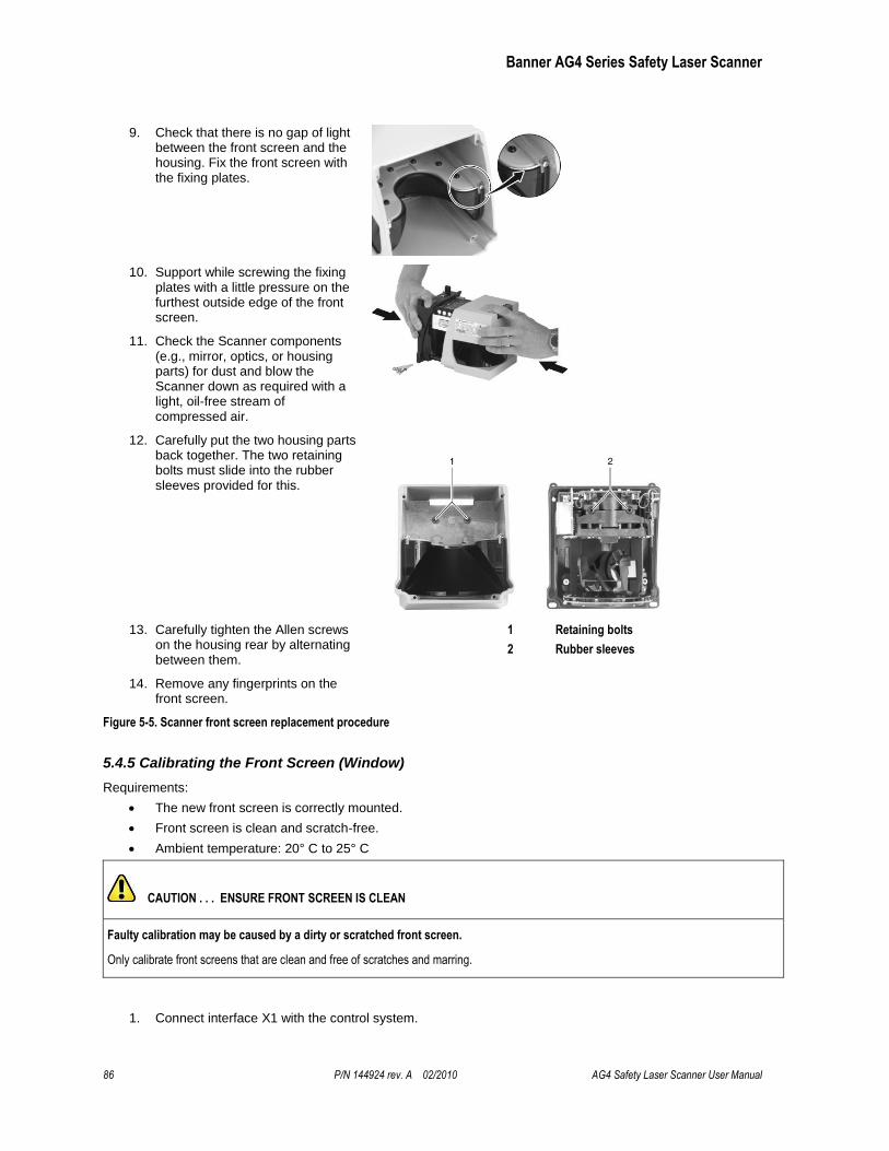
Banner AG4 Series Safety Laser Scanner
86 P/N 144924 rev. A 02/2010 AG4 Safety Laser Scanner User Manual
9. Check that there is no gap of light between the front screen and the housing. Fix the front screen with the fixing plates.
10. Support while screwing the fixing plates with a little pressure on the furthest outside edge of the front screen.
11. Check the Scanner components (e.g., mirror, optics, or housing parts) for dust and blow the Scanner down as required with a light, oil-free stream of compressed air.
12. Carefully put the two housing parts back together. The two retaining bolts must slide into the rubber sleeves provided for this.
13. Carefully tighten the Allen screws on the housing rear by alternating between them.
1 Retaining bolts
2 Rubber sleeves
14. Remove any fingerprints on the front screen.
Figure 5-5. Scanner front screen replacement procedure
5.4.5 Calibrating the Front Screen (Window)
Requirements:
The new front screen is correctly mounted.
Front screen is clean and scratch-free.
Ambient temperature: 20° C to 25° C
CAUTION . . . ENSURE FRONT SCREEN IS CLEAN
Faulty calibration may be caused by a dirty or scratched front screen.
Only calibrate front screens that are clean and free of scratches and marring.
1. Connect interface X1 with the control system.
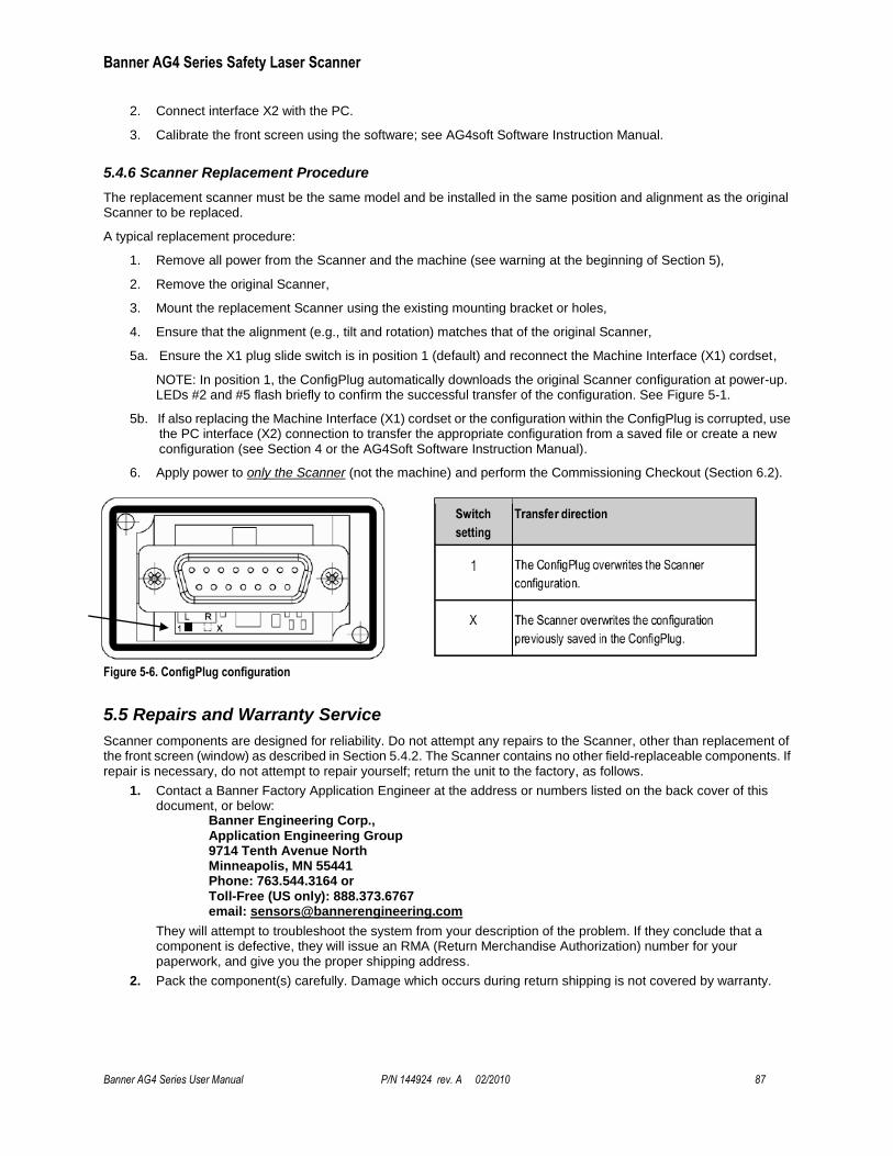
Banner AG4 Series Safety Laser Scanner
Banner AG4 Series User Manual P/N 144924 rev. A 02/2010 87
2. Connect interface X2 with the PC.
3. Calibrate the front screen using the software; see AG4soft Software Instruction Manual.
5.4.6 Scanner Replacement Procedure
The replacement scanner must be the same model and be installed in the same position and alignment as the original Scanner to be replaced.
A typical replacement procedure:
1. Remove all power from the Scanner and the machine (see warning at the beginning of Section 5),
2. Remove the original Scanner,
3. Mount the replacement Scanner using the existing mounting bracket or holes,
4. Ensure that the alignment (e.g., tilt and rotation) matches that of the original Scanner,
5a. Ensure the X1 plug slide switch is in position 1 (default) and reconnect the Machine Interface (X1) cordset,
NOTE: In position 1, the ConfigPlug automatically downloads the original Scanner configuration at power-up. LEDs #2 and #5 flash briefly to confirm the successful transfer of the configuration. See Figure 5-1.
5b. If also replacing the Machine Interface (X1) cordset or the configuration within the ConfigPlug is corrupted, use the PC interface (X2) connection to transfer the appropriate configuration from a saved file or create a new configuration (see Section 4 or the AG4Soft Software Instruction Manual).
6. Apply power to only the Scanner (not the machine) and perform the Commissioning Checkout (Section 6.2).
Figure 5-6. ConfigPlug configuration
5.5 Repairs and Warranty Service
Scanner components are designed for reliability. Do not attempt any repairs to the Scanner, other than replacement of the front screen (window) as described in Section 5.4.2. The Scanner contains no other field-replaceable components. If repair is necessary, do not attempt to repair yourself; return the unit to the factory, as follows.
1. Contact a Banner Factory Application Engineer at the address or numbers listed on the back cover of this document, or below:
Banner Engineering Corp., Application Engineering Group 9714 Tenth Avenue North Minneapolis, MN 55441 Phone: 763.544.3164 or Toll-Free (US only): 888.373.6767 email: [email protected]
They will attempt to troubleshoot the system from your description of the problem. If they conclude that a component is defective, they will issue an RMA (Return Merchandise Authorization) number for your paperwork, and give you the proper shipping address.
2. Pack the component(s) carefully. Damage which occurs during return shipping is not covered by warranty.
Banner AG4 Series Safety Laser Scanner
88 P/N 144924 rev. A 02/2010 AG4 Safety Laser Scanner User Manual
6. Safety System Testing Study each procedure in its entirety, to understand each step thoroughly before beginning. Refer all questions
to a Banner applications engineer, at the address or numbers listed on the back cover of this manual. Checkouts must be performed as detailed in Section 6.1 below and results must be recorded and kept in the appropriate place (e.g., near the machine, and/or in a technical file). This must include a printout of the Scanner’s configuration and the shape of all Protective Fields.
Additional factors and checks may be required that are dependent on the application, machine, or local regulations and laws. A user risk assessment will determine what these additional factors and checks will be and should be incorporated with the checkouts below. For easy reference, print out the procedures and post them near the machine/application.
6.1 Schedule of Checkouts
Trip Test: The procedure for Scanner trip test is described in Section 3.4.3. This procedure must be performed at
installation, and at any time the Scanner, the guarded machine, or any part of the application is installed or altered. The procedure must be performed by a Qualified Person.
Commissioning Checkout: Perform the procedure described in Section 6.2 at installation or whenever changes are
made to the Scanner configuration or to the machine being guarded. The procedure must be performed by a Qualified Person.
Shift/Daily Checkout: Perform the Daily Checkout procedure, described in Section 6.3, at each shift change or machine setup change, whenever the System is powered up — at least daily. The procedure may be performed by a
Designated Person or a Qualified Person.
Semi-Annual Checkout: Perform this procedure, described in Section 6.4, every six months following installation. The
procedure must be performed by a Qualified Person.
NOTE: The Shift/Daily and Semi-Annual Checkout procedures are also found on Banner document p/n 147899 (contained on the installation CD).
WARNING . . . PERIODIC CHECKOUTS
The commissioning, periodic and daily safety system checks must be performed by appropriate personnel at the appropriate times in order to
ensure that the safety system is operating as intended. Failure to perform these checks may create a potentially dangerous situation
which could lead to serious injury or death.

Banner AG4 Series Safety Laser Scanner
Banner AG4 Series User Manual P/N 144924 rev. A 02/2010 89
6.2 Commissioning Checkout
Perform this checkout procedure as part of the Scanner installation (after it has been interfaced to the guarded machine as described in Sections 3.5 and 3.7), or whenever changes are made to the system (either a new configuration of the Scanner or changes to the machine). Record checkout results and store on or near the guarded
machine as required by applicable standards.
Requirements:
• The AG4 has been configured with the configuration software.
• Interface X1 of the Scanner is connected to the control system or safety switching device.
• Protective housing (cap) is attached to interface X2 (PC connection optional).
Tester: Qualified Person (as defined in Section 4.1)
To prepare the System for this checkout:
1. Examine the guarded machine to verify that it is of a type and design compatible with the Scanner. See Section 1.11 for information on the proper use and intended purpose, including misapplications.
2. Verify that the Scanner is configured for the intended application (see Section 4.2 and 4.4) and all mounting hardware is secured.
3. Verify that the minimum safety (separation) distance from the closest hazard of the guarded machine to the Protective Field(s) is not less than the calculated distance, per Section 3.3.4 (U.S. stationary applications), 3.3.5 (European stationary applications), or 3.4.3 (mobile applications) of this manual.
4. Verify that:
Access to any dangerous parts of the guarded machine is not possible from any direction not protected by the Scanner, hard guarding, or supplemental safeguarding, and
It is not possible for a person to stand between or climb over/under the protected Field(s) and the dangerous parts of the machine, or stand on top of the Scanner (see Section 3), or
Supplemental safeguarding and hard guarding, as described by the appropriate safety standards, are in place and functioning properly in any space between the Protective Field(s) and any hazard which is large enough to allow a person to be undetected by the Scanner (see Sections 3.3.1 and 3.3.3).
5. Verify that all reset switches are mounted outside and in full view of the guarded area, out of reach of anyone inside the guarded area, and that means of preventing inadvertent use is in place (see Section 3.3.7).
6. Examine the electrical wiring connections between the Scanner OSSD outputs and the guarded machine’s control elements to verify that the wiring meets the requirements stated in Sections 3.5 and 3.7.
7. Remove all obstructions from the Protective Field(s). Apply power to the Scanner system. Verify that power to the guarded machine is OFF.
If the Scanner is configured for Start Interlock (Manual Power-Up), the Yellow Start/Restart (Reset)
indicator (LED #5) will be ON. Perform a manual reset (close the reset switch for 1/4 to 5 seconds, then open the switch) to turn ON the OSSD outputs.
If the Scanner is configured for Start Test (Test at power-up), the Yellow Start/Restart (Reset)
indicator (LED #5) will be ON. Perform the test by inserting an object equal to or greater than the configured resolution (e.g. test piece) momentarily into the Protective Field and then remove. Then, once the field is clear the OSSD outputs will turn ON.
If the Scanner is configured for Automatic Start (Automatic Reset), the two GREEN indicators (LED
#1 and LED #3 on Figure 3) and the OSSD outputs turn ON (after the restart delay time).
WARNING . . . UNPREDICTABLE MACHINE STARTUP
There is a risk of unpredictable machine behavior at the initial start up of the machine. The Qualified Person must take precautions
to ensure that no one is in or near the hazardous area during these safety system tests.
Banner AG4 Series Safety Laser Scanner
90 P/N 144924 rev. A 02/2010 AG4 Safety Laser Scanner User Manual
8. Observe the Status indicators and the Diagnostic Display:
Lockout: LED #5 flashes at a 4Hz rate (other LEDs may also be ON or flashing depending on the fault,
see Section 5 and Table 10).
Protective Field interrupted: LED #2 (Yellow) and LED #3 (Red) are ON
Protective Field Clear and OSSDs ON: LED #1 (Green) and LED #4 (Green) are ON
Start/Restart Interlock (OSSDs OFF, waiting for Reset): LED #1 (Green), LED #3 (Red), and LED #5
(Yellow) are ON.
9. An interrupted Protective Field (PF) condition indicates that one or more objects are being detected within the active protected Field. To correct this situation, identify the interruption via the AG4Soft ―Measured contour display‖ operating mode or by observing the area covered by the Protective Field, and then remove all objects or realign the Scanner per Section 3. If the system is in a Start/Restart Interlock (waiting for Reset) condition, perform a manual reset.
10. Once the two Green LED indicators are ON, perform the trip test (described in Section 3.4.3) on each of the
configured Protective Fields to verify proper system operation and to detect possible unmonitored areas. Verify that if the Protective Field boundary is identified (i.e., marked on the floor), that it matches the corresponding Protective Field. Do not continue until the Scanner System passes the trip test. Do not expose any individual to any hazard during the following checks.
11. Apply power to the guarded machine and verify that the machine does not start up. Interrupt the Protective Field with the appropriate test piece (whose size matches the configured resolution) and verify that it is not possible for the guarded machine to be put into motion while the Protective Field is interrupted. Repeat for each configured Protective Field.
12. Initiate the machine cycle or motion of the guarded machine or mobile vehicle. While it is moving, use the appropriate test piece to interrupt the Protective Field. Do not attempt to insert the test piece into the dangerous parts of the machine or directly in the path of the moving vehicle. Upon interrupting the
Protective Field (at any point), verify that:
For stationary applications: The dangerous parts of the machine come to a stop with no apparent delay. Remove the test piece from the Protective Field; verify that the machine does not automatically restart, and that the initiation device(s) must be engaged to restart the machine.
For mobile applications: The vehicle stops within the identified/predetermined distance. Remove the test piece from the Protective Field; verify that the vehicle does not unintentionally restart, and, if required, that the initiation device(s) must be engaged to restart the mobile vehicle. This must be accomplished at numerous points along the entire route (i.e., testing each of the Field Pairs in the
configuration).
13. Remove electrical power to the Scanner. Verify that both OSSD outputs immediately turn OFF and the machine is not capable of starting until power is re-applied to the Scanner.
14. Test the machine stopping response time, using an instrument designed for that purpose, to verify that it is the same or less than the overall system response time specified by the machine manufacturer. (A Banner Applications Engineer can recommend a suitable instrument.)
WARNING . . . BEFORE APPLYING POWER TO THE MACHINE
Verify that the guarded area is clear of personnel and unwanted materials (such as tools) before applying power to the guarded machine. Failure to
do so could result in serious bodily injury or death.
WARNING . . . IF TRIP TEST INDICATES A PROBLEM
If the Scanner does not respond properly to the trip test, do not attempt to use the system. If this occurs, the Scanner cannot be relied on to stop
dangerous machine motion when a person or object enters the Protective Field. Serious bodily injury or death could result.
Banner AG4 Series Safety Laser Scanner
Banner AG4 Series User Manual P/N 144924 rev. A 02/2010 91
15. If the PC Interface (X2) cordset is to be removed, ensure that the supplied X2 connector dust plug (AG4-PCD9)
is re-installed.
Do not continue operation until the entire checkout procedure is complete and all problems are corrected.
6.3 Shift/Daily Checkout
Perform the Daily Checkout procedure at every shift change, power-up and machine set-up change – and at intervals not to exceed 24 hours during continuous machine run periods. Record a copy of the checkout results
and store in the appropriate place (e.g., near or on the machine, in the machine’s technical file).
Tester: Designated Person or Qualified Person (as described in Section 4.1).
Refer to the procedure contained on the Daily Checkout card (Banner p/n 147899) contained on the software disc included with the Scanner. If the checkout card is missing, contact Banner Engineering or download at www.bannerengineering.com. Print out the instructions to be posted near the installation/guarded machine, for easy reference.
6.4 Semi-Annual (Six-Month) Checkout
Perform the Semi-Annual Checkout procedure every six months following system installation, or whenever changes are made to the Scanner configuration or to the machine. A copy of checkout results should be recorded
and kept in the appropriate place (e.g., near or on the machine, in the machine’s technical file).
Tester: Qualified Person (as described in Section 4.1).
Refer to the procedure contained on the Semi-Annual Checkout card (Banner p/n 147899) contained on the software disc included with the Scanner. If the checkout card is missing, contact Banner Engineering or download at www.bannerengineering.com. Print out the instructions to be posted near the installation/guarded machine, for easy reference.
WARNING . . . DO NOT USE MACHINE UNTIL SYSTEM IS WORKING PROPERLY
If all of these checks cannot be verified, do not attempt to use or operate the machine until the defect or problem has been
corrected. Attempts to use the guarded machine under such conditions could result in serious bodily injury or death.
Banner AG4 Series Safety Laser Scanner
92 P/N 144924 rev. A 02/2010 AG4 Safety Laser Scanner User Manual
7. Glossary
7.1 List of Abbreviations
CE European Conformity mark
DZ Danger Zone
EDM External Device Monitoring
FSD Final Switching Device
IEC International Electrotechnical Commission
IP... Ingress Protection
ISO International Organization for Standardization
LED Light Emitting Diode
OSSD Output Signal Switching Device
MPCE Machine Primary Control Element
PF Protective Field
PLC Programmable Logic Controller
VDC Voltage Direct Current
WF Warning Field
7.2 List of Terms
The following terms are used frequently in this manual. Where possible, this manual uses definitions from the international product performance
standards that govern the design of the AG4. For more definitions, visit
http://www.bannerengineering.com/training/glossary.php.
CE – European Conformity. The CE mark on a product or machine establishes its compliance with all relevant European Union (EU) Directives and
the associated safety standards.
Danger Zone – Defined as the danger area for equipment in operation where there is a serious risk of injury or death to personnel.
Designated Person – A person or persons identified and designated in writing, by the employer, as being appropriately trained and qualified to
perform a specified checkout procedure.
External Device Monitoring – This feature allows the System to monitor the status of external devices, such as MPCEs.
Fixed Guarding – Screens, bars, or other mechanical barriers that prevent a person from entering or remaining in the danger zone undetected.
Key Reset – A key-operated switch used to restore the FSDs and SSD to the ON state from a lockout condition. Also refers to the act of using the
switch to Reset the System.
Latch Condition – The response of the OSSD outputs (they turn OFF) when an object blocks/interrupts a light beam of the System operating in
Latch mode. A manual Reset must be performed after all objects are removed (beam(s) clear) to Reset the output latch and allow the outputs to
turn ON.
Lockout Condition – A condition of the System that is automatically attained when it detects internal or certain external errors. A lockout condition
causes all of the System OSSD outputs to turn or remain OFF, sending a stop signal to the guarded machine. To restore the System to Run mode,
all errors must be corrected and a manual Reset must be performed.
Machine Primary Control Element (MPCE) – An electrically powered element, external to the System which directly controls the machine’s
normal operating motion in such a way that it is last (in time) to operate when motion is either initiated or arrested.
Machine Response Time – The time between the interruption by the System OSSDs and the instant when the dangerous parts of the machine
reach a safe state by being brought to rest.
Separation (Safety) Distance – That distance, along the direction of approach, between the outermost position at which the appropriate test
piece is just detected and the nearest dangerous machine part(s). Also called Safety distance.
Start/restart (interlock) – When applied to the function of a safety or safeguarding device, this term refers to the ability of the device to prevent or
allow the machine operating cycle to begin or resume by normal actuating means after the cause of a stop has been removed. Also called reset.
NOTE: The reset (clearing of the Start/Restart interlock) of the device must not cause hazardous motion or a hazardous situation, but only enable
the normal start command.
Banner AG4 Series Safety Laser Scanner
Banner AG4 Series User Manual P/N 144924 rev. A 02/2010 93
Protective Field – The Scanner effective Separation (safety) distance/Safety distance that is required to stop the machine before a person who
enters the Protective Field reaches the machine and is specified in ISO 13855 and associated standards.
Response Time – The time between the interruption by the System OSSDs and the instant when the dangerous parts of the machine reach a safe
state by being brought to rest.
Qualified Person – A person or persons who, by possession of a recognized degree or certificate of professional training, or who, by extensive
knowledge, training, and experience, has successfully demonstrated the ability to solve problems relating to the subject matter and work.
Response Time – The time between the physical initiation of the safety device and the machine coming to a stop or the risk being removed.
Trip Condition – In trip output models, the response of the FSD relays when an object equal to or greater than the diameter of the specified test
piece enters the Protective Field. In a trip condition, FSD 1 and FSD 2 simultaneously de-energize and open their contacts. A trip condition clears
automatically when the object is removed from the Protective Field.
User – An entity that utilizes a machine or related equipment. The user is typically regarded as the entity that employs the operator of the machine
and/or supervises the operation of the machine, including production and maintenance.

Banner AG4 Series Safety Laser Scanner
94 P/N 144924 rev. A 02/2010 AG4 Safety Laser Scanner User Manual
EC Declaration of Conformity
Banner Engineering Corp.
9714 Tenth Avenue North
Minneapolis, MN 55441-5019 USA
We herewith declare that the Banner AG4 Series Safety Laser Scanner for industrial control is in conformity with the provisions of the Machinery Directive (Directive 98/37/EC Machinery Directive [valid until 29 December 2009] and 2006/42/EC Machinery Directive), and all essential Health and Safety Requirements have been met.
3/17/2010 3/17/2010
R. Eagle / Engineering Manager Date Peter Mertens / Managing Director Date
Banner Engineering Corp. Banner Engineering Europe
9714 Tenth Avenue North Park Lane, Culliganlaan 2F
Minneapolis, MN 55441-5019 USA 1831 Diegem, Belgium
Download the complete EC Declaration of Conformity as a PDF file at www.bannerengineering.com/AreaScanner

Banner AG4 Series Safety Laser Scanner
Banner AG4 Series User Manual P/N 144924 rev. A 02/2010 95

Banner AG4 Series Safety Laser Scanner
96 P/N 144924 rev. A 02/2010 AG4 Safety Laser Scanner User Manual