Embed Size (px)
Citation preview
Magnetic Base
Plumb Bob
Cross Line of Wheels
A
B
C
D
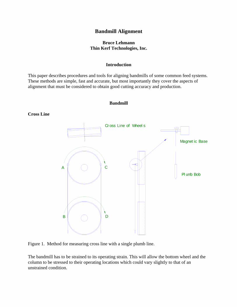
Figure 1. Method for measuring cross line with a single plumb line.
Bandmill Alignment
Bruce LehmannThin Kerf Technologies, Inc.
Introduction
This paper describes procedures and tools for aligning bandmills of some common feed systems. These methods are simple, fast and accurate, but most importantly they cover the aspects ofalignment that must be considered to obtain good cutting accuracy and production.
Bandmill
Cross Line
The bandmill has to be strained to its operating strain. This will allow the bottom wheel and thecolumn to be stressed to their operating locations which could vary slightly to that of anunstrained condition.
Setting up and using the Plumb Line
The method described here for measuring crossline is slightly different that usual method ofhanging two plumb lines over pieces of key-stock. However, it is faster and inherently moreaccurate.
1. Clean the rim of the top wheel at Point A, and the bottom wheel at Point B, as shown in thediagram below. Attach a magnetic base to the top wheel at Point A.
2. Attach the plumb bob to the magnetic base so that the line hangs over the clamp. To steadythe plumb line, the plumb bob can hang in a can of oil, or let the point drag through somesawdust you hold in your hand.
3. Measure and record the gap between the line and the wheel rim at Point B. 4. Rotate the wheels until the magnetic base is at Point C. Ensure that the line is still hanging
over the clamp. Point D, on the bottom wheel, will be the same clean point on the bottomwheel. By taking the measurements this way, any error due to runout of the wheel rim iseliminated.
5. Measure the gap at Point D and compare it with the previous reading.6. Adjust the top wheel as necessary.7. Recheck the measurements.8. As a final check, remove the plumb lines and run the machine for a few minutes, then stop
and lock out the machine.9. Measure the distance from the edge of the blade to the wheel rim.10. By hand, rotate the wheel backwards for one complete revolution of the band.11. Again, measure the distance from the edge of the blade to the wheel rim. If the distance is
different from the first measurement, then there is still crossline.
Axial Alignment of Wheels and Guides
It is important that the rims of the wheels on the side where the teeth overhang the wheels are inline with each other. In other words you want the blade to overhang the same amount on the topand bottom wheels. If the overhang on one wheel is too large, but minimal on the other wheel,then the front edge of the blade will curl inward and change the attack angle of the teeth.Sometimes the top wheel needs to be moved axially (parallel to the shaft) to make the overhangsequal.
Even more important is to position the guides so they fully support the saw. If the bladeoverhangs the guides by more than 3/8 inch, then the blade will curl inward.
Guide Pressure
Having the correct amount of guide pressure is important. Too much pressure on the guides willwear quickly, resulting in a change in the position of the saw. Also, because the front edge of theguides wears the most, the blade will curl slightly so that the teeth are not presented squarely tothe feed. If there is too little guide pressure the saw stiffness is reduced.
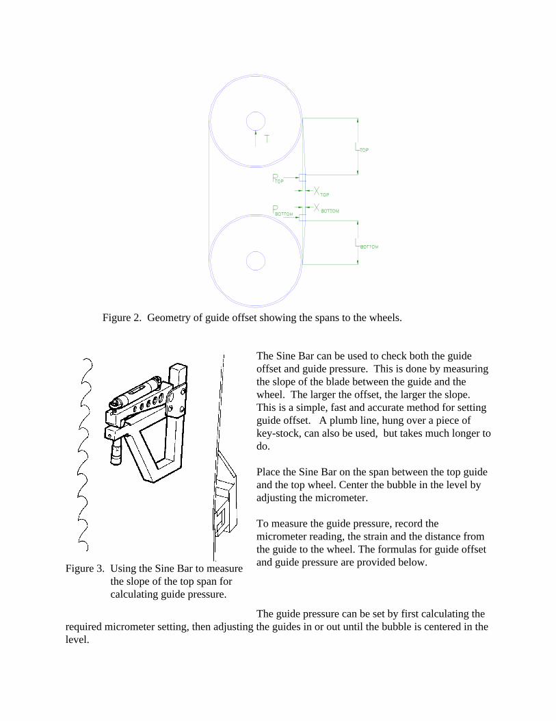
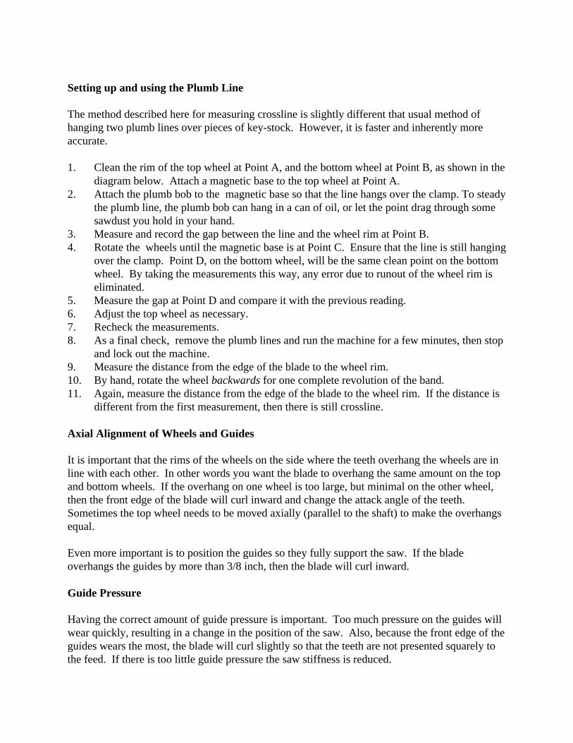
Figure 2. Geometry of guide offset showing the spans to the wheels.
Figure 3. Using the Sine Bar to measurethe slope of the top span forcalculating guide pressure.
The Sine Bar can be used to check both the guideoffset and guide pressure. This is done by measuringthe slope of the blade between the guide and thewheel. The larger the offset, the larger the slope. This is a simple, fast and accurate method for settingguide offset. A plumb line, hung over a piece ofkey-stock, can also be used, but takes much longer todo.
Place the Sine Bar on the span between the top guideand the top wheel. Center the bubble in the level byadjusting the micrometer.
To measure the guide pressure, record themicrometer reading, the strain and the distance fromthe guide to the wheel. The formulas for guide offsetand guide pressure are provided below.
The guide pressure can be set by first calculating therequired micrometer setting, then adjusting the guides in or out until the bubble is centered in thelevel.
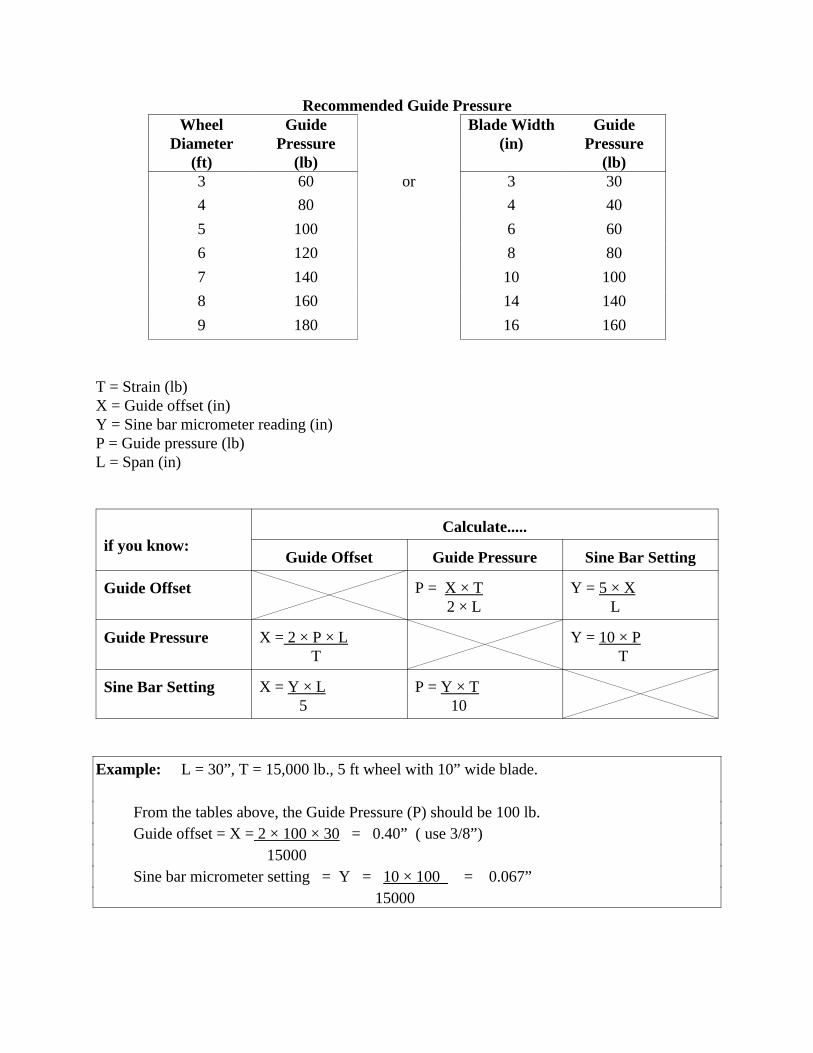
Recommended Guide PressureWheel
Diameter(ft)
GuidePressure
(lb)
Blade Width(in)
GuidePressure
(lb)3 60 or 3 30
4 80 4 40
5 100 6 60
6 120 8 80
7 140 10 100
8 160 14 140
9 180 16 160
T = Strain (lb)X = Guide offset (in)Y = Sine bar micrometer reading (in)P = Guide pressure (lb)L = Span (in)
if you know:Calculate.....
Guide Offset Guide Pressure Sine Bar Setting
Guide Offset P = X × T 2 × L
Y = 5 × X L
Guide Pressure X = 2 × P × L T
Y = 10 × P T
Sine Bar Setting X = Y × L 5
P = Y × T 10
Example: L = 30”, T = 15,000 lb., 5 ft wheel with 10” wide blade.
From the tables above, the Guide Pressure (P) should be 100 lb.Guide offset = X = 2 × 100 × 30 = 0.40” ( use 3/8”)
15000Sine bar micrometer setting = Y = 10 × 100 = 0.067”
15000
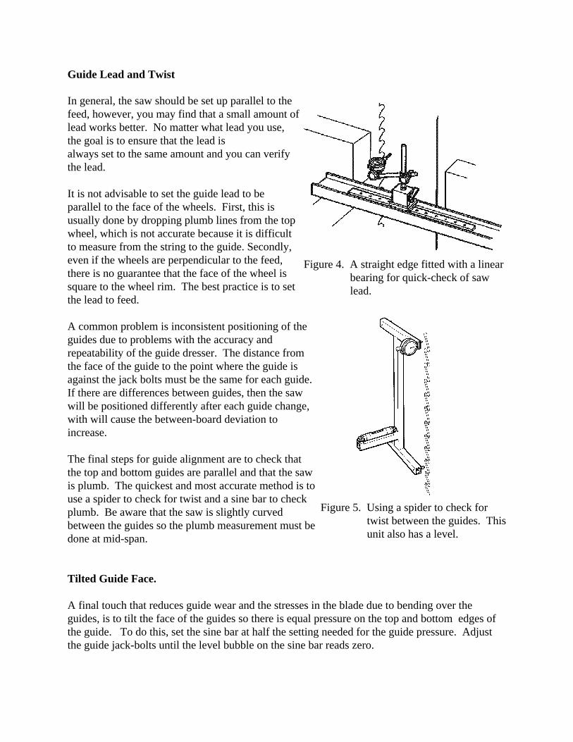
Figure 4. A straight edge fitted with a linearbearing for quick-check of sawlead.
Figure 5. Using a spider to check fortwist between the guides. Thisunit also has a level.
Guide Lead and Twist
In general, the saw should be set up parallel to thefeed, however, you may find that a small amount oflead works better. No matter what lead you use,the goal is to ensure that the lead isalways set to the same amount and you can verifythe lead.
It is not advisable to set the guide lead to beparallel to the face of the wheels. First, this isusually done by dropping plumb lines from the topwheel, which is not accurate because it is difficultto measure from the string to the guide. Secondly,even if the wheels are perpendicular to the feed,there is no guarantee that the face of the wheel issquare to the wheel rim. The best practice is to setthe lead to feed.
A common problem is inconsistent positioning of theguides due to problems with the accuracy andrepeatability of the guide dresser. The distance fromthe face of the guide to the point where the guide isagainst the jack bolts must be the same for each guide. If there are differences between guides, then the sawwill be positioned differently after each guide change,with will cause the between-board deviation toincrease.
The final steps for guide alignment are to check thatthe top and bottom guides are parallel and that the sawis plumb. The quickest and most accurate method is touse a spider to check for twist and a sine bar to checkplumb. Be aware that the saw is slightly curvedbetween the guides so the plumb measurement must bedone at mid-span.
Tilted Guide Face.
A final touch that reduces guide wear and the stresses in the blade due to bending over theguides, is to tilt the face of the guides so there is equal pressure on the top and bottom edges ofthe guide. To do this, set the sine bar at half the setting needed for the guide pressure. Adjustthe guide jack-bolts until the level bubble on the sine bar reads zero.
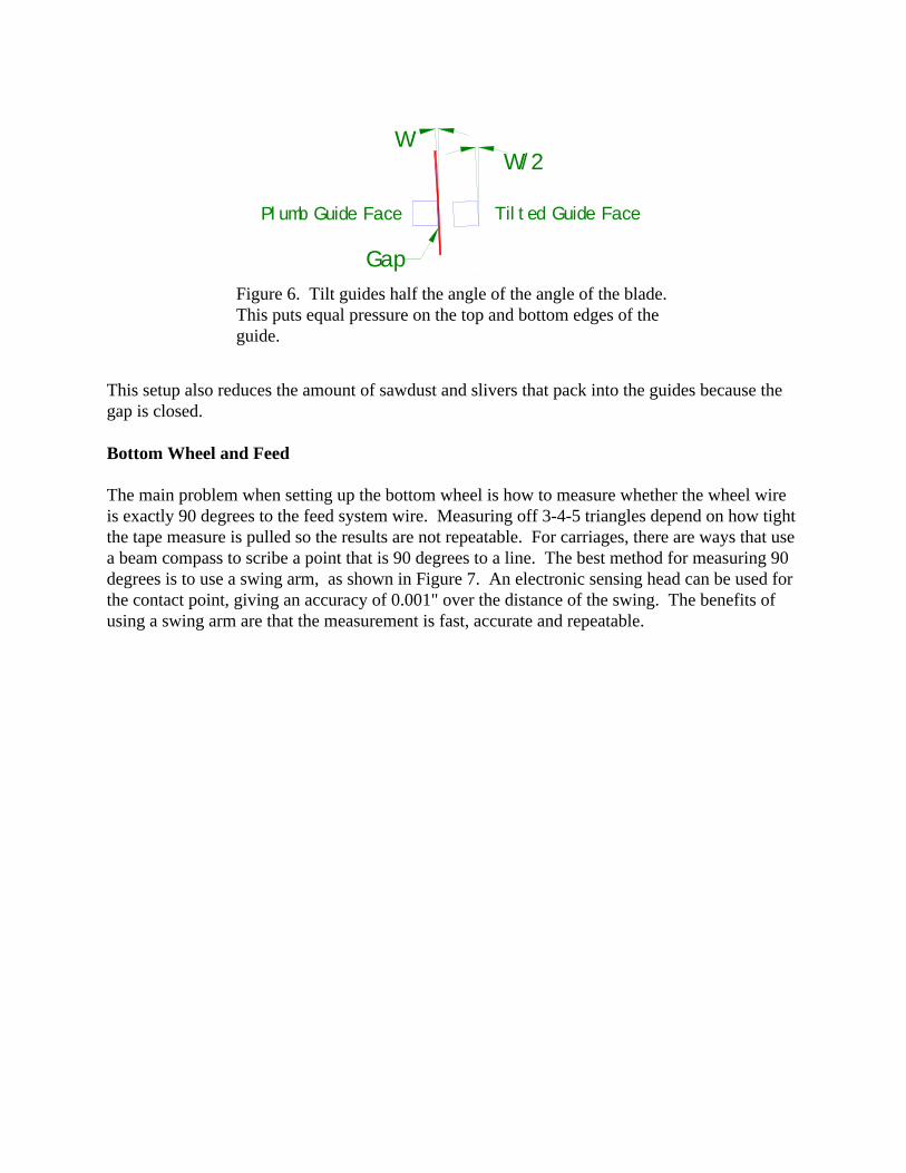
WW/2
Tilted Guide FacePlumb Guide Face
Gap
Figure 6. Tilt guides half the angle of the angle of the blade. This puts equal pressure on the top and bottom edges of theguide.
This setup also reduces the amount of sawdust and slivers that pack into the guides because thegap is closed.
Bottom Wheel and Feed
The main problem when setting up the bottom wheel is how to measure whether the wheel wireis exactly 90 degrees to the feed system wire. Measuring off 3-4-5 triangles depend on how tightthe tape measure is pulled so the results are not repeatable. For carriages, there are ways that usea beam compass to scribe a point that is 90 degrees to a line. The best method for measuring 90degrees is to use a swing arm, as shown in Figure 7. An electronic sensing head can be used forthe contact point, giving an accuracy of 0.001" over the distance of the swing. The benefits ofusing a swing arm are that the measurement is fast, accurate and repeatable.
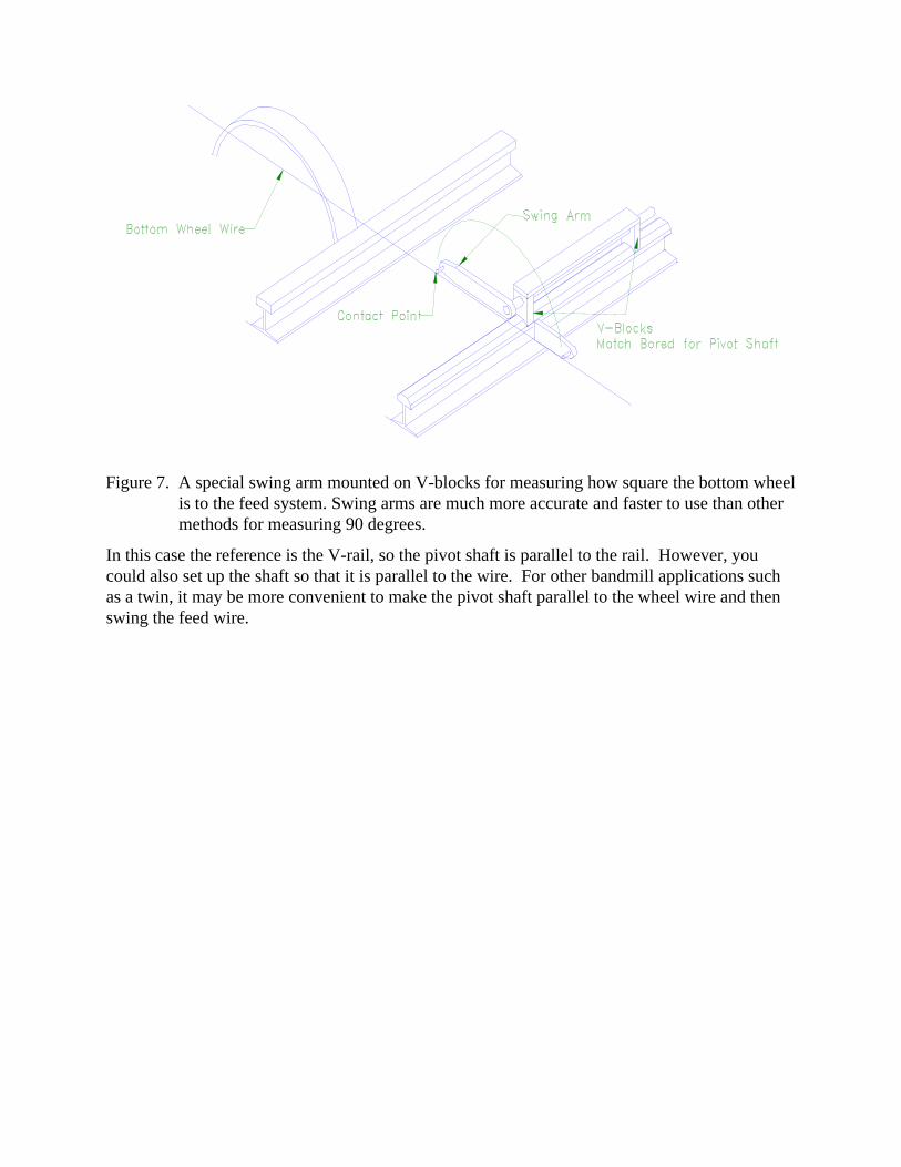
Figure 7. A special swing arm mounted on V-blocks for measuring how square the bottom wheelis to the feed system. Swing arms are much more accurate and faster to use than othermethods for measuring 90 degrees.
In this case the reference is the V-rail, so the pivot shaft is parallel to the rail. However, youcould also set up the shaft so that it is parallel to the wire. For other bandmill applications suchas a twin, it may be more convenient to make the pivot shaft parallel to the wheel wire and thenswing the feed wire.
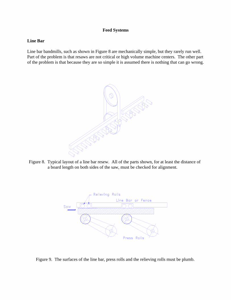
Figure 8. Typical layout of a line bar resew. All of the parts shown, for at least the distance ofa board length on both sides of the saw, must be checked for alignment.
Figure 9. The surfaces of the line bar, press rolls and the relieving rolls must be plumb.
Feed Systems
Line Bar
Line bar bandmills, such as shown in Figure 8 are mechanically simple, but they rarely run well. Part of the problem is that resaws are not critical or high volume machine centers. The other partof the problem is that because they are so simple it is assumed there is nothing that can go wrong.
Line BarPress Roll
Bed Roll
Wood
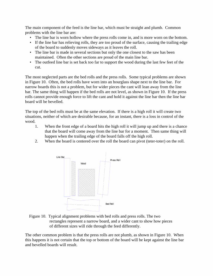
Figure 10. Typical alignment problems with bed rolls and press rolls. The tworectangles represent a narrow board, and a wider cant to show how piecesof different sizes will ride through the feed differently.
The main component of the feed is the line bar, which must be straight and plumb. Commonproblems with the line bar are:
• The line bar is worn hollow where the press rolls come in, and is more worn on the bottom.• If the line bar has relieving rolls, they are too proud of the surface, causing the trailing edge
of the board to suddenly moves sideways as it leaves the roll.• The line bar is made in several sections but only the one closest to the saw has been
maintained. Often the other sections are proud of the main line bar.• The outfeed line bar is set back too far to support the wood during the last few feet of the
cut.
The most neglected parts are the bed rolls and the press rolls. Some typical problems are shownin Figure 10. Often, the bed rolls have worn into an hourglass shape next to the line bar. Fornarrow boards this is not a problem, but for wider pieces the cant will lean away from the linebar. The same thing will happen if the bed rolls are not level, as shown in Figure 10. If the pressrolls cannot provide enough force to lift the cant and hold it against the line bar then the line barboard will be bevelled.
The top of the bed rolls must be at the same elevation. If there is a high roll it will create twosituations, neither of which are desirable because, for an instant, there is a loss in control of thewood.
1. When the front edge of a board hits the high roll it will jump up and there is a chancethat the board will come away from the line bar for a moment. Then same thing willhappen when the trailing edge of the board falls off the high roll.
2. When the board is centered over the roll the board can pivot (teter-toter) on the roll.
The other common problem is that the press rolls are not plumb, as shown in Figure 10. Whenthis happens it is not certain that the top or bottom of the board will be kept against the line barand bevelled boards will result.
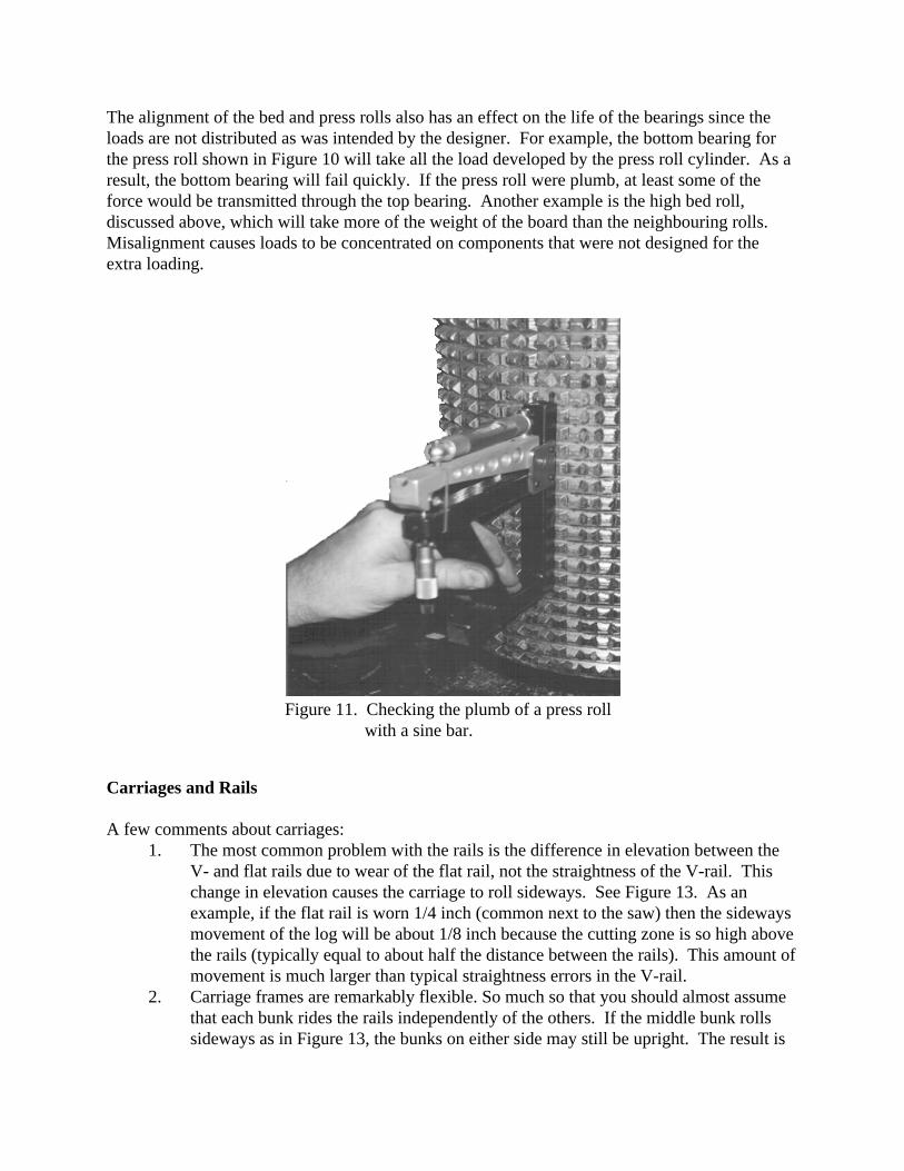
Figure 11. Checking the plumb of a press rollwith a sine bar.
The alignment of the bed and press rolls also has an effect on the life of the bearings since theloads are not distributed as was intended by the designer. For example, the bottom bearing forthe press roll shown in Figure 10 will take all the load developed by the press roll cylinder. As aresult, the bottom bearing will fail quickly. If the press roll were plumb, at least some of theforce would be transmitted through the top bearing. Another example is the high bed roll,discussed above, which will take more of the weight of the board than the neighbouring rolls. Misalignment causes loads to be concentrated on components that were not designed for theextra loading.
Carriages and Rails
A few comments about carriages:1. The most common problem with the rails is the difference in elevation between the
V- and flat rails due to wear of the flat rail, not the straightness of the V-rail. Thischange in elevation causes the carriage to roll sideways. See Figure 13. As anexample, if the flat rail is worn 1/4 inch (common next to the saw) then the sidewaysmovement of the log will be about 1/8 inch because the cutting zone is so high abovethe rails (typically equal to about half the distance between the rails). This amount ofmovement is much larger than typical straightness errors in the V-rail.
2. Carriage frames are remarkably flexible. So much so that you should almost assumethat each bunk rides the rails independently of the others. If the middle bunk rollssideways as in Figure 13, the bunks on either side may still be upright. The result is
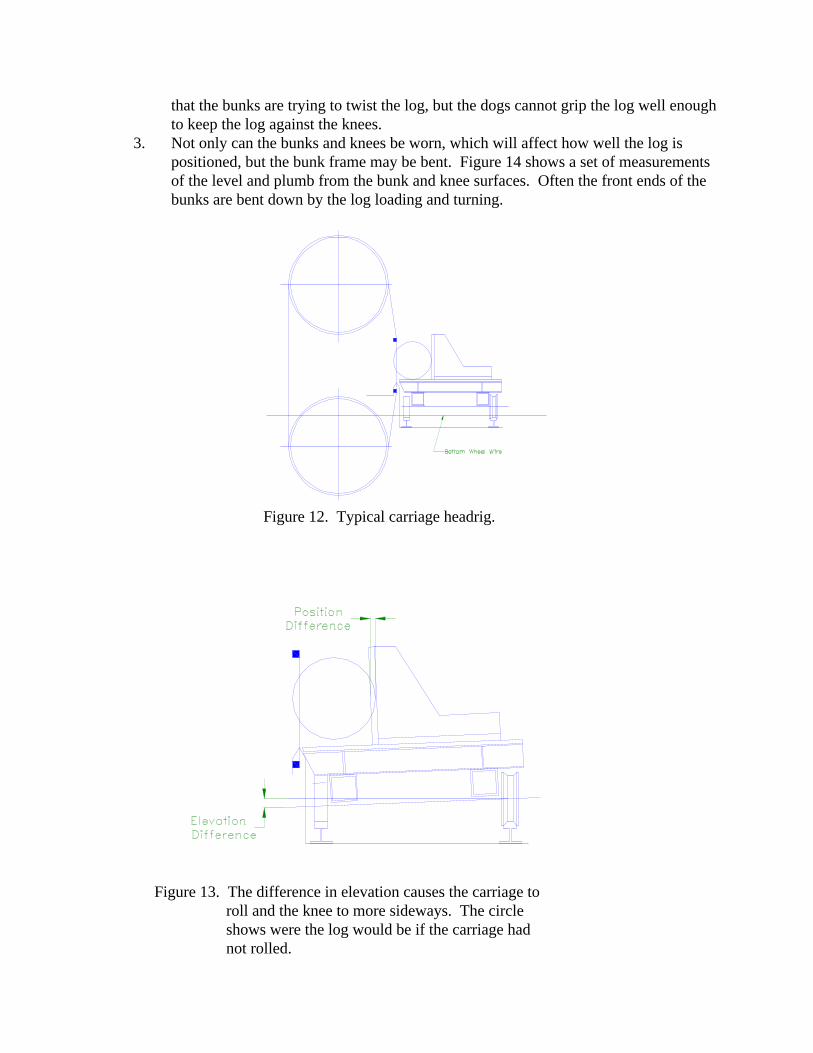
Figure 12. Typical carriage headrig.
Figure 13. The difference in elevation causes the carriage toroll and the knee to more sideways. The circleshows were the log would be if the carriage hadnot rolled.
that the bunks are trying to twist the log, but the dogs cannot grip the log well enoughto keep the log against the knees.
3. Not only can the bunks and knees be worn, which will affect how well the log ispositioned, but the bunk frame may be bent. Figure 14 shows a set of measurementsof the level and plumb from the bunk and knee surfaces. Often the front ends of thebunks are bent down by the log loading and turning.
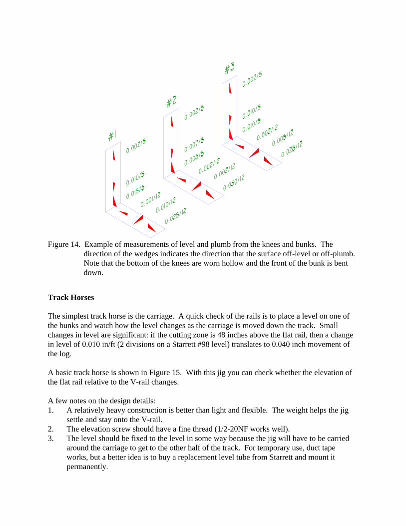
Figure 14. Example of measurements of level and plumb from the knees and bunks. Thedirection of the wedges indicates the direction that the surface off-level or off-plumb. Note that the bottom of the knees are worn hollow and the front of the bunk is bentdown.
Track Horses
The simplest track horse is the carriage. A quick check of the rails is to place a level on one ofthe bunks and watch how the level changes as the carriage is moved down the track. Smallchanges in level are significant: if the cutting zone is 48 inches above the flat rail, then a changein level of 0.010 in/ft (2 divisions on a Starrett #98 level) translates to 0.040 inch movement ofthe log.
A basic track horse is shown in Figure 15. With this jig you can check whether the elevation ofthe flat rail relative to the V-rail changes.
A few notes on the design details:1. A relatively heavy construction is better than light and flexible. The weight helps the jig
settle and stay onto the V-rail.2. The elevation screw should have a fine thread (1/2-20NF works well).3. The level should be fixed to the level in some way because the jig will have to be carried
around the carriage to get to the other half of the track. For temporary use, duct tapeworks, but a better idea is to buy a replacement level tube from Starrett and mount itpermanently.
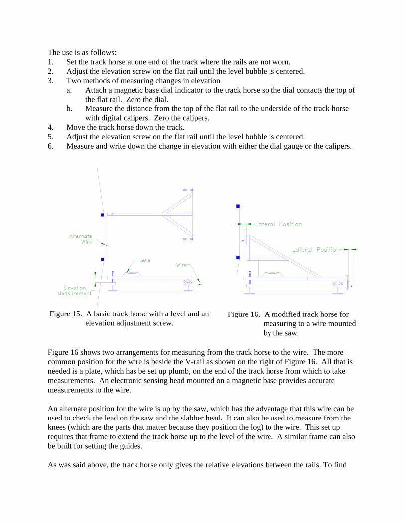
Figure 15. A basic track horse with a level and anelevation adjustment screw.
Figure 16. A modified track horse formeasuring to a wire mountedby the saw.
The use is as follows:1. Set the track horse at one end of the track where the rails are not worn.2. Adjust the elevation screw on the flat rail until the level bubble is centered. 3. Two methods of measuring changes in elevation
a. Attach a magnetic base dial indicator to the track horse so the dial contacts the top ofthe flat rail. Zero the dial.
b. Measure the distance from the top of the flat rail to the underside of the track horsewith digital calipers. Zero the calipers.
4. Move the track horse down the track.5. Adjust the elevation screw on the flat rail until the level bubble is centered. 6. Measure and write down the change in elevation with either the dial gauge or the calipers.
Figure 16 shows two arrangements for measuring from the track horse to the wire. The morecommon position for the wire is beside the V-rail as shown on the right of Figure 16. All that isneeded is a plate, which has be set up plumb, on the end of the track horse from which to takemeasurements. An electronic sensing head mounted on a magnetic base provides accuratemeasurements to the wire.
An alternate position for the wire is up by the saw, which has the advantage that this wire can beused to check the lead on the saw and the slabber head. It can also be used to measure from theknees (which are the parts that matter because they position the log) to the wire. This set uprequires that frame to extend the track horse up to the level of the wire. A similar frame can alsobe built for setting the guides.
As was said above, the track horse only gives the relative elevations between the rails. To find
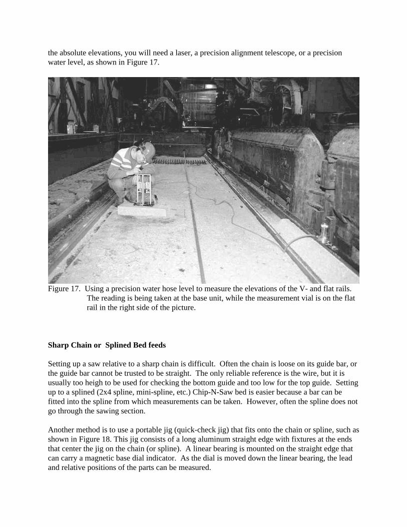
Figure 17. Using a precision water hose level to measure the elevations of the V- and flat rails.The reading is being taken at the base unit, while the measurement vial is on the flatrail in the right side of the picture.
the absolute elevations, you will need a laser, a precision alignment telescope, or a precisionwater level, as shown in Figure 17.
Sharp Chain or Splined Bed feeds
Setting up a saw relative to a sharp chain is difficult. Often the chain is loose on its guide bar, orthe guide bar cannot be trusted to be straight. The only reliable reference is the wire, but it isusually too heigh to be used for checking the bottom guide and too low for the top guide. Settingup to a splined (2x4 spline, mini-spline, etc.) Chip-N-Saw bed is easier because a bar can befitted into the spline from which measurements can be taken. However, often the spline does notgo through the sawing section.
Another method is to use a portable jig (quick-check jig) that fits onto the chain or spline, such asshown in Figure 18. This jig consists of a long aluminum straight edge with fixtures at the endsthat center the jig on the chain (or spline). A linear bearing is mounted on the straight edge thatcan carry a magnetic base dial indicator. As the dial is moved down the linear bearing, the leadand relative positions of the parts can be measured.
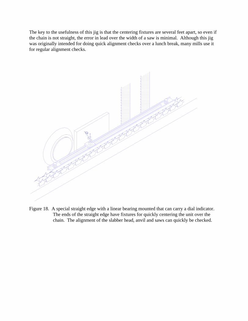
Figure 18. A special straight edge with a linear bearing mounted that can carry a dial indicator. The ends of the straight edge have fixtures for quickly centering the unit over thechain. The alignment of the slabber head, anvil and saws can quickly be checked.
The key to the usefulness of this jig is that the centering fixtures are several feet apart, so even ifthe chain is not straight, the error in lead over the width of a saw is minimal. Although this jigwas originally intended for doing quick alignment checks over a lunch break, many mills use itfor regular alignment checks.