Embed Size (px)
Citation preview
OPTIMISATION OF KERF QUALITY DURING PULSED Nd:YAG LASER CUTTING OF ALUMINIUM ALLOY SHEET
M.Tech. Chaki S.1, Prof. M.E. Ghosal S. PhD.2, M.Sc. Bathe R N. PhD3
Automobile Engineering Department-MCKV Institute of Engineering, West Bengal, India1 Mechanical Engineering Department– Jadavpur University, West Bengal, India2
Centre for Laser Processing of Materials-International Advance Research Centre for Power Metallurgy and New Materials, India3
Abstract: In pulsed Nd:YAG laser beam cutting, best cut quality can obtained by uniform kerf with minimum kerf width. Uniform kerf can be obtained on minimizing kerf unevenness or kerf deviation along length of cut for laser cutting. Till date, only a few experimental studies have been conducted on kerf deviation, in general. Present work has accomplished, pulsed Nd:YAG laser beam cutting of aluminum alloy sheet based on L9 orthogonal array and subsequent multi-objective optimization of two kerf qualities such as kerf width and kerf deviation using Taguchi quality loss function. A considerable improvement in kerf quality has been achieved with optimized parameter setting.
Keywords: Nd:YAG LASER BEAM CUTTING, ALUMINIUM ALLOY, KERF WIDTH, KERF DEVIATION, TAGUCHI METHOD.
1. Introduction Aluminum alloys are widely used in the aeronautics industry
and automotive industry as well because of their inherently low density, corrosion resistance, easiness of forming and recyclability. But due to highly reflective and heat sensitive (thermally conductive) in nature, aluminium poses difficulty during laser cutting. In laser cutting, thermal energy of highly focused laser beam is used for melting the sheet metal and molten material is driven out with the blow of a sufficiently strong coaxial gas jet to complete the cut along the desired contour1. In recent past, pulsed Nd:YAG laser cutting has been widely used for precision cutting of thin sheets of materials like mild steel2, stainless steel2,3, nickel-based super alloys4,5, Al/Li/SiC Metal Matrix Composites6 etc. But a very few efforts has been observed on laser cutting of aluminium alloy sheet. An experimental study on laser cutting of 2024 aluminium alloy sheet has been conducted by Araujo et al.7 without using any design of experiments and have analysed the microstructure in HAZ. Dubey and Yadava8 has anlaysed kerf quality during pulsed Nd:YAG laser beam cutting of Hindalco (India) made cold rolled 8011 aluminium alloy sheet of 0.9 mm thickness using Taguchi method. Recently cut quality for the aluminum alloy AA5083 have also investigated by Stournaras et al9 with a pulsed CO2 laser cutting system. However, it is observed that most of the experimental work2,3,4,5 on laser cutting have studied kerf quality based on kerf width and kerf taper (deviation along depth of cut) only, while minimization of them ensures a narrow kerf. But minimization of kerf unevenness or kerf deviation along length of cut is also an important quality characteristic for obtaining a uniform kerf. Authors have found only one paper8 where kerf deviation parameter has been taken care off.
In the present paper, pulsed Nd:YAG laser cutting of Hindalco (India) made cold rolled AA1200 aluminium alloy sheet of thickness 1.22 mm has been used for minimization of the kerf deviation while minimum kerf width is maintained at the same time. A multi-objective optimization technique using Taguchi quality loss function has been incorporated for the purpose.
2. Taguchi Method for optimisation Classical experimental design methods are time consuming
and require more experiments to be performed when the number of control factors is high. Taguchi methods10 use a special design of orthogonal arrays to study the entire factor space with only a small number of experiments. In the Taguchi method, the term ‘signal’ represents the desirable value for the output characteristic and the term ‘noise’ represents the undesirable value for the output characteristic. Therefore, the term ‘signal-to-noise ratio’ or S/N ratio in Taguchi method measures the deviation of quality characteristic from the desired value. Optimization in Taguchi method means maximization of S/N ratio.In the present problem for simultaneous optimization of kerf quality and kerf deviation following steps of Taguchi method has been followed: i) Computation of quality loss function: Quality loss functions
which may be of three types based on output characteristics:
smaller-the-better, nominal-the-best or higher-the-better [montgomery]. As in the present problem minimum value of kerf width and kerf deviation is desired, the smaller-the-better quality loss function (f) has been used and for ith trial (fi) it is given
by
n
iii y
nf
1
21 (1)
where, yi are the output or quality characteristics at the ith trial of same parameter level, and n is the number of trials.
ii) Normalization of quality loss function: As Present work bears two quality characteristic (kerf width and kerf deviation) with different range of values, it is required to normalize the quality loss function values computed in Eq.(1) between 0 and 1 before employing them for simultaneous optimization. Normalised
quality loss ( ijf̂ ) values are computed as max
ˆi
ijij f
ff (2)
Where, ijf̂ = normalized quality loss for ith output characteristic
at the jth trial condition, maxif = maximum quality loss for the
ith output characteristic among all the trials/experimental runs. If wi represents the weights corresponding to ith output characteristic, p is the number of output characteristics, then the total normalised quality loss for jth trial condition (Fj) can be
computed as
p
iijij fwF
1
ˆ (3)
iii) Computation of multiple S/N ratio: Multiple S/N ratio (MSNR) is computed to determine the quality index of each design point using total normalised quality loss values. The MSNR corresponding to jth trial condition (MSNRj) is calculated as:
)(log10 10 jj FMSNR (4)
iv) Optimization of process parameters: Mean of all MSNR values at a specific level of a process parameter is used to describe the effect of a process parameter or factor on quality characteristics at that level. A parameter level corresponding to the maximum average MSNR is called the optimum level for that parameter. The predicted value of MSNR (MSNRopt) at optimum parameter levels is calculated by using following formula:
k
imiopt MSNRMSNRMSNRMSNR
1)( (5)
where MSNR is the mean MSNR of all experimental runs, k is the number of significant control factors, and mi is the average MSNR for ith control factor corresponding to optimum parameter level. Further an experiment is conducted with optimum parameter levels determined by Taguchi method for validation of the predicted response.
8
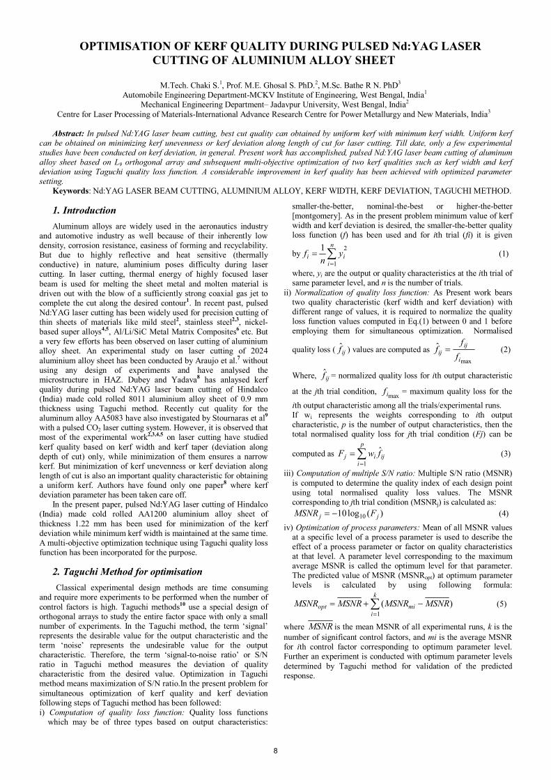
3. Experiment In the present investigation, experiment has been carried out
using a 135 W pulsed Nd:YAG laser (Model JK-704, GSI Lumonics) machining system with CNC work table as shown in Fig 1. Oxygen is used as an assist gas. The controllable input process parameters considered are cutting speed (V), pulse energy (E), pulse width (P) and assist gas pressure (P). Focal length of lens (120 mm), nozzle diameter (1.5 mm), stand off distance (6.0 mm) and spot diameter (0.24 mm) are kept constant throughout the experimentation while focus position is kept at the job surface.
Fig.1. Experimental setup
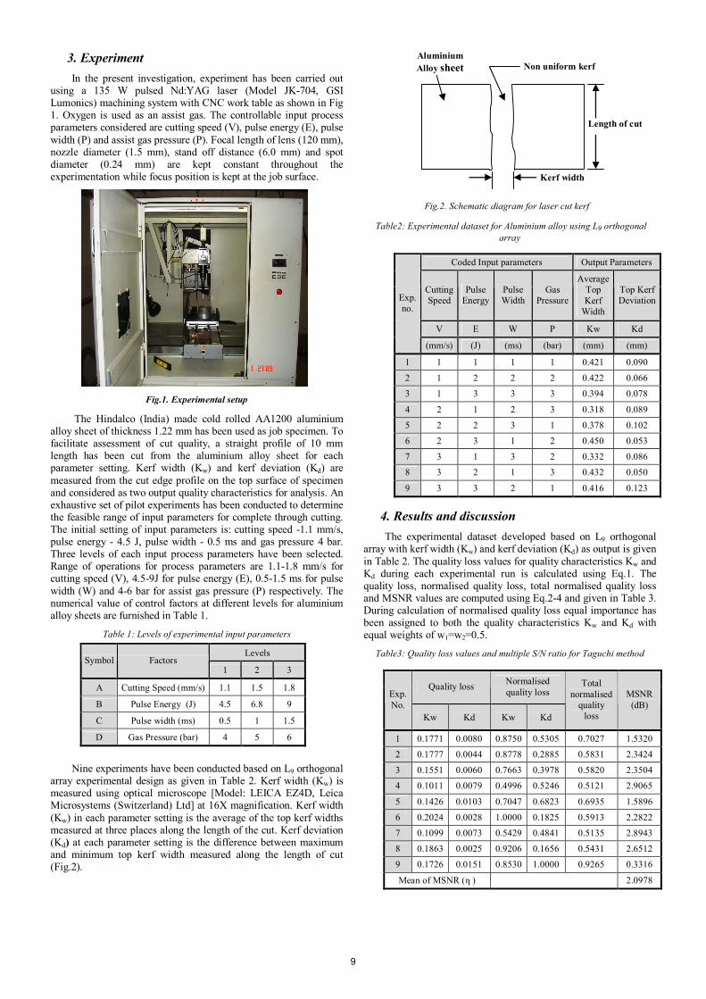
The Hindalco (India) made cold rolled AA1200 aluminium alloy sheet of thickness 1.22 mm has been used as job specimen. To facilitate assessment of cut quality, a straight profile of 10 mm length has been cut from the aluminium alloy sheet for each parameter setting. Kerf width (Kw) and kerf deviation (Kd) are measured from the cut edge profile on the top surface of specimen and considered as two output quality characteristics for analysis. An exhaustive set of pilot experiments has been conducted to determine the feasible range of input parameters for complete through cutting. The initial setting of input parameters is: cutting speed -1.1 mm/s, pulse energy - 4.5 J, pulse width - 0.5 ms and gas pressure 4 bar. Three levels of each input process parameters have been selected. Range of operations for process parameters are 1.1-1.8 mm/s for cutting speed (V), 4.5-9J for pulse energy (E), 0.5-1.5 ms for pulse width (W) and 4-6 bar for assist gas pressure (P) respectively. The numerical value of control factors at different levels for aluminium alloy sheets are furnished in Table 1.
Table 1: Levels of experimental input parameters
Nine experiments have been conducted based on L9 orthogonal array experimental design as given in Table 2. Kerf width (Kw) is measured using optical microscope [Model: LEICA EZ4D, Leica Microsystems (Switzerland) Ltd] at 16X magnification. Kerf width (Kw) in each parameter setting is the average of the top kerf widths measured at three places along the length of the cut. Kerf deviation (Kd) at each parameter setting is the difference between maximum and minimum top kerf width measured along the length of cut (Fig.2).
Fig.2. Schematic diagram for laser cut kerf
Table2: Experimental dataset for Aluminium alloy using L9 orthogonal array
4. Results and discussion The experimental dataset developed based on L9 orthogonal
array with kerf width (Kw) and kerf deviation (Kd) as output is given in Table 2. The quality loss values for quality characteristics Kw and Kd during each experimental run is calculated using Eq.1. The quality loss, normalised quality loss, total normalised quality loss and MSNR values are computed using Eq.2-4 and given in Table 3. During calculation of normalised quality loss equal importance has been assigned to both the quality characteristics Kw and Kd with equal weights of w1=w2=0.5.
Table3: Quality loss values and multiple S/N ratio for Taguchi method
Coded Input parameters Output Parameters
Cutting Speed
Pulse Energy
Pulse Width
Gas Pressure
Average Top Kerf
Width
Top Kerf Deviation
V E W P Kw Kd
Exp. no.
(mm/s) (J) (ms) (bar) (mm) (mm)
1 1 1 1 1 0.421 0.090
2 1 2 2 2 0.422 0.066
3 1 3 3 3 0.394 0.078
4 2 1 2 3 0.318 0.089
5 2 2 3 1 0.378 0.102
6 2 3 1 2 0.450 0.053
7 3 1 3 2 0.332 0.086
8 3 2 1 3 0.432 0.050
9 3 3 2 1 0.416 0.123
Levels Symbol Factors
1 2 3
A Cutting Speed (mm/s) 1.1 1.5 1.8
B Pulse Energy (J) 4.5 6.8 9
C Pulse width (ms) 0.5 1 1.5
D Gas Pressure (bar) 4 5 6
Quality loss Normalised quality loss Exp.
No. Kw Kd Kw Kd
Total normalised
quality loss
MSNR (dB)
1 0.1771 0.0080 0.8750 0.5305 0.7027 1.5320
2 0.1777 0.0044 0.8778 0.2885 0.5831 2.3424
3 0.1551 0.0060 0.7663 0.3978 0.5820 2.3504
4 0.1011 0.0079 0.4996 0.5246 0.5121 2.9065
5 0.1426 0.0103 0.7047 0.6823 0.6935 1.5896
6 0.2024 0.0028 1.0000 0.1825 0.5913 2.2822
7 0.1099 0.0073 0.5429 0.4841 0.5135 2.8943
8 0.1863 0.0025 0.9206 0.1656 0.5431 2.6512
9 0.1726 0.0151 0.8530 1.0000 0.9265 0.3316
Mean of MSNR (η ) 2.0978
Kerf width
Length of cut
Non uniform kerf Aluminium Alloy sheet
9
The effect of different operating parameters on multiple S/N ratio comprising Kw and Kd is shown in Table 4 and Fig.3. It is clear that, optimum levels of different control factors for obtaining minimum kerf width and kerf deviation are: cutting speed at level 2 (1.5mm/s), pulse energy at level 1(4.5J), pulse width at level 3 (1.5ms) and gas pressure at level 3 (6 bar). Relative contribution of the controlling parameters on kerf quality is shown in Table 4.
Table4: Effect of factor on multiple S/N ratio
0.5
1.0
1.5
2.0
2.5
3.0
0 1 2 3 4Levels of Factors
Mul
tiple
S/N
Rat
io (d
B)
Cutting SpeedPulse EnergyPulse WidthGas Pressure
Fig.3. Effect of factor levels on multiple S/N ratio
Analysis of variance (ANOVA) is a statistical technique for
quantitative estimation of relative contribution of each control factor or parameter on overall measured response. The relative significance of factors is often represented in terms of F-ratio or in terms of percentage contribution10. Greater the F-ratio indicates more significant will be the factor. In the present work, ANOVA is employed for analyzing significance of controlling parameters V, E, W and P on combined kerf quality parameter and is given in Table 5.
Table5: Results of ANOVA for multiple kerf quality(Kd and Kw )
An estimate of the sum of squares for the pooled error can be obtained by pooling the sum of squares of factors with the lowest sum of squares- cutting speed and pulse width. The pooled error has 4 degrees of freedom and a sum of squares of 0.4183. Hence the pooled mean square error is 0.1046. The F value can be found using the ratio of mean square of a factor to variance of pooled error. High F values indicate all the factors V, E, W and P are significant for determination of kerf quality.
Further, highest F-ratio of 19.4472 indicates gas pressure (P) as most significant control factor with percentage contribution of 74.41% for kerf quality, while cutting speed is found as least significant factor. The percentage contribution of different control factors on combined kerf quality parameter for aluminium alloys in increasing order are: cutting speed (2.55%), pulse width (5.11%), pulse energy (17.93%) and gas pressure (74.14%).
Table6: Results of validation experiment at optimum parameter level
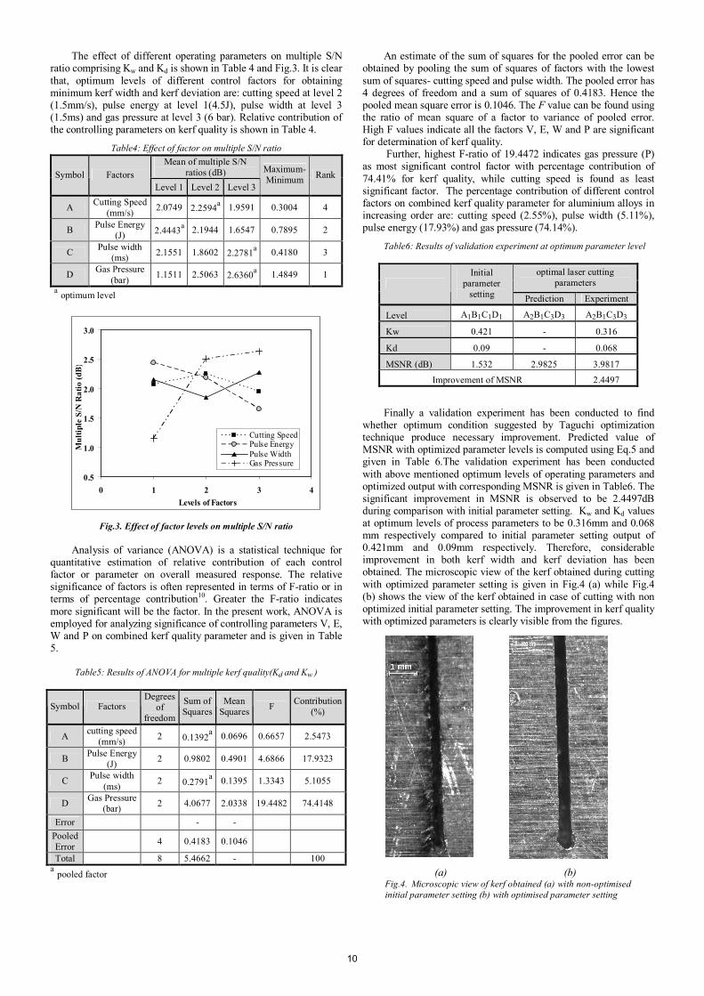
Finally a validation experiment has been conducted to find whether optimum condition suggested by Taguchi optimization technique produce necessary improvement. Predicted value of MSNR with optimized parameter levels is computed using Eq.5 and given in Table 6.The validation experiment has been conducted with above mentioned optimum levels of operating parameters and optimized output with corresponding MSNR is given in Table6. The significant improvement in MSNR is observed to be 2.4497dB during comparison with initial parameter setting. Kw and Kd values at optimum levels of process parameters to be 0.316mm and 0.068 mm respectively compared to initial parameter setting output of 0.421mm and 0.09mm respectively. Therefore, considerable improvement in both kerf width and kerf deviation has been obtained. The microscopic view of the kerf obtained during cutting with optimized parameter setting is given in Fig.4 (a) while Fig.4 (b) shows the view of the kerf obtained in case of cutting with non optimized initial parameter setting. The improvement in kerf quality with optimized parameters is clearly visible from the figures.
Mean of multiple S/N ratios (dB) Symbol Factors
Level 1 Level 2 Level 3
Maximum- Minimum Rank
A Cutting Speed (mm/s) 2.0749 2.2594a 1.9591 0.3004 4
B Pulse Energy (J) 2.4443a 2.1944 1.6547 0.7895 2
C Pulse width (ms) 2.1551 1.8602 2.2781a 0.4180 3
D Gas Pressure (bar) 1.1511 2.5063 2.6360a 1.4849 1
a optimum level
Symbol Factors Degrees
of freedom
Sum of Squares
Mean Squares F Contribution
(%)
A cutting speed (mm/s) 2 0.1392a 0.0696 0.6657 2.5473
B Pulse Energy (J) 2 0.9802 0.4901 4.6866 17.9323
C Pulse width (ms) 2 0.2791a 0.1395 1.3343 5.1055
D Gas Pressure (bar) 2 4.0677 2.0338 19.4482 74.4148
Error - - Pooled Error
4 0.4183 0.1046
Total 8 5.4662 - 100 a pooled factor
optimal laser cutting parameters
Initial parameter
setting Prediction Experiment
Level A1B1C1D1 A2B1C3D3 A2B1C3D3
Kw 0.421 - 0.316
Kd 0.09 - 0.068
MSNR (dB) 1.532 2.9825 3.9817
Improvement of MSNR 2.4497
(a) (b)
Fig.4. Microscopic view of kerf obtained (a) with non-optimised initial parameter setting (b) with optimised parameter setting
10
5. Conclusion In present work, multi-objective optimisation of kerf quality
based on kerf width and kerf deviation has been carried out using Taguchi method for pulsed laser cutting of thin sheet of aluminium alloy. Following conclusions can be drawn on the basis of results obtained:
(i) Results of Taguchi optimization indicates that best kerf quality ie minimum kerf width and minimum kerf deviation for aluminium alloy sheet of 1.22 mm thickness can be achieved by operating with input parameter setting of cutting speed =1.5mm/s, pulse energy = 4.5 J , pulse width =1.5ms and gas pressure = 6 bar .
(ii) Assist gas pressure significantly affects the kerf quality in the operating range of process parameters.
(iii) The kerf width and kerf deviation has been reduced up to 0.316mm and 0.068 mm respectively compared to initial value of kerf width and kerf deviation as 0.421mm and 0.09mm respectively.
(iv) The multiple S/N ratio compared to initial conditions has been improved by 2.4497dB.
6. References: 1. Steen, WM Laser Material Processing. Springer, 2005. 2. Kaebernick H. Theoretical and experimental investigation of
pulsed laser cutting - Annals of the CIRP, 48(1), 1999, 163–166, (Kaebernick, H., D. Bicleanu, M. Brandt).
3. Ghany KA. Cutting of 1.2mm thick austenitic stainless steel sheet using pulsed and CW Nd:YAG laser - Journal of Materials Processing Technology,168, 2005,438–447,( Ghany, K.A., M. Newishy)
4. Thawari G. Influence of process parameters during pulsed Nd:YAG laser cutting of nickel-base superalloys - Journal of Materials Processing Technology, 170, 2005, 229–239, (Thawari, G., J.K. Sarin Sundar, G. Sundararajan, S.V. Joshi)
5. Dubey AK. Multi-objective optimization of Nd:YAG laser cutting of nickel-based superalloy sheet using orthogonal array with principal component analysis- Optics and Lasers in Engineering, 46, 2008, 124–132,( Dubey A.K.,V. Yadava).
6. Yue TM, Pulsed Nd:YAG Laser Cutting of Al/Li/SiC Metal Matrix Composites - Materials and Manufacturing Processes, 11(1), 1996, 17–29 (Yue, T.M., W. S. Lau.).
7. Araujo D. Microstructural study of CO2 laser machined heat affected zone of 2024 aluminium alloy-Applied Surface Science, 208/209,2003, 210–217 (Araujo D., F.J. Carpio, D. Mendez, A.J. Garcia, M.P. Villar, R. Garcia, D. Jimenez, L. Rubio)
8. Dubey AK. Optimization of kerf quality during pulsed laser cutting of aluminium alloy sheet- Journal of Materials Processing Technology, 204, 2008, 412–418, ( Dubey A.K.,V. Yadava).
9. Stournaras A. An investigation of quality in CO2 laser cutting of aluminum- CIRP Journal of Manufacturing Science and Technology, 2(1), 2009, 61-69, ( P. Stavropoulos, K. Salonitis, G. Chryssolouris).
10. Montgomery DC. Design and analysis of experiments, New York: Wiley, 5th Edition, 2001.
11