Embed Size (px)
Citation preview
Ballast Paver™ Design & Installation Guide
• Size: 11-3/4” x 16-1/2” x 1-1/2” • Weight: 12 ± 0.75 lbs. per square foot • Compressive strength: 5,000 psi @ 28 days
cure • Density: 125 pcf • Water absorption: 5% nominal • Performance testing: ICC-ES 4338
• Interlocking design provides superior wind resistance • Easiest paver to install • Four way drainage • Smooth, rounded bearing pads protect the membrane from abrasion • Durable • Fireproof • Freeze / thaw resistant
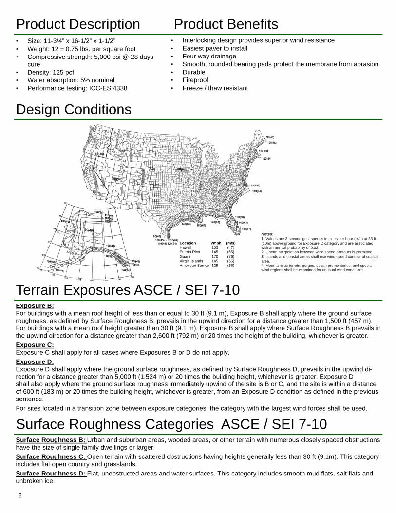
Design Conditions
Terrain Exposures ASCE / SEI 7-10 Exposure B: For buildings with a mean roof height of less than or equal to 30 ft (9.1 m), Exposure B shall apply where the ground surface roughness, as defined by Surface Roughness B, prevails in the upwind direction for a distance greater than 1,500 ft (457 m). For buildings with a mean roof height greater than 30 ft (9.1 m), Exposure B shall apply where Surface Roughness B prevails in the upwind direction for a distance greater than 2,600 ft (792 m) or 20 times the height of the building, whichever is greater. Exposure C: Exposure C shall apply for all cases where Exposures B or D do not apply. Exposure D: Exposure D shall apply where the ground surface roughness, as defined by Surface Roughness D, prevails in the upwind di-rection for a distance greater than 5,000 ft (1,524 m) or 20 times the building height, whichever is greater. Exposure D shall also apply where the ground surface roughness immediately upwind of the site is B or C, and the site is within a distance of 600 ft (183 m) or 20 times the building height, whichever is greater, from an Exposure D condition as defined in the previous sentence. For sites located in a transition zone between exposure categories, the category with the largest wind forces shall be used.
Surface Roughness Categories ASCE / SEI 7-10 Surface Roughness B: Urban and suburban areas, wooded areas, or other terrain with numerous closely spaced obstructions have the size of single family dwellings or larger. Surface Roughness C: Open terrain with scattered obstructions having heights generally less than 30 ft (9.1m). This category includes flat open country and grasslands. Surface Roughness D: Flat, unobstructed areas and water surfaces. This category includes smooth mud flats, salt flats and unbroken ice.
Notes: 1. Values are 3-second gust speeds in miles per hour (m/s) at 33 ft. (10m) above ground for Exposure C category and are associated with an annual probability of 0.02. 2. Linear interpolation between wind speed contours is permitted. 3. Islands and coastal areas shall use wind speed contour of coastal area. 4. Mountainous terrain, gorges, ocean promontories, and special wind regions shall be examined for unusual wind conditions.
Location Vmph (m/s) Hawaii 105 (47) Puerto Rico 145 (65) Guam 170 (76) Virgin Islands 145 (65) American Samoa 125 (56)
Product Description Product Benefits
2
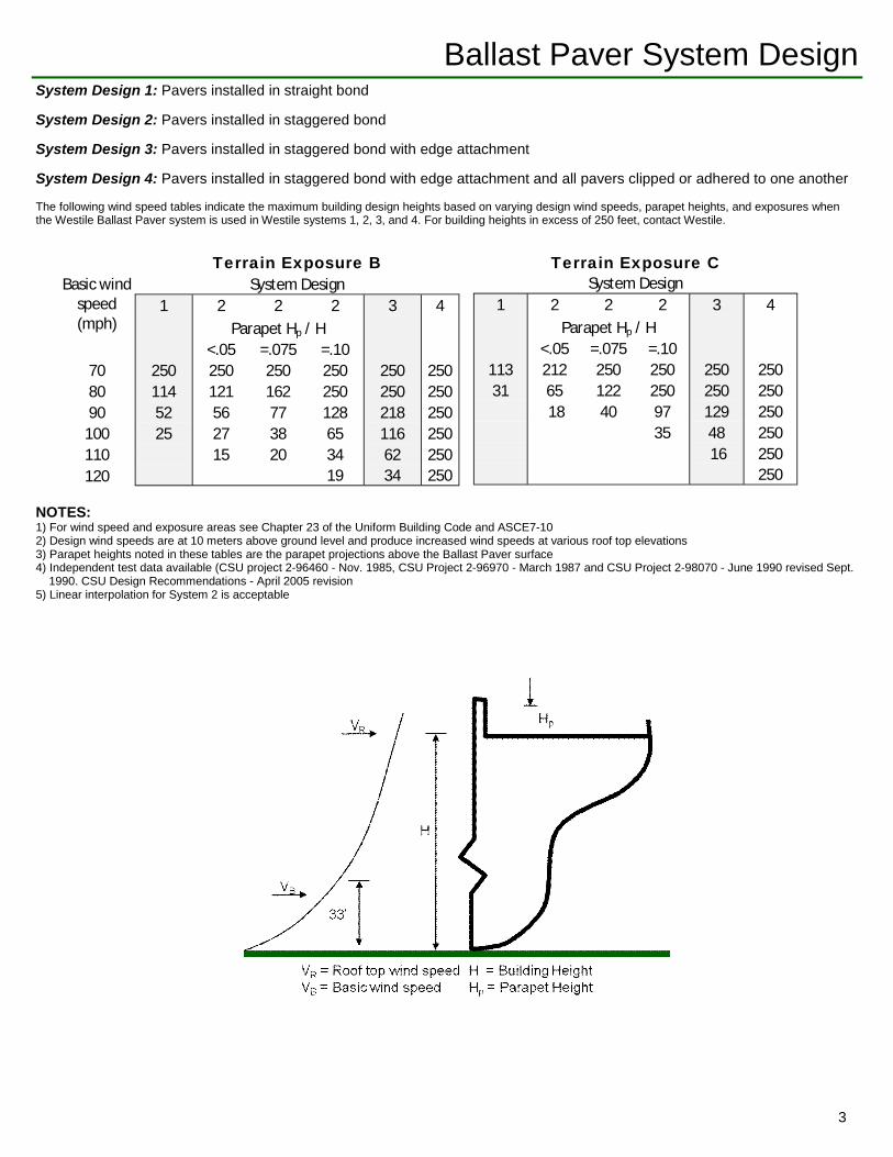
The following wind speed tables indicate the maximum building design heights based on varying design wind speeds, parapet heights, and exposures when the Westile Ballast Paver system is used in Westile systems 1, 2, 3, and 4. For building heights in excess of 250 feet, contact Westile.
System Design 1: Pavers installed in straight bond
System Design 2: Pavers installed in staggered bond
System Design 3: Pavers installed in staggered bond with edge attachment
System Design 4: Pavers installed in staggered bond with edge attachment and all pavers clipped or adhered to one another
Ballast Paver System Design
Terrain Exposure B Basic wind
speed (mph)
System Design 1 2 2 2 3 4 Parapet Hp / H
<.05 =.075 =.10 70 250 250 250 250 250 250 80 114 121 162 250 250 250 90 52 56 77 128 218 250
100 25 27 38 65 116 250 110 15 20 34 62 250 120 19 34 250
Terrain Exposure C System Design
1 2 2 2 3 4 Parapet Hp / H <.05 =.075 =.10
113 212 250 250 250 250 31 65 122 250 250 250 18 40 97 129 250 35 48 250 16 250 250
NOTES: 1) For wind speed and exposure areas see Chapter 23 of the Uniform Building Code and ASCE7-10 2) Design wind speeds are at 10 meters above ground level and produce increased wind speeds at various roof top elevations 3) Parapet heights noted in these tables are the parapet projections above the Ballast Paver surface 4) Independent test data available (CSU project 2-96460 - Nov. 1985, CSU Project 2-96970 - March 1987 and CSU Project 2-98070 - June 1990 revised Sept. 1990. CSU Design Recommendations - April 2005 revision 5) Linear interpolation for System 2 is acceptable
3
Ballast Paver System Design
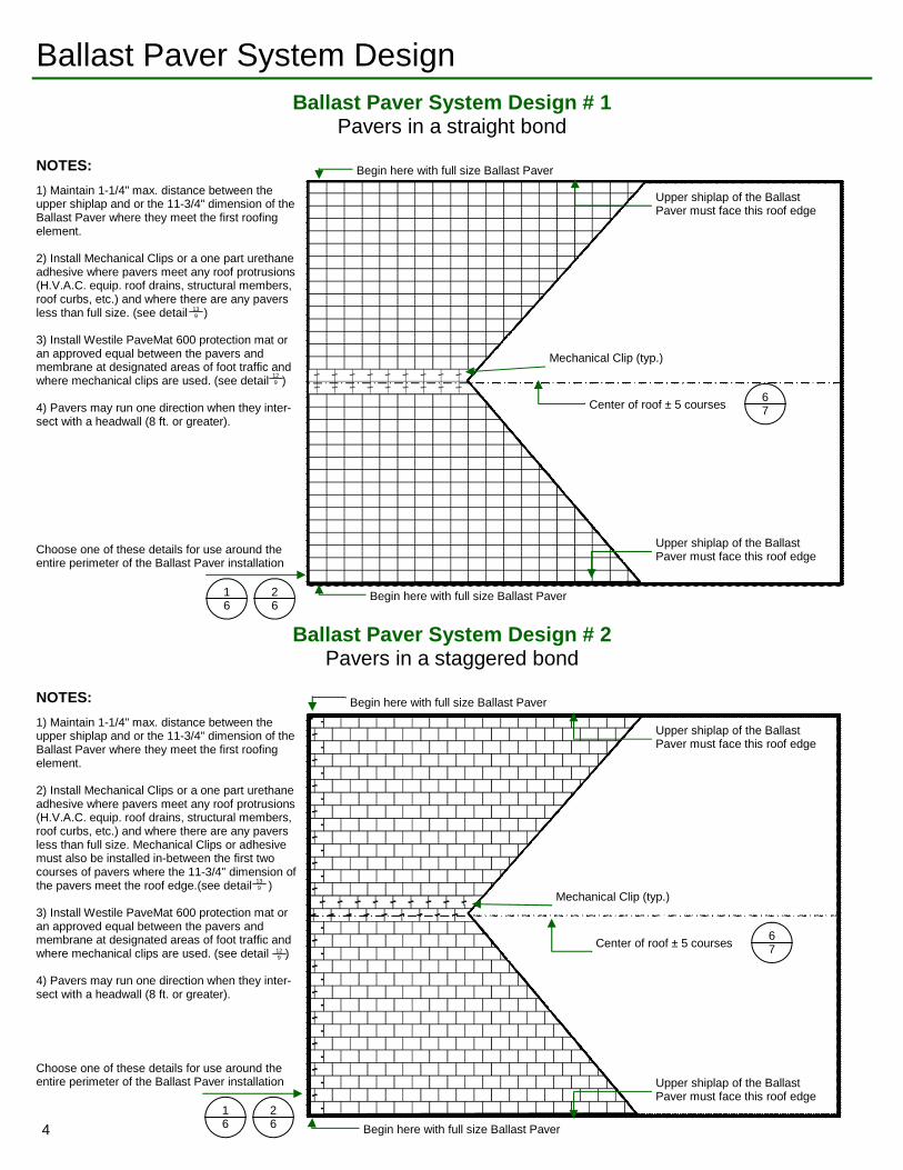
Mechanical Clip (typ.)
Center of roof ± 5 courses 6 7
Mechanical Clip (typ.)
Center of roof ± 5 courses 6 7
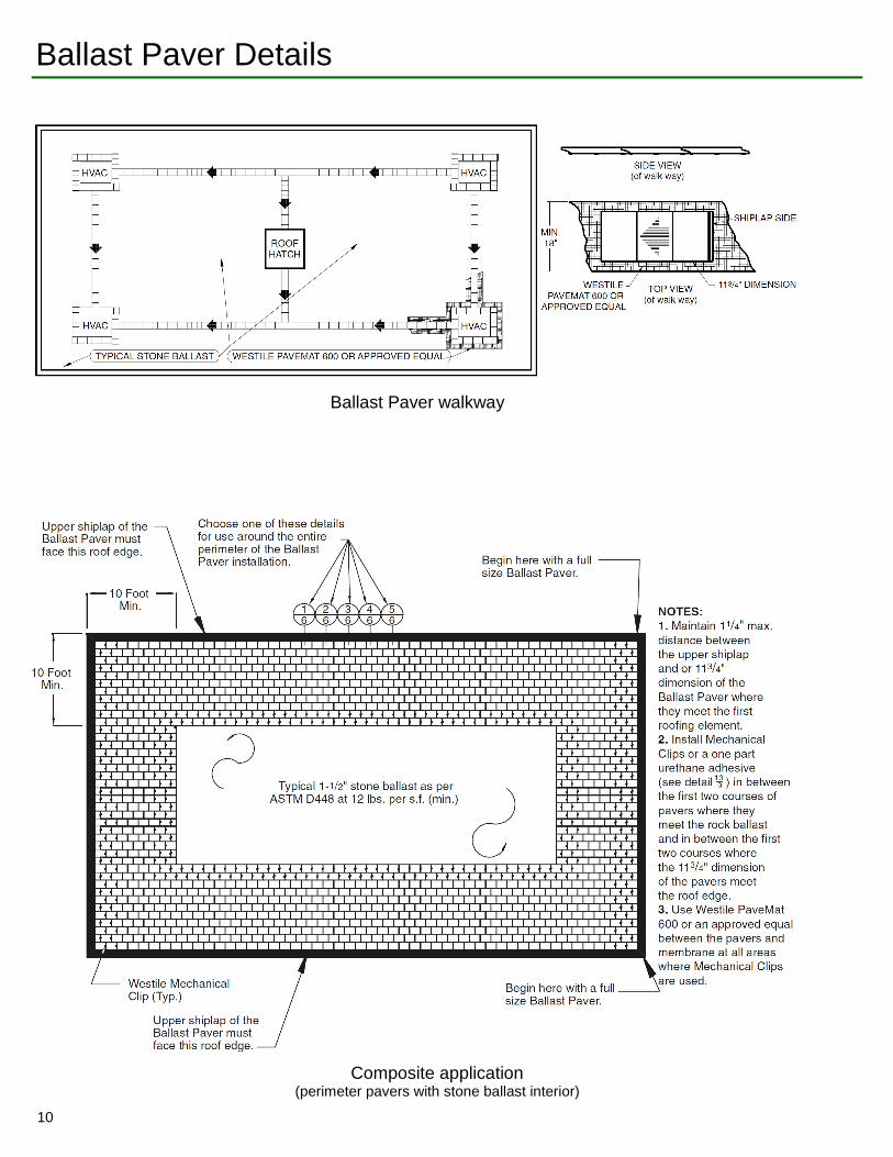
1) Maintain 1-1/4" max. distance between the upper shiplap and or the 11-3/4" dimension of the Ballast Paver where they meet the first roofing element. 2) Install Mechanical Clips or a one part urethane adhesive where pavers meet any roof protrusions (H.V.A.C. equip. roof drains, structural members, roof curbs, etc.) and where there are any pavers less than full size. Mechanical Clips or adhesive must also be installed in-between the first two courses of pavers where the 11-3/4" dimension of the pavers meet the roof edge.(see detail ) 3) Install Westile PaveMat 600 protection mat or an approved equal between the pavers and membrane at designated areas of foot traffic and where mechanical clips are used. (see detail ) 4) Pavers may run one direction when they inter-sect with a headwall (8 ft. or greater).
NOTES:
13 9
12 9
1) Maintain 1-1/4" max. distance between the upper shiplap and or the 11-3/4" dimension of the Ballast Paver where they meet the first roofing element. 2) Install Mechanical Clips or a one part urethane adhesive where pavers meet any roof protrusions (H.V.A.C. equip. roof drains, structural members, roof curbs, etc.) and where there are any pavers less than full size. (see detail ) 3) Install Westile PaveMat 600 protection mat or an approved equal between the pavers and membrane at designated areas of foot traffic and where mechanical clips are used. (see detail ) 4) Pavers may run one direction when they inter-sect with a headwall (8 ft. or greater).
NOTES:
13 9
12 9
Ballast Paver System Design # 1 Pavers in a straight bond
Ballast Paver System Design # 2 Pavers in a staggered bond
Upper shiplap of the Ballast Paver must face this roof edge
Upper shiplap of the Ballast Paver must face this roof edge
Upper shiplap of the Ballast Paver must face this roof edge
Upper shiplap of the Ballast Paver must face this roof edge
Begin here with full size Ballast Paver
Begin here with full size Ballast Paver
Begin here with full size Ballast Paver
Begin here with full size Ballast Paver
Choose one of these details for use around the entire perimeter of the Ballast Paver installation
1 6
2 6
1 6
2 6
Choose one of these details for use around the entire perimeter of the Ballast Paver installation
4
Ballast Paver System Design
Mechanical Clip (typ.)
Center of roof ± 5 courses 6 7
Mechanical Clip (typ.)
Center of roof ± 5 courses 6 7
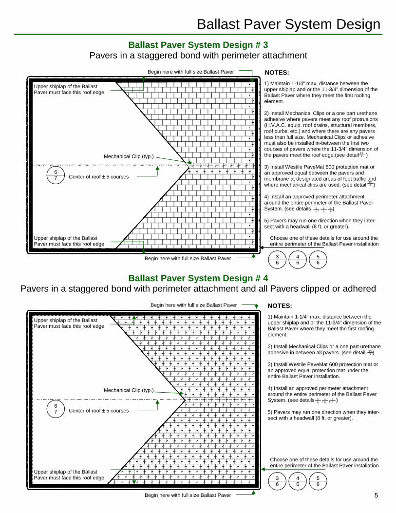
1) Maintain 1-1/4" max. distance between the upper shiplap and or the 11-3/4" dimension of the Ballast Paver where they meet the first roofing element. 2) Install Mechanical Clips or a one part urethane adhesive where pavers meet any roof protrusions (H.V.A.C. equip. roof drains, structural members, roof curbs, etc.) and where there are any pavers less than full size. Mechanical Clips or adhesive must also be installed in-between the first two courses of pavers where the 11-3/4" dimension of the pavers meet the roof edge.(see detail ) 3) Install Westile PaveMat 600 protection mat or an approved equal between the pavers and membrane at designated areas of foot traffic and where mechanical clips are used. (see detail ) 4) Install an approved perimeter attachment around the entire perimeter of the Ballast Paver System. (see details , , ) 5) Pavers may run one direction when they inter-sect with a headwall (8 ft. or greater).
NOTES:
13 9
12 9
3 6
4 6
5 6
1) Maintain 1-1/4" max. distance between the upper shiplap and or the 11-3/4" dimension of the Ballast Paver where they meet the first roofing element. 2) Install Mechanical Clips or a one part urethane adhesive in between all pavers. (see detail ) 3) Install Westile PaveMat 600 protection mat or an approved equal protection mat under the entire Ballast Paver installation. 4) Install an approved perimeter attachment around the entire perimeter of the Ballast Paver System. (see details , , ) 5) Pavers may run one direction when they inter-sect with a headwall (8 ft. or greater).
NOTES:
13 9
3 6
4 6
5 6
Ballast Paver System Design # 3 Pavers in a staggered bond with perimeter attachment
Ballast Paver System Design # 4 Pavers in a staggered bond with perimeter attachment and all Pavers clipped or adhered
Upper shiplap of the Ballast Paver must face this roof edge
Upper shiplap of the Ballast Paver must face this roof edge
Upper shiplap of the Ballast Paver must face this roof edge
Upper shiplap of the Ballast Paver must face this roof edge
Begin here with full size Ballast Paver
Begin here with full size Ballast Paver
Begin here with full size Ballast Paver
Begin here with full size Ballast Paver
Choose one of these details for use around the entire perimeter of the Ballast Paver installation
Choose one of these details for use around the entire perimeter of the Ballast Paver installation
3 6
4 6
5 6
3 6
4 6
5 6
5
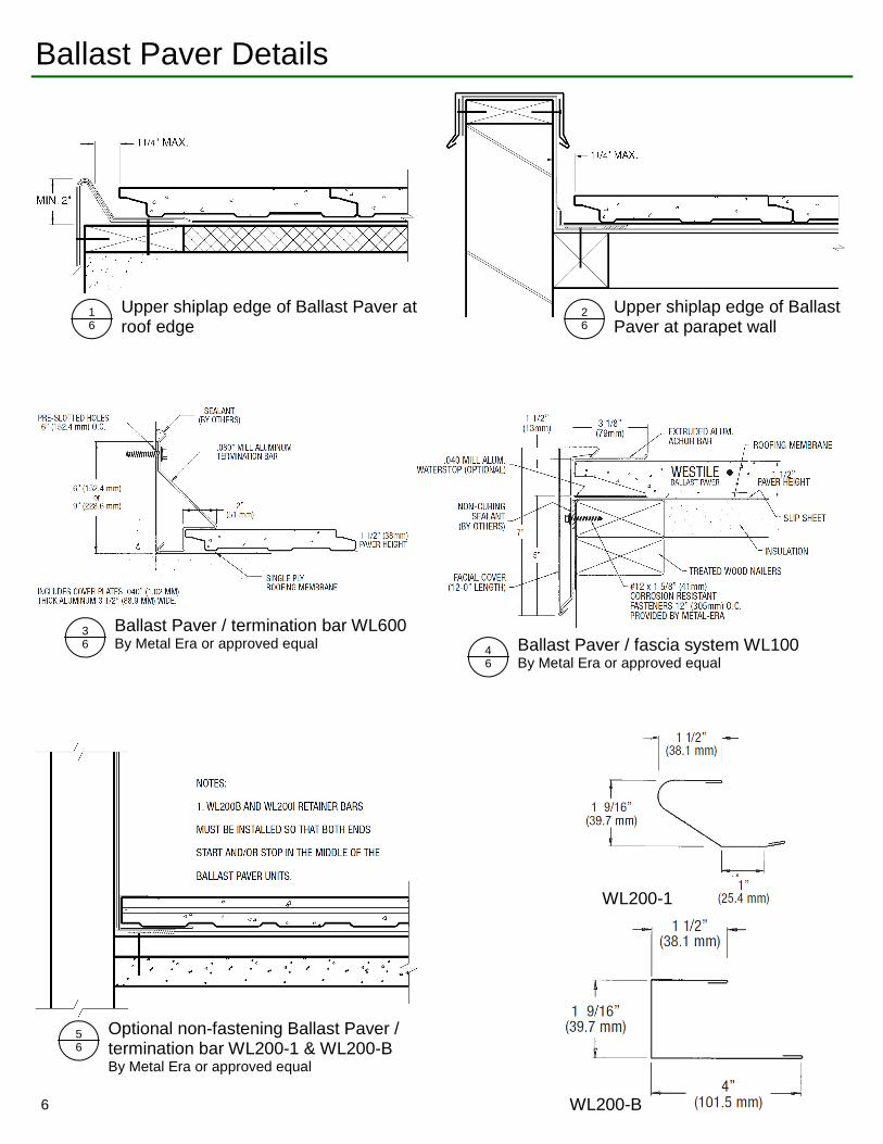
1 6
Upper shiplap edge of Ballast Paver at roof edge
2 6
Upper shiplap edge of Ballast Paver at parapet wall
Ballast Paver Details
3 6
Ballast Paver / termination bar WL600 By Metal Era or approved equal 4
6 Ballast Paver / fascia system WL100 By Metal Era or approved equal
5 6
Optional non-fastening Ballast Paver / termination bar WL200-1 & WL200-B By Metal Era or approved equal
WL200-1
WL200-B 6
Ballast Paver Details
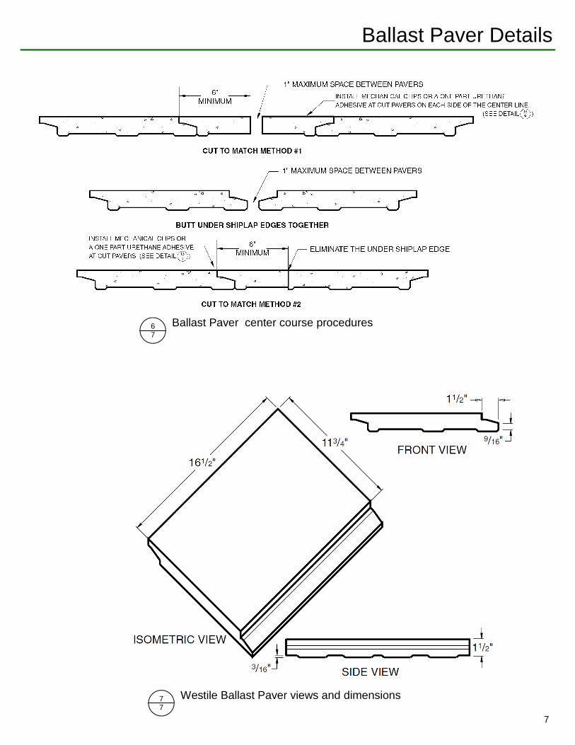
6 7
Ballast Paver center course procedures
7 7
Westile Ballast Paver views and dimensions
7
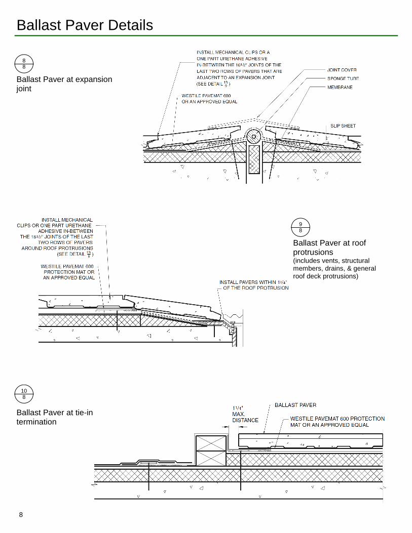
Ballast Paver Details
8 8
Ballast Paver at expansion joint
9 8
Ballast Paver at roof protrusions (includes vents, structural members, drains, & general roof deck protrusions)
10 8
Ballast Paver at tie-in termination
8
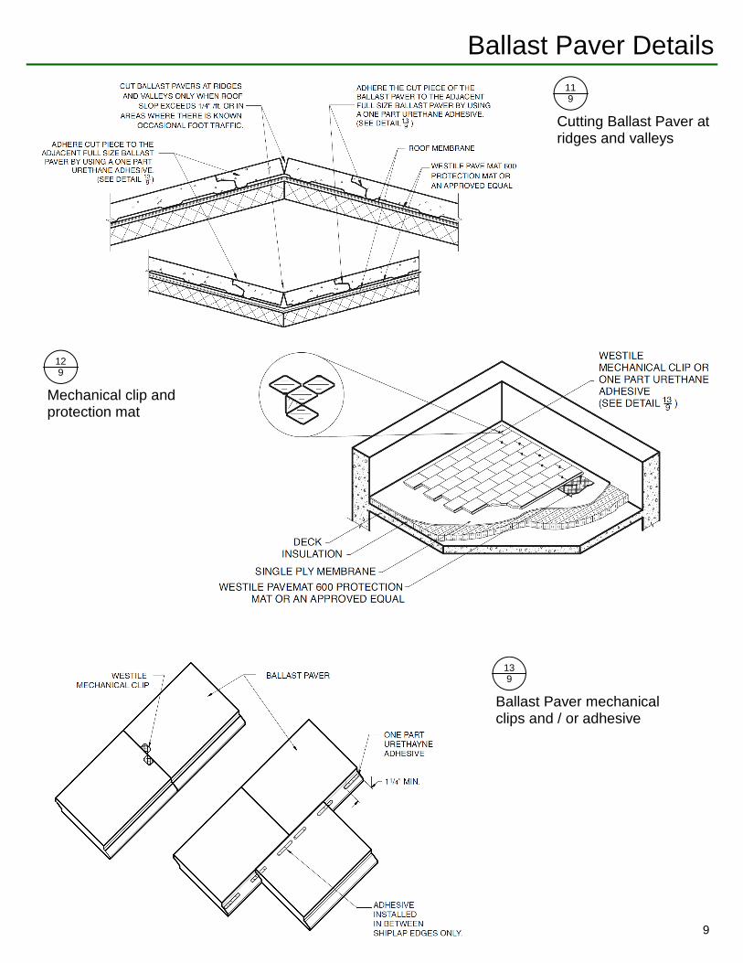
Ballast Paver Details 11 9
Cutting Ballast Paver at ridges and valleys
12 9
Mechanical clip and protection mat
13 9
Ballast Paver mechanical clips and / or adhesive
9
Ballast Paver Details
Ballast Paver walkway
Composite application (perimeter pavers with stone ballast interior)
10
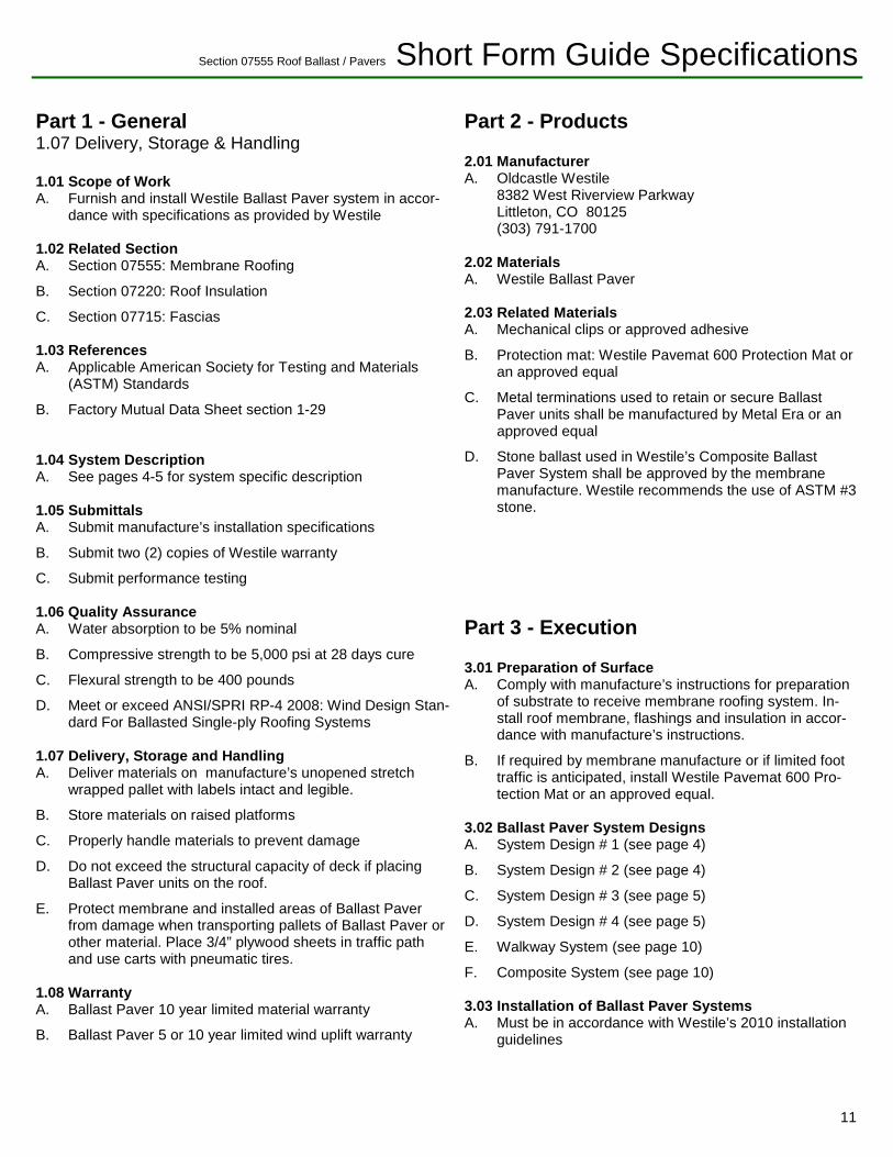
Section 07555 Roof Ballast / Pavers Short Form Guide Specifications
Part 1 - General 1.07 Delivery, Storage & Handling 1.01 Scope of Work A. Furnish and install Westile Ballast Paver system in accor-
dance with specifications as provided by Westile 1.02 Related Section A. Section 07555: Membrane Roofing
B. Section 07220: Roof Insulation
C. Section 07715: Fascias 1.03 References A. Applicable American Society for Testing and Materials
(ASTM) Standards
B. Factory Mutual Data Sheet section 1-29 1.04 System Description A. See pages 4-5 for system specific description 1.05 Submittals A. Submit manufacture’s installation specifications
B. Submit two (2) copies of Westile warranty
C. Submit performance testing 1.06 Quality Assurance A. Water absorption to be 5% nominal
B. Compressive strength to be 5,000 psi at 28 days cure
C. Flexural strength to be 400 pounds
D. Meet or exceed ANSI/SPRI RP-4 2008: Wind Design Stan-dard For Ballasted Single-ply Roofing Systems
1.07 Delivery, Storage and Handling A. Deliver materials on manufacture’s unopened stretch
wrapped pallet with labels intact and legible.
B. Store materials on raised platforms
C. Properly handle materials to prevent damage
D. Do not exceed the structural capacity of deck if placing Ballast Paver units on the roof.
E. Protect membrane and installed areas of Ballast Paver from damage when transporting pallets of Ballast Paver or other material. Place 3/4” plywood sheets in traffic path and use carts with pneumatic tires.
1.08 Warranty A. Ballast Paver 10 year limited material warranty
B. Ballast Paver 5 or 10 year limited wind uplift warranty
Part 2 - Products 2.01 Manufacturer A. Oldcastle Westile
8382 West Riverview Parkway Littleton, CO 80125 (303) 791-1700
2.02 Materials A. Westile Ballast Paver 2.03 Related Materials A. Mechanical clips or approved adhesive
B. Protection mat: Westile Pavemat 600 Protection Mat or an approved equal
C. Metal terminations used to retain or secure Ballast Paver units shall be manufactured by Metal Era or an approved equal
D. Stone ballast used in Westile’s Composite Ballast Paver System shall be approved by the membrane manufacture. Westile recommends the use of ASTM #3 stone.
Part 3 - Execution 3.01 Preparation of Surface A. Comply with manufacture’s instructions for preparation
of substrate to receive membrane roofing system. In-stall roof membrane, flashings and insulation in accor-dance with manufacture’s instructions.
B. If required by membrane manufacture or if limited foot traffic is anticipated, install Westile Pavemat 600 Pro-tection Mat or an approved equal.
3.02 Ballast Paver System Designs A. System Design # 1 (see page 4)
B. System Design # 2 (see page 4)
C. System Design # 3 (see page 5)
D. System Design # 4 (see page 5)
E. Walkway System (see page 10)
F. Composite System (see page 10) 3.03 Installation of Ballast Paver Systems A. Must be in accordance with Westile’s 2010 installation
guidelines
11
Westile, Inc. An Oldcastle™ Company 8382 West Riverview Parkway Littleton, CO 80125 (800) 433-8453 For more information, visit our website at www.westile.com
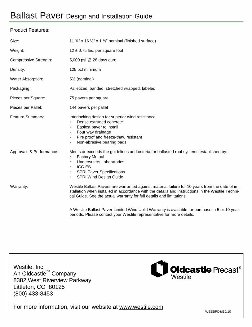
Ballast Paver Design and Installation Guide
Product Features: Size: 11 ¾” x 16 ½” x 1 ½” nominal (finished surface) Weight: 12 ± 0.75 lbs. per square foot Compressive Strength: 5,000 psi @ 28 days cure Density: 125 pcf minimum Water Absorption: 5% (nominal) Packaging: Palletized, banded, stretched wrapped, labeled Pieces per Square: 75 pavers per square Pieces per Pallet: 144 pavers per pallet Feature Summary: Interlocking design for superior wind resistance
• Dense extruded concrete • Easiest paver to install • Four way drainage • Fire proof and freeze-thaw resistant • Non-abrasive bearing pads
Approvals & Performance: Meets or exceeds the guidelines and criteria for ballasted roof systems established by:
• Factory Mutual • Underwriters Laboratories • ICC-ES • SPRI Paver Specifications • SPRI Wind Design Guide
Warranty: Westile Ballast Pavers are warranted against material failure for 10 years from the date of in-
stallation when installed in accordance with the details and instructions in the Westile Techni-cal Guide. See the actual warranty for full details and limitations.
A Westile Ballast Paver Limited Wind Uplift Warranty is available for purchase in 5 or 10 year periods. Please contact your Westile representative for more details.
WESBPD&I10/10