Embed Size (px)
Citation preview

Alwayse Engineering LimitedAlwayse Engineering was established in 1939when a small engineering company, SheridanTools, was purchased. Later its name was changedto “Alwayse” meaning that the units are multi-directional and move in all directions or ways -hence “Alwayse”. The distinctive spelling adds tothe company’s individuality.
The present chairman, Mr L.W. Pinnick, has over-seen its growth and development since the late1940s.
Alwayse Ball Transfer Units are used as part of aconveyor or material handling system to enableloads both light and heavy, to be moved or trans-
ferred in any direction. As the originators of theBall Transfer Unit over 50 years ago, we havebecome an important part of the material han-dling industry.
Whether ball units are used for loading/feedingmachines, moving goods/materials, as an alterna-tive to a castor, or in a form of linear operation,they have become an integral part of industryand provide an important and essential service.
Alwayse Ball Units are used in all industriesthroughout the World and over 2,000,000 aresold every year.
Ball Transfer Units
Alwayse Engineering LimitedWarner StreetBirmingham B12 OJGEngland
Telephone: 0121 772 8481(International): 44 121 772 8481
Fax: 0121 771 0327(International): 44 121 771 0327
Home page: www.alwayse.co.ukE-mail: [email protected]
FREE Technical Advice:We offer a free technical advice ser-vice - if you are unsure of the correctball unit to use, ask us. We do notaccept liability for the choice of unitif we are not consulted.

IMPORTANT - IF YOU ARE UNSURE, CONSULT OUR FREE TECHNICAL SERVICE. TELEPHONE: 0121 772 8481 FACSIMILE: 0121 771 0327
TECHNICAL INFORMATION
DESIGN & CONSTRUCTION
Alwayse ball units are a multi-direc-tional, material handling system, manu-factured from high quality materials inour Birmingham factory.
They consist of a large load-bearingball which sits upon many small ballsencapsulated in a hemi-spherical cup.The housing can contain a seal to cleanthe load ball as it rotates. The designgreatly reduces friction and allowsheavy loads to be moved with a mini-mum of effort.
Our ball units may be used at any ori-entation but deviation from the verti-cal may result in a reduction in thestated load ratings quoted in this cata-logue.
FIXING METHODS
There are various methods of fixingAlwayse ball units. A wide range of fit-tings enable them to be used with vari-ous different materials.
Fixing clips are available for mostdesigns - see pages 28 & 29.
MATERIALS
Alwayse ball units are available in vari-ous materials. The material requiredfor your ball units should be quotedwhen ordering - see page 3 for order-ing details.
LubricationEach unit is pre-lubricated during man-ufacture and normally does not requirefurther attention. In certain instanceswe will advise on lubrication. Greasingor oil points can be incorporated insome units.
CleaningA suitable cleaning or release fluidshould be used in dirty conditions. Forwashing, a suitable detergent such asparaffin, for freeing, a suitable agentsuch as WD40 - please consult technicalsupport.
Most designs have dirt exit holes incor-porated in the bearing cup, or thesecan be added on request.
Shock LoadsWhen calculating loads, consider thepossibility of impact caused by incor-rect levels. Spring loaded units willreduce wear and tear if there are regu-lar shock impacts. Shock loading canalso be reduced by fitting compressiblepads.
Ball units can also be made retractableby other means, such as pneumatic orhydraulic cylinders, cams or levers. Theycan be programmed to operate insequence. All stated loads in thecatalogue are dynamic loads.
Self LevellingCan be achieved by fitting rubber pads.This reduces excessive loads on just afew units. Details on request.
Temperature RangeMin. -30ºc to max. +70ºc continuous, or+100ºc intermittent. Special seals mayneed to be fitted to suit extreme condi-tions. In clean conditions and withoutseals +150ºc to +200ºc are possible,using Type 15 units at reduced loads.
Conveying SpeedMaximum recommended conveyingspeed is 1 metre per second for steelload balls and 0.25 metres per secondfor nylon.
SealsThese help resist ingress of dirt andswarf. They can be omitted onrequest.Woollen felt seals fitted asstandard.
Breakaway Coefficient of FrictionThe average breakaway friction for new ball units containing steel balls ina good working environment is 0.01 to0.015 (1% to 1.5% of the load) and0.02 to 0.025 (2% to 2.5%) for unitswith felt seals.
BALL TABLESRed arrows indicate ideal movement.
Square Pitch Diamond Pitch
Elongated Pitch ElongatedDiagonal Pitch
Vee location
QUANTITY CALCULATIONThe weight of the article to be con-veyed should be divided by 3. Theresult will give the maximum load anysingle ball will bear.On any accurately levelled or flexiblesurface, a number greater than 3 maybe used. The surface hardness and con-dition of the article should be consid-ered to avoid ball unit penetration.
SpacingThe pitch is calculated by dividing thenarrowest dimension by 3·5, i.e. if thenarrowest dimension is 350mm dividedby 3·5=100mm pitchbetween ball centres. Thisensures 3 ball units arealways beneath the nar-rowest dimension of theload at any one time.
Type Load Ball Support Balls Housing
Carbon Carbon Carbon Steel13 Steel Steel Bright Zinc
60-66RC 60-66RC Plated
Nylon Carbon Carbon Steel14
66Chrome Bright Zinc60-66RC Plated
Stainless Steel Stainless Steel Stainless Steel15 AISI 420 AISI 420 AISI 304
52-58RC 52-58RC SelfColour
Stainless Steel Stainless Steel Carbon Steel16 AISI420 AISI 420 Bright Zinc
52-58RC 52-58RC Plated
LOADBALL HOUSING
THREADEDBOLT
SUPPORTBALLS
12
3
4 5
6 7
8 9
2
3·5

TEC
HN
ICA
L I
NFO
RM
ATIO
N
INTERNATIONAL TEL: 44 121 772 8481 INTERNATIONAL FAX: 44 121 771 0327 [email protected] www.alwayse.co.uk
QUICK GUIDE TO THEPRODUCT RANGE
APPLICATIONS
There are many possible applica-tions for Alwayse ball transferunits, where loads need to bemoved smoothly, precisely andwith minimum effort in any direc-tion.
Some typical applications includecargo and baggage handling
(shown above), assembly lines, asa castor, machine loading, sliding-door systems, machine tables, etc.
Alwayse not only advise and sup-ply ball units, but also regularlydesign and manufacture com-plete assemblies ready for cus-tomers to use.
QUALITY
Alwayse Engineering Limitedhave a policy of continuallyimproving the product rangewith new innovative and creativeideas using the latest CNCmachinery and production/inspec-tion methods.
Our specially designed ball unittest machine, regularly used totest production units, togetherwith many years of research andexperience, ensures world-classperformance.
ORDERING PROCEDURE
Alwayse provide a completelyfree technical advice service. Wecan help you select not only themost suitable ball unit for yourapplication, we can advise onevery aspect of layout, design,manufacture and maintenance ofyour installation.
We strongly recommend you takeadvantage of this service.
To Order1) It is generally only necessary toquote the Product ReferenceNumber (i.e. 1009, 1019 or 530-0)and the Material Type (i.e. Type13, 14,15 or 16).
2) There are however instanceswhere more information isrequired.
a) Where applicable the lengthof thread (dimension N) andthe spring washer diameter(dimension W), see pages 6-7& 10-11, also need to be indi-cated, e.g. 3001-13-25 and3004-13-16.9.
b) Also, if applicable, quotethe special specification code.For example,
NO (no oil)NS (no seal)NB (nylon ball)PB (phenolic load ball)DE (dirt exit hole)SI (solid steel inner ring).
Black phenolic balls are availablein ∅19mm and ∅25.4mm loadballs only.
Pages 4,5
Flange Fixing Units
Pages 6,7
Thread Fixing Units
Pages 10,11
Base Fixing Units
Pages 12,13
Mini ball transer units,ball stands, hangerbolts
Pages 8,9
Tube Fixing·Clamp Fixing·Miscellaneous Units
Pages 16,17
Euro Units
Pages 20,21
Hi-Tech, Double Seal,Units
Pages 22,23
Hevi-Load Units 0,1,2 & 3
Pages 24,25
Hevi-Load Units 5,6Die Lifters
Pages 28,29
TUFF Series Heavy DutyUnits
Pages 18,19
Heavy Duty Units,Series 800
Pages 26,27
Spring Loaded Units
Pages 14,15
Glide-Alwayse Units &Fixing Sockets
Pages 30,31
Fixing Clips
Page 32
Tee Blocks, Die Tables
3

IMPORTANT - IF YOU ARE UNSURE, CONSULT OUR FREE TECHNICAL SERVICE. TELEPHONE: 0121 772 8481 FACSIMILE: 0121 771 03274
FLANGE FIXING UNITS
3016 - 4001Features: General purpose. Low profile, dirt exit hole. No seals in3016 and 3025 units.
1010 / 1030Features: Press ball unit into hole to fix, prise out to remove. Unitscan either be fixed or replaced quickly. Low profile, dirt exit hole.
Ball unit Ref. No’s 1022 and 1035 with solid steel inner ring (SI)option illustrated with no seal for improved protection from shockloading.
1502Features: Low profile, high load capacity. Plastic knife edge seal onload ball. Dirt exit hole. Requires 5mm radius on fixing hole. See ‘R’.
2002 XTRA - TUFFeatures: Heavy duty construction, designed for arduous and dirtyconditions. Flushing hole for cleaning, extra large dirt exit hole.
A
C
F
B
E
D
SEATING HOLE O DIA
2 or 3 HOLES H DIAEQUI-SPACED ONG P.C.D.
2 HOLES H DIA
3 HOLES FOR HEAVY DUTY FIXING
A
C
F
B
E
D
SEATING HOLE O DIA
3 HOLES H DIAEQUI-SPACED ONG P.C.D.
L
B
E
CF
D
K
J
G
R
A
C
F
B
E
T
D
O
G

FLA
NG
E F
IXIN
G
UN
ITS
5INTERNATIONAL TEL: 44 121 772 8481 INTERNATIONAL FAX: 44 121 771 0327 [email protected] www.alwayse.co.uk
General Tolerance unless stated ±0.3mmTo order, specify REF Nº and TYPE, i.e. 3016-13.
BALLSIZE(mm)
FIXING HOLES
WEIGHT(KGS)
REF No.
DIMENSIONS (mm) MAXIMUM DYNAMIC LOADING (kg)
3016
3000
3006
3025
1000
1008
1022
1035
2000
2011
4001
2
2
3
2
2
3
3
2
2
32742
32743 3
2
3
3
15.8
25.4
25.4
31.7
39.7
50.8
0.135
0.175
0.265
0.515
1.065
19
0.045
0.087
41.3 10.2 4
61 10 3.2
56 14.6 7.3
73 14.2 6.3
73.7 16.2 8
89 21.4 8.7
120.7 28.3 14.3
22.2±0.2 8.3 3.2
29.1±0.2 12 3.2
34.7±0.2 14.6 4
37.2±0.2 15.8 3.5
45.5±0.2 19.9 4.2
55.6±0.2 24.6 6
75.3±0.2 30.2 6.3
5.1
30±0.2 3.5 23
44.5±0.2 5.1 30
45.5±0.2 4.5 35.5
55.6±0.2 38.1
58.7±0.2 46.5
70±0.2 56.57
31.7 0.270 73.7 16.2 8 45.5±0.2 19.9 4.2 58.7
±0.2 46.55.1
92±0.2 76.58
12 6 12 648 12 6
25 10 25 101020 25 10
55 25 55 251025 55 25
125 55 125 551025 125 55
140 60 140 60N/AN/A 140 60
340 100 250 100N/AN/A 340 100
LOADUP
LOADDOWN
LOADUP
LOADDOWN
LOADUP
LOADDOWN
LOADUP
LOADDOWN
TYPE 13 TYPE 15Carbon SteelBearings, ZincPlated Pressings
Stainless SteelBearings andPressings
TYPE 14Nylon LoadBearing, ZincPlated Pressings
TYPE 16Stainless SteelBearings, ZincPlated Pressings
Max D
iam
ete
r
Un
der
Flan
ge
to B
ase
P.C
.D.
or
Cen
tres
of
Fixin
g H
ole
s
Seati
ng
Ho
leD
iam
ete
r
Wo
rkin
g H
eig
ht
of
Ball
Ball
Exp
osu
re
ab
ove O
ute
r R
ing
Bo
dy D
iam
ete
r
Flan
ge T
hic
kn
ess
Ho
le D
iam
ete
r o
fFi
xin
g H
ole
s
A B C D E F G H O
DIMENSIONS (mm)
Wo
rkin
g H
eig
ht
of
Ball
Ball
Exp
osu
reab
ove O
ute
r R
ing
Flan
ge T
hic
kn
ess
Ho
le D
iam
ete
ro
f Fi
xin
g H
ole
s
Min
or
Flan
ge S
ize
Bo
dy D
iam
ete
r
Un
der
Flan
ge
to B
ase
P.C
.D.
or
Cen
tres
of
Fixin
g H
ole
s
Majo
r Fl
an
ge S
ize
Overa
ll H
eig
ht
Rad
ius
Un
der
Flan
ge
B C D E F G H J K L R
1502 0.19625.4 100 50 100 501025 100 502 12 6 42±0.224.5 1.7 58.7
±0.2 5.1 5068.1 36.5 5
DIMENSIONS (mm)
Max D
iam
ete
r
Ball
Exp
osu
re
ab
ove O
ute
r R
ing
Un
der
Flan
ge
to B
ase
P.C
.D.
or
Cen
tres
of
Fixin
g H
ole
s
Seati
ng
Ho
leD
iam
ete
r
Wo
rkin
g H
eig
ht
of
Ball
Bo
dy D
iam
ete
r
Flan
ge T
hic
kn
ess
Ho
le D
iam
ete
r o
fFi
xin
g H
ole
s
Tab
le T
op
Th
ickn
ess
A B C D E F G H O T
1010 -
1030 -
25.4
31.7
0.195
0.275
73 15.4 6.3 36.8±0.2 15 4.8
73.7 17 8 44.6±0.2 19.5 5
55 25 55 251025 55 25
125 55 125 551025 125 55
N/A 50N/A 5
N/A 50N/A 5
DIMENSIONS (mm)
Max D
iam
ete
r
Ball
Exp
osu
re
ab
ove O
ute
r R
ing
Un
der
Flan
ge
to B
ase
P.C
.D.
or
Cen
tres
of
Fixin
g H
ole
s
Seati
ng
Ho
leD
iam
ete
r
3 39.7 0.635 225 100 225 100N/AN/A 225 100
Wo
rkin
g H
eig
ht
of
Ball
Bo
dy D
iam
ete
r
Flan
ge T
hic
kn
ess
Ho
le D
iam
ete
r o
fFi
xin
g H
ole
s
2002
A B C D E F G H O
94.6 21.2 6.9 62±0.2 27.3 6.3 76.2
±0.2 63.37
The 32742 and 32743 ball units have 7dirt exit holes for removal of dirt anddebris and no seal

IMPORTANT - IF YOU ARE UNSURE, CONSULT OUR FREE TECHNICAL SERVICE. TELEPHONE: 0121 772 8481 FACSIMILE: 0121 771 03276
THREAD FIXING UNITS
3001Features: Adjustable height, drilled hole fixing.Optional extras: Additional nuts, alternative thread sizes, dirt exithole.
3002
1003Features: Large support area, greater sta-bility, drilled hole fixing.Optional extras: Alternative thread sizes,dirt exit hole.
1009Features: Adjustable height, drilled holefixing.Optional extras: Additional nuts, alterna-tive thread sizes, dirt exit hole.
2001Features: Adjustable height, drilled holefixing.Optional extras: Additional nuts, alterna-tive thread sizes, dirt exit hole.
2005Features: Large support area, greater sta-bility, drilled hole fixing.Optional extras: Alternative thread sizes,dirt exit hole.
1501Features: Large support area, greater sta-bility, drilled hole fixing. High load capaci-ty, plastic knife edge seal on main ball.Optional extras: Alternative thread sizes,dirt exit hole.
4004
Features: Large support area, greater stability, drilled hole fixing.Optional extras: Alternative thread sizes, dirt exit hole.
Features: Adjustable height, drilled holefixing. High load capacity, dirt exit hole.Can be dismantled for cleaning.Optional extras: Grease points can be fit-ted. Alternative thread sizes.
A
C
P
B
N
A
C
PD
B
N
A
C
PD
B
N
A
C
P
B
N
A
C
P
B
N
A
C
P
B
N
S
A
C
P
B
N
A
D
C
P
B
N

TH
REA
D F
IXIN
G U
NIT
S
7INTERNATIONAL TEL: 44 121 772 8481 INTERNATIONAL FAX: 44 121 771 0327 [email protected] www.alwayse.co.uk
*Pattern 4004 can be supplied with other screw sizes or plain shanks.
General Tolerance unless stated ±0.3mmTo order, specify REF Nº, TYPE and LENGTH OF THREAD, i.e. 3001-13-25.
MAXTORQUEon NUT(Nm)
BALLSIZE(mm)
Max D
iam
ete
r
Len
gth
of
Thre
ad
WEIGHT(KGS)
Wo
rkin
g H
eig
ht
of
Ball
Ball
Exp
osu
re
ab
ove O
ute
rR
ing
Bo
dy D
iam
ete
r
Thre
ad
Siz
es
REF No.
DIMENSIONS (mm) MAXIMUM DYNAMIC LOADING (kg)
TYPE 13 TYPE 15A B C D N P TYPE 14 TYPE 16
LOADUP
LOADDOWN
LOADUP
LOADDOWN
Carbon SteelBearings, ZincPlated Pressings
Stainless SteelBearings andPressings
LOADUP
LOADDOWN
Nylon LoadBearing, ZincPlated Pressings
LOADUP
LOADDOWN
Stainless SteelBearings, ZincPlated Pressings
190.060
150.080
32.1 4.7 M824.6 25 30 35
40 50
18 23 2833 4330.2 25.4
-3001
300225 10 25 101020 25 10
25.4 0.140
0.160
15
0.180 39.5
39.7
6.1
6.325.4
M832.5
39.7
25 30 3540 50
18 23 2833 43
18 23 2835.8 -
-
1003
1009
1501
55
100
25
50
25
25
10
5
55
100
25
50
55
100
25
50
DIMENSIONS (mm)MAXTORQUEon NUT(Nm)
BALLSIZE(mm)
WEIGHT(KGS)
Wo
rkin
g H
eig
ht
of
Ball
Ball
Exp
osu
re
ab
ove O
ute
r R
ing
Len
gth
of
Thre
ad
Thre
ad
siz
es
Base
to
to
po
f b
od
y
Max D
iam
ete
r
Bo
dy D
iam
ete
r
REF No.
A B C D N P* S
MAXIMUM DYNAMIC LOADING (kg)
LOADUP
LOADDOWN
LOADUP
LOADDOWN
TYPE 13 TYPE 15Carbon SteelBearings, ZincPlated Pressings
Stainless SteelBearings andPressings
LOADUP
LOADDOWN
TYPE 14Nylon LoadBearing, ZincPlated Pressings
LOADUP
LOADDOWN
TYPE 16Stainless SteelBearings, ZincPlated Pressings
39.7
50.8
0.460
0.40020
25 1.720 89
55.5
55.5
47.62
22.2
11.954.8
76
2001
2005
4004
49
- 5/8” WhitM16 53.8
--M1O 140
340
60
100
N/A
N/A
N/A
N/A
140
250
60
100
140
340
60
100
25 3040 50
22 3242
UPTO75
Ball units are also available with black phenolic load balls (see page 3 suffix PB) of ∅19mm and ∅25.4mm. Ball transfer unitsassembled with a black phenolic load ball can be used for glass handling applications.

IMPORTANT - IF YOU ARE UNSURE, CONSULT OUR FREE TECHNICAL SERVICE. TELEPHONE: 0121 772 8481 FACSIMILE: 0121 771 03278
TUBE FIXING • CLAMP FIXING • MISCELLANEOUS UNITS
3004 • 1002 TUBE FIXINGFeatures: Tube fixing is achieved by pushing the spring washer into asuitable size tube and turning to lock. 3 sizes available - see dimension ‘W’. Suitable for use as a castor.
2004 TUBE FIXING
3007 • 1001 • 1021 CLAMP FIXINGFeatures: The 3007 and 1001 can be fixed to 1mm-10mm thick mate-rials. 1mm-27mm thick materials for the 1021.The maximum tightening torque is 15Nm for the 3007 and 1001,20Nm for the 1021.Optional extras: Dirt exit hole.
1004Features: Supplied with circlip for looselyfixing to materials up to 6.4mm thick. Dirtexit hole.
1007Features: Small taper on body allows forinterference fixing. Do not strike the ball, use a tube on the flange diameter when fixing. Approx size of taper is 35.8mm top and35.4mm bottom. Dirt exit hole.
1500
Features: Tube fixing is achieved by pushing the bush into the tube.Rotating the unit expands the rubber bush for an interference fit.Excellent as a castor.
Features: High load capacity.Improved plastic knife edge seal wipesdebris off outside the ball. Dirt exit hole.
W
P
N
B
C
A
A
D
R
F
C
P
A
T
D
O
B
E
C
BT
E
N
O
P
WW
N
B
C
A
A
D
O
B
E
C
A
B
S
C
1mm rad1mm rad
Note: The sectioned tube is notpart of the ball unit.
T

TU
BE F
IXIN
G •
CLA
MP F
IXIN
G •
MIS
CELLA
NEO
US U
NIT
S
9INTERNATIONAL TEL: 44 121 772 8481 INTERNATIONAL FAX: 44 121 771 0327 [email protected] www.alwayse.co.uk
General Tolerance unless stated ±0.3mmTo order, specify REF Nº and TYPE, i.e. 3007-13.
To order, specify REF Nº, TYPE and SPRING WASHER DIAMETER, i.e. 3004-13-16.9.
DIMENSIONS (mm)REF No.
WEIGHT(KGS)
BALLSIZE(mm)
Maxim
um
Dia
mete
r
Thre
ad
Siz
e
MAXIMUM DYNAMIC LOADING (kg)
LOADUP
LOADDOWN
LOADUP
LOADDOWN
TYPE 13 TYPE 15Carbon SteelBearings, ZincPlated Pressings
Stainless SteelBearings andPressings
Wo
rkin
g H
eig
ht
of
Ball
A B C N P W
Ball
Exp
osu
re
ab
ove O
ute
r R
ing
Len
gth
of
Thre
ad
Sp
rin
g W
ash
er
Dia
mete
r
LOADUP
LOADDOWN
TYPE 14Nylon LoadBearing, ZincPlated Pressings
LOADUP
LOADDOWN
TYPE 16Stainless SteelBearings, ZincPlated Pressings
1002
3004
2004
25.4
19
39.7
0.120
0.060
0.420 140 60 140 60N/AN/A 140 60
55 25 55 251025 55 25
25 10 25 101020 25 1032.1
39.7
55.5
24.6
32.5
47.6
4.7
6.3
11.9 25.4 to 32Grip Range
16.920.223.5
40
50
M6
M10
1001
3007
1021
25.4
19
31.7
0.260
0.160
0.360
61
73
73.7
14.2
16.2
10
18
22.3 4.2
14.5 3.2
506.3
8
3.2
38.1M8
1to10
46.5 M101to27
30
49.7 253
DIMENSIONS (mm)
Maxim
um
Dia
mete
r
Wo
rkin
g H
eig
ht
of
Ball
A B C D E F N O P R T
Ball
Exp
osu
reab
ove O
ute
r R
ing
Bo
dy D
iam
ete
r
Dis
tan
ce U
nd
er
Flan
ge t
o B
ase
Flan
ge T
hic
kn
ess
Bo
dy D
ep
th
Tab
le T
op
Thic
kn
ess
Len
gth
of
Thre
ad
Fixin
g H
ole
Dia
mete
r
Thre
ad
Siz
e
125 55 125 551025 125 55
55 25 55 251025 55 25
25 10 25 101020 25 10
1007
1004
1500
25.4
25.4
25.4
0.140
0.160
45.2
39.5 35.8
18.4
6.1
7.9
35.8
34.9 36
To suit
To suit
- 3.26.4
- -
22.8 --
11.9
12.7
-
DIMENSIONS (mm)
Maxim
um
Dia
mete
r
Wo
rkin
g H
eig
ht
of
Ball
A B C D E O S T
Ball
Exp
osu
reab
ove O
ute
r R
ing
Bo
dy D
iam
ete
r
Dis
tan
ce U
nd
er
Flan
ge t
o B
ase
Fixin
g H
ole
Dia
mete
r
Base
to
To
p o
fB
od
y
Tab
le T
op
Thic
kn
ess
100 50 100 501025 100 50
55 25 55 251025 55 25
55 25 55 251025 55 25

IMPORTANT - IF YOU ARE UNSURE, CONSULT OUR FREE TECHNICAL SERVICE. TELEPHONE: 0121 772 8481 FACSIMILE: 0121 771 032710
BASE FIXING UNITS
3005Features: Heavy duty fixing. High profile. Drill hole fixing.Optional extras: Dirt exit hole.
1005
1020Features: Heavy duty fixing. High loadcapacity. High profile. Drill hole fixing.Optional extras: Dirt exit hole.
2003Features: Heavy duty fixing. High loadcapacity. High profile. Drill hole fixing.Optional extras: Dirt exit hole.
4002Features: Heavy duty fixing. High loadcapacity. High profile. Dirt exit hole stan-dard. Drill hole fixing. Can be dismantledfor cleaning.Optional extras: Grease points can be fitted.
Features: Heavy duty fixing. High profile. Drill hole fixing.Optional extras: Dirt exit hole.
1006Features: High load capacity. High profile. Dirt exit hole standard.Drill hole fixing. The 1041 and 1050 ball units are similar in design tothe 1006 ball unit.
1503Features: High load capacity. High profile. Dirt exit hole standard.Drill hole fixing. Plastic knife edge seal on main ball.
A
G
C
B
F
I K
A
C
B
F
J
A
G
C
B
F
I K
J
G
I K
JH DIA
A
C
B
F
J
K
G
H DIA
A
C
B
F
J
K
GH DIA
A
C
B
F
A
C
BS
F
G
I K
JH DIA
H DIA H DIA
G
I K
JH DIA

BA
SE F
IXIN
G U
NIT
S
11INTERNATIONAL TEL: 44 121 772 8481 INTERNATIONAL FAX: 44 121 771 0327 [email protected] www.alwayse.co.uk
General Tolerance unless stated ±0.3mmTo order, specify REF Nº and TYPE, i.e. 3005-13.
DIMENSIONS (mm)FIXINGHOLES
No. ofholes
BALLSIZE(mm)
Max D
iam
ete
r
WEIGHT(KGS)
Wo
rkin
g H
eig
ht
of
Ball
A B C F G H I J K S
Ball
Exp
osu
reab
ove O
ute
r R
ing
Base
Th
ickn
ess
Ho
le C
en
tres
(Len
gth
)
Ho
le D
iam
ete
r o
fFi
xin
g H
ole
s
Base
Pla
te(W
idth
)
Base
to
To
p o
fB
od
y
Ho
le C
en
tres
(Wid
th)
Base
Pla
te(L
en
gth
)
REF No.
LOADUP
LOADDOWN
LOADUP
LOADDOWN
TYPE 13
LOADUP
LOADDOWN
LOADUP
LOADDOWN
Carbon SteelBearings, ZincPlated Pressings
Stainless SteelBearings andPressings
Nylon LoadBearing, ZincPlated Pressings
Stainless SteelBearings, ZincPlated Pressings
MAXIMUM DYNAMIC LOADING (kg)
19
25.4
25 10 25 101020 25 10
55 25 55 251025 55 25
0.1004
4 0.160
32.5
41.3
32.1
39.7
49.2±0.2
25.4±0.2 65 38 -4.7 2.0
6.3 2.0 49.2±0.2
6.3
6.3 25.4±0.2 65 38 -
3005
1005
TYPE 15TYPE 14 TYPE 16
31.7
39.7
0.3804
4 0.480
50.8 4 2.100
44.4
57
2.0 47.6±0.2 4.8 47.6
±0.2 -73 8
55.5 11.9 2.0 47.6±0.2 4.8 47.6
±0.2 -
7689 14.3 6.3 89±0.2 13.5 89
±0.2
58.7
58.7
127
58.7
58.7
127 54
1020
2003
4002
125 55 125 551025 125 55
140 60 140 60N/AN/A 140 60
340 100 250 100N/AN/A 340 100
25.4
15.8
25.4
55
20
25
10
55
20
25
10
10
5
25
10
55
20
25
10
30 10 30 101020 30 10
100 50 100 501025 100 50
0.160
0.042
2
2
2 0.145
25.4 2 0.200
30.5
20.0
31.0
1.0
0.9
69.0
50.0
51.0
35.0
60.3±0.2
40.0±0.2
-
-
44.5
27.5
6.3
4.0
42.0 7.5 1.0 69.0 51.056.0±0.2 -
35.842 6.1 1.75
5.0
5.2
5.5
5.0 69.0 51.058.7±0.2 -
-
-
-
-
1006
1041
1050
1503

IMPORTANT - IF YOU ARE UNSURE, CONSULT OUR FREE TECHNICAL SERVICE. TELEPHONE: 0121 772 8481 FACSIMILE: 0121 771 032712
MINI BALL TRANSFER UNITS
A
C
B
L
P
N
A
C
B
L
P
N
Applications
Measuring Equipment
Lightweight Coilholder
Guides for small linearmotion (eg photocopier slides)
Transfer of material inclean rooms
Miniature mechanisms
Type 15 Type 17
Type 15 denotes stainless steel balls and housingType 17 denotes stainless steel balls and housing with angled top.The screw thread and body are integral and machined from solid steel.
DynamicREF No Ball Size (mm) C A N L B P Weight (Kg) Load Up Rating (Kg)
11MI-05-17 8.0 2.5 8.5 6.0 M2 0.003 5
11MI-05-154.8 1.0
12.0 15.0 24.0 9.0 M6 0.01 8
11MI-06-17 2.0 13.0 6.0 16.5 10.5 M3 0.011 10
11MI-06-156.4
2.0 15.0 15.0 26.0 11.0 M6 0.02 10
11MI-08-17 15.0 8.0 20.5 12.5 M4 0.021 15
11MI-08-157.9 2.0
15.0 18.0 32.0 14.0 M8 0.03 15
11MI-10-15 9.6 2.0 19.0 20.0 40.0 20.0 M8 0.06 20
11MI-13-15 12.7 3.5 22.0 23.0 48.0 25.0 M8 0.10 25
11MI-16-15 15.8 4.0 24.0 12.0 32.5 20.5 M6 0.05 30
11MI-16-13 15.8 4.0 24.0 12.0 32.5 20.5 M6 0.05 35

BALL
STA
ND
S, H
AN
GER
BO
LTS
13INTERNATIONAL TEL: 44 121 772 8481 INTERNATIONAL FAX: 44 121 771 0327 [email protected] www.alwayse.co.uk
BALL TRANSFER STANDS
Allow the movement of heavy materialsand large fabrications. Typical applica-tions include the handling of plate orsheet-steel for guillotine or press brakemachines.
Two types of stand are available, bothmade from heavy duty mild steel tube.
Overall height can vary to suit the appli-cation and can be adjusted to ±38mm.
Stands need to be positioned at not lessthan 60cm centres to enable an operatorto pass in-between them and to moveclose to machinery in safety.
NOTE - posts should be fitted wherethere is the possibility of loads rollingoff.Minimum load dimension should not beless than the pitch of 4 stands.
Detach posts are available as an option.
HANGER BOLTS
Ideal for the easy movement of largewall panels or sliding doors.
Ball units (refNº 515-0, seepages 16 &17) aresecured into acircular platewith a centralbolt, ideal foroverhead sus-pension usingmost types ofexisting track.Multi-direc-tional, theywill negotiatetight curvesand even right-angles with ease.
Hanger bolts can be supplied completeor self-assembly and can be produced tosuit any specific application.
Standard hangerbolt: M16 x 85mm thread length with two spanner flats foreasy attachment and vertical adjustment.Finish, zinc plated or stainless steel.Standard ball units: Six 515-0-13 at 60Kg load capacity with retaining clip.
HANGER BOLTS
11/4”(32mm) size: 23/8”(60mm) outside diameter x2”(50mm) inside diameter. Thread11/2” B.S.P. Available in any height,680mm is typical. Adjustment ±38mm.Capacity 250Kg.
2”(50mm) size: 3”(76mm) outside diameter x21/2”(64mm) inside diameter. Thread21/2” B.S.P. Available in any height,680mm is typical. Adjustment ±38mm.Capacity 340Kg.
BALL TRANSFER STANDS
355 m
m
Heightto suit
application
Heightto suit
application
305 m
m
355 m
m
355 mm355 mm
305 mm
305 m
m
305 mm
Ø 11/2”B.S.P.
Ø 21/2”B.S.P.

IMPORTANT - IF YOU ARE UNSURE, CONSULT OUR FREE TECHNICAL SERVICE. TELEPHONE: 0121 772 8481 FACSIMILE: 0121 771 032714
GLIDE-ALWAYSE UNITS & FIXING SOCKETS
This is a simple and inexpensive range ofball transfer units which have a largeball exposure. They are ideal for lighterduties and where there is a cost consid-eration.
All units are fitted with a seal whichsimply and effectively removes debris byan internal plastic scraper.
The direction of rotation slightly movesthe ball against the seal providing ahighly effective cleaning action.
For normal applications steel bearingswith zinc plated pressings and compo-nents are recommended. However,when used as a castor or in wet condi-tions stainless steel (Type 15) is recom-mended.
1702 FLANGE FIXING 1703 PLATE FIXING
1700 PLUG FIXING 1701 BOLT FIXING
1709 GRIP NECK FIXING
Features: Plain body, dirt exit hole stan-dard.
Features: Drill hole nut and bolt fixing.Maximum tightening torque is 15Nm.
Features: Low profile flange fixing,dirt exit hole standard.
Features: Plastic or steel socket fixing.Features: High profile base plate fixing.Drill hole fixing. Dirt exit hole standard.
A
C
D
L
E
S
A
C
D
L
P
S
N
A
C
D
L
P
S
N
G
K
J
H DIA
G
K
J
H DIA
L
S
C
F
A
3mm Rad
D
L
ES
C B
F
A

GLID
E-A
LWA
YSE U
NIT
S &
FIX
ING
SO
CK
ETS
15INTERNATIONAL TEL: 44 121 772 8481 INTERNATIONAL FAX: 44 121 771 0327 [email protected] www.alwayse.co.uk
FIXING SOCKETS FOR GLIDE-ALWAYSE 1704 & 1709
General Tolerance unless stated ±0.3mmTo order, specify REF Nº and TYPE, i.e. 1700-13.
To order, specify REF Nº, i.e. 1705.
DIMENSIONS (mm)REFNo.
BALL SIZE(mm)
WEIGHT(kg)
FIXING
A B C D E F G H J K L N P S
Maxim
um
Dia
mete
r
Wo
rkin
g H
eig
ht
of
Ball
Ball
Exp
osu
reab
ove O
ute
r R
ing
Bo
dy D
iam
ete
r
Dis
tan
ce U
nd
er
Flan
ge t
o B
ase
Flan
ge T
hic
kn
ess
P.C
.D.
or
Cen
tres
of
Fixin
g H
ole
s
Ho
le D
iam
ete
ro
f Fi
xin
g H
ole
s
Majo
r Fl
an
ge
Siz
e
Min
or
Flan
ge
Siz
e
Overa
ll H
eig
ht
Len
gth
of
Thre
ad
or
Pin
Thre
ad
Siz
e o
rPin
Dia
mete
r
Base
to
To
po
f B
od
y
TYPE 13
Carbon Steel Bearings, Zinc Plated Pressings
TYPE 15
StainlessSteel Bearings & Pressings
TYPE 16
StainlessSteel Bearings,Zinc PlatedPressings
TYPE 14
Nylon LoadBearing, Zinc Plated Pressings
1700
1701
1702
1703
1709
PLUG 0.10
BOLT
FLANGE
PLATE
GRIP NECK
2
2
5.2548±0.2
-
-
64 44
35.7
34.7 34.7 7.7 25.9
- -
33.5 M8
23.1
26.9
182328
-
- -
24.7
- - -
30.5
7.8
-
21.1
-
-
12.4
-
8.8
26.6
-
26.6 -
34.5
30.5
50 20 50 50
- --
REF No TYPE DESCRIPTIONFOR GLIDE-ALWAYSE
UNIT
1705
1707
1708
TOOTHED STEEL SOCKET WITH 19mm HEAD DIAMETERFor 9.5mm x 35mm drilled hole.
APPLICATION: WOOD
ROUND, PLASTIC, SPLINED SOCKETTwo sizes available i.e: O/D tube 15.8mm x 1.2mm wall and O/D tube 19.0mm x either 1.2 upto 1.6 wall thickness.
APPLICATION: ROUND SECTION TUBE
SQUARE, PLASTIC, SPLINED SOCKETTwo sizes available i.e: 19mm outside A/F square tube x 1.2mm upto 1.6mm walland 25.4mm outside A/F square tube x 1.2mm upto 1.6mm wall thickness.
APPLICATION: SQUARE SECTION TUBE
ROUNDPLASTIC,SPLINED
SQUAREPLASTIC,SPLINED
GRIPNECK1709
1709
1709
MAXIMUM DYNAMIC LOADING(kg)
25.40.12
-

IMPORTANT - IF YOU ARE UNSURE, CONSULT OUR FREE TECHNICAL SERVICE. TELEPHONE: 0121 772 8481 FACSIMILE: 0121 771 032716
EURO UNITS
EURO 4Features: Various fixing clips available,coned outer ring. Dimensionally compati-ble with the 800 series, see pages 18 & 19.
EURO 6Features: Various fixing clips available.Reinforced coned outer ring and supportcup for improved protection against shockloading. Dimensionally compatible with the800 series. Woollen felt seals are standardexcept for the 515-6 ball unit.
EURO OFeatures: Various fixing clips available,dimensionally compatible with the 800series, see pages 18 & 19.
Alwayse Euro Units have a main bearingcup of special toughened steel with adirt exit hole and a woollen felt seal.
Min. -30ºc to max. +70ºc continuous, or+100ºc intermittent. Special seals mayneed to be fitted to suit extreme condi-tions. In clean conditions and withoutseals +150ºc to +200ºc are possible,using Type 15 units at reduced loads.
MATERIAL SPEC:
Stainless Steel Pressings AISI 304Stainless Steel Balls AISI 420Nylon Balls NYLON 66
EURO 1Features: Pop rivet or screw fixing.
A
D
F
BM M
MM
L
G
H
A
D
F
B
L
Features: Easy fitting with a 3 prong built-in clip from top face of ball table, compactand low profile, dimensionally identical toother Euro Unit ball units
A
D
F
B
L
A
D
F
B
L
EURO 2
M
A
D
F
B
L
C
ET
O
∅ Load Ball

EU
RO
UN
ITS
17INTERNATIONAL TEL: 44 121 772 8481 INTERNATIONAL FAX: 44 121 771 0327 [email protected] www.alwayse.co.uk
CL14 FIXING CLIPS (Please see pages 30 and 31 for CL14 fixing clip dimensions)
General Tolerance unless stated ±0.3mmTo order, specify REF Nº, i.e CL14-515.
To order, specify REF Nº and TYPE, i.e 515-0-13. For load down use as a castor, reduce dynamic load rating by 50%.
DIMENSIONS (mm)REF No.
BALLSIZE(mm)
Maxim
um
Dia
mete
r
P.C
.D.
or
Cen
tres
of
Fixin
g S
lots
Un
der
Flan
ge t
oTo
p o
f O
ute
rR
ing
MAXIMUM DYNAMIC LOADING (kg)
TYPE 13 TYPE 15Carbon SteelBearings, ZincPlated Pressings
Stainless SteelBearings andPressings
Wo
rkin
g H
eig
ht
of
Ball
A B D F G H M L
Bo
dy D
iam
ete
r
Flan
ge T
hic
kn
ess
Overa
ll H
eig
ht
TYPE 14Nylon LoadBearing, ZincPlated Pressings
TYPE 16Stainless SteelBearings, ZincPlated Pressings
Ho
le D
iam
ete
r o
fFi
xin
g S
lots
WEIGHT(KGS)
CAPACITY(kg)
WEIGHT(KGS)
CAPACITY(kg)
WEIGHT(KGS)
CAPACITY(kg)
WEIGHT(KGS)
CAPACITY(kg)
515-1
515-0
515-4
515-6
15.80.043
0.054
0.043
0.054
0.028
0.039
38
38
0.043 0.0430.028 38
0.043
60
60
60
60 0.0430.028
10
10
10
10 38
0.043
0.054
0.043
0.043
60
60
60
60
31 9.5±0.2
24±0.065
- -
2.8
29±0.2 3.5
6.3 21
-
-
-
-
522-1
522-0
522-4
522-6
22.2 45 9.8±0.2
36±0.08
- -
2.8
42±0.2 3.5
5.5 30
-
-
-
-
0.132
0.165
0.132
0.165
0.096
0.130
100
100
0.132 0.1320.096 100
0.132
160
160
160
160 0.1320.096
20
20
20
20 100
0.132
0.165
0.132
0.132
160
160
160
160
530-1
530-0
530-4
530-6
30 55 13.8±0.3
45±0.08
- -
4
51±0.2 3.5 8.3
37
- -
- - 8
0.278
0.335
0.278
0.335
0.182
0.238
200
200
0.278 0.2780.182 200
0.278
300
300
300
300 0.2780.182
25
25
25
25 200
0.278
0.335
0.278
0.278
300
300
300
300
545-1
545-0
545-4
545-6
44.5 75 19±0.4
62±0.095
- -
4
69±0.2 4.3
10 53.5
- -
- -
0.725
0.887
0.725
0.887
-
-
250
250
0.725 0.725- 250
0.725
610
610
610
610 0.725-
-
-
-
- 250
0.725
0.887
0.725
0.725
610
610
610
610
CL14-522
CL14-515
CL14-530
CL14-545
45
62 +1.0+1.5
36
24
+1.0+1.5
+1.0+1.5
+1.0+1.5515-0, 515-4, 515-6
522-0, 522-4, 522-6
530-0, 530-4, 530-6
545-0, 545-4, 545-6
REF No. SUITABLE FOR UNITS FIXING HOLE SIZES (mm)
DIMENSIONS (mm)REF No.
LOADBALLSIZE(mm)
A B C D E F M L O T
MAXIMUM DYNAMIC LOADING (kg)
TYPE 13 TYPE 15Carbon SteelBearings, ZincPlated Pressings
Stainless SteelBearings andPressings
TYPE 14Nylon LoadBearing, ZincPlated Pressings
TYPE 16Stainless SteelBearings, ZincPlated Pressings
WEIGHT(KGS)
CAPACITY(kg)
WEIGHT(KGS)
CAPACITY(kg)
WEIGHT(KGS)
CAPACITY(kg)
WEIGHT(KGS)
CAPACITY(kg)
522-2
515-2
530-2
545-2
-
-
-
0.278
0.725
0.278
0.725
0.182
-
200
250
0.132 0.1320.096 100
0.043
300
610
160
60 0.0430.028
25
-
20
10 38
0.278
0.725
0.132
0.043
300
610
160
60
Maxim
um
Dia
mete
r (m
m)
Wo
rkin
g H
eig
ht
of
Ball
(m
m)
Ball
Exp
osu
re(m
m)
Bo
dy D
iam
ete
r(m
m)
Dis
tan
ce f
rom
un
der
Flan
ge t
oB
ase
(m
m)
Flan
ge
Thic
kn
ess
(m
m)
Un
der
Flan
ge t
oto
p o
f O
ute
rR
ing
(m
m)
Overa
ll L
en
gth
(mm
)
Seati
ng
Ho
leD
iam
ete
r (m
m)
Tab
le T
op
Mate
rial
Thic
kn
ess
(m
m)
24±0.1
36±0.1
45±0.1
62±0.1
3.2
4.3
5.5
9
9.5±0.2
9.8±0.2
13.8±0.2
19±0.2
31
45
55
75
6.3
5.5
8.3
10
2.8
2.8
4
4
21
30
37
53.5
25.025.5
37.037.5
46.046.5
63.063.5
2
3
6
7
11.5
20.2
23.2
34.5
15.8
22.2
30
44.5

IMPORTANT - IF YOU ARE UNSURE, CONSULT OUR FREE TECHNICAL SERVICE. TELEPHONE: 0121 772 8481 FACSIMILE: 0121 771 032718
HEAVY-DUTY UNITS, SERIES 800
HEAVY DUTY 800 HEAVY DUTY 805Features: High load capacity, low profile, robust construction. Features: High load capacity, low profile, robust construction.
Multi-hole drain plug provides an extra 600% debris hole area toassist in cleaning.
D
LE
CB
F
A
D
LE
CB
A
HEAVY DUTY 810Features: High load capacity, low profile, coned outer ring.
HEAVY DUTY 820Features: High load capacity, solid body and robust outer ring forgreater durability. Can be dismantled for cleaning.
D
L E
CB
A
D
C
B
F
HEAVY DUTY 806 HEAVY DUTY 807Features: High load capacity, low profile, can be disassembled. Slotteddirt exit hole allows large debris particles to pass through.
Features: High load capacity, low profile. Slotted dirt exit hole allowslarge debris particles to pass through.
D
LE
CB
F
A
F
D
LE
CB
F
A

HEA
VY-D
UTY
UN
ITS,
SER
IES 8
00
19INTERNATIONAL TEL: 44 121 772 8481 INTERNATIONAL FAX: 44 121 771 0327 [email protected] www.alwayse.co.uk
*Please consult us when mounting in inverted position as a castor, load down.General Tolerance unless stated ±0.3mmTo order, specify REF Nº and TYPE, i.e. 800-22-13.
DIMENSIONS (mm)REF No.
WEIGHT(KGS)
BALLSIZE(mm)
Maxim
um
Dia
mete
r
Dis
tan
ce U
nd
er
Flan
ge t
o B
ase
MAXIMUM DYNAMIC LOADING (kg)
LOAD UP*
TYPE 15Stainless SteelBearings andPressings
Wo
rkin
g H
eig
ht
of
Ball
A B C D E F L
Ball
Exp
osu
re
ab
ove O
ute
r R
ing
Bo
dy D
iam
ete
r
Flan
ge T
hic
kn
ess
Overa
ll H
eig
ht
LOAD UP*
Carbon SteelBearings, ZincPlated Pressings
LOAD UP*
TYPE 16Stainless SteelBearings, ZincPlated Pressings
TYPE 13
800-22
800-30
800-45
800-60
45
55
75
117
9.8±0.2
13.8±0.2
19
29.5
3.8
5.5
9
16.5
36±0.08
45±0.08
62±0.1
100±0.1
20.7
23
34.5
48
3.0
3.4
3.8
5.0
30.5
36.8
53.5
77.5
22.2
30
44.5
57.1
0.18
0.38
1.10
3.80
180
350
600
1500
180
350
600
1000
120
200
300
1000
810-15
810-22
810-30
810-45
31
45
55
75
9.5±0.2
9.8±0.2
13.8±0.2
19
4
3.5
5.5
9
24±0.06
36±0.08
45±0.08
62±0.1
11.5
20.7
23
34.5
3.8
4.0
5.0
4.5
21
30.5
36.8
53.5
56
180
350
600
56
180
350
600
43
120
200
300
15.8
22.2
30
44.5
0.06
0.20
0.37
0.99
820-60
820-76
820-90
-
-
-
77.5
103
115
16.5
23
25
100±0.1
130±0.1
145±0.1
-
-
-
-
-
-
-
-
-
1500
3000
4000
1000
2500
3500
-
-
-
57.1
76.2
88.9
3.5
8.6
11.0
805-30
805-45
55
75
13.8±0.2
19
5.5
9
45±0.08
62±0.1
23
34.5
3.4
3.8
36.8
53.5
350
600
350
600
200
300
30
44.5
0.38
1.10
806-30
807-30
55
55
13.8±0.2
13.8±0.2
5.5
5.5
45±0.08
45±0.08
23
23
3.4
3.4
36.8
36.8
350
350
350
350
200
200
30
30
0.35
0.36
Alwayse Series 800 are solid body steel ball units.
They incorporate a seal and dirt exit hole for maximum efficiency and smooth running.
Our CNC production plant can produce special designs to individual customers requirements.
Easy fixing clips are available, ref no. CL14, for quick and effective fixing, see pages 30 and 31. When used the work-ing height of the ball unit dimension ‘B’ is increased by 0.3mm.
800 Series Type 15, Stainless Steel
In general ball unit sizes from Ø15.8mm to Ø44.5mm will have unhardened components typically 304 stainless steel.
Ball units with Ø57.1mm, Ø76.2mm and Ø88.9mm balls have hardened bodies.
805 Heavy Duty Ball Units
Similar to 800 series units, the 805 ball units incorporate a stainless steel multi-hole drain plug for improved cleaningand debris removal, stainless bearings for corrosion resistance, and no seal for easy cleaning and reduced friction.
The 800, 805, 806, 807 and 810 range of ball units are dimensionally compatible with our Euro Unit range of balltransfer units, see pages 16 and 17.

IMPORTANT - IF YOU ARE UNSURE, CONSULT OUR FREE TECHNICAL SERVICE. TELEPHONE: 0121 772 8481 FACSIMILE: 0121 771 032720
HI-TECH, DOUBLE SEAL, UNITS
6025-2Features: Top flange high loadcapacity. Dimensionally compat-ible with Hevi-load 7125.
6025-1Features: Bolt fixing high loadcapacity. If used for heightadjustment the locknut mustremain secured to the body.Maximum tightening torque is15Nm.
6025-0Features: High load Capacity.Dimensionally compatible withHevi-Load 7121.
6025-5Features: Ideal for shock load-ing. Stainless steel springs avail-able on request. Compatiblewith Hevi-load 7136, 7139,7137, 7135.
6025-4Features: High load capacity.Coned flange for smoother on-off transfer.
6025-3Features: High load capacity.Ball height compatible with Hevi-load 7123.
DOUBLE SEAL
This is the first ball transferdesign that incorporates dou-ble sealing for excludingdebris from the bearings.
The top cover seal removeslarger particles and the innerknife edge scraper seal skimsliquid, paste, fine dust, etc.off the large ball and expels itthrough side vents.
A dirt exit hole can also beincorporated.
RUST RESISTANT UNITS(Type 15 only)
All parts are of non-rustingmaterial, impervious to themost severe industrial envi-ronment and have highimpact resistance.
The main bearing track ishardened and has been loadand life tested. The ball unitruns equally well inverted orat an angle.
MATERIALS
Steel (Type 13) or stainless(Type 15) load componentsand bearings.
Hi-Tech Units have the samerated load capacities as theØ25.4mm Hevi-Load units (seepages 22 & 23). The Hi-techunits have glass re-inforcednylon bodies so their weightis less than half that of theØ25.4mm Hevi-Load units.
Stainless steel bearings withsteel load components (Type16) are available on request.
CHEMICAL RESISTANCE
High resistance to organic sol-vents, petrol and oil.
Seek our advice if in doubt.
TEMPERATURE
-30ºC upto +100ºC.
A
B
C
S
A
B
C
SF
A
E
C BF
S
A
B
N
P
C
S
A
E
C BF
S
A
B
C
L
O
W
G J
G
J
J
G
G
J
J
H DIA
H DIA

HI-
TEC
H,
DO
UB
LE S
EA
L,
UN
ITS
21INTERNATIONAL TEL: 44 121 772 8481 INTERNATIONAL FAX: 44 121 771 0327 [email protected] www.alwayse.co.uk
General Spring Rating Tolerance unless stated ±10%To order, specify REF Nº, i.e. 6025-0-15.
DIMENSIONS (mm)REF No. BEARINGCOMPONENTS
BALLSIZE(mm)
Maxim
um
Dia
mete
r
DYNAMICLOAD
CAPACITY(kg)
Wo
rkin
g H
eig
ht
of
Ball
A B C E F G H J N P S
Ball
Exp
osu
re
ab
ove O
ute
r R
ing
Un
der
Flan
ge t
oB
ase
Flan
ge T
hic
kn
ess
Cen
tres
of
Fixin
g H
ole
s
Ho
le D
iam
ete
r o
fFi
xin
g H
ole
s an
dco
un
ters
un
k Ø
Majo
r Fl
an
ge
Siz
e
Len
gth
of
Thre
ad
Thre
ad
Siz
e
Base
to
To
p o
fB
od
y
TYPE13
TYPE15
WEIGHT(KGS)
Carbon Steel Bearings, Zinc PlatedPressings
Stainless Steel Bearings and Pressings
6025-0-13
6025-0-15
TYPE 0
25.4 0.238Ferrous
Stainless50.8 45.0 - - - - - - - 38.36.7
- 240
320 -
- 240
320 -6025-1-13
6025-1-15
TYPE 1
25.4 0.274Ferrous
Stainless50.8 53 - - - - -
17.632.642.6
M10 38.36.7
- 240
320 -6025-2-13
6025-2-15
TYPE 2
25.4 0.260Ferrous
Stainless50.8 13.0 32.0 6.3 58.0
±0.26.713.2 76.0 - - 38.36.7
6025-3-13
6025-3-15
TYPE 3
25.4 0.260Ferrous
Stainless50.8 45.0 - 6.3 58.0
±0.26.713.2 76.0 - - 38.36.7
- 240
320 -
- 240
320 -6025-4-13
6025-4-15
TYPE 4
25.4 0.250Ferrous
Stainless50.8 13.0 32.0 3.0 - - 68.6 - - 38.36.7
Maxim
um
Dia
mete
r
A B C L O W
Wo
rkin
g H
eig
ht
of
Ball
Ball
Exp
osu
reA
bo
ve O
ute
rR
ing
Overa
ll L
en
gth
M10 N
ut
Cle
ara
nce
Dia
mete
r
Co
llar
Dia
mete
r
DIMENSIONS (mm) DYNAMICSUPPORT
LOAD(Kg)
LOAD FORMAXIMUM
DEFLECTION
General Tolerance unless stated ±0.3mm
(Kg) (mm)
6025-5-13A
6025-5-15B
6025-5-13B
6025-5-15C
6025-5-13C
6025-5-15D
6025-5-13D
6025-5-15E
6025-5-13E
6025-5-15F
6025-5-13F
6025-5-15G
6025-5-13G
6025-5-15H
6025-5-13H
6025-5-15A
TYPE 5
25.4
25.4
25.4
25.4
25.4
25.4
25.4
25.4
Ferrous
Ferrous
Stainless
Stainless
Ferrous
Stainless
Ferrous
Stainless
Ferrous
Stainless
Ferrous
Stainless
Ferrous
Stainless
Ferrous
Stainless
0.330
0.330
0.330
0.335
0.470
0.470
0.480
0.490
50.8 61.9 6.7 77.0 20.0 38.1
50.8 61.5 6.7 77.0 20.0 38.1
50.8 60.7 6.7 77.0 20.0 38.1
50.8 61.9 6.7 77.0 20.0 38.1
50.8 81.0 6.7 98.4 20.0 38.1
50.8 79.8 6.7 98.4 20.0 38.1
50.8 81.0 6.7 98.4 20.0 38.1
50.8 81.0 6.7 98.4 20.0 38.1
7
23
45
70
90
140
180
230
100
110
120
125
210
245
270
310
3.2
3.2
3.2
3.2
3.2
3.2
3.2
3.2

IMPORTANT - IF YOU ARE UNSURE, CONSULT OUR FREE TECHNICAL SERVICE. TELEPHONE: 0121 772 8481 FACSIMILE: 0121 771 032722
HEVI-LOAD UNITS 0,1,2 & 3
HEVI-LOAD 2Features: High load capacity, top flange fix-ing. The Hevi-Load 7125 is dimensionallycompatible with the Hi-Tech 6025-2.
HEVI-LOAD 3Features: High load capacity, bottom flangefixing. Drill hole fixing. The Hevi-Load 7123is dimensionally compatible with the Hi-Tech 6025-3.
HEVI-LOAD 0Features: High load capacity, robust body.The Hevi-Load 7121 is dimensionally compatible with the Hi-Tech 6025-0.
Alwayse Hevi-Load Units are designedand manufactured to precise standards.
They offer the highest performance avail-able in load transfer applications withload ball sizes from 12.7mm to 50.8mmdiameters and a load capacity range from35kg to 2000kg used either ball up or balldown.
Hevi-Load Units run on the re-circulatingball principal. The load ball rotates on abed of small balls supported on a hard-ened steel, precision machined table.
They can work at maximum capacity intemperatures from - 300c to +1000c.
Drain hole or grease points can be incor-porated on request.
No spanner flats for 7110 and 7106 Hevi-Load Units. *Models marked with anasterisk have a bearing shell and areassembled with no felt seal.
Type 15 Units (all stainless steel) availableon request. When using stainless balls,reduce Type 13 load capacity by 33.3%.
All units are machined using CNCmachines from one piece of steel, there-fore flanges and threads are integral.
All hevi-load units have a zinc iron blackcoated housing for corrosion resistance.
HEVI-LOAD 1Features: High load capacity, bolt fixing.Two spanner flats for fixing and removing.Drill hole fixing. Maximum tighteningtorques range from 15Nm for M8 to 25Nmfor M24.
A
C
B
S
A
C
B
P
S
L
X
G
G
J
JG
G
J
J
A
C B
S
F
E
A
C
BS
F
H DIAH DIA
N

HEV
I-LO
AD
UN
ITS 0
,1,2
& 3
23INTERNATIONAL TEL: 44 121 772 8481 INTERNATIONAL FAX: 44 121 771 0327 [email protected] www.alwayse.co.uk
General Tolerance unless stated ±0.3mmTo order, specify REF Nº and TYPE, i.e. 7101-13.
DIMENSIONS (mm)PATTERN BALL SIZE(mm)
WEIGHT(KGS)
REFNo.
Maxim
um
Dia
mete
r
Base
to
To
p o
fB
od
y
Thre
ad
Siz
e
A B C L N S P X
Wo
rkin
g H
eig
ht
of
Ball
Ball
Exp
osu
reab
ove O
ute
r R
ing
Dim
en
sio
nA
cro
ss F
lats
Overa
ll L
en
gth
Len
gth
of
Thre
ad
DYNAMIC LOADCAPACITY
(kg)TYPE 13 TYPE 16
Carbon SteelBalls.
Stainless SteelBalls.
7101*
7120
7121
7150
7170
0.036
0.394
0.550
1.0
5.02
HEVI-LOAD
0
25.4
12.7
38.1
50.8
35
135
320
1000
2000
35
135
215
670
1330
19.6
41.4
44.7
61.5
98.4
3.5
5.6
6.1
13
14.3
16.1
35.8
38.6
48.5
84.1
- - - -
20.6
44.5
50.8
60.0
101.6
7110*
7106*
7127
7128
7130
7131
7153
7154
7172
7173
HEVI-LOAD
1
25.4
38.1
50.8
12.7 0.042
0.431
0.581
1.14
5.26
35
135
320
1000
2000
35
135
215
670
1330
5/16”UNF
M8
1/2” UNF
M12
M12
1/2” UNF
M20
3/4”UNF
M24
1”UNF
20.6
44.5
60.0
101.6
50.8
19.6
48.3
73.5
109.1
51.3
3.5
5.6
13
14.3
6.1
35.8
72.4
114.3
159
77
16.2
24.1
40.8
49.9
25.7
16.1
35.8
48.5
84.1 38
38.6
-
19
30
19
Maxim
um
Dia
mete
r
A B C E F G H J S
Wo
rkin
g H
eig
ht
of
Ball
Ball
Exp
osu
reab
ove O
ute
rR
ing
Dis
tan
ce U
nd
er
Flan
ge t
o B
ase
Flan
ge T
hic
kn
ess
Cen
tres
of
Fixin
g H
ole
s
Ho
le D
iam
ete
r&
Fix
ing
Ho
les
Majo
r Fl
an
ge
Siz
e
Base
to
To
p o
fB
od
y
DIMENSIONS (mm) DYNAMIC LOADCAPACITY (kg)
TYPE 13 TYPE 16
Carbon SteelBalls.
Stainless SteelBalls.
35
135
320
1000
2000
35
135
215
670
1330
35
135
320
1000
2000
35
135
215
670
1330
7104*
7124
7125
7152
7171
0.082
0.463
0.746
1.24
6.14
HEVI-LOAD
2
25.4
12.7
38.1
50.8
11.2
10.3
13.0
25.4
33.3
23.8
44.5
50.8
60.0
101.6
3.5
5.6
6.1
13
14.3
11.2
31.3
32.0
35.8
65.0
3.2
4.7
6.9
12.4
19.0
34.8±0.2
44.5±0.2
57.9±0.2
101.6±0.2
2x3.6
4x5.6
4x7.1
4x11
44.5
57.2
76.2
127.0
19.1
36
38.9
48.2
84
7103*
7122
7123
7151
7174
HEVI-LOAD
3
25.4
12.7
38.1
50.8
22.6
41.4
45.5
62.2
98.3
23.8
44.5
50.8
60.0
101.6
3.5
5.6
6.4
13
14.3
-
-
-
-
-
3.2
4.8
6.3
12.4
9.6
19.1
35.8
39.1
49.2
84.0
34.8±0.2
44.5±0.2
57.9±0.2
101.6±0.2
2x3.6
4x5.6
4x7.1
4x11
44.5
57.2
76.2
127.0
0.086
0.459
0.735
1.3
5.52
Hevi-Load ball units Ref. No’s 7104 and 7103 have a round flange with two fixing holes.

IMPORTANT - IF YOU ARE UNSURE, CONSULT OUR FREE TECHNICAL SERVICE. TELEPHONE: 0121 772 8481 FACSIMILE: 0121 771 032724
HEVI-LOAD 5,6 • DIE LIFTERS
HEVI - LOAD 5
HEVI - LOAD 6 DIE LIFTERS
Features: High load capacity, greater shock loading protection.Screw fixing collar for Ø38.1mm and Ø50.8mm ball units only, forsecure fixing in ball down applications.
Features: Tolerance ring for interference fitting for ball up and balldown fitting. Greater shock loading protection.
Features: Compact, interference fitting, greater shock loading pro-tection.
At zero deflection At maximum deflection
A
B
C
L
P
W
O
Y
Z
A
D
C
B
F
S
Max deflection2mm A
D
C
B
E
S F
H tappedhole size onG P.C.D.
O
Y
O
Y
*Ball units 7107, 7108 and 7109 incorporate the shell ball design andhave no seal.

HEV
I-LO
AD
5,6
• D
IE L
IFTER
S
25INTERNATIONAL TEL: 44 121 772 8481 INTERNATIONAL FAX: 44 121 771 0327 [email protected] www.alwayse.co.uk
DIMENSIONS (mm)PATTERN REFNo.
BALLSIZE(mm)
WEIGHT(KGS)
Maxim
um
Dia
mete
r
DYNAMIC LOAD CAPACITY (kg)
TYPE 13
Carbon Steel Bearings,Zinc PlatedPressingsW
ork
ing
Heig
ht
of
Ball
A B C G H L O P W Y Z
Overa
ll L
en
gth
Min
imu
m H
ole
Dep
th
Nu
t C
leara
nce
Dia
mete
r
TYPE 16
StainlessSteelBearings,Zinc PlatedpressingsB
all
Exp
osu
reab
ove O
ute
r R
ing
P.C
.D.
or
Cen
tres
of
Fixin
g H
ole
s
SUPPORTLOAD(Kg)
TYPE 13
Carbon Steel Bearings,Zinc PlatedPressings
TYPE 16
StainlessSteelBearings,Zinc Platedpressings
LOAD FORMAXIMUM
DEFLECTION(Kg)
MAXIMUM DEFLECTION
(mm)
Seati
ng
Ho
leD
iam
ete
r
Thre
ad
Siz
e
Co
llar
Dia
mete
r
7107*
7108*0.067
7109* 0.069
7138
7132
7133
0.517
71347135
7136
7139
7137
7155
7158
7159
7156
7160
7157
0.795
0.522
0.804
0.813
1.860
1.940
2.040
1.980
2.220
2.620
9.0
7178
7175
7176
7177
12.7
25.4
38.1
50.8
HEVI-LOAD
5
20.6 3.5 47.0
32.2
31.8
32.2
61.9
61.5
60.7
61.9
81.0
79.8
81.0
115.5
121.3
128.213
127.0
145.1
156.4
50.8±0.2
179.4
177.4
174.6
171.5
44.5-
50.8
5.6
6.1
77.0
98.4
60.0
161.1
101.6 14.3 76±0.2 200.8
189.7
22
46
52
62
103
M8
M10
M16
M24
20.6
38.1
59.4
101.6
30.2
29.8
30.2
58.7
58.3
57.5
58.7
77.8
76.6
77.8
109.9
115.7
122.6
121.4
139.5
150.8
173.1
171.1
168.3
165.2
16
22
32
44
7 7 30 30
15 15 35 35
25 25 40 40
7 7 100 100
25 25 110 110
45 45 120 120
70 70 125 125
90 90 210 210
140 140 245 245
180 180 270 270
310 185 685 380
460 230 765 410
565 375 830 685
690 460 875 660
760 565 910 745
795 335 1370 660
1000 685 1615 955
1235 830 1785 1030
1560 930 1950 1520
230 230 310
630
310
630
2
3.2
5.6
6.3
General Spring Rating Tolerance ±10%
DIMENSIONS (mm)
Maxim
um
Dia
mete
r
Wo
rkin
g H
eig
ht
of
Ball
A B C D F O S Y
Bo
dy D
iam
ete
r
Kn
url
Th
ickn
ess
Seati
ng
Ho
leD
iam
ete
r
Base
to
To
p o
fB
od
y
Min
imu
m H
ole
Dep
th
Ball
Exp
osu
reab
ove O
ute
r R
ing
25.6 28.5 3.1 25.4 825.4+0.15+0.05
25.4 26.5 25 25 40 40 2HEVI-LOAD
6
DIMENSIONS (mm)
Maxim
um
Dia
mete
r
Wo
rkin
g H
eig
ht
of
Ball
A B C D E F O S Y
Bo
dy D
iam
ete
r
Top
of
Bo
dy t
oG
roo
ve
Gro
ove W
idth
Seati
ng
Ho
leD
iam
ete
r
Base
to
to
po
f B
od
y
Min
imu
m H
ole
Dep
th
Ball
Exp
osu
reab
ove O
ute
r R
ing
7105 12.7 0.078
DIE-LIFTERS
DL-24
DL-30
DL-40
DL-50
DL-70
12.7
15.8
25.4
30
38.1
0.074
0.127
0.320
0.660
2.000
24.5
30.5
40.5
50.5
71
30
36
48
60
80
1.5
1.5
1.5
1.5
2
23.9
29.9
39.8
49.9
70
9
12
12
15
19
10.5
10.5
10.5
12.3
19
24.1
30.1
40.1
50.1
70.2
28.5
34.5
46.5
58.5
78
28.6
34.6
46.6
58.6
78.1
40 40 90 90 1.5
60 60 110 110 1.5
100 100 175 175 1.5
335 200 585 465 1.5
500 325 720 570 2
General Tolerance unless stated ±0.3mm
General Spring Rating Tolerance ±10%
Tap
ped
Ho
le S
ize
-
3xM5
-
4xM8
To order, specify REF Nº and TYPE, i.e. 7107-13.
225 225

IMPORTANT - IF YOU ARE UNSURE, CONSULT OUR FREE TECHNICAL SERVICE. TELEPHONE: 0121 772 8481 FACSIMILE: 0121 771 032726
SPRING LOADED UNITS
Alwayse spring loaded units are used inapplications such as:-
Guillotines; Presses;Moulding Machines; Tool Bases; Press Brakes; Shock Loading applications.
Spring loaded ball units reduce damagecaused by shock loads. They also allow fordimension changes due to temperatureand self-adjust to evenly distribute loads.
1507, 1508 and 1509 Units
These units incorporate a plastic scraperseal, which keeps debris outside the ballunit.
Spring loaded ball unit sizes Ø31.7mm,Ø39.7mm and Ø50.8mm have dirt exitholes as standard. All other spring loadedball units have felt or foam seals as stan-dard.
Spring loaded ball units can be used asdie-lifters, inverted or at an angle.
See pages 24 and 25 for details of ourHevi-Load spring loaded ball units and Die-Lifter ball units.
Completely stainless steel (Type15) springloaded ball units also available uponrequest with reduced support loads anddepress loads.
Spring loaded ball units with ball sizes ofØ25.4mm also available upon request withnylon load ball and stainless bearings(Type 14).
The Type 14 ball units are suitable for lightload applications and when object surfaceprotection is required.
The 1507 and 1509 ball units have 2mmthick pressed steel flanges.
Do not remove the circlip on any ofthe spring loaded ball units.
* Other loads available upon request.
PLAIN BODY
LARGE TOP FLANGE LARGE BOTTOM FLANGE
SMALL TOP FLANGE
Features: Large top flange fixing. Low pro-file.
Features: Large bottom flange fixing. Highprofile.
Features: Plain body. Low profile. Features: Small flange. Low profile.
A
C
F
SL
B
D
E
A
G G
C
F
SL
B
D
C
SL
B
D
D
C
SB
A
H DIA H DIA
F
E
(1018 shown here)
(1508 shown here)
5320Features: The 5320 ball unit is assembledwith a 522-0 ball unit (see pages 16-17).The ball unit has a dirt exit hole.
(1032 shown here)
(1509 shown here)
Please see largetop flange fordimensions.

SPR
ING
LO
AD
ED
UN
ITS
27INTERNATIONAL TEL: 44 121 772 8481 INTERNATIONAL FAX: 44 121 771 0327 [email protected] www.alwayse.co.uk
General Spring Rating Tolerance ±10%
General Tolerance unless stated ±0.3mm
To order, specify REF Nº and TYPE, i.e. 3011-13.
DIMENSIONS (mm)BALL SIZE(mm)
WEIGHT(KGS)
REFNo.
LOAD TOFULLY DEPRESS
(kg)
SUPPORTDYNAMICLOAD (kg)
A B C D E F G H L S
Maxim
um
Dia
mete
r
Wo
rkin
g H
eig
ht
of
Ball
Ball
Exp
osu
reab
ove O
ute
r R
ing
Bo
dy D
iam
ete
r
Dis
tan
ce U
nd
er
Flan
ge t
o B
ase
Flan
ge T
hic
kn
ess
P.C
.D.
or
Cen
tres
of
Fixin
g H
ole
s
Ho
le D
iam
ete
r o
fFi
xin
g H
ole
s &
N
o.
of
Fixin
g H
ole
s
Overa
ll H
eig
ht
Base
to
To
p
of
Bo
dy
3011 0.42
0.57
19
25.4
66.6+0.0-1.0
75+0.0-1.0
11.4
13.8
19.3
3.5
5.9
6.7
36.5
44.5
44.5
51.6
53.3
52.9
50.8±0.2
60.3±0.2
3x7
60.4±0.2
2x5.1
63
67.1
72.2
59.5
61.2
61.3
30
250*
100
130
10
170*
35
50
7.9
5320 0.2622.2 50 18.5±0.2 4 39 33 - - 51.5 4714
3x77.9
2
1018
0.4025.471.3+0.0-1.0
1507
LARGE TOP FLANGE
TYPE 13Carbon SteelBearings, ZincPlated Pressings
TYPE 16Stainless SteelBearings, ZincPlated Pressings
170
410
180
170
100
1.16
2.04
5.1
31.7
39.7
50.8
101.6+0.0-1.0
152.4+0.0-1.0
89+0.0-1.0
17.7
25.7
17
8.2
13.0
7.5
69.8
101.6
60.0
90
114
77.5 73±0.2
85.7±0.2
127±0.2
3x9
3x7 94.6
139.7
107.7
87.1
126.7
99.5
12.7
9.5
1028
2010
4008
PLAIN BODY
3009 0.26
0.38
0.38
1.46
0.86
4.2
19
25.4
25.4
39.7
31.7
50.8
-
-
-
-
-
-
9.5
11.9
12.7
10.4
13
12.5
4.7
6.3
9.1
7.7
13
6.7
36.5
44.5
69.8
60.0
101.6
44.5
- - - -
65.1
70.6
72.9
139.7
107.6
95.3
55.6
58.7
60.4
126.7
94.9
84.9
35
140
200
190
410
130
10
35
170
100
50
1016
1508
2008
1026
4006
SMALL TOP FLANGE
30
100
180
170
410
130
10
35
170
100
50
3010 0.30
0.44
0.99
0.39
1.8
4.4
19
25.4
31.7
25.4
39.7
50.8
45+0.0-1.0
50+0.0-1.0
114.3+0.0-1.0
75+0.0-1.0
56+0.0-1.0
11.4
13.8
17.7
25.7
17
19.3
3.5
5.9
8.2
13
7.5
6.7
36.5
44.5
69.8
101.6
60.0
44.5
51.6
53.3
90
114
77.5
52.9
7.9
12.7
9.5
2
- -
63
67.1
94.6
72.2
139.7
107.7
59.5
61.2
87.1
61.3
126.7
99.5
1017
1027
1509
2009
4007
LARGE BOTTOM FLANGE
35
130
200100
10
50
66.6+0.0-1.0
65.1 4.7 36.5 - 50.8±0.2
3x7 - 55.67.90.42193012
75+0.0-1.0
72.9 6.7 44.5 - 7.9 60.3±0.2
73±0.2
3x7
3x7
- 60.40.4525.41510
89+0.0-1.0
95.3 7.7 60.0 - 9.5 - 84.91.0231.71032
* Other loads available uponrequest.

IMPORTANT - IF YOU ARE UNSURE, CONSULT OUR FREE TECHNICAL SERVICE. TELEPHONE: 0121 772 8481 FACSIMILE: 0121 771 032728
TUFF SERIES HEAVY DUTY UNITS
TUFF HEAVY DUTY 23 TUFF HEAVY DUTY 24
TUFF HEAVY DUTY 21Alwayse TUFF SERIES Heavy Duty unitsare built to provide a long working lifeand to withstand harsh conditions.
They have a solid machined body withchrome steel bearings and incorporateboth dust seal and dirt exit hole (exceptNo. 0519).
They provide a higher load capacitythan standard units.
Solid steel housing for attachment pur-poses, but not shock loading.
All units are machined using CNCmachines from one piece of steel, there-fore flanges and threads are integral.
ALSO AVAILABLE
All patterns (i.e.: 21,22,23 and 24) of refnos 0519, 3019 and 1019 are availablewith a nylon main ball (Type 14) idealfor light load and reduced markingapplications.
TUFF HEAVY DUTY 22
Features: Plain solid machined body.
Features: Flange fixing either by using riv-ets or screws.
Features: Bolt, drilled hole fixing.Maximum tightening torques range from10Nm for M6 to 20Nm for M12.
Features: Bottom flange fixing either byusing rivets or screws. Drilled hole fixing.
A
B
C
S
A
D
B
E
C
S F
A
B
N
P
C
S
A
B
C
SF
G
G
J
J
G H DIA
H DIA

TU
FF
SER
IES H
EA
VY
DU
TY
UN
ITS
29INTERNATIONAL TEL: 44 121 772 8481 INTERNATIONAL FAX: 44 121 771 0327 [email protected] www.alwayse.co.uk
General Tolerance unless stated ±0.3mmTo order, specify REF Nº and TYPE, i.e. 0519-21-13.
DIMENSIONS (mm)REFNo.
BALL SIZE(mm)
WEIGHT(KGS)
Maxim
um
Dia
mete
r
DYNAMICLOAD
CAPACITY (kg)A B C D E F G H J N P S
Wo
rkin
g H
eig
ht
of
Ball
Ball
Exp
osu
reab
ove O
ute
rR
ing
Bo
dy D
iam
ete
r
Dis
tan
ce U
nd
er
Flan
ge t
o B
ase
Flan
ge
Thic
kn
ess
Cen
tres
of
Fixin
g H
ole
s
Ho
le D
iam
ete
ro
f Fi
xin
g H
ole
s
Majo
r Fl
an
ge
Siz
e
Len
gth
of
Thre
ad
Thre
ad
Siz
e
Base
to
To
p o
fB
od
y
TYPE 13 TYPE 15Carbon SteelBearings, Zinc Plated Pressings
Stainless SteelBearings andPressings
TYPE 16Stainless SteelBearings, Zinc Plated Pressings
-
20
-
-
-
8
-
-
-
4
-
6
-
26±0.2
-
24±0.2
-
3
-
6.5
-
-
28
-
-
-
M6
-
-
-
-
35
20
32
20
20
20
212
20
25
0519-21
0519-22
0519-23
0519-24
0.036
0.051
0.042
0.096
12.7 25 25
17
17
17
22
50 50
-
30
-
-
-
16
-
-
-
5
-
6
-
40±0.2
-
31±0.2
-
5
-
7
-
-
25
-
-
-
M8
-
26
26
26
31
-
-
-
44.5
30
30
30
30
414
30
35
3019-21
3019-22
3019-23
3019-24
0.120
0.168
0.124
0.220
19
125 125
-
40
-
-
-
15
-
-
-
5
-
6
-
49±0.2
-
35±0.2
-
5
-
7
-
-
40
-
-
-
M8
-
28
28
28
33
-
-
-
50
35
60
35
35
35
720
35
40
1019-21
1019-22
1019-23
1019-24
0.177
0.282
0.190
0.294
25.4
250 250
-
50
-
-
-
21
-
-
-
5
-
8
-
62.5±0.2
-
49±0.2
-
5
-
7
-
-
40
-
-
-
M10
-
37
37
37
42
-
-
-
63.45
50
75
50
50
45
824
45
50
1029-21
1029-22
1029-23
1029-24
0.486
0.584
0.500
0.740
31.7
500 250
-
60
-
-
-
28
-
-
-
5
-
10
-
72±0.2
-
60±0.2
-
6
-
7
-
-
50
-
-
-
M12
-
46
46
46
51
-
-
-
80
60
84
60
60
55
927
55
60
2019-21
2019-22
2019-23
2019-24
0.850
0.960
0.900
1.350
39.7
50
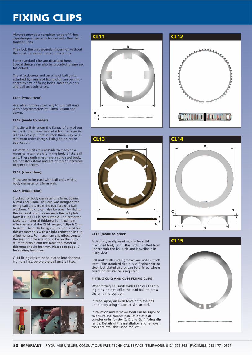
IMPORTANT - IF YOU ARE UNSURE, CONSULT OUR FREE TECHNICAL SERVICE. TELEPHONE: 0121 772 8481 FACSIMILE: 0121 771 032730
FIXING CLIPS
Alwayse provide a complete range of fixingclips designed specially for use with their balltransfer units.
They lock the unit securely in position withoutthe need for special tools or machinery.
Some standard clips are described here.Special designs can also be provided, please askfor details.
The effectiveness and security of ball unitsattached by means of fixing clips can be influ-enced by size of fixing holes, table thicknessand ball unit tolerances.
CL11 (stock item)
Available in three sizes only to suit ball unitswith body diameters of 36mm, 45mm and62mm.
CL12 (made to order)
This clip will fit under the flange of any of ourball units that have parallel sides. If any partic-ular size of clip is not in stock there may be aminimum order charge. Fixing hole sizes onapplication.
On certain units it is possible to machine arecess to retain the clip in the body of the ballunit. These units must have a solid steel body,are not stock items and are only manufacturedto specific orders.
CL13 (stock item)
These are to be used with ball units with abody diameter of 24mm only.
CL14 (stock item)
Stocked for body diameter of 24mm, 36mm,45mm and 62mm. This clip was designed forfixing ball units from the top face of a ballplatform. The clip can also be used for fixingthe ball unit from underneath the ball plat-form if clip CL11 is not suitable. The preferredtable top material thickness for maximumeffectiveness of the CL14 range of clips is 2mmto 4mm. The CL14 fixing clips can be used forthicker materials with a slight reduction in clipeffectiveness. For maximum clip effectivenessthe seating hole size should be on the mini-mum tolerance and the table top materialthickness should be 4mm. Please see page 17for seating hole sizes
CL14 fixing clips must be placed into the seat-ing hole first, before the ball unit is fitted.
CL13
CL15
CL14
CL11 CL12
CL15 (made to order)
A circlip type clip used mainly for solidmachined body units. The circlip is fitted fromunderneath the ball unit and is available inmany sizes.
Ball units with circlip grooves are not ex stockitems. The standard circlip is self colour springsteel, but plated circlips can be offered wherecorrosion resistance is required.
FITTING CL12 AND CL14 FIXING CLIPS
When fitting ball units with CL12 or CL14 fix-ing clips, do not strike the load ball to pressthe unit into position.
Instead, apply an even force onto the ballunit’s body using a tube or similar tool.
Installation and removal tools can be suppliedto ensure the correct installation of balltransfer units for the CL12 and CL14 fixing cliprange. Details of the installation and removaltools are available upon request.
B
D
A
B
A
C
A
B
C D

FIX
ING
CLIP
S
31INTERNATIONAL TEL: 44 121 772 8481 INTERNATIONAL FAX: 44 121 771 0327 [email protected] www.alwayse.co.uk
To order, specify REF Nº i.e. CL11-22.For CL12 and CL15 clips specify REF Nº and ball unit REF Nº i.e. CL12,1007.
CL11
CL12
REF No
CL13
CL14
CL15
Flange diameter Inside diameter Material ThicknessRef No. A B D
CL11-22 ∅71.1 ∅35.9 0.7CL11-30 ∅71.1 ∅44.9 0.7CL11-45 ∅72.6 ∅61.2 0.7
CL11 CLIP TO BE USED WITH THE FOLLOWING BALL UNITSCL11-22 CL11-30 CL11-45
522-0, 522-4 and 522-6 530-0, 530-4 and 530-6 545-0, 545-4 and 545-6(pages 16 & 17) (pages 16 & 17) (pages 16 & 17)
800-22 and 810-22 800-30, 805-30 800-45, 80545 and806-30, 807-30 and 810-30 810-45
(pages 18 & 19) (pages 18 & 19) (pages 18 & 19)
CL12 CLIP TO BE USED WITH THE FOLLOWING BALL UNITS
1007 515-0, 515-4, 515-6 6025-2 and 6025-4 7104, 7124522-0, 522-4, 522-6 7125, 7152530-0, 530-4, 530-6 and 7171545-0, 545-4, 545-6
(Pages 8 & 9) (Pages 16 & 17) (Pages 20 & 21) (Pages 22 & 23)
0519-22, 3019-22 810-15, 800-22 3010, 3011, 10171019-22, 1029-22 810-22, 800-30 1018, 1509,1507
and 2019-22 805-30, 810-30 1027, 1028, 2009800-45, 805-45 2010, 4007 and806-30, 807-30 4008
810-45 and 800-60(Pages 28 & 29) (Pages 18 & 19) (Pages 26 & 27)
Flange diameter Inside diameter LengthRef No. A B C
CL13-15 ∅41.4 ∅23.4 3.2
The CL13-15 fixing clip can be used with the 515-0. 515-4 and 515-6ball units (pages 16-17) and also the 810-15 ball unit (pages 18 and 19).
Flange Body outside Length Materialdiameter diameter Thickness
Ref No. A B C D
CL14-15 ∅30.9 ∅24.7 6.0 0.3CL14-22 ∅44.5 ∅36.7 7.0 0.3CL14-30 ∅54.9 ∅45.7 7.0 0.3CL14-45 ∅74.0 ∅62.7 7.0 0.3
CL14 CLIP TO BE USED WITH THE FOLLOWING BALL UNITS
CL14-15 CL14-22 CL14-30 CL14-45515-0, 515-4 and 522-0, 522-4 and 530-0, 530-4 and 545-0, 545-4 and
515-6 522-6 530-6 545-6(pages 16 & 17) (pages 16 & 17) (pages 16 & 17) (pages 16 & 17)
7104 800-22, 810-22 800-30, 805-30, 806-30 800-45, 805-45(pages 22 & 23) (pages 18 & 19) 807-30 and 810-30 and 810-45
810-15 (pages 18 & 19) (pages 18 & 19)(pages 18 & 19) 1017, 1018, 1507
and 1509(pages 26 & 27)
7124(pages 22 & 23)
CL15 CLIP TO BE USED WITH THE FOLLOWING BALL UNITS1004 7104, 7124, 7125 0519-22, 3019-22, 1019-22
7152 and 7171 1029-22 and 2019-22(pages 8 & 9) (pages 22 & 23) (pages 28 & 29)
810-15, 800-22, 810-22 3010, 3011, 1017, 1018800-30, 805-30, 810-30 1509, 1507, 1027, 1028800-45, 805-45, 810-45 2009, 2010, 4007
and 800-60 and 4008(pages 18 and 19) (pages 26 and 27)
CL12 fixing clip sizes available upon request
Please see page 17 for seating hole sizes
Ball units with circlip grooves are available on requestCL15 fixing clip sizes available upon request

IMPORTANT - IF YOU ARE UNSURE, CONSULT OUR FREE TECHNICAL SERVICE. TELEPHONE: 0121 772 8481 FACSIMILE: 0121 771 032732
TEE BLOCKS, DIE TABLES
TEE BLOCKS
Single Minute Tool and DieChanging
Our comprehensive range of tee blocksand spring loaded ball transfer units, setinto the bed of your power press ormachine tool, will allow effortless posi-tioning of tooling but still allow rigidclamping.
We supply tee blocks for both standardand non-standard tee slots the length,pitch, ball height etc. being dependanton tool weight and profile.
Other sizes available on request.
QUICK CHANGE DIE TABLES
For all types of moulding and stampingapplications.
They allow quick, easy tool changingwith storage close to the machine.All tables are fully guarded. Access tothe machine via a lift-up gate ifrequired.
Custom designed to your specificrequirements, installation is carried outby our engineers.
NOTE - safety rails should be fittedwhere there is the possibility of loadsrolling off.
a b c h22 37 16 38
24 42 18 42
28 46 20 48
36 56 25 61
Standard Tee Block Slot Proportions
Tee blocks can be designed and manufactured to suit particular applications.See pages 24 & 25 for our range of Die Lifter ball units.
TEE BLOCKS
DIN 650
QUICK CHANGE DIE TABLES
a
c
b
h
LOADUNCLAMPED
LOADCLAMPED
TEE BLOCK SECUREDBY SOCKET SCREW