Embed Size (px)
Citation preview
W0019 1
Baldor•Dodge Bearing Fault Frequencies, What They Mean and How to
Utilize Them
C.O. Engineer - Bearings and PT Components
09/04/2007
Preventative maintenance is a growing trend in industrial operations. One critical area of preventative
maintenance includes vibration monitoring. A high quality vibration monitoring program will analyze and trend many
areas of an operating machine. Typically, the most critical area for analysis is directed at the bearings. Many questions
often surface regarding bearing fault frequencies and how they relate to our bearings. The following FAQs should
cover many of the common questions encountered.
What is a bearing fault frequency?
Bearing fault frequencies, sometimes called defect frequencies, are simply harmonics that coincide with
recurring and consistent impacts between two bearing surfaces. The harmonic is simply a rotational speed or order as
a relation to the prime rotating body. If bearing surfaces are smooth then there are no amplitudes from the energy loss
of a collision. However, as a bearing begins to fatigue or fail then imperfections on contacting surfaces create collisions
which result in an amplitude emission of energy. This collision will occur consistently in proportion to the frequency
of the primary mover.
The frequency allows the user to identify the component that most contributes to uneven operation. If
component frequencies are known then the user can look for amplitudes across the vibration spectrum that align with
component frequencies. The user can determine the source of the problem once the disrupting harmonic is matched to
the predicted component frequency.
What constitutes a defect?
From a vibration standpoint, any area of the bearing contacting surfaces that are not smooth, stiff or stable
can emit energy losses in a measurable form. A fault is most often degradation of the bearing raceways from fatigue.
The fatigue will first arrive in the form of small pits on the surface of the steel. These pits will gradually propagate
into larger surface areas known as spalling. Other forms of faults include true bearing manufacturer’s defects, poor
steel quality, excessive looseness, and effects from contamination.
How are the frequencies determined?
Bearing fault frequencies are determined by the geometry of the bearing, the number of rolling elements, the
type of bearing, and the type of rotation (inner or outer ring) are a function of the bearing rotational speed.
Baldor•Dodge provides fault frequencies for our bearings in the Engineering section of every Baldor•Dodge catalog.
We provide source equations in that section for convenience as well.
What do the fault frequencies mean?
There are four main types of vibration frequencies that relate to the different components of the bearing.
They include the ball pass frequencies of the inner and outer ring, the fundamental train frequency and the ball/roller
spin frequency.
Inner Ring – This is commonly referred to as ‘Ball Pass Frequency of the Inner Race’ (BPFI) and
is the frequency at which the balls or rollers will pass over or contact a single point on the inner race
of the bearing. Another way to understand this is the number of times a roller will contact a point
on the inner ring in one revolution of the inner ring. For example, a 208 Baldor•Dodge ball bearing
has a BPFI of 5.443. This means that 5.443 balls will contact a single point on the raceway in one
revolution of the inner ring.

W0019 2
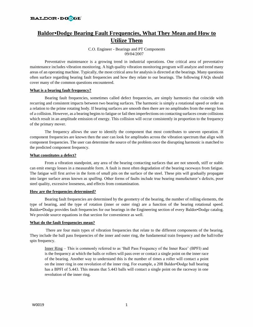
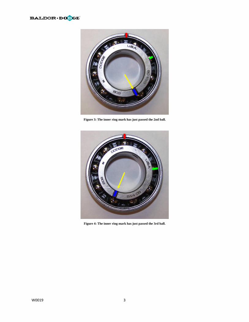
The following images will illustrate the relationship of roller and inner ring raceway contact for one rotation
of the inner ring. Note for illustration purposes the red line indicates a stationary point on the outer ring, the green
represents rotational alignment of the initial contacting roller and the blue will illustrate a match mark of the inner
ring. The bearing was initially marked but the marks didn’t show up well in the image.
Figure 1: Starting points indicated for example.
Figure 2: By rotating the inner ring, this illustrates the point of at which
the blue inner ring match mark passes the first ball.
W0019 3
Figure 3: The inner ring mark has just passed the 2nd ball.
Figure 4: The inner ring mark has just passed the 3rd ball.
W0019 4
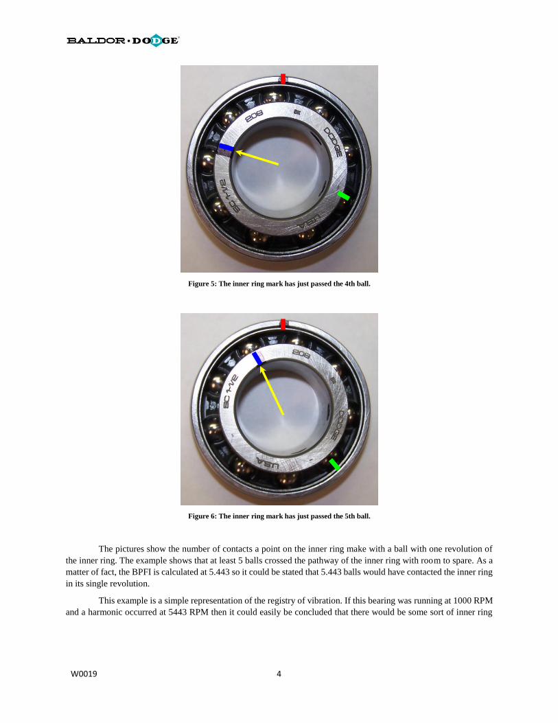
Figure 5: The inner ring mark has just passed the 4th ball.
Figure 6: The inner ring mark has just passed the 5th ball.
The pictures show the number of contacts a point on the inner ring make with a ball with one revolution of
the inner ring. The example shows that at least 5 balls crossed the pathway of the inner ring with room to spare. As a
matter of fact, the BPFI is calculated at 5.443 so it could be stated that 5.443 balls would have contacted the inner ring
in its single revolution.
This example is a simple representation of the registry of vibration. If this bearing was running at 1000 RPM
and a harmonic occurred at 5443 RPM then it could easily be concluded that there would be some sort of inner ring
W0019 5
raceway defect. As a matter of fact in 1000 revolutions of that inner ring, 5443 balls have contacted that raceway
defect.
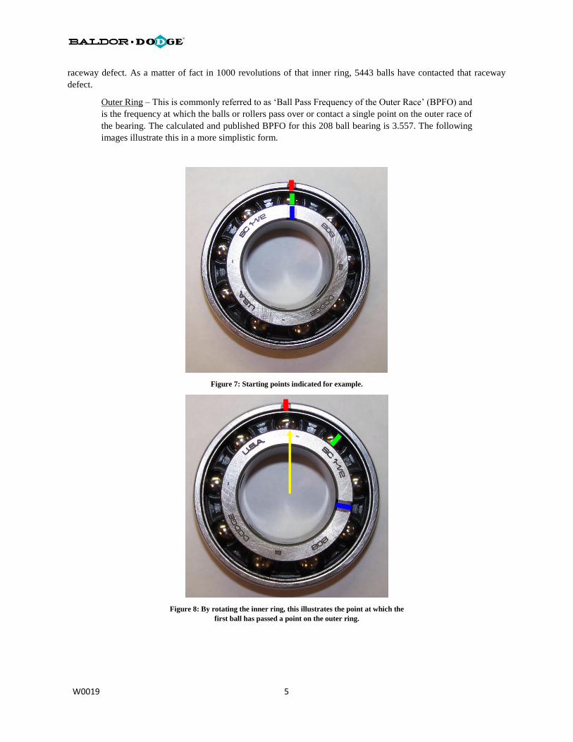
Outer Ring – This is commonly referred to as ‘Ball Pass Frequency of the Outer Race’ (BPFO) and
is the frequency at which the balls or rollers pass over or contact a single point on the outer race of
the bearing. The calculated and published BPFO for this 208 ball bearing is 3.557. The following
images illustrate this in a more simplistic form.
Figure 7: Starting points indicated for example.
Figure 8: By rotating the inner ring, this illustrates the point at which the
first ball has passed a point on the outer ring.

W0019 6
Figure 9: Continuing with the inner ring rotation. This is the point at
which the second roller crosses the stationary point on the outer ring.
Figure 10: The third roller has now crossed the stationary point on the
outer ring.
W0019 7
Again, with a single rotation of the inner ring at least 3 balls have passed a single given point on the outer
ring. As a matter of fact, 3.557 balls would pass a single point of the outer ring in one full rotation. If a defect was
present on the raceway of the outer ring, the vibration spectrum would show a peak harmonic of 3557 RPM for this
bearing at 1000 RPM.
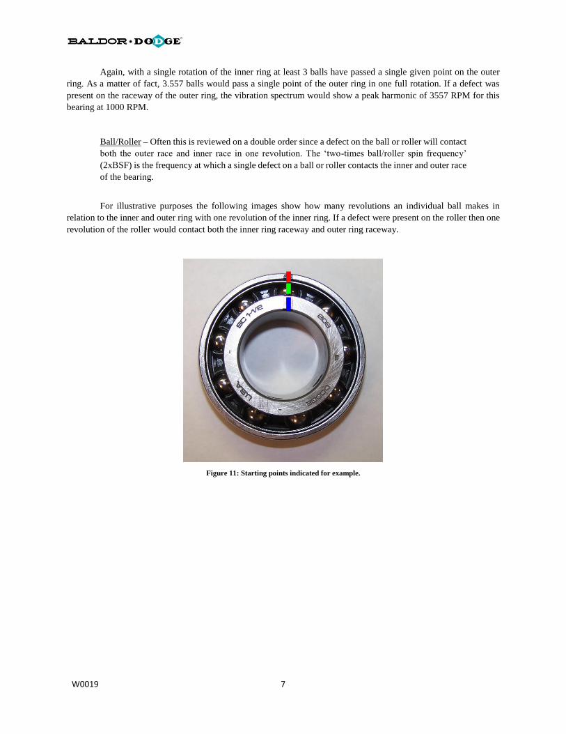
Ball/Roller – Often this is reviewed on a double order since a defect on the ball or roller will contact
both the outer race and inner race in one revolution. The ‘two-times ball/roller spin frequency’
(2xBSF) is the frequency at which a single defect on a ball or roller contacts the inner and outer race
of the bearing.
For illustrative purposes the following images show how many revolutions an individual ball makes in
relation to the inner and outer ring with one revolution of the inner ring. If a defect were present on the roller then one
revolution of the roller would contact both the inner ring raceway and outer ring raceway.
Figure 11: Starting points indicated for example.
W0019 8
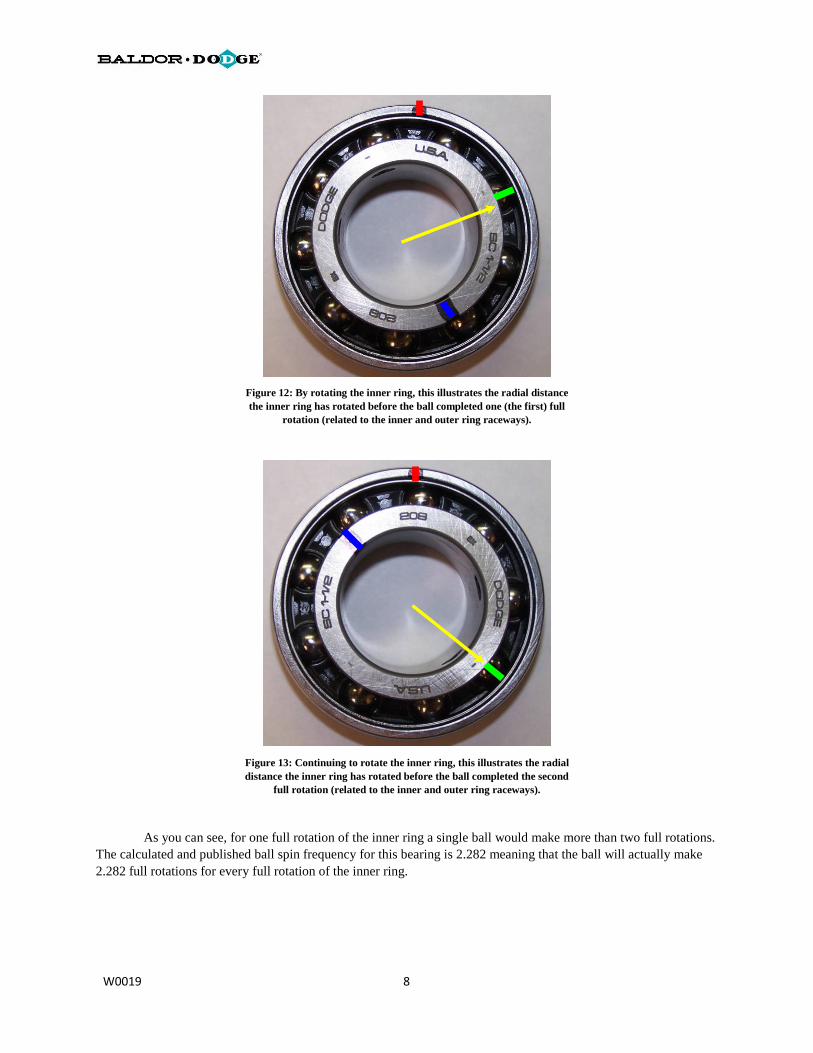
Figure 12: By rotating the inner ring, this illustrates the radial distance
the inner ring has rotated before the ball completed one (the first) full
rotation (related to the inner and outer ring raceways).
Figure 13: Continuing to rotate the inner ring, this illustrates the radial
distance the inner ring has rotated before the ball completed the second
full rotation (related to the inner and outer ring raceways).
As you can see, for one full rotation of the inner ring a single ball would make more than two full rotations.
The calculated and published ball spin frequency for this bearing is 2.282 meaning that the ball will actually make
2.282 full rotations for every full rotation of the inner ring.
W0019 9
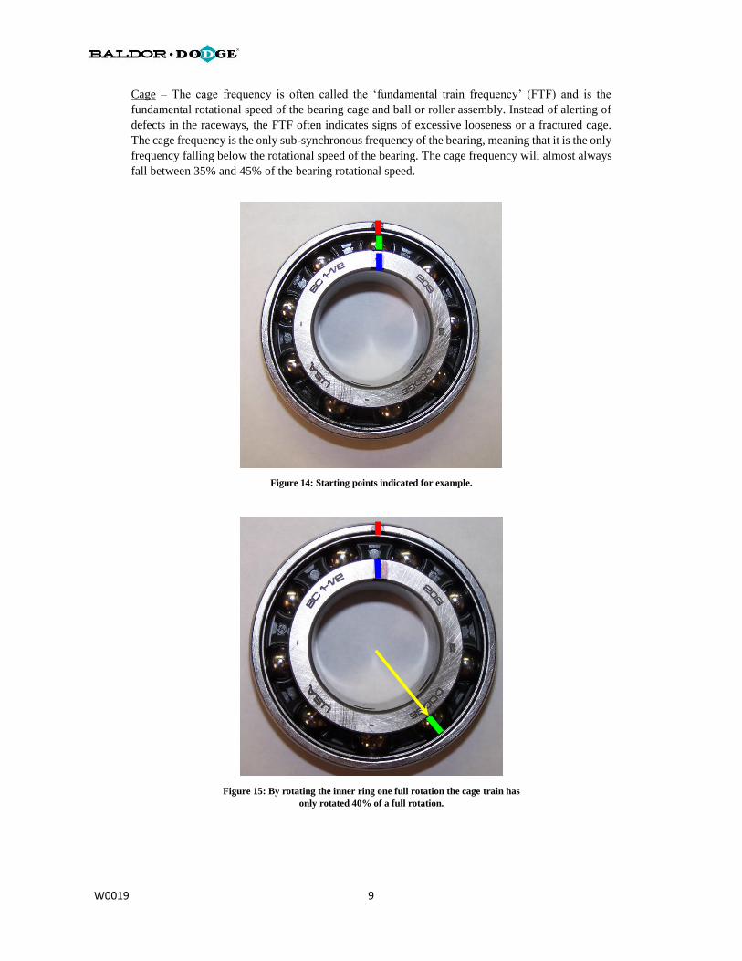
Cage – The cage frequency is often called the ‘fundamental train frequency’ (FTF) and is the
fundamental rotational speed of the bearing cage and ball or roller assembly. Instead of alerting of
defects in the raceways, the FTF often indicates signs of excessive looseness or a fractured cage.
The cage frequency is the only sub-synchronous frequency of the bearing, meaning that it is the only
frequency falling below the rotational speed of the bearing. The cage frequency will almost always
fall between 35% and 45% of the bearing rotational speed.
Figure 14: Starting points indicated for example.
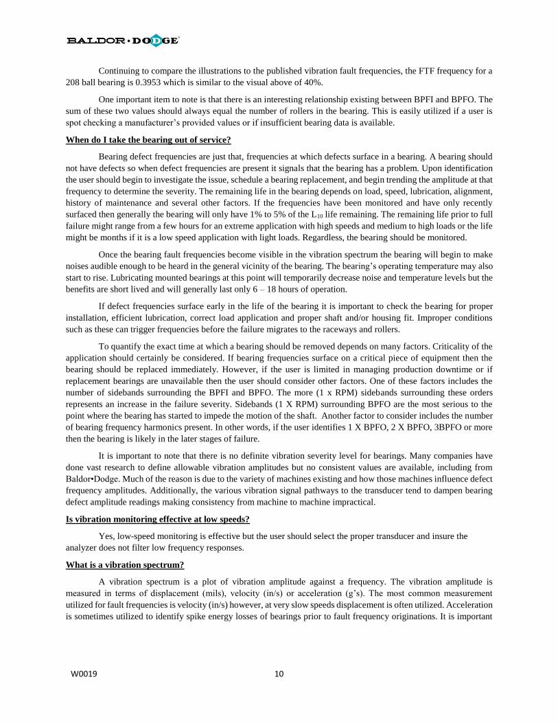
Figure 15: By rotating the inner ring one full rotation the cage train has
only rotated 40% of a full rotation.
W0019 10
Continuing to compare the illustrations to the published vibration fault frequencies, the FTF frequency for a
208 ball bearing is 0.3953 which is similar to the visual above of 40%.
One important item to note is that there is an interesting relationship existing between BPFI and BPFO. The
sum of these two values should always equal the number of rollers in the bearing. This is easily utilized if a user is
spot checking a manufacturer’s provided values or if insufficient bearing data is available.
When do I take the bearing out of service?
Bearing defect frequencies are just that, frequencies at which defects surface in a bearing. A bearing should
not have defects so when defect frequencies are present it signals that the bearing has a problem. Upon identification
the user should begin to investigate the issue, schedule a bearing replacement, and begin trending the amplitude at that
frequency to determine the severity. The remaining life in the bearing depends on load, speed, lubrication, alignment,
history of maintenance and several other factors. If the frequencies have been monitored and have only recently
surfaced then generally the bearing will only have 1% to 5% of the L10 life remaining. The remaining life prior to full
failure might range from a few hours for an extreme application with high speeds and medium to high loads or the life
might be months if it is a low speed application with light loads. Regardless, the bearing should be monitored.
Once the bearing fault frequencies become visible in the vibration spectrum the bearing will begin to make
noises audible enough to be heard in the general vicinity of the bearing. The bearing’s operating temperature may also
start to rise. Lubricating mounted bearings at this point will temporarily decrease noise and temperature levels but the
benefits are short lived and will generally last only 6 – 18 hours of operation.
If defect frequencies surface early in the life of the bearing it is important to check the bearing for proper
installation, efficient lubrication, correct load application and proper shaft and/or housing fit. Improper conditions
such as these can trigger frequencies before the failure migrates to the raceways and rollers.
To quantify the exact time at which a bearing should be removed depends on many factors. Criticality of the
application should certainly be considered. If bearing frequencies surface on a critical piece of equipment then the
bearing should be replaced immediately. However, if the user is limited in managing production downtime or if
replacement bearings are unavailable then the user should consider other factors. One of these factors includes the
number of sidebands surrounding the BPFI and BPFO. The more (1 x RPM) sidebands surrounding these orders
represents an increase in the failure severity. Sidebands (1 X RPM) surrounding BPFO are the most serious to the
point where the bearing has started to impede the motion of the shaft. Another factor to consider includes the number
of bearing frequency harmonics present. In other words, if the user identifies 1 X BPFO, 2 X BPFO, 3BPFO or more
then the bearing is likely in the later stages of failure.
It is important to note that there is no definite vibration severity level for bearings. Many companies have
done vast research to define allowable vibration amplitudes but no consistent values are available, including from
Baldor•Dodge. Much of the reason is due to the variety of machines existing and how those machines influence defect
frequency amplitudes. Additionally, the various vibration signal pathways to the transducer tend to dampen bearing
defect amplitude readings making consistency from machine to machine impractical.
Is vibration monitoring effective at low speeds?
Yes, low-speed monitoring is effective but the user should select the proper transducer and insure the
analyzer does not filter low frequency responses.
What is a vibration spectrum?
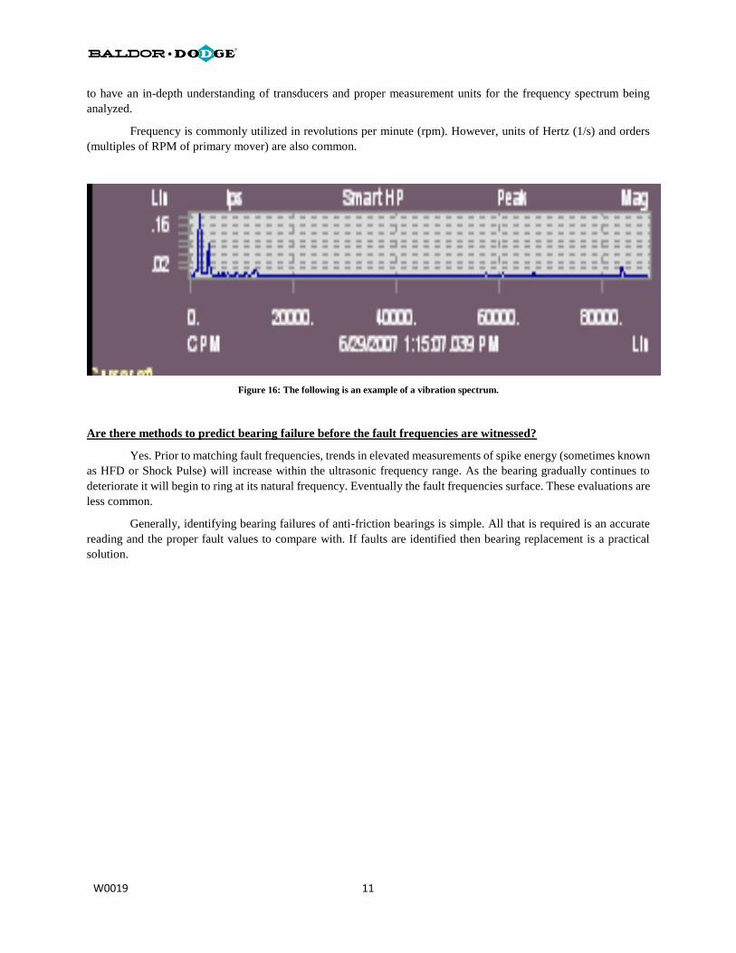
A vibration spectrum is a plot of vibration amplitude against a frequency. The vibration amplitude is
measured in terms of displacement (mils), velocity (in/s) or acceleration (g’s). The most common measurement
utilized for fault frequencies is velocity (in/s) however, at very slow speeds displacement is often utilized. Acceleration
is sometimes utilized to identify spike energy losses of bearings prior to fault frequency originations. It is important
W0019 11
to have an in-depth understanding of transducers and proper measurement units for the frequency spectrum being
analyzed.
Frequency is commonly utilized in revolutions per minute (rpm). However, units of Hertz (1/s) and orders
(multiples of RPM of primary mover) are also common.
Figure 16: The following is an example of a vibration spectrum.
Are there methods to predict bearing failure before the fault frequencies are witnessed?
Yes. Prior to matching fault frequencies, trends in elevated measurements of spike energy (sometimes known
as HFD or Shock Pulse) will increase within the ultrasonic frequency range. As the bearing gradually continues to
deteriorate it will begin to ring at its natural frequency. Eventually the fault frequencies surface. These evaluations are
less common.
Generally, identifying bearing failures of anti-friction bearings is simple. All that is required is an accurate
reading and the proper fault values to compare with. If faults are identified then bearing replacement is a practical
solution.