Embed Size (px)
Citation preview

Balancing High Strength Tubing Selection and
Cost in Hydraulic System Design
IFPE 2014- Fluid Power Seminar Series
Las Vegas, NV
March 5, 2014
John Wilbanks
Quality Manager
Plymouth Tube Company

1
ABSTRACT
The automotive industry has fueled many advances in high strength steel materials as we know them
today. Vehicle body panels and structural components have benefited significantly from decades of
development targeted at improving vehicle occupant safety and reducing overall vehicle weight for
enhanced fuel economy. At the same time, ferrous and non-ferrous tubing options for hydraulic
system design have changed little. While this has served to simplify and standardize design
practices, the trend toward higher hydraulic system pressures and improved system efficiency has
created difficulties for the designer in material selection. Hydraulic system engineers seeking ferrous
or non-ferrous tubing options capable of meeting the demands of today’s higher pressure systems are
often faced with limited choices and very real cost constraints. This writing will present a brief
history of high strength steel development, explore current high-strength tubing options and their
impact on system design, and investigate new developments in high strength hydraulic tubing that
give the designer more cost-effective alternatives to meet overall system design objectives.
High Strength Steel Development
Since the 1960’s the automotive industry has been one of the primary drivers in the development of high
strength steels as the need arose to improve vehicle fuel economy and increase occupant safety. Initial
efforts began with development of now familiar High Strength Low Alloy (HSLA) steels and accelerated
in the 1990’s through the efforts of the Ultra-Light Steel Auto Body (ULSAB) consortium. Collaborative
work done under the umbrella of ULSAB led to more exotic specialized steels specifically tailored to
automotive industry needs. The chart in Figure 1 below is often referred to as the classic “banana chart”
and plots the relative tensile strength in megapascals (MPa) and elongation for various categories and
grades of steels. It also visually demonstrates the typical inverse relationship between tensile strength and
ductility. The left-most region of the chart in Figure 1 includes Low Strength Steels (LSS, < 270 MPa
tensile strength) which are generally made up of low carbon mild steels, bake hardened steels, interstitial
free steels, and other similar grades. LSS have exceptional ductility, as indicated by their high observed
elongation values, and lend themselves well to forming and bending. The middle region of the chart
Figure 1 - Relative Tensile Strength and Elongation for LS, HSS, and UHSS grade steels, Source: worldautosteel.org1
0 200 400 600 800 1,000 1,200 1,4000
10
20
30
40
50
60
IF
MILDIS
CMn
BH
HSLA
IF-HS
DP-CPMART
1,600
Tensile Strength (MPa)
High Strength
Steels (HSS)
Ultra High Strength Steels (UHSS)
(>700MPa)Low Strength
Steels (<270MPa)70
Next Generation
AHSS
Tota
l Elo
nga
tio
n (%
)

2
includes various High Strength Steel (HSS) grades having tensile strengths between 270MPa and
700MPa. HSS include Carbon Manganese (CMn) and various High Strength Low Alloy (HSLA) grades
that achieve higher tensile strengths either with additional C and Mn content, the addition of various
micro-alloying elements, and/or manufacturing techniques that promote grain refinement and target
specific microstructures. In general, HSS grades are less ductile than LSS grades. Finally, the right-most
region of the chart includes Ultra High Strength steels (UHSS, > 700Mpa tensile strength). UHSS are
some of the strongest steels currently available with tensile strengths reaching to 1,600MPa and beyond.
UHSS typically exhibit the lowest ductility of any of the grades discussed in this writing.
Modern vehicle chassis designers have made good use of many grades and classes of steels as illustrated
in Figure 2 below. Materials are selected for their unique properties to achieve overall design objectives
for strength, cost minimization, impact resistance, and energy absorption. The end result is a vehicle with
less mass leading to improved fuel efficiency yet enhanced safety for occupants. Current research is
focused on next generation structural steels having additional ductility and strength, thus shifting the
curve both up and to the right.
Hydraulic Tubing Development
While advancements in steel chemistry and processing techniques have significantly improved the
mechanical properties of structural steels, relatively few of those advancements have impacted the
hydraulic tubing market. This is potentially due to several factors:
The hydraulic tubing industry requires tubing with significant ductility that can be easily cold
worked. The severity of cold work induced ranges from simple bends and flares to more complex
forms and shapes often found in tube end fittings.
Adding carbon to increase strength quickly reaches a point of diminishing returns as ductility is
degraded.
The majority of hydraulic tubing used today is Draw-Over-Mandrel (DOM) tubing. High
strength structural steels are often manufactured with specialized hot rolling processes that give
them their added strength and ductility in the as-rolled state. Steels produced by such processes
do not lend themselves well to the cold work and subsequent annealing required in the production
of DOM hydraulic tubing.
Figure 2 - Typical Structural Steel application in passenger
vehicle chassis design, Source: worldautosteel.org1
3
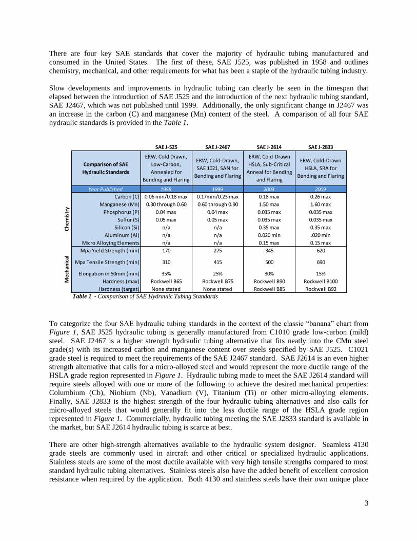
There are four key SAE standards that cover the majority of hydraulic tubing manufactured and
consumed in the United States. The first of these, SAE J525, was published in 1958 and outlines
chemistry, mechanical, and other requirements for what has been a staple of the hydraulic tubing industry.
Slow developments and improvements in hydraulic tubing can clearly be seen in the timespan that
elapsed between the introduction of SAE J525 and the introduction of the next hydraulic tubing standard,
SAE J2467, which was not published until 1999. Additionally, the only significant change in J2467 was
an increase in the carbon (C) and manganese (Mn) content of the steel. A comparison of all four SAE
hydraulic standards is provided in the Table 1.
To categorize the four SAE hydraulic tubing standards in the context of the classic “banana” chart from
Figure 1, SAE J525 hydraulic tubing is generally manufactured from C1010 grade low-carbon (mild)
steel. SAE J2467 is a higher strength hydraulic tubing alternative that fits neatly into the CMn steel
grade(s) with its increased carbon and manganese content over steels specified by SAE J525. C1021
grade steel is required to meet the requirements of the SAE J2467 standard. SAE J2614 is an even higher
strength alternative that calls for a micro-alloyed steel and would represent the more ductile range of the
HSLA grade region represented in Figure 1. Hydraulic tubing made to meet the SAE J2614 standard will
require steels alloyed with one or more of the following to achieve the desired mechanical properties:
Columbium (Cb), Niobium (Nb), Vanadium (V), Titanium (Ti) or other micro-alloying elements.
Finally, SAE J2833 is the highest strength of the four hydraulic tubing alternatives and also calls for
micro-alloyed steels that would generally fit into the less ductile range of the HSLA grade region
represented in Figure 1. Commercially, hydraulic tubing meeting the SAE J2833 standard is available in
the market, but SAE J2614 hydraulic tubing is scarce at best.
There are other high-strength alternatives available to the hydraulic system designer. Seamless 4130
grade steels are commonly used in aircraft and other critical or specialized hydraulic applications.
Stainless steels are some of the most ductile available with very high tensile strengths compared to most
standard hydraulic tubing alternatives. Stainless steels also have the added benefit of excellent corrosion
resistance when required by the application. Both 4130 and stainless steels have their own unique place
SAE J-525 SAE J-2467 SAE J-2614 SAE J-2833
Comparison of SAE
Hydraulic Standards
ERW, Cold Drawn,
Low-Carbon,
Annealed for
Bending and Flaring
ERW, Cold-Drawn,
SAE 1021, SAN for
Bending and Flaring
ERW, Cold-Drawn
HSLA, Sub-Critical
Anneal for Bending
and Flaring
ERW, Cold-Drawn
HSLA, SRA for
Bending and Flaring
Year Published 1958 1999 2003 2009
Carbon (C) 0.06 min/0.18 max 0.17min/0.23 max 0.18 max 0.26 max
Manganese (Mn) 0.30 through 0.60 0.60 through 0.90 1.50 max 1.60 max
Phosphorus (P) 0.04 max 0.04 max 0.035 max 0.035 max
Sulfur (S) 0.05 max 0.05 max 0.035 max 0.035 max
Silicon (Si) n/a n/a 0.35 max 0.35 max
Aluminum (Al) n/a n/a 0.020 min .020 min
Micro Alloying Elements n/a n/a 0.15 max 0.15 max
Mpa Yield Strength (min) 170 275 345 620
Mpa Tensile Strength (min) 310 415 500 690
Elongation in 50mm (min) 35% 25% 30% 15%
Hardness (max) Rockwell B65 Rockwell B75 Rockwell B90 Rockwell B100
Hardness (target) None stated None stated Rockwell B85 Rockwell B92
Table 1 - Comparison of SAE Hydraulic Tubing Standards
Ch
em
istr
yM
ech
anic
al

4
in the structural steel and hydraulic tubing market; however, the benefits they offer in the areas of
strength, ductility, and other unique properties, like corrosion resistance, are often offset by significantly
higher costs. Unless their specific mechanical or physical properties are needed, hydraulic system
designers will often select a lower-cost alternative.
The chart in Figure 3 is similar to the chart in Figure 1 and shows the relationship of various steel grades
to specific SAE hydraulic tubing specifications discussed above. Some grade regions have been
eliminated for clarity while 4130 and Austenitic Stainless steels have been added to show their
relationship. A region representing Plymouth Tube’s new HS-50 & HS-90 High Pressure Hydraulic
Tubing™ has also been added and will be discussed in more detail later. Note that HS-50™ meets the
chemistry and mechanical requirements of SAE J2614 while HS-90™ meets the requirements of SAE
J2833.
Hydraulic System Design Using High Strength Steels
Hydraulic system design is a straightforward science. System designers use standard calculation methods
and select materials that achieve the most efficient and cost effective balance among the following
criteria:
Meet system design pressure minimums
Minimize pressure drop
Minimize heat generation
Reduce fluid turbulence
Eliminate cavitation on suction lines
Minimize system cost
Maximize overall system efficiency
Figure 3 - Typical Hydraulic Grade Steels and applicable SAE Standards
0 200 400 600 800 1,000 1,200 1,4000
10
20
30
40
50
60
HSLA
1,600
Tensile Strength (MPa)
High Strength Steels (HSS)
Ultra High Strength Steels (UHSS)
(>700MPa)Low Strength
Steels (<270MPa)70
AUSTENITIC
SS (3xx)
4130
CMn
MILD
Tota
l Elo
nga
tio
n (%
)
HS-50 & HS-90 High
Pressure Hydraulic

5
While this text is not intended to be a source for hydraulic system design, reviewing the process will help
show the importance of new, higher-strength tubing developments and how they benefit the designer.
Step 1: Determine Required Flow Diameter
Table 2 (above) gives a few examples of Recommended Flow Diameters for required flow rates based on
the following recommended flow velocities:
Pressure Lines – 25 ft/sec (7.62m/sec)
Return Lines – 10 ft/sec (3.05m/sec)
Suction Lines – 4 ft/sec (1.22m/sec)
For design velocities that differ from those given in standard tables, the designer can calculate the
appropriate tube Inside Diameter (ID) using one of the following formulas based on the units desired.
To calculate Tube ID (d) in inches:
𝑑 = 0.64√𝐹𝑙𝑜𝑤 𝑖𝑛 𝐺𝑃𝑀
𝑉𝑒𝑙𝑜𝑐𝑖𝑡𝑦 𝑖𝑛 𝑓𝑡/𝑠𝑒𝑐
To calculate Tube I.D. (d) in millimeters:
𝑑 = 4.61√𝐹𝑙𝑜𝑤 𝑖𝑛 𝑙𝑝𝑚
𝑉𝑒𝑙𝑜𝑐𝑖𝑡𝑦 𝑖𝑛 𝑚/𝑠𝑒𝑐
Step 2: Determine Tube OD and Wall
Pressure rating tables are available that allow the designer to quickly determine the tube diameter and
wall thickness combination that satisfies system operating pressure and flow requirements. Design
pressures for selected wall diameters for 0.500” Outer Diameter (OD) tubing are provided in Table 3 for
Table 2 - Recommended Flow Diameter2
Pre
ssu
re L
ine
s
Re
turn
Lin
es
Suct
ion
Lin
es
Pre
ssu
re L
ine
s
Re
turn
Lin
es
Suct
ion
Lin
es
5.00 0.286 0.452 0.716 13.00 0.462 0.728 1.154
5.50 0.300 0.474 0.750 14.00 0.479 0.756 1.197
6.00 0.314 0.495 0.784 15.00 0.496 0.782 1.239
6.50 0.326 0.515 0.816 16.00 0.512 0.808 1.280
7.00 0.339 0.534 0.847 17.00 0.528 0.833 1.319
7.50 0.351 0.553 0.876 18.00 0.543 0.857 1.368
8.00 0.362 0.571 0.905 19.00 0.558 0.880 1.395
8.50 0.373 0.589 0.933 20.00 0.572 0.903 1.431
9.00 0.384 0.606 0.960 22.00 0.600 0.947 1.501
9.50 0.395 0.623 0.986 24.00 0.627 0.990 1.568
10.00 0.405 0.639 1.012 26.00 0.653 1.030 1.632
11.00 0.425 0.670 1.061 28.00 0.677 1.069 1.693
12.00 0.433 0.700 1.109 30.00 0.701 1.143 1.753
Max
imu
m f
low
rate
, gp
m
Recommended flow diameter,
in.
Max
imu
m f
low
rate
, gp
m
Recommended flow diameter,
in.

6
later discussion. If severity of service ratings other than “A” (normal) are utilized apply the appropriate
derating factor to the values prior to selecting OD and Wall. Other known considerations for the system
designer include temperature derating factors and tube D/T ratio in bending applications (again, the
specific details of various service and temperature derating, etc. are not covered in this text, but readily
available and known to the system designer).
Designers may also apply Lame’s equation to determine appropriate OD and Wall thickness values
required to meet system design pressure requirements.
Lame’s equation follows:
𝑃 = 𝑆 (𝐷2 − 𝑑2
𝐷2 + 𝑑2)
Where:
D = Tube OD (in)
d = Tube ID (in), or D-2T
P = Recommended design pressure (psi)
S = Allowable stress for design factor of 4, (psi)
T = Tube wall thickness (in)
For thin walled tubes (D/T ≥ 10) the designer can substitute Barlow’s formula: P = 2ST/D
Design Stress Values
The key variable in selecting tubing that satisfies system pressure requirements is the allowable design
stress of the tube material itself. For general applications not requiring special corrosion resistance or high
strength, C1010 steel has been the industry standard for decades.
Table 3 - Design Burst Pressure2
Ste
el 1
01
0 (
SAE
J52
4 a
nd
J52
5)
Ste
el 1
02
1 (
SAE
J24
67
)
Stai
nle
ss S
tee
l (3
04
, 31
6)
41
30
, HSL
A, P
lym
ou
th H
S-
50
Hyd
rau
lic
Co
pp
er
0.500 0.049 0.402 2,700 3,250 4,050 1,300
0.500 0.058 0.384 3,250 3,900 4,850 1,550
0.500 0.065 0.370 3,650 4,400 5,500 1,750
0.500 0.072 0.356 4,100 4,900 6,150 1,950
0.500 0.083 0.334 4,800 5,750 7,200 2,300
0.500 0.095 0.310 5,550 6,650 8,350 2,650
0.500 0.109 0.282 6,450 7,750 9,750 3,100
0.500 0.120 0.260 7,200 8,650 10,800 3,450
Tub
e ID
, in
.
Design pressure, psi
(4:1 design factor)
Tub
e O
D, i
n.
Wal
l th
ickn
ess
, in
.

7
A highly formable and bendable steel tubing, C1010 offers flexibility in meeting low-pressure design
needs for fabricated port-to-port hard lines and hose end fittings at a minimal cost. Table 4 (shown on
Page 8) gives a side-by-side comparison of Allowable Design Stress Ratings for various material types.
From Table 4 the designer can clearly see that HSLA steels, which include HS-50 High Pressure
Hydraulic™, 304 and 316 Stainless Steel, and 4130 all offer a significant advantage in allowable design
stress over standard C-1010 steel. At a design factor of 4, this advantage amounts to a 50% increase in
allowable design stress. To illustrate some of the potential benefits to the designer we turn to the
following example.
Example 1
Our designer is looking at a hydraulic pressure line application that might normally use 0.500” OD x
0.083” Wall C1010 tubing at a design pressure of 4,800 psi (Table 3) and a flow of approximately 7 gpm
(Table 2). In this case however, the system must operate at a target design pressure of 7,200 psi. Looking
at Table 3, our designer sees that he has at least two options:
1) Increase the wall thickness of the tube to 0.120”.
2) Use a higher strength material, like HS-50 High Pressure Hydraulic, with the original 0.500” x
0.083” tube dimensions.
The first option meets the design pressure constraint but requires such a heavy wall that the ID is reduced
to only 0.260”. This restricts flow volume to only 4.0 gpm (a 40% decrease) and could lead to other
problems:
Increased flow turbulence
Increased pressure drop
Increased heat generation
Increased system weight (a 32% increase)
Difficulty bending and forming
Potential routing issues due to necessity of increasing minimum bend radii
Cost impact of purchasing new tooling for bending/forming applications, etc.
The second option, substituting HS-50 High Pressure Hydraulic, also meets the design pressure
constraint, but without the negative impact on flow diameter and other factors. The one impact that must
be considered is whether the price premium of the higher strength material offsets these negative impacts.
Example 2
Our designer is looking at a similar hydraulic pressure line application that might normally use a
0.500” OD x 0.083” Wall C1010 tube. In this example the required design pressure is 4,800 psi and the
designer wishes to improve flow to a minimum of 8.5 gpm.
Looking at Table 3, our designer sees that the 0.500” x 0.083” C1010 tube meets the 4,800 psi design
pressure requirement with a tube ID of 0.334”. This tube ID corresponds to a flow of approximately 7
gpm (Table 2). Looking again to Table 3, our designer also sees that he can reduce the tube wall to 0.058”
by selecting HS-50 High Pressure Hydraulic. This choice increases the tube ID to 0.384” with a flow
volume of 9 gpm, thus meeting the flow requirement for this application (a 28% increase in flow).
8
Negative impacts for this solution include slightly increased system cost and potential tooling costs.
These costs should be weighed against multiple positive impacts:
Improved flow (28% increase)
Reduced pressure drop
Reduced heat generation
Reduced system weight (26% reduction)
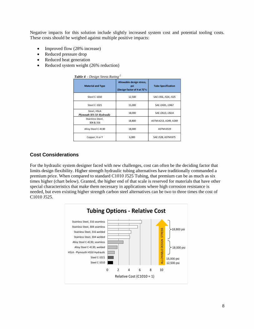
Cost Considerations
For the hydraulic system designer faced with new challenges, cost can often be the deciding factor that
limits design flexibility. Higher strength hydraulic tubing alternatives have traditionally commanded a
premium price. When compared to standard C1010 J525 Tubing, that premium can be as much as six
times higher (chart below). Granted, the higher end of that scale is reserved for materials that have other
special characteristics that make them necessary in applications where high corrosion resistance is
needed, but even existing higher strength carbon steel alternatives can be two to three times the cost of
C1010 J525.
Table 4 - Design Stress Rating2
Material and Type
Allowable design stress,
psi
(Design factor of 4 at 72°F)
Tube Specification
Steel C-1010 12,500 SAE J356, J524, J525
Steel C-1021 15,000 SAE J2435, J2467
Steel, HSLA
Plymouth HS-50 Hydraulic18,000 SAE J2613, J2614
Stainless Steel,
304 & 31618,800 ASTM A213, A249, A269
Alloy Steel C-4130 18,000 ASTM A519
Copper, K or Y 6,000 SAE J528, ASTM B75
0 2 4 6 8 10
Steel C-1010
Steel C-1021
HSLA - Plymouth HS50 Hydraulic
Alloy Steel C-4130, welded
Alloy Steel C-4130, seamless
Stainless Steel, 304 welded
Stainless Steel, 316 welded
Stainless Steel, 304 seamless
Stainless Steel, 316 seamless
Tubing Options - Relative Cost
AL
LO
WA
BL
ED
ES
IGN
ST
RE
SS
Relative Cost (C1010 = 1)
12,500 psi
15,000 psi
18,000 psi
18,800 psi

9
Elongation
MPa min psi min MPa min psi min % min
HS-50 High
Pressure Hydraulic345 50,025 500 72,500 30 SAE J2614
HS-90 High
Pressure Hydraulic620 89,900 690 100,050 15 SAE J2833
Yield Strength Tensile StrengthMECHANICAL
REQUIREMENTS
Applicable
Specification
HS-50 High Pressure Hydraulic Tubing offers the hydraulic system designer a cost-effective, high
strength alternative to C1010 J525 that matches the allowable design stress rating of 4130 (and is very
close to that of 304 and 316 stainless) at less than half the cost for like-sized tubing. In addition,
designers will find that they are able to utilize the higher strength of HS-50 High Pressure Hydraulic to
specify thinner walled tubing in standard applications allowing them to achieve higher flow rates and
lighter system weights with little or no cost premium. Looking back at an earlier example (Example 2),
our designer could switch from 0.500” x 0.083” C1010 SAE J525 to 0.500” x 0.058” HS-50 High
Pressure Hydraulic for less than a 5% increase in tubing cost, and have the added benefit of more flow
and less system weight.
Conclusion
HS-50 High Pressure Hydraulic was developed to meet specific and emerging needs of the hydraulic
tubing market at an attractive price. HS-50 High Pressure Hydraulic Tubing meets all chemical and
mechanical requirements of SAE J2614 and has been proven to provide cold forming and bending
characteristics similar to C-1010 SAE J525 tubing in various applications. Not only does HS-50 High
Pressure Hydraulic Tubing offer the system designer expanded alternatives for design that help maximize
system efficiency, there may be additional benefits in:
Elimination of machined components for applications where existing tubing strength limitations
create design problems.
The ability to stock a single grade hydraulic tube that can meet both low pressure and high
pressure system requirements, thus reducing inventory carrying costs and floor space
requirements.
HS-50 High Pressure Hydraulic Tubing is offered in wall thicknesses of 0.035” to 0.120” and in outer
diameters of 0.375” to 1.75” depending on OD-to-Wall ratio. Chemistry and mechanical requirements
are given below. HS-50 High Pressure Hydraulic is also available as a stress relieved product, HS-90
High Pressure Hydraulic. HS-90 is suitable for bending and flaring for hydraulic lines and meets the
requirements of SAE J2833.
CHEMICAL
COMPOSITION
C%
max
Mn%
max
S%
max
P%
max
Si%
max
Al%
max
Micro Alloying elements
(Ng, Cb, Ti, V)
max
HS-50 High
Pressure Hydraulic0.18 1.5 0.035 0.035 0.35 0.02 0.15
10
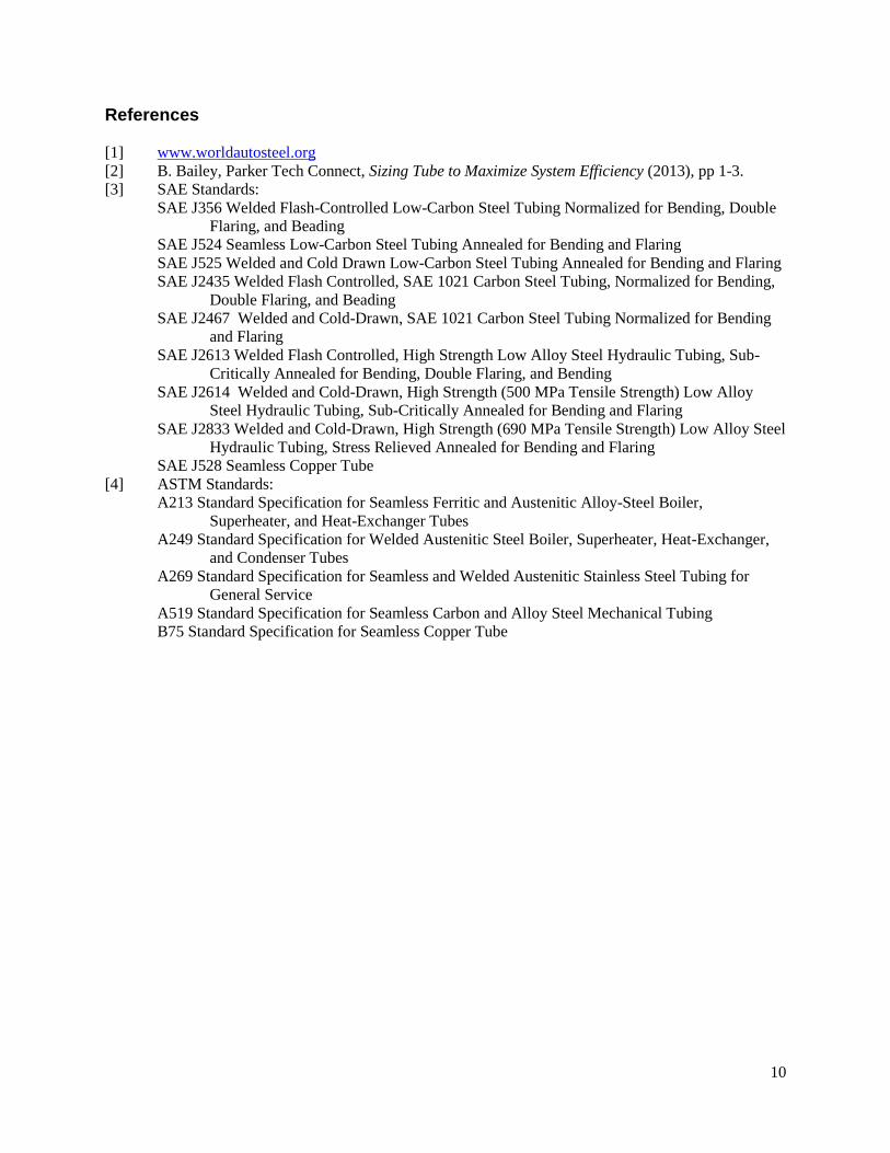
References
[1] www.worldautosteel.org
[2] B. Bailey, Parker Tech Connect, Sizing Tube to Maximize System Efficiency (2013), pp 1-3.
[3] SAE Standards:
SAE J356 Welded Flash-Controlled Low-Carbon Steel Tubing Normalized for Bending, Double
Flaring, and Beading
SAE J524 Seamless Low-Carbon Steel Tubing Annealed for Bending and Flaring
SAE J525 Welded and Cold Drawn Low-Carbon Steel Tubing Annealed for Bending and Flaring
SAE J2435 Welded Flash Controlled, SAE 1021 Carbon Steel Tubing, Normalized for Bending,
Double Flaring, and Beading
SAE J2467 Welded and Cold-Drawn, SAE 1021 Carbon Steel Tubing Normalized for Bending
and Flaring
SAE J2613 Welded Flash Controlled, High Strength Low Alloy Steel Hydraulic Tubing, Sub-
Critically Annealed for Bending, Double Flaring, and Bending
SAE J2614 Welded and Cold-Drawn, High Strength (500 MPa Tensile Strength) Low Alloy
Steel Hydraulic Tubing, Sub-Critically Annealed for Bending and Flaring
SAE J2833 Welded and Cold-Drawn, High Strength (690 MPa Tensile Strength) Low Alloy Steel
Hydraulic Tubing, Stress Relieved Annealed for Bending and Flaring
SAE J528 Seamless Copper Tube
[4] ASTM Standards:
A213 Standard Specification for Seamless Ferritic and Austenitic Alloy-Steel Boiler,
Superheater, and Heat-Exchanger Tubes
A249 Standard Specification for Welded Austenitic Steel Boiler, Superheater, Heat-Exchanger,
and Condenser Tubes
A269 Standard Specification for Seamless and Welded Austenitic Stainless Steel Tubing for
General Service
A519 Standard Specification for Seamless Carbon and Alloy Steel Mechanical Tubing
B75 Standard Specification for Seamless Copper Tube