Embed Size (px)
Citation preview

Feature: Balanced Filling in Thermoplastic Medical MoldingPage 18 Spring 2014
If molten plastic behaved like a simple fluid, there would be little need to worry about balanced filling during molding. The melt would fill the cavities like water, and the way the mold filled would have little or no influence on the properties of the molded parts. In reality, molten plastics are complex, viscous, and highly compressible fluids. How the mold fills can affect physical characteristics of the part such as size, strength, and appearance. Balanced filling can reduce part variations and improve part quality, both important in medical molding.
Multi-Cavity BalancingBalanced filling in plastic molding can refer to filling in multi-cavity molds or filling within a single part
cavity. Balanced filling in multi-cavity molds typically involves designing the runner system (hot or cold) so each cavity fills at the same time and at about the same temperature. When they fill at the same time and temperature, cavities tend to pack to the same density and are likely to shrink to the same size as the material solidifies.
In unbalanced multi-cavity molds, the ideal processing conditions for the early-filling cavities may be different than for late-filling cavities. The processing settings on the press end up being a compromise. This narrows the processing window and makes quality control more difficult. Cavities that fill first are more prone to flash and core deflection, while late filling cavities can exhibit non-fill and sink.
Two- and four-cavity molds tend to be naturally balanced. The distance from where the plastic enters the mold to the gates at each of the parts is the same. When the four-cavity layout is extended to eight cavities as in Figure A, an imbalance occurs. The runner distance to the outer four parts is longer than to the inner four parts. The flow simulation in Figure A shows the inner parts completely filled, while the outer parts still have the grey area yet to fill.
One solution is to use filling simulation to adjust the runner diameters to balance filling to all cavities. In Figure B, the diameters of the short runner segments feeding the inner four parts were reduced to restrict filling. When properly adjusted, all of the parts fill at about the same time.
This method of balancing runners, often called artificial balancing, has been used successfully for decades. It generates compact runner layouts (reducing regrind generation) and corrects many of the problems associated with unbalanced runners. Problems can occur when the restricted runners become too small to deliver adequate packing to the inner parts.
Artificially balanced runners are designed for a specific set of processing conditions. Changes to the filling speed or melt temperature can throw off the balance. Some molders attempt to balance flow by adjusting
Balanced Filling in Thermoplastic Medical Molding
By Mark YeagerPrincipal Engineer/Engineering ConsultantBayer MaterialScience LLC
SPE Injection Molding Division www.4spe.org

SPE Injection Molding Division www.4spe.org
Page 19 Spring 2014
the gate size. This is not recommended. Differences in gate sizes can lead to variations in packing, material shrinkage and part cosmetics. Gate balancing is also much more sensitive than runner balancing to changes in processing conditions.
An alternative eight-cavity runner option (Figure C) branches the runner segments to produce a geometrically balanced runner system. Because the flow distance to each cavity is the same, the parts should fill in a balanced fashion. In reality, runner systems that branch more than once usually fill the inner cavities ahead of the outer cavities.
The reason involves the way the hot shear layer in the runner segments splits at branching intersections. Dr. Beaumont of Beaumont Technologies, Inc. discovered that as flow in the run-ner splits at the first runner branch, the hotter shear layer near the runner wall hugs the inside-corner side of the runner. The cooler core material goes to the opposite side. After the split, the melt flowing within the runner then has a hot side and a cool side. When the flow splits again at the second runner branch, the melt on the hot side fills the runner going one way and the melt on the cooler side fills the opposite runner. The hotter material follows the inside corners to fill the inner cavities. Because melt viscosity is tempera-ture dependent, this temperature difference within the runners creates a filling imbalance.
To remedy this, Dr. Beaumont devised inserts that modify the runner branch intersections and rotate the hot and cool sides 90 de-grees, so equal amounts of hot and cool material enter each part cav-ity. This MeltFlipper® technology can be purchased and licensed from Beaumont Technologies, Inc.
Figures A, B, C, D
Feature: Balanced Filling in Thermoplastic Medical Molding Continued
SPE Injection Molding Division www.4spe.org
Feature: Balanced Filling in Thermoplastic Medical Molding ContinuedPage 20 Spring 2014
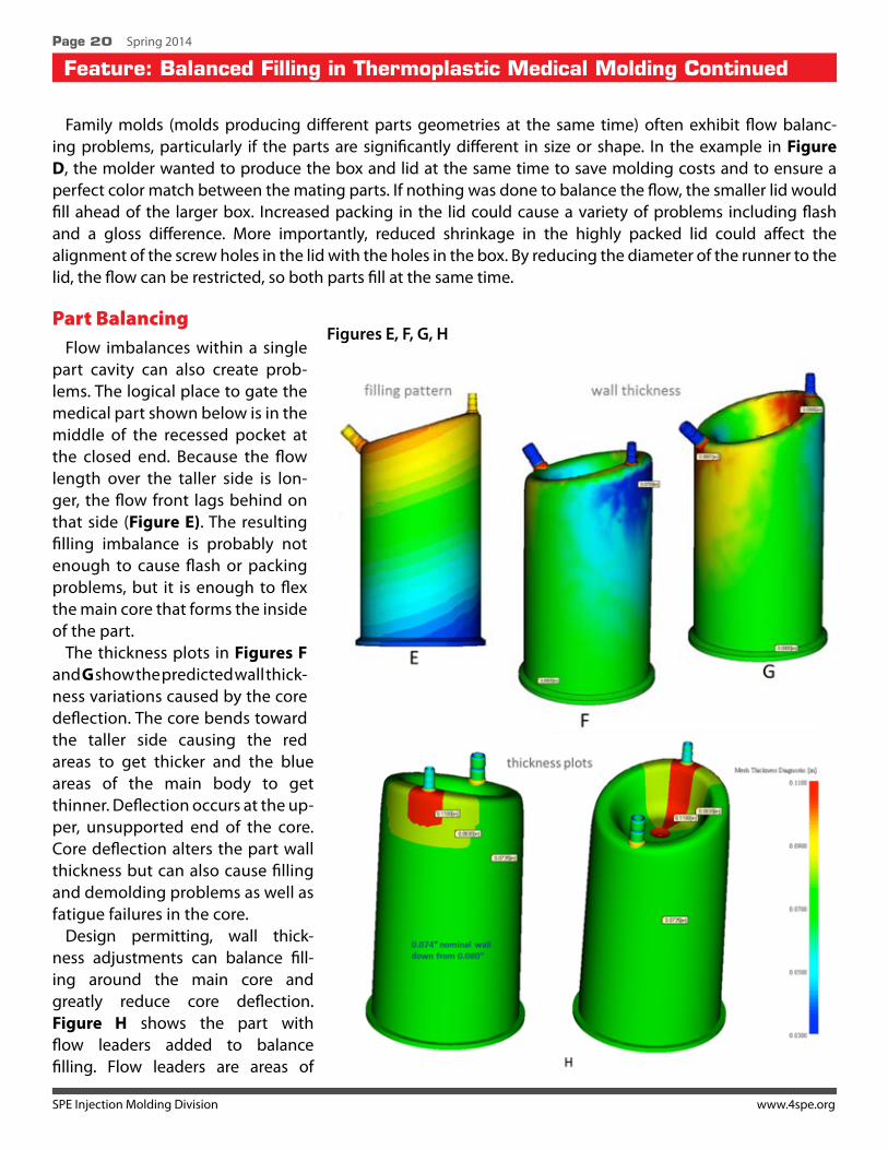
Family molds (molds producing different parts geometries at the same time) often exhibit flow balanc-ing problems, particularly if the parts are significantly different in size or shape. In the example in Figure D, the molder wanted to produce the box and lid at the same time to save molding costs and to ensure a perfect color match between the mating parts. If nothing was done to balance the flow, the smaller lid would fill ahead of the larger box. Increased packing in the lid could cause a variety of problems including flash and a gloss difference. More importantly, reduced shrinkage in the highly packed lid could affect the alignment of the screw holes in the lid with the holes in the box. By reducing the diameter of the runner to the lid, the flow can be restricted, so both parts fill at the same time.
Part Balancing Flow imbalances within a single
part cavity can also create prob-lems. The logical place to gate the medical part shown below is in the middle of the recessed pocket at the closed end. Because the flow length over the taller side is lon-ger, the flow front lags behind on that side (Figure E). The resulting filling imbalance is probably not enough to cause flash or packing problems, but it is enough to flex the main core that forms the inside of the part.
The thickness plots in Figures F and G show the predicted wall thick-ness variations caused by the core deflection. The core bends toward the taller side causing the red areas to get thicker and the blue areas of the main body to get thinner. Deflection occurs at the up-per, unsupported end of the core. Core deflection alters the part wall thickness but can also cause filling and demolding problems as well as fatigue failures in the core.
Design permitting, wall thick-ness adjustments can balance fill-ing around the main core and greatly reduce core deflection. Figure H shows the part with flow leaders added to balance filling. Flow leaders are areas of
Figures E, F, G, H
SPE Injection Molding Division www.4spe.org
Feature: Balanced Filling in Thermoplastic Medical Molding ContinuedPage 21 Spring 2014
increased wall thickness which are intended to improve part filling. In this example, flow leaders were ex-tended from the gate up toward the highest tubing port and partially down the other side. The thickness of the red flow leader was increased from the original nominal wall thickness of 0.080 inches up to 0.110 inches. The yellow-green regions represent the blending area where the thickness tapers down to the new nominal wall thickness. In thickening the longest flow path, the flow leaders also reduced the pressure needed to fill the part. This allowed the nominal wall thickness to be reduced from 0.080 inches to 0.074 inches resulting in weight and cost reduction.
The flow leaders change the original angled flow front (Figure E) to a straighter flow front shape that better balances the melt pressure around the core. This reduces the predicted core deflection by over 70 percent.
As a general rule, parts should fill such that the flow front reaches the part extremities at about the same time. This reduces the required filling pressure and provides more uniform packing and shrinking throughout the part. Gate placement can play a key role in balancing filling. For example, a rounded part would have a shorter flow length and require less filling pressure when gated from the center instead of at the edge.
Not every part needs to be or should be balanced. The penalty for providing balanced flow may outweigh the gains. If filling is straightforward and free of potential problems, then the cost and complexity to add a center gate may not be justified. In the case of long, narrow parts, it is often preferable to gate at one end to align the polymer chains and reduce warpage. Cosmetic constraints may also restrict the gating options. That said, the matter of part balancing should at least be considered.
SummaryBalanced filling can improve the quality and consistency of molded medical parts. Runner balancing in
multi-cavity molds improves the chance that all cavities will fill and pack the same way. This broadens the processing window and improves cavity-to-cavity consistency. Flow balancing is particularly important in family molds, which produce parts that differ significantly in size or shape. Runner balancing is highly recommended for multi-cavity molds.
Flow balancing within parts can be achieved with flow leaders or gate placement, and can reduce problems such as core deflection, excessive filling pressure or localized over or under packing. In some instances, the benefits of balancing flow within parts may not be worth the costs or performance penalties. This needs to be evaluated based on the specific part performance and molding requirements. While not always required, the merits of flow balancing within parts should always be considered.
For more information contact Mark Yeager, Principal Engineer/Engineering Consultant, Bayer Material Science LLC, Pittsburgh, PA. Visit http://info.hotims.com/45608-162
This article originally appeared in Medical Design Briefs, October 2013, page 13-15, Volume 3 Number 10. http://www.medicaldesignbriefs.com/component/con-tent/article/17489


![INTEGRATED NUMERICAL SIMULATION OF INJECTION MOLDING … · injection molding filling simulation [8]. Numerical experiments confirm the reliability and efficiency of the solver. Integrated](https://img.pdfslide.us/doc/110x75/5d0d0f7388c993ed388b4830/integrated-numerical-simulation-of-injection-molding-injection-molding-filling.jpg)

![THERMOPLASTIC ELASTOMERIC (TPE) MATERIALS AND …ipme.ru/e-journals/RAMS/no_12911/02_amin.pdf · microelectronic chips etc.[1,2,4-6,12-14]. 1.4.1. Over molding [15] Over molding means](https://img.pdfslide.us/doc/110x75/6146b0f4f4263007b135576b/thermoplastic-elastomeric-tpe-materials-and-ipmerue-journalsramsno1291102aminpdf.jpg)