Embed Size (px)
Citation preview

Bachmann K27
Installation Guide
Phoenix Sound Systems, Inc.3514 West Liberty RoadAnn Arbor MI 48103
www.phoenixsound.com
phone: 800-651-2444fax: 734-662-0809
e-mail: [email protected]
©2008 Phoenix Sound Systems, Inc.
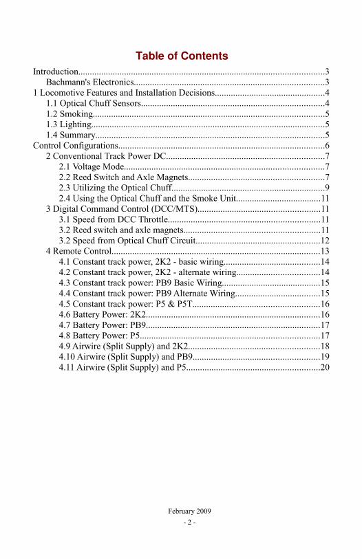
Table of ContentsIntroduction...........................................................................................................3
Bachmann's Electronics...................................................................................31 Locomotive Features and Installation Decisions................................................4
1.1 Optical Chuff Sensors................................................................................41.2 Smoking.....................................................................................................51.3 Lighting......................................................................................................51.4 Summary....................................................................................................5
Control Configurations..........................................................................................62 Conventional Track Power DC.....................................................................7
2.1 Voltage Mode.......................................................................................72.2 Reed Switch and Axle Magnets...........................................................72.3 Utilizing the Optical Chuff...................................................................92.4 Using the Optical Chuff and the Smoke Unit.....................................11
3 Digital Command Control (DCC/MTS).....................................................113.1 Speed from DCC Throttle..................................................................113.2 Reed switch and axle magnets...........................................................113.2 Speed from Optical Chuff Circuit......................................................12
4 Remote Control...........................................................................................134.1 Constant track power, 2K2 - basic wiring..........................................144.2 Constant track power, 2K2 - alternate wiring....................................144.3 Constant track power: PB9 Basic Wiring...........................................154.4 Constant track power: PB9 Alternate Wiring.....................................154.5 Constant track power: P5 & P5T.......................................................164.6 Battery Power: 2K2............................................................................164.7 Battery Power: PB9............................................................................174.8 Battery Power: P5..............................................................................174.9 Airwire (Split Supply) and 2K2.........................................................184.10 Airwire (Split Supply) and PB9.......................................................194.11 Airwire (Split Supply) and P5..........................................................20
February 2009- 2 -
IntroductionBachmann once again brings you an ingeniously and meticulously designed
locomotive that allows you to obtain excellent sound realism to go along with the high level of accuracy and detail that are part of the Spectrum legacy.
Installation varies from easy to adventuresome depending on how you are powering the system and which of the Bachmann features you wish to use. On the initial runs of the K27 there is no friendly way to pick up power. It is possible to install the Phoenix system without soldering.
The installation of the speaker, volume switch, and the other components follows the general instructions in the regular sound system manual. We have included some installation pictures to help you with these aspects of the K27 installation.
Bachmann's ElectronicsInside the tender you will find an early version of the G-Scale control
socket. This is similar to the socket that is found in Aristocraft locomotives and the intention is that eventually you will be able to buy a receiver and sound system of your choice, plug them into this socket and you're done. The socket design works best for systems that combine control and sound on a single board. Phoenix systems are designed to work with DC, DCC and all the various control systems so we do not currently have a plug in configuration for this socket. This manual will show you how to connect the Phoenix system utilizing and modifying the DC Dummy Plug In Board, diagrammed below.
February 2009- 3 -
1 Locomotive Features and Installation DecisionsThe three main electronic systems that affect your control system and the
installation of the Phoenix sound system are the Optical Chuff Sensors, the Smoke Unit and the Lighting circuit. It would seem that the Smoke Unit and the lighting circuit would not affect the sound system installation but you will soon discover that everything is related and life has in many cases not been made easy for the installer.
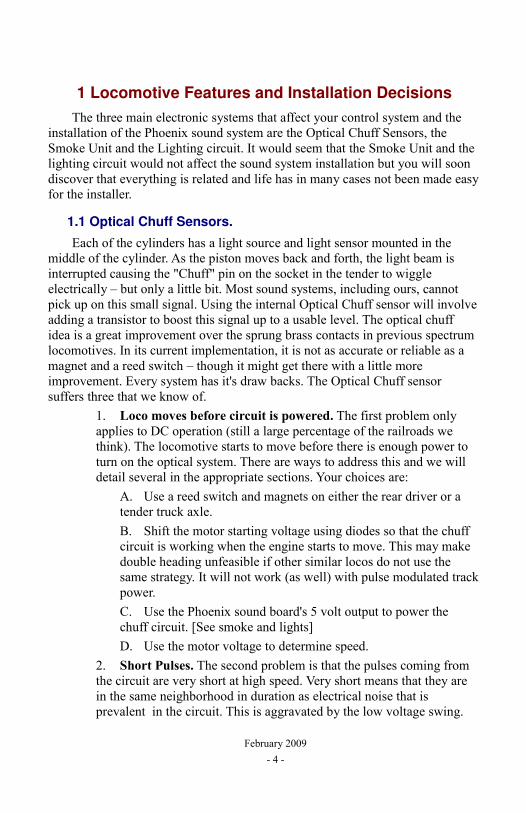
1.1 Optical Chuff Sensors.Each of the cylinders has a light source and light sensor mounted in the
middle of the cylinder. As the piston moves back and forth, the light beam is interrupted causing the "Chuff" pin on the socket in the tender to wiggle electrically – but only a little bit. Most sound systems, including ours, cannot pick up on this small signal. Using the internal Optical Chuff sensor will involve adding a transistor to boost this signal up to a usable level. The optical chuff idea is a great improvement over the sprung brass contacts in previous spectrum locomotives. In its current implementation, it is not as accurate or reliable as a magnet and a reed switch – though it might get there with a little more improvement. Every system has it's draw backs. The Optical Chuff sensor suffers three that we know of.
1. Loco moves before circuit is powered. The first problem only applies to DC operation (still a large percentage of the railroads we think). The locomotive starts to move before there is enough power to turn on the optical system. There are ways to address this and we will detail several in the appropriate sections. Your choices are:
A. Use a reed switch and magnets on either the rear driver or a tender truck axle. B. Shift the motor starting voltage using diodes so that the chuff circuit is working when the engine starts to move. This may make double heading unfeasible if other similar locos do not use the same strategy. It will not work (as well) with pulse modulated track power.C. Use the Phoenix sound board's 5 volt output to power the chuff circuit. [See smoke and lights]D. Use the motor voltage to determine speed.
2. Short Pulses. The second problem is that the pulses coming from the circuit are very short at high speed. Very short means that they are in the same neighborhood in duration as electrical noise that is prevalent in the circuit. This is aggravated by the low voltage swing.
February 2009- 4 -
This problem is addressed by adding filtering (a capacitor) that Bachmann did not realize they needed. Also, the 2K2 system responds better to short chuff signals if the input is configured as active high instead of the standard active low.3. Not Quartered Properly. The chuff signals are not accurately timed with the rotation of the drivers – probably due to manufacturing tolerances. This produces a noticeable irregular chuff cadence which some may decide is a feature but doesn't represent the way a real loco would sound. This is most easily addressed with the Phoenix Systems by enabling chuff averaging. Note that chuff averaging works best if we can also see the motor voltage so we can distinguish between real speed changes and a chuff out of sync.
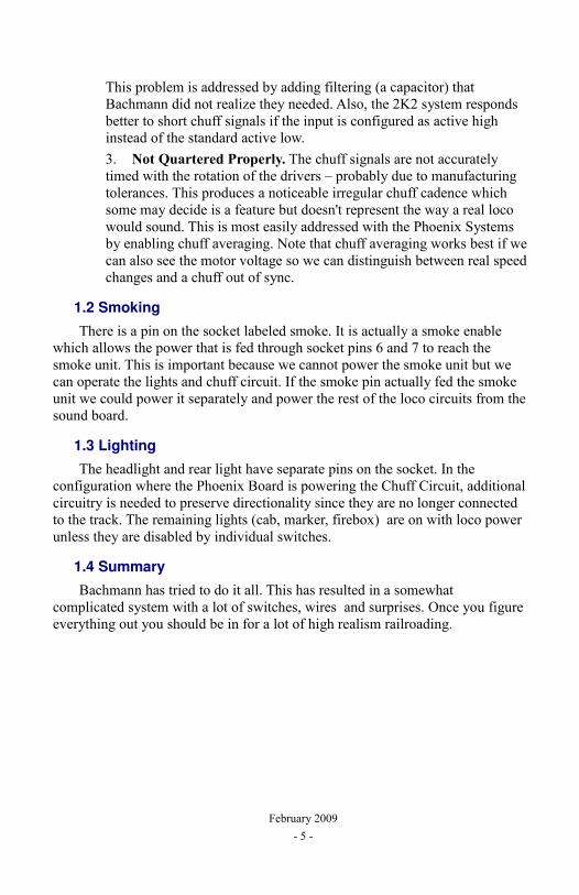
1.2 SmokingThere is a pin on the socket labeled smoke. It is actually a smoke enable
which allows the power that is fed through socket pins 6 and 7 to reach the smoke unit. This is important because we cannot power the smoke unit but we can operate the lights and chuff circuit. If the smoke pin actually fed the smoke unit we could power it separately and power the rest of the loco circuits from the sound board.
1.3 LightingThe headlight and rear light have separate pins on the socket. In the
configuration where the Phoenix Board is powering the Chuff Circuit, additional circuitry is needed to preserve directionality since they are no longer connected to the track. The remaining lights (cab, marker, firebox) are on with loco power unless they are disabled by individual switches.
1.4 SummaryBachmann has tried to do it all. This has resulted in a somewhat
complicated system with a lot of switches, wires and surprises. Once you figure everything out you should be in for a lot of high realism railroading.
February 2009- 5 -
Control ConfigurationsThe three main control strategies are listed below. Find the one that fits
your railroad and proceed to the designated section of this manual.CONVENTIONAL TRACK POWER DC
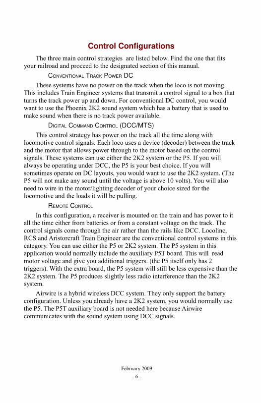
These systems have no power on the track when the loco is not moving. This includes Train Engineer systems that transmit a control signal to a box that turns the track power up and down. For conventional DC control, you would want to use the Phoenix 2K2 sound system which has a battery that is used to make sound when there is no track power available.
DIGITAL COMMAND CONTROL (DCC/MTS)This control strategy has power on the track all the time along with
locomotive control signals. Each loco uses a device (decoder) between the track and the motor that allows power through to the motor based on the control signals. These systems can use either the 2K2 system or the P5. If you will always be operating under DCC, the P5 is your best choice. If you will sometimes operate on DC layouts, you would want to use the 2K2 system. (The P5 will not make any sound until the voltage is above 10 volts). You will also need to wire in the motor/lighting decoder of your choice sized for the locomotive and the loads it will be pulling.
REMOTE CONTROL
In this configuration, a receiver is mounted on the train and has power to it all the time either from batteries or from a constant voltage on the track. The control signals come through the air rather than the rails like DCC. Locolinc, RCS and Aristorcraft Train Engineer are the conventional control systems in this category. You can use either the P5 or 2K2 system. The P5 system in this application would normally include the auxiliary P5T board. This will read motor voltage and give you additional triggers. (the P5 itself only has 2 triggers). With the extra board, the P5 system will still be less expensive than the 2K2 system. The P5 produces slightly less radio interference than the 2K2 system.
Airwire is a hybrid wireless DCC system. They only support the battery configuration. Unless you already have a 2K2 system, you would normally use the P5. The P5T auxiliary board is not needed here because Airwire communicates with the sound system using DCC signals.
February 2009- 6 -
2 Conventional Track Power DC
IN EACH SECTION, WE WILL BEGIN WITH THE SIMPLEST INSTALLATION, WHICH IS VOLTAGE MODE, AND PROCEED TO COVER SPEED BY TRIGGERS. FOR DC OPERATION, YOU SHOULD BE USING THE 2K2 OR PB9 SOUND BOARD.
2.1 Voltage Mode
In this setup, the train speed is determined from the voltage on the track which for this hookup, is the same as the voltage on the motor. The least amount of work to get you going is to wire sound board pins 1 and 2 to the DC dummy board pins J1-1 and J1-12. If you a good at soldering, these wires can be attached either on the dummy board(J1-1 and J1-12) or on the base board(R and L).
The rest of the installation can follow procedures in the appropriate handbook. Mount the volume switch, access jack and install the speaker. The reed switches for whistle and bell activation can be installed if track magnets are used on your layout.
You will have to reconfigure the sound system to use voltage for train speed instead of the trigger inputs. This is also covered in the system handbook.
IF YOU NEGLECT TO DO THIS STEP THE LOCO WILL STAY IN IDLE REGARDLESS OF THE MOTOR VOLTAGE, IT IS WAITING FOR A CONTACT CLOSURE BETWEEN BETWEEN 15 AND 16 (2K2) OR 10 AND 11 (PB9), BUT NOTHING IS HOOKED HERE FOR THE VOLTAGE MODE INSTALLATION.
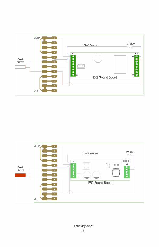
2.2 Reed Switch and Axle Magnets
The next step up in realism and complexity is to install a chuff reed switch on a tender axle and put two magnets on the axle shaft,this follows the standard installation outlined in the sound board manual. If you want to get precisely 4 chuffs per revolution, you can put 4 magnets on the rear loco drive axle and mount a reed switch in the locomotive to sense them. This installation will require using some of the existing wires between the tender and loco or running separate wires for the reed switch. If you use the existing loco to tender chuff wire (goes to pin J1-5) and the ground, you need to put a 100 ohm resistor between our 2K2 pin 16 [PB9 Pin 11] and the loco ground (Pin J1-7). Otherwise the Phoenix input diodes will be in parallel with the DC Dummy board diodes and all the electrical load for the loco will shift to the Phoenix diode (because they are of the more efficient Schottky type). There is probably adequate reserve in the Phoenix design for this extra loading, but this wiring situation is not protected by the on board fuse and you risk burning out one or more Phoenix input diodes and damaging the Phoenix Sound board.
February 2009- 7 -
February 2009- 8 -
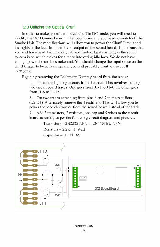
2.3 Utilizing the Optical Chuff
In order to make use of the optical chuff in DC mode, you will need to modify the DC Dummy board in the locomotive and you need to switch off the Smoke Unit. The modifications will allow you to power the Chuff Circuit and the lights in the loco from the 5 volt output on the sound board. This means that you will have head, tail, marker, cab and firebox lights as long as the sound system is on which makes for a more interesting idle loco. We do not have enough power to run the smoke unit. You should change the input sense on the chuff trigger to be active high and you will probably want to use chuff averaging.
Begin by removing the Bachmann Dummy board from the tender.1. Isolate the lighting circuits from the track. This involves cutting two circuit board traces. One goes from J1-1 to J1-4, the other goes from J1-8 to J1-12.2. Cut two traces extending from pins 6 and 7 to the rectifiers (D2,D3). Alternately remove the 4 rectifiers. This will allow you to power the loco electronics from the sound board instead of the track.3. Add 3 transistors, 2 resistors, one cap and 5 wires to the circuit board assembly as per the following circuit diagram and pictures.
Transistors – 2N2222 NPN or 2N4401BU NPNResistors – 2.2K ½ WattCapacitor – .1 μfd 6V
February 2009- 9 -
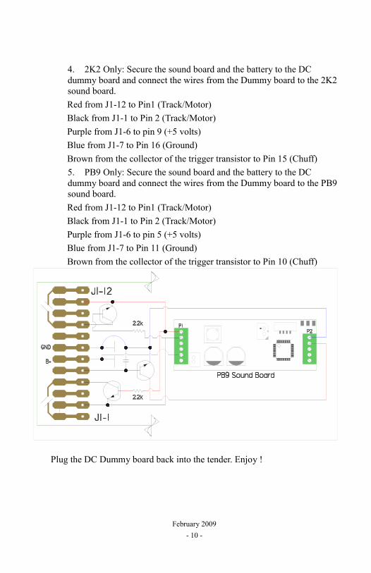
4. 2K2 Only: Secure the sound board and the battery to the DC dummy board and connect the wires from the Dummy board to the 2K2 sound board.Red from J1-12 to Pin1 (Track/Motor)Black from J1-1 to Pin 2 (Track/Motor)Purple from J1-6 to pin 9 (+5 volts)Blue from J1-7 to Pin 16 (Ground)Brown from the collector of the trigger transistor to Pin 15 (Chuff)5. PB9 Only: Secure the sound board and the battery to the DC dummy board and connect the wires from the Dummy board to the PB9 sound board.Red from J1-12 to Pin1 (Track/Motor)Black from J1-1 to Pin 2 (Track/Motor)Purple from J1-6 to pin 5 (+5 volts)Blue from J1-7 to Pin 11 (Ground)Brown from the collector of the trigger transistor to Pin 10 (Chuff)
Plug the DC Dummy board back into the tender. Enjoy !
February 2009- 10 -
2.4 Using the Optical Chuff and the Smoke Unit
For this option, you will have to delve into the loco and separate the smoke unit power from the lighting power. Right now, we do not have details on how to do this and leave it to the most adventuresome modelers
3 Digital Command Control (DCC/MTS)
3.1 Speed from DCC Throttle
The simplest way to get speed is from the DCC control signals that are telling the motor how fast to go. All that's needed is to connect the sound system to the track inputs. We show you how to make connections to the DC dummy board but you can alternately connect to the Bachmann Main board.
1. Remove the dummy board and unsolder (or clip) the motor chokes. This will isolate the motor from the track.
2. Isolate the directional lighting circuits by cutting the traces from J1-1 to J1-4 and from J1-8 to J1-12. The decoder head and rear light outputs will be hooked to the lighting circuits.
3. Connect decoder function wires to the dummy board for the remaining lights and the smoke enable if you will be using it.
4. Connect track wires to the decoder and to the sound system.5. Connect motor pins to the decoder (Orange, Gray)6. Configure the sound system to recognize speed by DCC instead of
triggers. Phoenix steam sounds come configured to recognize the chuff input. On the P5 and PB9 this can be done by setting CV 49 to 1. With the 2K2 sound board you will need to do the configuration procedure. Follow the same instructions for changing to "Speed from Voltage". If you have the computer interface you can use it to more easily make these changes.
7. If you use decoder functions for cab lights, smoke on/off, marker lights, firebox lights etc. you will conflict with the default sound function assignments. With the computer interface you can reassign the sounds to different functions or just turn them off. A second approach is to give the loco and sound decoder different addresses and consist them together. Usually you will make the sound system the lead loco, and switch to the second address to fiddle with smoke, lights etc.
3.2 Reed switch and axle magnets
This is the same as DC. See the DC section 2.2.
February 2009- 11 -
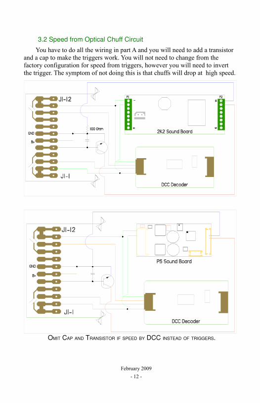
3.2 Speed from Optical Chuff Circuit
You have to do all the wiring in part A and you will need to add a transistor and a cap to make the triggers work. You will not need to change from the factory configuration for speed from triggers, however you will need to invert the trigger. The symptom of not doing this is that chuffs will drop at high speed.
OMIT CAP AND TRANSISTOR IF SPEED BY DCC INSTEAD OF TRIGGERS.
February 2009- 12 -
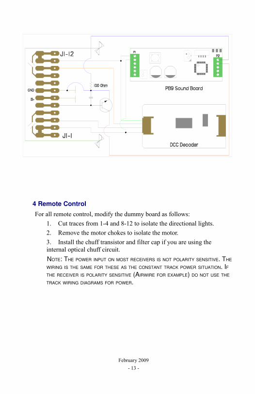
4 Remote ControlFor all remote control, modify the dummy board as follows:
1. Cut traces from 1-4 and 8-12 to isolate the directional lights.2. Remove the motor chokes to isolate the motor.3. Install the chuff transistor and filter cap if you are using the internal optical chuff circuit.NOTE: THE POWER INPUT ON MOST RECEIVERS IS NOT POLARITY SENSITIVE. THE WIRING IS THE SAME FOR THESE AS THE CONSTANT TRACK POWER SITUATION. IF THE RECEIVER IS POLARITY SENSITIVE (AIRWIRE FOR EXAMPLE) DO NOT USE THE TRACK WIRING DIAGRAMS FOR POWER.
February 2009- 13 -
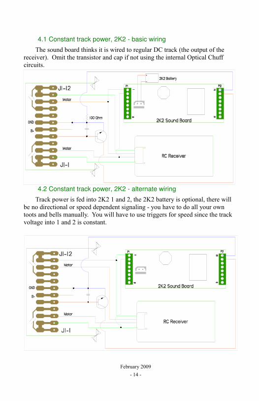
4.1 Constant track power, 2K2 - basic wiring
The sound board thinks it is wired to regular DC track (the output of the receiver). Omit the transistor and cap if not using the internal Optical Chuff circuits.
4.2 Constant track power, 2K2 - alternate wiring
Track power is fed into 2K2 1 and 2, the 2K2 battery is optional, there will be no directional or speed dependent signaling - you have to do all your own toots and bells manually. You will have to use triggers for speed since the track voltage into 1 and 2 is constant.
February 2009- 14 -
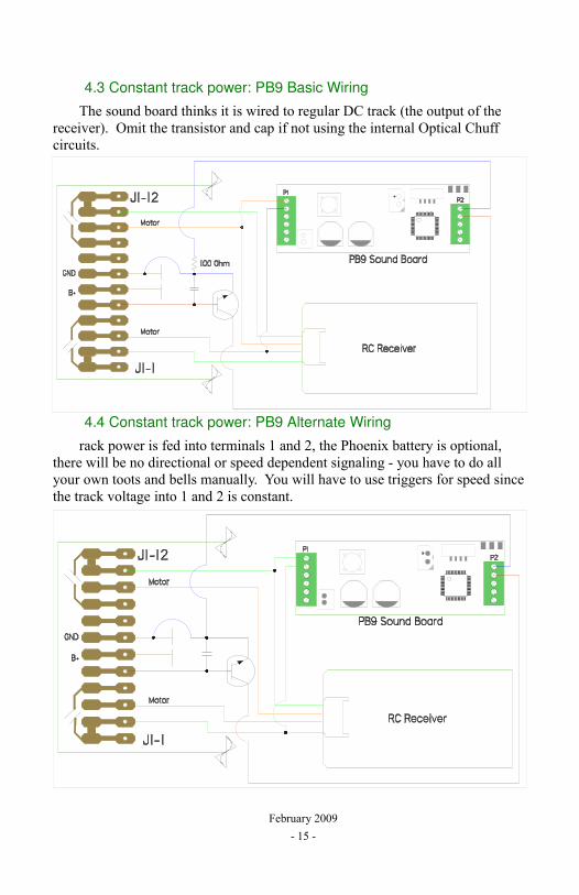
4.3 Constant track power: PB9 Basic Wiring
The sound board thinks it is wired to regular DC track (the output of the receiver). Omit the transistor and cap if not using the internal Optical Chuff circuits.
4.4 Constant track power: PB9 Alternate Wiring
rack power is fed into terminals 1 and 2, the Phoenix battery is optional, there will be no directional or speed dependent signaling - you have to do all your own toots and bells manually. You will have to use triggers for speed since the track voltage into 1 and 2 is constant.
February 2009- 15 -
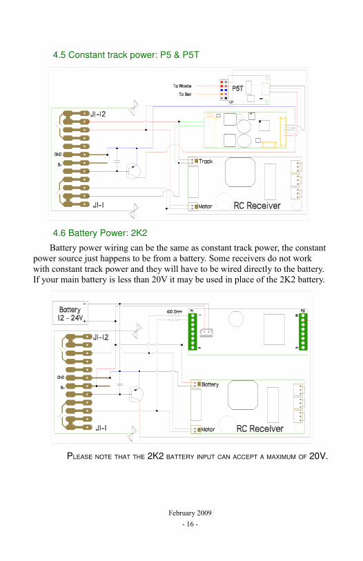
4.5 Constant track power: P5 & P5T
4.6 Battery Power: 2K2
Battery power wiring can be the same as constant track power, the constant power source just happens to be from a battery. Some receivers do not work with constant track power and they will have to be wired directly to the battery. If your main battery is less than 20V it may be used in place of the 2K2 battery.
PLEASE NOTE THAT THE 2K2 BATTERY INPUT CAN ACCEPT A MAXIMUM OF 20V.
February 2009- 16 -
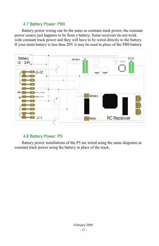
4.7 Battery Power: PB9
Battery power wiring can be the same as constant track power, the constant power source just happens to be from a battery. Some receivers do not work with constant track power and they will have to be wired directly to the battery. If your main battery is less than 20V it may be used in place of the PB9 battery.
4.8 Battery Power: P5
Battery power installations of the P5 are wired using the same diagrams as constant track power using the battery in place of the track.
February 2009- 17 -
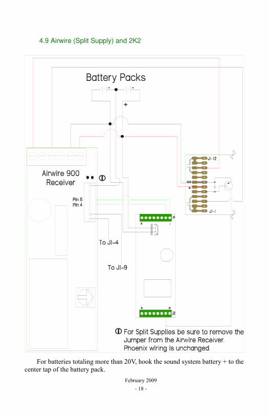
4.9 Airwire (Split Supply) and 2K2
For batteries totaling more than 20V, hook the sound system battery + to the center tap of the battery pack.
February 2009- 18 -
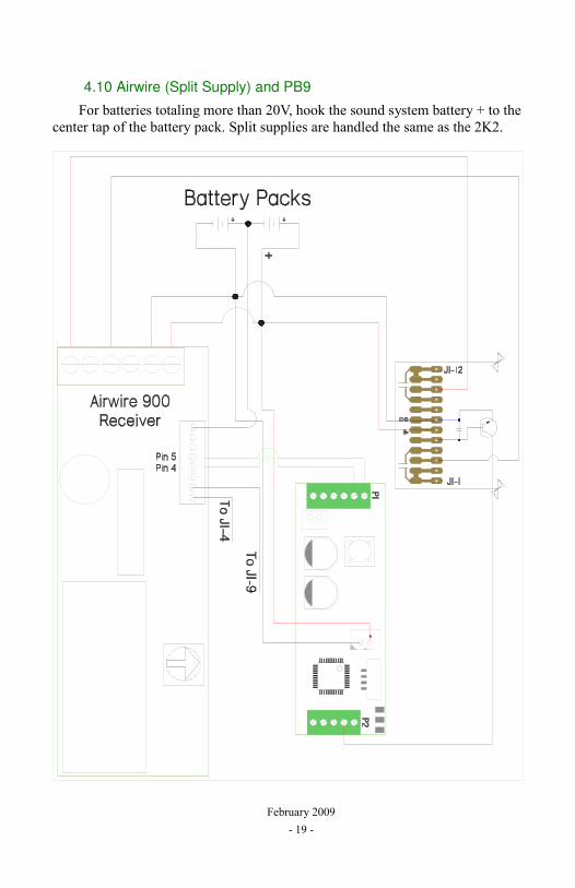
4.10 Airwire (Split Supply) and PB9
For batteries totaling more than 20V, hook the sound system battery + to the center tap of the battery pack. Split supplies are handled the same as the 2K2.
February 2009- 19 -
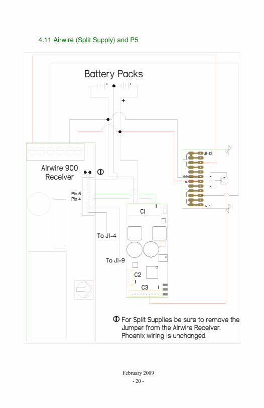
4.11 Airwire (Split Supply) and P5
February 2009- 20 -


![GIS-K27 Food Allergyocw.usu.ac.id/.../gis_20102011_slide_food_allergy.pdf · Title: Microsoft PowerPoint - GIS-K27 Food Allergy [Compatibility Mode] Author: ACER MEU Created Date:](https://img.pdfslide.us/doc/110x75/6036531578942c4eb076fd22/gis-k27-food-title-microsoft-powerpoint-gis-k27-food-allergy-compatibility-mode.jpg)