Embed Size (px)
Citation preview

BA 098D/06/en/04.0450107138valid as of software versionVersion 1.00.XX
dosimagElectromagnetic flow measuring system
For filling applications
Operating Instructions
Dosimag
2 Endress+Hauser
Dosimag brief operating instructionsYou can commission your device quickly and easily with the following brief operating instructions:
Safety instructions → Page 5 ff.
▼
Installation → Page 8 ff.
▼
Wiring → Page 16 ff.
▼
Operation → Page 19 ff.
▼
Customer-specific configuration
Complex measuring tasks require the configuration of additional functions which users can individually select, configure and adapt to their process conditions via the function matrix.
! Note! A detailed description of all the functions as well as a detailed overview of the function matrix is provided in Section "Appendix - Function description, Page 42 ff..
Dosimag Endress+Hauser
Endress+Hauser 3
Table of contents
1 Safety instructions . . . . . . . . . . . . . . 51.1 Designated use . . . . . . . . . . . . . . . . . . . . . . . . 51.2 Installation, commissioning and operation . . . 51.3 Operational safety . . . . . . . . . . . . . . . . . . . . . . 51.4 Return . . . . . . . . . . . . . . . . . . . . . . . . . . . . . . . 61.5 Notes on safety conventions and icons . . . . . . 6
2 Identification . . . . . . . . . . . . . . . . . . . 72.1 Device designation . . . . . . . . . . . . . . . . . . . . . 7
2.1.1 Nameplate . . . . . . . . . . . . . . . . . . . . . . 72.2 Certificates and approvals . . . . . . . . . . . . . . . . 72.3 Registered trademarks . . . . . . . . . . . . . . . . . . 7
3 Installation. . . . . . . . . . . . . . . . . . . . . 83.1 Incoming acceptance, transport, storage . . . . 8
3.1.1 Incoming acceptance . . . . . . . . . . . . . 83.1.2 Transport . . . . . . . . . . . . . . . . . . . . . . . 83.1.3 Storage . . . . . . . . . . . . . . . . . . . . . . . . . 8
3.2 Installation conditions . . . . . . . . . . . . . . . . . . . 93.2.1 Dimensions . . . . . . . . . . . . . . . . . . . . . . 93.2.2 Mounting location . . . . . . . . . . . . . . . . . 93.2.3 Orientation . . . . . . . . . . . . . . . . . . . . . 113.2.4 Inlet and outlet run . . . . . . . . . . . . . . . 123.2.5 Vibrations . . . . . . . . . . . . . . . . . . . . . . 123.2.6 Adapters . . . . . . . . . . . . . . . . . . . . . . . 133.2.7 Nominal diameter and flow rate . . . . . 14
3.3 Post-installation check . . . . . . . . . . . . . . . . . . 15
4 Wiring . . . . . . . . . . . . . . . . . . . . . . . . 164.1 Connecting the measuring unit . . . . . . . . . . . 16
4.1.1 Wiring diagram . . . . . . . . . . . . . . . . . . 164.1.2 Ground connection . . . . . . . . . . . . . . . 174.1.3 Cable specification . . . . . . . . . . . . . . . 174.1.4 Connection example . . . . . . . . . . . . . 17
4.2 Potential equalisation . . . . . . . . . . . . . . . . . . . 184.3 Degree of protection . . . . . . . . . . . . . . . . . . . 184.4 Post-connection check . . . . . . . . . . . . . . . . . 18
5 Operation . . . . . . . . . . . . . . . . . . . . . 195.1 FieldTool operating program . . . . . . . . . . . . . 195.2 Structure of the function matrix . . . . . . . . . . . 20
5.2.1 General notes . . . . . . . . . . . . . . . . . . . 21
6 Commissioning . . . . . . . . . . . . . . . . 226.1 Function check . . . . . . . . . . . . . . . . . . . . . . . 226.2 Switching on the measuring device . . . . . . . . 22
7 Maintenance . . . . . . . . . . . . . . . . . . . 23
8 Accessories/spare parts. . . . . . . . . . 24
9 Trouble-shooting . . . . . . . . . . . . . . . 259.1 Trouble-shooting instructions . . . . . . . . . . . . . 259.2 Types of error . . . . . . . . . . . . . . . . . . . . . . . . . 25
9.2.1 Type of error . . . . . . . . . . . . . . . . . . . . 259.2.2 Error message types . . . . . . . . . . . . . . 25
9.3 System error messages (FieldTool) . . . . . . . . 269.4 Process error messages (FieldTool) . . . . . . . . 279.5 Process errors without message . . . . . . . . . . 289.6 Response of outputs to errors . . . . . . . . . . . . 289.7 Spare parts . . . . . . . . . . . . . . . . . . . . . . . . . . . 30
9.7.1 Storage of the replacement electronics module . . . . . . . . . . . . . . . . . . . . . . . . . 30
9.8 Installing/removing the electronics . . . . . . . . . 319.9 Software history . . . . . . . . . . . . . . . . . . . . . . . 329.10 Return . . . . . . . . . . . . . . . . . . . . . . . . . . . . . . . 329.11 Disposal . . . . . . . . . . . . . . . . . . . . . . . . . . . . . 32
10 Technical data . . . . . . . . . . . . . . . . . 3310.1 Technical data . . . . . . . . . . . . . . . . . . . . . . . . 33
10.1.1 Application . . . . . . . . . . . . . . . . . . . . . . 3310.1.2 Function and system design . . . . . . . . 3310.1.3 Input . . . . . . . . . . . . . . . . . . . . . . . . . . . 3310.1.4 Output . . . . . . . . . . . . . . . . . . . . . . . . . 3310.1.5 Power supply . . . . . . . . . . . . . . . . . . . . 3410.1.6 Performance characteristics . . . . . . . . 3410.1.7 Operating conditions: Installation . . . . 3510.1.8 Operating conditions: Environment . . . 3510.1.9 Operating conditions: Process . . . . . . 3510.1.10 Mechanical construction . . . . . . . . . . 3610.1.11 User interface . . . . . . . . . . . . . . . . . . 3710.1.12 Certificates and approvals . . . . . . . . . 3710.1.13 Ordering information . . . . . . . . . . . . . 3710.1.14 Accessories . . . . . . . . . . . . . . . . . . . . 3810.1.15 Supplementary Documentation . . . . . 38
10.2 Dimensions . . . . . . . . . . . . . . . . . . . . . . . . . . . 3910.2.1 Dosimag dimensions . . . . . . . . . . . . . . 3910.2.2 Process connection dimensions . . . . . 40
Dosimag Endress+Hauser
4 Endress+Hauser
11 Appendix - Function description . . 4211.1 Function group "MEASURING VALUES" . . . . 4211.2 Function group "SYSTEM UNITS" . . . . . . . . . 4311.3 Function group "PULSE OUTPUT" . . . . . . . . 4411.4 Function group "STATUS OUTPUT" . . . . . . . 46
11.4.1 Switching response of the status output . . . . . . . . . . . . . . . . . . . 46
11.5 Function group "COMMUNICATION" . . . . . . 4711.6 Function group "PROCESS PARAMETER" . . 4711.7 Function group "SYSTEM PARAMETER" . . . . 4911.8 Function group "SENSOR PARAMETER" . . . 5011.9 Function group "SUPERVISION" . . . . . . . . . . 5111.10 Function group "SIMULATION" . . . . . . . . . . . 5211.11 Function group "SENSOR VERSION" . . . . . . 5211.12 Function group "AMPLIFIER VERSION" . . . . 52
Index. . . . . . . . . . . . . . . . . . . . . . . . . . . . . . 53
Dosimag Safety instructions
Endress+Hauser 5
1 Safety instructions
1.1 Designated useThe measuring device described in these Operating Instructions is to be used only for measuring the flow rate of conductive liquids in closed pipes. A minimum conductivity of 20 µS/cm is required for measuring demineralised water. Most fluids can be metered, provided they have a minimum conductivity of 5 µS/cm, for example:• Beverage: beer, softdrinks, mineral water, juices, wine, molasses• Food: milk, yoghurt, mayonnaise, soups• Cosmetics: body milk, bath-shower products• Various: acids, alkalis, plastes, pulp, wastewater, sewage sludge
Resulting from incorrect use or from use other than that designated, the operational safety of the measuring devices can be suspended. The manufacturer accepts no liability for damages being produced from this.
1.2 Installation, commissioning and operationNote the following points:• Installation, connection to the electricity supply, commissioning and maintenance of
the device must be carried out by trained, qualified specialists authorised to perform such work by the facility's owner-operator. The specialist must have read and understood these Operating Instructions and must follow the instructions they contain.
• The device must be operated by persons authorised and trained by the facility's owner-operator. Strict compliance with the instructions in the Operating Instructions is mandatory.
• Endress+Hauser will be happy to assist in clarifying the chemical resistance properties of parts wetted by special fluids, including fluids used for cleaning. However the user is responsible for the choice of fluid wetted materials for their in-process resistance to corrosion. The manufacturer refuses to accept liability.
• The installer must ensure that the measuring system is correctly wired in accordance with the wiring diagrams. The transmitter must be grounded, unless the power supply is galvanically isolated.
• Invariably, local regulations governing the opening and repair of electrical devices apply.
1.3 Operational safetyNote the following points:• The measuring device complies with the general safety requirements in accordance
with EN 61010 and the EMC requirements of EN 61326/A1.For Canada, the Dosimag has been inspected and approved both to the safety requirements as per CSA-C22.2 No. 142-M1987 and to CAN/CSA-C22.2 No. 1010.1-92.
• The manufacturer reserves the right to modify technical data without prior notice. Your E+H distributor will supply you with current information and updates to these Operating Instructions.
Safety instructions Dosimag
6 Endress+Hauser
1.4 ReturnThe following procedures must be carried out before a flowmeter requiring repair or calibration, for example, is returned to Endress+Hauser:• Always enclose a duly completed “Declaration of contamination” form. Only then can
Endress+Hauser transport, examine and repair a returned device.• Enclose special handling instructions if necessary, for example a safety data sheet as
per EN 91/155/EEC.• Remove all residues. Pay special attention to the grooves for seals and crevices which
could contain residues. This is particularly important if the substance is hazardous to health, e.g. flammable, toxic, caustic, carcinogenic, etc.
! Note! You will find a “Declaration of contamination” form at the back of this manual.
# Warning! • Do not return a measuring device if you are not absolutely certain that all traces of
hazardous substances have been removed, e.g. substances which have penetrated crevices or diffused through plastic.
• Costs incurred for waste disposal and injury (burns, etc.) due to inadequate cleaning will be charged to the owner-operator.
1.5 Notes on safety conventions and iconsThe devices are designed to meet state-of-the-art safety requirements, have been tested, and left the factory in a condition in which they are safe to operate. The devices comply with the applicable standards and regulations in accordance with EN 61010 “Protection Measures for Electrical Equipment for Measurement, Control, Regulation and Laboratory Procedures”. They can, however, be a source of danger if used incorrectly or for use other than that designated.Consequently, always pay particular attention to the safety instructions indicated in these Operating Instructions by the following icons:
# Warning! “Warning” indicates an action or procedure which, if not performed correctly, can result in injury or a safety hazard. Comply strictly with the instructions and proceed with care.
" Caution! “Caution” indicates an action or procedure which, if not performed correctly, can result in incorrect operation or destruction of the device. Comply strictly with the instructions.
! Note! “Note” indicates an action or procedure which, if not performed correctly, can have an indirect effect on operation or trigger an unexpected response on the part of the device.
Dosimag Identification
Endress+Hauser 7
2 Identification
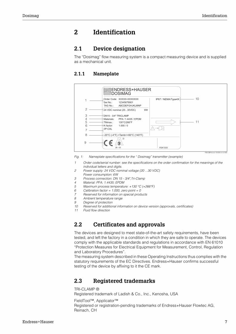
2.1 Device designationThe “Dosimag” flow measuring system is a compact measuring device and is supplied as a mechanical unit.
2.1.1 Nameplate
F06-5BHxxxxx-18-06-xx-xx-000
Fig. 1: Nameplate specifications for the “ Dosimag” transmitter (example)
1 Order code/serial number: see the specifications on the order confirmation for the meanings of the individual letters and digits.
2 Power supply: 24 VDC nominal voltage (20 ...30 VDC)Power consumption: 6W
3 Process connection: DN 15 - 3/4",Tri-Clamp4 Material: PFA; 1.4435; EPDM5 Maximum process temperature: +130 °C (+266°F)6 Calibration factor = 1.000, zero point = 07 Reserved for information on special products8 Ambient temperature range9 Degree of protection10 Reserved for additional information on device version (approvals, certificates)11 Fluid flow direction
2.2 Certificates and approvalsThe devices are designed to meet state-of-the-art safety requirements, have been tested, and left the factory in a condition in which they are safe to operate. The devices comply with the applicable standards and regulations in accordance with EN 61010 “Protection Measures for Electrical Equipment for Measurement, Control, Regulation and Laboratory Procedures”. The measuring system described in these Operating Instructions thus complies with the statutory requirements of the EC Directives. Endress+Hauser confirms successful testing of the device by affixing to it the CE mark.
2.3 Registered trademarksTRI-CLAMP ®Registered trademark of Ladish & Co., Inc., Kenosha, USA
FieldTool™, Applicator™Registered or registration-pending trademarks of Endress+Hauser Flowtec AG, Reinach, CH
i
-20°C (-4°F) <Tamb<+60°C (140°F)
DOSIMAGENDRESS+HAUSER
Materials:
TMmax.: 130°C/266°F
PFA / 1.4435 / EPDM
Order Code:
24 VDC nominal (20...30VDC)
TAG No.:
DN15 - 3/4" TRICLAMP
Ser.No.:
XXXXX-XXXXXXX
12345678901
ABCDEFGHJKLMNP
IP67 / NEMA/Type4X
6W
FEK133328 - 03
R
1.000 / 0K-factor:
3P-CAL
1
2
34567
8
9
10
11
Installation Dosimag
8 Endress+Hauser
3 Installation
3.1 Incoming acceptance, transport, storage
3.1.1 Incoming acceptanceOn receipt of the goods, check the following points:• Check the packaging and the contents for damage.• Check the shipment, make sure nothing is missing and that the scope of supply
matches your order.
3.1.2 TransportTransport the devices to the measuring point in the containers in which they are delivered.
3.1.3 StorageNote the following points:• Pack the measuring device in such a way as to protect it reliably against impact for
storage (and transportation). The original packaging provides optimum protection.• The permissible storage temperature is -10...+50 °C (preferably +20 °C).• The measuring device must be protected against direct sunlight during storage in
order to avoid unacceptably high surface temperatures.• Choose a storage location where moisture does not collect in the measuring device.
This will help prevent fungus and bacteria infestation which can damage the liner.
Dosimag Installation
Endress+Hauser 9
3.2 Installation conditions
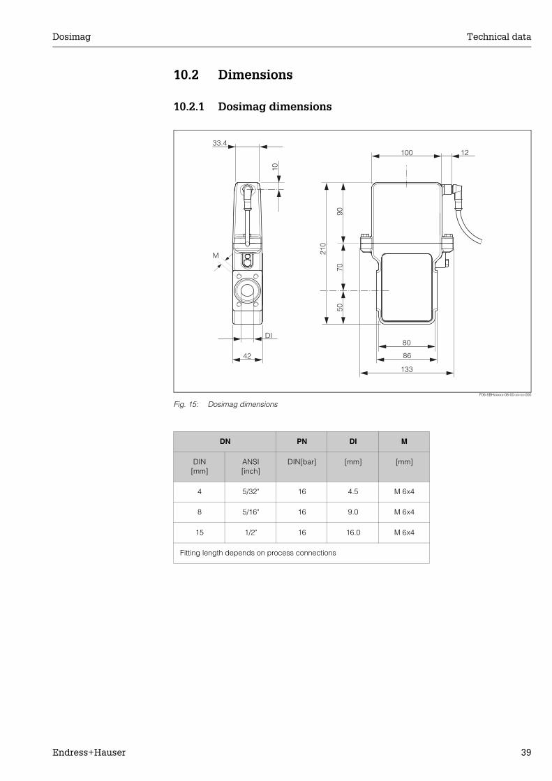
3.2.1 DimensionsThe dimensions and lengths can be found on Page 39.
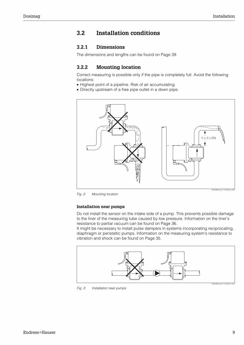
3.2.2 Mounting locationCorrect measuring is possible only if the pipe is completely full. Avoid the following locations:• Highest point of a pipeline. Risk of air accumulating.• Directly upstream of a free pipe outlet in a down pipe.
F06-5BHxxxxx-11-00-00-xx-000
Fig. 2: Mounting location
Installation near pumps
Do not install the sensor on the intake side of a pump. This prevents possible damage to the liner of the measuring tube caused by low pressure. Information on the liner's resistance to partial vacuum can be found on Page 36.It might be necessary to install pulse dampers in systems incorporating reciprocating, diaphragm or peristaltic pumps. Information on the measuring system's resistance to vibration and shock can be found on Page 35.
F06-5BHxxxxx-11-00-00-xx-001
Fig. 3: Installation near pumps
h 2 x DN³
Installation Dosimag
10 Endress+Hauser
Partially filled pipes
Partially filled pipes with gradients necessitate a drain-type configuration.
F06-5BHxxxxx-11-00-00-xx-002
Fig. 4: Installation in partially filled pipe
Down pipes
Install a siphon or a vent valve downstream of the sensor in down pipes longer than 5 meters. This prevents possible damage to the liner of the measuring tube caused by low pressure. These measures also prevent the system losing prime, which could cause air inclusions. Information on the liner's resistance to partial vacuum can be found on Page 36.
F06-5BHxxxxx-11-00-00-xx-003
Fig. 5: Measures for installation in down pipes (1 = vent valve; 2= siphon)
³ 5 x DN
³ 2 x DN
> 5
m
2
1
Dosimag Installation
Endress+Hauser 11
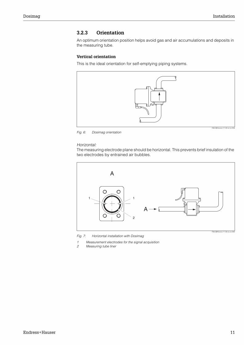
3.2.3 OrientationAn optimum orientation position helps avoid gas and air accumulations and deposits in the measuring tube.
Vertical orientation
This is the ideal orientation for self-emptying piping systems.
F06-5BHxxxxx-11-00-xx-xx-004
Fig. 6: Dosimag orientation
Horizontal:The measuring electrode plane should be horizontal. This prevents brief insulation of the two electrodes by entrained air bubbles.
F06-5BHxxxxx-11-00-xx-xx-000
Fig. 7: Horizontal installation with Dosimag
1 Measurement electrodes for the signal acquisition2 Measuring tube liner
A
1 1
A2
Installation Dosimag
12 Endress+Hauser
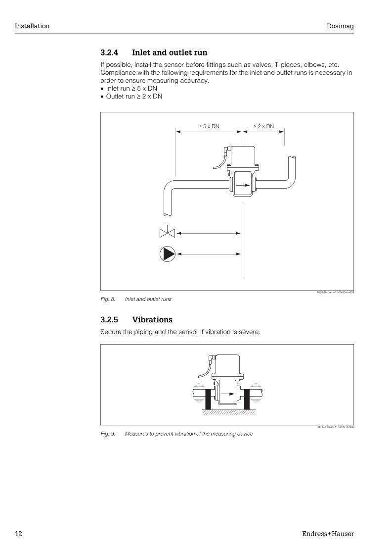
3.2.4 Inlet and outlet runIf possible, install the sensor before fittings such as valves, T-pieces, elbows, etc. Compliance with the following requirements for the inlet and outlet runs is necessary in order to ensure measuring accuracy.• Inlet run ≥ 5 x DN• Outlet run ≥ 2 x DN
F06-5BHxxxxx-11-00-00-xx-005
Fig. 8: Inlet and outlet runs
3.2.5 VibrationsSecure the piping and the sensor if vibration is severe.
F06-5BHxxxxx-11-00-00-xx-006
Fig. 9: Measures to prevent vibration of the measuring device
³ 5 x DN ³ 2 x DN
Dosimag Installation
Endress+Hauser 13
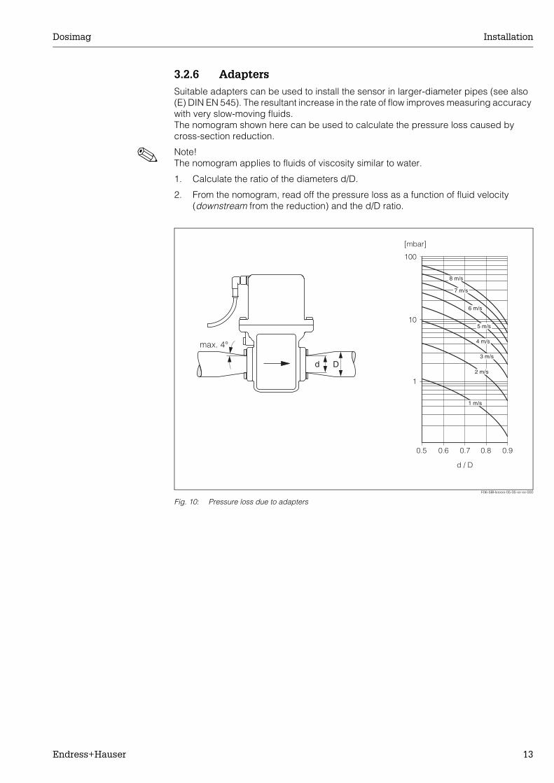
3.2.6 AdaptersSuitable adapters can be used to install the sensor in larger-diameter pipes (see also (E) DIN EN 545). The resultant increase in the rate of flow improves measuring accuracy with very slow-moving fluids.The nomogram shown here can be used to calculate the pressure loss caused by cross-section reduction.
! Note! The nomogram applies to fluids of viscosity similar to water.
1. Calculate the ratio of the diameters d/D.
2. From the nomogram, read off the pressure loss as a function of fluid velocity (downstream from the reduction) and the d/D ratio.
F06-5BHxxxxx-05-05-xx-xx-000
Fig. 10: Pressure loss due to adapters
Dd
max. 4°
100
10
0.5
d / D
[mbar]
0.6 0.7 0.8 0.9
1 m/s
2 m/s
3 m/s
4 m/s
5 m/s
6 m/s
7 m/s
8 m/s
1
Installation Dosimag
14 Endress+Hauser
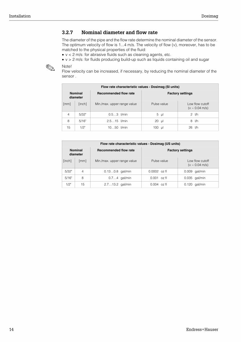
3.2.7 Nominal diameter and flow rateThe diameter of the pipe and the flow rate determine the nominal diameter of the sensor. The optimum velocity of flow is 1...4 m/s. The velocity of flow (v), moreover, has to be matched to the physical properties of the fluid:• v < 2 m/s: for abrasive fluids such as cleaning agents, etc.• v > 2 m/s: for fluids producing build-up such as liquids containing oil and sugar
! Note! Flow velocity can be increased, if necessary, by reducing the nominal diameter of the sensor .
Flow rate characteristic values - Dosimag (SI units)
Nominal diameter
Recommended flow rate Factory settings
[mm] [inch] Min./max. upper range value Pulse value Low flow cutoff (v ~ 0.04 m/s)
4 5/32" 0.5…3 l/min 5 µl 2 l/h
8 5/16" 2.5…15 l/min 20 µl 8 l/h
15 1/2" 10…50 l/min 100 µl 26 l/h
Flow rate characteristic values - Dosimag (US units)
Nominal diameter
Recommended flow rate Factory settings
[inch] [mm] Min./max. upper range value Pulse value Low flow cutoff (v ~ 0.04 m/s)
5/32" 4 0.13…0.8 gal/min 0.0002 oz fl 0.009 gal/min
5/16" 8 0.7…4 gal/min 0.001 oz fl 0.035 gal/min
1/2" 15 2.7…13.2 gal/min 0.004 oz fl 0.120 gal/min
Dosimag Installation
Endress+Hauser 15
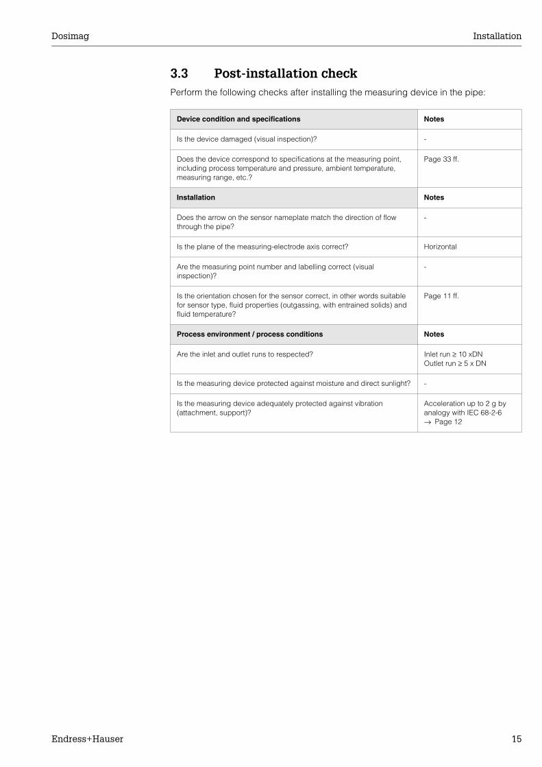
3.3 Post-installation checkPerform the following checks after installing the measuring device in the pipe:
Device condition and specifications Notes
Is the device damaged (visual inspection)? -
Does the device correspond to specifications at the measuring point, including process temperature and pressure, ambient temperature, measuring range, etc.?
Page 33 ff.
Installation Notes
Does the arrow on the sensor nameplate match the direction of flow through the pipe?
-
Is the plane of the measuring-electrode axis correct? Horizontal
Are the measuring point number and labelling correct (visual inspection)?
-
Is the orientation chosen for the sensor correct, in other words suitable for sensor type, fluid properties (outgassing, with entrained solids) and fluid temperature?
Page 11 ff.
Process environment / process conditions Notes
Are the inlet and outlet runs to respected? Inlet run ≥ 10 xDNOutlet run ≥ 5 x DN
Is the measuring device protected against moisture and direct sunlight? -
Is the measuring device adequately protected against vibration (attachment, support)?
Acceleration up to 2 g by analogy with IEC 68-2-6→ Page 12
Wiring Dosimag
16 Endress+Hauser
4 Wiring
4.1 Connecting the measuring unit
# Warning! • Risk of electric shock. Switch off the power supply before opening the device. Do not
install or wire the device while it is connected to the power supply. Failure to comply with this precaution can result in irreparable damage to the electronics.
• Risk of electric shock. Connect the protective conductor to the ground terminal on the housing before the power supply is applied (not necessary if the power supply is galvanically isolated).
• Compare the specifications on the nameplate with the local voltage supply and frequency. Also observe the national regulations governing the installation of electrical equipment.
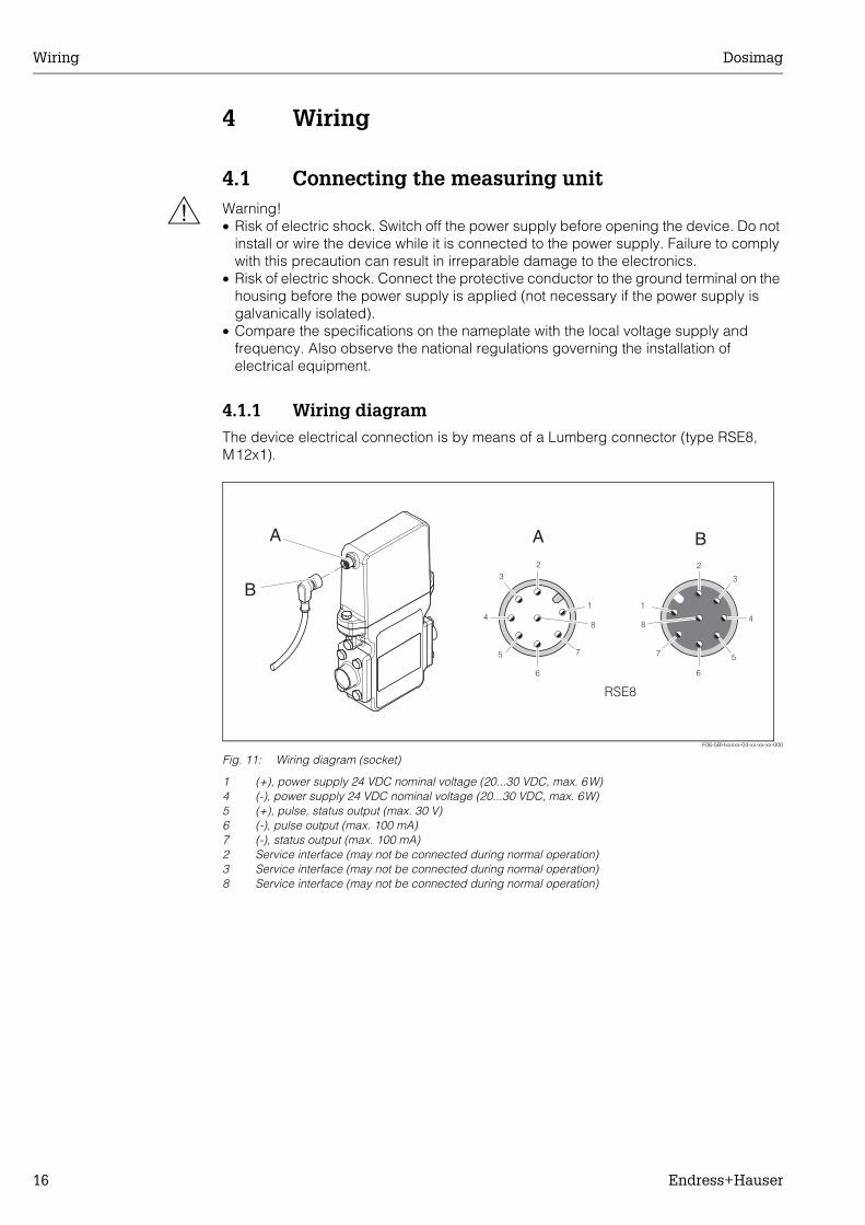
4.1.1 Wiring diagramThe device electrical connection is by means of a Lumberg connector (type RSE8, M12x1).
F06-5BHxxxxx-04-xx-xx-xx-000
Fig. 11: Wiring diagram (socket)
1 (+), power supply 24 VDC nominal voltage (20...30 VDC, max. 6W)4 (-), power supply 24 VDC nominal voltage (20...30 VDC, max. 6W)5 (+), pulse, status output (max. 30 V)6 (-), pulse output (max. 100 mA)7 (-), status output (max. 100 mA)2 Service interface (may not be connected during normal operation)3 Service interface (may not be connected during normal operation)8 Service interface (may not be connected during normal operation)
A
1
23
4
5
6
7
8
1
2
3
4
5
6
7
8
B
RSE8
A
B
Dosimag Wiring
Endress+Hauser 17
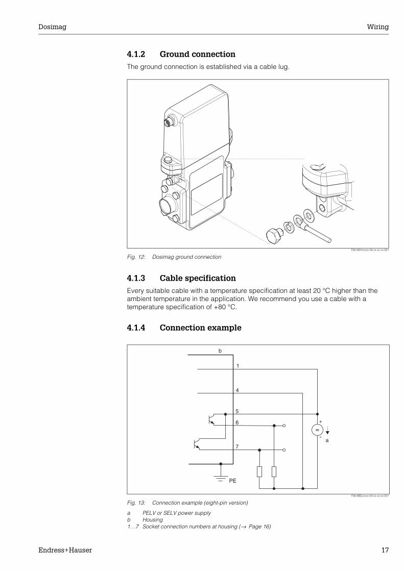
4.1.2 Ground connectionThe ground connection is established via a cable lug.
F06-5BHxxxxx-04-xx-xx-xx-001
Fig. 12: Dosimag ground connection
4.1.3 Cable specificationEvery suitable cable with a temperature specification at least 20 °C higher than the ambient temperature in the application. We recommend you use a cable with a temperature specification of +80 °C.
4.1.4 Connection example
F06-8BExxxxx-04-xx-xx-xx-001
Fig. 13: Connection example (eight-pin version)
a PELV or SELV power supplyb Housing1…7 Socket connection numbers at housing (→ Page 16)
+
-
=
PE
a
1
4
5
6
7
b
Wiring Dosimag
18 Endress+Hauser
4.2 Potential equalisationNo special measures are necessary for potential equalisation.
4.3 Degree of protectionThe devices fulfil all the requirements for IP 67.
Compliance with the following points is mandatory following installation in the field or servicing, in order to ensure that IP 67 protection is maintained:• The housing seals must be clean and undamaged when inserted into their grooves.
The seals must be dried, cleaned or replaced if necessary.• All threaded fasteners and screw covers must be firmly tightened.
4.4 Post-connection checkPerform the following checks after completing electrical installation of the measuring device:
Device condition and specifications Notes
Is the device damaged (visual inspection)? -
Electrical connection Notes
Does the supply voltage match the specifications on the nameplate? 24VDC nominal voltage (20...30VDC)
Do the cables have adequate strain relief? -
Is the housing cover installed and are the fixing screws firmly tightened? -
Dosimag Operation
Endress+Hauser 19
5 Operation
5.1 FieldTool operating programThe Dosimag flow measuring device is operated via the “FieldTool” operating program. FieldTool is a universal service and configuration software package from Endress+Hauser. Connection is by means of the PROline service interface (service connector) with a Commubox FXA 193.
! Note! You can find more information on FieldTool and how it is operated in the appropriate on-line help.
The functionality of FieldTool includes the following:• Configuration of device functions• Visualisation of measuring values (including data logging)• Data backup of device parameters• Measuring-point documentation
Operation Dosimag
20 Endress+Hauser
5.2 Structure of the function matrix
Function group Function
MEASURED VALUES
Page 42⇒
VOLUME FLOW
Page 42
SYSTEM UNITS
Page 43⇒
UNIT OF VOLUME FLOW
Page 43
UNIT OF VOLUME
Page 43
PULSE OUTPUT
Page 44⇒
PULSE VALUE
Page 44
PULSE WIDTH
Page 44
OUTPUT SIGNAL
Page 45
FAILSAFE MODE
Page 45
STATUS OUTPUT
Page 46⇒
ASSIGN STATUS
Page 46
ACTUALSTATUS
Page 46
COMMUNICATION
Page 47⇒
TAG NAME
Page 47
PROCESS PARAMETER
Page 47⇒
ON-VALUE LOW FLOW CUTOFF
Page 47
PRESS. SHOCK SUPPRESSION
Page 48
SYSTEM PARAMETER
Page 49⇒
INSTALL. DIRECT. SENSORPage 49
FLOW DAMPING
Page 49
BINOMIAL FILTER
Page 49
MEDIAN FILTER
Page 49
INTEGRATION TIME
Page 49
SENSOR PARAMETER
Page 50⇒
K-FACTOR POSITIVEPage 50
K-FACTOR NEGATIVEPage 50
ZEROPOINT
Page 50
NOMINAL DIAMETER
Page 50
MEASURING PERIODPage 50
SUPERVISION
Page 51⇒
ACT. SYS. COND.
Page 51
ALARM DELAY
Page 51
SYSTEM RESET
Page 51
PREV. SYS. COND.
Page 51
SIMULATION
Page 52⇒
SIM.MEASURAND
Page 52
VALUE SIM. MEAS.
Page 52
SENSOR VERSION
Page 52⇒
SERIAL NUMBER
Page 52
SENSOR TYPE
Page 52
AMPLIFIER VERSIONPage 52 ⇒
SOFTWARE REV. AMPLIFIER
Page 52
Dosimag Operation
Endress+Hauser 21
5.2.1 General notesThe function matrix comprises a multiplicity of functions which, for the sake of clarity, are arranged in a number of function groups.
! Note! • The transmitter continues to measure while data entry is in progress, i.e. the current
measured values are output via the signal outputs in the normal way.• If the supply voltage fails, all preset and configured values remain safely stored in the
EEPROM or DAT.
" Caution! Changing sensor characteristics influences numerous functions of the entire measuring system, particularly measuring accuracy.Such parameters normally may not be altered and are thus protected. Please contact Endress+Hauser if you have any questions.
Commissioning Dosimag
22 Endress+Hauser
6 Commissioning
6.1 Function checkMake sure that all final checks have been completed before you start up your measuring point:• Checklist for “Post-installation check” → Page 15• Checklist for “Post-connection check” → Page 18
6.2 Switching on the measuring deviceOnce the function checks have been successfully completed, it is time to switch on the supply voltage. The device is now operational.The measuring device performs a number of post switch-on self-tests. Normal measuring mode commences as soon as start-up completes.
! Note! If start-up fails, an error message indicating the cause is displayed in the FieldTool operating program.
Dosimag Maintenance
Endress+Hauser 23
7 MaintenanceNo special maintenance work is required.
Exterior cleaningWhen cleaning the exterior of measuring devices, always use cleaning agents that do not attack the surface of the housing and the seals.
SealsThe seals should be replaced periodically especially if moulded seals are used (aseptic version)! The period between changes depends on the frequency of the cleaning cycles and the fluid and cleaning temperature.Replacement seals (accessory) → Fig. 8
Accessories/spare parts Dosimag
24 Endress+Hauser
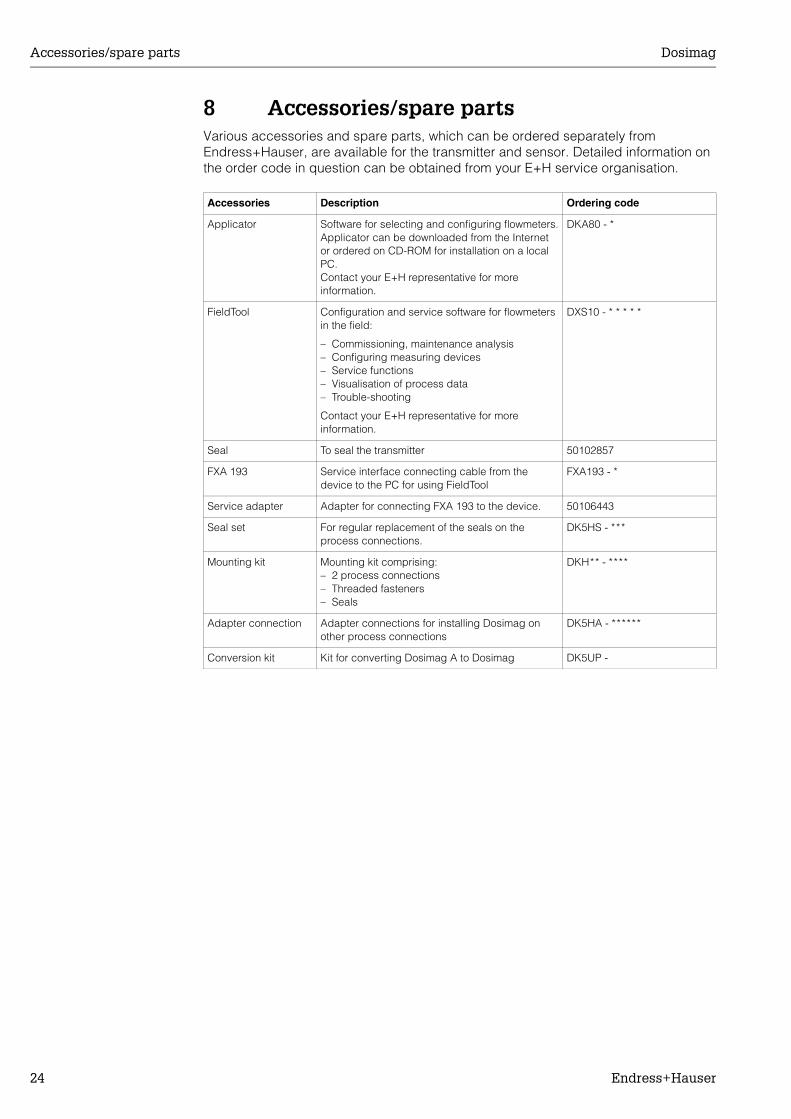
8 Accessories/spare partsVarious accessories and spare parts, which can be ordered separately from Endress+Hauser, are available for the transmitter and sensor. Detailed information on the order code in question can be obtained from your E+H service organisation.
Accessories Description Ordering code
Applicator Software for selecting and configuring flowmeters.Applicator can be downloaded from the Internet or ordered on CD-ROM for installation on a local PC.Contact your E+H representative for more information.
DKA80 - *
FieldTool Configuration and service software for flowmeters in the field:
– Commissioning, maintenance analysis– Configuring measuring devices– Service functions– Visualisation of process data– Trouble-shooting
Contact your E+H representative for more information.
DXS10 - * * * * *
Seal To seal the transmitter 50102857
FXA 193 Service interface connecting cable from the device to the PC for using FieldTool
FXA193 - *
Service adapter Adapter for connecting FXA 193 to the device. 50106443
Seal set For regular replacement of the seals on the process connections.
DK5HS - ***
Mounting kit Mounting kit comprising:– 2 process connections– Threaded fasteners– Seals
DKH** - ****
Adapter connection Adapter connections for installing Dosimag on other process connections
DK5HA - ******
Conversion kit Kit for converting Dosimag A to Dosimag DK5UP -
Dosimag Trouble-shooting
Endress+Hauser 25
9 Trouble-shooting
9.1 Trouble-shooting instructionsFault conditions that arise during operation are immediately identified by Dosimag and signalled and output in different ways:
• Via the status output → Page 28• Via error messages in the "FieldTool" operating program→ Page 26 ff.
9.2 Types of error
9.2.1 Type of errorErrors that occur during commissioning or measuring are signalled and/or displayed immediately. If two or more system or process errors occur, the error with the highest priority is the one shown on the display.
The measuring system distinguishes between two types of error:• System error: This group includes all device errors, for example communication
errors, hardware errors, etc. → Page 26 ff.• Process error: This group includes all application errors → Page 27 ff.
! Note! System and process errors are only differentiated in detail in the FieldTool operating program but not by error signalising via the status output.
9.2.2 Error message typesWhen system/process errors occur, the measuring system also differentiates between and weights fault or notice messages. Serious system errors, e.g. module defects, are always identified and signalled as “fault messages” by the measuring device.
Notice message:• Display:
FieldTool operating program: display via SN or PN (S=System, P=Process, N = Notice)
• The error in question has no impact on the pulse output of the device.
Fault message:• FieldTool operating program: display via SF or PF (S=System, P=Process, F = Fault)• The error in question has a direct impact on the pulse output.
The response of the pulse output can be defined by means of the relevant function in the function matrix → Page 45 ff..
! Note! • A distinction is made between fault and notice messages in the FieldTool operating
program.• For security reasons, error messages should be output via the status output.
Trouble-shooting Dosimag
26 Endress+Hauser
9.3 System error messages (FieldTool)Serious system errors are always recognised by the device as “Fault messages” (SF = System Fault) and displayed appropriately in the FieldTool operating program. Fault messages affect the pulse output provided its failsafe mode is not set to ACTUAL VALUE (→ Page 45).
! Note!
On the other hand, simulations are only classed and displayed as notice messages (SN = System Notice).
" Caution! In the event of a serious fault, a flowmeter might have to be returned to the manufacturer for repair. The procedures on → Page 6 must be carried out before you return the device to Endress+Hauser. Always enclose a duly completed "Declaration of contamination" form. You will find a preprinted form at the back of this manual.
Type No./error message Cause Remedy / spare part
S = System errorF = Fault message (with an impact on the pulse output)N = Notice (without an impact on the pulse output)
System errors - fault messages
SF # 001CRITICAL FAILURE
Serious device error Replace electronics module. Spare parts→ Page 30
SF # 011AMP HW EEPROM
Amplifier:Defective EEPROM
Replace electronics module. Spare parts→ Page 30
SF # 012AMP SW EEPROM
Amplifier:Error accessing EEPROM data
The EEPROM data blocks in which an error has occurred are displayed in the “RESTORE DATA FAILURE” function.Faulty parameters are then replaced by predefined default values.
SF # 031SENSOR HW DAT
Sensor DAT:
1. DAT is defective.
2. DAT is not plugged in or is missing.
1. Replace DAT.Spare parts→ Page 30Check the spare part set number to ensure that the new, replacement DAT is compatible with the measuring electronics.
2. Insert DAT→ Page 31
SF # 032SENSOR SW DAT
Sensor:Error accessing the parameters stored in the DAT.
1. Check whether the DAT is correctly plugged into the electronics board → Page 31.
2. The DAT data blocks in which an error has occurred are displayed in the “RESTORE DATA FAILURE” function.Faulty parameters are then replaced by predefined default values.
3. Replace the DAT if it is defective. Spare parts → Page 30. Before replacing the DAT, check that the new, replacement DAT is compatible with the measuring electronics. Check the:– Spare part set number– Hardware revision code
4. Replace electronics module if necessary.Spare parts→ Page 30
Dosimag Trouble-shooting
Endress+Hauser 27
9.4 Process error messages (FieldTool)
SF # 321TOL. COIL. CURR
Sensor:Coil current is out of tolerance.
– Check contacts between transmitter and sensor.
– Replace sensor or transmitter if necessary.→ Page 31
System errors - notice messages
SF # 359PULSE RANGE
Pulse output:The pulse output frequency is outside the permitted range.
1. Increase the setting for pulse value.and/or
2. Reduce flow
3. Reduce pulse width.
SN # 692SIM. MEASURAND
Simulation of measurand active (volume flow)
Switch off simulation.
Type No./error message Cause Remedy / spare part
P = Process errorF = Fault message (with an impact on the pulse output)N = Notice (without an impact on the pulse output)
PF # 421FLOW RANGE
The volume flow is too high. Reduce flow
Type No./error message Cause Remedy / spare part
Trouble-shooting Dosimag
28 Endress+Hauser
9.5 Process errors without message
9.6 Response of outputs to errors
Symptoms Rectification
Measured-value reading shown on display, even though the fluid is at a standstill and the measuring tube is full.
1. Check the fluid for presence of gas bubbles.
2. Activate the “LOW FLOW CUTOFF” function, i.e. enter or increase the value for the switching point.
The fault cannot be rectified or some other fault not described above has occurred.In these instances, please contact your E+H service organisation.
The following options are available for tackling problems of this nature:
Request the services of an E+H service technicianIf you contact our service organisation to have a service technician sent out, please be ready with the following information:– Brief description of the fault– Nameplate specifications (→ Page 7): Order code and serial
number
Returning devices to E+HThe procedures on Page 6 must be carried out before you return a flowmeter requiring repair or calibration to Endress+Hauser. Always enclose a duly completed “Declaration of contamination” form with the flowmeter. You will find a preprinted “Declaration of contamination” form at the back of this manual.
Replace transmitter electronicsComponents in the measuring electronics defective→ order spare parts → Page 30
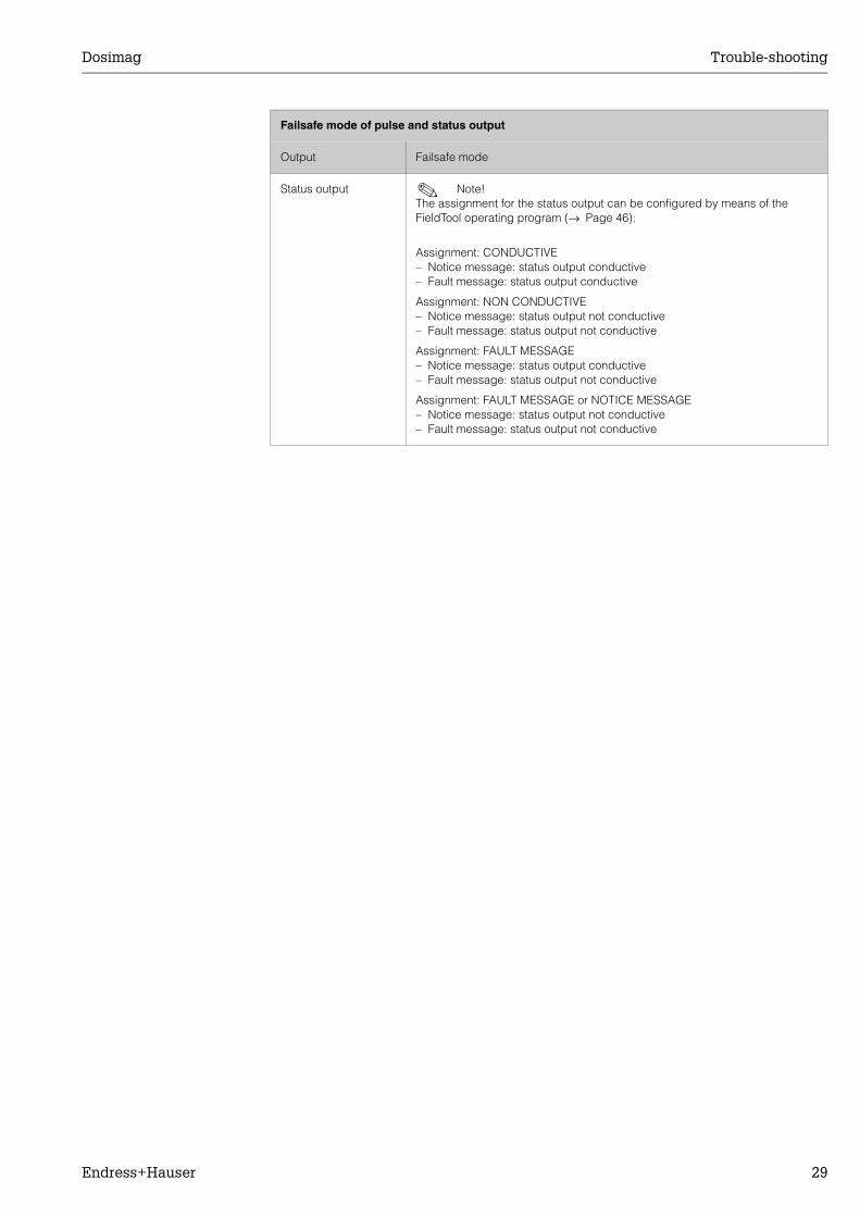
Failsafe mode of pulse and status output
Output Failsafe mode
Pulse output ! Note! The failsafe mode of the pulse output can be configured differently by means of the FieldTool operating program (→ Page 45):
FALLBACK VALUESignal output → no pulses
ACTUAL VALUEFault is ignored, i.e. normal measured-value output on the basis of ongoing flow measurement.
" Caution! System or process errors defined as “Notice messages” have no effect whatsoever on the pulse output. See the information on → Page 25.
Dosimag Trouble-shooting
Endress+Hauser 29
Status output ! Note! The assignment for the status output can be configured by means of the FieldTool operating program (→ Page 46):
Assignment: CONDUCTIVE– Notice message: status output conductive– Fault message: status output conductive
Assignment: NON CONDUCTIVE– Notice message: status output not conductive– Fault message: status output not conductive
Assignment: FAULT MESSAGE– Notice message: status output conductive– Fault message: status output not conductive
Assignment: FAULT MESSAGE or NOTICE MESSAGE– Notice message: status output not conductive– Fault message: status output not conductive
Failsafe mode of pulse and status output
Output Failsafe mode
Trouble-shooting Dosimag
30 Endress+Hauser
9.7 Spare partsSubsection "Trouble-shooting instructions" (→ Page 25) contains a detailed trouble-shooting guide. The measuring device, moreover, provides additional support in the form of continuous self-diagnosis and error messages.Fault rectification can entail replacing defective components with tested spare parts. An overview is provided on → Page 24.
9.7.1 Storage of the replacement electronics modulePack the electronics module with housing in such a way as to protect it reliably against impact for storage and transportation. The original packaging provides optimum protection for this and also helps prevent contamination.
Dosimag Trouble-shooting
Endress+Hauser 31
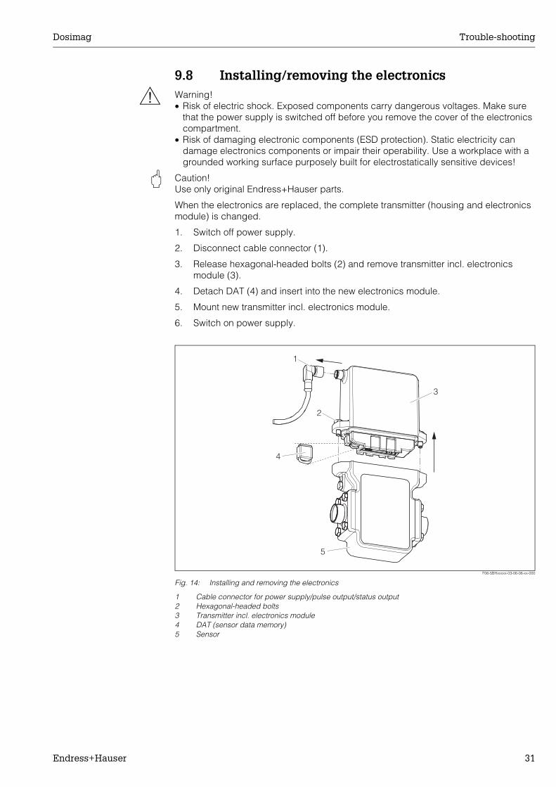
9.8 Installing/removing the electronics
# Warning! • Risk of electric shock. Exposed components carry dangerous voltages. Make sure
that the power supply is switched off before you remove the cover of the electronics compartment.
• Risk of damaging electronic components (ESD protection). Static electricity can damage electronics components or impair their operability. Use a workplace with a grounded working surface purposely built for electrostatically sensitive devices!
" Caution! Use only original Endress+Hauser parts.
When the electronics are replaced, the complete transmitter (housing and electronics module) is changed.
1. Switch off power supply.
2. Disconnect cable connector (1).
3. Release hexagonal-headed bolts (2) and remove transmitter incl. electronics module (3).
4. Detach DAT (4) and insert into the new electronics module.
5. Mount new transmitter incl. electronics module.
6. Switch on power supply.
F06-5BHxxxxx-03-06-06-xx-000
Fig. 14: Installing and removing the electronics
1 Cable connector for power supply/pulse output/status output2 Hexagonal-headed bolts3 Transmitter incl. electronics module4 DAT (sensor data memory)5 Sensor
1
2
3
4
5
Trouble-shooting Dosimag
32 Endress+Hauser
9.9 Software history
9.10 ReturnSee Page 6.
9.11 DisposalPlease observe the regulations applicable in your country or region.
Software version / date Changes to software DocumentationChanges, amendments
V1.00.00/01.12.2003 Original software
Compatible with FieldTool:
-
Dosimag Technical data
Endress+Hauser 33
10 Technical data
10.1 Technical data
10.1.1 ApplicationThe measuring device is used to measure the flow rate of liquids in closed piping systems.A minimum conductivity of 5 µS/cm is required for measuring; the minimum conductivity required in the case of demineralised water is 20 µS/cm.
10.1.2 Function and system design
Measuring principle Electromagnetic flow measurement on the basis of Faraday’s Law.
Measuring system The measuring system is a compact unit consisting of a sensor and transmitter.
10.1.3 Input
Measured variable Flow rate (proportional to induced voltage)
Measuring range Typically v=0.01…10m/s with the specified measuring accuracy
Operable flow range Over 1000:1
10.1.4 Output
Output signal Pulse output:Passive, open emitter, max. 30 VDC / 100 mA, galvanically isolated, pulse value and pulse polarity can be selected, adjustable pulse width (0.04 ms...4 ms).
Signal on alarm Pulse output → failsafe mode can be selectedStatus output → transistor non-conductive in the event of a fault or if the power supply fails
Switching output Status output:Open emitter, max. 30 VDC / 100 mA, galvanically isolated
Low flow cutoff Switch-on point for low flow cutoff selectable.
Galvanic isolation The circuits of the pulse/status output, the communication and power supply are galvanically isolated from one another on the device side.
Technical data Dosimag
34 Endress+Hauser
10.1.5 Power supply
Electrical connections See Page 16 ff.
Supply voltage 24VDC nominal voltage (20...30 VDC)When installing the Dosimag based on the CAN/CSA-C22.2 No. 1010.1-92 safety standard for Canada, the power must be supplied via a SELV power supply with maximum 30 VDC.
Potential equalisation No potential matching is needed for grounded steel lines.
Cable connection Lumberg plug (RSE 8, M12x1) for power supply and signal outputs.
Cable specification Every suitable cable with a temperature specification at least 20 °C higher than the ambient temperature in the application. We recommend you use a cable with a temperature specification of +80 °C.
Power consumption DC: <6 W (incl. sensor)Switch-on current: max. 1.9 A (< 5ms) at 24VDC
Power supply failure At least up to 20ms.:All sensor and measuring point data remain in the DAT.
10.1.6 Performance characteristics
Reference operating conditions
To DIN 19200 and VDI/VDE 2641:• Fluid temperature: +28 °C ± 2 K• Ambient temperature: +22 °C ± 2 K• Warm-up period: 30 minutes
Installation:• Inlet run >10 x DN• Outlet run > 5 x DN• Sensor and transmitter grounded.• Sensor centred relative to the pipe.
Max. measured error Volume flow:± 0.25% o.r. (1...4 m/s)or± 0.5% o.r. ± 1 mm/s (o.r. of reading)or± 5% o.r.
Dosimag Technical data
Endress+Hauser 35
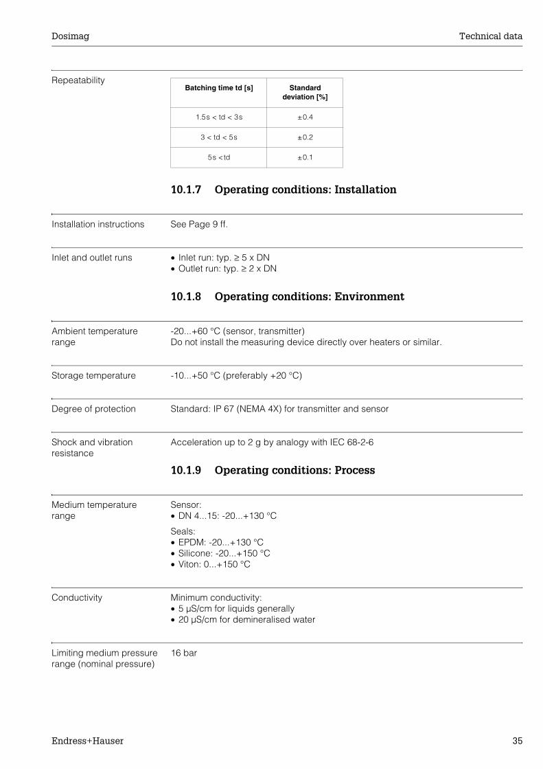
Repeatability
10.1.7 Operating conditions: Installation
Installation instructions See Page 9 ff.
Inlet and outlet runs • Inlet run: typ. ≥ 5 x DN• Outlet run: typ. ≥ 2 x DN
10.1.8 Operating conditions: Environment
Ambient temperature range
-20...+60 °C (sensor, transmitter)Do not install the measuring device directly over heaters or similar.
Storage temperature -10...+50 °C (preferably +20 °C)
Degree of protection Standard: IP 67 (NEMA 4X) for transmitter and sensor
Shock and vibration resistance
Acceleration up to 2 g by analogy with IEC 68-2-6
10.1.9 Operating conditions: Process
Medium temperature range
Sensor:• DN 4...15: -20...+130 °C
Seals:• EPDM: -20...+130 °C• Silicone: -20...+150 °C• Viton: 0...+150 °C
Conductivity Minimum conductivity:• 5 µS/cm for liquids generally• 20 µS/cm for demineralised water
Limiting medium pressure range (nominal pressure)
16 bar
Batching time td [s] Standard deviation [%]
1.5s < td < 3s ±0.4
3 < td < 5s ±0.2
5s <td ±0.1
Technical data Dosimag
36 Endress+Hauser
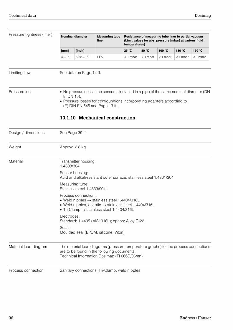
Pressure tightness (liner)
Limiting flow See data on Page 14 ff.
Pressure loss • No pressure loss if the sensor is installed in a pipe of the same nominal diameter (DN 8, DN 15).
• Pressure losses for configurations incorporating adapters according to (E) DIN EN 545 see Page 13 ff..
10.1.10 Mechanical construction
Design / dimensions See Page 39 ff.
Weight Approx. 2.8 kg
Material Transmitter housing:1.4308/304
Sensor housing:Acid and alkali-resistant outer surface; stainless steel 1.4301/304
Measuring tube:Stainless steel 1.4539/904L
Process connection:• Weld nipples → stainless steel 1.4404/316L• Weld nipples, aseptic → stainless steel 1.4404/316L• Tri-Clamp → stainless steel 1.4404/316L
Electrodes:Standard: 1.4435 (AISI 316L); option: Alloy C-22
Seals:Moulded seal (EPDM, silicone, Viton)
Material load diagram The material load diagrams (pressure-temperature graphs) for the process connections are to be found in the following documents:Technical Information Dosimag (TI 066D/06/en)
Process connection Sanitary connections: Tri-Clamp, weld nipples
Nominal diameter Measuring tube liner
Resistance of measuring tube liner to partial vacuum(Limit values for abs. pressure [mbar] at various fluid temperatures)
[mm] [inch] 25 °C 80 °C 100 °C 130 °C 150 °C
4…15 5/32…1/2" PFA < 1 mbar < 1 mbar < 1 mbar < 1 mbar < 1 mbar

Dosimag Technical data
Endress+Hauser 37
10.1.11 User interface
Display elements Dosimag does not have a display or display elements.
Remote operation Operation takes place via the "FieldTool™" configuration and service program from Endress+Hauser. This can be used to configure functions and read off measured values.
10.1.12 Certificates and approvals
Sanitary compatibility 3A approval, EHEDG
Pressure measuring device approval
All Dosimag devices correspond to Article 3(3) of the EC Directive 97/23/EC (Pressure Equipment Directive) and have been designed and manufactured according to good engineering practice.
CE mark The measuring system is in conformity with the statutory requirements of the EC Directives. Endress+Hauser confirms successful testing of the device by affixing to it the CE mark.
Other approvals Additional approvals from the certification bodies FM (USA) and CSA (Canada) are available for all Dosimag devices for use in non-explosion protected atmospheres. Contact your E+H sales office for more information.
Other standards and guidelines
EN 60529:Degrees of protection by housing (IP code)
EN 61010-1:Protection Measures for Electrical Equipment for Measurement, Control, Regulation and Laboratory Procedures.
CSA-C22.2 No. 142-M1987Process Control Equipment
EN 61326 (IEC 1326):Electromagnetic compatibility (EMC requirements)
CAN/CSA-C22.2 No. 1010.1-92Safety requirements for Electrical Equipment for Measuring and Control and Laboratory Use. Pollution degree 2, Installation Category I
ANSI/ISA-S82.01Safety Standard for Electrical and Electronic Test, Measuring, Controlling and related Equipment - General Requirements. Pollution degree 2, Installation Category I
10.1.13 Ordering information
The E+H service organisation can provide detailed ordering information and information on specific order codes on request.

Technical data Dosimag
38 Endress+Hauser
10.1.14 Accessories
Various accessories, which can be ordered separately from E+H, are available for the transmitter and the sensor (→ Page 24 ff.). The E+H service organisation can provide detailed information on request.
10.1.15 Supplementary Documentation
❑Technical Information Dosimag (TI066D/06/en)
Dosimag Technical data
Endress+Hauser 39
10.2 Dimensions
10.2.1 Dosimag dimensions
F06-5BHxxxxx-06-00-xx-xx-000
Fig. 15: Dosimag dimensions
133
100
80
86
90
210
42
33.4
M
DI
12
7050
10
DN PN DI M
DIN[mm]
ANSI[inch]
DIN[bar] [mm] [mm]
4 5/32" 16 4.5 M 6x4
8 5/16" 16 9.0 M 6x4
15 1/2" 16 16.0 M 6x4
Fitting length depends on process connections
Technical data Dosimag
40 Endress+Hauser
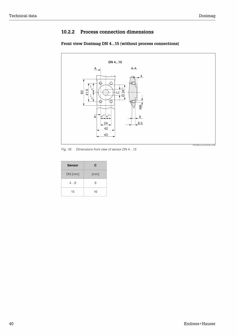
10.2.2 Process connection dimensions
Front view Dosimag DN 4...15 (without process connections)
F06-5BHxxxxx-06-05-08-xx-000
Fig. 16: Dimensions front view of sensor DN 4…15
43
42
6
8.524
=
=
=
=
A
A A-A
4
60 41.6
Ø 3
4
C
M6
-0.1±
0.1
±0.1 ±0.1
±0.
1
0
DN 4...15
Sensor C
DN [mm] [mm]
4…8 9
15 16
Dosimag Technical data
Endress+Hauser 41
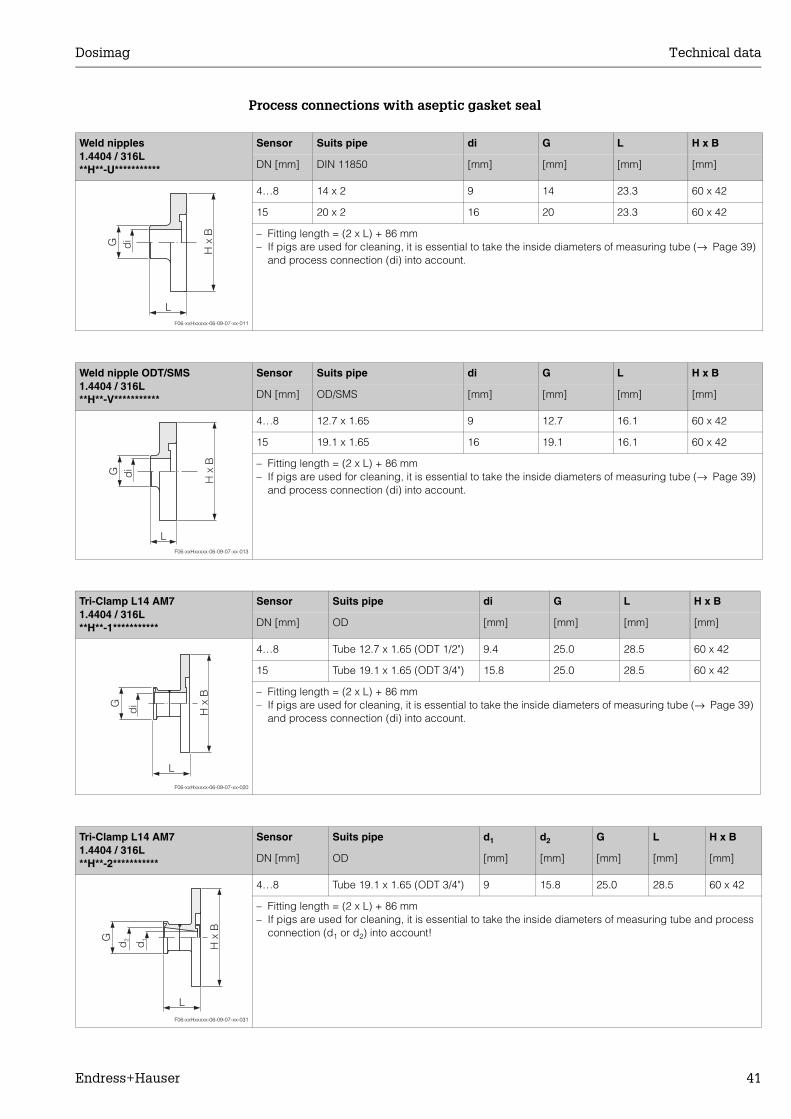
Process connections with aseptic gasket seal
Weld nipples 1.4404 / 316L**H**-U***********
Sensor Suits pipe di G L H x B
DN [mm] DIN 11850 [mm] [mm] [mm] [mm]
F06-xxHxxxxx-06-09-07-xx-011
4…8 14 x 2 9 14 23.3 60 x 42
15 20 x 2 16 20 23.3 60 x 42
– Fitting length = (2 x L) + 86 mm– If pigs are used for cleaning, it is essential to take the inside diameters of measuring tube (→ Page 39)
and process connection (di) into account.
G di
L
H x
B
Weld nipple ODT/SMS1.4404 / 316L**H**-V***********
Sensor Suits pipe di G L H x B
DN [mm] OD/SMS [mm] [mm] [mm] [mm]
F06-xxHxxxxx-06-09-07-xx-013
4…8 12.7 x 1.65 9 12.7 16.1 60 x 42
15 19.1 x 1.65 16 19.1 16.1 60 x 42
– Fitting length = (2 x L) + 86 mm– If pigs are used for cleaning, it is essential to take the inside diameters of measuring tube (→ Page 39)
and process connection (di) into account.
G di
L
H x
B
Tri-Clamp L14 AM71.4404 / 316L**H**-1***********
Sensor Suits pipe di G L H x B
DN [mm] OD [mm] [mm] [mm] [mm]
F06-xxHxxxxx-06-09-07-xx-020
4…8 Tube 12.7 x 1.65 (ODT 1/2") 9.4 25.0 28.5 60 x 42
15 Tube 19.1 x 1.65 (ODT 3/4") 15.8 25.0 28.5 60 x 42
– Fitting length = (2 x L) + 86 mm– If pigs are used for cleaning, it is essential to take the inside diameters of measuring tube (→ Page 39)
and process connection (di) into account.
G
di
L
H x
B
Tri-Clamp L14 AM71.4404 / 316L**H**-2***********
Sensor Suits pipe d1 d2 G L H x B
DN [mm] OD [mm] [mm] [mm] [mm] [mm]
F06-xxHxxxxx-06-09-07-xx-031
4…8 Tube 19.1 x 1.65 (ODT 3/4") 9 15.8 25.0 28.5 60 x 42
– Fitting length = (2 x L) + 86 mm– If pigs are used for cleaning, it is essential to take the inside diameters of measuring tube and process
connection (d1 or d2) into account!G
d2
L
H x
B
d1
Appendix - Function description Dosimag
42 Endress+Hauser
11 Appendix - Function descriptionThis Appendix provides you with a detailed description of, and information on, the individual device functions of Dosimag. All the device functions can be selected and configured via the "FieldTool" configuration program from Endress+Hauser (→ Page 19).Certain values or settings can deviate from the factory settings listed in the case of devices with customer-specific configuration.
11.1 Function group "MEASURING VALUES"
Function group MEASURING VALUES → Page 42Function group SYSTEM UNITS → Page 43Function group PULSE OUTPUT → Page 44Function group STATUS OUTPUT → Page 46Function group COMMUNICATION → Page 47Function group PROCESS PARAMETER → Page 47Function group SYSTEM PARAMETER → Page 49Function group SENSOR PARAMETER → Page 50Function group SUPERVISION → Page 51Function group SIMULATION → Page 52Function group "SENSOR VERSION" → Page 52Function group "AMPLIFIER VERSION" → Page 52
Function descriptionFunction group "MEASURING VALUES"
! Note! • The engineering unit of the measured variables shown here can be set in
the “SYSTEM UNITS" function group (→ Page 43).• If the fluid in the pipe flows backwards, a negative sign prefixes the flow
reading.
VOLUME FLOW The volume flow currently measured appears on the display.
Dosimag Appendix - Function description
Endress+Hauser 43
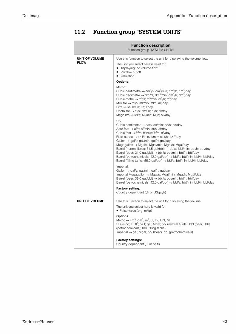
11.2 Function group "SYSTEM UNITS"
Function descriptionFunction group "SYSTEM UNITS"
UNIT OF VOLUME FLOW
Use this function to select the unit for displaying the volume flow.
The unit you select here is valid for:• Displaying the volume flow• Low flow cutoff• Simulation
Options:
Metric:Cubic centimetre → cm3/s; cm3/min; cm3/h; cm3/dayCubic decimetre → dm3/s; dm3/min; dm3/h; dm3/dayCubic metre → m3/s; m3/min; m3/h; m3/dayMillilitre → ml/s; ml/min; ml/h; ml/dayLitre → l/s; l/min; l/h; l/dayHectolitre → hl/s; hl/min; hl/h; hl/dayMegalitre → Ml/s; Ml/min; Ml/h; Ml/day
US:Cubic centimeter → cc/s; cc/min; cc/h; cc/dayAcre foot → af/s; af/min; af/h; af/dayCubic foot → ft3/s; ft3/min; ft3/h; ft3/dayFluid ounce → oz f/s; oz f/min; oz f/h; oz f/dayGallon → gal/s; gal/min; gal/h; gal/dayMegagallon → Mgal/s; Mgal/min; Mgal/h; Mgal/dayBarrel (normal fluids: 31.5 gal/bbl) → bbl/s; bbl/min; bbl/h; bbl/dayBarrel (beer: 31.0 gal/bbl) → bbl/s; bbl/min; bbl/h; bbl/dayBarrel (petrochemicals: 42.0 gal/bbl) → bbl/s; bbl/min; bbl/h; bbl/dayBarrel (filling tanks: 55.0 gal/bbl) → bbl/s; bbl/min; bbl/h; bbl/day
Imperial:Gallon → gal/s; gal/min; gal/h; gal/dayImperial Megagallon → Mgal/s; Mgal/min; Mgal/h; Mgal/dayBarrel (beer: 36.0 gal/bbl) → bbl/s; bbl/min; bbl/h; bbl/dayBarrel (petrochemicals: 42.0 gal/bbl) → bbl/s; bbl/min; bbl/h; bbl/day
Factory setting:Country dependent (l/h or USgal/h)
UNIT OF VOLUME Use this function to select the unit for displaying the volume.
The unit you select here is valid for:• Pulse value (e.g. m3/p)
Options:Metric → cm3; dm3; m3; µl; ml; l; hl; MlUS → cc; af; ft3; oz f; gal; Mgal; bbl (normal fluids); bbl (beer); bbl (petrochemicals); bbl (filling tanks)Imperial → gal; Mgal; bbl (beer); bbl (petrochemicals)
Factory settings:Country dependent (µl or oz fl)
Appendix - Function description Dosimag
44 Endress+Hauser
11.3 Function group "PULSE OUTPUT"
Function descriptionFunction group "PULSE OUTPUT"
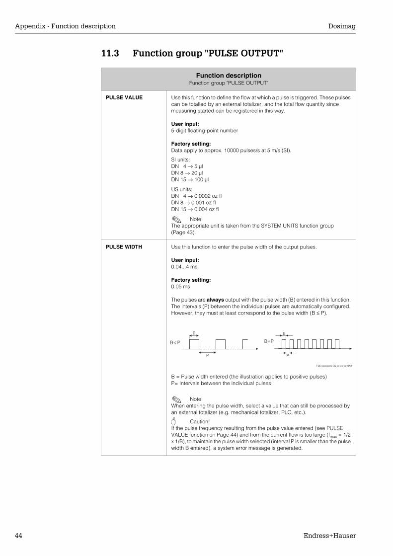
PULSE VALUE Use this function to define the flow at which a pulse is triggered. These pulses can be totalled by an external totalizer, and the total flow quantity since measuring started can be registered in this way.
User input:5-digit floating-point number
Factory setting:Data apply to approx. 10000 pulses/s at 5 m/s (SI).
SI units:DN 4 → 5 µlDN 8 → 20 µlDN 15 → 100 µl
US units:DN 4 → 0.0002 oz flDN 8 → 0.001 oz flDN 15 → 0.004 oz fl
! Note! The appropriate unit is taken from the SYSTEM UNITS function group (Page 43).
PULSE WIDTH Use this function to enter the pulse width of the output pulses.
User input:0.04...4 ms
Factory setting:0.05 ms
The pulses are always output with the pulse width (B) entered in this function. The intervals (P) between the individual pulses are automatically configured. However, they must at least correspond to the pulse width (B ≤ P).
F06-xxxxxxxx-05-xx-xx-xx-012
B = Pulse width entered (the illustration applies to positive pulses)P= Intervals between the individual pulses
! Note! When entering the pulse width, select a value that can still be processed by an external totalizer (e.g. mechanical totalizer, PLC, etc.).
" Caution! If the pulse frequency resulting from the pulse value entered (see PULSE VALUE function on Page 44) and from the current flow is too large (fmax = 1/2 x 1/B), to maintain the pulse width selected (interval P is smaller than the pulse width B entered), a system error message is generated.
B=P
B
PP
B
B< P
Dosimag Appendix - Function description
Endress+Hauser 45
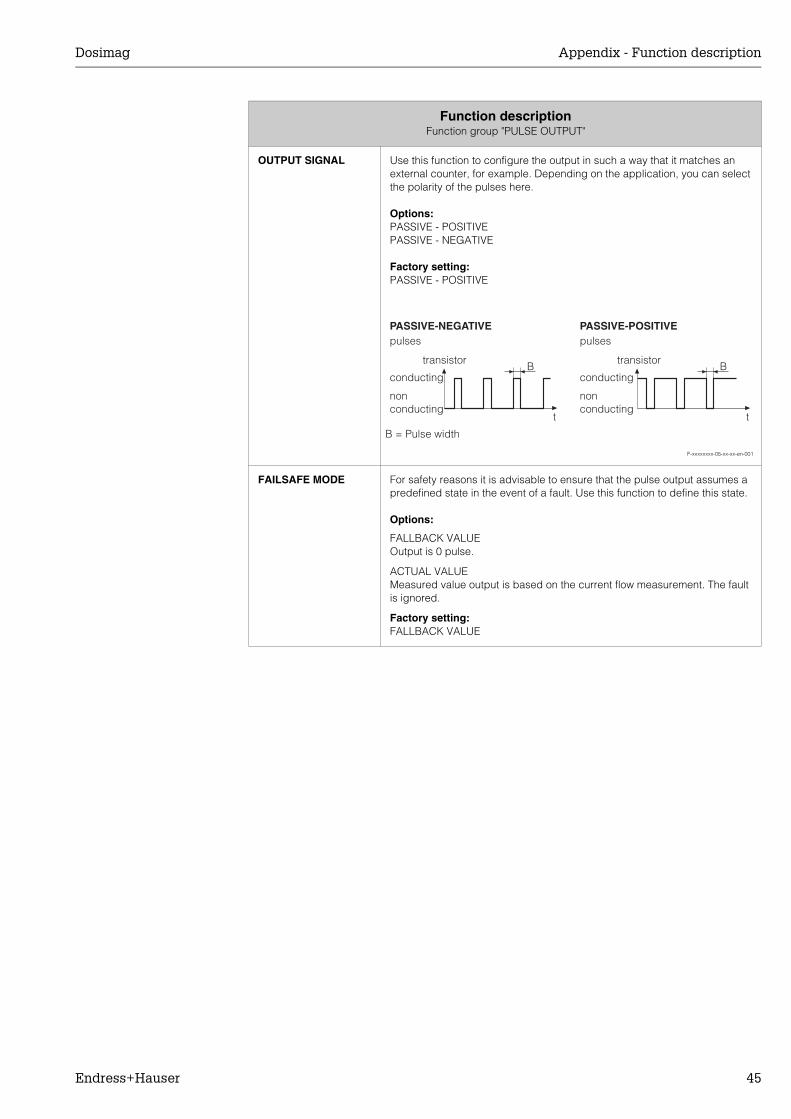
OUTPUT SIGNAL Use this function to configure the output in such a way that it matches an external counter, for example. Depending on the application, you can select the polarity of the pulses here.
Options:PASSIVE - POSITIVEPASSIVE - NEGATIVE
Factory setting:PASSIVE - POSITIVE
F-xxxxxxxx-05-xx-xx-en-001
FAILSAFE MODE For safety reasons it is advisable to ensure that the pulse output assumes a predefined state in the event of a fault. Use this function to define this state.
Options:
FALLBACK VALUEOutput is 0 pulse.
ACTUAL VALUEMeasured value output is based on the current flow measurement. The fault is ignored.
Factory setting:FALLBACK VALUE
Function descriptionFunction group "PULSE OUTPUT"
B B
PASSIVE-POSITIVEpulses
conducting conducting
nonconducting
nonconducting
t t
transistor transistor
PASSIVE-NEGATIVEpulses
B = Pulse width
Appendix - Function description Dosimag
46 Endress+Hauser
11.4 Function group "STATUS OUTPUT"
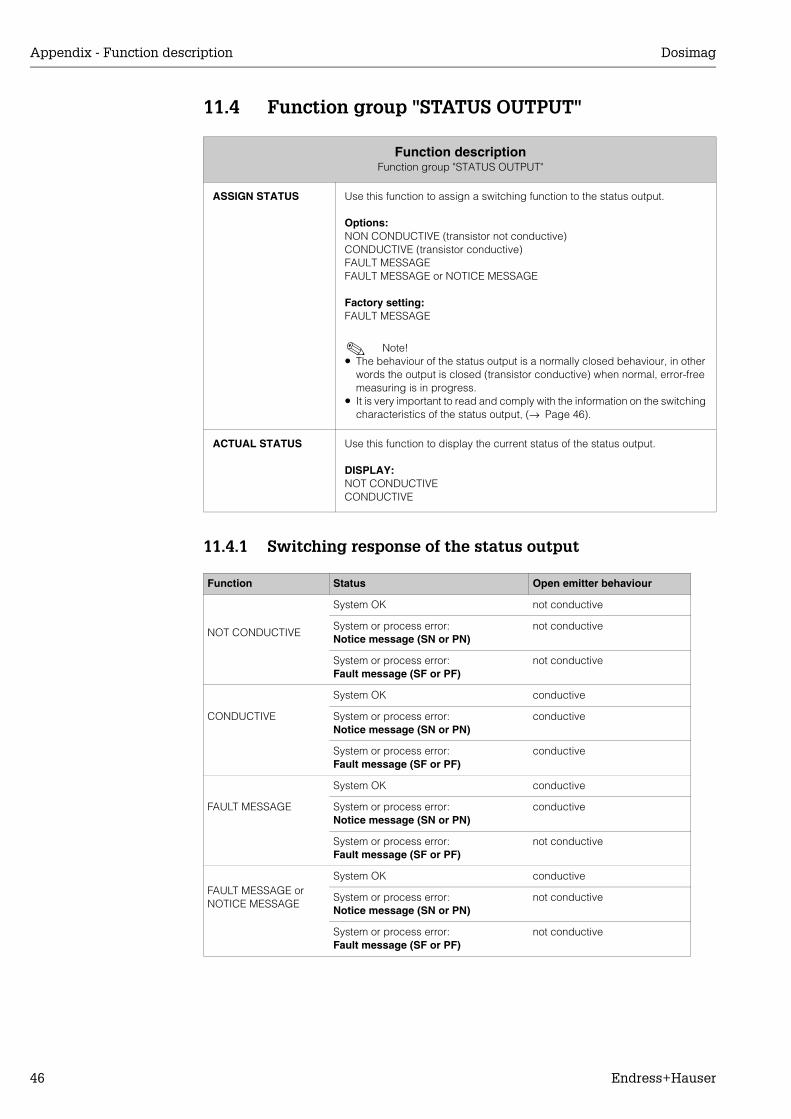
11.4.1 Switching response of the status output
Function descriptionFunction group "STATUS OUTPUT"
ASSIGN STATUS Use this function to assign a switching function to the status output.
Options:NON CONDUCTIVE (transistor not conductive)CONDUCTIVE (transistor conductive)FAULT MESSAGEFAULT MESSAGE or NOTICE MESSAGE
Factory setting:FAULT MESSAGE
! Note! • The behaviour of the status output is a normally closed behaviour, in other
words the output is closed (transistor conductive) when normal, error-free measuring is in progress.
• It is very important to read and comply with the information on the switching characteristics of the status output, (→ Page 46).
ACTUAL STATUS Use this function to display the current status of the status output.
DISPLAY:NOT CONDUCTIVECONDUCTIVE
Function Status Open emitter behaviour
NOT CONDUCTIVE
System OK not conductive
System or process error:Notice message (SN or PN)
not conductive
System or process error:Fault message (SF or PF)
not conductive
CONDUCTIVE
System OK conductive
System or process error:Notice message (SN or PN)
conductive
System or process error:Fault message (SF or PF)
conductive
FAULT MESSAGE
System OK conductive
System or process error:Notice message (SN or PN)
conductive
System or process error:Fault message (SF or PF)
not conductive
FAULT MESSAGE or NOTICE MESSAGE
System OK conductive
System or process error:Notice message (SN or PN)
not conductive
System or process error:Fault message (SF or PF)
not conductive
Dosimag Appendix - Function description
Endress+Hauser 47
11.5 Function group "COMMUNICATION"
11.6 Function group "PROCESS PARAMETER"
Function descriptionFunction group "COMMUNICATION"
TAG NAME Use this function to assign a tag name to the measuring device.
User input:Max. 8-character text, permissible: A-Z, 0-9, +,-, punctuation marks
Factory setting:"_ _ _ _ _ _ _ _" (no text)
Function descriptionFunction group "PROCESS PARAMETER"
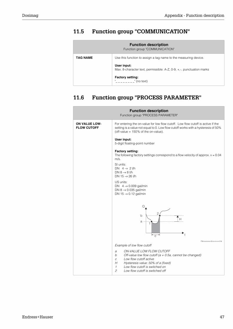
ON VALUE LOW-FLOW CUTOFF
For entering the on-value for low flow cutoff. Low flow cutoff is active if the setting is a value not equal to 0. Low flow cutoff works with a hysteresis of 50% (off-value = 150% of the on-value).
User input:5-digit floating-point number
Factory setting:The following factory settings correspond to a flow velocity of approx. v = 0.04 m/s.
SI units:DN 4 → 2 l/hDN 8 → 8 l/hDN 15 → 26 l/h
US units:DN 4 → 0.009 gal/minDN 8 → 0.035 gal/minDN 15 → 0.12 gal/min
F06-xxxxxxxx-05-xx-xx-xx-016
Example of low flow cutoff
a ON-VALUE LOW FLOW CUTOFFb Off-value low flow cutoff (a + 0.5a, cannot be changed)c Low flow cutoff activeH Hysteresis value: 50% of a (fixed)1 Low flow cutoff is switched on2 Low flow cutoff is switched off
1
c
Q
t
2b
aH
Appendix - Function description Dosimag
48 Endress+Hauser
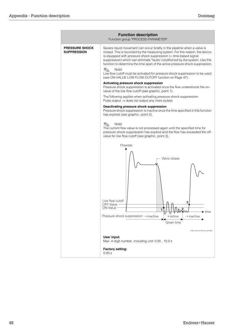
PRESSURE SHOCK SUPPRESSION
Severe liquid movement can occur briefly in the pipeline when a valve is closed. This is recorded by the measuring system. For this reason, the device is equipped with pressure shock suppression (= time-based signal suppression) which can eliminate "faults" conditioned by the system. Use this function to determine the time span of the active pressure shock suppression.
! Note! Low flow cutoff must be activated for pressure shock suppression to be used (see ON-VALUE LOW FLOW CUTOFF function on Page 47).
Activating pressure shock suppressionPressure shock suppression is activated once the flow undershoots the on-value of the low flow cutoff (see graphic, point 1).
The following applies when activating pressure shock suppression:Pulse output → does not output any more pulses
Deactivating pressure shock suppressionPressure shock suppression is inactive once the time specified in this function has expired (see graphic, point 2).
! Note! The current flow value is not processed again until the specified time for pressure shock suppression has expired and the flow has exceeded the off-value for low flow cutoff (see graphic, point 3).
F06-xxxxxxxx-05-xx-xx-en-000
User input:Max. 4-digit number, including unit: 0.00...10.0 s
Factory setting:0.00 s
Function descriptionFunction group "PROCESS PARAMETER"
2
3
➝ active➝ inactive ➝ inactivetime
Low flow cutoff
Pressure shock suppression
OFF-ValueON-Value
Valve closes
Flowrate
1
Given time
Dosimag Appendix - Function description
Endress+Hauser 49
11.7 Function group "SYSTEM PARAMETER"
Function descriptionFunction group "SYSTEM PARAMETER"
INSTALLATION DIRECTION SENSOR
Use this function to reverse the sign of the measured variable, if necessary.
! Note! Ascertain the actual direction of fluid flow with reference to the direction indicated by the arrow on the sensor nameplate.
Options:FORWARDS (flow as indicated by the arrow on the nameplate)REVERSE (flow in the opposite direction to the arrow on the nameplate)
Factory setting:FORWARD
FLOW DAMPING For setting the time constant of flow damping. This can be used to change the reaction time of the measuring system to changes in flow. The reaction time increases with an increasing time constant.
User input:0...100 s
Factory setting:0 s
! Note! The damping acts on all functions and outputs of the measuring device.
BINOMIAL FILTER For setting the filter depth of the digital binomial filter. This can be used to reduce the sensitivity of the measuring system to interference. The reaction time increases with an increasing filter depth.
User input:0…16
Factory setting:4
MEDIAN FILTER Use this function to display the filter depth of the digital median filter. This can be used to reduce the sensitivity of the measuring signal to interference peaks (e.g. in the event of high solids content, gas pockets in the fluid, etc.). The reaction time increases with an increasing filter depth.
User input:0…16
Factory setting:0
INTEGRATION TIME Use this function to display and set the integration time per measuring period. Under normal circumstances it is not necessary to change the factory settings.
! Note! The integration time defines the duration of internal totalling of the induced voltage in the fluid (measured by the measuring electrode), i.e. the time in which the measuring device records the flow (afterwards the magnetic field for the next integration is created from the opposite pole).
Appendix - Function description Dosimag
50 Endress+Hauser
11.8 Function group "SENSOR PARAMETER"
Function descriptionFunction group "SENSOR PARAMETER"
All sensor data, including calibration factor, zero point, nominal diameter, etc. are set at the factory. All the sensor's parameter settings are saved on the DAT memory chip.
K-FACTOR POSITIVE Use this function to display the current calibration factor (positive flow direction) for the sensor. The calibration factor is determined and set at the factory.
Factory setting:Depends on nominal diameter and calibration
K-FACTOR NEGATIVE Use this function to display the current calibration factor (negative flow direction) for the sensor.
Factory setting:Depends on nominal diameter and calibration
ZEROPOINT Use this function to display and enter the current zero-point correction value for the sensor.
Factory setting:Depends on the calibration
NOMINAL DIAMETER Use this function to display the nominal diameter for the sensor.
Factory setting:Depends on the size of the sensor
MEASURING PERIOD Use this function to display and set the time for a full measuring period. The duration of the measuring period is calculated from the rise time of the magnetic field, the brief recovery time and the integration time.Under normal circumstances it is not necessary to change the factory settings.
Dosimag Appendix - Function description
Endress+Hauser 51
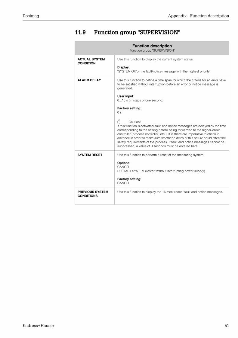
11.9 Function group "SUPERVISION"
Function descriptionFunction group "SUPERVISION"
ACTUAL SYSTEM CONDITION
Use this function to display the current system status.
Display:"SYSTEM OK"or the fault/notice message with the highest priority.
ALARM DELAY Use this function to define a time span for which the criteria for an error have to be satisfied without interruption before an error or notice message is generated.
User input:0...10 s (in steps of one second)
Factory setting:0 s
" Caution! If this function is activated, fault and notice messages are delayed by the time corresponding to the setting before being forwarded to the higher-order controller (process controller, etc.). It is therefore imperative to check in advance in order to make sure whether a delay of this nature could affect the safety requirements of the process. If fault and notice messages cannot be suppressed, a value of 0 seconds must be entered here.
SYSTEM RESET Use this function to perform a reset of the measuring system.
Options:CANCELRESTART SYSTEM (restart without interrupting power supply)
Factory setting:CANCEL
PREVIOUS SYSTEM CONDITIONS
Use this function to display the 16 most recent fault and notice messages.
Appendix - Function description Dosimag
52 Endress+Hauser
11.10 Function group "SIMULATION"
11.11 Function group "SENSOR VERSION"
11.12 Function group "AMPLIFIER VERSION"
Function descriptionFunction group "SIMULATION"
SIMULATION MEASURAND
Use this function to set all outputs to their defined flow-response modes, in order to check whether they respond correctly. During this time, the words "SIMULATION MEASURAND" appear in the operating program.
Options:OFFVOLUME FLOW
Factory setting:OFF
" Caution! • The measuring device cannot be used for measuring while this simulation
is in progress.• The setting is not saved if the power supply fails.
VALUE SIMULATION MEASURAND
! Note! This function is not available unless the SIMULATION MEASURAND function was activated.
Use this function to specify a selectable value (e.g. 720 l/h). This value is used to test downstream devices and the measuring device itself.
User input:5-digit floating-point number
Factory setting:0 l/h
" Caution! The setting is not saved if the power supply fails.
Function descriptionFunction group "SENSOR VERSION"
SERIAL NUMBER Use this function to display the serial number of the device.
SENSOR TYPE Use this function to view the sensor type.
Function descriptionFunction group "AMPLIFIER VERSION"
SOFTWARE REV. AMPLIFIER
Use this function to display the software revision number of the amplifier.
Dosimag Endress+Hauser
Endress+Hauser 53
Index
AAccessories . . . . . . . . . . . . . . . . . . . . . . . . . . . . . . . 24ACTUAL STATUS . . . . . . . . . . . . . . . . . . . . . . . . . . . 46ACTUAL SYSTEM CONDITION . . . . . . . . . . . . . . . . 51Adapters . . . . . . . . . . . . . . . . . . . . . . . . . . . . . . . . . . 13ALARM DELAY . . . . . . . . . . . . . . . . . . . . . . . . . . . . . 51Ambient temperature range . . . . . . . . . . . . . . . . . . . 35AMPLIFIER VERSION (function group). . . . . . . . . . . 52Application . . . . . . . . . . . . . . . . . . . . . . . . . . . . . . . . 33Approvals . . . . . . . . . . . . . . . . . . . . . . . . . . . . . . . 7, 37ASSIGN STATUS. . . . . . . . . . . . . . . . . . . . . . . . . . . . 46
BBrief operating instructions. . . . . . . . . . . . . . . . . . . . . 2
CCable connection . . . . . . . . . . . . . . . . . . . . . . . . . . . 34Cable specification . . . . . . . . . . . . . . . . . . . . . . . . . . 34CE mark . . . . . . . . . . . . . . . . . . . . . . . . . . . . . . . . . . 37Certificates . . . . . . . . . . . . . . . . . . . . . . . . . . . . . . 7, 37Cleaning
Exterior cleaning . . . . . . . . . . . . . . . . . . . . . . . . . 23Commissioning (notes) . . . . . . . . . . . . . . . . . . . . . . . . 5COMMUNICATION (function group) . . . . . . . . . . . . 47Conductivity . . . . . . . . . . . . . . . . . . . . . . . . . . . . . . . 35Connection
See Electrical connection
DDegree of protection. . . . . . . . . . . . . . . . . . . . . . . . . 35Designated use. . . . . . . . . . . . . . . . . . . . . . . . . . . . . . 5Dimensions
device . . . . . . . . . . . . . . . . . . . . . . . . . . . . . . . . . 39Installation conditions . . . . . . . . . . . . . . . . . . . . . . 9Process connections (aseptic gasket seal) . . . . . 41process connections (front view). . . . . . . . . . . . . 40
Disposal . . . . . . . . . . . . . . . . . . . . . . . . . . . . . . . . . . 32
EElectrical connection
Cable specification . . . . . . . . . . . . . . . . . . . . . . . 17Connection examples . . . . . . . . . . . . . . . . . . . . . 17Degree of protection . . . . . . . . . . . . . . . . . . . . . . 18Ground connection . . . . . . . . . . . . . . . . . . . . . . . 17Measuring unit . . . . . . . . . . . . . . . . . . . . . . . . . . . 16Post-connection check (check list) . . . . . . . . . . . 18Potential equalisation. . . . . . . . . . . . . . . . . . . . . . 18Wiring diagram . . . . . . . . . . . . . . . . . . . . . . . . . . 16
Electrical connections. . . . . . . . . . . . . . . . . . . . . . . . 34Electronics (installing). . . . . . . . . . . . . . . . . . . . . . . . 31Error types (system and process errors) . . . . . . . . . 25Exterior cleaning . . . . . . . . . . . . . . . . . . . . . . . . . . . . 23
FFAILSAFE MODE . . . . . . . . . . . . . . . . . . . . . . . . . . . 45FieldTool (configuration and service software). . . . . 24FLOW DAMPING. . . . . . . . . . . . . . . . . . . . . . . . . . . . 49
Flow rate. . . . . . . . . . . . . . . . . . . . . . . . . . . . . . . . . . . 14Function group AMPLIFIER VERSION . . . . . . . . . . . . 52Function group COMMUNICATION. . . . . . . . . . . . . . 47Function group MEASURING VALUES . . . . . . . . . . . 42Function group PROCESS PARAMETER . . . . . . . . . . 47Function group PULSE OUTPUT . . . . . . . . . . . . . . . . 44Function group SENSOR PARAMETER . . . . . . . . 50–51Function group SENSOR VERSION . . . . . . . . . . . . . . 52Function group SIMULATION . . . . . . . . . . . . . . . . . . 52Function group STATUS OUTPUT . . . . . . . . . . . . . . . 46Function group SYSTEM PARAMETER . . . . . . . . . . . 49Function group SYSTEM UNITS. . . . . . . . . . . . . . . . . 43Function matrix (overview) . . . . . . . . . . . . . . . . . . . . . 20
GGalvanic isolation. . . . . . . . . . . . . . . . . . . . . . . . . . . . 33
IIdentification. . . . . . . . . . . . . . . . . . . . . . . . . . . . . . . . . 7Incoming acceptance . . . . . . . . . . . . . . . . . . . . . . . . . 8Inlet and outlet run . . . . . . . . . . . . . . . . . . . . . . . . . . . 12Installation . . . . . . . . . . . . . . . . . . . . . . . . . . . . . . . . . . 8Installation (notes) . . . . . . . . . . . . . . . . . . . . . . . . . . . . 5Installation conditions
Down pipes. . . . . . . . . . . . . . . . . . . . . . . . . . . . . . 10Mounting location . . . . . . . . . . . . . . . . . . . . . . . . . . 9Orientation . . . . . . . . . . . . . . . . . . . . . . . . . . . . . . 11Partially filled pipes. . . . . . . . . . . . . . . . . . . . . . . . 10
INSTALLATION DIRECTION SENSOR. . . . . . . . . . . . 49Installing the electronics . . . . . . . . . . . . . . . . . . . . . . 31
KK- . . . . . . . . . . . . . . . . . . . . . . . . . . . . . . . . . . . . . . . . 50
LLimiting flow . . . . . . . . . . . . . . . . . . . . . . . . . . . . . . . . 36Limiting medium pressure range . . . . . . . . . . . . . . . . 35Low flow cutoff . . . . . . . . . . . . . . . . . . . . . . . . . . . . . . 33
MMaintenance . . . . . . . . . . . . . . . . . . . . . . . . . . . . . . . 23Material . . . . . . . . . . . . . . . . . . . . . . . . . . . . . . . . . . . 36Material load diagram . . . . . . . . . . . . . . . . . . . . . . . . 36Max. measured error . . . . . . . . . . . . . . . . . . . . . . . . . 34Measured variable . . . . . . . . . . . . . . . . . . . . . . . . . . . 33MEASURING PERIOD . . . . . . . . . . . . . . . . . . . . . . . . 50Measuring principle . . . . . . . . . . . . . . . . . . . . . . . . . . 33Measuring range . . . . . . . . . . . . . . . . . . . . . . . . . . . . 33Measuring system . . . . . . . . . . . . . . . . . . . . . . . . . . . 33MEASURING VALUES (function group). . . . . . . . . . . 42Mechanical construction . . . . . . . . . . . . . . . . . . . . . . 36Medium temperature range . . . . . . . . . . . . . . . . . . . . 35
Dosimag Endress+Hauser
54 Endress+Hauser
NNameplate . . . . . . . . . . . . . . . . . . . . . . . . . . . . . . . . . 7Nameplate specifications
Transmitter . . . . . . . . . . . . . . . . . . . . . . . . . . . . . . 7NOMINAL DIAMETER . . . . . . . . . . . . . . . . . . . . . . . 50Nominal diameter . . . . . . . . . . . . . . . . . . . . . . . . . . . 14
OON VALUE LOW- . . . . . . . . . . . . . . . . . . . . . . . . . . . 47Operable flow range . . . . . . . . . . . . . . . . . . . . . . . . 33Operating conditions (Environment) . . . . . . . . . . . . 35Operating conditions (Installation) . . . . . . . . . . . . . . 35Operating conditions (Process) . . . . . . . . . . . . . . . . 35Operation . . . . . . . . . . . . . . . . . . . . . . . . . . . . . . . . . 19Operation (notes) . . . . . . . . . . . . . . . . . . . . . . . . . . . . 5Operational safety . . . . . . . . . . . . . . . . . . . . . . . . . . . 5Order code
Accessories . . . . . . . . . . . . . . . . . . . . . . . . . . . . 24transmitter . . . . . . . . . . . . . . . . . . . . . . . . . . . . . . . 7
Other standards . . . . . . . . . . . . . . . . . . . . . . . . . . . . 37Output . . . . . . . . . . . . . . . . . . . . . . . . . . . . . . . . . . . 33OUTPUT SIGNAL . . . . . . . . . . . . . . . . . . . . . . . . . . . 45Output signal . . . . . . . . . . . . . . . . . . . . . . . . . . . . . . 33
PPerformance characteristics . . . . . . . . . . . . . . . . . . 34
Max. measured error. . . . . . . . . . . . . . . . . . . . . . 34Reference operating conditions . . . . . . . . . . . . . 34Repeatability . . . . . . . . . . . . . . . . . . . . . . . . . . . . 35
Post-installation check . . . . . . . . . . . . . . . . . . . . . . . 15Potential equalisation . . . . . . . . . . . . . . . . . . . . . . . . 34Power consumption . . . . . . . . . . . . . . . . . . . . . . . . . 34Power supply failure. . . . . . . . . . . . . . . . . . . . . . . . . 34Pressure loss . . . . . . . . . . . . . . . . . . . . . . . . . . . . . . 36
Adapters (reducers, expanders) . . . . . . . . . . . . 13Pressure measuring device approval . . . . . . . . . . . 37PRESSURE SHOCK SUPPRESSION . . . . . . . . . . . . 48Pressure tightness . . . . . . . . . . . . . . . . . . . . . . . . . . 36PREVIOUS SYSTEM CONDITIONS . . . . . . . . . . . . . 51Process connection . . . . . . . . . . . . . . . . . . . . . . . . . 36Process error
Definition . . . . . . . . . . . . . . . . . . . . . . . . . . . . . . . 25Process error messages (FieldTool) . . . . . . . . . . . . 27Process errors (without message) . . . . . . . . . . . . . . 28PROCESS PARAMETER (function group) . . . . . . . . 47PULSE OUTPUT (function group) . . . . . . . . . . . . . . 44PULSE VALUE . . . . . . . . . . . . . . . . . . . . . . . . . . . . . 44PULSE WIDTH . . . . . . . . . . . . . . . . . . . . . . . . . . . . . 44
RReference operating conditions. . . . . . . . . . . . . . . . 34Remote operation. . . . . . . . . . . . . . . . . . . . . . . . . . . 37Repeatability . . . . . . . . . . . . . . . . . . . . . . . . . . . . . . 35Return. . . . . . . . . . . . . . . . . . . . . . . . . . . . . . . . . . . . . 6
SSafety icons . . . . . . . . . . . . . . . . . . . . . . . . . . . . . . . . 6Safety instructions . . . . . . . . . . . . . . . . . . . . . . . . . . . 5Sanitary compatibility . . . . . . . . . . . . . . . . . . . . . . . . 37Seals. . . . . . . . . . . . . . . . . . . . . . . . . . . . . . . . . . . . . 23
Sensor installationAdapters . . . . . . . . . . . . . . . . . . . . . . . . . . . . . . . 13
SENSOR PARAMETER (function group) . . . . . . . . . 50SENSOR TYPE . . . . . . . . . . . . . . . . . . . . . . . . . . . . . 52SENSOR VERSION (function group) . . . . . . . . . . . . 52SERIAL NUMBER . . . . . . . . . . . . . . . . . . . . . . . . . . . 52Serial number . . . . . . . . . . . . . . . . . . . . . . . . . . . . . . . 7Shock resistance . . . . . . . . . . . . . . . . . . . . . . . . . . . 35Signal on alarm . . . . . . . . . . . . . . . . . . . . . . . . . . . . 33SIMULATION (function group) . . . . . . . . . . . . . . . . . 52SIMULATION MEASURAND . . . . . . . . . . . . . . . . . . 52Software (history) . . . . . . . . . . . . . . . . . . . . . . . . . . . 32SOFTWARE REV. AMPLIFIER . . . . . . . . . . . . . . . . . 52STATUS OUTPUT (function group) . . . . . . . . . . . . . 46Storage. . . . . . . . . . . . . . . . . . . . . . . . . . . . . . . . . . . . 8Storage temperature . . . . . . . . . . . . . . . . . . . . . . . . 35SUPERVISION (function group) . . . . . . . . . . . . . . . . 51Supply voltage . . . . . . . . . . . . . . . . . . . . . . . . . . . . . 34Switching output. . . . . . . . . . . . . . . . . . . . . . . . . . . . 33System error
Definition . . . . . . . . . . . . . . . . . . . . . . . . . . . . . . . 25System error messages (FieldTool) . . . . . . . . . . . . . 26SYSTEM PARAMETER (function group). . . . . . . . . . 49SYSTEM RESET . . . . . . . . . . . . . . . . . . . . . . . . . . . . 51SYSTEM UNITS (function group) . . . . . . . . . . . . . . . 43
TTAG NAME . . . . . . . . . . . . . . . . . . . . . . . . . . . . . . . . 47Technical data at a glance. . . . . . . . . . . . . . . . . . . . 33Trademarks . . . . . . . . . . . . . . . . . . . . . . . . . . . . . . . . 7Transport . . . . . . . . . . . . . . . . . . . . . . . . . . . . . . . . . . 8Trouble-shooting . . . . . . . . . . . . . . . . . . . . . . . . . . . 25Types of error . . . . . . . . . . . . . . . . . . . . . . . . . . . . . . 25
UUNIT OF VOLUME . . . . . . . . . . . . . . . . . . . . . . . . . . 43UNIT OF VOLUME FLOW. . . . . . . . . . . . . . . . . . . . . 43
VVALUE SIMULATION MEASURAND . . . . . . . . . . . . 52Vibrations . . . . . . . . . . . . . . . . . . . . . . . . . . . . . . . . . 12VOLUME FLOW . . . . . . . . . . . . . . . . . . . . . . . . . . . . 42
WWeight . . . . . . . . . . . . . . . . . . . . . . . . . . . . . . . . . . . 36Wiring
See Electrical connection
ZZEROPOINT . . . . . . . . . . . . . . . . . . . . . . . . . . . . . . . 50
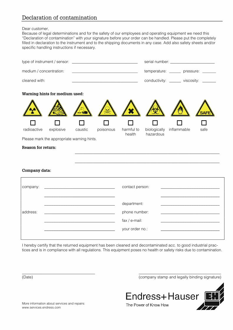
More information about services and repairs:www.services.endress.com
��������������� ����
Dear customer,Because of legal determinations and for the safety of our employees and operating equipment we need this“Declaration of contamination” with your signature before your order can be handled. Please put the completelyfilled in declaration to the instrument and to the shipping documents in any case. Add also safety sheets and/orspecific handling instructions if necessary.
type of instrument / sensor: __________________________________ serial number: _______________________
medium / concentration: __________________________________ temperature: ______ pressure: _______
cleaned with: __________________________________ conductivity: ______ viscosity: _______
���������������� ���� �����
�radioactive
�explosive
�caustic
�poisonous
�harmful to
health
�biologicallyhazardous
�inflammable
�safe
Please mark the appropriate warning hints.
�������������������������������������������������������������������������������������������
���������������������������������������������������������������������������
�� ���������
company: ______________________________ contact person: _________________________
______________________________ _________________________
______________________________ department: _________________________
address: ______________________________ phone number: _________________________
______________________________ fax / e-mail: _________________________
______________________________ your order no.: _________________________
I hereby certify that the returned equipment has been cleaned and decontaminated acc. to good industrial prac-tices and is in compliance with all regulations. This equipment poses no health or safety risks due to contamination.
_______________________________ ___________________________________(Date) (company stamp and legally binding signature)
SAFE
Europe
Austria – Wien❑ Endress+Hauser Ges.m.b.H.Tel. (01) 88 05 60, Fax (01) 88 05 63 35
Belarus – MinskBelorgsintezTel. (017) 2 50 84 73, Fax (017) 2 50 85 83
Belgium / Luxembourg – Bruxelles❑ Endress+Hauser S.A. / N.V.Tel. (02) 2 48 06 00, Fax (02) 2 48 05 53
Bulgaria – SofiaIntertech-Automation Ltd.Tel. (02) 9 62 71 52, Fax (02) 9 62 14 71
Croatia – Zagreb❑ Endress+Hauser GmbH+Co.Tel. (01) 6 63 77 85, Fax (01) 6 63 78 23
Cyprus – NicosiaI+G Electrical Services Co. Ltd.Tel. (02) 48 47 88, Fax (02) 48 46 90
Czech Republic – Praha❑ Endress+Hauser Czech s.r.o.Tel. (02) 66 78 42 00, Fax (026) 66 78 41 79
Denmark – Søborg❑ Endress+Hauser A/STel. (70) 13 11 32, Fax (70) 13 21 33
Estonia – TartuElvi-Aqua OÜTel. (7) 30 27 32, Fax (7) 30 27 31
Finland – Helsinki❑ Metso Endress+Hauser OyTel. (204) 8 31 60, Fax (204) 8 31 61
France – Huningue❑ Endress+Hauser S.A.Tel. (389) 69 67 68, Fax (389) 69 48 02
Germany – Weil am Rhein❑ Endress+Hauser Messtechnik GmbH+Co. KGTel. (07621) 9 75 01, Fax (07621) 97 55 55
Great Britain – Manchester❑ Endress+Hauser Ltd.Tel. (0161) 2 86 50 00, Fax (0161) 9 98 18 41
Greece – AthensI & G Building Services Automation S.A.Tel. (01) 9 24 15 00, Fax (01) 9 22 17 14
Hungary – Budapest❑ Endress+Hauser MagyarországTel. (01) 4 12 04 21, Fax (01) 4 12 04 24
Iceland – ReykjavikSindra-Stál hfTel. 5 75 00 00, Fax 5 75 00 10
Ireland – Clane / County Kildare❑ Flomeaco Endress+Hauser Ltd.Tel. (045) 86 86 15, Fax (045) 86 81 82
Italy – Cernusco s/N, Milano❑ Endress+Hauser S.p.A.Tel. (02) 92 19 21, Fax (02) 92 19 23 62
Latvia – RigaElekoms Ltd.Tel. (07) 33 64 44, Fax (07) 33 64 48
Lithuania – KaunasUAB Agava Ltd.Tel. (03) 7 20 24 10, Fax (03) 7 20 74 14
Macedonia – BeogradMeris d.o.o.Tel. (11) 44 42 96 6, Fax (11) 30 85 77 8
Moldavia – ChisinauS.C. Techno Test SRLTel. (02) 22 61 60, Fax (02) 22 83 13
Netherlands – Naarden❑ Endress+Hauser B.V.Tel. (035) 6 95 86 11, Fax (035) 6 95 88 25
Norway – Lierskogen❑ Endress+Hauser A/STel. 32 85 98 50, Fax 32 85 98 51
Poland – Wroclaw❑ Endress+Hauser Polska Sp. z o.o.Tel. (071) 7 80 37 00, Fax (071) 7 80 37 60
Portugal – Cacem❑ Endress+Hauser Lda.Tel. (21) 4 26 72 90, Fax (21) 4 26 72 99
Romania – BucharestRomconseng S.R.L.Tel. (021) 41 12 50 1, Fax (021) 41 01 63 4
Russia – Moscow❑ Endress+Hauser GmbH+CoTel. (095) 78 32 85 0, Fax (095) 78 32 85 5
Slovak Republic – BratislavaTranscom Technik s.r.o.Tel. (2) 44 88 86 90, Fax (2) 44 88 71 12
Slovenia – Ljubljana❑ Endress+Hauser (Slovenija) D.O.O.Tel. (01) 5 19 22 17, Fax (01) 5 19 22 98
Spain – Sant Just Desvern❑ Endress+Hauser S.A.Tel. (93) 4 80 33 66, Fax (93) 4 73 38 39
Sweden – Sollentuna❑ Endress+Hauser ABTel. (08) 55 51 16 00, Fax (08) 55 51 16 55
Switzerland – Reinach/BL 1❑ Endress+Hauser Metso AGTel. (061) 7 15 75 75, Fax (061) 7 11 16 50
Turkey – Levent/IstanbulIntek Endüstriyel Ölcü ve Kontrol SistemleriTel. (0212) 2 75 13 55, Fax (0212) 2 66 27 75
Ukraine – KievPhotonika GmbHTel. (44) 2 68 81 02, Fax (44) 2 69 07 05
Yugoslavia Republic – BeogradMeris d.o.o.Tel. (11) 4 44 29 66, Fax (11) 3 08 57 78
Africa
Algeria – AnnabaSymes Systemes et MesuresTel. (38) 88 30 03, Fax (38) 88 30 02
Egypt – Heliopolis/CairoAnasia Egypt For Trading (S.A.E.)Tel. (02) 2 68 41 59, Fax (02) 2 68 41 69
Morocco – CasablancaOussama S.A.Tel. (02) 22 24 13 38, Fax (02) 2 40 26 57
Rep. South Africa – Sandton❑ Endress+Hauser (Pty.) Ltd.Tel. (011) 2 62 80 00, Fax (011) 2 62 80 62
Tunisia – TunisCMR Controle, Maintenance et RegulationTel. (07) 17 93 07 7, Fax (07) 17 88 59 5
America
Argentina – Buenos Aires❑ Endress+Hauser Argentina S.A.Tel. (11) 45 22 79 70, Fax (11) 45 22 79 09
Brazil – Sao Paulo❑ Samson Endress+Hauser Ltda.Tel. (011) 50 33 43 33, Fax (011) 50 31 30 67
Canada – Burlington, Ontario❑ Endress+Hauser Canada Ltd.Tel. (905) 68 19 29 2, Fax (905) 68 19 44 4
Chile – Santiago de Chile❑ Endress+Hauser (Chile) Ltd.Tel. (02) 3 21 30 09, Fax (02) 3 21 30 25
Colombia – Bogota D.C.Colsein Ltda.Tel. (01) 2 36 76 59, Fax (01) 6 10 78 68
Costa Rica – San JoseEuro-Tec S.A.Tel. 2 20 28 08, Fax 2 96 15 42
Ecuador – QuitoInsetec Cia. Ltda.Tel. (02) 2 26 91 48, Fax (02) 2 46 18 33
El Salvador – San SalvadorAutomatizacion y Control Industrial de El Salvador, S.A. de C.V.Tel. 2 60 24 24, Fax 2 60 56 77
Guatemala – Ciudad de GuatemalaAutomatizacion y Control Industrial, S.A.Tel. (03) 34 59 85, Fax (03) 32 74 31
Honduras – San Pedro Sula, CortesAutomatizacion y Control Industrial de Honduras, S.A. de C.V.Tel. 5 57 91 36, Fax 5 57 91 39
Mexico – México, D.F❑ Endress+Hauser (México), S.A. de C.V.Tel. (5) 5 55 68 24 07, Fax (5) 5 55 68 74 59
Nicaragua – ManaguaAutomatización y Control Industrial de Nicaragua, S.A.Tel. 2 22 61 90, Fax 2 28 70 24
Peru – MirafloresCorsusa InternationalTel. (1) 44 41 20 0, Fax (1) 44 43 66 4
USA – Greenwood, Indiana❑ Endress+Hauser Inc.Tel. (317) 5 35 71 38, Fax (317) 5 35 84 98
USA – Norcross, Atlanta❑ Endress+Hauser Systems & Gauging Inc.Tel. (770) 4 47 92 02, Fax (770) 4 47 57 67
Venezuela – CaracasControval C.A.Tel. (212) 9 44 09 66, Fax (212) 9 44 45 54
Asia
Azerbaijan – BakuModcon Systems - BakuTel. (12) 92 98 59, Fax (12) 99 13 72
Brunei – Negara Brunei DarussalamAmerican International Industries (B) Sdn. Bhd.Tel. (3) 22 37 37, Fax (3) 22 54 58
Cambodia – Khan Daun Penh, Phom PenhComin Khmere Co. Ltd.Tel. (23) 42 60 56, Fax (23) 42 66 22
China – Shanghai❑ Endress+Hauser (Shanghai) Instrumentation Co. Ltd.Tel. (021) 54 90 23 00, Fax (021) 54 90 23 03
China – Beijing❑ Endress+Hauser (Beijing) Instrumentation Co. Ltd.Tel. (010) 65 88 24 68, Fax (010) 65 88 17 25
Hong Kong – Tsimshatsui / Kowloon❑ Endress+Hauser (H.K.) Ltd.Tel. 8 52 25 28 31 20, Fax 8 52 28 65 41 71
India – Mumbai❑ Endress+Hauser (India) Pvt. Ltd.Tel. (022) 56 93 83 33, Fax (022) 56 93 88 330
Indonesia – JakartaPT Grama BazitaTel. (21) 7 95 50 83, Fax (21) 7 97 50 89
Iran – TehranPatsa IndustryTel. (021) 8 72 68 69, Fax (021) 8 71 96 66
Israel – NetanyaInstrumetrics Industrial Control Ltd.Tel. (09) 8 35 70 90, Fax (09) 8 35 06 19
Japan – Tokyo❑ Sakura Endress Co. Ltd.Tel. (0422) 54 06 11, Fax (0422) 55 02 75
Jordan – AmmanA.P. Parpas Engineering S.A.Tel. (06) 5 53 92 83, Fax (06) 5 53 92 05
Kazakhstan – AlmatyBEI ElectroTel. (72) 30 00 28, Fax (72) 50 71 30
Korea, South – Seoul❑ Endress+Hauser (Korea) Co. Ltd.Tel. (02) 26 58 72 00, Fax (02) 26 59 28 38
Kuwait – SafatUnited Technical Services Est. For General TradingTel. 2 41 12 63, Fax 2 41 15 93
Lebanon – Jbeil Main EntryNetwork EngineeringTel. (3) 94 40 80, Fax (9) 54 80 38
Malaysia – Shah Alam, Selangor Darul Ehsan❑ Endress+Hauser (M) Sdn. Bhd.Tel. (03) 78 46 48 48, Fax (03) 78 46 88 00
Pakistan – KarachiSpeedy AutomationTel. (021) 7 72 29 53, Fax (021) 7 73 68 84
Philippines – Pasig City, Metro Manila❑ Endress+Hauser (Phillipines) Inc.Tel. (2) 6 38 18 71, Fax (2) 6 38 80 42
Saudi Arabia – JeddahAnasia Trading Est.Tel. (02) 6 53 36 61, Fax (02) 6 53 35 04
Singapore – Singapore❑ Endress+Hauser (S.E.A.) Pte. Ltd.Tel. (65) 66 82 22, Fax (65) 66 68 48
Sultanate of Oman – RuwiMustafa & Sultan Sience & Industry Co. L.L.C.Tel. 63 60 00, Fax 60 70 66
Taiwan – TaipeiKingjarl CorporationTel. (02) 27 18 39 38, Fax (02) 27 13 41 90
Thailand – Bangkok 10210❑ Endress+Hauser (Thailand) Ltd.Tel. (2) 9 96 78 11-20, Fax (2) 9 96 78 10
United Arab Emirates – DubaiDescon Trading L.L.C.Tel. (04) 2 65 36 51, Fax (04) 2 65 32 64
Uzbekistan – TashkentIm Mexatronika-TesTel. (71) 1 91 77 07, Fax (71) 1 91 76 94
Vietnam – Ho Chi Minh CityTan Viet Bao Co. Ltd.Tel. (08) 8 33 52 25, Fax (08) 8 33 52 27
Australia + New Zealand
Australia – North Ryde NSW 2113❑ Endress+Hauser Australia Pty. Ltd.Tel. (02) 88 77 70 00, Fax (02) 88 77 70 99
New Zealand – AucklandEMC Industrial Group Ltd.Tel. (09) 4 15 51 10, Fax (09) 4 15 51 15
All other countries❑ Endress+Hauser GmbH+Co. KGInstruments InternationalWeil am Rhein, GermanyTel. (07621) 9 75 02, Fax (07621) 97 53 45
❑ Members of the Endress+Hauser group
http://www.endress.com
05.03
BA 098D/06/en/04.0450107138FM+SGML6.0 ProMoDo