Embed Size (px)
Citation preview
May 19th, 2010 The Joint Advanced Materials and Structures Center of Excellence
May 19th, 2010 The Joint Advanced Materials and Structures Center of Excellence 2
B737-Stabilizer FAA Sponsored Project Information
Principal Investigators & Researchers Dr. John Tomblin Lamia Salah
FAA Technical Monitor Curtis Davies
Other FAA Personnel Involved Larry Ilcewiz Peter Shyprykevich
Industry Participation Dr. Matthew Miller, The Boeing Company Dan Hoffman, Jeff Kollgaard, Karl Nelson, The Boeing Company
May 19th, 2010 The Joint Advanced Materials and Structures Center of Excellence 3
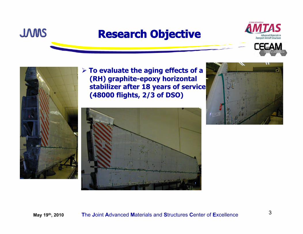
Research Objective
To evaluate the aging effects of a (RH) graphite-epoxy horizontal stabilizer after 18 years of service (48000 flights, 2/3 of DSO)
May 19th, 2010 The Joint Advanced Materials and Structures Center of Excellence 4
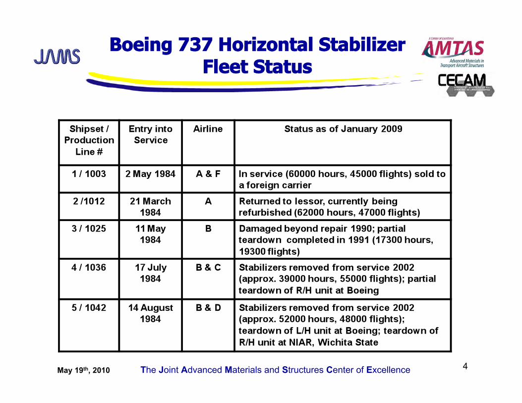
Boeing 737 Horizontal Stabilizer Fleet Status
May 19th, 2010 The Joint Advanced Materials and Structures Center of Excellence 5
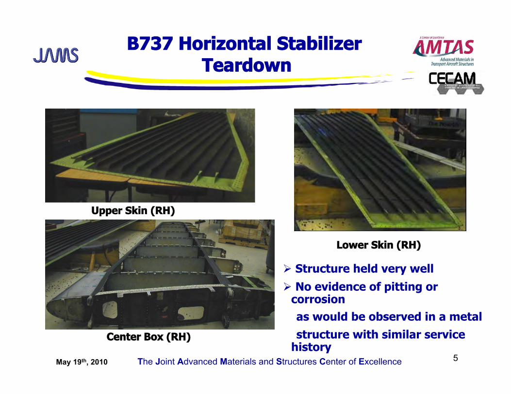
B737 Horizontal Stabilizer Teardown
Upper Skin (RH)
Lower Skin (RH)
Center Box (RH)
Structure held very well
No evidence of pitting or corrosion
as would be observed in a metal
structure with similar service history
May 19th, 2010 The Joint Advanced Materials and Structures Center of Excellence 6
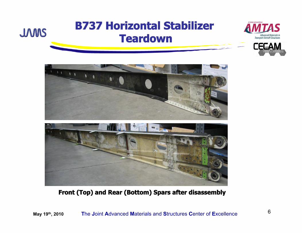
Front (Top) and Rear (Bottom) Spars after disassembly
B737 Horizontal Stabilizer Teardown
May 19th, 2010 The Joint Advanced Materials and Structures Center of Excellence 7
Conclusions Value of the Results
Structure held extremely well after 18 years of service: no obvious signs of aging to the naked eye such as pitting and corrosion as would a metal structure with a similar service history exhibit
Physical tests showed moisture levels in the structure after 18 years of service as predicted during the design phase (1.1 ± 0.1%)
Thermal analysis results very consistent with those obtained for the left hand stabilizer
Thermal analysis showed that the degree of cure of the spars is close to 100%, that additional curing may have occurred in the upper skin due to UV exposure (overall at least 95% cure was achieved in the structure)
Significant improvements in composite manufacturing processes and NDI methods
New material resin system thermal properties comparable to old material but strength is higher (fiber processing improvement)
Teardown provides closure to a very successful NASA program and affirms the viability of composite materials for use in structural components
From all data generated, the margins were sufficient to warrant a “no significant degradation” conclusion.
Project Complete, Final Report Submitted to Technical Monitor
May 19th, 2010 The Joint Advanced Materials and Structures Center of Excellence 8
Beechcraft Starship Aft Wing Teardown- FAA Sponsored Project Information
Principal Investigators & Researchers Dr. John Tomblin Lamia Salah
FAA Technical Monitor Curtis Davies
Other FAA Personnel Involved Larry Ilcewicz Peter Shyprykevich
Industry Participation Mike Mott
May 19th, 2010 The Joint Advanced Materials and Structures Center of Excellence 9
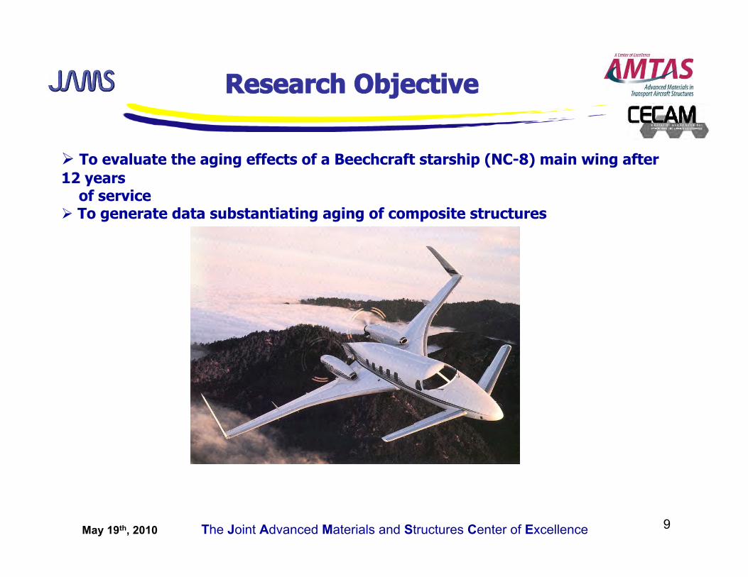
Research Objective
To evaluate the aging effects of a Beechcraft starship (NC-8) main wing after 12 years of service To generate data substantiating aging of composite structures
May 19th, 2010 The Joint Advanced Materials and Structures Center of Excellence 10
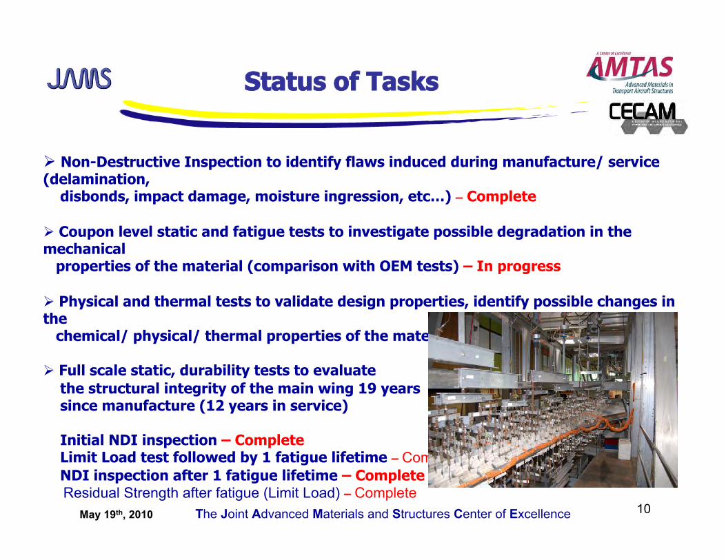
Status of Tasks
Non-Destructive Inspection to identify flaws induced during manufacture/ service (delamination, disbonds, impact damage, moisture ingression, etc…) – Complete
Coupon level static and fatigue tests to investigate possible degradation in the mechanical properties of the material (comparison with OEM tests) – In progress
Physical and thermal tests to validate design properties, identify possible changes in the chemical/ physical/ thermal properties of the material – Complete
Full scale static, durability tests to evaluate the structural integrity of the main wing 19 years since manufacture (12 years in service)
Initial NDI inspection – Complete Limit Load test followed by 1 fatigue lifetime – Complete NDI inspection after 1 fatigue lifetime – Complete Residual Strength after fatigue (Limit Load) – Complete
May 19th, 2010 The Joint Advanced Materials and Structures Center of Excellence 11
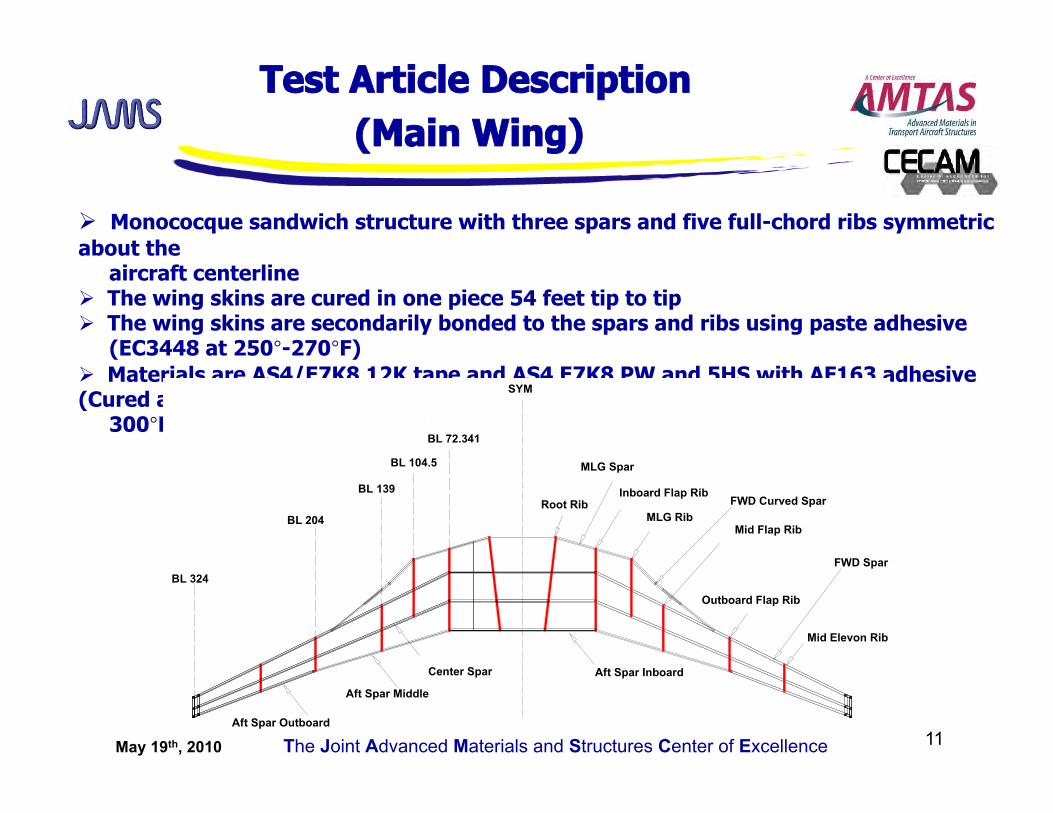
Monococque sandwich structure with three spars and five full-chord ribs symmetric about the aircraft centerline The wing skins are cured in one piece 54 feet tip to tip The wing skins are secondarily bonded to the spars and ribs using paste adhesive (EC3448 at 250°-270°F) Materials are AS4/E7K8 12K tape and AS4 E7K8 PW and 5HS with AF163 adhesive (Cured at 300°F)
Test Article Description (Main Wing)
May 19th, 2010 The Joint Advanced Materials and Structures Center of Excellence 12
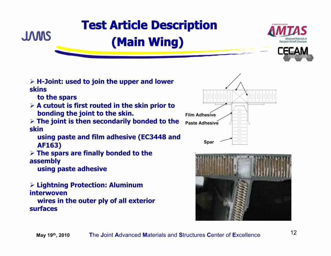
Test Article Description (Main Wing)
H-Joint: used to join the upper and lower skins to the spars A cutout is first routed in the skin prior to bonding the joint to the skin. The joint is then secondarily bonded to the skin using paste and film adhesive (EC3448 and AF163) The spars are finally bonded to the assembly using paste adhesive
Lightning Protection: Aluminum interwoven wires in the outer ply of all exterior surfaces
May 19th, 2010 The Joint Advanced Materials and Structures Center of Excellence 13
Test Article Description (Main Wing)
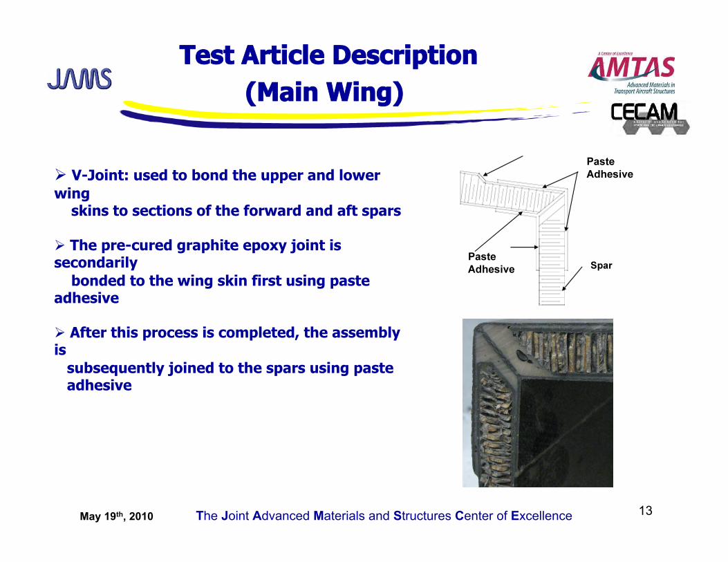
V-Joint: used to bond the upper and lower wing skins to sections of the forward and aft spars
The pre-cured graphite epoxy joint is secondarily bonded to the wing skin first using paste adhesive
After this process is completed, the assembly is subsequently joined to the spars using paste adhesive
May 19th, 2010 The Joint Advanced Materials and Structures Center of Excellence 14
Teardown
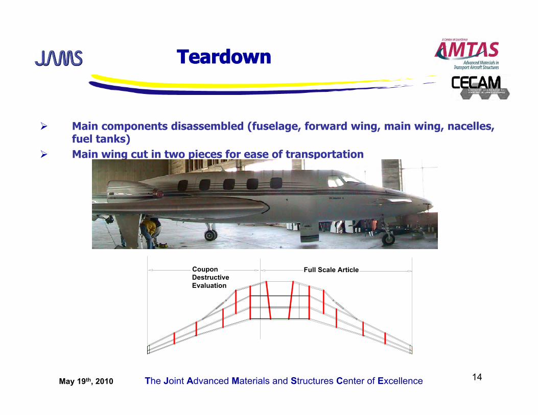
Main components disassembled (fuselage, forward wing, main wing, nacelles, fuel tanks)
Main wing cut in two pieces for ease of transportation
May 19th, 2010 The Joint Advanced Materials and Structures Center of Excellence 15
NDI-LH Main Wing (Skins)
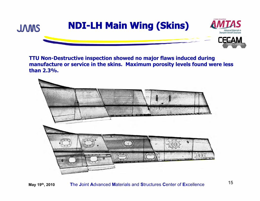
TTU Non-Destructive inspection showed no major flaws induced during manufacture or service in the skins. Maximum porosity levels found were less than 2.3%.
May 19th, 2010 The Joint Advanced Materials and Structures Center of Excellence 16
Thermal Analysis Physical Test Results
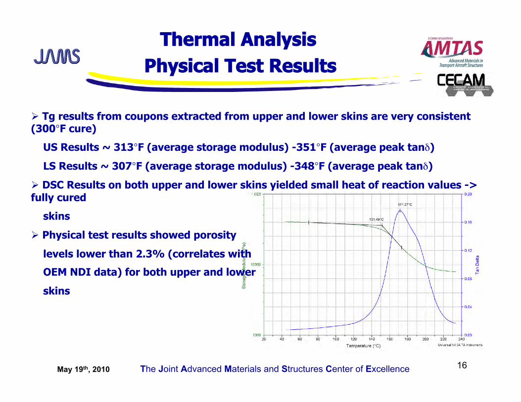
Tg results from coupons extracted from upper and lower skins are very consistent (300°F cure)
US Results ~ 313°F (average storage modulus) -351°F (average peak tanδ)
LS Results ~ 307°F (average storage modulus) -348°F (average peak tanδ)
DSC Results on both upper and lower skins yielded small heat of reaction values -> fully cured
skins
Physical test results showed porosity
levels lower than 2.3% (correlates with
OEM NDI data) for both upper and lower
skins
May 19th, 2010 The Joint Advanced Materials and Structures Center of Excellence 17
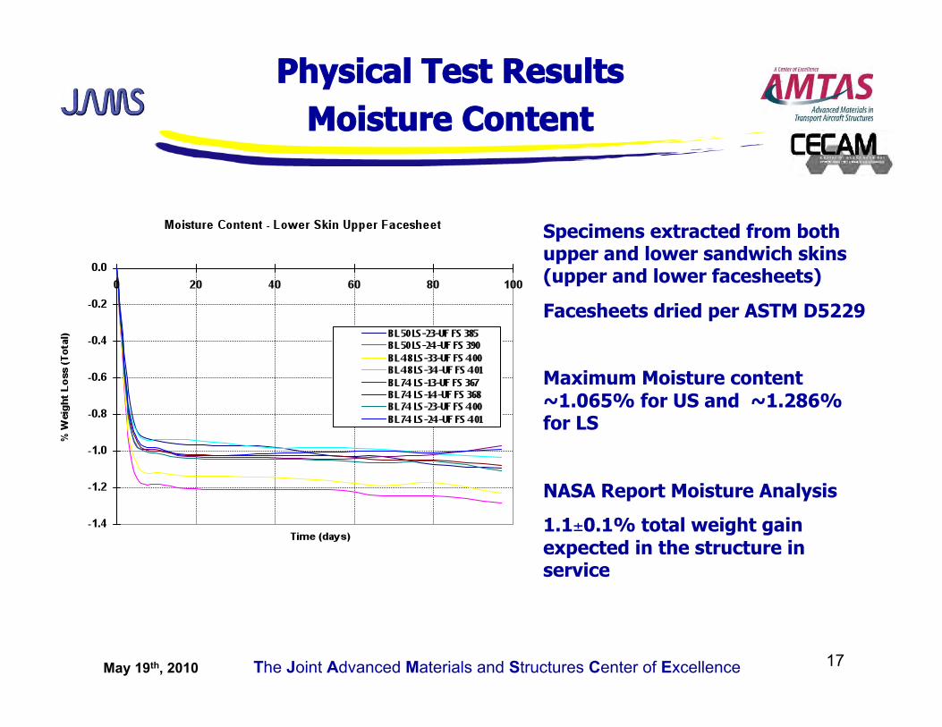
Physical Test Results Moisture Content
Specimens extracted from both upper and lower sandwich skins (upper and lower facesheets)
Facesheets dried per ASTM D5229
Maximum Moisture content ~1.065% for US and ~1.286% for LS
NASA Report Moisture Analysis
1.1±0.1% total weight gain expected in the structure in service
May 19th, 2010 The Joint Advanced Materials and Structures Center of Excellence 18
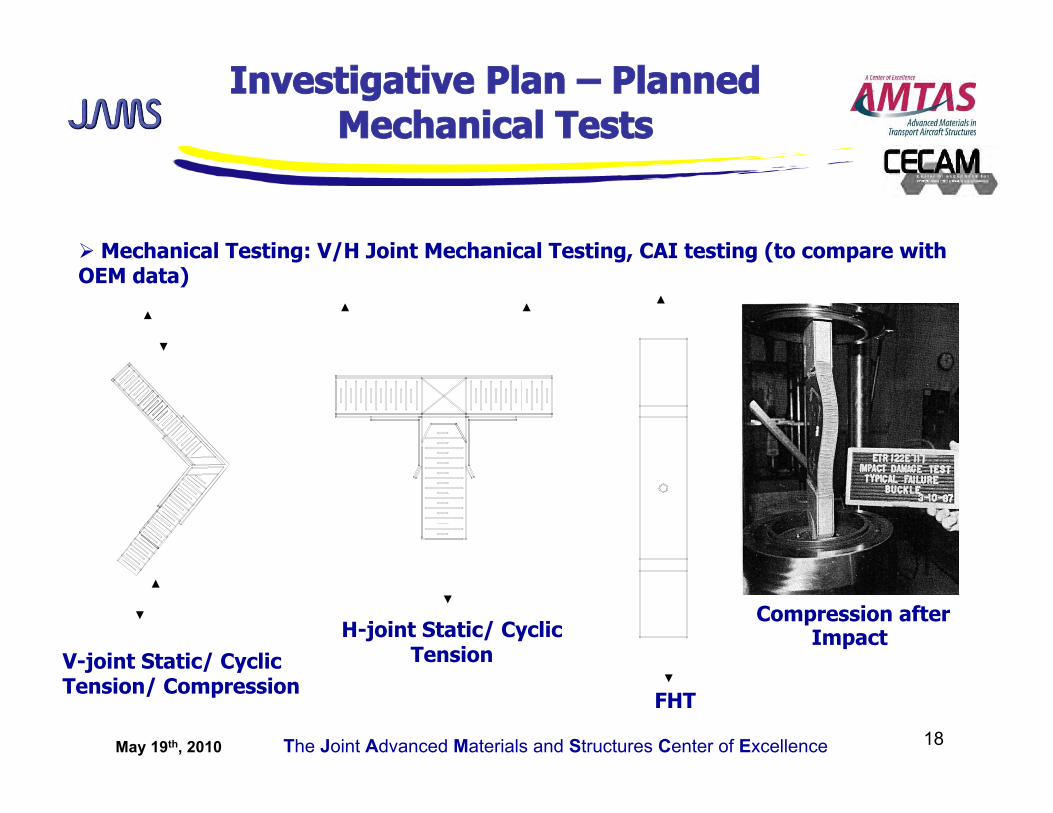
Investigative Plan – Planned Mechanical Tests
Mechanical Testing: V/H Joint Mechanical Testing, CAI testing (to compare with OEM data)
V-joint Static/ Cyclic Tension/ Compression
H-joint Static/ Cyclic Tension
FHT
Compression after Impact
May 19th, 2010 The Joint Advanced Materials and Structures Center of Excellence 19
Methodology
A baseline Non-Destructive Inspection was conducted according to OEM specifications prior to subjecting the structure to limit load (NDI grid has been drawn on the structure for ease of inspection and flaw growth monitoring) Visual inspection, TTU and tap testing were used for the inspection A few areas in both the upper and lower skins have been identified as disbonds by the inspectors ->identified as potted areas-> areas repaired per OEM prior to limit load test
Full Scale Structural Test
Purpose:
unique opportunity to use a production model with service history to validate the component’s (Starship aft wing) structural integrity to test the same structure with the same team that conducted the full scale tests during certification (minimize operator variability) to be able to assess aging effects and estimate the “residual” life of the component using a production article with service history
May 19th, 2010 The Joint Advanced Materials and Structures Center of Excellence 20
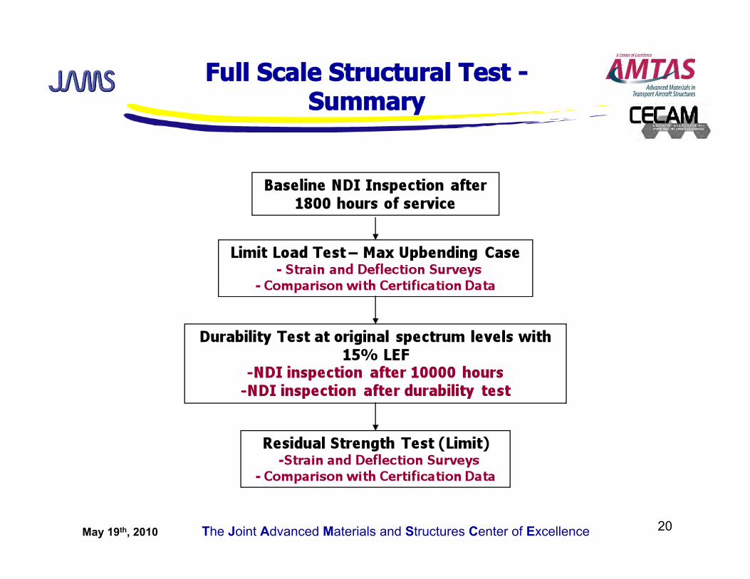
Full Scale Structural Test - Summary
May 19th, 2010 The Joint Advanced Materials and Structures Center of Excellence 21
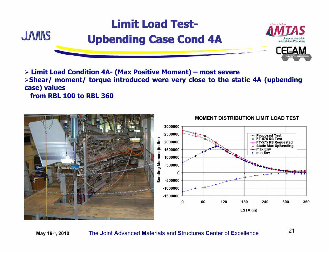
Limit Load Test- Upbending Case Cond 4A
Limit Load Condition 4A- (Max Positive Moment) – most severe Shear/ moment/ torque introduced were very close to the static 4A (upbending case) values from RBL 100 to RBL 360
May 19th, 2010 The Joint Advanced Materials and Structures Center of Excellence 22
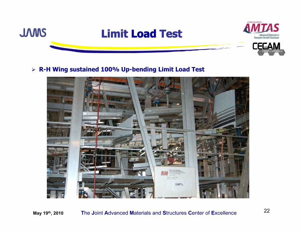
Limit Load Test
R-H Wing sustained 100% Up-bending Limit Load Test
May 19th, 2010 The Joint Advanced Materials and Structures Center of Excellence 23
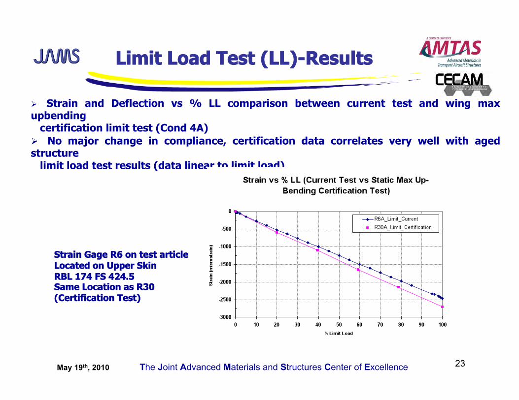
Limit Load Test (LL)-Results
Strain and Deflection vs % LL comparison between current test and wing max upbending certification limit test (Cond 4A) No major change in compliance, certification data correlates very well with aged structure limit load test results (data linear to limit load)
Strain Gage R6 on test article Located on Upper Skin RBL 174 FS 424.5 Same Location as R30 (Certification Test)
May 19th, 2010 The Joint Advanced Materials and Structures Center of Excellence 24
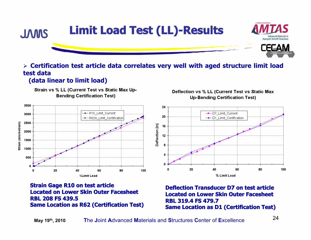
Limit Load Test (LL)-Results
Strain Gage R10 on test article Located on Lower Skin Outer Facesheet RBL 208 FS 439.5 Same Location as R62 (Certification Test)
Deflection Transducer D7 on test article Located on Lower Skin Outer Facesheet RBL 319.4 FS 479.7 Same Location as D1 (Certification Test)
Certification test article data correlates very well with aged structure limit load test data (data linear to limit load)
May 19th, 2010 The Joint Advanced Materials and Structures Center of Excellence 25
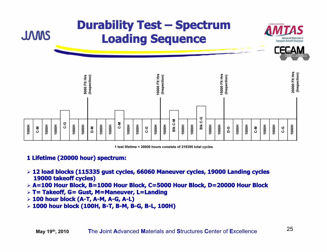
Durability Test – Spectrum Loading Sequence
1 Lifetime (20000 hour) spectrum:
12 load blocks (115335 gust cycles, 66060 Maneuver cycles, 19000 Landing cycles 19000 takeoff cycles) A=100 Hour Block, B=1000 Hour Block, C=5000 Hour Block, D=20000 Hour Block T= Takeoff, G= Gust, M=Maneuver, L=Landing 100 hour block (A-T, A-M, A-G, A-L) 1000 hour block (100H, B-T, B-M, B-G, B-L, 100H)
May 19th, 2010 The Joint Advanced Materials and Structures Center of Excellence 26
Durability Test
full scale durability test to investigate the durability of the aged aft wing
Fatigue loads include gust, maneuver, landing and taxi
fatigue loads applied with 15% LEF
landing loads not included (no landing gear or engines in the structure) (blocks
A-L, B-L)
Test frequency 0.25 hz
Relieving loads were added to the landing gear and engine mount fittings in order
to reduce
the bending moment at the root of the wing (wing box)
Negative loads (upper skin tension loads) truncated
Wing subjected to 200395 cycles of fatigue, 1 lifetime equivalent to 20000
service hours
(19000 takeoff cycles truncated)
Durability test complete
May 19th, 2010 The Joint Advanced Materials and Structures Center of Excellence 27
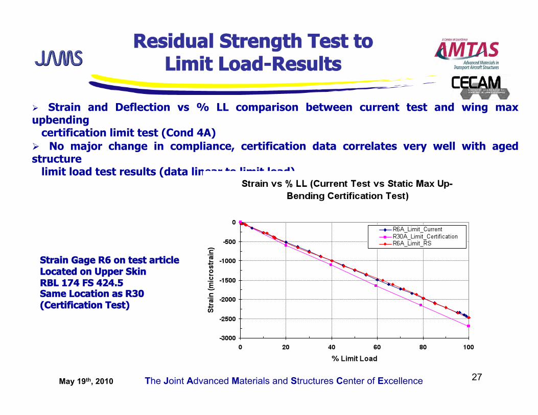
Residual Strength Test to Limit Load-Results
Strain and Deflection vs % LL comparison between current test and wing max upbending certification limit test (Cond 4A) No major change in compliance, certification data correlates very well with aged structure limit load test results (data linear to limit load)
Strain Gage R6 on test article Located on Upper Skin RBL 174 FS 424.5 Same Location as R30 (Certification Test)
May 19th, 2010 The Joint Advanced Materials and Structures Center of Excellence 28
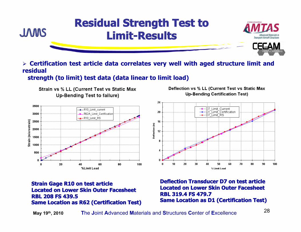
Strain Gage R10 on test article Located on Lower Skin Outer Facesheet RBL 208 FS 439.5 Same Location as R62 (Certification Test)
Deflection Transducer D7 on test article Located on Lower Skin Outer Facesheet RBL 319.4 FS 479.7 Same Location as D1 (Certification Test)
Certification test article data correlates very well with aged structure limit and residual strength (to limit) test data (data linear to limit load)
Residual Strength Test to Limit-Results
May 19th, 2010 The Joint Advanced Materials and Structures Center of Excellence 29
Conclusions
Structure held extremely well after 12 years of service: no obvious signs of aging/ degradation to the naked eye as would a metal structure with a similar service history exhibit
Thermal analysis results show no degradation in thermal properties of the material and that the skins are fully cured/ cross-linked
Physical Tests showed moisture levels indicative of a structure that has reached moisture equilibrium (consistent with other long term service exposure)
Physical test results showed porosity levels higher than 2% which correlate with OEM production information
LH NDI showed no major defects/ damage in the skins introduced during manufacture or service
NDI response subject to operator interpretation (full scale test article inspection)
Full scale test results of the “aged wing” correlated very well with the results obtained for the certification article
May 19th, 2010 The Joint Advanced Materials and Structures Center of Excellence 30
A Look Forward Benefits to Aviation
Understand the aging of composite structures (current aging studies focused on metal structures)
Producibility large co-cured assemblies reduce part and assembly cost, however other
costs should be taken into account, for example, when disposing of non-conforming
assemblies
Supportability needs to be addressed in design. Composite structures must be designed to
be inspectable, maintainable and repairable
most damage to composite structures occurs during assembly or routine aircraft
maintenance
SRM’s are essential to operating with composite structures, engineering information
needed for in-service maintenance and repair
![B737 NG · Boeing B737 NG - Systems Summary [Flight Controls] Page 4 [Option: Blended Winglets] FLIGHT AILERONS LE SLATS SPOILERS GROUND STABILIZER ELEVATORS RUDDER LE FLAPS SPOILERS](https://img.pdfslide.us/doc/110x75/5e58cd14c2964c0a6f59ddd5/b737-ng-boeing-b737-ng-systems-summary-flight-controls-page-4-option-blended.jpg)