Embed Size (px)
Citation preview

B121 FXTCOOLINGTOWER
B123 BENEFITS
B124 CONSTRUCTIONDETAILS
FXT Cooling Tower
B125 CUSTOMFEATURES&OPTIONS
B130 ENGINEERINGDATA
B132 STRUCTURALSUPPORT
T A B L E O F C O N T E N T S
P R O D U C T & A P P L I C A T I O N H A N D B O O K 2 0 1 2 B120

B121 Q U E S T I O N S ? C A L L 4 1 0 . 7 9 9 . 6 2 0 0 O R V I S I T W W W . B A L T I M O R E A I R C O I L . C O M
The FXT was BAC’s first certified tower that features a horizontal design. The FXT delivers performance, maintainability, low initial costs, and incorporates continuous improvements in design that have made it the industry work horse for over 30 years. With low energy consumption and capacities ranging from 58-268 nominal tons, this compact FXT can easily fulfill a wide range of projects with low tonnage requirements.

P R O D U C T & A P P L I C A T I O N H A N D B O O K 2 0 1 2 B122
TheFXT:BAC’sFirstCertifiedTower
CTICertifiedCapacities58to268TonsinaSingleCell
Upto1,155USGPMforProcessApplications
Δ Δ Δ Δ Δ
LowEnergyConsumption
LowInstalled
Costs
5-YearMechanicalEquipmentWarranty
EasytoMaintain
LongService
Life

B123 Q U E S T I O N S ? C A L L 4 1 0 . 7 9 9 . 6 2 0 0 O R V I S I T W W W . B A L T I M O R E A I R C O I L . C O M
FXTBenefits
Easy Access
›› LowEnvironmentalImpact›` ENERGY EFFICIENT
• AllunitsmeetorexceedASHRAEStandard90.1energyefficiencyrequirements
• PremiumefficientVFDcompatiblefanmotors
• HighefficiencyBACross®Fill
• Gravitydistributionwithlowpumpheadrequirements
›› DurableConstruction›` PanelsareconstructedofruggedG-235GalvanizedSteel
›` Forceddraftdesignprotectsmovingparts
›` Variousmaterialsofconstructionareavailabletoenhancelongevityoftheunit(seepage B125fordetails)
›` Coolingtowerduty(TEFC)motorsarebackedbyBAC’s5-yearwarranty
›` HeavydutybearingswithaminimumL10of40,000hours
›› EasyMaintenance›` Thefanmotorislocatedontheexterioroftheunitforeasy
maintenanceandbeltadjustment
›` Standardbasincoverskeepdebrisfromenteringthehotwaterbasin
›` Largegravityorificenozzlespreventcloggingandcaneasilybereplacedwhileunitisinoperation
›` Accessdoorallowsforaccesstotheinterioroftheunit
›` Extendedlubricationlinesminimizemaintenanceofthebearings
›› EasyInstallation›` Singlepiecelift
›` Shipscompletelyassembled,minimizinginstallationtimeandcost
• Nomotorstomount
• Nosheavestoalign
• Nobeltstoinstall
• Nomake-upsystemtoassemble
Single Piece Lift
Premium Efficient Motor

P R O D U C T & A P P L I C A T I O N H A N D B O O K 2 0 1 2 B124
9
2
35
6
14
FXTConstructionDetails
Heavy-DutyConstruction` G-235(Z700metric)hot-dipgalvanizedsteelpanels
FanDriveSystem` V-beltdrive
` Heavy-dutybearingswithaminimumL10of40,000hours(280,000houraveragelife)
` Extendedlubricationlines
` Premiumefficient/inverterdutymotorsasstandard
` 5-yearmotoranddrivewarranty
` LowHPAxialFan(s)
• Highefficiency
• Corrosionresistant
WaterDistributionSystem` Non-clognozzles
` Lowpumpheadgravitydistributionbasin
` Steeldistributioncovers(notshown)
1
2
3
BACross®FillwithIntegralDriftEliminators` Highefficiencyheattransfersurface
` Polyvinylchloride(PVC)
` Impervioustorot,decay,andbiologicalattack
` Flamespreadratingof5perASTME84
AirIntakeScreens` Protectionfrommovingparts
` Easilyremovedforaccesstofans,bearings,motor,anddrives
WaterMake-upValveAssembly` Corrosionresistantfloatvalve
` Largediameterplasticfloat
4
5
6
5YEAR
• WARRANTY •
BAC
MOTOR & DRIVE

B125 Q U E S T I O N S ? C A L L 4 1 0 . 7 9 9 . 6 2 0 0 O R V I S I T W W W . B A L T I M O R E A I R C O I L . C O M
›› MaterialsofConstructionDetermining the appropriate material of construction for a project depends on several factors, including water quality, climate and environmental conditions, availability of time and manpower for maintenance, unit lifetime requirements, and budget. BAC provides the widest variety of material of construction options in the industry and has the ability to provide a solution to meet all conditions and budgets.
›` STANDARD CONSTRUCTION
G-235hot-dipgalvanizedsteelistheheaviestcommerciallyavailablegalvanizedsteel,universallyrecognizedforitsstrengthandcorrosionresistance.Toassurelong-life,G-235hot-dipgalvanizedsteelisusedasthestandardmaterialofconstructionforallunits.Allexposedcutedgesareprotectedwithathickzinccoatingafterfabricationtoensurethethickzinccorrosionbarrierismaintainedforalloverprotection.Withpropermaintenanceandwatertreatment,G-235galvanizedsteelproductswillprovideanexcellentservicelifeundertheoperatingconditionsnormallyencounteredincomfortcoolingandindustrialapplications.
›` THERMOSETTING HYBRID POLYMER
Athermosettinghybridpolymercoating,usedtoextendequipmentlife,isappliedtoselectG-235hot-dipgalvanizedsteelcomponentsoftheunit.Thepolymerizedcoatingisbakedontothegalvanizedsteelandcreatesabarriertothealreadycorrosionresistantgalvanizedsteel.Thethermosettinghybridpolymerhasbeentestedtowithstand6,000hoursina5%saltspraywithoutblistering,chipping,orlossofadhesion.
›` TYPE 304 STAINLESS STEEL COLD WATER BASIN
AType304stainlesssteelcoldwaterbasinisavailable.AllsteelpanelsandstructuralmembersofthecoldwaterbasinareconstructedfromType304stainlesssteel.
FXTCustomFeatures&Options
Standard Construction Installation
Standard Two Fan Construction
Thermosetting Hybrid Polymer
Cust
omer
Valu
ed

P R O D U C T & A P P L I C A T I O N H A N D B O O K 2 0 1 2 B126
›› DriveSystemOptionsThe fan drive system provides the cooling air necessary to reject unwanted heat from the system to the atmosphere. All BAC drive systems use premium efficient cooling tower duty motors and include BAC’s comprehensive 5-year motor and fan drive warranty. Cooling tower duty motors are specially designed for the harsh environment of a cooling tower and have permanently lubricated bearings, drastically decreasing the maintenance requirement of the motor. BAC belt drive systems are the most durable and maintenance friendly drive systems on the market, including single nut adjustment for belt tensioning to make belt tensioning simple.
›` EXTERNAL V-BELT DRIVE
ThisBACengineeredexternaldriveconsistsofaxialfan(s),motor,anddrivesystemlocatedoutsideofthedischargeairstream,protectingthemfrommoisture,condensation,andicing.Thedrivesystemconsistsofspeciallydesignedbelts,taperlocksheaves,andpremiumefficientcoolingtowerdutymotorwithextendedlubricatinglinestoprovidemaximumperformance.ThedrivesystemisbackedbyBAC’scomprehensive5-yearmotorandfandrivewarranty.
›` STANDARD FAN
ThelowsoundlevelsgeneratedandhighefficiencyprovidedbyBAC’sstandardfanmakethemsuitableforinstallationinmostenvironments.
›` EXTENDED LUBRICATION LINES
Extendedlubricationlinesarestandardforlubricationofthefanshaftbearings.Fittingsareextendedtotheoutsideoftheunit.
›` VIBRATION CUTOUT SWITCH (OPTION)
Afactorymountedvibrationcutoutswitchisavailabletoeffectivelyprotectagainstrotatingequipmentfailure.BACcanprovideeitheramechanicalorsolid-stateelectronicvibrationcutoutswitchinaNEMA4enclosuretoensurereliableprotection.Additionalcontactscanbeprovidedoneitherswitchtypetoactivateanalarm.Remoteresetcapabilityisalsoavailableoneitherswitchtype.
External V-Belt Drive
Vibration Cutout Switch
Cust
omer
Valu
ed
5YEAR
• WARRANTY •
BAC
MOTOR & DRIVE

B127 Q U E S T I O N S ? C A L L 4 1 0 . 7 9 9 . 6 2 0 0 O R V I S I T W W W . B A L T I M O R E A I R C O I L . C O M
FXTCustomFeatures&Options
Electric Water Level Control
Easy Access to the Mechanical Water Level Control
›› ShippingandRiggingBAC units are factory-assembled to ensure uniform quality with minimum field assembly. Each unit has been designed to rig in a single piece to minimize installation time.
›` SINGLE PIECE RIGGING
AllsinglecellFXTCoolingTowersshipcompletelyassembled,minimizinginstallationtimeandcost.Therearenomotorstomount,nosheavestoalign,nobeltstoinstall,andnomake-upsystemtoassemble.
›› ColdWaterBasinThe cooling tower water collects in the cold water basin which provides the required head pressure for the cooling system pump.
›` STANDARD MECHANICAL WATER LEVEL CONTROL
Mechanicalmake-upvalvesmustoperatecontinuouslyinthemoistandturbulentenvironmentexistingwithinevaporativecoolingequipment.Duetothisenvironment,theoperationofthevalvemustbesimple,andthevalvemustbedurable.BAC’shighqualitymechanicalwaterlevelcontrolassemblyisstandardwithallunits,andhasbeenspeciallydesignedtoprovidethemostreliableoperationwhilebeingeasytomaintain.Thisaccessoryisomittedforremotesumpapplications.
›` ELECTRIC WATER LEVEL CONTROL (OPTION)
BAC’sElectricWaterLevelControl(EWLC)isastate-of-the-artconductivityactuated,probetypeliquidlevelcontrol.ThehermeticallysealedEWLCisengineeredandmanufacturedspecificallyforuseinevaporativecoolingsystemsandisequippedwithanerrorcodeLEDwhichilluminatestoindicatestatus,includingwhenthewaterand/orprobesaredirty.TheEWLCoptionreplacesthestandardmechanicalmake-upvalve,andincludesaslowclosing,solenoidactivatedvalveinthemake-upwaterlinetominimizewaterhammer.EWLCisrecommendedwhenmoreprecisewaterlevelcontrolisrequiredandinareasthatexperiencesub-freezingconditions.
Cust
omer
Valu
ed
Single Piece Lift

P R O D U C T & A P P L I C A T I O N H A N D B O O K 2 0 1 2 B128
›` BASIN HEATERS (OPTION)
Evaporativecoolingequipmentexposedtobelowfreezingambienttemperaturesrequireprotectiontopreventfreezingofthewaterinthecoldwaterbasinwhentheunitisidle.Factory-installedelectricimmersionheaters,whichmaintain40°F(4.4°C)watertemperature,areasimpleandinexpensivewayofprovidingsuchprotection.
ModelNumber
0°F(-17.8°C)AmbientHeaters -20°F(-28.9°C)AmbientHeaters
NumberofHeaters
kWperHeater
NumberofHeaters
kWperHeater
FXT-26to68 1 3 1 5
FXT-74to95 1 4 1 6
FXT-115to136 2 3 2 5
FXT-160to257 2 4 2 6
H E A T E R K W D A T A
NOTE: This table is based on 460V/3 phase/60 Hz power.
Basin Heater
›› FillBACross® Fill, BAC’s patented crossflow hanging fill, was developed after years of extensive research. BACross® Fill is made of PVC and is optimized to provide the most efficient thermal capacity. PVC is virtually impervious to rot, decay, and biological attack. The fill is elevated above the cold water basin floor to facilitate cleaning and maintenance. The integral eliminators effectively strip entrained moisture from the leaving air stream with minimum pressure drop to prevent water loss with negligible impact on efficiency.
›` STANDARD FILL
BAC’sstandardfillismadeofPVCanddesignedwithmaximizedsurfaceareatogivethemostefficientthermalcapacity.Integraldrifteliminatorsminimizethelossofwaterentrainedintheairstream.PVCisvirtuallyimpervioustorot,decay,andbiologicalattack.Standardfillcanbeusedinapplicationswithenteringwatertemperaturesupto125˚F(51.7°C).Thefillanddrifteliminatorsareformedfromself-extinguishingPVChavingaflamespreadratingof5perASTME84.
Standard Fill
Ships and Rigs in a Single PieceCust
omer
Valu
ed

B129 Q U E S T I O N S ? C A L L 4 1 0 . 7 9 9 . 6 2 0 0 O R V I S I T W W W . B A L T I M O R E A I R C O I L . C O M
FXTCustomFeatures&Options
›` HIGH TEMPERATURE FILL (OPTION)
Anoptionalhightemperaturefillmaterialisavailablewhichincreasesthemaximumallowableenteringwatertemperatureashighas140°F(60.0°C).Thefillanddrifteliminatorsareformedfromself-extinguishingPVChavingaflamespreadratingof5perASTME84.
›› AirIntakeOptionsIn a cooling tower, airborne debris can be entrained in the water through the unit’s air intake. Reducing the amount of debris that enters the tower lowers maintenance requirements and helps to maintain thermal efficiency.
›` AIR INTAKE SCREENS
Thestandard1”x1”wiremeshscreenisfactory-installedtopreventdebrisfromenteringthetower.
›` AIR DISCHARGE SCREENS (OPTION)
1”x1”wiremeshscreensareavailablefactory-installedovertheunitdischargetopreventdebrisfromenteringthedrifteliminatorsandcoldwaterbasin.
Air Intake Screen
FXT Installation

P R O D U C T & A P P L I C A T I O N H A N D B O O K 2 0 1 2 B130
FXTEngineeringData
Model
NumberNominalTonnage MotorHP
Airflow(CFM)
Dimensions Weights(lbs) ConnectionSizes
L W H A Operating Shipping Inlet Outlet
FXT-58 58 3 18,500 6’-1” 7’-4” 7’-4” 1’-5” 3,140 1,220 6” 6”
FXT-68 68 5 21,700 6’-1” 7’-4” 7’-4” 1’-5” 3,150 1,230 6” 6”
FXT-74 74 3 21,800 6’-1” 7’-4” 8’-4” 4’-2” 4,230 1,720 8” 8”
FXT-87 87 5 25,600 6’-1” 7’-4” 8’-4” 4’-2” 4,240 1,730 8” 8”
FXT-95 95 7.5 29,100 6’-1” 7’-8” 8’-4” 4’-2” 4,280 1,770 8” 8”
FXT-115 115 5 33,900 9’-2” 7’-4” 8’-4” 4’-2” 6,080 2,220 8” 8”
FXT-130 130 7.5 38,300 9’-2” 7’-4” 8’-4” 4’-2” 6,120 2,260 8” 8”
FXT-136 136 10 41,800 9’-2” 7’-8” 8’-4” 4’-2” 6,160 2,300 8” 8”
FXT-160 160 7.5 47,100 12’-1” 7’-4” 8’-4” 4’-2” 8,030 2,880 8” 8”
FXT-175 175 10 51,500 12’-1” 7’-4” 8’-4” 4’-2” 8,070 2,920 8” 8”
FXT-192 192 15 58,900 12’-1” 7’-8” 8’-4” 4’-2” 8,120 2,970 8” 8”
FXT-216 216 10 56,400 12’-1” 7’-4” 11’-0” 3’-8” 9,420 3,560 8” 8”
FXT-240 240 15 65,300 12’-1” 7’-8” 11’-0” 3’-8” 9,470 3,610 8” 8”
FXT-257 257 20 70,000 12’-1” 7’-8” 11’-0” 3’-8” 9,490 3,630 8” 8”
NOTES:
1. Unless otherwise indicated, all connections 4” and smaller are MPT and connections 6” and larger are beveled for welding.
2. Operating weight is based on the water level in cold water basin at overflow height.
3. Nominal tons of cooling represents the capability to cool 3 USGPM of water from a 95°F entering water temperature to an 85°F leaving water
temperature at a 78°F entering wet-bulb temperature.
ACCESS
OUTLET
MAKEUP
OVERFLOW
DRAINM
L/2
L2 1/2"
A
H
W
5'-2 1/2"
Models FXT-58 and 68
Do not use for construction. Refer to factory certified dimensions. This catalog includes data current at
the time of publication, which should be reconfirmed at the time of purchase.

B131 Q U E S T I O N S ? C A L L 4 1 0 . 7 9 9 . 6 2 0 0 O R V I S I T W W W . B A L T I M O R E A I R C O I L . C O M
Models FXT 74-136
Models FXT 160-257
Models FXT 74-257
A
H
Q W
*Double Eliminators Standard On Select Models
Access
Outlet
Makeup
Overflow
Drain
M
L/2
L2 1/2"
6'-0"
L2 1/2"
M
7/8”
Nozzles
FlowDivider
FXTEngineeringData
Flow Divider
P R O D U C T & A P P L I C A T I O N H A N D B O O K 2 0 1 2 B132
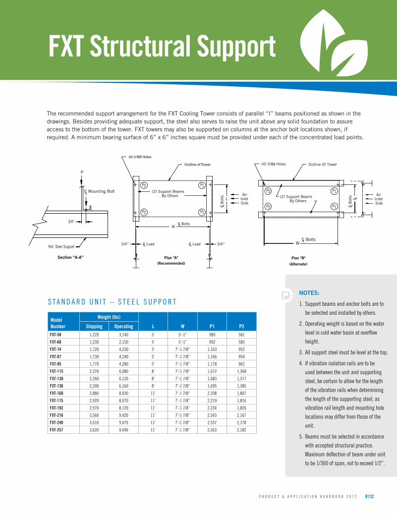
FXTStructuralSupport
TherecommendedsupportarrangementfortheFXTCoolingTowerconsistsofparallel“I”beamspositionedasshowninthedrawings.Besidesprovidingadequatesupport,thesteelalsoservestoraisetheunitaboveanysolidfoundationtoassureaccesstothebottomofthetower.FXTtowersmayalsobesupportedoncolumnsattheanchorboltlocationsshown,ifrequired.Aminimumbearingsurfaceof6”x6”inchessquaremustbeprovidedundereachoftheconcentratedloadpoints.
NOTES:
1. Support beams and anchor bolts are to
be selected and installed by others.
2. Operating weight is based on the water
level in cold water basin at overflow
height.
3. All support steel must be level at the top.
4. If vibration isolation rails are to be
used between the unit and supporting
steel, be certain to allow for the length
of the vibration rails when determining
the length of the supporting steel, as
vibration rail length and mounting hole
locations may differ from those of the
unit.
5. Beams must be selected in accordance
with accepted structural practice.
Maximum deflection of beam under unit
to be 1/360 of span, not to exceed 1/2”.
S T A N D A R D U N I T – S T E E L S U P P O R T
ModelNumber
Weight(lbs)
L W P1 P2Shipping Operating
FXT-58 1,220 3,140 5’ 5’-1” 989 581
FXT-68 1,230 2,150 5’ 5’-1” 992 583
FXT-74 1,720 4,230 5’ 7’-1 7/8” 1,163 952
FXT-87 1,730 4,240 5’ 7’-1 7/8” 1,166 954
FXT-95 1,770 4,280 5’ 7’-1 7/8” 1,178 962
FXT-115 2,220 6,080 8’ 7’-1 7/8” 1,672 1,368
FXT-130 2,260 6,120 8’ 7’-1 7/8” 1,683 1,377
FXT-136 2,300 6,160 8’ 7’-1 7/8” 1,695 1,385
FXT-160 2,880 8,030 11’ 7’-1 7/8” 2,208 1,807
FXT-175 2,920 8,070 11’ 7’-1 7/8” 2,219 1,816
FXT-192 2,970 8,120 11’ 7’-1 7/8” 2,234 1,826
FXT-216 3,560 9,420 11’ 7’-1 7/8” 2,543 2,167
FXT-240 3,610 9,470 11’ 7’-1 7/8” 2,557 2,178
FXT-257 3,630 9,490 11’ 7’-1 7/8” 2,563 2,182
C Load3/4” L L 3/4”C Load
WC BoltsL
L
LC B
olts
(4) 5/8Ø Holes
Outline of Tower
(2) Support BeamsBy Others
P2 P1
P1P2
Plan "A" (Recommended)
AirInletSide Side
InletAir
(Alternate)
Plan "B"
2P 1P
1P
By Others(2) Support Beams
Outline Of Tower(4) 5/8ø Holes
C B
olts
LL
LC BoltsW
P2
P
C Mounting Bolt L
Ref. Steel Support
3/4"
Section “A-A”