Embed Size (px)
Citation preview

BASIC MECHANICAL ENGINEERING
Unit-1 part-1
Thermodynamics

BASIC CONCEPTS OF THERMODYNAMICS
The term Thermodynamics is derived from the Greek words ‘Thermic’ which means Heat and ‘Dynamics’ which means Force.
Thermodynamics is the science that deals with the relationship of heat and mechanical energy and conversion of one into the other.
Eg: Human body, solar heaters, sun, iron box etc.. TD began in 19th Century to exploit the motive power of heat – the capacity of
hot bodies to provide work. The study of TD is based on two general laws of nature, the First law and the
second law of TD. First Law : Heat and work are two mutually convertible forms of energy. Heat never flows on its own from an object at low temperature to an object at
higher temperature, this statement is basis for the second law. Second Law : Heat energy of the source cannot be converted continuously to
work but part of it has to be rejected to sink at lower temperature.

MICROSCOPIC & MACROSCOPIC ANALYSISBehavior of matter can be studied in two viewpoints:
Microscopic Analysis : Behavior of individual atoms or molecules. Behavior of gas is described by summing up behavior of each molecule (Statistical Thermodynamics).
Eg: Study of Atomic Structure in nuclear physics.
Macroscopic Analysis : Behavior of more number of molecules is taken into account. It is also known as Engineering Thermodynamics.
Eg : Force on a given area can be measured by Pressure gauge, Measurement of pressure, volume and temperature.

WORKING SUBSTANCES: Conversion of heat energy in to work and vice-versa takes place through the agency called working substances.
PHASE: A quantity of matter, homogenous in chemical composition and physical structure, is called a Phase.
PURE SUBSTANCE: A pure substance is the one that has a homogeneous and invariable chemical composition even though there is change in phase.Eg: Steam or water or a mixture of steam and water.
HOMOGENEOUS: A system which consists of a single Phase. Eg: Air and water vapour.
HETEROGENEOUS: A system which consists of two or more phases. Eg: Ice and water, water and oil.

SYSTEM: A system is a finite quantity of matter or prescribed region of space.BOUNDARY: It is a real or imaginary envelope enclosing a system.SURROUNDINGS: Everything external to the system.UNIVERSE: System and its surroundings together comprise a system.There are three types of System:•Closed System•Open System•Isolated System
•A closed system can exchange energy, but not mass, with its surroundings. Eg: Piston-cylinder•An open system can exchange both mass and energy with its surroundings. Eg: Air Compressor.•An isolated system cannot exchange mass or energy with its surroundings. Eg- Universe, Flask…. etc….

THERMODYNAMIC PROPERTIES, PROCESSES AND CYCLES
STATE: It is defined as condition of the system at a point.
PROPERTIES: It is defines as the characteristics of the system. (OR) A property is any observable or measurable characteristics of a substance. Eg:- Mass, volume, density, pressure, temperatures, height, width, etc……
TYPES OF PROPERTIES: 3Types: Intensive, Extensive and Specific Property.
INTENSIVE PROPERTY: This type of Property doesn’t depends on mass. Eg:- Pressure, Temperature, Density, Sp. Volume, Sp. Entropy, Area, Velocity,
Viscosity….etc…..
EXTENSIVE PROPERTY: This type of Property depends on mass. Eg:- Volume, Energy, Entropy, Weight….etc………
SPECIFIC PROPERTY: The Extensive property per unit mass is called as specific properties.
Eg:- Sp. Volume, Sp. Gravity, Sp. Energy, Sp. Density….etc…….

PROCESS Change in state (OR) A process occurs whenever a system changes from one state to
another state (OR) When a system changes from one equilibrium state to another
equilibrium state, it is said to have undergone a process. No System can be in true equilibrium during the process, since
the properties are changing. The continuous series of equilibrium states through which the
system passes for reaching from initial state to final state is known as PATH. So, when a path is completely specified, it is called as process.
Types: Reversible Process and
Irreversible Process

QUASI-STATIC PROCESS Quasi-static process is one that takes place so slowly that the
system may be considered as passing through a succession of equilibrium states.
This process may be represented by a path (or line) on the equation of state surface.
For non-quasi-static, only the end-points can be shown.
REVERSIBLE PROCESS:- The system of the surrounding restore to their original state. (OR) A process is reversible if the system is in thermal equilibrium at
all states.(OR) In other words, a process is reversible, when the initial state
together with all energies transformed during the process can be completely restored in both system and surroundings.

REVERSIBLE PROCESS
It is also called Quasi-static process. A Quasi-static Process is one which can be stopped at any state and
reversed, so that the system and surroundings are exactly restore to their initial states.
The process has following characteristics:- It must pass through the same states on the reversed path as were initially
visited on the forward path. It must pass through a continuous series of equilibrium states. The process must be free from friction (internal and mechanical friction) Working fluid should be ideal There should be no heat transfer across a finite temperature difference. At the end of the process, both system and surrounds should reach to the
initial state.
Eg: Elastic deformation, isothermal expansion (or) compression, expansion and compression of spring.

IRREVERSIBLE PROCESS:-
A process is irreversible when the system passes through a sequence of non-equilibrium states at which the process will not have a unique value.
An irreversible process is one in which heat is transferred to a finite temperature or finite gradient.
The irreversible process are represented by a broken line and the end states are assumed to be in equilibrium.
It is irreversible as the surroundings will not reach the initial state accordingly.
Eg: fluid flow in a pipe, combustion of air and fuel, diffusion of gases, free expansion….etc….
THERMODYNAMIC CYCLE:
Cycle is defined as series of process whose end states should be identical.

EQUILIBRIUM
A system is said to be in equilibrium if it does not tend to undergo any change. (OR)
A system is said to be in thermal equilibrium if the temperature and pressure at all points are same.
Systems under temperature and pressure equilibrium but not under chemical equilibrium are said to be in meta-stable equilibrium condition.
STAGES OF EQUILIBRIUM: Mechanical equilibrium Chemical equilibrium Thermal equilibrium and Thermodynamic equilibrium.

MECHANICAL EQUILIBRIUM:For a system to be in mechanical equilibrium there should be any pressure unbalancing either in the interior of the system or between the system and the surroundings.
CHEMICAL EQUILIBRIUM:For a system to be in chemical equilibrium there should be equality of chemical potential, i.e., there should not be any chemical reactions.
THERMAL EQUILIBRIUM:For a system to be in thermal equilibrium there should not be any temperature gradient in the system.For a system to be in thermal equilibrium it is not necessary that the system should be in mechanical and chemical equilibrium.
THERMODYNAMIC EQUILIBRIUM:When a system satisfies the conditions of mechanical equilibrium, chemical equilibrium and thermal equilibrium, it is said to be in a state of thermodynamic equilibrium.

POINT FUNCTION:When two properties locate a point on the graph (coordinate axis) then those properties are called as Point Function.Eg: Pressure, temperature, volume, etc..
PATH FUNCTION:There are certain quantities which cannot be located on a graph by a point but are given by the area under the process. Such quantities are called path functions.Eg: Work and Heat.
HEAT:It is defined as the form of energy that is transferred between two systems due to temperature difference between them.The transfer of heat in to the system is called heat addition (+ve) and heat out a system is called heat rejection (-ve).
WORK:Work is defined as energy expanded by a force through a displacement .The work transferred in to the system is indicated by (-ve sign) and the work output by a system is indicated by (+ ve sign). W = F.S

HEAT & WORK Similarities between work and heat:
• Boundary Phenomenon
• Both are Path Functions
• Both are interchangeable
• Both are inexact differentials and hence are not thermodynamic properties.
Differences between work and heat :
• There cannot be reversible work transfer but there is no restriction for transfer of heat.
• For transfer of heat, temperature difference is needed.
• Sign Convection is +ve for Qin and Wout
-ve for Qout and Win

PDV WORK OR DISPLACEMENT WORK

Displacement work (pdVwork)
Force exerted, F= p. A
Work done dW= F.dL= p. A dL= p.dV
If the piston moves through a finite distance say 1-2,Then work done has to be evaluated by integrating δW=∫pdV

TEMPERATURE: It is an intensive thermodynamic property related to the “hotness” or “coldness” of a body measured on a definite scale.Eg: Thermometer.
ADIABATIC PROCESS:A process in which no heat crosses the boundary of the system is called an adiabatic process.
A wall which is impermeable to the flow of heat is an adiabatic wall, where as a wall which permits the flow of heat is a diathermic wall.

ZEROTH LAW OF THERMODYNAMICS:
When a body ‘A’ is in thermal equilibrium with body ‘B’ and also separately with body ‘C’ then B and C will be in thermal equilibrium with each other.
If two systems are in thermal equilibrium with a third system, they must be in thermal equilibrium with each other.”

PROPERTIES OF IDEAL GASES:
• A gas is a substance which cannot be liquefied by application of pressure at constant temperature.
• A vapour is a gaseous substance which can be liquefied by applying pressure at constant temperature.
• The laws of perfect gas does not apply to vapour. Substance like air, dry or superheated steam are treated as gas.
Boyle’s Law:
Boyle’s Law states that when any gas is heated at constant temperature, the pressure and volume of the gas are inversely proportional.
Charle’s Law:
Charle’s law states that when any gas is heated at constant pressure, its change in volume varies directly with the absolute temperature change.

FIRST LAW OF THERMODYNAMICS Law of conservation of energy. First law of TD: “During any cycle that a closed system undergoes, the
net work transfer is equal to the net heat transfer.” Specific Heat. Joule’s Law:
Joules law states that “ The internal energy of a perfect gas is a function of the absolute temperature.”
Relation ship between two specific heats. Enthalpy:
Sum of internal energy and pressure volume product (pv) is called Enthalpy (h).
h=u+pv Ratio of specific heats

APPLICATION OF FIRST LAW OF TD TO CLOSED SYSTEM OR NON-FLOW SYSTEMi) Reversible constant volume or Isochoric process.
ii) Reversible constant Pressure or Isobaric Process.
iii) Reversible constant Temperature or Isothermal Process.
iv) Reversible Adiabatic Process or Isentropic Process.
PERPETUAL MOTION MACHINE OF FIRST KIND OR PMM1o There can be no machine which would continuously supply
mechanical work without some form of energy disappearing simultaneously such a fictitious machine is called a perpetual motion machine of first kind or PMM1.
o The converse of is also true, that there can be no machine which would continuously consume work without some other form of energy appearing simultaneously.

FLOW PROCESS (OPEN SYSTEM) In flow process there is continuous flow of mass and energy in and
out of the system. Eg: flow of air, gas through a compressor, flow of fluid through a pipe, etc..
Flow process is classified as : 1) Steady flow process
2) unsteady flow process STEADY FLOW PROCESS: Flow rate of mass and energy
doesn’t vary with time. UNSTEADY FLOW PROCESS: Flow rate of mass and energy
vary with time.
STEADY FLOW ENERGY EQUATION (S.F.E.E)
LIMITATIONS OF THE FIRST LAW OF THERMODYNAMICS

SECOND LAW OF THERMODYNAMICS According to second law of thermodynamics the
whole heat energy cannot be converted into work and part of energy must be rejected to the surroundings.
Complete conversion of low grade energy into high grade energy in a cycle is impossible.

CLAUSIUS STATEMENT It is impossible for a self acting machine working in
a cyclic process unaided by any external agency, to convey heat from a body at lower temperature to a body at higher temperature.
Ex: For a heat pump, it cannot operate without input of work.
Refrigerator.

KELVIN PLANCK STATEMENT
It is impossible to construct an engine, which while operating in a cycle produce no other effect except to extract heat from a single reservoir and produce work.
Ex: Heat Engine.

PERPETUAL MOTION MACHINE OF SECOND KIND OR PMM2 Without violating the first law, a machine can be imagined which
would continuously absorb heat from a single thermal reservoir and would convert this heat completely into work, the efficiency of such a machine would be 100%. This machine is called perpetual motion machine of second kind.
A machine of this kind will evidently violates the second law of thermodynamics.

CARNOT CYCLE
• The Carnot cycle is a reversible cycle. It was proposed by a French military engineer Nicolas Sadi Carnot. It comprises four reversible process namely Reversible isothermal expansion Reversible adiabatic expansion Reversible isothermal compression Reversible adiabatic compression

It is the most efficient cycle, as it involves no losses. The theoretical heat engine that operates on this cycle is called Carnot engine.

Process 1-2:Reversible isothermal heat addition at high temperature, TH> TC, to the working fluid in a piston-cylinder device that does some boundary work.
Process 2-3:Reversible adiabatic expansion during which the system does work as the working fluid temperature decreases from TH to TC.
Process 3-4:The system is brought in contact with a heat reservoir at TC< TH and a reversible isothermal heat exchange takes place while work of compression is done on the system.
Process 4-1:A reversible adiabatic compression process increases the working fluid temperature from TC to TH.

AIR STANDARD CYCLES The power cycles can be classified into two important fields. The first is the power generation which the work done output of
the system such as Heat Engine. The second is the refrigeration and air conditioning which the
work done input to the system such as Heat Pump.
ASSUMPTIONS: The working fluid is air, which continuously circulates in a closed
loop and always behaves as an ideal gas. All the processes that make up the cycle are internally reversible. The exhaust process is replaced by a heat-rejection process that
restores the working fluid to its initial state. The combustion process is replaced by a heat-addition process
from an external source.

OTTO CYCLE

Process 1–2 is an isentropic compression of the air as the piston moves from bottom dead center to top dead center.
Process 2–3 is a constant-volume heat transfer to the air from an external source while the piston is at top dead center. This process is intended to represent the ignition of the fuel–air mixture and the subsequent rapid burning.
Process 3–4 is an isentropic expansion (power stroke). Process 4–1 completes the cycle by a constant-volume process in
which heat is rejected from the air while the piston is at bottom dead center.

DIESEL CYCLE

Process 1–2 is an isentropic compression of the air as the piston moves from bottom dead center to top dead center.
Process 2–3 is a constant-Pressure heat transfer to the air from an external source while the piston is at top dead center.
Process 3–4 is an isentropic expansion (power stroke).
Process 4–1 completes the cycle by a constant-volume process in which heat is rejected from the air while the piston is at bottom dead center.

BASIC MECHANICAL ENGINEERING
INTERNAL COMBUSTION ENGINES
UNIT-1 PART-2

Input Energy Device Output Energy
HEAT ENGINE
(Mechanical Power)Chemical Energy/ Heat

HEAT ENGINES Heat Engine converts thermal energy into
mechanical energy. Heat Engine can be classified as:• Internal Combustion Engine (I.C Engine)• External Combustion Engine (E.C Engine)


IC ENGINES CLASSIFICATION
• Design• Cycle of operation• Number of strokes• Type of Ignition• Type of cooling• Method of charging
• Number of cylinders• Type of cylinder• Type of Fuel used• Fuel Supply• Speed Required• Application

IC ENGINES CLASSIFICATION
1) Based on Design: Reciprocating engines, Rotary engines Internal combustion engine, External combustion engine
2) Based on cycle of operation: Otto cycle, Diesel Cycle, Dual Cycle
3) Based on number of strokes: 2 stroke, 4 Stroke
4) Type of Ignition: Spark Ignition, Combustion Ignition
5) Type of Cooling: Air Cooling, Water Cooling
6) Method of Charging: Naturally aspirated, Super Charged

IC ENGINES CLASSIFICATION
7) Number of cylinders:
Single Cylinder, Multi Cylinder
8) Type of Cylinder:
Inline, Radial, U-type, H-type etc.
9) Type of Fuel Used:
Petrol, Diesel, Dual, Gas
10) Fuel Supply:
carburetor, Fuel Injector
11) Speed:
Low, Medium, High
12) Applications
Marine, Auto mobile, locomotives, aircrafts..etc...

RECIPROCATING & ROTARY ENGINES

IN-LINE ENGINE :-

V-TYPE :-
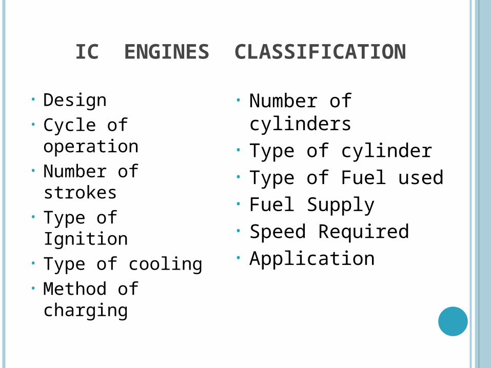
OPPOSITE CYLINDER :-

RADIAL ENGINE :-

Different Cylinder Arrangements in Multi-Cylinder Engines

BASIC ENGINE COMPONENTS
• Cylinder• Piston• Cylinder Head• Connecting Rod• Crankshaft• Piston Rings• Gudgeon Pin• Inlet& exhaust Valve• Spark Plug• Crankcase• Camshaft• Cam


NOMENCLATURE
Cylinder Bore (d) Piston Area (A) Stroke (L) Dead Centers
T.D.C and B.D.C Displacement or Swept Volume (Vs) Clearance Volume (Vc) Compression Ratio (r)


WORKING PRINCIPLES OF IC ENGINES FOUR STROKE ENGINES :
Four Stroke Spark Ignition (SI) Engine
Four Stroke Compression Ignition (CI) Engine TWO STROKE ENGINES:
Two Stroke SI Engines
Two Stroke CI Engines
SPARK IGNITION (SI) ENGINES Spark Is Generated Through An External Source
COMPRESSION IGNITION (CI) ENGINES Air is heated to a sufficiently high temperature because of high
compression ratio. the fuel gets self-ignited on injection as finely atomized spray.

FOUR STROKE SPARK IGNITION (SI) ENGINE
In four stroke engine the cycle of operation is completed in 4 strokes of piston or 2 revolutions of crankshaft.
During four strokes five events to be completed
1)Suction 2)Compression 3)Combustion 4)Expansion 5)Exhaust
Each stroke consists of 180° of crank shaft rotation. Hence four stroke cycle is completed through 720° of crank shaft rotation.
Ideal four stroke engine consists of following 4 strokes.
1. Suction or Intake stroke
2. Compression stroke
3. Expansion or power stroke
4. Exhaust stroke

The SI engines (petrol and gas engines) are used in passenger Cars, Motor Cycles, Air crafts, Agricultural equipments…etc…

As piston moves for TDC to BDC, the inlet valve gets opened while exhaust valve remains closed and fresh air-fuel mixture enters the cylinder.
As piston moves for BDC to TDC, both inlet and exhaust valves remain closed and air-fuel mixture inside cylinder gets compressed.
Highly compressed air-fuel mixture is available inside the cylinder and the spark plug is activated and it releases spark for igniting air-fuel mixture.
Sudden increase in pressure and temperature, the combustion products try to expand and piston moves from TDC to BDC.
During this travel the inlet and exhaust valves remain closed. This is the stroke accompanied by positive work available at shaft. While piston is at BDC the exhaust valve gets opened and combustion products
are exhausted out while piston travels from BDC to TDC. Out of suction, compression, expansion and exhaust strokes only expansion
stroke is accompanied by the production of positive work, Rest three strokes are work absorbing strokes. Work requirement for the three strokes is met from the work available during
expansion stroke. Cycle gets completed in two revolutions of crankshaft.


4 STROKE ENGINE

WORKING PRINCIPLE OF 4 STROKE SI ENGINE
Process in Otto Cycle
1. Isentropic Compression
2. Constant Volume Heat Addition
3. Isentropic Expansion
4. Constant Volume Heat Rejection
Process in SI Engine
1. Suction/ Intake Stroke
2. Compression Stroke or Isentropic Compression
3. Combustion at Constant Volume
4. Power Stroke or Isentropic Expansion
5. Exhaust Stroke

• Process in Otto Cycle
• Suction Or Intake Stroke (0 1) • Compression Stroke ( 1 2)
+ Burning (2 3)• Expansion Or Power Stroke (3 4) • Exhaust Stroke (4 5).
1. Isentropic Compression2. Constant Volume Heat Addition3. Isentropic Expansion4. Constant Volume Heat Rejection
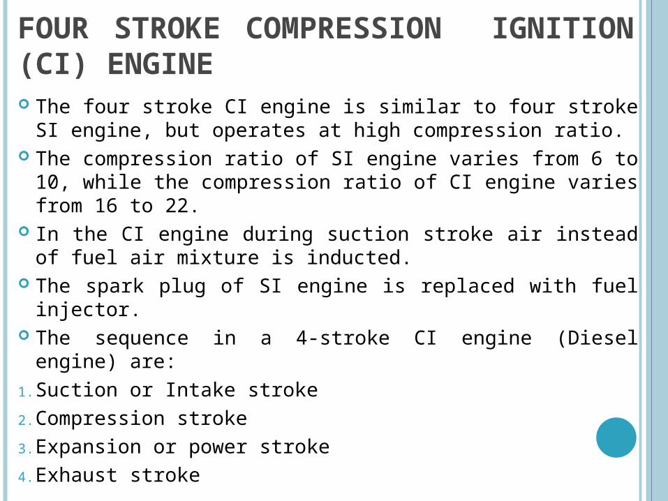
FOUR STROKE COMPRESSION IGNITION (CI) ENGINE The four stroke CI engine is similar to four stroke SI engine, but
operates at high compression ratio. The compression ratio of SI engine varies from 6 to 10, while the
compression ratio of CI engine varies from 16 to 22. In the CI engine during suction stroke air instead of fuel air
mixture is inducted. The spark plug of SI engine is replaced with fuel injector. The sequence in a 4-stroke CI engine (Diesel engine) are:
1. Suction or Intake stroke
2. Compression stroke
3. Expansion or power stroke
4. Exhaust stroke


Piston travels from TDC to BDC and air is sucked into the cylinder. Here inlet valve is open and exhaust valve is closed.
Piston travels from BDC to TDC, while air is compressed with inlet and exhaust valves closed.
Fuel injector injects fuel into compressed air for certain duration. Ignition of fuel also takes place simultaneously as air temperature is much higher than self-ignition temperature of fuel.
Burning of fuel results in release of chemical energy, increasing the pressure, which forces piston to travel from TDC to BDC.
This process is expansion process and piston comes down to BDC with both inlet and exhaust valves closed.
Piston travels up to TDC with exit valve open. During this piston travel burnt gases are expelled out of cylinder. This stroke is Exhaust stroke.
General arrangement in CI engine is similar to that of SI engine with spark plug replaced by fuel injector.

WORKING PRINCIPLE OF 4 STROKE CI ENGINE
Process in Diesel Cycle
1. Isentropic Compression
2. Constant Pressure Heat Addition
3. Isentropic Expansion
4. Constant Volume Heat Rejection
Process in CI Engine
1. Suction/ Intake Stroke
2. Compression Stroke or Isentropic Compression
3. Combustion at Constant Pressure
4. Power Stroke or Isentropic Expansion
5. Exhaust Stroke

• Process in Diesel Cycle• Process in CI Engine
1. Isentropic Compression2. Constant Pressure Heat Addition3. Isentropic Expansion4. Constant Volume Heat Rejection

i) Suction Stroke Air Alone Inducted (0 1)ii) Compression Stroke Air Compressed Into Clearance Volume (1 2)iii) Expansion Stroke Fuel Injection Maintaining Constant Pressure During
Combustion (2 3) + Expansion (3 4)iv) Exhaust Stroke Exhaust Gases Pushed Out (4 5) .

TWO STROKE SI ENGINE
• Douglas Clarke Invented The 2 Stroke Engine In 1878
• In this 2 stroke SI engine the cycle Is completed In one revolution of the Crank Shaft or in two stroke of the piston.
• The main difference between 2-stroke and 4-stroke engine is in the method of filling the fresh charge and removing burnt gases from the cylinder.
• In the 4 stroke engine these operations are performed by the piston during the suction and exhaust strokes respectively.
• In a 2 stroke, the filling process is accomplished by the charge compressed in the crank case. The induction of the compressed charge moves out the product of combustion through exhaust ports. Therefore, no piston strokes are required for these two operations.
• Two strokes are sufficient to complete the cycle, one for compressing the fresh charge and the other for expansion or power stroke.

Construction of 2 Stroke SI Engine

a. Compression/ Ignition b. Expansion and c. Exhaust
Working of a Two-stroke Gasoline Engine

FOUR EVENTS OF 2-S ENGINE

2 STROKE ENGINE

When piston moves from BDC to TDC then the suction port gets uncovered and fresh mixture enters and goes into crank case.
Piston moving from TDC to BDC and during covered position of suction port the mixture gets transferred to the top of piston through transfer port.
During piston travelling from BDC to TDC, the air fuel mixture on top of piston gets compressed and subsequently gets ignited by spark from spark plug.
Release of excessive energy which forces piston to move from TDC to BDC and simultaneously as piston uncovers exhaust port the burnt gases go out through exhaust port.
Suction and compression, both processes get completed during travel of piston from BDC to TDC
Expansion and exhaust processes occur during travel of piston from TDC to BDC along with transfer of fresh fuel air mixture from crankcase to top of piston.
Here all four processes occur during two strokes and one revolution of crank shaft.

IDEAL INDICATOR DIAGRAM OF A TWO STROKE SI ENGINE

TWO STROKE CI (OR) DIESEL ENGINE
• More Advantageous Than Two Stroke SI Engine.
• No Loss Of Fuel With Exhaust Gases As The Intake Charge Is Only Air.
• Hence Many Of The High Output Diesel Engines Work On This Cycle.
• A General Disadvantage Common To Both Two Stroke Gasoline And Diesel Engines Is Greater Cooling And Lubricating Oil Requirements Due To One Power Stroke Per Crank Shaft Rotation And Higher Temperatures.
• Results In Higher Consumption Of Lubricating Oil.

TWO STROKE DIESEL ENGINE

During piston travel from BDC to TDC air enters crankcase. When piston reaches TDC and reverses its motion to BDC, air in
crankcase gets partly compressed and is transferred from crankcase to top of piston through transfer port.
Piston motion from BDC to TDC, the compression of air occurs by the top side of piston while on the bottom side of piston air again enters into crankcase
Upon piston reaching TDC fuel is injected into compressed air which is at high temperature and pressure.
The energy released causes piston to go back from TDC to BDC, i.e. the expansion process.
As piston reaches BDC it simultaneously forces air in crank case to get transferred to cylinder space and forces burnt gases out of cylinder i.e. exhaust process.

The top of the piston has usually a projection to deflect the
fresh charge towards the top of the cylinder before flowing
through the exhaust ports.
This has the dual purpose of
A.Scavenging the upper part of the cylinder of the
combustion products and
B. Preventing the fresh charge from flowing directly
towards the exhaust ports. Scavenging is the process of pushing exhausted gas-charge
out of the cylinder and drawing in a fresh draught of air or fuel/air mixture

Sl.No DESCRIPTION SI ENGINE CI ENGINE
1 Thermodynamic cycle.
Otto cycle. Diesel or dual cycle.
2 Fuel Petrol or gas (costly fuel).
Diesel oil (cheaper fuel).
3 Fuel supply Requires carburetor. Requires Fuel injector.
4 Compression ratio 6 to 10 (average 7-8). 12 to 22 (average 16-17).
5 Combustion or Ignition of charge.
Spark ignition Compression ignition
6 Thermal efficiency
Lower thermal efficiency due to low compression ratio 25%.
High thermal efficiency due to high compression Ratio 40%.
7 Weight Lighter due to low compression ratio and low peak pressure.
Heavier due to high compression ratio and high peak pressure.
COMPARISON OF SI AND CI ENGINES

Sl.No DESCRIPTION SI ENGINE CI ENGINE
8 Speed, operation High speed (2000-6000 rpm)
Low speed (400rpm),
Medium speed (400-1200),
High speed (1200-3500).
9 Noise and vibration
Less More
10 Pollution Less More
11 Cost Cost is low, maintenance is costly due to high cost of fuels.
Initial cost is high.
12 Applications Develops less power and generally used for light duty vehicles (mopeds, cars, aircrafts..etc)
Heavy duty vehicles. Tractors, trucks, locomotives, buses..etc.

ADVANTAGES OF SI ENGINES OVER CI ENGINES
• Initial cost is less• For a given output it is lighter in weight and occupies less
space• Due to low compression it is easy to start• Flotation of speed is minimum and thus requires light
flywheel
Limitations:• Requires costly fuels and maintenance cost is high• Chances of pre ignition of charge are more• Less dependable• Suitable only for light duty vehicles

COMPARISION OF 2-STROKE AND 4-STROKE CYCLE ENGINE
SL.NO 2-STROKE ENGINE 4-STROKE ENGINE
1 All events are completed in 2-strokes of the piston or 1 revolution of crankshaft i.e., there is one power stroke for every revolution of crank shaft.
All events are completed in 4-strokes of the piston or 2 revolution of crankshaft i.e., there is one power stroke for every 2 revolution of crank shaft.
2 Doesn’t have valves and only ports are provided. There ports are closed by piston.
Contains valves and the valves are actuated by cam mechanism.
3 The charge first enters the crankcase, and therefore crank is made gas tight.
The charge is directly admitted into the engine cylinder.
4 Torque is more uniform, requires lighter flywheel.
Torque is not uniform, requires heavier flywheel.
5 Volumetric efficiency is low due to lesser time for suction.
Volumetric efficiency is more due to more time for suction.
6 Thermal efficiency is low. Thermal efficiency is high.

SL.NO 2-STROKE ENGINE 4-STROKE ENGINE
7 Specific fuel consumption is more due to fuel loss through exhaust.
Specific fuel consumption is less.
8 Elimination of suction & exhaust strokes minimizes the frictional loses.
More frictional loses.
9 Consumes more lubricating oil. Consumes less lubricating oil.
10 More noisy in operation. Less noisy.
11 Initial cost is less. Initial cost is more.
12 Higher rate of wear and tear. Lower rate of wear and tear.
13 Generally employed in light duty vehicles such as mopeds, scooters, motor cycles, etc..
Employed in heavy duty vehicles such as cars, buses, trucks, tractors, power generation, industrial engines, aero planes etc..

COOLING SYSTEMS Reasons for providing cooling system1. The even expansion of piston in cylinder may result
in seizure of piston.2. High temperatures reduced strength of piston and
cylinder liner.3. Overheated cylinder may lead to Pre ignition of the
charge, in case of SI engine.4. Physical and chemical changes may occur in
lubricating oil which may cause stocking of the piston rings and excessive wear of cylinder. of lubricant.
There are mainly two methods of cooling IC engine.1) Air cooling or Direct cooling.2) Liquid cooling or Indirect cooling.

AIR COOLING
Heat is carried away by the air flowing over and around the engine cylinder
Used in two wheelers, Fins are cut on the cylinder
ADVANTAGES: Simple cooling system No danger of coolant leakage No trouble of freezing of coolant Installation is easier No external components like tank and radiator
DISADVANTAGES: Their movement is noisy Non uniform cooling Output of engine is less Maintenance is not easy Applicable for smaller compression ratio

LIQUID COOLING
Cylinder head and wall are provided with jackets through which the cooling liquid is circulated
Heat is transferred by means of conduction and convection
Heated liquid rejects heat to air by air cooled radiator system.

ADVANTAGES:
Fuel consumption is low Cooling system can be located where ever required Higher heat transfer rate is achieved Compact design of engine
DISADVANTAGES: Continuous supply of water is required In case of failure serious damage may be caused to the engine Cost of system is high Maintenance of various parts of system

LUBRICATION SYSTEM Lubrication is the admittance of oil between two surfaces having
relative motion
Purpose of lubrication
1. Reduce friction and wear
2. Cooling of surface (heat due to friction)
3. Seal space between adjoining surfaces
4. Clean the surface by carrying away the carbon and metal particles caused by wear

PROPERTIES:•Fire point
Lowest temp at which oil burns continuously
•Cloud point
Temp at which change of state takes places
•Pour temperature
Temp at which the oil will pour. Ability to move at low temp
•Oiliness
Property which enables oil to spread over

• Corrosion
Should not corrode the working parts
• Physical and chemical stability
Physically and chemically stable between operating temperatures
• Adhesiveness
Oil particles stick to the metal surface
• Specific gravity
It is the measure of density of oil

TYPES OF LUBRICATION SYSTEM
A. Wet sump lubrication
1.Splash
2.Semi pressure system or Pressure Fed or Force Feed.
3.Full pressure system or Combination Pressure Fed and Splash.
B. Dry sump lubrication
C. Mist lubrication
1.Gasoline Oil Premix


ENGINE PERFORMANCE PARAMETERS
Sl. No.Sl. No. ParameterParameter NotationNotation
i.i. Indicated Thermal EfficiencyIndicated Thermal Efficiency ηηithith
iiii Brake Thermal EfficiencyBrake Thermal Efficiency ηηbthbth
iiiiii Mechanical EfficiencyMechanical Efficiency ηηmm
iviv Volumetric EfficiencyVolumetric Efficiency ηηvv
vv Relative Efficiency/ Efficiency RatioRelative Efficiency/ Efficiency Ratio ηηrelrel
vivi Mean Effective PressureMean Effective Pressure ppmm
viivii Specific Power OutputSpecific Power Output PPss
viiiviii Specific Fuel ConsumptionSpecific Fuel Consumption sfcsfc
IxIx Fuel-Air or Air-Fuel RatioFuel-Air or Air-Fuel Ratio F/A or A/FF/A or A/F
xx Calorific value of the FuelCalorific value of the Fuel CV (HCV/ LCV)CV (HCV/ LCV)

ENGINE PERFORMANCE PARAMETERS The engine performance s indicated by the term η. Calorific value: It is the thermal energy released per unit quantity
of the fuel when the fuel is burned completely and the products of combustion are cooled back to the initial temperature at the combustion mixture.
Indicated power (I.P): The total power developed by combustion of the fuel in the combustion chamber is called indicated power.
Break power (B.P): The power developed by an engine at the out put shaft is called break power. The difference between I.P and B.P is called frictional power (F.P).
F.P=I.P-B.P Indicated Thermal Efficiency ηith : It is the ratio of energy in the
indicated power, to the input fuel energy in appropriate units.

ENGINE PERFORMANCE PARAMETERS Break thermal efficiency ηηbthbth : it is the ratio of energy in the brake
power, BP to the input fuel energy in appropriate units. Mechanical efficiency ηηm m : it is defined as the ratio of brake power
(delivered power) to the indicated power (power provided to the piston) Or
It can also be defined as the ratio of the brake thermal efficiency to the indicated thermal efficiency.
Volumetric efficiency ηηvv : it is the ratio of the volume of air : it is the ratio of the volume of air
actually inducted at ambient conditions to the swept volume of the actually inducted at ambient conditions to the swept volume of the engine.engine.
Relative efficiency or Efficiency ratio:Relative efficiency or Efficiency ratio: it is the ratio between it is the ratio between actual thermal efficiency to the ideal efficiency (air standard actual thermal efficiency to the ideal efficiency (air standard efficiency) of the cycle employed.efficiency) of the cycle employed.

ENGINE PERFORMANCE PARAMETERS
Mean effective pressure: it is the average pressure inside the cylinders of an I.C engine based on the measured power output.
Specific power out put: it is defined as the break output per unit of piston displacement.
Fuel-air ratio: it is the ratio of the mass of the fuel to the mass of the air in the air fuel mixture.
Specific fuel consumption: it is the mass of the fuel consumed per KW developed per hour and is a criterion of economical power production.