Embed Size (px)
Citation preview
Page 1/12
Metamaterial Microwave Absorber (MMA)) forElectromagnetic Interference (EMI)) Shielding in X-bandRakesh Mishra
Defence Institute of Advanced Technology Department of Applied PhysicsRavi Gupta
Defence Institute of Advanced TechnologySuwarna Datar ( [email protected] )
Defence Institute of Advanced Technology Department of Applied Physics https://orcid.org/0000-0002-9513-0064
Research Article
Keywords: Metamaterial, Rotational symmetry, Microwave Absorber, EMI shielding
Posted Date: March 24th, 2021
DOI: https://doi.org/10.21203/rs.3.rs-335762/v1
License: This work is licensed under a Creative Commons Attribution 4.0 International License. Read Full License
Page 2/12
AbstractThe present paper is aimed at investigating application of planar Metamaterial (MM) structures foreffective EMI Shielding and Stealth applications in X-Band. Various MM structures using FR4 substrateand Copper conductors were conceived and designed followed by simulations carried out using CSTMWS Suite software. As a �rst step, the de- signs were aimed at achieving extremely high absorption fornormal incidence, polarisation independence and maintaining high absorption in wide angle performancewhile keeping the requirement of light weight, �exibility and environmental ruggedness in mind fordeployability on platforms to achieve effective stealth against Radars and for other EMI shieldingapplications. Circularly symmetric, single layer Metamaterial Microwave Absorber (MMA) design over thinFR4 substrate in spokes and wheel structural arrangement provided these desired features. The thin FR4substrate of 0.6 mm provides the light weight and �exibility while absorbing the EM waves. Rotationalsymmetry of the spoke and cut-wheel design gives it polarisation independence and 4 ring planar arrayconcept with rings scaled to different sizes in the same plane in the unit cell provided the increase inbandwidth. Reduction in received signal level of the echo is depicted by the S-Parameter at the input port.Getting values of this S-Parameter less than -60dB at resonant frequency for MMAs is highly encouragingand is not reported much in literature. Enhancement of nearly 3-8 times in operating bandwidth wasachieved by changing size of rings in each quadrant in the co-planar array having four resonant rings ineach unit cell.
Full TextThis preprint is available for download as a PDF.
Figures
Page 3/12
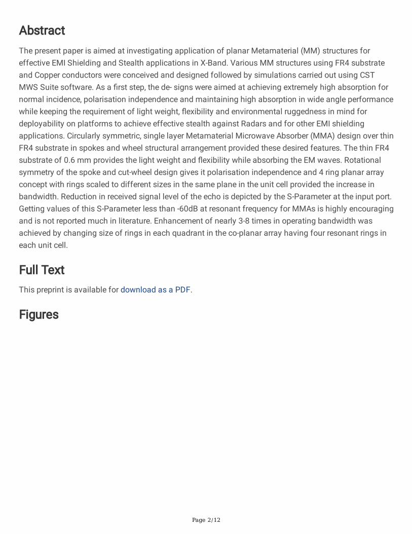
Figure 1
Orthographic front view of the proposed MMA with spoke and wheel structure
Page 4/12
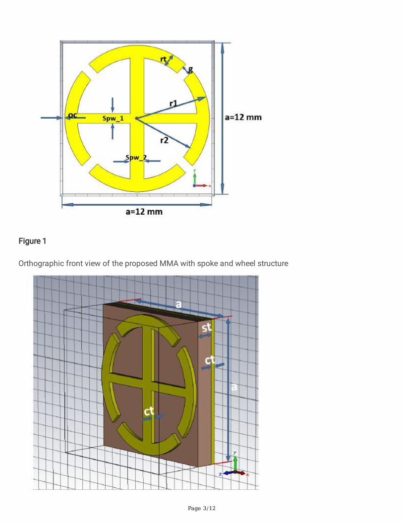
Figure 2
Perspective schematic view of proposed MMA
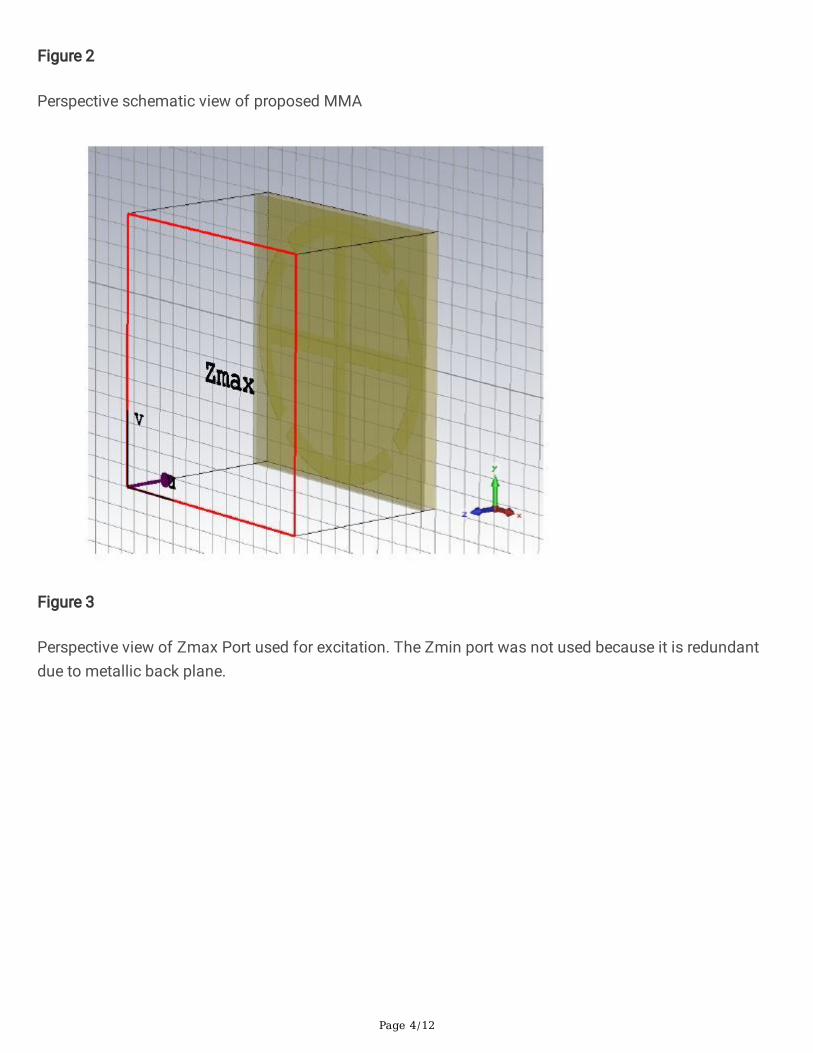
Figure 3
Perspective view of Zmax Port used for excitation. The Zmin port was not used because it is redundantdue to metallic back plane.
Page 5/12
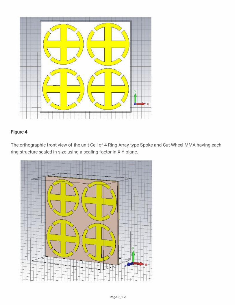
Figure 4
The orthographic front view of the unit Cell of 4-Ring Array type Spoke and Cut-Wheel MMA having eachring structure scaled in size using a scaling factor in X-Y plane.
Page 6/12
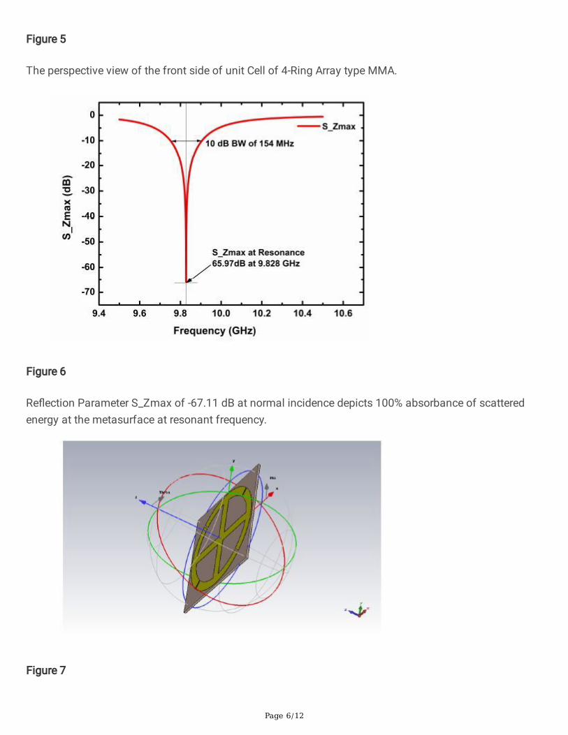
Figure 5
The perspective view of the front side of unit Cell of 4-Ring Array type MMA.
Figure 6
Re�ection Parameter S_Zmax of -67.11 dB at normal incidence depicts 100% absorbance of scatteredenergy at the metasurface at resonant frequency.
Figure 7
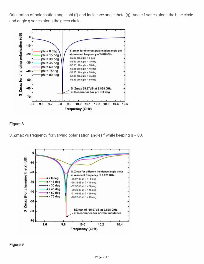
Page 7/12
Orientation of polarisation angle phi (f) and incidence angle theta (q). Angle f varies along the blue circleand angle q varies along the green circle.
Figure 8
S_Zmax vs frequency for varying polarisation angles f while keeping q = 00.
Figure 9
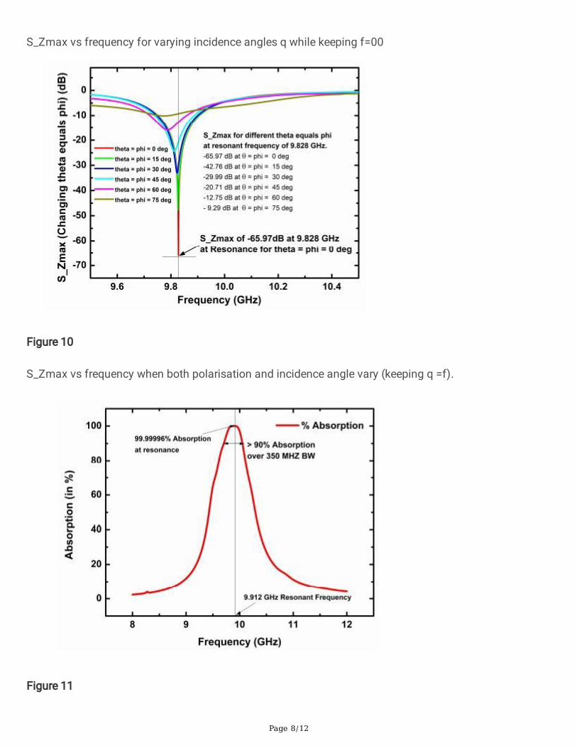
Page 8/12
S_Zmax vs frequency for varying incidence angles q while keeping f=00
Figure 10
S_Zmax vs frequency when both polarisation and incidence angle vary (keeping q =f).
Figure 11
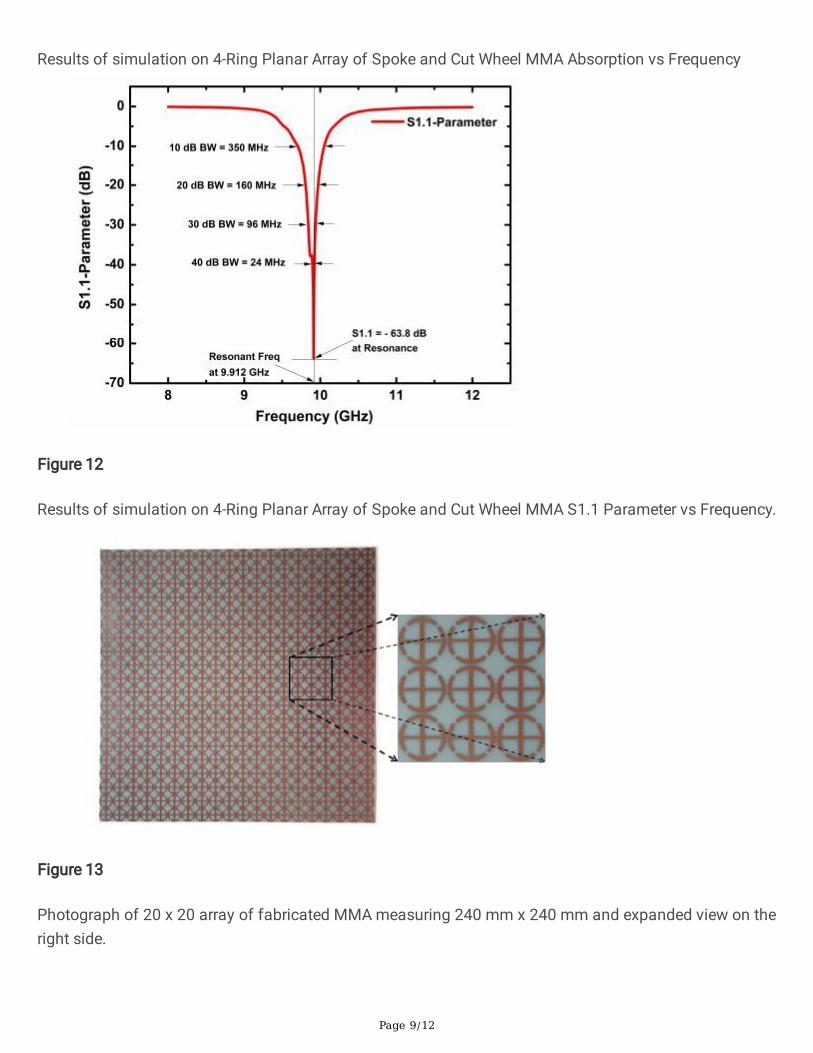
Page 9/12
Results of simulation on 4-Ring Planar Array of Spoke and Cut Wheel MMA Absorption vs Frequency
Figure 12
Results of simulation on 4-Ring Planar Array of Spoke and Cut Wheel MMA S1.1 Parameter vs Frequency.
Figure 13
Photograph of 20 x 20 array of fabricated MMA measuring 240 mm x 240 mm and expanded view on theright side.
Page 10/12
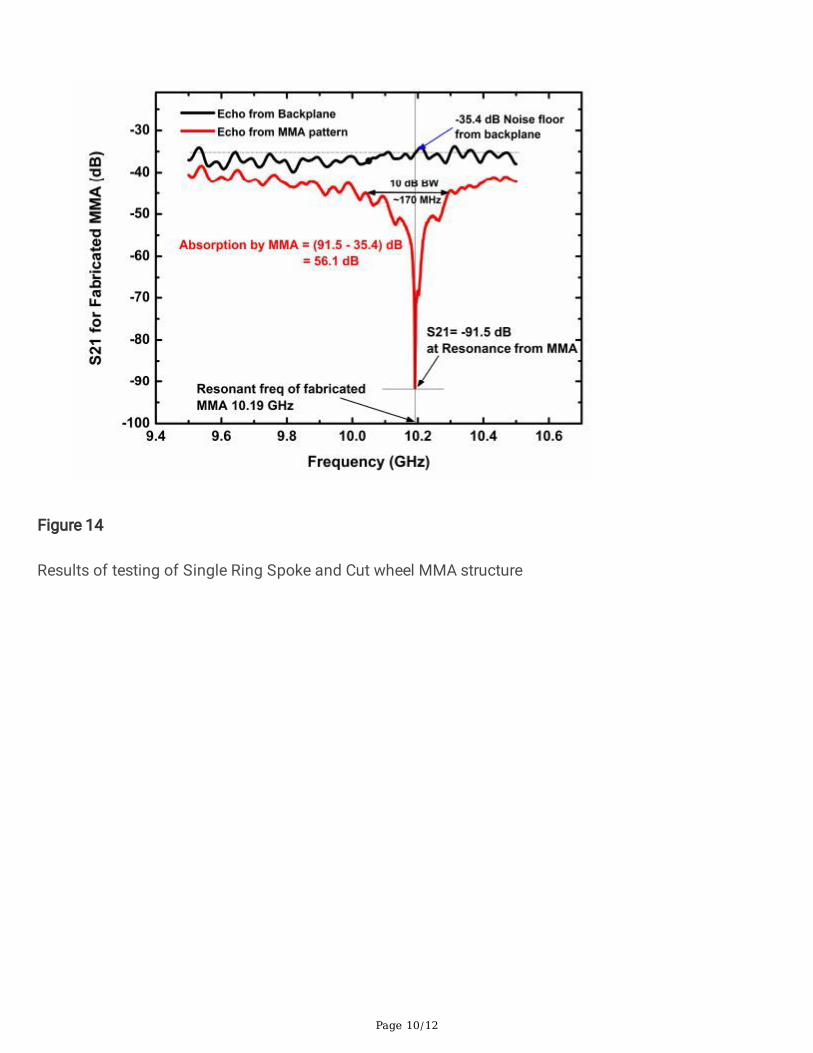
Figure 14
Results of testing of Single Ring Spoke and Cut wheel MMA structure
Page 11/12
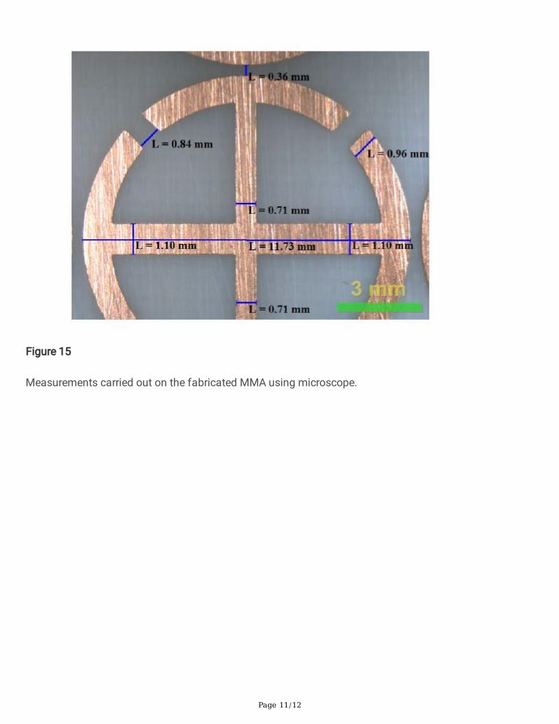
Figure 15
Measurements carried out on the fabricated MMA using microscope.
Page 12/12
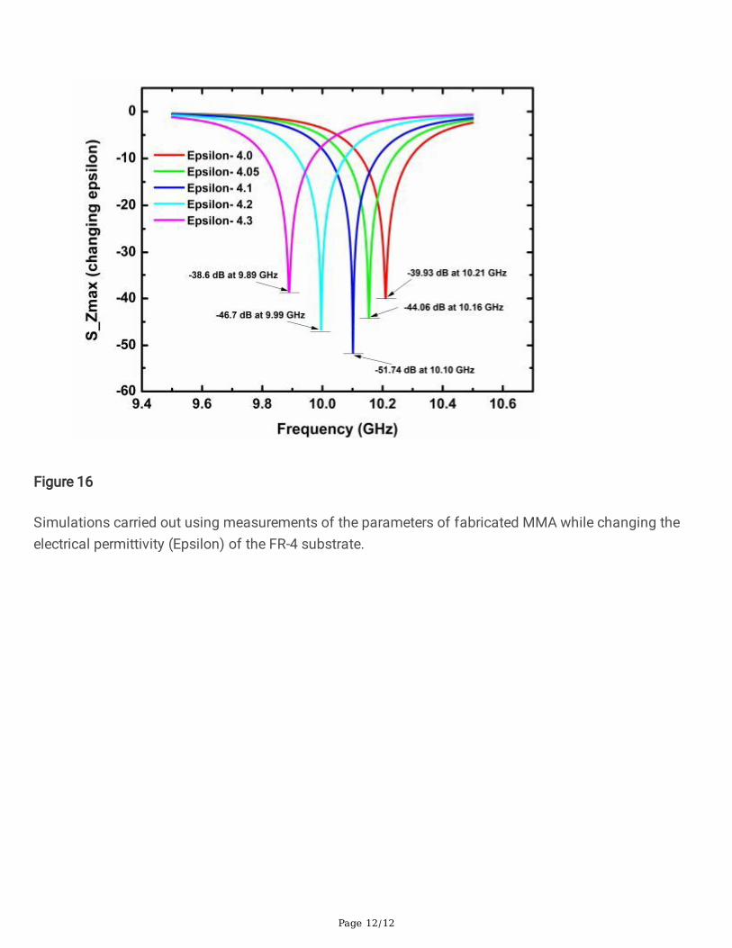
Figure 16
Simulations carried out using measurements of the parameters of fabricated MMA while changing theelectrical permittivity (Epsilon) of the FR-4 substrate.