Embed Size (px)
Citation preview
The Shipowners’ Protection LimitedSt Clare House30-33 MinoriesLondonEC3N 1BP
Tel: +44 (0)20 7488 0911Fax: +44 (0)20 7480 5806Email: [email protected]
www.shipownersclub.com
Published November 2007
Basic Stability for Small Ve s s e l s
Index
2 Introduction
4 Lack of Understanding of Stability Criteria
6 Stability Requirements
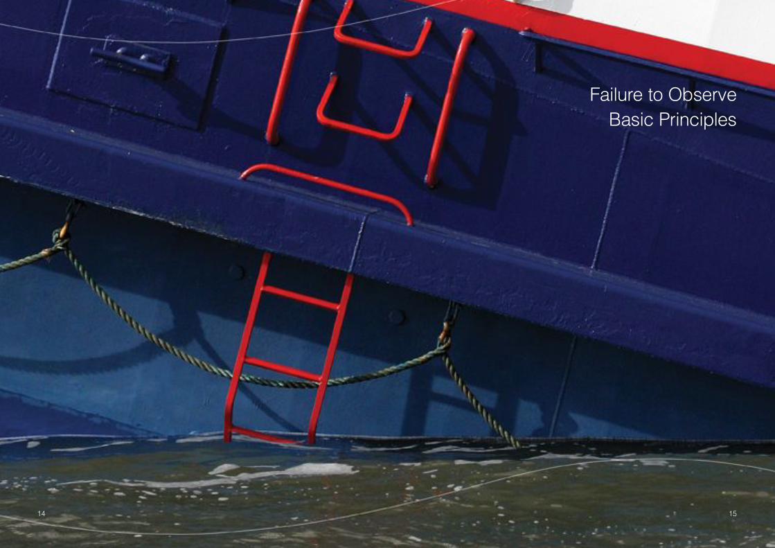
14 Failure to Observe Basic Principles
16 Pre Load Requirements
16 Free Surface Effect
17 Estimating Centre of Gravity
17 Container Heights
17 Container Weights
18 Draft
19 Cranes and Derricks
20 Overloading
20 Reductions in Freeboard
21 Failure to Confirm the Vessel’s Condition
22 Errors in Calculations
24 Computers
27 Conclusion
28 Appendices
30 Appendix 1: Proforma Calculation Sheet (VCG)
31 Appendix 2: Examples of Calculating Stability Conditions
42 Case Studies
1
Notwithstanding the type of dry cargo vessel or barge, the predominant cause of claims we
see is a lack of adequate transverse stability on vessels carrying containers. Although the
majority of incidents occurred either on specific container vessels or cargo vessels carrying
containers, stability issues are equally important on all types of vessels. Fortuitously most
incidents have not resulted in a total loss. This is mainly because as the vessels listed over,
the cargo has fallen overboard and positive stability was regained, allowing the vessel to
return to near upright. In other cases, the vessels developed an angle of loll and upon arrival
in port, with the assistance of the authorities, the upper tiers of containers were removed and
positive stability was regained by lowering the overall KG. If a vessel were to experience the
serious effects of insufficient stability whilst in a heavy sea where dynamic stability is crucial,
the results may not be so fortunate with loss of the vessel and life a real possibility.
The Club has also dealt with claims arising from flat barges carrying scrap metal. In each
case the vessel capsized but did not sink, but in all probability the cause was inadequate
stability compounded by the shifting of cargo.
Causes
We have found it rare that an unsatisfactory situation regarding the vessel’s stability develops
though a single cause. In our experience it usually arises through a collection of one or more
of the following factors:-
! Lack of understanding of the stability criteria
! A failure to observe basic principles
! Arithmetical errors in calculations
I n t ro d u c t i o nMany different types of vessels are entered in the Club, each possessing their own unique
stability requirements.
Generally speaking tankers, bulk carriers and passenger vessels retain more than sufficient
stability to ensure compliance with the regulations when fully loaded. Dry cargo ships,
container carriers and barges are subject to large reductions in stability when loaded
therefore care must be taken to ensure the condition of the vessel complies with the
regulations which lay down the minimum stability requirements. If these are not complied with,
then the safety of the vessel, her crew and cargo will be compromised.
Over the years the Club has dealt with a number of claims involving general cargo vessels
and container ships that have been caused by the vessel having inadequate stability and
being allowed to undertake a voyage in that condition. There have also been a large number
of similar incidents involving flat top barges loaded with break bulk, containers, scrap metal or
combinations of all three. In most cases the lack of sufficient stability has not been made
apparent until an external force has acted on the vessel caused by heavy sea conditions, a
sharp alteration of course or the pushing of an assisting tug.
Prompted by these claims, the Club has published this booklet on basic stability aimed
primarily at Members and crews of dry cargo vessels. The purpose of the booklet is to explain
the fundamentals of stability and explanations as to how it can be determined which is not
always readily understood by crews and personnel responsible for loading vessels. All to
often the GM is taken to be the measure of a vessel’s stability and this is an incorrect
assumption.
Appendix 2 contains a number of stability calculation examples and the Case Studies
describe the circumstances leading to actual related claims dealt with by the Club.
2 3
Introduction
Lack of Understanding of Stability Criteria
4 5
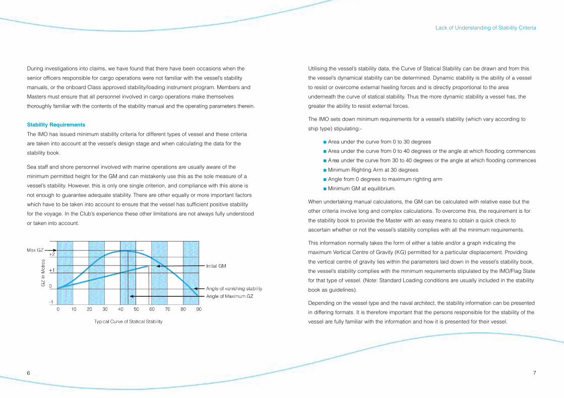
Utilising the vessel’s stability data, the Curve of Statical Stability can be drawn and from this
the vessel’s dynamical stability can be determined. Dynamic stability is the ability of a vessel
to resist or overcome external heeling forces and is directly proportional to the area
underneath the curve of statical stability. Thus the more dynamic stability a vessel has, the
greater the ability to resist external forces.
The IMO sets down minimum requirements for a vessel’s stability (which vary according to
ship type) stipulating:-
! Area under the curve from 0 to 30 degrees
! Area under the curve from 0 to 40 degrees or the angle at which flooding commences
! A rea under the curve from 30 to 40 degrees or the angle at which flooding commences
! Minimum Righting Arm at 30 degrees
! Angle from 0 degrees to maximum righting arm
! Minimum GM at equilibrium.
When undertaking manual calculations, the GM can be calculated with relative ease but the
other criteria involve long and complex calculations. To overcome this, the requirement is for
the stability book to provide the Master with an easy means to obtain a quick check to
ascertain whether or not the vessel’s stability complies with all the minimum requirements.
This information normally takes the form of either a table and/or a graph indicating the
maximum Vertical Centre of Gravity (KG) permitted for a particular displacement. Providing
the vertical centre of gravity lies within the parameters laid down in the vessel’s stability book,
the vessel’s stability complies with the minimum requirements stipulated by the IMO/Flag State
for that type of vessel. (Note: Standard Loading conditions are usually included in the stability
book as guidelines).
Depending on the vessel type and the naval architect, the stability information can be pre s e n t e d
in differing formats. It is therefore important that the persons responsible for the stability of the
vessel are fully familiar with the information and how it is presented for their vessel.
During investigations into claims, we have found that there have been occasions when the
senior officers responsible for cargo operations were not familiar with the vessel’s stability
manuals, or the onboard Class approved stability/loading instrument program. Members and
Masters must ensure that all personnel involved in cargo operations make themselves
t h o roughly familiar with the contents of the stability manual and the operating parameters there i n .
Stability Requirements
The IMO has issued minimum stability criteria for different types of vessel and these criteria
are taken into account at the vessel’s design stage and when calculating the data for the
stability book.
Sea staff and shore personnel involved with marine operations are usually aware of the
minimum permitted height for the GM and can mistakenly use this as the sole measure of a
vessel’s stability. However, this is only one single criterion, and compliance with this alone is
not enough to guarantee adequate stability. There are other equally or more important factors
which have to be taken into account to ensure that the vessel has sufficient positive stability
for the voyage. In the Club’s experience these other limitations are not always fully understood
or taken into account.
6 7
Lack of Understanding of Stability Criteria
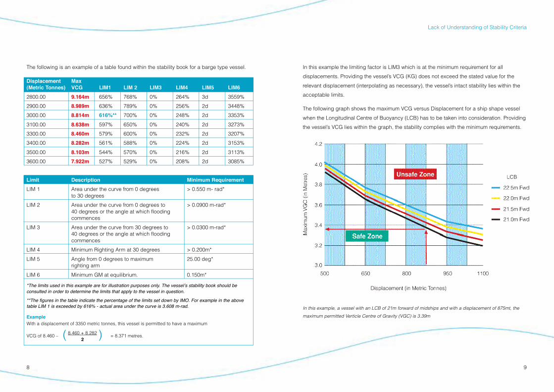
The following is an example of a table found within the stability book for a barge type vessel.
Displacement Max
(Metric Tonnes) VCG LIM1 LIM 2 LIM3 LIM4 LIM5 LIM6
2800.00 9.164m 656% 768% 0% 264% 3d 3559%
2900.00 8.989m 636% 789% 0% 256% 2d 3448%
3000.00 8.814m 616%** 700% 0% 248% 2d 3353%
3100.00 8.638m 597% 650% 0% 240% 2d 3273%
3300.00 8.460m 579% 600% 0% 232% 2d 3207%
3400.00 8.282m 561% 588% 0% 224% 2d 3153%
3500.00 8.103m 544% 570% 0% 216% 2d 3113%
3600.00 7.922m 527% 529% 0% 208% 2d 3085%
Limit Description Minimum Requirement
LIM 1 Area under the curve from 0 degrees > 0.550 m- rad*to 30 degrees
LIM 2 Area under the curve from 0 degrees to > 0.0900 m-rad*40 degrees or the angle at which flooding commences
LIM 3 Area under the curve from 30 degrees to > 0.0300 m-rad*40 degrees or the angle at which flooding commences
LIM 4 Minimum Righting Arm at 30 degrees > 0.200m*
LIM 5 Angle from 0 degrees to maximum 25.00 deg*righting arm
LIM 6 Minimum GM at equilibrium. 0.150m*
*The limits used in this example are for illustration purposes only. The vessel!s stability book should be
consulted in order to determine the limits that apply to the vessel in question.
**The figures in the table indicate the percentage of the limits set down by IMO. For example in the above
table LIM 1 is exceeded by 616% - actual area under the curve is 3.608 m-rad.
Example
With a displacement of 3350 metric tonnes, this vessel is permitted to have a maximum
VCG of 8.460 – ( 8.460 + 8.282 ) = 8.371 metres.2
8 9
Lack of Understanding of Stability Criteria
In this example the limiting factor is LIM3 which is at the minimum requirement for all
displacements. Providing the vessel’s VCG (KG) does not exceed the stated value for the
relevant displacement (interpolating as necessary), the vessel’s intact stability lies within the
acceptable limits.
The following graph shows the maximum VCG versus Displacement for a ship shape vessel
when the Longitudinal Centre of Buoyancy (LCB) has to be taken into consideration. Providing
the vessel’s VCG lies within the graph, the stability complies with the minimum requirements.
In this example, a vessel with an LCB of 21m forward of midships and with a displacement of 875mt, the
maximum permitted Verticle Centre of Gravity (VGC) is 3.39m
10 11
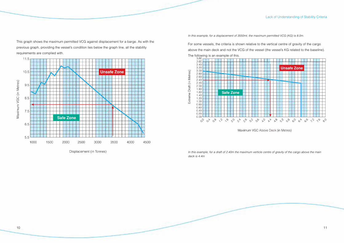
This graph shows the maximum permitted VCG against displacement for a barge. As with the
previous graph, providing the vessel’s condition lies below the graph line, all the stability
requirements are complied with.
Lack of Understanding of Stability Criteria
In this example, for a displacement of 3550mt, the maximum permitted VCG (KG) is 8.0m.
For some vessels, the criteria is shown relative to the vertical centre of gravity of the cargo
above the main deck and not the VCG of the vessel (the vessel’s KG related to the baseline).
The following is an example of this.
In this example, for a draft of 2.40m the maximum verticle centre of gravity of the cargo above the main deck is 4.4m
12 13
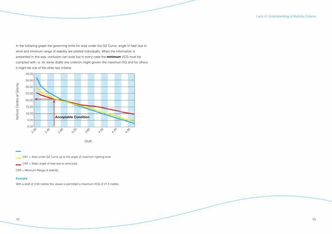
In the following graph the governing limits for area under the GZ Curve, angle of heel due to
wind and minimum range of stability are plotted individually. When the information is
presented in this way, confusion can exist but in every case the minimum VCG must be
complied with i.e. for some drafts one criterion might govern the maximum KG and for others
it might be one of the other two criteria.
CR1 = Area under GZ Curve up to the angle of maximum righting lever
CR2 = Static angle of heel due to wind load
CR3 = Minimum Range of stability
Example
With a draft of 2.60 metres this vessel is permitted a maximum VCG of 21.0 metres.
Lack of Understanding of Stability Criteria
F a i l u re to Observe Basic Principles
14 15
1716
Estimating Centre of Gravity
Masters are reminded of the need for accurate estimation of a cargo’s centre of gravity. Errors
can accumulate if incorrect assumptions are made which can then compromise a vessel’s
stability. Estimations should always err on the side of safety (i.e. it is better to estimate too high
rather than too low). The centre of gravity of a container should always be assumed to be at mid
height unless it is known to be different (some Classification Societies use 0.4 x container
height).
Container Heights
Consideration should be given to ensuring the correct container heights are used when
calculating the VCG. Whilst the actual difference between an 8’ 00”, 8’ 06”, 9’ 00” or 9’ 06” (Hi
Cube) high container is not significant when considered individually, a large number of incorrect
heights can have an adverse effect on the final VCG if not allowed for, particularly on smaller
vessels.
Container Weights
The incorrect declaration of container weights is a problem encountered throughout the
container shipping world and can manifest itself more in the local trades that our Members
operate in rather than the main line trade.
Unfortunately this problem is one that is generally outside the control of Masters and
shipowners. Visually there is no means to assess the weight of a container and the Master has
to take the manifest or bill of lading at face value. this cannot be totally relied on, it places more
emphasis on the need to monitor the vessels actual drafts during loading. If discrepancies arise
they can be investigated further or allowed for by assuming the worst case scenarios.
Another problem with not knowing the weights of containers loaded, is the possibility that
Pre Load Requirements
Persons responsible for loading a vessel or barge, must ensure that they are made aware of
the cargo weights to be loaded and the height of their centres of gravity. This information,
wherever possible should be determined before loading operations are commenced, so that a
safe load sequence can be calculated beforehand and that no nasty surprises are
encountered at the last minute.
Notwithstanding any pressure placed on the vessel by the shore terminal, the
responsibility for loading remains with the Master alone.
Free Surface Effect (FSE)
The free surface effect of any liquids on board has a marked impact on the vessel’s stability
by reducing the effective GM (or conversely by effectively increasing the KG). Some of the
claims the Club has dealt with have highlighted the fact that either no account of FSE had
been taken, or if it had, the data was incorrectly applied.
Ideally, ballast tanks should either be pressed up full or completely empty so there is no free
surface effect to consider. However, when this is not possible, it is best practice to initially
allow the maximum FSE for each and every slack tank in the stability calculations. If the
stability condition is then noted to be critical for any stage of the voyage, the actual free
surface moments can be applied to the calculation in order to obtain an accurate assessment
of the vessel’s condition.
It is essential that the FSE is always calculated and applied correctly and Masters should be
given clear guidance on the Member’s requirement in this regard. It should also be borne in
mind that free water on the decks has the same effect and when the stability condition is
critical it can have a major impact.
Failure to observe basic principles
1918
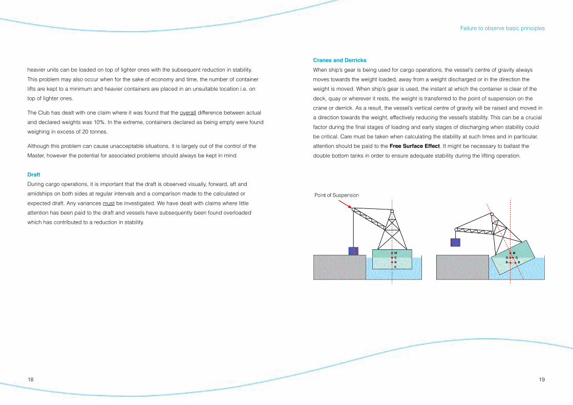
Cranes and Derricks
When ship’s gear is being used for cargo operations, the vessel’s centre of gravity always
moves towards the weight loaded, away from a weight discharged or in the direction the
weight is moved. When ship’s gear is used, the instant at which the container is clear of the
deck, quay or wherever it rests, the weight is transferred to the point of suspension on the
crane or derrick. As a result, the vessel’s vertical centre of gravity will be raised and moved in
a direction towards the weight, effectively reducing the vessel’s stability. This can be a crucial
factor during the final stages of loading and early stages of discharging when stability could
be critical. Care must be taken when calculating the stability at such times and in particular,
attention should be paid to the Free Surface Effect. It might be necessary to ballast the
double bottom tanks in order to ensure adequate stability during the lifting operation.
heavier units can be loaded on top of lighter ones with the subsequent reduction in stability.
This problem may also occur when for the sake of economy and time, the number of container
lifts are kept to a minimum and heavier containers are placed in an unsuitable location i.e. on
top of lighter ones.
The Club has dealt with one claim where it was found that the overall difference between actual
and declared weights was 10%. In the extreme, containers declared as being empty were found
weighing in excess of 20 tonnes.
Although this problem can cause unacceptable situations, it is largely out of the control of the
Master, however the potential for associated problems should always be kept in mind.
Draft
During cargo operations, it is important that the draft is observed visually, forward, aft and
amidships on both sides at regular intervals and a comparison made to the calculated or
expected draft. Any variances must be investigated. We have dealt with claims where little
attention has been paid to the draft and vessels have subsequently been found overloaded
which has contributed to a reduction in stability.
Failure to observe basic principles

Failure to Confirm the Ve s s e l !s Condition
It is imperative that at all stages of a vessel’s cargo operations the vessel maintains a stability
condition that complies fully with the stability criteria for that vessel. This requirement is
equally important for all stages of the voyage as well, and consideration has to be taken for
the consumption of fuel, water and stores and the free surface effects this might introduce. It
might be necessary to ballast the vessel to compensate for these consumables being used. If
this action is necessary, then the free surface effect of water being introduced into the ballast
tanks must be taken into account before any ballasting operations are carried out. It is not
uncommon for ballasting a tank to initially make the situation worse before an improvement in
the stability condition is achieved.
Failure to observe basic principles
20 21
Overloading
Following plan approval and periodic loadline surveys, all vessels are issued with a Loadline
Certificate by the Flag State (or issued by a Classification Society on behalf of the
Administration). This document alone is the overriding authority governing the minimum fre e b o a rd
a vessel is permitted to load to. The Club has known cases whereby information from an
unapproved stability manual was used for loadline purposes and this was found to be incorrect.
A vessel is automatically considered unseaworthy if she puts to sea with a freeboard less than
that permitted. Masters should be made aware of the fact that if a vessel is overloaded the P&I
cover may well be invalidated.
Reductions in Freeboard
The Club is aware of instances whereby the freeboard of a vessel has been reduced (with the
agreement of the local Authorities) because it is trading in coastal or local waters. If a reduction
is being considered then it is imperative that a study of the vessel’s revised stability conditions
is carried out by a Naval Architect to ensure they still comply with the regulations. A reduction in
freeboard to permit a greater cargo carrying capacity for the vessel will result in a loss of
reserve buoyancy and this consequently will reduce the dynamic stability of the vessel and the
ability to resist external forces.
26 2722 23
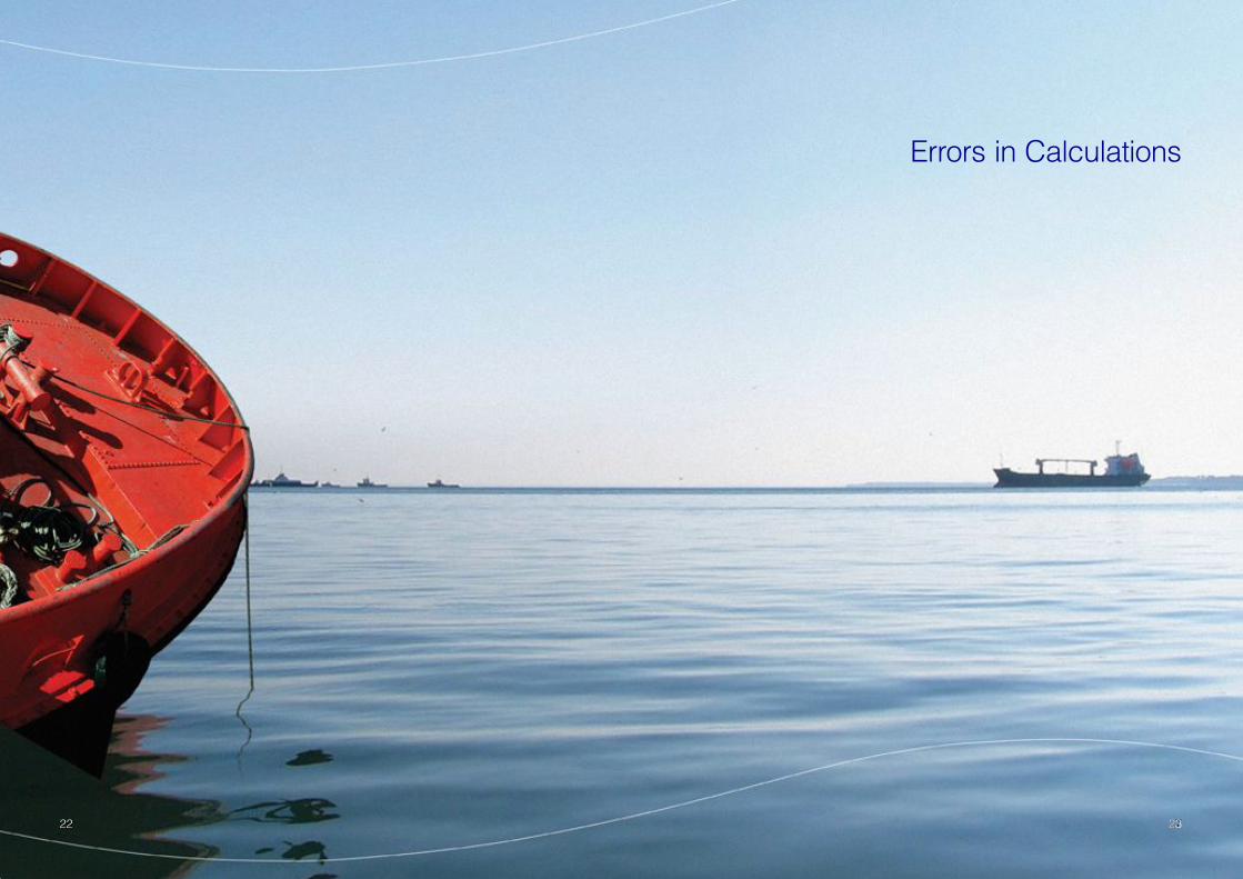
E rrors in Calculations
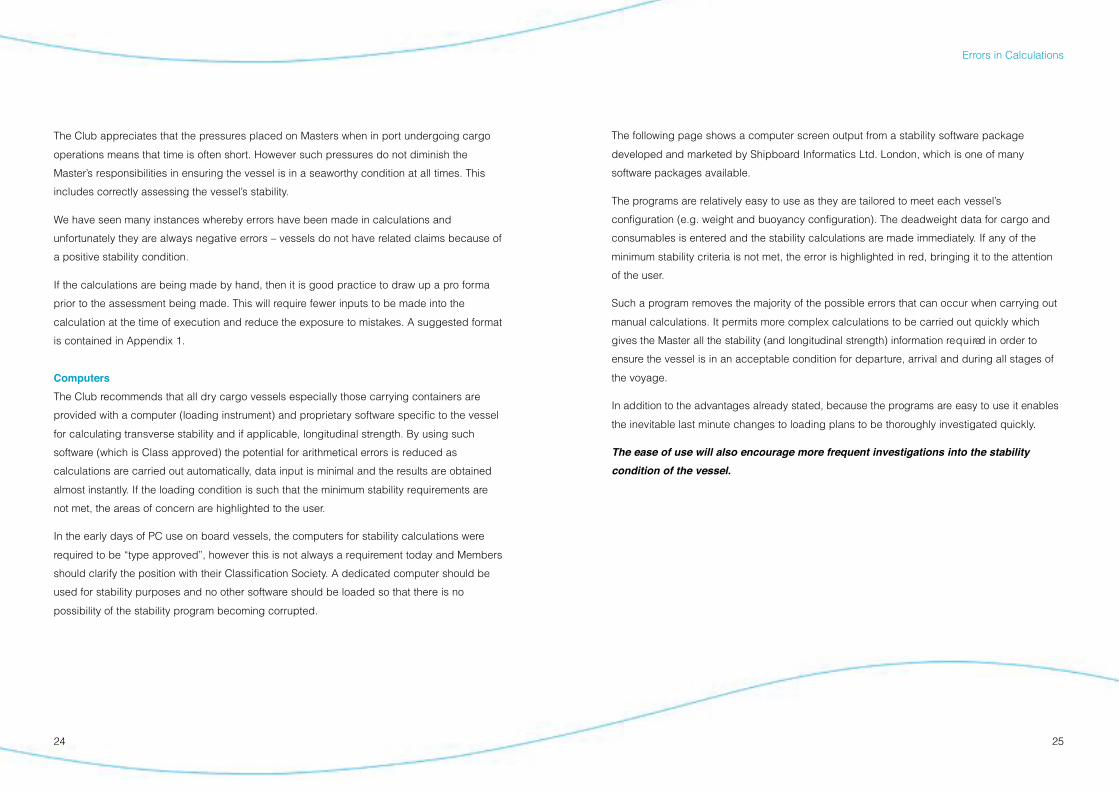
2524
The following page shows a computer screen output from a stability software package
developed and marketed by Shipboard Informatics Ltd. London, which is one of many
software packages available.
The programs are relatively easy to use as they are tailored to meet each vessel’s
configuration (e.g. weight and buoyancy configuration). The deadweight data for cargo and
consumables is entered and the stability calculations are made immediately. If any of the
minimum stability criteria is not met, the error is highlighted in red, bringing it to the attention
of the user.
Such a program removes the majority of the possible errors that can occur when carrying out
manual calculations. It permits more complex calculations to be carried out quickly which
gives the Master all the stability (and longitudinal strength) information re q u i red in order to
e n s u re the vessel is in an acceptable condition for departure, arrival and during all stages of
the voyage.
In addition to the advantages already stated, because the programs are easy to use it enables
the inevitable last minute changes to loading plans to be thoroughly investigated quickly.
The ease of use will also encourage more frequent investigations into the stability
condition of the vessel.
The Club appreciates that the pressures placed on Masters when in port undergoing cargo
operations means that time is often short. However such pressures do not diminish the
Master’s responsibilities in ensuring the vessel is in a seaworthy condition at all times. This
includes correctly assessing the vessel’s stability.
We have seen many instances whereby errors have been made in calculations and
unfortunately they are always negative errors – vessels do not have related claims because of
a positive stability condition.
If the calculations are being made by hand, then it is good practice to draw up a pro forma
prior to the assessment being made. This will require fewer inputs to be made into the
calculation at the time of execution and reduce the exposure to mistakes. A suggested format
is contained in Appendix 1.
Computers
The Club recommends that all dry cargo vessels especially those carrying containers are
provided with a computer (loading instrument) and proprietary software specific to the vessel
for calculating transverse stability and if applicable, longitudinal strength. By using such
software (which is Class approved) the potential for arithmetical errors is reduced as
calculations are carried out automatically, data input is minimal and the results are obtained
almost instantly. If the loading condition is such that the minimum stability requirements are
not met, the areas of concern are highlighted to the user.
In the early days of PC use on board vessels, the computers for stability calculations were
required to be “type approved”, however this is not always a requirement today and Members
should clarify the position with their Classification Society. A dedicated computer should be
used for stability purposes and no other software should be loaded so that there is no
possibility of the stability program becoming corrupted.
Errors in Calculations
Stability Software Screen Display
26 27
C o n c l u s i o nThe Master or person responsible for the loading of the vessel should not depart a berth until
the intact stability of the vessel has been calculated and it is confirmed that the statutory
stability requirements, as included in the stability book approved by Class on behalf of the
respective flag administration are complied with during all stages of the voyage. If it is not
possible to comply, the Master should take whatever action is necessary in order to arrive at a
condition that ensures the vessel is seaworthy throughout the voyage. Such action may
include off loading cargo, ballasting the vessel or both.
It is good practice for Members to have clear written instructions for their Masters to cover
such eventualities as stated above. It is also prudent for these instructions to cover the
requirement for all stability issues to be adhered to and what action to take if they cannot be.
Providing Masters know they have the backing of their operating company, there is less
chance of errors being made and vessels putting to sea in an unseaworthy condition
especially when pressure is brought to bear by shippers.
The aim of this booklet is to provide basic guidance to an important subject that is not always
understood fully or clearly explained. A vessel’s stability and loading manual is the only
authorised source of stability information for a vessel and the requirements therein must
always be followed – this booklet is designed to help the reader understand this information.
Stability criteria outside
parameters
28 29
A p p e n d i c e s
3130
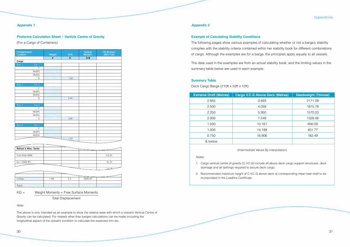
Appendix 2
Example of Calculating Stability Conditions
The following pages show various examples of calculating whether or not a barge’s stability
complies with the stability criteria contained within her stability book for different combinations
of cargo. Although the examples are for a barge, the principles apply equally to all vessels.
The data used in the examples are from an actual stability book, and the limiting values in the
summary table below are used in each example.
Summary Table
Deck Cargo Barge (210ft x 52ft x 12ft)
Extreme Draft (Metres) Cargo V.C.G Above Deck (Metres) Deadweight (Tonnes)
2.855 0.893 2171.09
2.500 4.058 1815.78
2.250 5.950 1570.03
2.000 7.548 1328.06
1.500 10.161 856.09
1.000 14.199 401.77
0.750 16.906 182.49
& below
(Intermediate Values By Interpolation)
Notes:
1. Cargo vertical centre of gravity (C.V.C.G) include all above deck cargo support structures, deckdunnage and all lashings required to secure deck cargo.
2. Recommended maximum height of C.V.C.G above deck at corresponding mean keel draft to beincorporated in the Loadline Certificate.
Appendicies
Appendix 1
Proforma Calculation Sheet – Verticle Centre of Gravity
(For a Cargo of Containers)
KG = Weight Moments + Free Surface Moments
Total Displacement
Note:
The above is only intended as an example to show the relative ease with which a vessel’s Vertical Centre ofGravity can be calculated. For vessels other than barges calculations can be made including thelongitudinal aspect of the vessel’s condition to calculate the expected trim etc.
3332
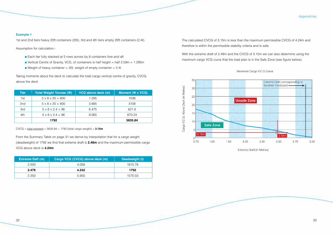
The calculated CVCG of 3.15m is less than the maximum permissible CVCG of 4.24m and
therefore is within the permissible stability criteria and is safe.
With the extreme draft of 2.48m and the CVCG of 3.15m we can also determine using the
maximum cargo VCG curve that the load plan is in the Safe Zone (see figure below).
Appendicies
Example 1
1st and 2nd tiers heavy 20ft containers (20t), 3rd and 4th tiers empty 20ft containers (2.4t).
Assumption for calculation:-
! Each tier fully stacked at 5 rows across by 8 containers fore and aft
! Vertical Centre of Gravity, VCG, of containers is half height = half 2.59m = 1.295m
! Weight of heavy container = 20t, weight of empty container = 2.4t
Taking moments about the deck to calculate the total cargo vertical centre of gravity, CVCG,
above the deck
Tier Total Weight Tonnes (W) VCG above deck (m) Moment (W x VCG)
1st 5 x 8 x 20 = 800 1.295 1036
2nd 5 x 8 x 20 = 800 3.885 3108
3rd 5 x 8 x 2.4 = 96 6.475 621.6
4th 5 x 8 x 2.4 = 96 9.065 870.24
1792 5635.84
CVCG = total moment = 5635.84 ÷ 1792 (total cargo weight) = 3.15m
From the Summary Table on page 31 we derive by interpolation that for a cargo weight
(deadweight) of 1792 we find that extreme draft is 2.48m and the maximum permissible cargo
VCG above deck is 4.24m
Extreme Daft (m) Cargo VCG (CVCG) above deck (m) Deadweight (t)
2.500 4.058 1815.78
2.476 4.242 1792
2.250 5.950 1570.03
3534
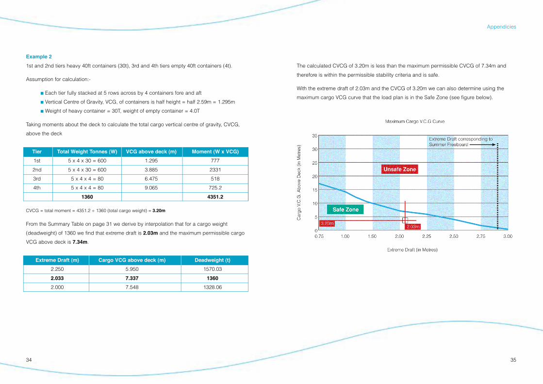
The calculated CVCG of 3.20m is less than the maximum permissible CVCG of 7.34m and
therefore is within the permissible stability criteria and is safe.
With the extreme draft of 2.03m and the CVCG of 3.20m we can also determine using the
maximum cargo VCG curve that the load plan is in the Safe Zone (see figure below).
Appendicies
Example 2
1st and 2nd tiers heavy 40ft containers (30t), 3rd and 4th tiers empty 40ft containers (4t).
Assumption for calculation:-
! Each tier fully stacked at 5 rows across by 4 containers fore and aft
! Vertical Centre of Gravity, VCG, of containers is half height = half 2.59m = 1.295m
! Weight of heavy container = 30T, weight of empty container = 4.0T
Taking moments about the deck to calculate the total cargo vertical centre of gravity, CVCG,
above the deck
Tier Total Weight Tonnes (W) VCG above deck (m) Moment (W x VCG)
1st 5 x 4 x 30 = 600 1.295 777
2nd 5 x 4 x 30 = 600 3.885 2331
3rd 5 x 4 x 4 = 80 6.475 518
4th 5 x 4 x 4 = 80 9.065 725.2
1360 4351.2
CVCG = total moment = 4351.2 ÷ 1360 (total cargo weight) = 3.20m
From the Summary Table on page 31 we derive by interpolation that for a cargo weight
(deadweight) of 1360 we find that extreme draft is 2.03m and the maximum permissible cargo
VCG above deck is 7.34m.
Extreme Draft (m) Cargo VCG above deck (m) Deadweight (t)
2.250 5.950 1570.03
2.033 7.337 1360
2.000 7.548 1328.06
36 37
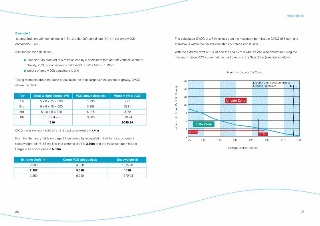
The calculated CVCG of 3.74m is less than the maximum permissible CVCG of 5.60m and
therefore is within the permissible stability criteria and is safe.
With the extreme draft of 2.30m and the CVCG of 3.74m we can also determine using the
maximum cargo VCG curve that the load plan is in the Safe Zone (see figure below)
Appendicies
Example 3
1st and 2nd tiers 20ft containers of (15t), 3rd tier 20ft containers (8t), 4th tier empty 20ft
containers (2.4t).
Assumption for calculation:-
! Each tier fully stacked at 5 rows across by 8 containers fore and aft Vertical Centre of
Gravity, VCG, of containers is half height = half 2.59m = 1.295m
! Weight of empty 20ft containers is 2.4t
Taking moments about the deck to calculate the total cargo vertical centre of gravity, CVCG,
above the deck
Tier Total Weight Tonnes (W) VCG above deck (m) Moment (W x VCG)
1st 5 x 8 x 15 = 600 1.295 777
2nd 5 x 8 x 15 = 600 3.885 2331
3rd 5 x 8 x 8 = 320 6.475 2072
4th 5 x 8 x 2.4 = 96 9.065 870.24
1616 6050.24
CVCG = total moment = 6050.24 ÷ 1616 (total cargo weight) = 3.74m
From the Summary Table on page 31 we derive by interpolation that for a cargo weight
(deadweight) of 1616T we find that extreme draft is 2.30m and the maximum permissible
Cargo VCG above deck is 5.60m
Extreme Draft (m) Cargo VCG above deck Deadweight (t)
2.500 4.058 1815.78
2.297 5.596 1616
2.250 5.950 1570.03
3938
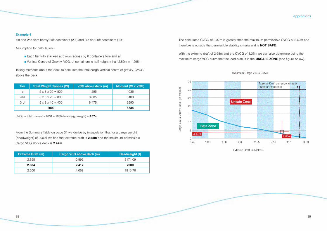
The calculated CVCG of 3.37m is greater than the maximum permissible CVCG of 2.42m and
therefore is outside the permissible stability criteria and is NOT SAFE.
With the extreme draft of 2.68m and the CVCG of 3.37m we can also determine using the
maximum cargo VCG curve that the load plan is in the UNSAFE ZONE (see figure below).
Appendicies
Example 4
1st and 2nd tiers heavy 20ft containers (20t) and 3rd tier 20ft containers (10t).
Assumption for calculation:-
! Each tier fully stacked at 5 rows across by 8 containers fore and aft
! Vertical Centre of Gravity, VCG, of containers is half height = half 2.59m = 1.295m
Taking moments about the deck to calculate the total cargo vertical centre of gravity, CVCG,
above the deck
Tier Total Weight Tonnes (W) VCG above deck (m) Moment (W x VCG)
1st 5 x 8 x 20 = 800 1.295 1036
2nd 5 x 8 x 20 = 800 3.885 3108
3rd 5 x 8 x 10 = 400 6.475 2590
2000 6734
CVCG = total moment = 6734 ÷ 2000 (total cargo weight) = 3.37m
From the Summary Table on page 31 we derive by interpolation that for a cargo weight
(deadweight) of 2000T we find that extreme draft is 2.68m and the maximum permissible
Cargo VCG above deck is 2.42m
Extreme Draft (m) Cargo VCG above deck (m) Deadweight (t)
2.855 0.893 2171.09
2.684 2.417 2000
2.500 4.058 1815.78
40 41
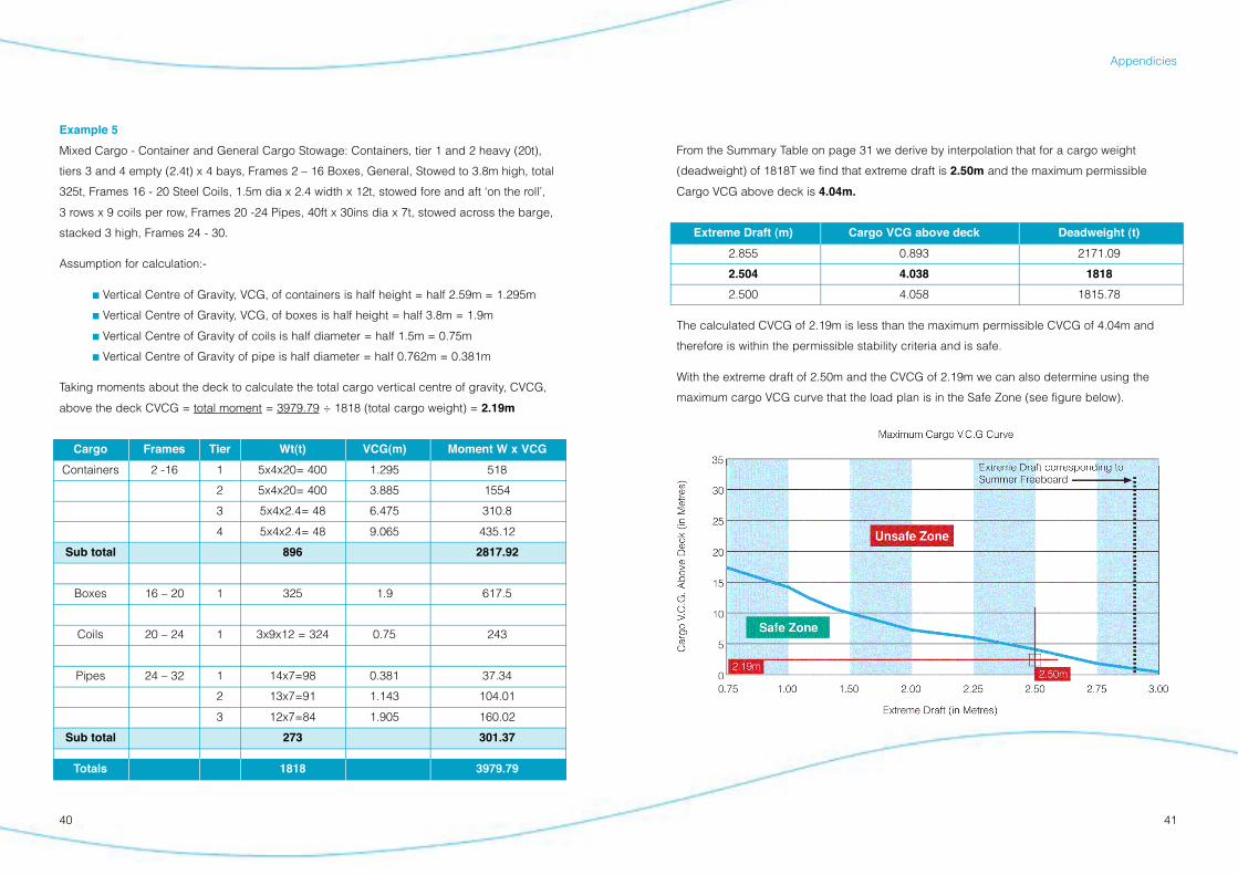
From the Summary Table on page 31 we derive by interpolation that for a cargo weight
(deadweight) of 1818T we find that extreme draft is 2.50m and the maximum permissible
Cargo VCG above deck is 4.04m.
Extreme Draft (m) Cargo VCG above deck Deadweight (t)
2.855 0.893 2171.09
2.504 4.038 1818
2.500 4.058 1815.78
The calculated CVCG of 2.19m is less than the maximum permissible CVCG of 4.04m and
therefore is within the permissible stability criteria and is safe.
With the extreme draft of 2.50m and the CVCG of 2.19m we can also determine using the
maximum cargo VCG curve that the load plan is in the Safe Zone (see figure below).
Appendicies
Example 5
Mixed Cargo - Container and General Cargo Stowage: Containers, tier 1 and 2 heavy (20t),
tiers 3 and 4 empty (2.4t) x 4 bays, Frames 2 – 16 Boxes, General, Stowed to 3.8m high, total
325t, Frames 16 - 20 Steel Coils, 1.5m dia x 2.4 width x 12t, stowed fore and aft ‘on the roll’,
3 rows x 9 coils per row, Frames 20 -24 Pipes, 40ft x 30ins dia x 7t, stowed across the barge,
stacked 3 high, Frames 24 - 30.
Assumption for calculation:-
! Vertical Centre of Gravity, VCG, of containers is half height = half 2.59m = 1.295m
! Vertical Centre of Gravity, VCG, of boxes is half height = half 3.8m = 1.9m
! Vertical Centre of Gravity of coils is half diameter = half 1.5m = 0.75m
! Vertical Centre of Gravity of pipe is half diameter = half 0.762m = 0.381m
Taking moments about the deck to calculate the total cargo vertical centre of gravity, CVCG,
above the deck CVCG = total moment = 3979.79 ÷ 1818 (total cargo weight) = 2.19m
Cargo Frames Tier Wt(t) VCG(m) Moment W x VCG
Containers 2 -16 1 5x4x20= 400 1.295 518
2 5x4x20= 400 3.885 1554
3 5x4x2.4= 48 6.475 310.8
4 5x4x2.4= 48 9.065 435.12
Sub total 896 2817.92
Boxes 16 – 20 1 325 1.9 617.5
Coils 20 – 24 1 3x9x12 = 324 0.75 243
Pipes 24 – 32 1 14x7=98 0.381 37.34
2 13x7=91 1.143 104.01
3 12x7=84 1.905 160.02
Sub total 273 301.37
Totals 1818 3979.79
42 43
Case Studies
4544
Observations:
Our investigations revealed that the cause of the loss was an error in calculating the vessel’s
stability. The Chief Officer had failed to make proper allowance for the height of a stow of
bagged cement in the lower hold when calculating the vessel’s vertical centre of gravity. As a
result his calculations produced an over-optimistic prediction of the vessel’s stability on
completion of loading. There was no established procedure on this ship for an independent
check of the Chief Officer’s calculation. Had there been one it is highly likely that the mistake
would have been noticed and the loss of the vessel avoided.
The Financial Cost:
Cargo claims totalling over US$3 million were submitted to the owners. By using package
limitation and defences available to the owners under the Hague Rules, those claims were
finally settled for less than US$500,000. The costs of removing the wreck of the vessel
approached US$1.5 million. Claims by the Port Authority and individual crew members
brought the total cost of the claim to almost US$2.2 million.
Case Studies
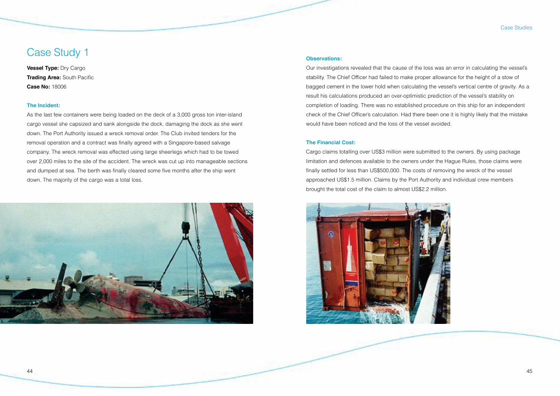
Case Study 1Vessel Type: Dry Cargo
Trading Area: South Pacific
Case No: 18006
The Incident:
As the last few containers were being loaded on the deck of a 3,000 gross ton inter-island
cargo vessel she capsized and sank alongside the dock, damaging the dock as she went
down. The Port Authority issued a wreck removal order. The Club invited tenders for the
removal operation and a contract was finally agreed with a Singapore-based salvage
company. The wreck removal was effected using large sheerlegs which had to be towed
over 2,000 miles to the site of the accident. The wreck was cut up into manageable sections
and dumped at sea. The berth was finally cleared some five months after the ship went
down. The majority of the cargo was a total loss.
4746
Case Studies
Investigations showed that the vessel had sustained two fractures in the tank top. These were
believed to have been caused by the heavy landing of containers during loading. The
problem was further exacerbated by the fact that the heeling tank filling pipe had corroded
through. Ironically therefore, ballast water used to correct the list increased the leakage into
the hold, aggravating the problem.
Observations:
The Master was criticised for not conducting a more thorough investigation at the time of the
initial listing.
A regular systematic daily sounding programme is a well established procedure of good
seamanship and would give an early indication of any problem. It would do away with the
need to engage in the dangerous practice of entering enclosed spaces to visually check the
Case Study 2Vessel Type: Feeder Container
Trading Area: Far East
Case No: 32771
The Incident:
This incident took place on a 25 year old 370 teu feeder container ship. Shortly before arriving
at the pilot station, an unexplained port list suddenly developed. The list was corrected and
“sounding round” showed there to be about 100 cm of water in her hold.
Until berthed, the vessel had flopped one way or another on a number of occasions, each
time corrected by moving ballast. Alongside she lay with a 15° list against the quay.
The Chief Officer carried out an assessment of the stability and deemed the vessel to be
unstable. The port authority subsequently refused to give permission for cargo operations to
commence until the vessel was upright, the cause of the listing was determined and stability
was confirmed by the Classification Society.
Efforts to pump out the hold bilge were thwarted by choked suctions. The services of a local
salvage company were engaged to pump out the hold and remove the top tier of containers in
order to regain positive stability. The ballast tanks were closely monitored during this operation
and it became apparent that water from two ballast tanks was entering the hold. The stability
calculations were reworked and showed the vessel to have positive stability. This was later
confirmed by the Classification Society.
Permission for cargo operations to commence was given nearly three days after the vessel’s
arrival at the port.
The Cause:
The incident was caused by free water in the cargo hold. Choked hold bilge suctions
prevented the water being pumped out by the ship’s staff.
4948
Case Studies
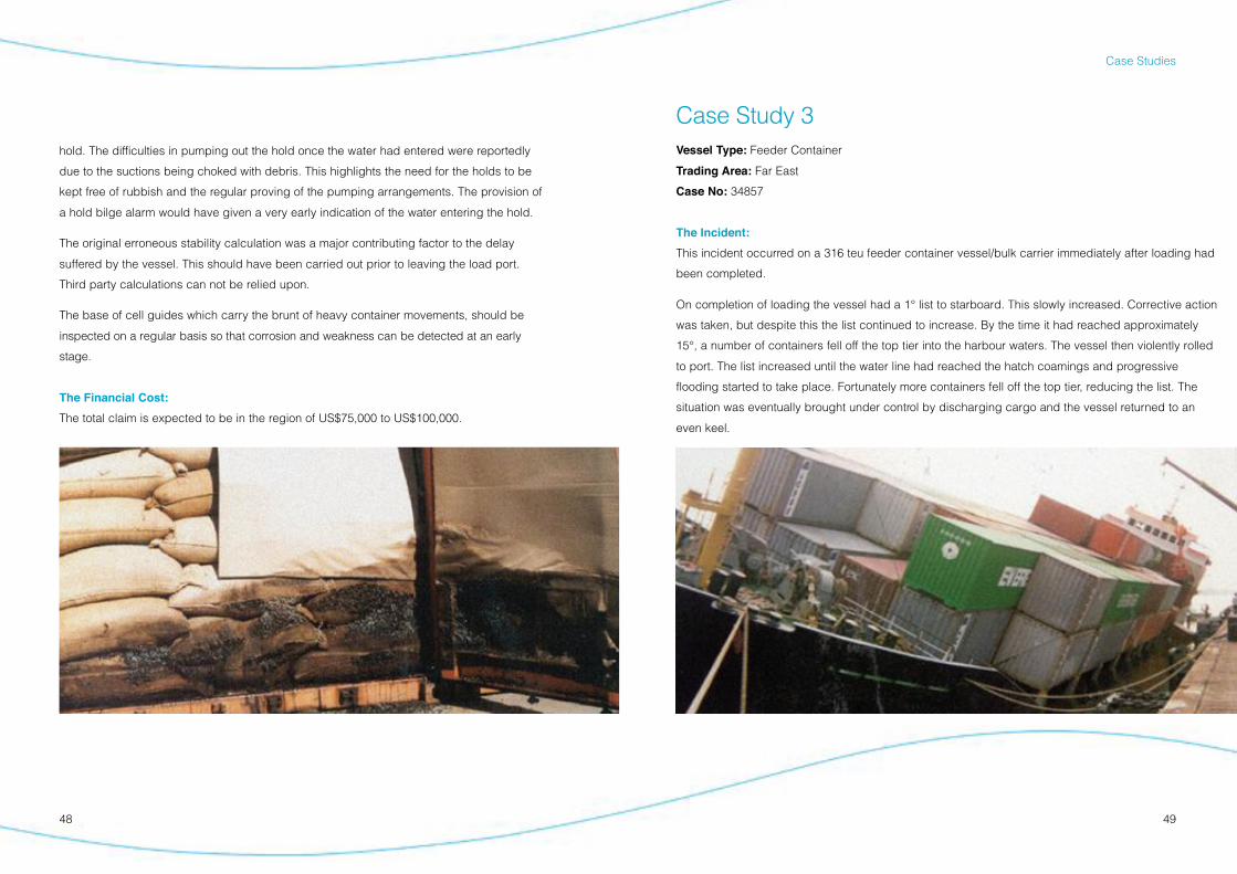
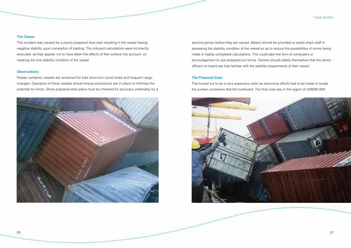
Case Study 3Vessel Type: Feeder Container
Trading Area: Far East
Case No: 34857
The Incident:
This incident occurred on a 316 teu feeder container vessel/bulk carrier immediately after loading had
been completed.
On completion of loading the vessel had a 1° list to starboard. This slowly increased. Corrective action
was taken, but despite this the list continued to increase. By the time it had reached approximately
15°, a number of containers fell off the top tier into the harbour waters. The vessel then violently rolled
to port. The list increased until the water line had reached the hatch coamings and progressive
flooding started to take place. Fortunately more containers fell off the top tier, reducing the list. The
situation was eventually brought under control by discharging cargo and the vessel returned to an
even keel.
hold. The difficulties in pumping out the hold once the water had entered were reportedly
due to the suctions being choked with debris. This highlights the need for the holds to be
kept free of rubbish and the regular proving of the pumping arrangements. The provision of
a hold bilge alarm would have given a very early indication of the water entering the hold.
The original erroneous stability calculation was a major contributing factor to the delay
suffered by the vessel. This should have been carried out prior to leaving the load port.
Third party calculations can not be relied upon.
The base of cell guides which carry the brunt of heavy container movements, should be
inspected on a regular basis so that corrosion and weakness can be detected at an early
s t a g e .
The Financial Cost:
The total claim is expected to be in the region of US$75,000 to US$100,000.
5150
Case Studies
second person before they are issued. Means should be provided to assist ship’s staff in
assessing the stability condition of the vessel so as to reduce the possibilities of errors being
made in hastily completed calculations. This could take the form of computers or
encouragement to use prepared pro forma. Owners should satisfy themselves that the senior
officers on board are fully familiar with the stability requirements of their vessel.
The Financial Cost:
This turned out to be a very expensive claim as enormous efforts had to be made to locate
the sunken containers that fell overboard. The final cost was in the region of US$580,000.
The Cause:
This incident was caused by a poorly prepared stow plan resulting in the vessel having
negative stability upon completion of loading. The onboard calculations were incorrectly
executed, as they appear not to have taken the effects of free surface into account, so
masking the true stability condition of the vessel.
Observations:
Feeder container vessels are renowned for their short turn round times and frequent cargo
changes. Operators of these vessels should ensure procedures are in place to minimise the
potential for errors. Shore prepared stow plans must be checked for accuracy, preferably by a
been taken of the numerous free surfaces in the ballast tanks. To make matters worse, it was
calculated that the vessel was in fact 400t over loaded, which resulted in her having a
freeboard of approximately 30cms less than the minimum permitted.
These factors combined to result in a drastic reduction of transverse stability which was
insufficient to withstand the forces created by the pushing tug. Ironically, the top tiers of
containers had not been secured but this allowed the containers to fall off and the vessel
returned to the upright. One of the contributing factors to the overloading was the under
declaration of the container weights by the shipper. This case highlights the need to monitor
the vessel’s condition at all times. By observing the drafts, the overloading would have been
noted at an early stage and the vessel’s lack of adequate stability detected.
Financial Cost:
The total cost of this claim was in excess of US$660,000; a great deal of this was accounted
for in recovering containers that sank in the approach channel to the berth.
52 53
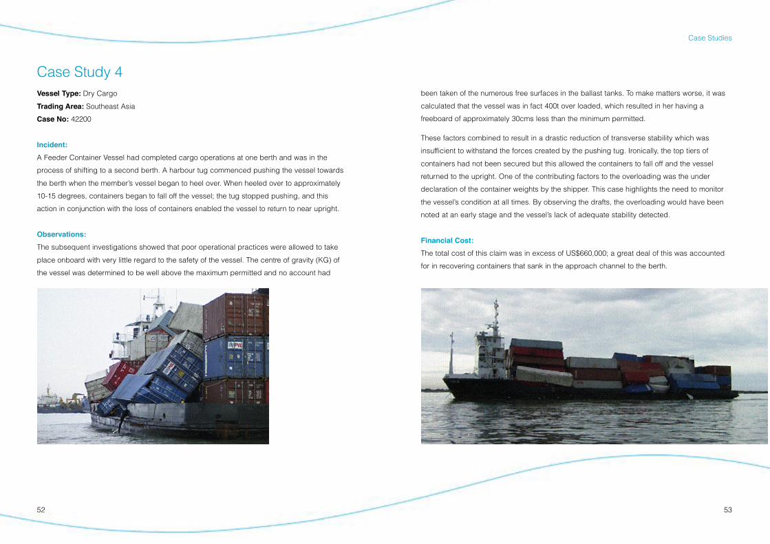
Case Study 4Vessel Type: Dry Cargo
Trading Area: Southeast Asia
Case No: 42200
Incident:
A Feeder Container Vessel had completed cargo operations at one berth and was in the
process of shifting to a second berth. A harbour tug commenced pushing the vessel towards
the berth when the member’s vessel began to heel over. When heeled over to approximately
10-15 degrees, containers began to fall off the vessel; the tug stopped pushing, and this
action in conjunction with the loss of containers enabled the vessel to return to near upright.
Observations:
The subsequent investigations showed that poor operational practices were allowed to take
place onboard with very little regard to the safety of the vessel. The centre of gravity (KG) of
the vessel was determined to be well above the maximum permitted and no account had
Case Studies


![Chapter 2 SiC Materials and Processing Technology€¦ · 34 2 SiC Materials and Processing Technology Table 2.1 Key electrical parameters of SiC [1] Property 4H-SiC 6H-SiC 3C-SiC](https://img.pdfslide.us/doc/110x75/5f4fd11797ddad63bf719816/chapter-2-sic-materials-and-processing-technology-34-2-sic-materials-and-processing.jpg)