Embed Size (px)
Citation preview

8/3/2019 B-2 Systems Engineering Case Studies
http://slidepdf.com/reader/full/b-2-systems-engineering-case-studies 1/118
B-2 Systems Engineering
Case Study
John M. Griffin, SES (Ret.)James E. Kinnu, Northrop-Grumman (Ret.)
Edited by John M. Colombi
Air Force Center for Systems Engineering
at the Air Force Institute of Technology
2950 Hobson Way, Wright-Patterson AFB OH 45433-7765
8/3/2019 B-2 Systems Engineering Case Studies
http://slidepdf.com/reader/full/b-2-systems-engineering-case-studies 2/118
Report Documentation PageForm Approved
OMB No. 0704-0188
Public reporting burden for the collection of information is estimated to average 1 hour per response, including the time for reviewing instructions, searching existing data sources, gathering and
maintaining the data needed, and completing and reviewing the collection of information. Send comments regarding this burden estimate or any other aspect of this collection of information,
including suggestions for reducing this burden, to Washington Headquarters Services, Directorate for Information Operations and Reports, 1215 Jefferson Davis Highway, Suite 1204, Arlington
VA 22202-4302. Respondents should be aware that notwithstanding any other provision of law, no person shall be subject to a penalty for failing t o comply with a collection of information if it
does not display a currently valid OMB control number.
1. REPORT DATE
2007 2. REPORT TYPE
3. DATES COVERED
00-00-2007 to 00-00-2007
4. TITLE AND SUBTITLE
B-2 Systems Engineering Case Study
5a. CONTRACT NUMBER
5b. GRANT NUMBER
5c. PROGRAM ELEMENT NUMBER
6. AUTHOR(S) 5d. PROJECT NUMBER
5e. TASK NUMBER
5f. WORK UNIT NUMBER
7. PERFORMING ORGANIZATION NAME(S) AND ADDRESS(ES)
Air Force Center for Systems Engineering,Air Force Institute of
Technology,2950 Hobson Way,Wright Patterson AFB,OH,45433-7765
8. PERFORMING ORGANIZATION
REPORT NUMBER
9. SPONSORING/MONITORING AGENCY NAME(S) AND ADDRESS(ES) 10. SPONSOR/MONITOR’S ACRONYM(S)
11. SPONSOR/MONITOR’S REPORT
NUMBER(S)
12. DISTRIBUTION/AVAILABILITY STATEMENT
Approved for public release; distribution unlimited
13. SUPPLEMENTARY NOTES
The original document contains color images.
14. ABSTRACT
15. SUBJECT TERMS 16. SECURITY CLASSIFICATION OF: 17. LIMITATION OF
ABSTRACT 18. NUMBER
OF PAGES
117
19a. NAME OF
RESPONSIBLE PERSON a. REPORT
unclassified
b. ABSTRACT
unclassified
c. THIS PAGE
unclassified
Standard Form 298 (Rev. 8-98)
Prescribed by ANSI Std Z39-18
8/3/2019 B-2 Systems Engineering Case Studies
http://slidepdf.com/reader/full/b-2-systems-engineering-case-studies 3/118
ii
PREFACE
In response to Air Force Secretary James G. Roche’s charge to reinvigorate the systemsengineering profession, the Air Force Institute of Technology (AFIT) undertook a broadspectrum of initiatives that included creating new instructional material. The Institute envisionedcase studies on past programs as one of these new tools for teaching the principles of systems
engineering.
Four case studies, the first set in a planned series, were developed with the oversight of the Subcommittee on Systems Engineering to the Air University Board of Visitors. TheSubcommittee included the following distinguished individuals:
Chairman
Dr. Alex Levis, AF/ST
Members
Brigadier General Tom Sheridan, AFSPC/DR
Dr. Daniel Stewart, AFMC/CD
Dr. George Friedman, University of Southern California
Dr. Andrew Sage, George Mason University
Dr. Elliot Axelband, University of Southern California
Dr. Dennis Buede, Innovative Decisions Inc.
Dr. Dave Evans, Aerospace Institute
Dr. Levis and the Subcommittee on Systems Engineering crafted the idea of publishingthese case studies, reviewed several proposals, selected four systems as the initial cases forstudy, and continued to provide guidance throughout their development. The Subcommittee’sleading minds in systems engineering have been a guiding force to charter, review, and approve
the work of the authors. The four case studies produced in that series were the C-5 Galaxy, theF-111, the Hubble Space Telescope, and the Theater Battle Management Core System.
This second series includes the B-2 Spirit Stealth bomber. Additional case studies areunder consideration for future publication in a third series.
Approved for Public Release; Distribution Unlimited
The views expressed in this Case Study are those of the author(s) and do not reflect the
official policy or position of the United States Air Force, the Department of Defense, or the
United States Government.

8/3/2019 B-2 Systems Engineering Case Studies
http://slidepdf.com/reader/full/b-2-systems-engineering-case-studies 4/118
iii
FOREWORD
At the direction of the Secretary of the Air Force, Dr. James G. Roche, the Air Forceestablished a Center for Systems Engineering (CSE) at the Air Force Institute of Technology(AFIT) campus on Wright-Patterson AFB, OH in 2002. With academic oversight by aSubcommittee on Systems Engineering, chaired by Air Force Chief Scientist Dr. Alex Levis, the
CSE was tasked to develop case studies focusing on the application of systems engineeringprinciples within various aerospace programs. The committee drafted an initial case outline andlearning objectives, and suggested the use of the Friedman-Sage Framework to guide overallanalysis.
The CSE contracted for management support with Universal Technology Corporation(UTC) in July 2003. Principal investigators for the four case studies published in the initialseries included Mr. John Griffin for the C-5A, Dr. G. Keith Richey for the F-111, Mr. JamesMattice for the Hubble Space Telescope, and Mr. Josh Collens from The MITRE Corporation forthe Theater Battle Management Core System effort. These cases were published in 2004 and areavailable on the CSE website.
The Department of Defense continues to develop and acquire joint complex systems thatdeliver needed capabilities demanded by our warfighters. Systems engineering is the technicaland technical management process that focuses explicitly on delivering and sustaining robust,high-quality, affordable products. The Air Force leadership, from the Secretary of the Air Force,to our Service Acquisition Executive, through the Commander of Air Force Materiel Command,has collectively stated the need to mature a sound systems engineering process throughout theAir Force.
Plans exist for future case studies focusing on other areas. Suggestions have includedother Joint service programs, logistics-led programs, science and technology/laboratory efforts,additional aircraft programs, and successful commercial systems.
As we uncovered historical facts and conducted key interviews with program managersand chief engineers, both within the government and those working for the various prime andsubcontractors, we concluded that systems programs face similar challenges today. Applicablesystems engineering principles and the effects of communication and the environment continueto challenge our ability to provide a balanced technical solution. We look forward to yourcomments on this B-2 case, our other AF CSE published studies, and others that will follow.
MARK K. WILSON, SES
Director, AF Center for Systems EngineeringAir Force Institute of Technologyhttp://cse.afit.edu/
8/3/2019 B-2 Systems Engineering Case Studies
http://slidepdf.com/reader/full/b-2-systems-engineering-case-studies 5/118
iv
PROLOGUE
The B-2 is a phenomenal weapon system… born out of the cold war as a strategic nuclearpenetrator... now proving it’s worth with a wide range of tactical precision weapon deliverycapabilities. This case study deals with the early Full Scale Development (FSD) and EngineeringManufacturing Development (EMD) phases of the program, known today as System Design and
Development (SDD)…there is a subtle but important difference…did you catch it? Hopefully, asyou work through this case study, you see that the System Engineering process applied on the B-2 program from 1979 (as the Advanced Technology Bomber requirements definition phase)through completion of the first airplane build played a significant role in bringing about thesuperior capability the system has today; not just in the design of the airplane, but also the in thedevelopment of new manufacturing processes as well.
I was privileged to serve as the Program Director from June 1983 (just as the decision toredesign the airplane was being made) to June 1991. There were a number of programmaticissues that faced the program throughout this time period; and without the Systems Engineeringprocess described in the case study, we would not have had the necessary quantitative data to beable to adequately address these programmatic issues in an authoritative way. The task of totallyredesigning the aircraft two years into the program, having completed Preliminary Deign Review#1, while striving to maintain, or minimize, program impacts was a Herculean task. Because of the System Engineering process discussed in this case study, with the discipline and integrity thatexisted in the process, the B-2 Program was able to maintain the technical baseline across theentire government/contractor team and by so doing minimized the eventual impacts. The keyfactor in accomplishing this, after the professionalism and dedication of all the people involved,was the fact that the program had only ONE (near real time) design data base; which all of theprogram participants utilized…engineering, manufacturing, test, sub-contractors, and thegovernment. As System Engineers, and particularly as Chief System Engineers, maintaining thetechnical baseline will be the most important part of your job… without it, the programmaticimpacts will begin to accumulate to the point where the program will eventually become at risk.
I want to emphasize at this point that there is a difference between System Engineeringroles and responsibilities and Program Management roles and responsibilities… both areimportant to the success of a program… but Program Directors can not succeed without a soundtechnical baseline and a solid System Engineering process. The most important responsibility forthe System Engineer is to maintain the integrity of the technical baseline, regardless of programmatic issues; because it is absolutely fundamental to the integrity of the program
management baseline.
Richard M. Scofield, Lt Gen, USAF, Ret

8/3/2019 B-2 Systems Engineering Case Studies
http://slidepdf.com/reader/full/b-2-systems-engineering-case-studies 6/118
v
ACKNOWLEDGEMENTS
The authors would like to acknowledge the special contributions of people who dedicatedtheir time and energy to make this report accurate and complete. We offer our sincereappreciation to all the people listed in Appendix 3, who volunteered their time and insight duringthe interviews. Very special thanks go to Lauren Proffit, Universal Technology Corporation,
without whom we could ever have finished the editing and formatting of the report. Heartfeltcongratulations to all the people involved in the program and particularly the systems engineersand design engineers at Northrop, Boeing, Vought, the vendors, WPAFB, Strategic AirCommand, and EAFB for their tireless efforts in delivering this truly outstanding capability thathas served our nation so well.
Additional special thanks to those no longer with us; Leonard Rose, Northrop B-2 Chief Engineer; Dave England, Col, USAF, ASD/XRJ program manager; John Paterno, Northrop vicepresident, B-2 Division. Great leaders, great men, they are missed.
We also provide a special thank you and note of appreciation to our AFIT Project Leader,Lt Col John M. Colombi, who provided editorial guidance to the authors, along with continuous
motivation.
John M. GriffinJames E. Kinnu
8/3/2019 B-2 Systems Engineering Case Studies
http://slidepdf.com/reader/full/b-2-systems-engineering-case-studies 7/118
vi
EXECUTIVE SUMMARY
The B-2 Systems Engineering Case Study describes the application of systemsengineering during the concept exploration, design, and development of the USAF B-2 Spiritstealth bomber. The case examines and explores the systems engineering process as applied bythe Air Force B-2 System Program Office, the prime contractor, Northrop, and the two major
subcontractors, Boeing and Vought, from the program’s genesis in the late 1970s to the firstflight of the first aircraft on 17 July 1989. The systems engineering process is traced from avision of a few planners in 1978 to the production of 21 operational aircraft that are currentlyserving our nation. Numerous interviews were conducted with the principals who managed anddirected the program and a story of the systems engineering process emerged.
The B-2 was conceived to profit from the advances in stealth technology that grew from aseries of laboratory experiments and design studies during 1970 to 1976. The early work by boththe government and industry during this timeframe resulted in feasible and practical stealthvehicles that exist throughout our military. The current operational fleets of fighters, bombers,UAVs, ships, and other stealth vehicles trace their heritage to the early technology maturationand engineering development programs. Stealth (or low observables, as it was called by theoriginal practitioners) offered a new and revolutionary approach for penetrating the burgeoninggrowth of the Soviet defensive system of an integrated radar network. The fighter was the firsttype of weapon system to be studied for the benefits of stealth and the pay-off was assessed assubstantial. The bomber was the next obvious candidate, and it too, showed great promise.Lockheed was in the lead for the technology application for fighters and was awarded thedevelopment contract for the F-117 stealth fighter. Northrop and Lockheed were competitors forthe contract to develop the stealth bomber from late 1979; Northrop won the contract inNovember 1981. The first flight of the B-2 was 17 July 1989 with the first operational sortie of the aircraft occurring during the Balkan conflict in December 1995.
The Spirit is a long-range heavy bomber incorporating the key technologies of the time.
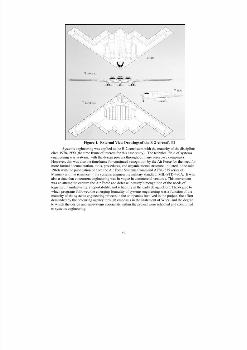
First, as evident in Figure 1, it is a highly efficient flying-wing (tailless) aeronautical design.Secondly, the aircraft makes extensive use of composite materials. And third, it is designed forstealth. Figure 1 shows four views of the aircraft with each view showing the details of thecontrol surfaces, doors, access panels, and other external features. Note the center of the aircraftfrom the bottom view, showing the large cut out of the structure to accommodate the weaponsbay doors (4), engine access doors (4), and the main landing gear doors (2). The ability toachieve an efficient structural design in the presence of the large cutouts on the bottom skin of the vehicle is one of the significant achievements of the structures team.
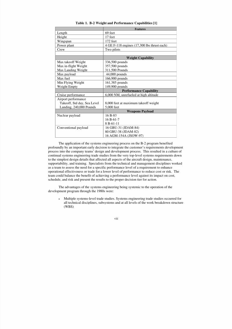
The B-2 has significant range performance and payload capability. Table 1 shows thedesign weights and the range and payloads for the nuclear mission as well as the conventional
missions. The bomber was primarily designed as a long-range strategic nuclear delivery system,but a significant conventional capability was designed in from the beginning. The table showsan abbreviated list of weapons currently certified for carriage. The list of weapons carriagecapability continues to expand through ongoing B-2 modernization programs.
8/3/2019 B-2 Systems Engineering Case Studies
http://slidepdf.com/reader/full/b-2-systems-engineering-case-studies 8/118
vii
Figure 1. External View Drawings of the B-2 Aircraft [1]
Systems engineering was applied to the B-2 consistent with the maturity of the disciplinecirca 1978-1990 (the time frame of interest for this case study). The technical field of systemsengineering was systemic with the design process throughout many aerospace companies.However, this was also the timeframe for continued recognition by the Air Force for the need formore formal documentation, tools, procedures, and organizational structure, initiated in the mid1960s with the publication of both the Air Force Systems Command AFSC-375 series of Manuals and the issuance of the systems engineering military standard, MIL-STD-490A. It wasalso a time that concurrent engineering was in vogue in commercial ventures. This movementwas an attempt to capture the Air Force and defense industry’s recognition of the needs of logistics, manufacturing, supportability, and reliability in the early design effort. The degree towhich programs followed the emerging formality of systems engineering was a function of thematurity of the systems engineering process in the companies involved in the project, the effortdemanded by the procuring agency through emphasis in the Statement of Work, and the degreeto which the design and subsystems specialists within the project were schooled and committedto systems engineering.
8/3/2019 B-2 Systems Engineering Case Studies
http://slidepdf.com/reader/full/b-2-systems-engineering-case-studies 9/118
viii
Table 1. B-2 Weight and Performance Capabilities [1]
The application of the systems engineering process on the B-2 program benefitedprofoundly by an important early decision to integrate the customer’s requirements developmentprocess into the company teams’ design and development process. This resulted in a culture of continual systems engineering trade studies from the very top-level systems requirements downto the simplest design details that affected all aspects of the aircraft design, maintenance,supportability, and training. Specialists from the technical and management disciplines workedas a team to assess the need for a specific performance level of a requirement to enhanceoperational effectiveness or trade for a lower level of performance to reduce cost or risk. Theteam could balance the benefit of achieving a performance level against its impact on cost,schedule, and risk and present the results to the proper decision tier for action.
The advantages of the systems engineering being systemic to the operation of thedevelopment program through the 1980s were:
• Multiple systems-level trade studies. Systems engineering trade studies occurred forall technical disciplines, subsystems and at all levels of the work breakdown structure(WBS)
Features
Length 69 feet
Height 17 feet
Wingspan 172 feet
Power plant 4 GE F-118 engines (17,300 lbs thrust each)Crew Two pilots
Weight Capability
Max takeoff WeightMax in-flight WeightMax Landing Weight
336,500 pounds357,500 pounds311,500 Pounds
Max payload 44,000 pounds
Max fuel 166,900 pounds
Min Flying WeightWeight Empty
161,385 pounds149,900 pounds
Performance Capability
Cruise performance 6,000 NM, unrefueled at high altitude
Airport performanceTakeoff, Std day, Sea LevelLanding, 240,000 Pounds
8,000 feet at maximum takeoff weight5,000 feet
Weapons Payload
Nuclear payload 16 B-8316 B-61-78 B-61-11
Conventional payload 16 GBU-31 (JDAM-84)
80 GBU-38 (JDAM-82)16 AGM-154A (JSOW-97)
8/3/2019 B-2 Systems Engineering Case Studies
http://slidepdf.com/reader/full/b-2-systems-engineering-case-studies 10/118
ix
• Balanced performance, cost, schedule, and risk
• Agreement on the tasks to be performed and their priority
• Well understood and documented customer/supplier agreements.
In order to take advantage of the benefits that accrued from the integration of therequirements and the design/development processes, other program initiatives and decisionsmaking process were crucial, including:
• Rapid decision process with the ability to get the proper information to the properlevel, followed by timely action
• An organizational structure that utilized a system view to assess impacts
• Skilled professionals at all levels and in all technical and management disciplines
• Processes to accurately assess, assign, track, integrate, and close risks.
The organizational structures at the contractors (Northrop, Boeing, Vought, Hughes,General Electric, etc.) and government agencies (Aeronautical Systems Division, the B-2Program Office, and the Strategic Air Command) were critical to the success of the program.The Air Force Systems Program Office (SPO) organization was a “classic” functional structurewith a strong integration process that utilized the top two levels of the organization as theprimary programmatic decision-making body. The contractors used a combination of strongproject offices, along wit functional organizations to provide the decision base and the leadershipfor the program.
There were several different systems engineering organizations in each major functionalorganization. The workforce was arranged in WBS task teams, similar in construct to the
Integrated Product Teams (IPT) to follow in the future, but with some fundamental differences.These WBS task teams were the critical functioning structure and were the primary process bywhich business was conducted throughout the development program. Risk Closure Plans were akey management process and were instrumental in providing focus to risk identification,tracking, and closure. Thus, the organizational structure, the WBS task team construct, thedecision making process, the risk closure planning process, the systems engineering tools, andthe dedicated, talented, experienced people in engineering, all the functional areas, and programmanagement were essential features of the systems engineering process during the developmentprocess of the B-2.
The Five B-2 Learning Principles
The learning principles are those key factors that the authors considered as the mostinfluential to the successful outcomes and to the failures of the program. They are developed infurther detail, by following the chronological evolution of the program. In Section 4, thelearning principles are then summarized and further emphasized as to why they were chosen asthe major points.
LP 1, Integration of the Requirements and Design Processes: A key aspect of theimplementation of the systems engineering process was the integration of the SPOrequirement’s team with the contractors’ work breakdown structure (WBS) Task
8/3/2019 B-2 Systems Engineering Case Studies
http://slidepdf.com/reader/full/b-2-systems-engineering-case-studies 11/118
x
teams into a cohesive program effort. These contractor teams included design,manufacturing, Quality Assurance, and logistics. This integration facilitated continualtrade studies conducted by the specialists from the User/SPO government team withthe company specialists to fully assess the performance trade-offs against schedule,cost, and risk.
LP 2, WBS Task Teams and Functional Hierarchy: A well-defined contract work breakdown structure (WBS) stipulated the entire program content and tasking. Thecompany organized the design/development effort into multiple teams, responsible toimplement the WBS for sections of the air vehicle and for each subsystem. TheseWBS Task Teams were assigned complete work packages, for example, the forwardcenter wing. The systems engineering WBS Task Team efforts were organizedsimilarly, but with separate responsibilities, each reporting to the Northrop chief engineer or his deputies. The functional organizations assigned members to the task teams to assure accommodation of their program needs. A vital distinction frommany of today’s IPTs was retaining the WBS Task Team membership throughout thefunctional organizations’ various management levels. This facilitated
communication, integration, interfaces, and integrated the functional leadership of each of the company’s technical and management disciplines into the decisionprocess. The program management top-level structure was organized into a strongproject office with centralized decision authority and strong leadership at the top of both the SPO and the contractor organizations.
LP 3, Air Vehicle Reconfiguration: When the identification of a major aeronauticalcontrol inadequacy was discovered just four months prior to formal configurationfreeze, an immediate refocus of the Task Teams was required. Within several days,the air vehicle task teams were conducting trade studies, augmenting their skill sets,and integrating with the other program participants in a coordinated effort to derivean efficient, controllable, operationally useful system. At the same time, the programelements that were not markedly affected by the change maintained a course thatpreserved their schedule, but was sufficiently flexible to include any potentialchanges. In a program wide systems engineering effort, the prime contractor’sprogram office integrated the teams, reviewed their efforts, coordinated the systemstrades, and identified significant changes to the outer mode lines, the radar crosssection (RCS) baseline, all major structure assemblies, and all major air vehiclesubsystems requirements, with the exception of avionics and armament. Thealternatives were derived by the end of the third month, the final choice was selectedby the sixth month, and the seventh month was used to coordinate and garner theapproval of all stakeholders. While the program response to the crisis was rapid andeffective, and a significant impact on the downstream cost and schedule was
anticipated by the management team, and the technical impact was predicted by thesystems engineering process, it was not predicted to the fullest extent.
LP 4, Subsystem Maturity: The effect of the reconfiguration on the maturity of all the airvehicle subsystems (flight control, environmental control, electrical, landing gear,etc) was far greater than projected. The subsystems were mostly vendor-suppliedequipments and some were in the selection process to the technical requirements of the original baseline when the reconfiguration occurred. After the new configuration
8/3/2019 B-2 Systems Engineering Case Studies
http://slidepdf.com/reader/full/b-2-systems-engineering-case-studies 12/118
xi
was derived, the requirements for the subsystems changed to such a degree that theyhad to be resized and repackaged. It took longer than anticipated by the systemsengineering process to recognize the growing problem of getting all the specificationsupdated and to identify the lagging equipment maturity that resulted. Thus, thereconfiguration required a second iteration of the design requirements and their flow-
down to the many suppliers and their detailed designs. These iterations after PDR-2resulted in the vehicle subsystems not achieving their Critical Design Review (CDR)milestone concurrently with the structure, but rather five months later.
LP 5, Risk Planning and Management: The program was structured so that risksaffecting the viability of the weapons system concept were identified at contractaward and were structured as part of the Program and WBS work plans. The initialrisks were comprised of those “normal” risks associated with a large complexweapons system development as well as the new technology and processes necessaryto mature the program to low to medium risk at PDR. Those initial risks were closedprior to PDR 2. The risk closure process continued throughout development andidentified new risks and continuously identified new risk closure plans. Most
importantly, the work associated with risk closure for each plan was integrated intothe WBS task teams’ work plans and into the Program Plans. These detailed plansshowed all design, analyses, tests, tooling, and other tasks necessary to close theidentified risks and were maintained as part of the normal design/program reportingactivity.
The Friedman-Sage [2] Framework was used to examine the context of all the learningprinciples, their primary responsibility and their overall effect on the program. The Friedman-Sage construct and its associated matrix of nine Concept Domains and Three ResponsibilityDomains gives the systems engineering practitioner a powerful tool to examine a program’ssystems engineering effort.
As the reader delves into the full story of the B-2, it is important to keep in mind theenvironment surrounding the program. Conducted in utmost secrecy, it can be compared to theManhattan Project of WWII that developed the atomic bomb. Security was the most importantconsideration. In fact, the Program Management Directive (PMD) specified the order of program priority as:
1. Security
2. Performance
3. Schedule, and
4. Cost.
The program was part of the Reagan weapons build-up, along with the B-1B and PeacekeeperMissile System in the early 1980s. This build-up can be considered to have caused the instabilityin the Soviet Union that eventually led to the collapse of that country and the end of the ColdWar on 9 November 1989 with the fall of the Berlin Wall.
8/3/2019 B-2 Systems Engineering Case Studies
http://slidepdf.com/reader/full/b-2-systems-engineering-case-studies 13/118
xii
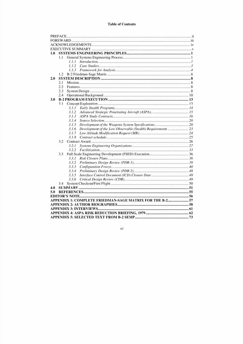
Table of Contents
PREFACE....................................................................................................................................... iiFOREWARD................................................................................................................................. iii
ACKNOWLEDGEMENTS........................................................................................................... ivEXECUTIVE SUMMARY .............................................................................................................v1.0 SYSTEMS ENGINEERING PRINCIPLES...................................................................... 1
1.1 General Systems Engineering Process.......................................................................... 1 1.1.1 Introduction..................................................................................................... 1 1.1.2 Case Studies.................................................................................................... 3 1.1.3 Framework for Analysis.................................................................................. 4
1.2 B-2 Friedman-Sage Matrix ........................................................................................... 6 2.0 SYSTEM DESCRIPTION .................................................................................................. 8
2.1 Mission.......................................................................................................................... 8 2.2 Features......................................................................................................................... 8 2.3 System Design .............................................................................................................. 8 2.4 Operational Background ............................................................................................. 10
3.0 B-2 PROGRAM EXECUTION........................................................................................ 13 3.1 Concept Exploration ................................................................................................... 13
3.1.1 Early Stealth Programs................................................................................. 14 3.1.2 Advanced Strategic Penetrating Aircraft (ASPA)......................................... 15 3.1.3 ASPA Study Contracts................................................................................... 16 3.1.4 Source Selection............................................................................................ 20 3.1.5 Development of the Weapons System Specifications .................................... 20 3.1.6 Development of the Low Observable (Stealth) Requirements ...................... 23 3.1.7 Low Altitude Modification Request (MR) ..................................................... 24 3.1.8 Contract schedule ......................................................................................... 25
3.2 Contract Award........................................................................................................... 26 3.2.1 Systems Engineering Organizations ............................................................. 27 3.2.2 Facilitization................................................................................................. 33
3.3 Full Scale Engineering Development (FSED) Execution........................................... 36 3.3.1 Risk Closure Plans........................................................................................ 36 3.3.2 Preliminary Design Review (PDR-1)............................................................ 39 3.3.3 Configuration Freeze.................................................................................... 40 3.3.4 Preliminary Design Review (PDR-2)............................................................ 48 3.3.5 Interface Control Document (ICD) Closure Date ........................................ 49 3.3.6 Critical Design Review (CDR)...................................................................... 49
3.4 System Checkout/First Flight ..................................................................................... 50 4.0 SUMMARY ........................................................................................................................ 51 5.0 REFERENCES................................................................................................................... 55 EDITOR’S NOTE....................................................................................................................... 56 APPENDIX 1: COMPLETE FRIEDMAN-SAGE MATRIX FOR THE B-2....................... 57 APPENDIX 2: AUTHOR BIOGRAPHIES.............................................................................. 58 APPENDIX 3: INTERVIEWS................................................................................................... 61 APPENDIX 4: ASPA RISK REDUCTION BRIEFING, 1979............................................... 62 APPENDIX 5: SELECTED TEXT FROM B-2 SEMP........................................................... 73
8/3/2019 B-2 Systems Engineering Case Studies
http://slidepdf.com/reader/full/b-2-systems-engineering-case-studies 14/118
8/3/2019 B-2 Systems Engineering Case Studies
http://slidepdf.com/reader/full/b-2-systems-engineering-case-studies 15/118
1
1.0 SYSTEMS ENGINEERING PRINCIPLES
1.1 General Systems Engineering Process
1.1.1 Introduction
The Department of Defense continues to develop and acquire systems to provide needed
capabilities to the warfighter. With a constant objective to improve the acquisition process, itstrives at new and creative ways to acquire these technically complex systems. A sound systemsengineering process, focused explicitly on delivering and sustaining robust, high-quality,affordable products that meet the needs of customers and stakeholders must continue to evolveand mature. Systems engineering is the technical and technical management process that resultsin delivered products and systems that exhibit the best balance of cost, schedule, andperformance. The process must operate effectively with desired mission-level capabilities,establish system-level requirements, allocate these down to the lowest level of the design, andassure validation and verification of performance, meeting cost and schedule constraints. Thesystems engineering process changes as the program progresses from one phase to the next, as dothe tools and procedures. The process also changes over the decades, maturing, expanding,
growing, and evolving from the base established during the conduct of past programs. Systemsengineering has a long history. Examples can be found demonstrating a systemic application of effective engineering and engineering management, as well as poorly applied, but well definedprocesses. Throughout the many decades during which systems engineering has emerged as adiscipline, many practices, processes, heuristics, and tools have been developed, documented,and applied.
Several core lifecycle stages have surfaced as consistently and continually challengingduring any system program development. First, system development must proceed from a well-developed set of requirements. Secondly, regardless of the evolutionary acquisition approach,the system requirements must flow down to all subsystems and lower level components. Andthird, the system requirements need to be stable, balanced and must properly reflect all activities
in all intended environments. However, system requirements are not unchangeable. As thesystem design proceeds, if a requirement or set of requirements is proving excessively expensiveto satisfy, the process must rebalance schedule, cost, and performance by changing or modifyingthe requirements or set of requirements.
Systems engineering includes making key system and design trades early in the processin order to establish the system architecture. These architectural artifacts can depict any newsystem, legacy system, modifications thereto, introduction of new technologies, and overallsystem-level behavior and performance. Modeling and simulation are generally employed toorganize and assess architectural alternatives at this introductory stage. System and subsystemdesign follows the functional architecture. System architectures are modified if the elements are
too risky, expensive or time-consuming. Both newer object-oriented analysis and design andclassic structured analysis using functional decomposition and information flows/data modelingoccurs. Design proceeds logically using key design reviews, tradeoff analysis, and prototypingto reduce any high-risk technology areas [3, Colombi].
Important to the efficient decomposition and creation of the functional and physicalarchitectures and designs are the management of interfaces and integration of subsystems. Thisis applied to subsystems within a system, or across large, complex systems of systems. Once asolution is planned, analyzed, designed, and constructed, validation and verification take place to
8/3/2019 B-2 Systems Engineering Case Studies
http://slidepdf.com/reader/full/b-2-systems-engineering-case-studies 16/118
2
assure the requirements have been satisfied. Definition of test criteria, measures of effectiveness(MOEs), and measures of performance (MOPs), established as part of the requirements process,take place well before any component or subsystem assembly design and construction occurs.
There are several excellent representations of the systems engineering process presentedin the literature. These depictions present the current state of the art in the maturity and
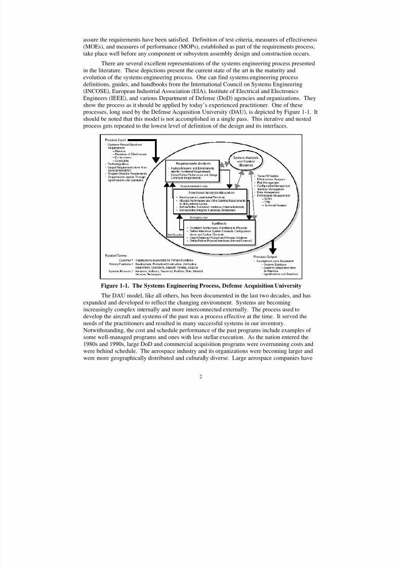
evolution of the systems engineering process. One can find systems engineering processdefinitions, guides, and handbooks from the International Council on Systems Engineering(INCOSE), European Industrial Association (EIA), Institute of Electrical and ElectronicsEngineers (IEEE), and various Department of Defense (DoD) agencies and organizations. Theyshow the process as it should be applied by today’s experienced practitioner. One of theseprocesses, long used by the Defense Acquisition University (DAU), is depicted by Figure 1-1. Itshould be noted that this model is not accomplished in a single pass. This iterative and nestedprocess gets repeated to the lowest level of definition of the design and its interfaces.
Figure 1-1. The Systems Engineering Process, Defense Acquisition University
The DAU model, like all others, has been documented in the last two decades, and hasexpanded and developed to reflect the changing environment. Systems are becomingincreasingly complex internally and more interconnected externally. The process used todevelop the aircraft and systems of the past was a process effective at the time. It served theneeds of the practitioners and resulted in many successful systems in our inventory.Notwithstanding, the cost and schedule performance of the past programs include examples of some well-managed programs and ones with less stellar execution. As the nation entered the1980s and 1990s, large DoD and commercial acquisition programs were overrunning costs andwere behind schedule. The aerospace industry and its organizations were becoming larger andwere more geographically distributed and culturally diverse. Large aerospace companies have
8/3/2019 B-2 Systems Engineering Case Studies
http://slidepdf.com/reader/full/b-2-systems-engineering-case-studies 17/118
3
worked diligently to establish common systems engineering practices across their enterprises.However, these common practices must be understood and be useful to the enterprise and acrossmultiple corporations because of the mega-trend of teaming in large (and some small) programs.It is essential that the systems engineering process effect integration, balance, allocation, andverification and be useful to the entire program team down to the design and interface level.
Today, many factors overshadow new acquisition, including the system-of-systems (SoS)context, network centric warfare and operations, and the rapid growth in information technology.These factors are driving a more sophisticated systems engineering process with more complexand capable features, along with new tools and procedures. One area of increased focus of thesystems engineering process is the information systems architectural definitions used duringsystem analysis. This process, described in the DoD Architectural Framework (DoDAF) [4],emphasizes greater reliance on reusable architectural views describing the system context,concept of operations, interoperability, information and data flows and network service-orientedcharacteristics.
1.1.2 Case Studies
The systems engineering process to be used in today’s complex systems and system-of-systems projects is a process matured and founded on principles developed in the past.Examination of systems engineering principles used on programs, both past and present, canprovide a wealth of lessons to be used in applying and understanding today’s process. It was thisthinking that led to the construction of the AF CSE case studies.
The purpose of developing detailed case studies is to support the teaching of systemsengineering principles. They will facilitate learning by emphasizing to the student the long-termconsequences of the systems engineering as it influences program decisions, thereby influencingprogram success. Systems engineering case studies assist in discussion of both successful andunsuccessful methodologies, processes, principles, tools, and decision material to assess theoutcome of alternatives at the program/system level. In addition, the importance of using skills
from logistics, manufacturing, finance, contracts, Quality Assurance, and engineering disciplinesand then collecting, assessing, and integrating varied functional data are emphasized. When theyare taken together, the student is provided real-world detailed examples of how the processcontributes to the effective balance of cost, schedule, and performance.
The utilization and mis-utilization of systems engineering principles are highlighted, withspecial emphasis on the conditions that both foster and impede good systems engineeringpractice. Case studies should be used to illustrate both good and bad examples of acquisitionmanagement and learning principles, to include whether:
• Every system provides a satisfactory balanced and effective product to a customer• Effective requirements analysis was applied• Consistent and rigorous application of systems engineering management standards
was applied• Effective test planning was accomplished• There were effective major technical program reviews• Continuous risk assessments and management was implemented• There were reliable cost estimates and policies• They used disciplined application of configuration management• A well defined system boundary was defined
8/3/2019 B-2 Systems Engineering Case Studies
http://slidepdf.com/reader/full/b-2-systems-engineering-case-studies 18/118
4
• They used disciplined methodologies for complex systems• Problem solving incorporated understanding of the system within bigger environment
(customer’s customer)
The systems engineering process transforms an operational need into a system or system-of-systems. Architectural elements of the system are allocated and translated into detailed design
requirements by the systems engineering process. The systems engineering process, from theidentification of the operational need, through the development, and to utilization of the product,must continuously integrate and balance the requirements, while giving consideration to the costand schedule to provide an operationally effective system throughout its lifecycle. Systemsengineering case studies highlight the various interfaces and communications to achieve thisbalance, which include:
• The program manager/systems engineering interface essential between theoperational user and developer (acquirer) to translate the needs into the performancerequirements for the system and subsystems.
• The government/contractor interface essential for the practice of systems engineeringto translate and allocate the performance requirements into detailed requirements.
• The developer (acquirer)/industry/user interface within the project, essential for thesystems engineering practice of integration and balance.
The systems engineering process must manage risk, both known and unknown, as well asboth internal and external. Identifying, integrating, and managing the internal risks within thescope of the directed program is an essential task of the systems engineering process. A secondresponsibility of the process is to quickly and accurately respond when asked to evaluateproposed changes to the directed program, external risks. The process must advise the programdecision makers as to the consequences of proposed changes that may be imposed by externalforces. The objective of this second responsibility will specifically capture those external factorsand the impact of these uncontrollable influences, such as actions of Congress, changes in
funding, new instructions/policies, changing stakeholders or user requirements or contractor andgovernment staffing levels.
Lastly, the systems engineering process must respond to “Mega-Trends” in the systemsengineering discipline itself, as the nature of systems engineering and related practices do varywith time and circumstances.
1.1.3 Framework for Analysis
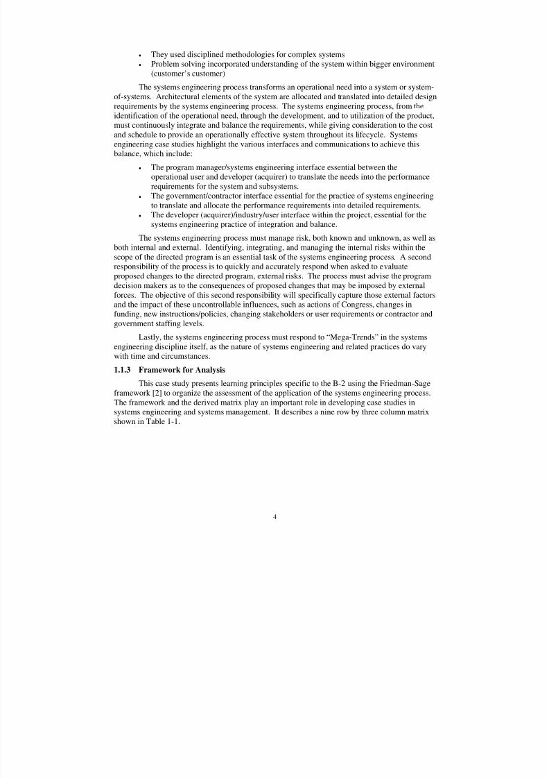
This case study presents learning principles specific to the B-2 using the Friedman-Sageframework [2] to organize the assessment of the application of the systems engineering process.The framework and the derived matrix play an important role in developing case studies insystems engineering and systems management. It describes a nine row by three column matrix
shown in Table 1-1.
8/3/2019 B-2 Systems Engineering Case Studies
http://slidepdf.com/reader/full/b-2-systems-engineering-case-studies 19/118
5
Table 1-1. A Framework of Key Systems Engineering Concepts and Responsibilities [2]
Concept Domain Responsibility Domain
1. Contractor
Responsibility
2. Shared
Responsibility
3. Government
Responsibility
A. Requirements Definition andManagement
B. Systems Architecting and ConceptualDesign
C. System and Subsystem DetailedDesign and Implementation
D. Systems and Interface Integration
E. Validation and Verification
F. Deployment and Post Deployment
G. Life Cycle Support
H. Risk Assessment and Management
I. System and Program Management
Six of the nine concept domain areas in Table 1-1 represent phases in the systemsengineering lifecycle:
A. Requirements Definition and Management
B. Systems Architecting and Conceptual Design
C. Detailed System and Subsystem Design and Implementation
D. Systems and Interface Integration
E. Validation and Verification
F. System Deployment and Post Deployment
Three of the nine concept areas represent necessary process and systems management support:
G. Life Cycle Support
H. Risk management
I. System and Program Management
While other concepts could have been identified, the Friedman –Sage framework suggests these nine are the most relevant to systems engineering in that they cover the essential
life cycle processes in systems acquisition and systems management. Most other concept areasthat were identified during the development of the matrix appear to be subsets of one of these.The three columns of this two-dimensional framework represent the responsibilities andperspectives of government and contractor, and the shared responsibilities between thegovernment and the contractor. In teaching systems engineering in DoD, there has previouslybeen little distinction between duties and responsibilities of the government and industryactivities.
8/3/2019 B-2 Systems Engineering Case Studies
http://slidepdf.com/reader/full/b-2-systems-engineering-case-studies 20/118
6
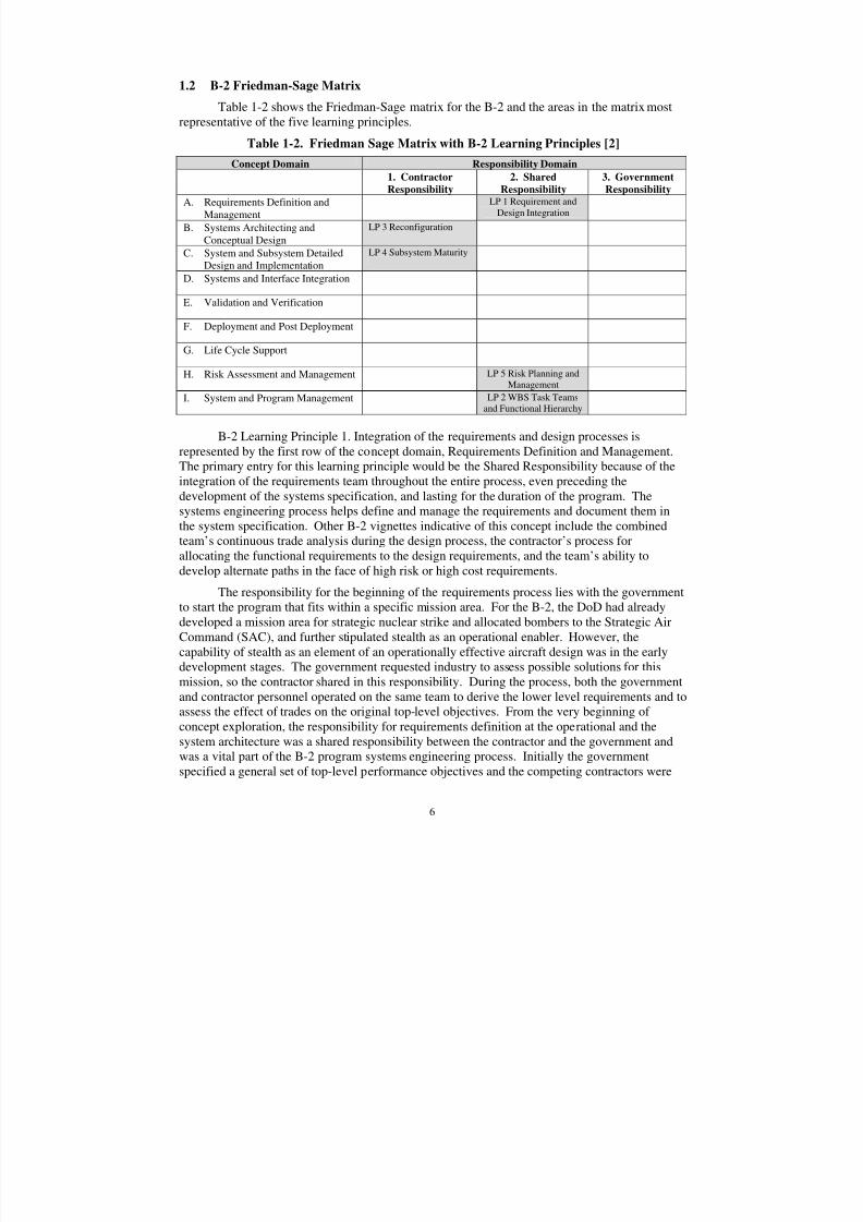
1.2 B-2 Friedman-Sage Matrix
Table 1-2 shows the Friedman-Sage matrix for the B-2 and the areas in the matrix mostrepresentative of the five learning principles.
Table 1-2. Friedman Sage Matrix with B-2 Learning Principles [2]
Concept Domain Responsibility Domain1. Contractor
Responsibility
2. Shared
Responsibility
3. Government
Responsibility
A. Requirements Definition andManagement
LP 1 Requirement andDesign Integration
B. Systems Architecting andConceptual Design
LP 3 Reconfiguration
C. System and Subsystem DetailedDesign and Implementation
LP 4 Subsystem Maturity
D. Systems and Interface Integration
E. Validation and Verification
F. Deployment and Post Deployment
G. Life Cycle Support
H. Risk Assessment and Management LP 5 Risk Planning andManagement
I. System and Program Management LP 2 WBS Task Teamsand Functional Hierarchy
B-2 Learning Principle 1. Integration of the requirements and design processes isrepresented by the first row of the concept domain, Requirements Definition and Management.The primary entry for this learning principle would be the Shared Responsibility because of theintegration of the requirements team throughout the entire process, even preceding the
development of the systems specification, and lasting for the duration of the program. Thesystems engineering process helps define and manage the requirements and document them inthe system specification. Other B-2 vignettes indicative of this concept include the combinedteam’s continuous trade analysis during the design process, the contractor’s process forallocating the functional requirements to the design requirements, and the team’s ability todevelop alternate paths in the face of high risk or high cost requirements.
The responsibility for the beginning of the requirements process lies with the governmentto start the program that fits within a specific mission area. For the B-2, the DoD had alreadydeveloped a mission area for strategic nuclear strike and allocated bombers to the Strategic AirCommand (SAC), and further stipulated stealth as an operational enabler. However, thecapability of stealth as an element of an operationally effective aircraft design was in the earlydevelopment stages. The government requested industry to assess possible solutions for thismission, so the contractor shared in this responsibility. During the process, both the governmentand contractor personnel operated on the same team to derive the lower level requirements and toassess the effect of trades on the original top-level objectives. From the very beginning of concept exploration, the responsibility for requirements definition at the operational and thesystem architecture was a shared responsibility between the contractor and the government andwas a vital part of the B-2 program systems engineering process. Initially the governmentspecified a general set of top-level performance objectives and the competing contractors were
8/3/2019 B-2 Systems Engineering Case Studies
http://slidepdf.com/reader/full/b-2-systems-engineering-case-studies 21/118
7
funded to pursue solutions and to further allocate the technical requirements in an ever-increasing level of detail and specificity. This process iterated continually during conceptexploration, and eventually converged to a contract specification.
B-2 Learning Principle 2. WBS Task Teams and Functional Hierarchy fall primarily atthe intersection of System and Program Management and Shared Responsibility. While it was
the government’s responsibility to organize the SPO and the contractor’s responsibility to selecttheir own organizational structure, all parties agreed to organize consistent with the WBS. Thethree major air vehicle company program organizations and the SPO team became part of theWBS Task Teams. In the case of the SPO and the prime contractor, Northrop, and the twoprimary subcontractors, Boeing and Vought, all were aligned functionally, employed projectmanagers, and constructed teams consisting of multi-discipline members.
B-2 Learning Principle 3. Air Vehicle Reconfiguration energized the team to conducttrade studies, integrate results, pursue alternatives suggested by members on the B-2 team,examine alternative design approaches recommended by interfacing technical disciplines andWBS Task Teams, and report the progress to the program technical and management decisionmaking bodies. This was organized, conducted, and implemented under the contractorresponsibility for the System Architecture and Conceptual Design.
B-2 Learning Principle 4. Subsystem Maturity was heavily influenced by the systemsengineering process and is again representative of a Contractor Responsibility within the Systemand Subsystem Detailed Design and Implementation (third row, first column). The contractorand sub-contractor team was responsible for the overall performance and schedule of subsystems. At least a part of the 18 month schedule slip in first flight (from the originalcontract date of 60 months after go-ahead) may have been avoidable had the reconfigurationimpact on subsystems immaturity not occurred.
B-2 Learning Principle 5. The Program employed Risk Closure plans that wereconstructed by the WBS Task Teams and included all the analyses, tests, demonstrations, and
other necessary design work. The work packages were planned into the budget and scheduletools. The entire task teams conducted these activities jointly, so this too, was a sharedresponsibility. The importance of a single, integrated, jointly developed, program wide risk management process, shared and understood by all, cannot be overemphasized.
The Friedman Sage matrix is used herein retrospectively, as an assessment tool for thesystems engineering process for the B-2 program. Its use in this case study does, however,highlight the effectiveness of the concept/matrix as an assessment tool. It should be clear to thestudent that the application of this tool to an ongoing program by the systems engineering staff and by the project/IPT/functional decision board would provide insight and guidance for action.This tool is highly effective in organizing an assessment of the ongoing effectiveness of the
systems engineering process because it covers all aspects of a program. Additionally, since itincludes responsibilities from both sides of the program (customer and supplier; industry andgovernment), it is an excellent communication catalyst to assure understanding by both parties.
8/3/2019 B-2 Systems Engineering Case Studies
http://slidepdf.com/reader/full/b-2-systems-engineering-case-studies 22/118
8
2.0 SYSTEM DESCRIPTION
The B-2 weapons system consists of the B-2 aircraft and onboard systems, supportequipment, training equipment, facilities, and personnel. It includes all hardware and software tomake it an operational system. The deployed B-2 weapons system consists of all of thesesystems working in an integrated manner. The systems engineering process is responsible for
the decomposition of requirements, allocation of the requirements to all levels of the design andto all elements, equipments, subsystems, hardware and software of all parts of the weaponsystems, and the verification that all requirements have been satisfied.
2.1 Mission
The B-2 Spirit is a multi-role bomber capable of delivering both conventional and nuclearmunitions. A revolutionary leap forward in technology, the bomber represents a fundamentalshift in the U.S. bomber modernization program. The B-2 brings significant and precisefirepower to bear, in a short time, anywhere on the globe, through previously impenetrabledefenses.
2.2 Features
The B-2 provides the penetrating flexibility and effectiveness inherent in mannedbombers. Low-observables, or “stealth,” characteristics give it the unique ability to penetrate anenemy’s most sophisticated defenses and threaten its most valued, and heavily defended, targets.The capability to penetrate air defenses at high altitude affords the platform efficient long rangecruise capability and holds even the most distant targets at risk, provides an effective retaliationcapability, an effective deterrent, and a formidable combat force. When coupled with the sisterbombers, the combined offensive capability is enormous. The B-52 provides significant payloadcapability and long-range missiles. The B-1 has a sophisticated Electronic Counter Measures(ECM) suite and largely low altitude penetration routes, further diluting the defenses forces.
The system’s low observability is derived from a combination of reduced infrared,
acoustic, electromagnetic, visual, and radar signatures. The low signature levels in these spectramake it difficult for sophisticated defensive systems to detect, track, and engage the B-2. Manyaspects of the low-observability process remain classified; however, the B-2’s compositematerials, special coatings, and flying-wing design all contribute to mission effectiveness.
The aircraft has a crew of two pilots, a pilot in the left seat and mission commander in theright, compared to the B-1B’s crew of four and the B-52’s crew of five.
2.3 System Design
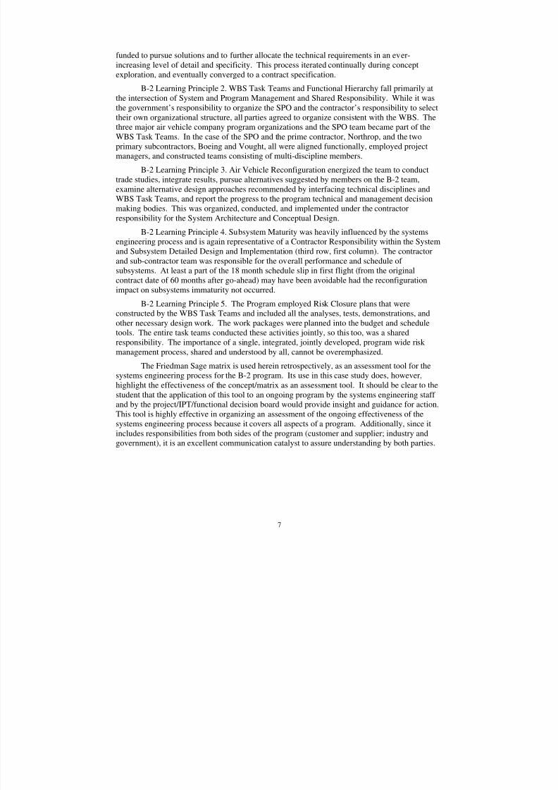
The B-2 configuration was developed by balancing aircraft performance and survivabilitybased on the mission scenarios laid out by the Strategic Airlift Command (SAC) in the late 1970sand refined in the early 1980s. Views of the aircraft shown in Figure 2-1 show the surfacedetails of the control surfaces, mating joints, access doors, and other interfaces. Of interest is theair data system, shown as sets of four small circles on the top view in front of the cockpit and onthe bottom view engine bay doors. This air data system has no standard pitot-static system;rather it senses small changes in pressure and flow as the angle of sideslip and attack change.Another unique feature, also used in the Northrop B-35 flying wing of the 1940s, is the split, orclamshell rudders near the tip of the outboard wing. These surfaces open on one side at a time inresponse to rudder inputs to control sideslip. They can also be opened simultaneously to providea speed brake function. They are augmented by asymmetric thrust of the engines to control
8/3/2019 B-2 Systems Engineering Case Studies
http://slidepdf.com/reader/full/b-2-systems-engineering-case-studies 23/118
9
sideslip during penetration mode1. The top view also shows the refueling receptacle aft of thecockpit in the center, about one third of the way back.
Figure 2-1. External View Drawings of the B-2 Aircraft [1]
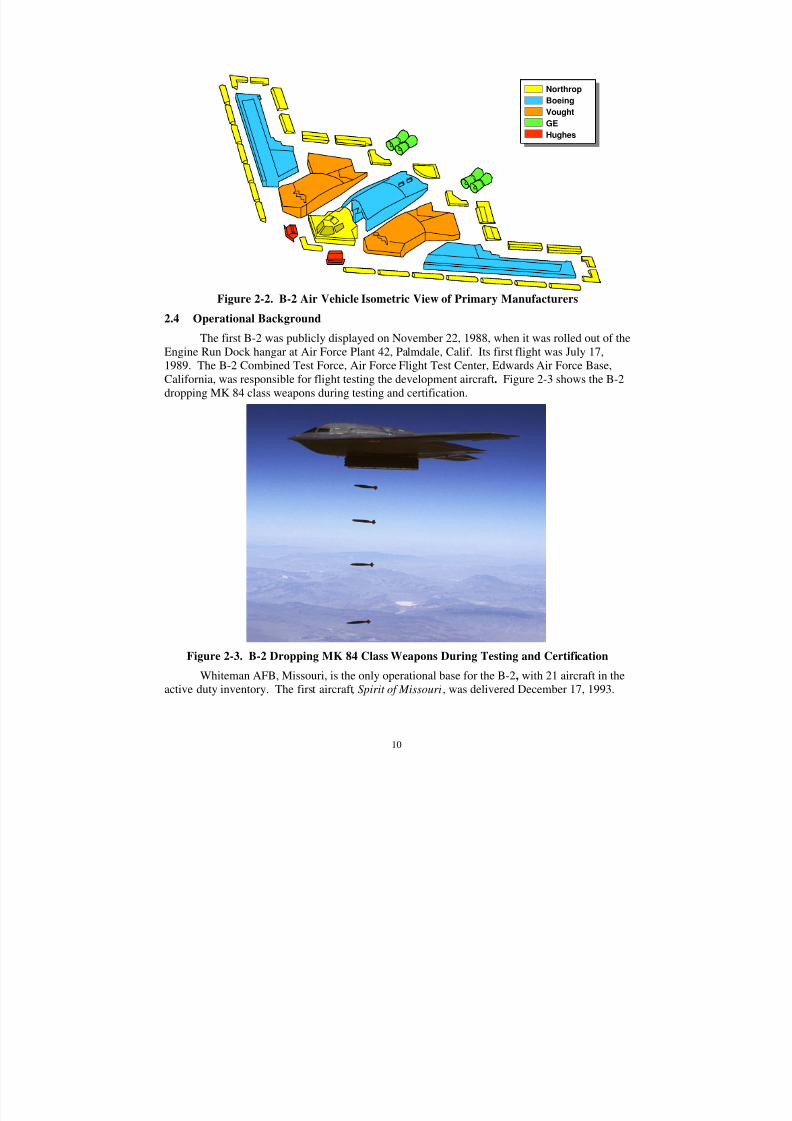
The company responsibilities for the design and manufacturing of the air vehicle areshown in Figure 2-2. This was decided early in the program, prior to the company proposal.The prime contractor, responsible for overall system design and integration, was NorthropCorporation. Boeing Military Airplanes Co., Hughes Radar Systems Group, General Electric
Aircraft Engine Group and Vought Aircraft Industries, Inc. were key members of the aircraftcontractor team.
1 Also noted in the front view are four auxiliary intake doors protruding above the inlets. These doors, nowdeactivated, provided additional engine air flow during low speed conditions to reduce the take-off distance.
8/3/2019 B-2 Systems Engineering Case Studies
http://slidepdf.com/reader/full/b-2-systems-engineering-case-studies 24/118
8/3/2019 B-2 Systems Engineering Case Studies
http://slidepdf.com/reader/full/b-2-systems-engineering-case-studies 25/118
11
Depot maintenance for the B-2 is performed at the Oklahoma City Air Logistics Center at TinkerAFB, OK
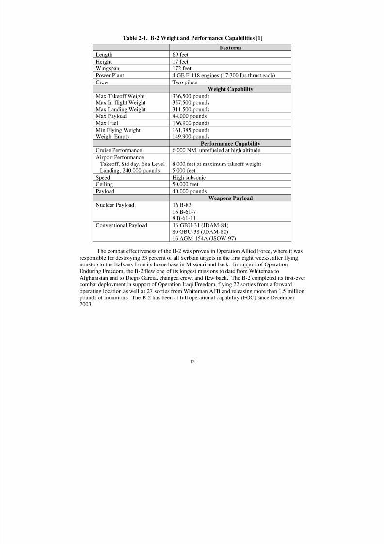
Figure 2-4 shows the B-2 in a turn at altitude. Careful examination of the photographshows the split rudders are deflected, denoting the air vehicle is outside the maneuver limits forthe low observable penetration mode. When the aircraft is in penetration mode, the maneuvers
are restricted to allow control of sideslip with differential thrust of the engines. When therudders split to control sideslip, it causes an increase in radar cross section.
Figure 2-4. B-2 in a turn at altitude [1]
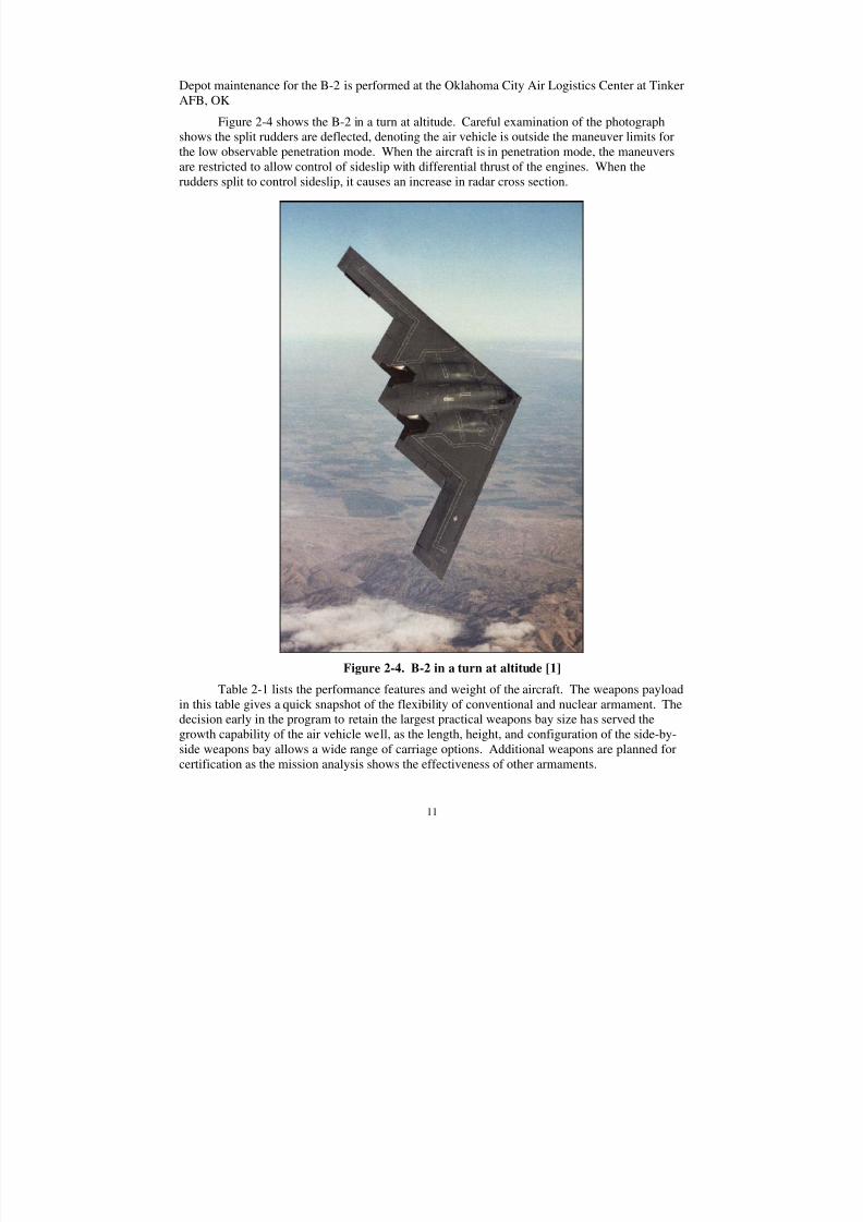
Table 2-1 lists the performance features and weight of the aircraft. The weapons payloadin this table gives a quick snapshot of the flexibility of conventional and nuclear armament. Thedecision early in the program to retain the largest practical weapons bay size has served thegrowth capability of the air vehicle well, as the length, height, and configuration of the side-by-side weapons bay allows a wide range of carriage options. Additional weapons are planned forcertification as the mission analysis shows the effectiveness of other armaments.
8/3/2019 B-2 Systems Engineering Case Studies
http://slidepdf.com/reader/full/b-2-systems-engineering-case-studies 26/118
12
Table 2-1. B-2 Weight and Performance Capabilities [1]
Features
Length 69 feet
Height 17 feet
Wingspan 172 feet
Power Plant 4 GE F-118 engines (17,300 lbs thrust each)Crew Two pilots
Weight Capability
Max Takeoff WeightMax In-flight WeightMax Landing Weight
336,500 pounds357,500 pounds311,500 pounds
Max Payload 44,000 pounds
Max Fuel 166,900 pounds
Min Flying WeightWeight Empty
161,385 pounds149,900 pounds
Performance Capability
Cruise Performance 6,000 NM, unrefueled at high altitude
Airport PerformanceTakeoff, Std day, Sea LevelLanding, 240,000 pounds
8,000 feet at maximum takeoff weight5,000 feet
Speed High subsonic
Ceiling 50,000 feet
Payload 40,000 pounds
Weapons Payload
Nuclear Payload 16 B-8316 B-61-7
8 B-61-11Conventional Payload 16 GBU-31 (JDAM-84)80 GBU-38 (JDAM-82)16 AGM-154A (JSOW-97)
The combat effectiveness of the B-2 was proven in Operation Allied Force, where it wasresponsible for destroying 33 percent of all Serbian targets in the first eight weeks, after flyingnonstop to the Balkans from its home base in Missouri and back. In support of OperationEnduring Freedom, the B-2 flew one of its longest missions to date from Whiteman toAfghanistan and to Diego Garcia, changed crew, and flew back. The B-2 completed its first-evercombat deployment in support of Operation Iraqi Freedom, flying 22 sorties from a forwardoperating location as well as 27 sorties from Whiteman AFB and releasing more than 1.5 millionpounds of munitions. The B-2 has been at full operational capability (FOC) since December2003.
8/3/2019 B-2 Systems Engineering Case Studies
http://slidepdf.com/reader/full/b-2-systems-engineering-case-studies 27/118
13
3.0 B-2 PROGRAM EXECUTION
This section will follow the execution of the B-2 program from the inception of an idea in1978 to the first flight on July 17, 1989. The discussion will introduce the transition toproduction and operational activation, but the concentration of the case is on the application of the systems engineering process from the early days to the first flight.
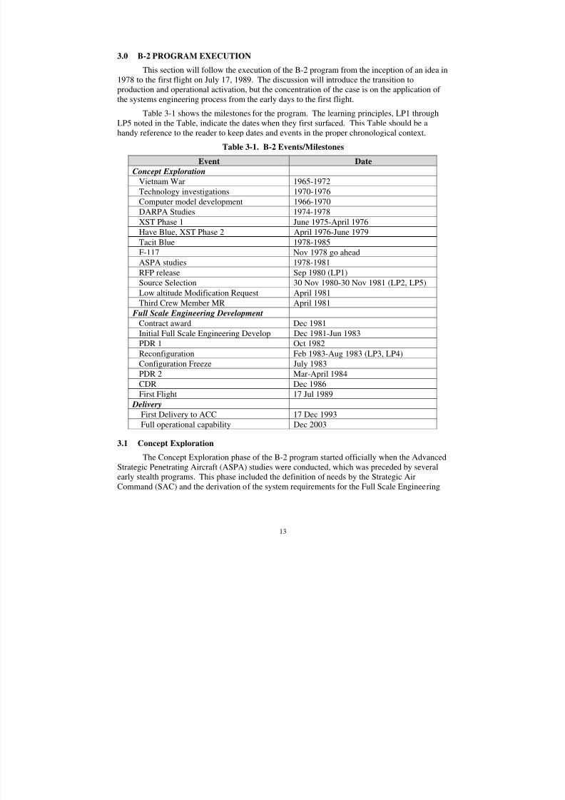
Table 3-1 shows the milestones for the program. The learning principles, LP1 throughLP5 noted in the Table, indicate the dates when they first surfaced. This Table should be ahandy reference to the reader to keep dates and events in the proper chronological context.
Table 3-1. B-2 Events/Milestones
Event Date
Concept Exploration
Vietnam War 1965-1972
Technology investigations 1970-1976
Computer model development 1966-1970
DARPA Studies 1974-1978XST Phase 1 June 1975-April 1976
Have Blue, XST Phase 2 April 1976-June 1979
Tacit Blue 1978-1985
F-117 Nov 1978 go ahead
ASPA studies 1978-1981
RFP release Sep 1980 (LP1)
Source Selection 30 Nov 1980-30 Nov 1981 (LP2, LP5)
Low altitude Modification Request April 1981
Third Crew Member MR April 1981
Full Scale Engineering Development
Contract award Dec 1981Initial Full Scale Engineering Develop Dec 1981-Jun 1983
PDR 1 Oct 1982
Reconfiguration Feb 1983-Aug 1983 (LP3, LP4)
Configuration Freeze July 1983
PDR 2 Mar-April 1984
CDR Dec 1986
First Flight 17 Jul 1989
Delivery
First Delivery to ACC 17 Dec 1993
Full operational capability Dec 2003
3.1 Concept Exploration
The Concept Exploration phase of the B-2 program started officially when the AdvancedStrategic Penetrating Aircraft (ASPA) studies were conducted, which was preceded by severalearly stealth programs. This phase included the definition of needs by the Strategic AirCommand (SAC) and the derivation of the system requirements for the Full Scale Engineering
8/3/2019 B-2 Systems Engineering Case Studies
http://slidepdf.com/reader/full/b-2-systems-engineering-case-studies 28/118
14
Development contract. It also balanced the desires of the user between technology risk andcapability.
3.1.1 Early Stealth Programs
The concept of stealth technology intrigued aircraft designers from the beginning of theinvention of radar. Engineers and scientists investigated various techniques to avoid detectiondating to the 1940s. Designs to reduce noise even preceded these efforts. By the mid-1960s, theAir Force Avionics Laboratory at Wright Patterson Air Force Base, Ohio had funded studies todevelop radar cross-section prediction computer programs, camouflage techniques, models,materials and concepts [5]. Studies of radar absorbing materials (RAM) and shaping techniqueswere also funded and had yielded a concept called “iron paint”, a technique to embed ferriteparticles in a quarter inch thick flexible rubberized film. In the early 1970s, research hadcontinued into methodologies to control the physical scattering of sensor outputs forrepresentative aircraft shapes. Northrop had successfully developed a radar cross-section (RCS)prediction code called GEMSCAT and had successfully predicted the radar cross-section of theF-4. Teledyne Ryan had experimented and flown low radar cross-section drones and haddeveloped analytical techniques for the design of leading-edge RAM.
The early work by both the government and industry during this timeframe resulted inproving low observables could successfully be applied to aircraft, ships, and other vehicles. Thecurrent inventory of stealth platforms throughout the military can all trace their roots to theseearly technology maturation programs and the initial prototype aircraft developed throughout the1970s.
The experience in Vietnam showed Air Force planners the emerging trend of theexpanding threat from radar detection and radar guided missiles. This trend was forcing achange in tactics to assure aircraft survivability. F-4 Wild Weasels were used to encourage theradars to try to illuminate them so the Weasel crews could try to destroy the radars. The constantthreat of the more sophisticated and extremely capable radar/missile complexes became a
priority in mission planning. However, it was the Yom Kipper War in Oct 1973 that providedthe catalyst needed to bring the emerging stealth technology into the forefront of interest and tofinally provide the impetus that would result in their emergence as operational systems. Thevulnerability of U.S. aircraft to the new and expanding Soviet air-to-air and surface-to-airmissiles and their companion radar was a disturbing fact of life. Many of the frontline Israelifighter aircraft shot down in the Yom Kipper War were the frontline aircraft of their Allies.They were falling victim to the front line Soviet radars at an alarming rate. In 1974, the DefenseAdvanced Research Projects Agency (DARPA) initiated studies to determine radar cross-sectionlevels required to defeat the Soviet threats and various ways these levels may be achieved.Northrop and McDonnell Douglas received contracts for this work. Lockheed was soon added tothe list.
2DARPA initiated the Experimental Survivability Testbed (XST) program in the
summer of 1975 to conduct aircraft systems analysis on low RCS vehicles and to conduct radarcross-section testing of representative configurations and components. Northrop and Lockheedboth received a Phase 1 contract to test models of their concepts mounted on a pole at the
2An excellent summary of the early works in low observables, along with the details of Have Blue and the
F-117A can be found in Reference 4.
8/3/2019 B-2 Systems Engineering Case Studies
http://slidepdf.com/reader/full/b-2-systems-engineering-case-studies 29/118
15
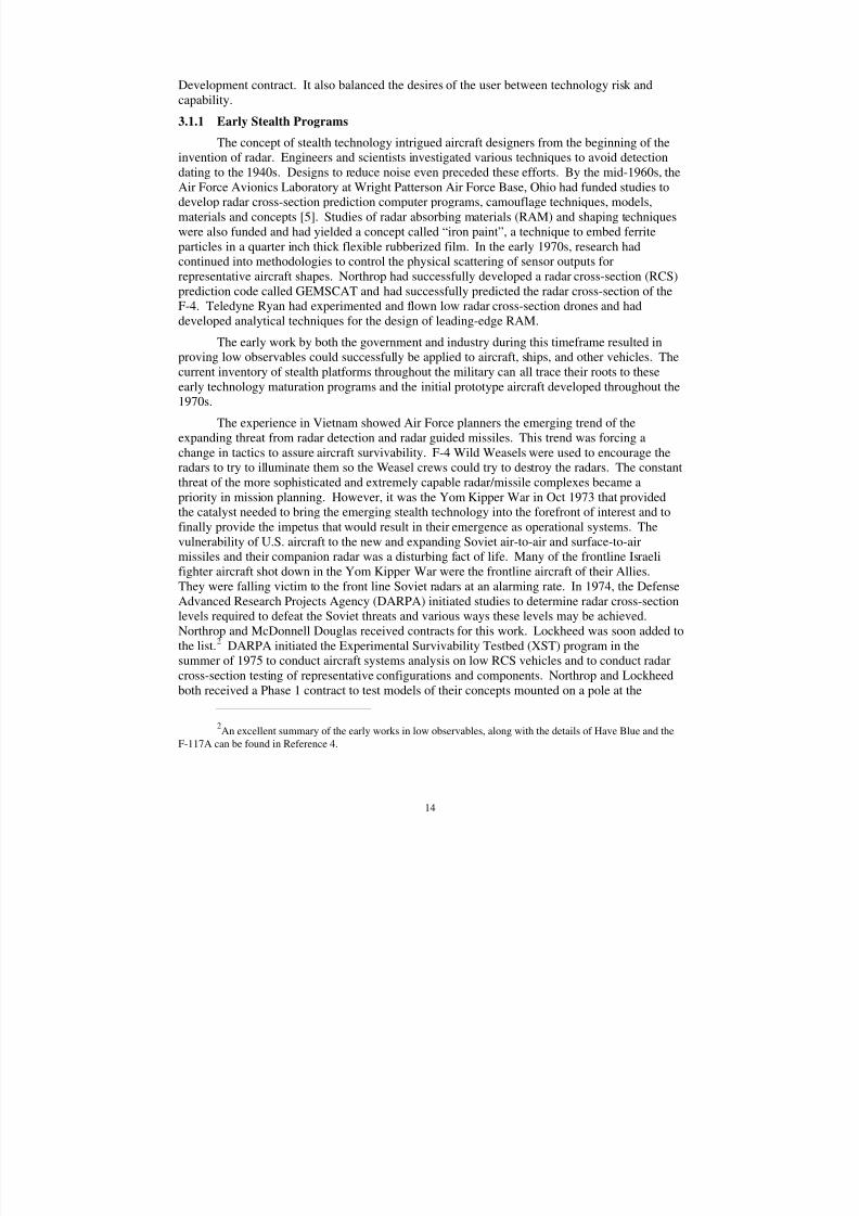
government RCS test range at White Sands Missile Range, NM. Lockheed was selected as thewinner for Phase 2 in a close competition in April 1976 and flew the first Have Blue aircraftDecember 1, 1977
3. Figure 3-1 shows both the Lockheed and the Northrop XST proposal
configurations.
Figure 3-1. Lockheed Have Blue (left) and Northrop (right) XST Aircraft [5].
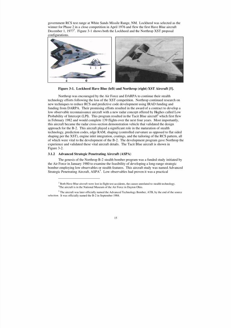
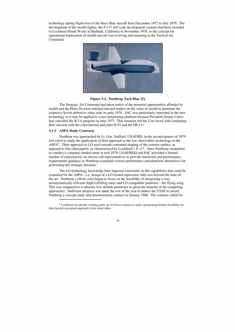
Northrop was encouraged by the Air Force and DARPA to continue their stealthtechnology efforts following the loss of the XST competition. Northrop continued research onnew techniques to reduce RCS and predictive code development using IRAD funding andfunding from DARPA. Their promising efforts resulted in the award of a contract to develop alow observable reconnaissance aircraft with a new radar concept offered by Hughes called LowProbability of Intercept (LPI). This program resulted in the Tacit Blue aircraft4 which first flewin February 1982 and would complete 139 flights over the next four years. Most importantly,this aircraft became the radar cross-section demonstration vehicle that validated the designapproach for the B-2. This aircraft played a significant role in the maturation of stealth
technology, prediction codes, edge RAM, shaping (controlled curvature as opposed to flat sidedshaping per the XST), engine inlet integration, coatings, and the tailoring of the RCS pattern, allof which were vital to the development of the B-2. The development program gave Northrop theexperience and validated these vital aircraft details. The Tacit Blue aircraft is shown inFigure 3-2.
3.1.2 Advanced Strategic Penetrating Aircraft (ASPA)
The genesis of the Northrop B-2 stealth bomber program was a funded study initiated bythe Air Force in January 1980 to examine the feasibility of developing a long-range strategicbomber employing low observables or stealth features. This aircraft study was named AdvancedStrategic Penetrating Aircraft, ASPA5. Low observables had proven it was a practical
3 Both Have Blue aircraft were lost in flight test accidents, the causes unrelated to stealth technology.4The aircraft is in the National Museum of the Air Force in Dayton Ohio.
5 The aircraft was later officially named the Advanced Technology Bomber, ATB, by the end of the sourceselection. It was officially named the B-2 in September 1984.
8/3/2019 B-2 Systems Engineering Case Studies
http://slidepdf.com/reader/full/b-2-systems-engineering-case-studies 30/118
16
technology during flight-tests of the Have Blue aircraft from December 1977 to July 1979. Thedevelopment of the stealth fighter, the F-117 full scale development contract had been awardedto Lockheed Skunk Works in Burbank, California in November 1978, so the concept foroperational deployment of stealth aircraft was evolving and maturing in the Tactical AirCommand.
Figure 3-2. Northrop Tacit Blue [5].
The Strategic Air Command had taken notice of the potential opportunities afforded bystealth and the Plans Division initiated internal studies on the value of stealth to penetrate theextensive Soviet defensive radar suite in early 1978. SAC was particularly interested in the newtechnology as it may be applied to a new penetrating platform because President Jimmy Carterhad cancelled the B-1A program in June 1977. This situation left the User faced with continuingtheir mission with the conventional and older B-52 and the FB-111.
3.1.3 ASPA Study Contracts
Northrop was approached by Lt. Gen. Stafford, USAF/RD, in the second quarter of 1979and ask ed to study the application of their approach to the low observables technology to theASPA
6. Their approach to LO used smooth contoured shaping of the exterior surface, as
opposed to flat-sided panels, as characterized by Lockheed’s F-117. Once Northrop committedto conduct a company-funded study in mid 1979, USAF/RDQ and SAC provided a limitednumber of experienced, on-site/on-call representatives to provide functional and performancerequirements guidance as Northrop examined various performance and planform alternatives forperforming the strategic missions.
The LO technology knowledge base imposed constraints on the capabilities that could beexamined for the ASPA – i.e. design of a LO treated supersonic inlet was beyond the state-of-
the-art. Northrop’s efforts soon began to focus on the feasibility of integrating a veryaerodynamically efficient (high Lift/Drag ratio) and LO compatible planform – the flying wing.This was compared to a subsonic low altitude penetrator to glean the benefits of the competingapproaches. Sufficient progress was made the rest of the year to induce the USAF to awardNorthrop a concept study and demonstration contract in January 1980. The contract called for
6 Lockheed was already working under an Air Force contract to study a penetrating bomber feasibility fortheir faceted conceptual approach to low observables
8/3/2019 B-2 Systems Engineering Case Studies
http://slidepdf.com/reader/full/b-2-systems-engineering-case-studies 31/118
17
wind tunnel model tests of the aerodynamic configuration and large-scale RCS model tests of thesame external mold lines, in addition to continuing the development of the aircraft and weaponsystem conceptual designs.
Once Northrop had agreed to study the ASPA in the late spring of 1979, the SystemsAnalysis group within Northrop Advanced Projects formulated a matrix of analyses, each
addressing a feature of the long range penetration bomber effectiveness. The independentvariables were engineering parameters of systems and, in some cases, subsystem design. Thisanalysis technique had generally been known as “Measures of Effectiveness” (MOE). AdvancedProjects had started constructing MOE analysis models as early as 1976 during Northrop’sparticipation in the XST program and continued refining and expanding its models during theconceptual and preliminary design phases of Tacit Blue. Central to this capability was a verysimple generic, all-aspect, multi-frequency RCS description that was empirically based on theknowledge accumulated by AP’s RCS engineers from the thousands of experimental tests on theradar range. This model construct was so flexible that it could be used to help the designers tosynthesize aircraft configuration. All prior RCS models were far to complex and were onlyuseful for analysis of already created configurations.
The ASPA studied the same objectives of all intercontinental strategic bombers, namely6,000 nm range unrefueled and 10,000 pounds of payload. The attractiveness of stealth toenhance survivability gave the edge to the ASPA platforms over then conventional approaches,although all previous approaches were considered, including ECM. By appreciating that a widevariety of aircraft and configurations can be made to fly adequately with sufficient thrust and fly-by-wire stability augmentation, an aircraft’s wings-level best case range payload features can beestimated with just a two dimensional planform representation.
The MOE addressed as dependent variables a number of mission parameters such asrange, penetration altitude, and, most importantly, the elements of what constitutes survivability,such as detection range, time-in-track, firing opportunity time, etc. Without a preconceived
notion of what the weapon system would physically look like, engineering parameters, such asleading/trailing sweep, inlet/exhaust location, etc., were traded off as independent variables.Features of the three basic aircraft types, wing-body-tail, flying wing, and blended-wing-body(delta) were studied because the MOE analysis was made as deterministic and transparent aspossible, widespread confidence in the engineering tradeoffs was easily achieved. In less thantwo months of study addressing worst case air defense scenarios projected 20 years to the future,the most effective RCS features became obvious. Significantly, the analysis showed it waspossible to configure the bomber for survivable penetration (of air defenses) at high altitude. Aless stressing low altitude penetration would be even more survivable, albeit with a less efficientaircraft [3, Griskey].
The effort during this period was focused on system engineering studies of the weapon
system, air vehicle, avionics, and armament systems; conceptual design and trade studies of theairframe structure and subsystems concepts; development testing of large and small scale LO andaerodynamic models and representative structures; and the conceptual construct of manufacturing and logistics support plans. The presence of the SAC and RDQ representativesgreatly facilitated these efforts, because Northrop did not have a large knowledge base of SACoperations and the SIOP missions.
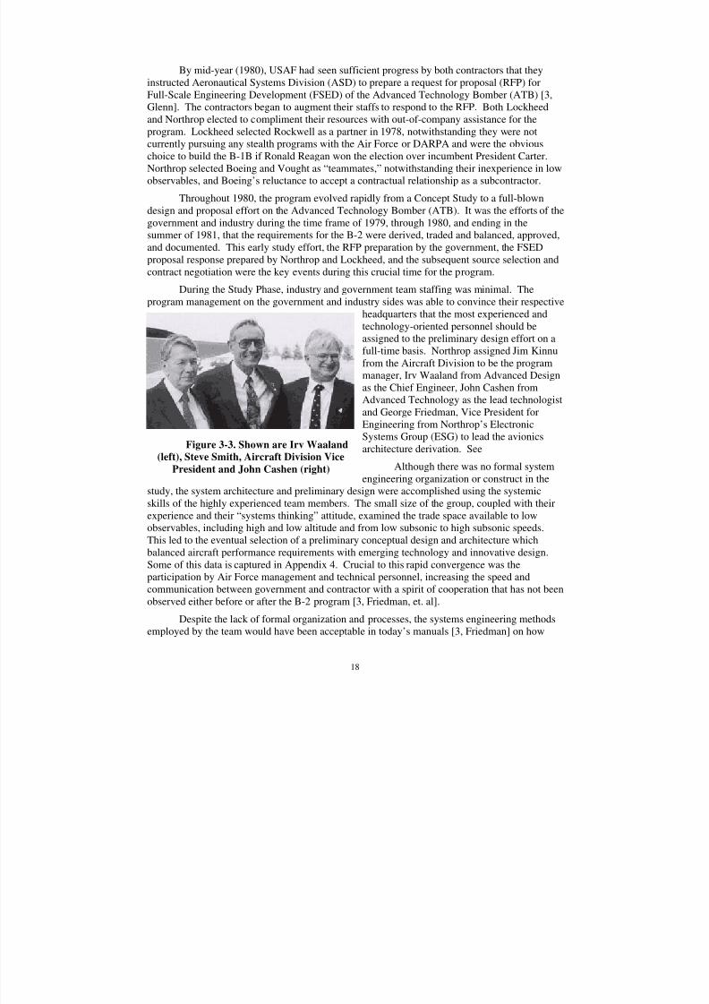
8/3/2019 B-2 Systems Engineering Case Studies
http://slidepdf.com/reader/full/b-2-systems-engineering-case-studies 32/118
18
By mid-year (1980), USAF had seen sufficient progress by both contractors that theyinstructed Aeronautical Systems Division (ASD) to prepare a request for proposal (RFP) forFull-Scale Engineering Development (FSED) of the Advanced Technology Bomber (ATB) [3,Glenn]. The contractors began to augment their staffs to respond to the RFP. Both Lockheedand Northrop elected to compliment their resources with out-of-company assistance for the
program. Lockheed selected Rockwell as a partner in 1978, notwithstanding they were notcurrently pursuing any stealth programs with the Air Force or DARPA and were the obviouschoice to build the B-1B if Ronald Reagan won the election over incumbent President Carter.Northrop selected Boeing and Vought as “teammates,” notwithstanding their inexperience in lowobservables, and Boeing’s reluctance to accept a contractual relationship as a subcontractor.
Throughout 1980, the program evolved rapidly from a Concept Study to a full-blowndesign and proposal effort on the Advanced Technology Bomber (ATB). It was the efforts of thegovernment and industry during the time frame of 1979, through 1980, and ending in thesummer of 1981, that the requirements for the B-2 were derived, traded and balanced, approved,and documented. This early study effort, the RFP preparation by the government, the FSEDproposal response prepared by Northrop and Lockheed, and the subsequent source selection and
contract negotiation were the key events during this crucial time for the program.
During the Study Phase, industry and government team staffing was minimal. Theprogram management on the government and industry sides was able to convince their respective
headquarters that the most experienced andtechnology-oriented personnel should beassigned to the preliminary design effort on afull-time basis. Northrop assigned Jim Kinnufrom the Aircraft Division to be the programmanager, Irv Waaland from Advanced Designas the Chief Engineer, John Cashen fromAdvanced Technology as the lead technologistand George Friedman, Vice President forEngineering from Northrop’s ElectronicSystems Group (ESG) to lead the avionicsarchitecture derivation. See
Although there was no formal systemengineering organization or construct in the
study, the system architecture and preliminary design were accomplished using the systemicskills of the highly experienced team members. The small size of the group, coupled with theirexperience and their “systems thinking” attitude, examined the trade space available to lowobservables, including high and low altitude and from low subsonic to high subsonic speeds.
This led to the eventual selection of a preliminary conceptual design and architecture whichbalanced aircraft performance requirements with emerging technology and innovative design.Some of this data is captured in Appendix 4. Crucial to this rapid convergence was theparticipation by Air Force management and technical personnel, increasing the speed andcommunication between government and contractor with a spirit of cooperation that has not beenobserved either before or after the B-2 program [3, Friedman, et. al].
Despite the lack of formal organization and processes, the systems engineering methodsemployed by the team would have been acceptable in today’s manuals [3, Friedman] on how
Figure 3-3. Shown are Irv Waaland
(left), Steve Smith, Aircraft Division Vice
President and John Cashen (right)
8/3/2019 B-2 Systems Engineering Case Studies
http://slidepdf.com/reader/full/b-2-systems-engineering-case-studies 33/118
19
systems engineering should be conducted in the early phases: focus on mission requirements andcampaign models – augmented by many in-depth discussions with operational personnel,functional flow diagrams, requirements flow down and trade studies. Communications wereaccomplished by a “sea of thousands of viewgraphs”, with the decisions of each meetingcompactly captured by a page or two of memos, signed by the stakeholders of that part of design.
Several rooms with sheet metal walls were devoted to the building of the many presentationsalways in process, with a complex “configuration management” control on the status of approvalof each slide.
It was during the study phase that the fundamental architecture of the B-2 avionicssystem was derived. The major architectural decisions were in the areas of the radar, navigation,crew station, computer, software, and data bus. Three primary objectives were established forthe design trades: in order of priority [3, Wheelock]:
1. Survivability
2. Effectiveness
3. Range/payload and Lift/ Drag (L/D)
Survivability’s components included reaction time, takeoff distance, observables, systemhardness, altitude, speed and active defense. Effectiveness’s components included range,navigational accuracy, target acquisition, bomb damage assessment, reliability, payload, weaponaccuracy, and speed. Weight has long been, and continues to be, a driving system requirement.It is useful as a cost estimation relationship, but also drove the B-2 high altitude capability andrange.
The navigation subsystem trade off for reliability indicated the need for redundantnavigation subsystems. Other long-range bombers had two inertial navigators initialized by aperiod of gyro compassing and radar fixes during climb out, requiring updates by additionalradar fixes at intervals along the route. Reaction time was a critical issue regarding initial air
strikes against our bases; thus the bomber needed a navigation system that could be operationalwithin the timeline of other startup functions. Also survivability concerns dictated minimumemissions for navigational updates, especially at high altitudes above enemy airspace. Othernavigational considerations included the need to deliver gravity weapons with high precisionafter long periods over water where updates were not available. The derived architectureidentified an astrotracker with dual inertial platforms along with Low Probability of Intercept(LPI) radar updates
7.
Radar subsystem decisions were also made early on that had far reaching implications.Although the primary mission was strategic nuclear strike, careful consideration was given to thelikelihood of tactical, conventional weapon delivery. Tradeoffs were made, especially in the areaof the radar resolution, where studies were made regarding the benefits of higher resolution:higher navigational accuracy, superior ability to acquire a wide range of target classes and toperform bomb damage assessment, pattern recognition and the ability to deliver weapons moreaccurately in a “relative guidance system” manner.
7 While the system currently has GPS, it was not initially available but full provisions were incorporated aspart of the FSED contract.
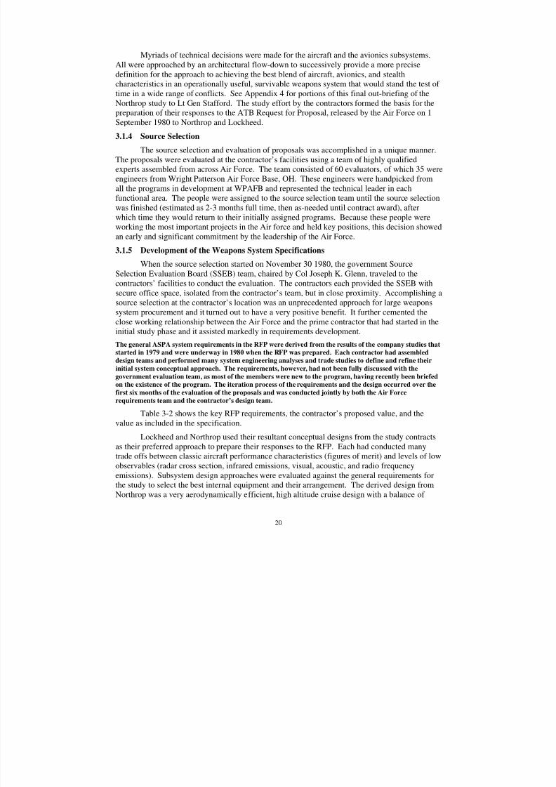
8/3/2019 B-2 Systems Engineering Case Studies
http://slidepdf.com/reader/full/b-2-systems-engineering-case-studies 34/118
20
Myriads of technical decisions were made for the aircraft and the avionics subsystems.All were approached by an architectural flow-down to successively provide a more precisedefinition for the approach to achieving the best blend of aircraft, avionics, and stealthcharacteristics in an operationally useful, survivable weapons system that would stand the test of time in a wide range of conflicts. See Appendix 4 for portions of this final out-briefing of the
Northrop study to Lt Gen Stafford. The study effort by the contractors formed the basis for thepreparation of their responses to the ATB Request for Proposal, released by the Air Force on 1September 1980 to Northrop and Lockheed.
3.1.4 Source Selection
The source selection and evaluation of proposals was accomplished in a unique manner.The proposals were evaluated at the contractor’s facilities using a team of highly qualifiedexperts assembled from across Air Force. The team consisted of 60 evaluators, of which 35 wereengineers from Wright Patterson Air Force Base, OH. These engineers were handpicked fromall the programs in development at WPAFB and represented the technical leader in eachfunctional area. The people were assigned to the source selection team until the source selectionwas finished (estimated as 2-3 months full time, then as-needed until contract award), afterwhich time they would return to their initially assigned programs. Because these people wereworking the most important projects in the Air force and held key positions, this decision showedan early and significant commitment by the leadership of the Air Force.
3.1.5 Development of the Weapons System Specifications
When the source selection started on November 30 1980, the government SourceSelection Evaluation Board (SSEB) team, chaired by Col Joseph K. Glenn, traveled to thecontractors’ facilities to conduct the evaluation. The contractors each provided the SSEB withsecure office space, isolated from the contractor’s team, but in close proximity. Accomplishing asource selection at the contractor’s location was an unprecedented approach for large weaponssystem procurement and it turned out to have a very positive benefit. It further cemented the
close working relationship between the Air Force and the prime contractor that had started in theinitial study phase and it assisted markedly in requirements development.
The general ASPA system requirements in the RFP were derived from the results of the company studies that
started in 1979 and were underway in 1980 when the RFP was prepared. Each contractor had assembled
design teams and performed many system engineering analyses and trade studies to define and refine their
initial system conceptual approach. The requirements, however, had not been fully discussed with the
government evaluation team, as most of the members were new to the program, having recently been briefed
on the existence of the program. The iteration process of the requirements and the design occurred over the
first six months of the evaluation of the proposals and was conducted jointly by both the Air Force
requirements team and the contractor’s design team.
Table 3-2 shows the key RFP requirements, the contractor’s proposed value, and the
value as included in the specification.Lockheed and Northrop used their resultant conceptual designs from the study contracts
as their preferred approach to prepare their responses to the RFP. Each had conducted manytrade offs between classic aircraft performance characteristics (figures of merit) and levels of lowobservables (radar cross section, infrared emissions, visual, acoustic, and radio frequencyemissions). Subsystem design approaches were evaluated against the general requirements forthe study to select the best internal equipment and their arrangement. The derived design fromNorthrop was a very aerodynamically efficient, high altitude cruise design with a balance of
8/3/2019 B-2 Systems Engineering Case Studies
http://slidepdf.com/reader/full/b-2-systems-engineering-case-studies 35/118
21
good aircraft performance and low observables levels. The primary role of the ASPA was forlong range, high altitude cruise penetration of the Soviet radar network. There were 14 missionsstipulated in an appendix for calculation of range, payload, PSR, structural durability designspectrums, and anything requiring an operational mission for events, weapons, environments,and penetration corridors. The proposed system concept was designed for HI-HI-HI-HI
missions, such as the one in Figure 3-4, which is duplicated from the original 1980 study. It isshown here for illustration of a typical HI-HI-HI-HI mission.
Table 3-2. RFP and Specification Requirements
Document RFP Proposal Specification
Range nautical miles 6,000 8,500 6,000
Payload lbs 40,000 40,000 40,000
Low altitudealt above terrainMach
ResidualCapacity
400’ w/o TF0.6M
200’ w/ TF0.7M
High altitudeCruise altitude
Cruise Mach
>35,000 ft
>0.8M
>50,000 ft
>0.8M
50,000 ft max
>0.8MPSR 0.90 0.90 0.90
Wing span -- 172 ft --
Gross weight -- 269,000 lbs --LegendTF = Terrain FollowingPSR = Primary System Reliability
There was also a mission for HI-LO-LO-HI operation stipulated in the original RFP, butthis was a fallout capability, not a specific design point. See Figure 3-5, again duplicated fromthe original 1980 study, and shown with the low altitude concept as illustrative of a HI-HI-LO-
LO mission. The low altitude mission in the original RFP did not stipulate the maximum speedor terrain following altitude capability. It should be noted that because this was neither aspecified design point nor a primary mission, the contractors’ high-altitude design would nothave added additional functionality to address a low altitude/ high speed operation.
A large scale radar cross-section (RCS) pole model of each contractor’s conceptualdesign was initially built and tested at the RASCAT facility, White Sands, NM as part of theStudy Contracts. Both contractors modified their models and retested them during theevaluation. The data formed the basis of the RCS trade studies, the preliminary RCSspecification, and the survivability assessment by the SSEB during the evaluation period.
Each contractor had prepared specifications, a Work Breakdown Structure (WBS), the
contract Statement of Work (SOW), and model contract as part of their proposal submittal.When developing the specifications, each contractor documented its design approach in a verydescriptive Part II specification format. These specifications, however, were far moredescriptive than desired by the Air Force. The government desired only a performance-basedPart I type specification for the contract, with the eventual Part II specifications to be developedduring the conduct of the program by the selected contractor.
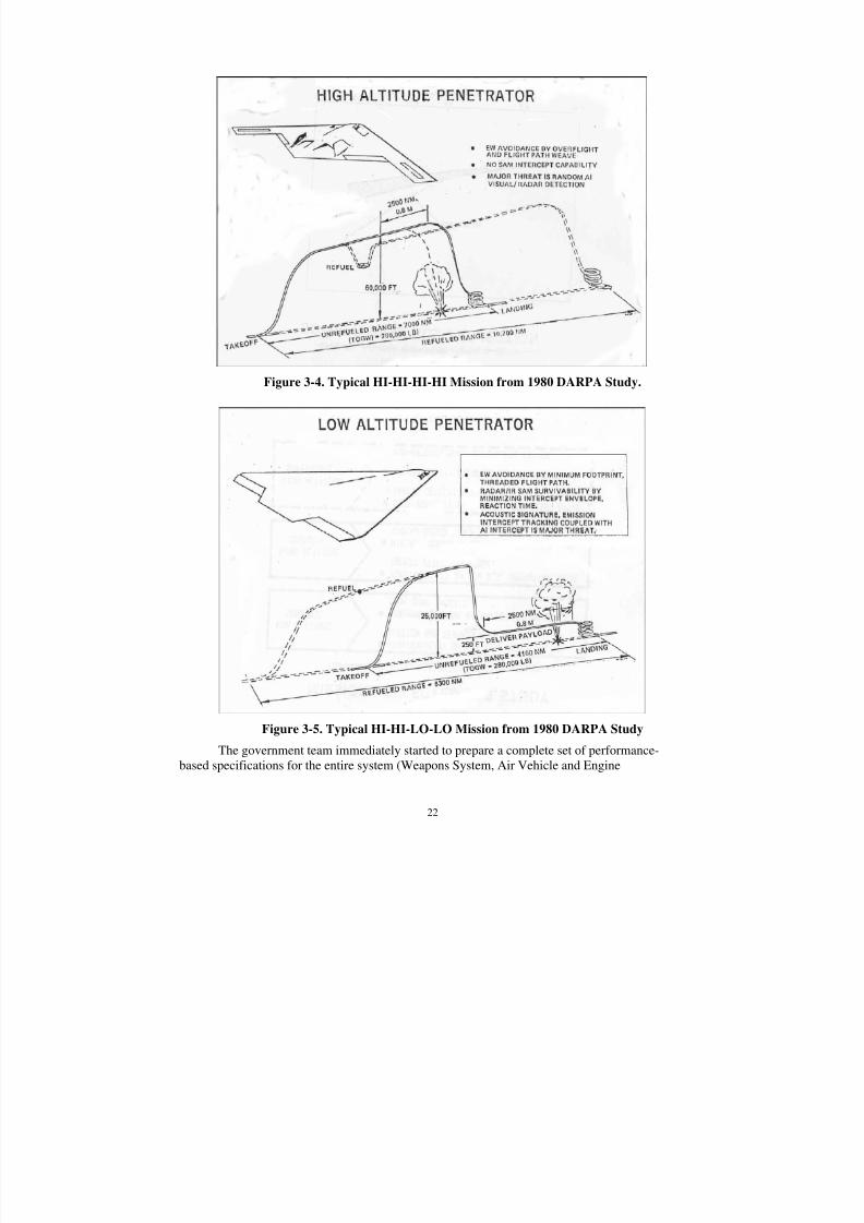
8/3/2019 B-2 Systems Engineering Case Studies
http://slidepdf.com/reader/full/b-2-systems-engineering-case-studies 36/118
22
Figure 3-4. Typical HI-HI-HI-HI Mission from 1980 DARPA Study.
Figure 3-5. Typical HI-HI-LO-LO Mission from 1980 DARPA Study
The government team immediately started to prepare a complete set of performance-based specifications for the entire system (Weapons System, Air Vehicle and Engine

8/3/2019 B-2 Systems Engineering Case Studies
http://slidepdf.com/reader/full/b-2-systems-engineering-case-studies 37/118
23
specifications). Concurrently, they were conducting the evaluation of the proposals. Since eachof the members of SSEB was handpicked for their expertise and was well experienced in thedevelopment of specifications, they were all given the latitude to leave the governmentevaluation area and speak directly with the contractor’s engineer in their technical discipline.This dialog created an understanding by the evaluator of the implication of their proposed
performance requirements on the difficulty to design and integrate its subsystem. It also gave thedesigner a detailed understanding of the objective of the requirements. This communicationgenerated an outstanding understanding by both parties of the implications of each requirementand the difficulty of the design to achieve them.
If an evaluator did not understand why the contractor engineer had chosen a particularpath, or the evaluator thought there might be a better approach, the evaluator was allowed to talk directly to the contractor engineer at their desk. They would discuss the mission, the designapproach for the technical discipline, and develop an understanding of what they both thoughtwas best for the overall system. Following the dialog, the government evaluator would constructproposed specification language and present the proposed requirements wording to thespecification board for incorporation into the government performance-based specifications. If
the proposed approach and the requirement wording could be defended before the board, it wasincorporated. It was common for several iterations to occur between the technical area specialist,iterating the wording with the contractor counterpart and the specification board before the finallanguage was adopted. Only the government personnel attended the specification board meeting.Northrop also had an informal board that examined and ruled on all of the Contractor Inquiries(CIs), Deficiency Reports (DRs), and Modification Requests (MRs) sent in by the governmentevaluators, most of which had been prepared with the help of the contractor counterparts. Allspecification changes were processed by MRs.
Another significant event occurred during the source selection, this one regarding theengine. The RFP stipulated the engine would be Contractor Furnished Equipment and thecontractors bid accordingly. During the source selection, the SSEB [3, Abell] recommended tothe SSAC (chaired by Gen Lawrence T. Skantze, with membership of Maj Gen James “Abe”Abramson, and Maj Gen Monroe T. Smith) that the engine should be a separate contract,managed by the SPO with support from the Engine SPO at WPAFB and the suggestion wasapproved. The engine was selected as Government Furnished Equipment and a separate sourceselection was conducted. General Electric was eventually selected over Pratt and Whitney.
3.1.6 Development of the Low Observable (Stealth) Requirements
Specifying the requirements for radar cross-section, infrared signature, visual, acoustics,and emissions was a new discipline and a new challenge, not only in developing format thatcould be tested and verified, but also in the required levels for each of the signature areas. Theprogram specification tree developed as part of the contract required the Low Observables
Specification to be developed as an addendum to the Weapon System Specification. During theB-2 source selection, the specification addendum was developed jointly by the Air Force andcontractor using the data from the RATSCAT tests and with the evaluators estimating theoperational effect of the patterns on penetration8. The operational effectiveness/mission analysis
8 USAF/RDQ contracted with the Calspan, Buffalo, NY to conduct preliminary operationaleffectiveness/mission analysis that was running in parallel with the evaluation.
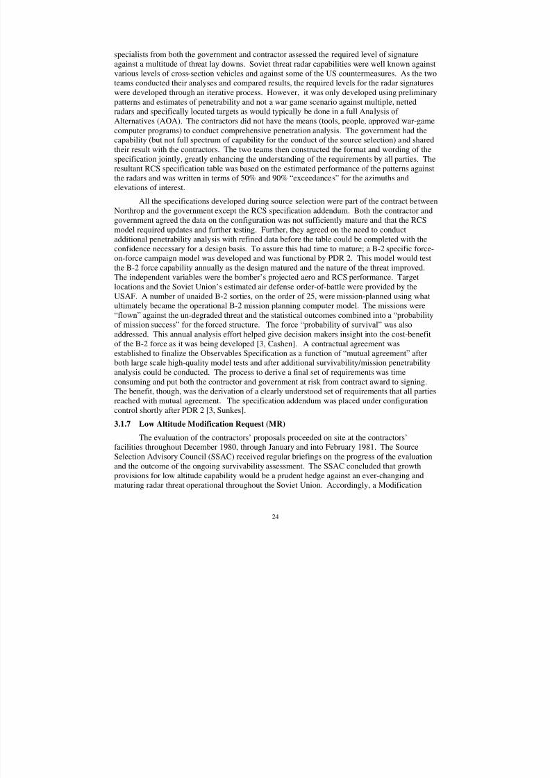
8/3/2019 B-2 Systems Engineering Case Studies
http://slidepdf.com/reader/full/b-2-systems-engineering-case-studies 38/118
24
specialists from both the government and contractor assessed the required level of signatureagainst a multitude of threat lay downs. Soviet threat radar capabilities were well known againstvarious levels of cross-section vehicles and against some of the US countermeasures. As the twoteams conducted their analyses and compared results, the required levels for the radar signatureswere developed through an iterative process. However, it was only developed using preliminary
patterns and estimates of penetrability and not a war game scenario against multiple, nettedradars and specifically located targets as would typically be done in a full Analysis of Alternatives (AOA). The contractors did not have the means (tools, people, approved war-gamecomputer programs) to conduct comprehensive penetration analysis. The government had thecapability (but not full spectrum of capability for the conduct of the source selection) and sharedtheir result with the contractors. The two teams then constructed the format and wording of thespecification jointly, greatly enhancing the understanding of the requirements by all parties. Theresultant RCS specification table was based on the estimated performance of the patterns againstthe radars and was written in terms of 50% and 90% “exceedances” for the azimuths andelevations of interest.
All the specifications developed during source selection were part of the contract between
Northrop and the government except the RCS specification addendum. Both the contractor andgovernment agreed the data on the configuration was not sufficiently mature and that the RCSmodel required updates and further testing. Further, they agreed on the need to conductadditional penetrability analysis with refined data before the table could be completed with theconfidence necessary for a design basis. To assure this had time to mature; a B-2 specific force-on-force campaign model was developed and was functional by PDR 2. This model would testthe B-2 force capability annually as the design matured and the nature of the threat improved.The independent variables were the bomber’s projected aero and RCS performance. Targetlocations and the Soviet Union’s estimated air defense order-of-battle were provided by theUSAF. A number of unaided B-2 sorties, on the order of 25, were mission-planned using whatultimately became the operational B-2 mission planning computer model. The missions were
“flown” against the un-degraded threat and the statistical outcomes combined into a “probabilityof mission success” for the forced structure. The force “probability of survival” was alsoaddressed. This annual analysis effort helped give decision makers insight into the cost-benefitof the B-2 force as it was being developed [3, Cashen]. A contractual agreement wasestablished to finalize the Observables Specification as a function of “mutual agreement” afterboth large scale high-quality model tests and after additional survivability/mission penetrabilityanalysis could be conducted. The process to derive a final set of requirements was timeconsuming and put both the contractor and government at risk from contract award to signing.The benefit, though, was the derivation of a clearly understood set of requirements that all partiesreached with mutual agreement. The specification addendum was placed under configurationcontrol shortly after PDR 2 [3, Sunkes].
3.1.7 Low Altitude Modification Request (MR)
The evaluation of the contractors’ proposals proceeded on site at the contractors’facilities throughout December 1980, through January and into February 1981. The SourceSelection Advisory Council (SSAC) received regular briefings on the progress of the evaluationand the outcome of the ongoing survivability assessment. The SSAC concluded that growthprovisions for low altitude capability would be a prudent hedge against an ever-changing andmaturing radar threat operational throughout the Soviet Union. Accordingly, a Modification
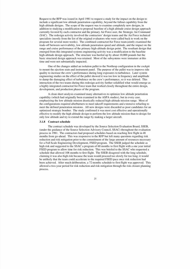
8/3/2019 B-2 Systems Engineering Case Studies
http://slidepdf.com/reader/full/b-2-systems-engineering-case-studies 39/118
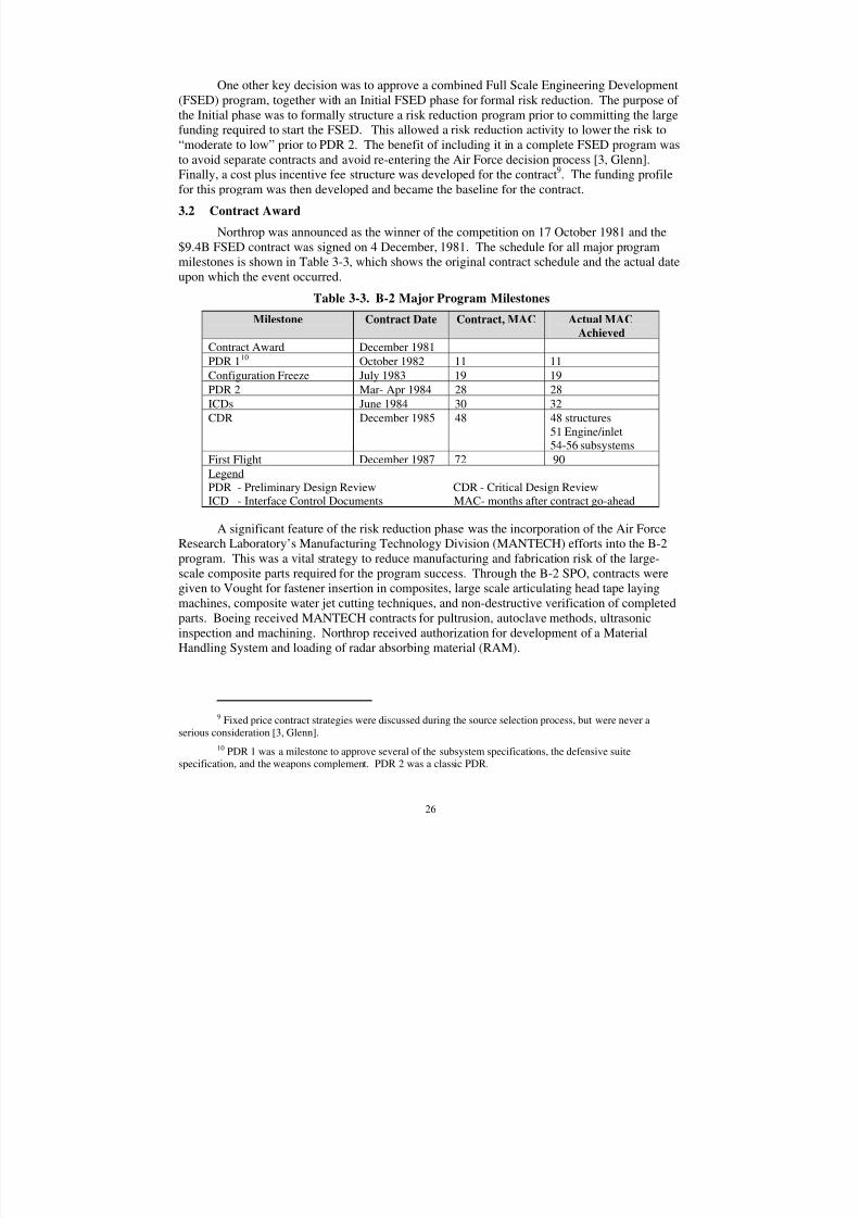
8/3/2019 B-2 Systems Engineering Case Studies
http://slidepdf.com/reader/full/b-2-systems-engineering-case-studies 40/118
26
One other key decision was to approve a combined Full Scale Engineering Development(FSED) program, together with an Initial FSED phase for formal risk reduction. The purpose of the Initial phase was to formally structure a risk reduction program prior to committing the largefunding required to start the FSED. This allowed a risk reduction activity to lower the risk to“moderate to low” prior to PDR 2. The benefit of including it in a complete FSED program was
to avoid separate contracts and avoid re-entering the Air Force decision process [3, Glenn].Finally, a cost plus incentive fee structure was developed for the contract9. The funding profilefor this program was then developed and became the baseline for the contract.
3.2 Contract Award
Northrop was announced as the winner of the competition on 17 October 1981 and the$9.4B FSED contract was signed on 4 December, 1981. The schedule for all major programmilestones is shown in Table 3-3, which shows the original contract schedule and the actual dateupon which the event occurred.
Table 3-3. B-2 Major Program Milestones
Milestone Contract Date Contract, MAC Actual MAC
AchievedContract Award December 1981
PDR 110 October 1982 11 11
Configuration Freeze July 1983 19 19
PDR 2 Mar- Apr 1984 28 28
ICDs June 1984 30 32CDR December 1985 48 48 structures
51 Engine/inlet54-56 subsystems
First Flight December 1987 72 90
LegendPDR - Preliminary Design Review CDR - Critical Design ReviewICD - Interface Control Documents MAC- months after contract go-ahead
A significant feature of the risk reduction phase was the incorporation of the Air ForceResearch Laboratory’s Manufacturing Technology Division (MANTECH) efforts into the B-2program. This was a vital strategy to reduce manufacturing and fabrication risk of the large-scale composite parts required for the program success. Through the B-2 SPO, contracts weregiven to Vought for fastener insertion in composites, large scale articulating head tape layingmachines, composite water jet cutting techniques, and non-destructive verification of completedparts. Boeing received MANTECH contracts for pultrusion, autoclave methods, ultrasonicinspection and machining. Northrop received authorization for development of a MaterialHandling System and loading of radar absorbing material (RAM).
9 Fixed price contract strategies were discussed during the source selection process, but were never aserious consideration [3, Glenn].
10 PDR 1 was a milestone to approve several of the subsystem specifications, the defensive suitespecification, and the weapons complement. PDR 2 was a classic PDR.
8/3/2019 B-2 Systems Engineering Case Studies
http://slidepdf.com/reader/full/b-2-systems-engineering-case-studies 41/118
27
3.2.1 Systems Engineering Organizations
The Air Force System Program Office (SPO) was very interested in a formal systemsengineering organization and formal systems engineering processes that would be defined,documented, and followed by the prime contractor and the two major subcontractors. A formalSystems Engineering Management Plan (SEMP) was not a contract requirement in the original
contract, but the work plans stipulated a formal flowdown of the top level weapons systems requirements into system functional specifications as part of the approved specification tree
11.
The contract required development of six configuration item specifications at a level below theAir Vehicle specification:
• Flight control
• Avionics
• Radar
• Armament
• Low observables
• Software
Systems engineering on the B-2 program was federated with many organizationsparticipating in the execution of the systems engineering process. Described herein are theprimary organizations that existed during the majority of the time frame from program go aheadto one year after CDR. These organizations were instrumental in implementing the systemsengineering process throughout the program, for allocation of requirements, and assuring thedesign WBS Task teams were integrated in their efforts. [3, Griskey]
Weapons Systems Engineering (WSE)
The Weapon Systems Engineering (WSE) organization was established purposefully to
focus on the evaluation of the weapon system’s mission effectiveness, survivability, andvulnerability, and at the same time be the repository for all stealth technology development andevaluations. This unique “marriage” of the classical weapon systems analysis systemengineering functions and the stealth technology design development activities was driven bytwo factors: (1) the fact that the technology development activities were heavily directed by theconstant interchange with the survivability analysis function to assess the “value” of the RCSsignature achieved in the context of the threat systems; and (2) the fact that by combining boththese activity groups into one organization, the Program had consolidated the two generators andrepositories of Level IV, Top Secret data which required special handling and protection even inprogram areas. (The Air Force also organized their functions similarly and they reported to theDirector of Engineering through the Chief Systems engineer.)
The WSE organization consisted of eight separate groups: system analysis; survivabilityanalysis; vulnerability analysis (including nuclear hardening); Low Observables (LO) technologyengineering; LO materials & processes development; LO materials laboratory; anechoiclaboratory; and Grey Butte test range. The last two groups were removed from the B-2 Programchain and became a Division facility for use by the entire Division three years later. The
11 The SEMP in Appendix 5 is reflective of the organization in 1989.
8/3/2019 B-2 Systems Engineering Case Studies
http://slidepdf.com/reader/full/b-2-systems-engineering-case-studies 42/118
28
activities of the six principal organizations are discussed in the following paragraphs. The lattertwo organizations roles are inferred by their titles: the anechoic laboratory was a specific facilitythat could accomplish RCS measurements of specific full-scale, embedded aircraft antennamodels and aircraft full-scale, edge assemblies; and the latter, was a company-owned, test rangewhere small-scale complete aircraft models and large-scale models of specific design features
(e.g. inlets) could be tested on a pole at various bandwidths, polarities, and attitudes.The classical weapon system analysis functions – mission effectiveness, survivability and
vulnerability – were established as separate organizations because of the amount of activity thateach had to perform. The mission effectiveness group was the repository for all threat datafurnished by the USAF’s Foreign Technology Division (FTD) and the “what if” Red Team of scientists that the USAF/RDQ employed at MIT to “challenge” the development team. Themission effectiveness organization developed a “force-on-force” campaign model that was usedto evaluate the effectiveness of the B-2 force capability annually as the design matured and thenature of the threat improved. Target locations and the Soviet Union’s estimated air defenseorder-of-battle were provided in threat documents. A number of unaided B-2 sorties (approx. 25)were mission- planned using what ultimately became the operational B-2 mission planning
computer model. The missions were “flown” against un-degraded threat defensive systems andthe statistical outcomes combined into a “probability of mission success” for the force structure.Force “probability of survival” was also addressed as a function of stealth capability. This annualanalysis effort helped give decision-makers insight into cost-benefit of the B-2 force as it wasbeing developed [3, Cashen].
The survivability analysis group provided support for the mission effectiveness group byproviding “probability of survival” data for the aircraft against each of the defensive systemsindividually, as well as survivability against integrated defensive systems. In addition, the groupprovided data to guide the LO technology development staff to help focus their developmentefforts by identifying where improvements were required against specific threat systems. Thegroup was the repository of all signature data for the B-2 for each signature type: radar crosssection (RCS); infra-red (IR); visual; electromagnetic emissions; and acoustic. The dataincluded: frequency, polarity, and elevation for RCS; wavelength and emissivity for IR;brightness, background, etc. for visual; Low Probability of Intercept RF characterization; anddecibel, range from source, etc. for acoustic. The LO technology group and a series of small,specialty sub-contractors employed by them helped develop the data base as part of the Programeffort.
The vulnerability group had the responsibility to analyze the aircraft design and identifyvulnerable areas against conventional weapons, electromagnetic pulse, etc. This group also hadthe responsibility to assure the design provided “hardening” of the aircraft against nuclearradiation as a function of encountering such an environment as part of conducting a SIOP
mission. To assure this requirement was satisfied; a specialist contractor in nuclear hardeningwas used to augment the Program team. The expanded group reviewed all the detailed design,identified areas for re-design or modification for all vulnerabilities, and reported directly to theChief Engineer and the Program Manager any areas of deficiency. They also established the testrequirement for the special test facility of the USAF for testing nuclear hardness.
The LO Technology group was the group that had total responsibility for defining theaircraft’s external shape that would satisfy the LO requirements and achieve the signature levelsascribed in the contract specification addendum. They had responsibility for advising the design
8/3/2019 B-2 Systems Engineering Case Studies
http://slidepdf.com/reader/full/b-2-systems-engineering-case-studies 43/118
29
organizations on design details that would affect the aircraft’s signature; conducting tests of allexternal features that could affect the signature to verify the design approach; maintaining asignature budget and status report for each major assembly of the aircraft; and reportingperiodically to the senior engineering and program management of both parties. They also hadresponsibility, in conjunction with the LO Materials & Processes development laboratory, to
develop and test all materials and processes used for achieving the signature, in addition toaircraft shaping. For the latter, they had the responsibility, in conjunction with the Aerodynamicsgroup, to ascribe the requirements for shaping the aircraft and “buy-off” of the external moldlines and internal lines of the engine inlet and exhaust ducts defined by the Loft group.
The LO Materials & Processes group had the responsibility for developing and verify allLO materials and processes used in the build of the aircraft. They conducted material reviewswith industry, developed new materials required to achieve solutions to detailed aircraft designissues, and tested the materials and application processes in both the classical “M&P” sense andfor their signature effectiveness. This group was an unsung “hero” of the Program and accountedfor many technology breakthroughs.
Avionics Systems Engineering (ASE)
The avionics systems engineering group continued from their system baseline developedduring the proposal phase and matured the flowdown of requirements from the avionicsequipment and into the other subsystems that provided power, cooling, and other services. Theavionics systems engineering group was responsible for all aspects of the critical itemspecifications within the avionics group and responsible to coordinate and approve othersubsystems specifications and vendor design approaches. They were responsible to allocaterequirements and monitor the progress of other subsystems in meeting the avionics requirements.Avionics also ran their own avionics technical review control board (ATRB) within their groupto make reallocations within their own subsystems without going to the program configurationcontrol board. The head of avionics systems engineering chaired the avionics ATRB up to PDR
2, after which all changes were remanded to the program CCB [3, Conklin]. For the B-2, theavionics architecture drove the weapons system architecture and much of the subsystems designservice requirements.
The avionics systems engineering organization also defined requirements for the flyingtest bed (FTB), a KC 135 bailed by the Air Force to Northrop to install the brass board andbreadboard avionics systems in their early development stage. This outstanding integration toolassisted in early identification of problems, led to early resolution of incompatibilities, andgreatly facilitated the maturity of the avionics suite. The FTB tested much of the equipmentbefore it was flown on the B-2. Systems engineering also derived requirements and built theSystems Integration Laboratory (SIL) at Pico Rivera and managed the testing conducted at thisfacility. The SIL eventually included all the hardware and software operating together prior to
first flight as a further risk reduction to late discovery of system problems.
One founding principle for the design and development process was the extensive use of ground testing in a pyramid from component to subsystem to subassembly to integration.
8/3/2019 B-2 Systems Engineering Case Studies
http://slidepdf.com/reader/full/b-2-systems-engineering-case-studies 44/118
30
Air Vehicle System Engineering (A/V SE)
Air Vehicle System Engineering was organized to encompass air vehicle configurationmanagement in the broadest sense. The responsibility for classic configuration datamanagement was located in the Program Operations and Control organization reporting to theprogram office. The group consisted of the following sub-groups: Configuration Design & Loft;
Flight Sciences; Flight Controls; Structures Technology (incl. External Loads; StructureAnalysis; Structure Dynamics); Mass Properties; Safety Engineering; Human Factors.
Logistics Systems Engineering
The Logistics Organization at Northrop was assigned the classic responsibilitiesassociated with the supportability requirements for a future weapon system. A new feature wasadded to this organization that was unique to the Aerospace industry and clever in its execution.This new feature of the Logistics Systems Engineering group was Reliability and Maintainability(R&M) engineering cognizance. The purpose of this construct was to emphasize the importanceof R&M and elevate its authority. This construct operated exceptionally well by integrating theirpersonnel across the design teams. The Air Force SPO retained R&M responsibility within
engineering. The net effect was that R&M had two voices through the management chain tosurface their issues, effectively raising the importance and reporting levels of the “ilities”. Theprocess achieved a substantial milestone in weapon system reliability for hardware and software,which even today is remarkable for a complex weapon system.
In examining the current maintenance data for the B-2, the bulk of the maintenance effortis performed on the surface treatment to maintain low observability. The systems engineeringprocess noted this was a problem for second or third generation stealth aircraft and includedsurface preparation in the original initial FSED risk reduction/mitigation plan. The state-of-the-art in 1981-1985 when the LO surfaces and treatments were baselined was not as mature ascurrent processes and materials. Today, aircraft are performing much better in this area of LOmaintainability, but the B-2’s performance (higher manhours per flight hours for LO
maintainability) is more a fact of the technology of the mid-1980s than a failure on the systemsengineering process.
The Logistics Systems Engineering group, working in concert with their engineeringcounterparts within Northrop, Boeing, Vought, and from the SPO, established the allocation forsupportability requirements to each subsystem, system element, and the structure assembly.They established design criteria based on lessons learned from similar equipments; assuredinclusion of supportability requirements into all procurement specifications; establishedreliability growth test criteria for all system complements; closely monitored the progress of subcontractor and vendor designs and testing. This group also developed the specifications forall automated test and training equipment, and simulators and directed the development of the
new support process for maintaining low observables in the field. This group was a veryeffective part of the program systems engineering process. Much of the success for the achievedR&M for the hardware and software can be attributed to this group.
Lastly, there was an additional feature that had a very large impact on the design anddevelopment of the B-2 weapon system - Primary System Reliability (PSR). The establishmentof a very ambitious level of PSR, combined within the logistics systems engineering construct,were the two primary factors contributing to the demonstrated system reliability. PSR was suchan overwhelming and difficult requirement to achieve, it may well have been the single most
8/3/2019 B-2 Systems Engineering Case Studies
http://slidepdf.com/reader/full/b-2-systems-engineering-case-studies 45/118
31
difficult of all the requirements, overshadowing even radar cross-section. The basic PSRrequirement stipulated in the System Specification was a 90% probability that the last weapon of the suite of missions had to be delivered within the required circular error probability (CEP).This was an enormously difficult requirement to meet. The requirement was derived from theSAC mission criterion that computes how and what type of weapon is assigned to specific
targets. The algorithm computes the probability of damage given such factors as the probabilityof a successful strike and the reliability of the weapon. The process to allocate this very difficultrequirement necessitated each and every subsystem to design for very high reliability and anadded degree of redundancy. During operations in the Balkans, the B-2 demonstrated a PSR of 0.89 [5].
Vought Systems Engineering
Vought organized their engineering staff into a classic project organization with a systemengineering office and lead project WBS Task Team leaders reporting directly to the chief engineer. The function for the intermediate wing was primarily structures, zone management,composite design and construction, interface management, and subsystems routing ininstallation. Vought had two major development responsibilities; they had to develop & provethe process for fabrication and assembly of the inlet assembly and they had to develop and testand verify the concept for cooling the aft deck assembly. The requirements were derivedrequirements from their specification and ICD’s with Northrop and Boeing. Vought’sorganization was not fully implemented as an IPT structure because they stopped short of assigning cross-functional people to the project lead.
Boeing Company Systems Engineering
Boeing organized its program structure in a form that met the B-2 Program needs andincorporated its previous experience in both Military and Commercial programs. A SystemsEngineering function was established from the very beginning. A senior Program SE managerwas assigned. His role included several functions: Systems Engineering integration,
coordination with Northrop and the significant contractors, such as Vought, technicalspecifications and interface control document management, and overall program technicalintegration, including our business and contracts functions. Boeing had specific areas of responsibility: outboard wing, aft center wing, landing gear, fuel system, offensive avionics,weapon launchers, and integration. Each area had its own sub-team management. There was ahuge effort to integrate with the rest of the B-2 program using the WBS Task team structure.Each area had its systems engineering team. The leaders of these sub-teams reported both totheir chief engineers and to the Program Systems Engineering Manager. The work was verycomplex. The nature of the work started at the typical product definition, requirements flowdown and Spec/ICD level, then phased into very detailed activity, and finally into demonstratingcompliance with all technical, form, fit, and function requirements. The reconfiguration and
ensuing changes to the internal systems affected the work. Fully stuffed structure, stealthimplications, internal avionics tie integration, software, etc created a demanding environment toassure internal and external integration by the SE group. The aircraft would have not beensuccessful without the System Engineering function [3, Spitzer].
Air Force SPO Systems Engineering
The original B-2 engineering team during the source selection consisted of 35 engineers.As those 35 engineers migrated back to their original program offices, new personnel were
8/3/2019 B-2 Systems Engineering Case Studies
http://slidepdf.com/reader/full/b-2-systems-engineering-case-studies 46/118
32
assigned to the program to manage the development activity. As new engineers were assigned,the original lead engineer for the technical discipline would accompany his (her) replacement tomeet their contractor counterpart. This facilitated the continuation of the already establishedworking relationship forged during the source selection process and assured a continuation of this philosophy.
The SPO Engineering Directorate was a classical organizational structure with fourdivisions:
• Systems Engineering
• Airframe
• Avionics
• Crew Station
The Chief Engineer, (later elevated to the Director of Engineering) always had a deputychief engineer. The people integrated their efforts with the other SPO Directorates at theworking level and always worked closely with their Projects Directorate counterparts.
The program progressed from the initial full-scale development program and the risk reduction areas to a full-fledged, fast-paced development program by the time of thereconfiguration in the middle of 1984. The SPO engineering cadre grew to 60 people by early1985 and still consisted of highly experienced, well-trained engineers with exceptionally strongbackgrounds and experience. The process to staff the SPO at the time of contract award wasinteresting and effective.
An engineer would receive a phone call from the secretary of Mr. Fred Rall, the technicaldirector for Aeronautical Systems Center. Bessie would tell the engineer that he (she) wasneeded for a meeting in Mr. Rall’s office at 2 p.m. tomorrow. The engineer would show uptypically 15 minutes ahead of time and wait on the couch until 2 p.m. The door to Mr. Rall’s
office would be closed and no one would go in or out. At 2 p.m., Bessie would tell the engineerit was okay to go into the room. No one would be there but the B-2 chief engineer, who himself no longer existed on any organization chart. He would be sitting in Mr. Rall’s chair at theconference table. After the engineer looked around and saw no one else was in the room, theywould be asked to sit down. The chief engineer would explain that the person was wanted in the“black hole” for a project. They would ask what they would be doing and receive the answer, “Ican’t tell you”. They would ask numerous questions, all receiving the same answer! Afterseveral minutes of this, and there would be a resigned sigh and finally, after being assured it wasa great program and an important job, every single one said, “okay”. After the agreement, theyhad a short period of time to close any actions ongoing in their past assignment before reportingto the black hole and essentially disappearing from the organization chart. The engineering
functional (ASC/EN home office) still kept their records but they were co-located and not shownon any other organizational chart. It was the responsibility of the chief engineer and Mr. Rall’sstaff to assure that the engineers received their promotions and performance increases consistentwith their performance in the B-2 SPO. Since these engineers were among some of the best,they regularly competed for and won bonuses and promotions. This helped assure that newengineers would be willing to be assigned to the SPO because they knew they could still competewith their unclassified program (“white world”) counterparts on an equal basis.
8/3/2019 B-2 Systems Engineering Case Studies
http://slidepdf.com/reader/full/b-2-systems-engineering-case-studies 47/118
33
It was essential to continue to staff the B-2 SPO with experienced engineers whounderstood their technical discipline and the role of requirements in development programs.These people were committed to cooperate with each other, with the contractors, and with theuser to develop a balanced design and to make and implement the decisions required to make thisweapons system development successful. During design reviews at the working level, the
engineers from the SPO would regularly attend the meetings and assist in the process. The usingcommand was also invited to design review meetings and technical interchange meetings andthey attended on a regular basis. SAC had a staff of about 20 officers stationed at SACheadquarters in Omaha Nebraska who were assigned to the program with responsibility of acontinuous presence in the program. These officers played a vital role in helping the engineersunderstand the conduct of the SAC mission and the needs of the crew and maintenance people.The SPO engineers helped the using command personnel understand the implications of requirements that exceed that which would be required to satisfactorily conduct operations. Theconstant interaction of the three groups, SAC stating their needs, the SPO defining requirements,and the contractor teams designing and developing the hardware and software was a keyingredient in the operation of the process.
Chief Engineers Meetings
The company chief engineers and the Air Force SPO chief engineer met every four to sixweeks for a one-day meeting. The purpose of these meetings was to rapidly resolve integrationand design issues. The meeting host was rotated between the chief engineer for Northrop,Boeing, Vought, and the Air Force. Responsible engineers and their team for a particular areaunder study would brief the problem and alternatives. The team would consist of membershipfrom all the companies and the SPO. The decision was made as to how best to proceed and thechief engineers agreed to implement the decision immediately. It was responsibility of eachchief engineer to assure the decision was communicated to the program manager and throughouthis or her own organization; it was also their responsibility to insure contractual integrity of thedecision.
These meetings were a highly effective systems engineering process tool. Prior to themeetings, significant integration effort and assessment of alternatives was required by the staff topresent a sound solution to the program engineering leadership. None of the engineers wanted topresent an incomplete resolution in this forum. This was essentially a technical configurationcontrol board although each of the design teams had dedicated contracts, financial management,manufacturing, and logistics membership as part of their team. This facilitated communicationsand contract efforts to implement the decisions.
There were other major subcontractors that also became involved in the chief engineersmeetings particularly Hughes and General Electric. The Hughes contract was a subcontract toNorthrop and the General Electric contract was managed by the SPO for the basic engine.
Northrop also had a separate contract with GE for the design and development of the exhaustnozzle/tailpipe. The working relationships with these two contractors, and in fact, all of thesubcontractors and vendors were excellent and consistent with the working relationships amongthe four main entities.
3.2.2 Facilitization
The B-2 program scope was so large that conducting the program within a singleaerospace corporation was considered impractical. The program started at the same time the
8/3/2019 B-2 Systems Engineering Case Studies
http://slidepdf.com/reader/full/b-2-systems-engineering-case-studies 48/118
34
Aerospace industry was in a general boom. In the Los Angeles basin, several aerospacecorporations were vying for the engineering talent. During the source selection Lockheed hadannounced they would team with Rockwell even though Rockwell was preparing a proposal todevelop and build 100 B-1B’s in response to Reagan’s campaign promise to restart the program.Northrop’s corporate team included Boeing and Vought and was considered a viable competitor
even though Northrop had not been a prime contractor on a large bomber program since B-35/B-49 flying wings in the 1940s. They had been the prime contractor for the T- 38/F-5 programsand considered themselves a “fighter house”. It had taken several persuasive conversationsbetween the Air Force senior leadership, Lt. Gen. Stafford, and the CEO of Northrop, TomJones, before Northrop agreed to participate in the 1980 study contract that founded the B-2.
The full-scale development program required a significant infrastructure expansion fromthe very beginning for facilities, capital equipment, laboratories, staff, and security. All three of the ma jor corporations undertook a substantial capital investment program that exceeded $2.5billion12. A brief description is provided in order to capture the magnitude of theseinvestments13.
Northrop Facility Capitalization
Two separate office buildings were constructed to house material procurement,subcontract management organizations, facilities engineering, and the operations organization.Expansion of the outdoor radar cross-section range modernized the capability to increase dataproduction rates. A large (2.5 million square foot ex-Ford plant) was acquired, gutted, andequipped to house a new Northrop Division. The new secure facility at Pico Rivera, Californiawas required for design, development, research, laboratory testing, and sub assembly of theForward Center Wing and all the edge structures. Program Management and all the majorfunctional managers from the program also had their offices in this central location. This facilityprovided:
• Workstations and offices for 2,500 engineers, scientists, and support staff
• Dedicated computer complex and computer design rooms
• Flight simulation laboratory with accommodations for a full-scale iron bird
• Avionics laboratory for display development
• Workstations for individual avionics software development and hot benches forhardware/software integration
• An integrated Avionics and Flight Control Laboratory
• Model shops (wind tunnel and radar cross-section models)
• Anechoic chambers
12 All indemnified by the DOD/USAF.
13 One of the pre-contract events that had a significant impact on the cost of the program was the effect of security. Security was listed as the first priority in the government Program Management Directive, PMD. Theremaining order of priority was technical, schedule, and then cost. During the 1980-1981 timeframe, a new programsecurity guide was implemented by the DOD for special access programs, which increased the cost of maintainingsecurity by requiring new procedures. This was to have a profound cost impact, later assessed at 15 to 20 percent of the total program cost, little of which was included in the original cost estimate.
8/3/2019 B-2 Systems Engineering Case Studies
http://slidepdf.com/reader/full/b-2-systems-engineering-case-studies 49/118
35
• Composite fabrication and sub assembly facility, including clean rooms
• Manufacturing facility with automated material, tool handling, and inventorystorage system
• Five autoclaves
• A major structural assembly area for the Forward Center Wing assembly.
Northrop accepted responsibility for the design, construction, and acceptance of a securefinal assembly facility at Palmdale as part of their Total System Performance Responsibility(TSPR) by executing a separate contract obligation with the Air Force. Northrop wasresponsible to equip the building at Site 4 of Plant 42 in Palmdale to accomplish the integrationand final assembly, system checkout, engine run-up, and taxi testing. The company was alsoresponsible for modification of a building to provide for the aircraft’s surface preparation andcoatings applications.
Boeing Facility Capitalization
Modifications were made to major portions of the existing Development Center at the
Seattle Boeing Field location to accommodate the design, development, and production of theAft Center Wing and the Outboard Wings. This included:
• Workstations and space for 1,200 – 1,300 engineers, scientists, and supportpersonnel
• Full-scale mock up areas for their sub assemblies
• Structural test laboratory
• Armaments laboratory for the development of the rotary launcher
• Office space for the managers
•
Development and installation of the world’s largest autoclave (125 ft by 25 ft);• A composite pultrusion facility
• Large-scale composite skin bond assembly capability
• Fuel laboratory was updated to test the entire fuel system on a fuel table capableof rotating to simulate in-flight attitudes
Vought Facility Capitalization
Modifications were also made to Vought facilities. These consisted of:
• An office building to accommodate a dedicated computer complex
•
Offices and workstations for approximately 750 engineers and support personnel• Modification of the metal fabrication facility to accommodate automated handling
of working process and raw material distribution
• Modification of assembly building to accommodate design development andproduction of the Intermediate Wing; design development and installation of acomposite tape laying machine to construct three-dimensional surfaces
• Installation of a drive-matic machine for titanium fasteners
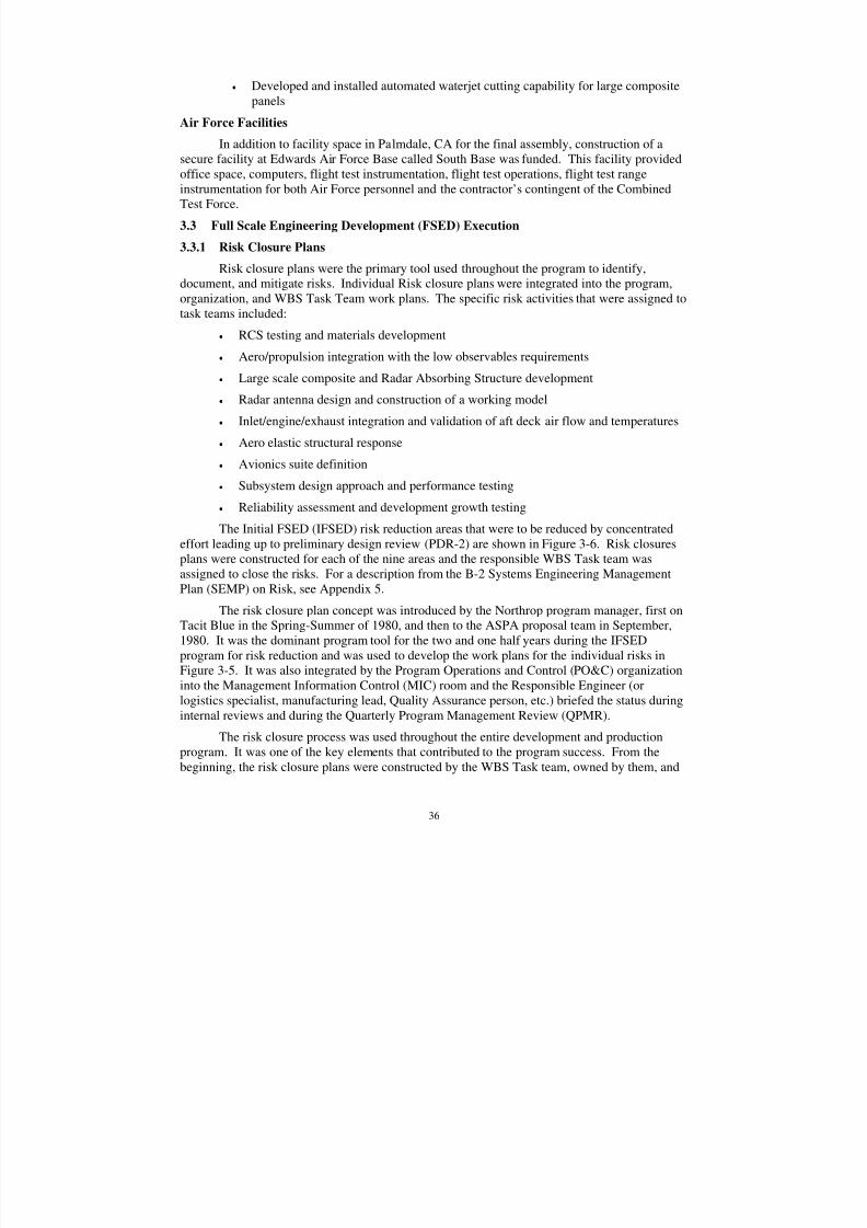
8/3/2019 B-2 Systems Engineering Case Studies
http://slidepdf.com/reader/full/b-2-systems-engineering-case-studies 50/118
36
• Developed and installed automated waterjet cutting capability for large compositepanels
Air Force Facilities
In addition to facility space in Palmdale, CA for the final assembly, construction of asecure facility at Edwards Air Force Base called South Base was funded. This facility providedoffice space, computers, flight test instrumentation, flight test operations, flight test rangeinstrumentation for both Air Force personnel and the contractor’s contingent of the CombinedTest Force.
3.3 Full Scale Engineering Development (FSED) Execution
3.3.1 Risk Closure Plans
Risk closure plans were the primary tool used throughout the program to identify,document, and mitigate risks. Individual Risk closure plans were integrated into the program,organization, and WBS Task Team work plans. The specific risk activities that were assigned totask teams included:
• RCS testing and materials development
• Aero/propulsion integration with the low observables requirements
• Large scale composite and Radar Absorbing Structure development
• Radar antenna design and construction of a working model
• Inlet/engine/exhaust integration and validation of aft deck air flow and temperatures
• Aero elastic structural response
• Avionics suite definition
• Subsystem design approach and performance testing
• Reliability assessment and development growth testing
The Initial FSED (IFSED) risk reduction areas that were to be reduced by concentratedeffort leading up to preliminary design review (PDR-2) are shown in Figure 3-6. Risk closuresplans were constructed for each of the nine areas and the responsible WBS Task team wasassigned to close the risks. For a description from the B-2 Systems Engineering ManagementPlan (SEMP) on Risk, see Appendix 5.
The risk closure plan concept was introduced by the Northrop program manager, first onTacit Blue in the Spring-Summer of 1980, and then to the ASPA proposal team in September,1980. It was the dominant program tool for the two and one half years during the IFSEDprogram for risk reduction and was used to develop the work plans for the individual risks inFigure 3-5. It was also integrated by the Program Operations and Control (PO&C) organizationinto the Management Information Control (MIC) room and the Responsible Engineer (orlogistics specialist, manufacturing lead, Quality Assurance person, etc.) briefed the status duringinternal reviews and during the Quarterly Program Management Review (QPMR).
The risk closure process was used throughout the entire development and productionprogram. It was one of the key elements that contributed to the program success. From thebeginning, the risk closure plans were constructed by the WBS Task team, owned by them, and
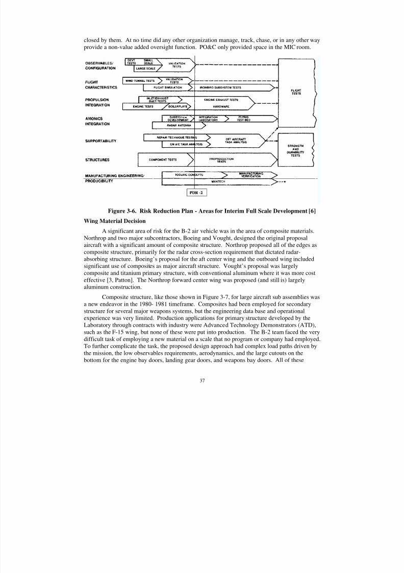
8/3/2019 B-2 Systems Engineering Case Studies
http://slidepdf.com/reader/full/b-2-systems-engineering-case-studies 51/118
37
closed by them. At no time did any other organization manage, track, chase, or in any other wayprovide a non-value added oversight function. PO&C only provided space in the MIC room.
Figure 3-6. Risk Reduction Plan - Areas for Interim Full Scale Development [6]
Wing Material Decision
A significant area of risk for the B-2 air vehicle was in the area of composite materials.Northrop and two major subcontractors, Boeing and Vought, designed the original proposalaircraft with a significant amount of composite structure. Northrop proposed all of the edges ascomposite structure, primarily for the radar cross-section requirement that dictated radar-absorbing structure. Boeing’s proposal for the aft center wing and the outboard wing includedsignificant use of composites as major aircraft structure. Vought’s proposal was largelycomposite and titanium primary structure, with conventional aluminum where it was more costeffective [3, Patton]. The Northrop forward center wing was proposed (and still is) largelyaluminum construction.
Composite structure, like those shown in Figure 3-7, for large aircraft sub assemblies wasa new endeavor in the 1980- 1981 timeframe. Composites had been employed for secondary
structure for several major weapons systems, but the engineering data base and operationalexperience was very limited. Production applications for primary structure developed by theLaboratory through contracts with industry were Advanced Technology Demonstrators (ATD),such as the F-15 wing, but none of these were put into production. The B-2 team faced the verydifficult task of employing a new material on a scale that no program or company had employed.To further complicate the task, the proposed design approach had complex load paths driven bythe mission, the low observables requirements, aerodynamics, and the large cutouts on thebottom for the engine bay doors, landing gear doors, and weapons bay doors. All of these
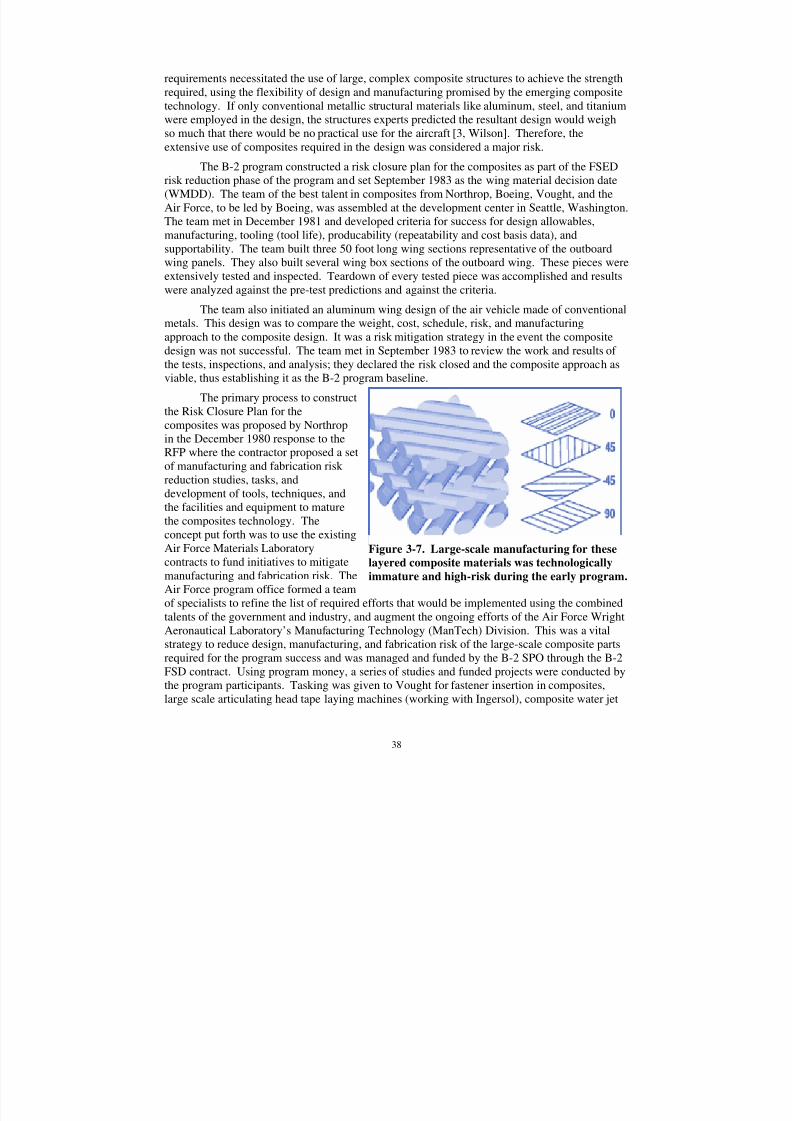
8/3/2019 B-2 Systems Engineering Case Studies
http://slidepdf.com/reader/full/b-2-systems-engineering-case-studies 52/118
38
requirements necessitated the use of large, complex composite structures to achieve the strengthrequired, using the flexibility of design and manufacturing promised by the emerging compositetechnology. If only conventional metallic structural materials like aluminum, steel, and titaniumwere employed in the design, the structures experts predicted the resultant design would weighso much that there would be no practical use for the aircraft [3, Wilson]. Therefore, the
extensive use of composites required in the design was considered a major risk.The B-2 program constructed a risk closure plan for the composites as part of the FSED
risk reduction phase of the program and set September 1983 as the wing material decision date(WMDD). The team of the best talent in composites from Northrop, Boeing, Vought, and theAir Force, to be led by Boeing, was assembled at the development center in Seattle, Washington.The team met in December 1981 and developed criteria for success for design allowables,manufacturing, tooling (tool life), producability (repeatability and cost basis data), andsupportability. The team built three 50 foot long wing sections representative of the outboardwing panels. They also built several wing box sections of the outboard wing. These pieces wereextensively tested and inspected. Teardown of every tested piece was accomplished and resultswere analyzed against the pre-test predictions and against the criteria.
The team also initiated an aluminum wing design of the air vehicle made of conventionalmetals. This design was to compare the weight, cost, schedule, risk, and manufacturingapproach to the composite design. It was a risk mitigation strategy in the event the compositedesign was not successful. The team met in September 1983 to review the work and results of the tests, inspections, and analysis; they declared the risk closed and the composite approach asviable, thus establishing it as the B-2 program baseline.
The primary process to constructthe Risk Closure Plan for thecomposites was proposed by Northropin the December 1980 response to the
RFP where the contractor proposed a setof manufacturing and fabrication risk reduction studies, tasks, anddevelopment of tools, techniques, andthe facilities and equipment to maturethe composites technology. Theconcept put forth was to use the existingAir Force Materials Laboratorycontracts to fund initiatives to mitigatemanufacturing and fabrication risk. TheAir Force program office formed a team
of specialists to refine the list of required efforts that would be implemented using the combinedtalents of the government and industry, and augment the ongoing efforts of the Air Force WrightAeronautical Laboratory’s Manufacturing Technology (ManTech) Division. This was a vitalstrategy to reduce design, manufacturing, and fabrication risk of the large-scale composite partsrequired for the program success and was managed and funded by the B-2 SPO through the B-2FSD contract. Using program money, a series of studies and funded projects were conducted bythe program participants. Tasking was given to Vought for fastener insertion in composites,large scale articulating head tape laying machines (working with Ingersol), composite water jet
Figure 3-7. Large-scale manufacturing for these
layered composite materials was technologically
immature and high-risk during the early program.
8/3/2019 B-2 Systems Engineering Case Studies
http://slidepdf.com/reader/full/b-2-systems-engineering-case-studies 53/118
39
cutting techniques, non-destructive test and verification of completed parts. Boeing developedprocesses and equipment for pultrusion, autoclave methods, autoclave control systems, ultrasonicinspection, and tape laying equipment with Cincinnati Milacron. Hughes received Mantechmoney to build new antenna mechanically scanned in one direction, electronically scanned in theorthogonal direction. Northrop was funded for their large scale edge design and manufacturing
facility. This process to reduce risk and mature the state of the art in manufacturing also had apositive effect on the overall design because the manufacturing process was maturing with theengineering. Manufacturing and the logistics functionals (through the emphasis on reliability,maintainability, and supportability) were well represented in the early design process in theprogram. The ManTech efforts with the B-2 contractors were conducted during 1981 to 1985.
3.3.2 Preliminary Design Review (PDR-1)
PDR 1 incorporated two new, major engineering activities, both of which had significantchanges to the baseline configuration. The first of these changes resulted from the culminationof the avionics suite defensive countermeasure study. Avionics systems engineering and theavionics contingent from the Air Force SPO had been conducting a trade studies on variousdefensive suite alternatives as an enhancement to the penetration of Soviet defenses. The studyexamined survivability enhancement through the use of countermeasures specifically applicableto stealth vehicles. The study results were completed at PDR 1 and formally presented to the AirForce SPO and the recommended avionics suite was approved. The approved suite became partof the new avionics program baseline and was incorporated in the avionics specifications.
The second change was the incorporation of certain provisions for a third crewmember.Mission proficiency and crew workload studies were conducted after contract award and showedthat with the combination of penetration aids, mission planning software, display algorithms,automation, and redundancy, a two-man crew was fully adequate to complete the specifiedmissions. However, the Air Force planners reasoned that new missions and unforeseencomplexities in the future may well force an increase in workload to the point where a third
crewmember would be necessary. Therefore, after an extensive trade study was conducted in themonths leading up to PDR 1, the SPO decided to incorporate space and structural provisions forthe third crewmember. This necessitated moving the avionics that was currently installed in theaft part of the crew station to a new location in the aft of the aircraft, behind the weapons bays.The upper section of the aft crew station bulkhead was canted backwards at the angle of the back of the ejection seat to allow for the installation of the seat rails. This further resulted in movingweapons bay rotatory launchers back slightly to allow for weapon clearance for this new cantedbulkhead.
A major integration tool that started to emerge after contract award and eventuallyachieved program wide acceptance was computer aided design and classified networking.NCAD/NCAL was a Northrop Computer Aided Design (NCAD)/ Northrop Computer Aided
Lofting (NCAL) tool developed under independent R&D that was extremely effective and usefulfor the task of integrating all the companies and their design staffs. It was a major aide to thesystems engineering process. The system was user friendly, very capable, and easily adaptableto a classified network among the companies. While CAD tools are commonplace now, thistechnology did not exist in the early 1980s; the B-2 was the first all-CAD designed aircraft [3,Myers]. Its ease of use and simplicity facilitated the design evolution, spatial allocations,requirement tradeoffs, was a great aid to integration across the interfaces, and a boon to the easeof integration of the assemblies during manufacturing.
8/3/2019 B-2 Systems Engineering Case Studies
http://slidepdf.com/reader/full/b-2-systems-engineering-case-studies 54/118
40
3.3.3 Configuration Freeze
The next major milestone after PDR-1 was “Configuration Freeze,” scheduled ninemonths prior to PDR-2. It was one of the last “Configuration-Driver” risk closure activities stillopen from the Interim FSED risks. It was four and one half months prior to this contractor-imposed milestone that the need for a major redesign became apparent. The redesign would be
the largest single internal event that occurred during development and contributed both to the slipin the first flight date and to the cost increase of the program.
The Pre-contract award Modification Request for high subsonic, low altitude penetrationcapability imposed a derived requirement for an additional low altitude gust capability. Theteam recognized that the higher gust loads and more severe spectrum would have a majorinfluence on the structural design loads. The team developed a sophisticated model of thecomplex aero-servo-elastic characteristics of the air vehicle, including steady and unsteadyaerodynamics, structural dynamics (derived from a NASTRAN finite element model), as well asthe flight control laws and actuation dynamics in order to quantify the achievable level of gustload alleviation. This integrated structural analysis program would confirm the internal loadsconcurrently while controlling the aircraft. The program was to be a key factor in assessing theadequacy of the structural design during operations at low altitude/high speed operations in thepresence of significant gust loads. In particular it would assess the adequacy of the flight controlsystem to actively reduce the airframe’s dynamic response. Northrop drew on the expertise andhelp of national scientific and technology leaders from USAF, NASA, members of all threeairframe companies’ technical staffs, and both General Electric and Minneapolis Honeywell’sAdvanced Design Center to facilitate the development of the analytical program14.
The analysis was scheduled for completion in December 1982 but because of itscomplexity, it was not yielding data until January 1983. Meaningful results were obtained inearly February 1983 at which time Air Vehicle Systems Engineering (A/V S/E) WBS task teamleader advised the Northrop program manager that the results revealed a substantial wing
bending moment increase over earlier estimates due to more severe aero-elastic effects incurredat high speed, low altitude flight conditions and the inability of the controls to provide adequateload alleviation, while still controlling flight and maneuvers. Eighty percent of the wing bendingmoment came from the first bending mode, which had a node line that curved behind theoutboard controls as depicted in Figure 3-7.
The center of pressure for the primary pitch control surfaces was nearly coincident withthe first wing bending node line. This reduced the effectiveness of the control system to dampthe gust induced loads associated with this mode. The analysis also revealed that distribution of the carry through loads across the centerline was strongly asymmetric with the forward weaponbay bulkhead receiving 70 percent of the total root bending moment, leaving only 30 percentthrough the rear bulkhead. The combination of increased bending moment and poor load
distribution led to high internal loads in the inboard forward wing structure. The inefficient foreand aft load paths were brought about in part, because of the large cutout in the bottom of theaircraft for the weapons bay doors, engine bay doors, and landing gear doors. While the cutoutswere there from the beginning and the team knew they would affect the ability to control the
14 Of particular note were the significant contributions made by Dick Stone of Minneapolis Honeywell andJerry Newsom and John Edwards of NASA Langley
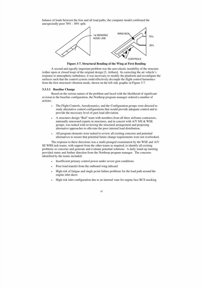
8/3/2019 B-2 Systems Engineering Case Studies
http://slidepdf.com/reader/full/b-2-systems-engineering-case-studies 55/118
41
balance of loads between the fore and aft load paths, the computer model confirmed theunexpectedly poor 70% - 30% split.
1st BENDING
NODE LINE
70%
30%
WING BOX
CONTROLS
Figure 3-7. Structural Bending of the Wing at First Bending
A second and equally important problem was the aero-elastic instability of the structure(either open or closed loop) of the original design [3, Arthurs]. In correcting the air vehicle’sresponse to atmospheric turbulence, it was necessary to modify the planform and reconfigure thesurfaces such that the control system could effectively decouple the flight control harmonicsfrom the first structural vibration mode, shown on the left side graphic in Figure 3-7.
3.3.3.1 Baseline Change
Based on the serious nature of the problem and faced with the likelihood of significantrevision to the baseline configuration, the Northrop program manager ordered a number of actions:
• The Flight Controls, Aerodynamics, and the Configuration groups were directed tostudy alternative control configurations that would provide adequate control and toprovide the necessary level of gust load alleviation.
• A structures design “Red” team with members from all three airframe contractors,nationally renowned experts in structures, and in concert with A/V S/E & WSEgroups, was tasked with reviewing the structural arrangement and proposingalternative approaches to alleviate the poor internal load distribution.
• All program elements were tasked to review all existing concerns and potentialalternatives to ensure that potential future change requirements were not overlooked.
The response to these directions was a multi-pronged examination by the WSE and A/VSE WBS task teams, with support from the other teams as required, to identify all existingproblems or concerns and generate and evaluate potential solutions. A daily stand-up meetingprovided status and further direction from the Northrop program manager. The concerns
identified by the teams included:
• Insufficient primary control power under severe gust conditions
• Poor load transfer from the outboard wing inboard
• High risk of fatigue and single point failure problems for the load path around theengine inlet ducts
• High risk inlet configuration due to an internal vane for engine face RCS masking
8/3/2019 B-2 Systems Engineering Case Studies
http://slidepdf.com/reader/full/b-2-systems-engineering-case-studies 56/118
42
• Severe high angle of attack static and dynamic instability due to the effects of the fullspan, sharp leading edge of the wing.
3.3.3.2 Controllability
The flight control system for the B-2 had the dual function of controlling the aircraft’s
flight path and providing active gust load alleviation. The analysis results in early 1983indicated adequate aero-elastic control margins in smooth air, but insufficient control power toachieve the required level of gust load alleviation. Since the trailing edge controls provided bothpitch and roll, this affected both the pitch and roll control margins. Solving the controllabilityissue would require moving or adding pitch controls inboard of the wing first bending node line,namely, inboard of the trailing edge notch. Alternative arrangements were generated for analysisand rapid low speed wind tunnel evaluation. The inboard wing trailing edge area dominated bythe engine exhaust was considered unsuitable for adding controls. The remaining span of thebaseline planform could not provide the necessary control effectiveness. It was determined thatmodification of the trailing edge by addition of an extra notch would accommodate new inboardcontrol surfaces. Alternative control surface arrangements were tested in the wind tunnel and on
the RCS test range. By the first of May 1983, the testing confirmed a configuration thatprovided both high control effectiveness and low RCS risk. The new inboard controls providedcontrol effectiveness for both pitch and roll functions while the outboard control surfaces wouldbe utilized to primarily augment low speed roll control. The new control scheme provided abalance of control power for maneuvers and effective gust load alleviation.
The structural load/flight control analysis of the gusts input revealed the aircraft’s pitchinstability yielded an open loop time to double amplitude at these conditions on the order of 100milliseconds. This necessitated an immediate response from the control surface and resulted in aderived requirement to provide large, high rate surfaces. It was determined that the no-load ratefor the large inboard controls should be 100 degrees/second which, coupled with their largehinge moments, would require adding an additional hydraulic pump to each engine (two pumps
per engine). This also necessitated a change to the air data system. Since the feedback from themeasured air vehicle angle of attack was crucial to gust load alleviation, the air data system wasmoved closer to the aircraft leading edge to reduce the sensing time delay.
An additional controllability issue was a low speed lateral-directional cross couplingconcern due to development of leading edge vortex flow at high angles of attack that causeddecay in outboard control surface effectiveness. Aerodynamics indicated that leading edgerounding could alleviate the situation and the LO engineers were asked to examine thepossibility. They indicated a theoretical basis for acceptance of the change as long as the edgewas sharp at the tip and center. That feature is readily seen in the airplane today. Afterexperimental verification, a wing leading edge shape was developed and accepted whichinhibited vortex formation and maintained flow energy over the outboard aileron. This was anenormously important change to the aerodynamics and stability and control of the vehiclebecause it provided a piecewise linear set of stability derivatives for the control systemsdesigners.
3.3.3.3 Inlet
An ongoing problem with the baseline configuration inlet was a requirement for aninternal vane to mask engine face from radar detection. The vane design had started as a thin
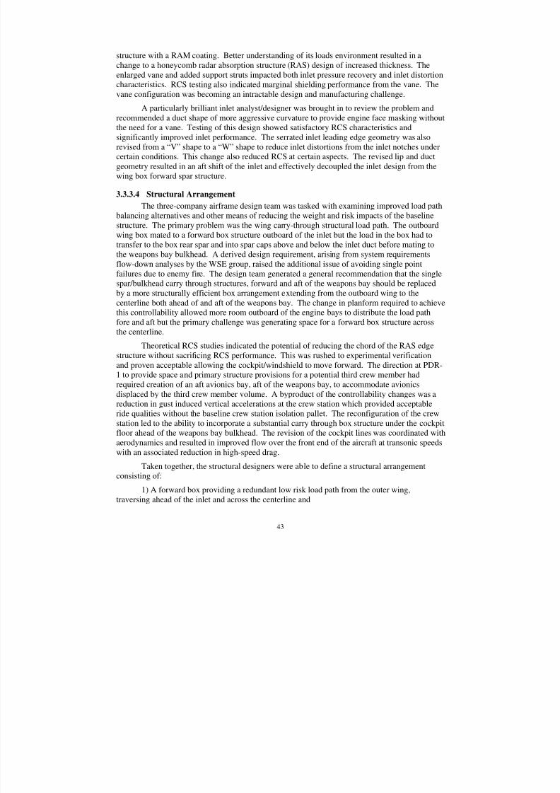
8/3/2019 B-2 Systems Engineering Case Studies
http://slidepdf.com/reader/full/b-2-systems-engineering-case-studies 57/118
43
structure with a RAM coating. Better understanding of its loads environment resulted in achange to a honeycomb radar absorption structure (RAS) design of increased thickness. Theenlarged vane and added support struts impacted both inlet pressure recovery and inlet distortioncharacteristics. RCS testing also indicated marginal shielding performance from the vane. Thevane configuration was becoming an intractable design and manufacturing challenge.
A particularly brilliant inlet analyst/designer was brought in to review the problem andrecommended a duct shape of more aggressive curvature to provide engine face masking withoutthe need for a vane. Testing of this design showed satisfactory RCS characteristics andsignificantly improved inlet performance. The serrated inlet leading edge geometry was alsorevised from a “V” shape to a “W” shape to reduce inlet distortions from the inlet notches undercertain conditions. This change also reduced RCS at certain aspects. The revised lip and ductgeometry resulted in an aft shift of the inlet and effectively decoupled the inlet design from thewing box forward spar structure.
3.3.3.4 Structural Arrangement
The three-company airframe design team was tasked with examining improved load path
balancing alternatives and other means of reducing the weight and risk impacts of the baselinestructure. The primary problem was the wing carry-through structural load path. The outboardwing box mated to a forward box structure outboard of the inlet but the load in the box had totransfer to the box rear spar and into spar caps above and below the inlet duct before mating tothe weapons bay bulkhead. A derived design requirement, arising from system requirementsflow-down analyses by the WSE group, raised the additional issue of avoiding single pointfailures due to enemy fire. The design team generated a general recommendation that the singlespar/bulkhead carry through structures, forward and aft of the weapons bay should be replacedby a more structurally efficient box arrangement extending from the outboard wing to thecenterline both ahead of and aft of the weapons bay. The change in planform required to achievethis controllability allowed more room outboard of the engine bays to distribute the load path
fore and aft but the primary challenge was generating space for a forward box structure acrossthe centerline.
Theoretical RCS studies indicated the potential of reducing the chord of the RAS edgestructure without sacrificing RCS performance. This was rushed to experimental verificationand proven acceptable allowing the cockpit/windshield to move forward. The direction at PDR-1 to provide space and primary structure provisions for a potential third crew member hadrequired creation of an aft avionics bay, aft of the weapons bay, to accommodate avionicsdisplaced by the third crew member volume. A byproduct of the controllability changes was areduction in gust induced vertical accelerations at the crew station which provided acceptableride qualities without the baseline crew station isolation pallet. The reconfiguration of the crewstation led to the ability to incorporate a substantial carry through box structure under the cockpitfloor ahead of the weapons bay bulkhead. The revision of the cockpit lines was coordinated withaerodynamics and resulted in improved flow over the front end of the aircraft at transonic speedswith an associated reduction in high-speed drag.
Taken together, the structural designers were able to define a structural arrangementconsisting of:
1) A forward box providing a redundant low risk load path from the outer wing,traversing ahead of the inlet and across the centerline and
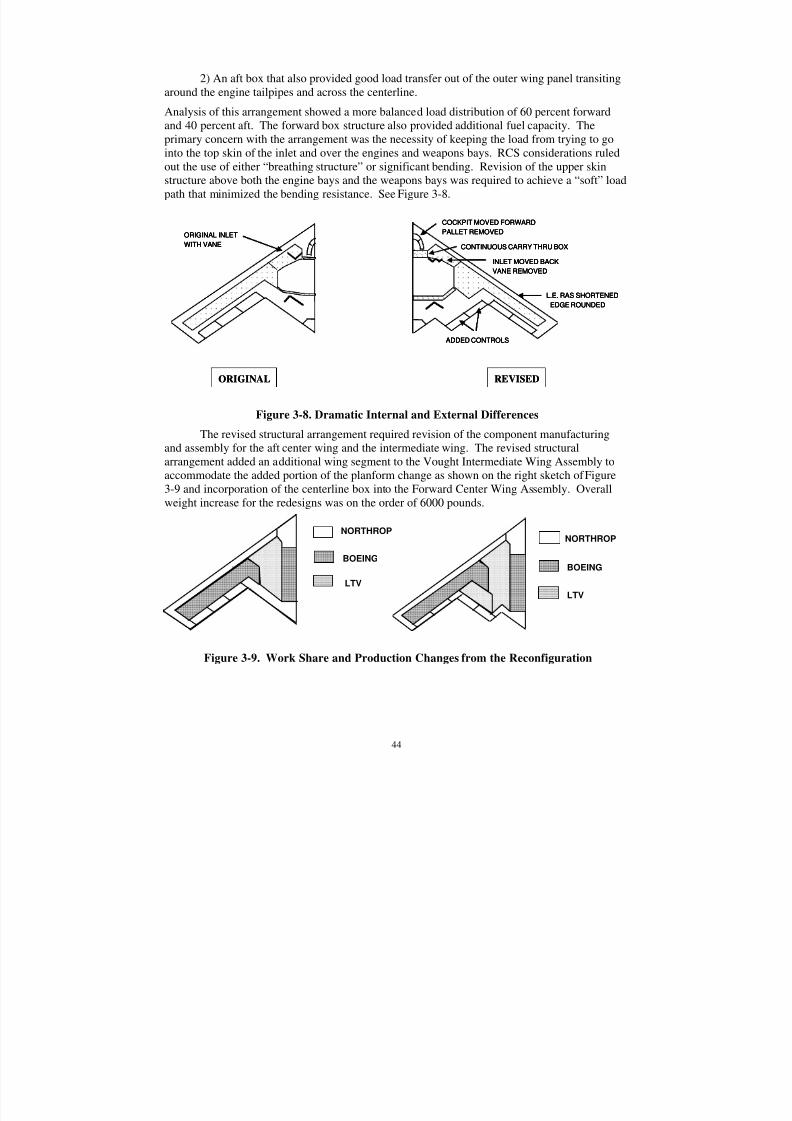
8/3/2019 B-2 Systems Engineering Case Studies
http://slidepdf.com/reader/full/b-2-systems-engineering-case-studies 58/118
44
2) An aft box that also provided good load transfer out of the outer wing panel transitingaround the engine tailpipes and across the centerline.
Analysis of this arrangement showed a more balanced load distribution of 60 percent forwardand 40 percent aft. The forward box structure also provided additional fuel capacity. Theprimary concern with the arrangement was the necessity of keeping the load from trying to go
into the top skin of the inlet and over the engines and weapons bays. RCS considerations ruledout the use of either “breathing structure” or significant bending. Revision of the upper skinstructure above both the engine bays and the weapons bays was required to achieve a “soft” loadpath that minimized the bending resistance. See Figure 3-8.
ORIGINAL REVISED
ORIGINAL INLET
WITH VANE
COCKPIT MOVED FORWARD
PALLET REMOVED
INLET MOVED BACK
VANE REMOVED
CONTINUOUS CARRY THRU BOX
ADDED CONTROLS
L.E. RAS SHORTENED
EDGE ROUNDED
ORIGINAL REVISED
ORIGINAL INLET
WITH VANE
ORIGINAL INLET
WITH VANE
COCKPIT MOVED FORWARD
PALLET REMOVED
INLET MOVED BACK
VANE REMOVED
CONTINUOUS CARRY THRU BOX
ADDED CONTROLS
L.E. RAS SHORTENED
EDGE ROUNDED
COCKPIT MOVED FORWARD
PALLET REMOVED
INLET MOVED BACK
VANE REMOVED
CONTINUOUS CARRY THRU BOX
ADDED CONTROLS
L.E. RAS SHORTENED
EDGE ROUNDED
Figure 3-8. Dramatic Internal and External Differences
The revised structural arrangement required revision of the component manufacturingand assembly for the aft center wing and the intermediate wing. The revised structuralarrangement added an additional wing segment to the Vought Intermediate Wing Assembly toaccommodate the added portion of the planform change as shown on the right sketch of Figure3-9 and incorporation of the centerline box into the Forward Center Wing Assembly. Overallweight increase for the redesigns was on the order of 6000 pounds.
NORTHROP
BOEING
LTV
NORTHROP
BOEING
LTV
Figure 3-9. Work Share and Production Changes from the Reconfiguration
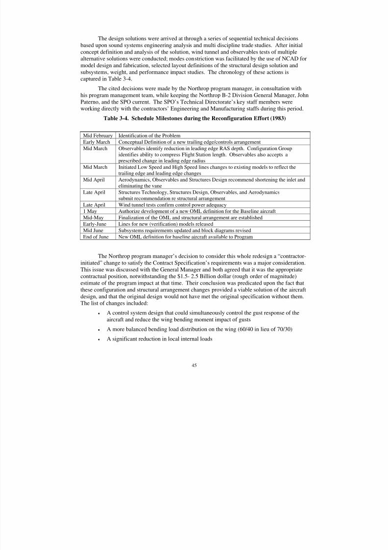
8/3/2019 B-2 Systems Engineering Case Studies
http://slidepdf.com/reader/full/b-2-systems-engineering-case-studies 59/118
45
The design solutions were arrived at through a series of sequential technical decisionsbased upon sound systems engineering analysis and multi discipline trade studies. After initialconcept definition and analysis of the solution, wind tunnel and observables tests of multiplealternative solutions were conducted; modes constriction was facilitated by the use of NCAD formodel design and fabrication, selected layout definitions of the structural design solution and
subsystems, weight, and performance impact studies. The chronology of these actions iscaptured in Table 3-4.
The cited decisions were made by the Northrop program manager, in consultation withhis program management team, while keeping the Northrop B-2 Division General Manager, JohnPaterno, and the SPO current. The SPO’s Technical Directorate’s key staff members wereworking directly with the contractors’ Engineering and Manufacturing staffs during this period.
Table 3-4. Schedule Milestones during the Reconfiguration Effort (1983)
The Northrop program manager’s decision to consider this whole redesign a “contractor-initiated” change to satisfy the Contract Specification’s requirements was a major consideration.This issue was discussed with the General Manager and both agreed that it was the appropriatecontractual position, notwithstanding the $1.5- 2.5 Billion dollar (rough order of magnitude)estimate of the program impact at that time. Their conclusion was predicated upon the fact thatthese configuration and structural arrangement changes provided a viable solution of the aircraft
design, and that the original design would not have met the original specification without them.The list of changes included:
• A control system design that could simultaneously control the gust response of theaircraft and reduce the wing bending moment impact of gusts
• A more balanced bending load distribution on the wing (60/40 in lieu of 70/30)
• A significant reduction in local internal loads
Mid February Identification of the Problem
Early March Conceptual Definition of a new trailing edge/controls arrangement
Mid March Observables identify reduction in leading edge RAS depth. Configuration Groupidentifies ability to compress Flight Station length. Observables also accepts aprescribed change in leading edge radius
Mid March Initiated Low Speed and High Speed lines changes to existing models to reflect thetrailing edge and leading edge changes
Mid April Aerodynamics, Observables and Structures Design recommend shortening the inlet andeliminating the vane
Late April Structures Technology, Structures Design, Observables, and Aerodynamicssubmit recommendation re structural arrangement
Late April Wind tunnel tests confirm control power adequacy1 May Authorize development of a new OML definition for the Baseline aircraft
Mid-May Finalization of the OML and structural arrangement are established
Early-June Lines for new (verification) models releasedMid June Subsystems requirements updated and block diagrams revised
End of June New OML definition for baseline aircraft available to Program
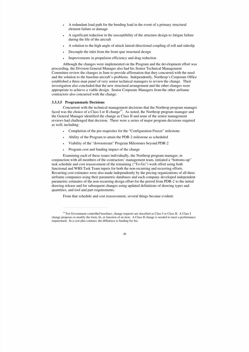
8/3/2019 B-2 Systems Engineering Case Studies
http://slidepdf.com/reader/full/b-2-systems-engineering-case-studies 60/118
46
• A redundant load path for the bending load in the event of a primary structuralelement failure or damage
• A significant reduction in the susceptibility of the structure design to fatigue failureduring the life of the aircraft
• A solution to the high angle of attack lateral-directional coupling of roll and sideslip
• Decouple the inlet from the front spar structural design
• Improvements in propulsion efficiency and drag reduction
Although the changes were implemented on the Program and the development effort wasproceeding, the Division General Manager also had his Senior Technical ManagementCommittee review the changes in June to provide affirmation that they concurred with the needand the solution to the baseline aircraft’s problems. Independently, Northrop’s Corporate Officeestablished a three-man panel of very senior technical managers to review the change. Theirinvestigation also concluded that the new structural arrangement and the other changes wereappropriate to achieve a viable design. Senior Corporate Managers from the other airframe
contractors also concurred with the change.
3.3.3.5 Programmatic Decisions
Concurrent with the technical management decisions that the Northrop program managerfaced was the choice of a Class I or II change
15. As noted, the Northrop program manager and
the General Manager identified the change as Class II and none of the senior managementreviews had challenged that decision. There were a series of major program decisions requiredas well, including:
• Completion of the pre-requisites for the “Configuration Freeze” milestone
• Ability of the Program to attain the PDR-2 milestone as scheduled
• Viability of the “downstream” Program Milestones beyond PDR-2
• Program cost and funding impact of the change
Examining each of these issues individually, the Northrop program manager, inconjunction with all members of the contractors’ management team, initiated a “bottoms-up”task schedule and cost reassessment of the remaining (“To-Go”) work effort using bothfunctional and WBS Task Team inputs for both the non-recurring and recurring efforts.Recurring cost estimates were also made independently by the pricing organizations of all threeairframe companies using their parametric databases and each company developed independentparametric estimates of the non-recurring design effort for the period from PDR-2 to the initialdrawing release and for subsequent changes using updated definitions of drawing types and
quantities, and tool and part requirements.From that schedule and cost reassessment, several things became evident:
15 For Government controlled baselines, change requests are classified as Class I or Class II. A Class Ichange proposes to modify the form, fit, or function of an item. A Class II change is needed to meet a performancerequirement. In a cost plus contract, the difference is funding for fee.
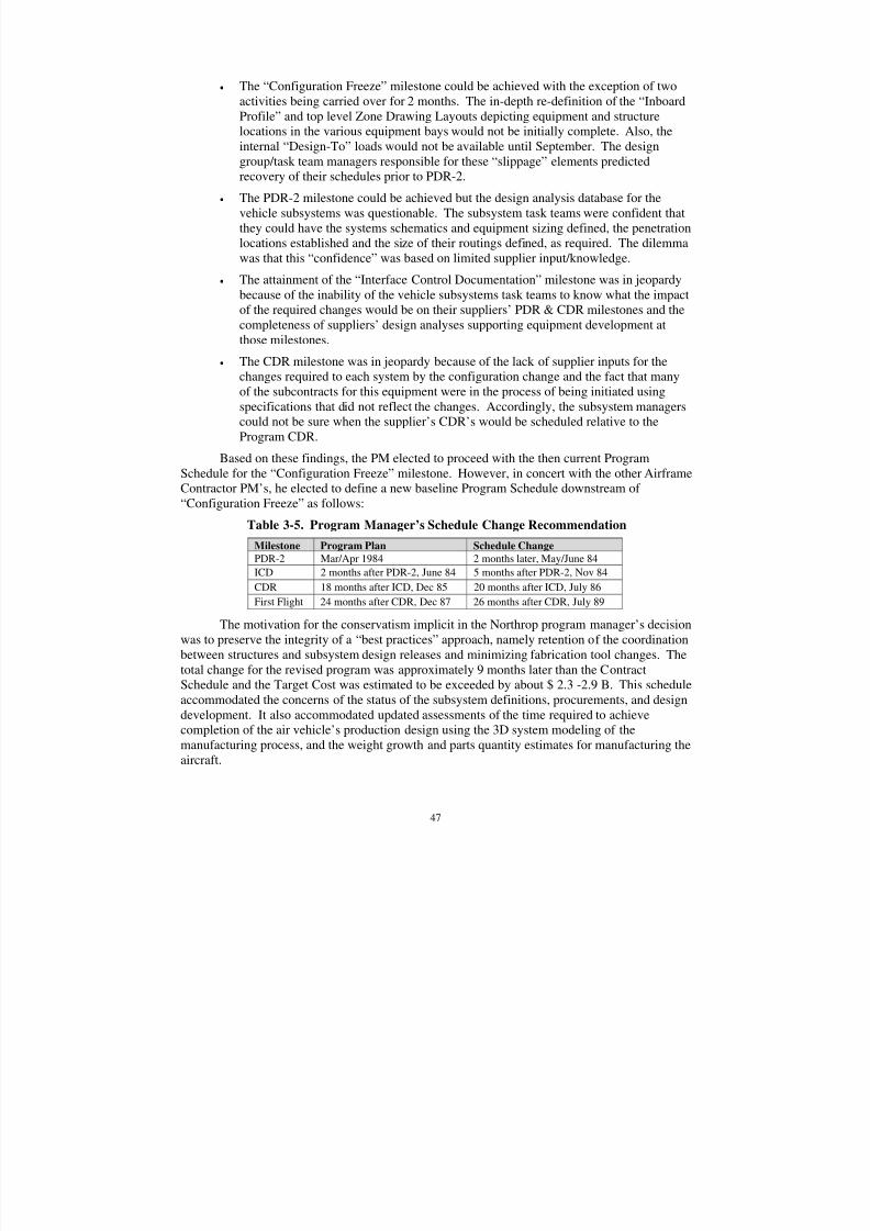
8/3/2019 B-2 Systems Engineering Case Studies
http://slidepdf.com/reader/full/b-2-systems-engineering-case-studies 61/118
47
• The “Configuration Freeze” milestone could be achieved with the exception of twoactivities being carried over for 2 months. The in-depth re-definition of the “InboardProfile” and top level Zone Drawing Layouts depicting equipment and structurelocations in the various equipment bays would not be initially complete. Also, theinternal “Design-To” loads would not be available until September. The design
group/task team managers responsible for these “slippage” elements predictedrecovery of their schedules prior to PDR-2.
• The PDR-2 milestone could be achieved but the design analysis database for thevehicle subsystems was questionable. The subsystem task teams were confident thatthey could have the systems schematics and equipment sizing defined, the penetrationlocations established and the size of their routings defined, as required. The dilemmawas that this “confidence” was based on limited supplier input/knowledge.
• The attainment of the “Interface Control Documentation” milestone was in jeopardybecause of the inability of the vehicle subsystems task teams to know what the impactof the required changes would be on their suppliers’ PDR & CDR milestones and thecompleteness of suppliers’ design analyses supporting equipment development atthose milestones.
• The CDR milestone was in jeopardy because of the lack of supplier inputs for thechanges required to each system by the configuration change and the fact that manyof the subcontracts for this equipment were in the process of being initiated usingspecifications that did not reflect the changes. Accordingly, the subsystem managerscould not be sure when the supplier’s CDR’s would be scheduled relative to theProgram CDR.
Based on these findings, the PM elected to proceed with the then current ProgramSchedule for the “Configuration Freeze” milestone. However, in concert with the other AirframeContractor PM’s, he elected to define a new baseline Program Schedule downstream of
“Configuration Freeze” as follows:
Table 3-5. Program Manager’s Schedule Change Recommendation
Milestone Program Plan Schedule Change PDR-2 Mar/Apr 1984 2 months later, May/June 84
ICD 2 months after PDR-2, June 84 5 months after PDR-2, Nov 84
CDR 18 months after ICD, Dec 85 20 months after ICD, July 86
First Flight 24 months after CDR, Dec 87 26 months after CDR, July 89
The motivation for the conservatism implicit in the Northrop program manager’s decisionwas to preserve the integrity of a “best practices” approach, namely retention of the coordinationbetween structures and subsystem design releases and minimizing fabrication tool changes. The
total change for the revised program was approximately 9 months later than the ContractSchedule and the Target Cost was estimated to be exceeded by about $ 2.3 -2.9 B. This scheduleaccommodated the concerns of the status of the subsystem definitions, procurements, and designdevelopment. It also accommodated updated assessments of the time required to achievecompletion of the air vehicle’s production design using the 3D system modeling of themanufacturing process, and the weight growth and parts quantity estimates for manufacturing theaircraft.
8/3/2019 B-2 Systems Engineering Case Studies
http://slidepdf.com/reader/full/b-2-systems-engineering-case-studies 62/118
48
After development of this plan, and following discussions with the GM, the SPODirector, and the senior Technical Advisory Committee, alternative schedule components wereidentified for management consideration. Essentially these alternative plans examined ways tooffset or minimize the schedule and cost growth issues of the PM’s plan by the following:
• Reduce the manufacturing schedule by eliminating “stuffing” of major assemblies
(i.e. installation of all equipment and system routings) prior to shipment to the FinalAssembly facility. This would save 2-3 months of schedule but add costs forrelocation and per diem expenses of the traveled work force plus loss of efficiency.
• Hold the PDR-2 and CDR milestones where originally planned with the provisionthat if the subsystem design was not mature at the planned CDR milestone, potentialalternatives to the downstream Program Plan would be reviewed. This would save 4months of schedule time but required the addition of a cost contingency for aschedule slide at CDR
• Hold the ICD milestone in July 1984 in lieu of September 1984. This would save 2months but require added contingency for rework of “production released” ICD’s and
the expected resultant design changes.• Reduce the historical “change factor” used in engineering and manufacturing
estimates because of the use of a 3D database.
• Use the original estimating factor for production design drawing development andincrease the estimate only for the increased drawing quantity estimate.
The development of these alternatives was completed in time for the September 1983quarterly CEO/Commander meeting scheduled at WPAFB, OH. Initially the review focused onthe configuration changes, the rationale for each, and the new projected system performance.The alternative plans’ assumptions and input variations were reviewed. There was acceptancethat schedule slippage might occur, but it was believed that maintaining the original schedule
would provide the lowest overall cost and shortest time to first flight. The selected plan had aprojected cost impact of approximately $1.5 -2.0 B. The subcontractor program managers wereencouraged to use their “best efforts” to hold the Contract Program Schedule
3.3.4 Preliminary Design Review (PDR-2)
Following the resolution of the Contract Plan, the Program proceeded to close all theremaining technical and producibility risks required to support PDR-2 except for the RadarAntenna performance demonstration. PDR-2 was successfully conducted in the March/April1984 period with all requirements satisfied. Test data from the low speed and high-speedverification wind tunnel tests and from verification tests on a new, large-scale observables modelof the aircraft demonstrated compliance with the contract specification. At PDR-2, the SPO
added a requirement for Reliability Design Growth Testing (RDGT) so that all weapon systemelements would achieve significant system reliability maturity by IOC.
The radar antenna design failure that occurred during the risk reduction phase had beendiagnosed and the contractor (Hughes) had initiated a series of risk closure activities, which werepresented at PDR-2. At the completion of those closure activities (August’84), the antennaperformance and its observables characteristics were demonstrated in compliance with thecontractor team’s PDR-2 commitment.
8/3/2019 B-2 Systems Engineering Case Studies
http://slidepdf.com/reader/full/b-2-systems-engineering-case-studies 63/118
49
Although the subsystems’ WBS Task Teams were able to meet the requirements forPDR-2, the desired depth of analyses and vendor design development supporting the designdefinitions was not achieved. This became evident when the contractor team attempted to meetits next Program milestone.
3.3.5 Interface Control Document (ICD) Closure Date
This milestone was originally scheduled for June 1984, but was not completed on time.It took approximately two additional months to satisfy the criteria for this event. The majordeficiency was the lack of specific data for the vehicle subsystems caused by the changes tothose systems necessitated by the reconfiguration. The implementation of these changes wasimpacted by the need for substantive subcontract changes, even though letter contract authoritywas utilized. The difficulty was the need for specification revisions which required supplierengineering’s analyses before making commitments on price.
3.3.6 Critical Design Review (CDR)
The B-2 Critical Design Review was held per the Contract Schedule (December 1985).The structure design completion goal of 90% drawing release was met but the subsystems design
release was only 20% complete versus a goal of 90%. Action plans to address these shortfallswere generated and incorporated as part of the CDR closure. No change in contract schedulewas made as a result of the action plans but there was tacit acceptance by the SPO programmanager of the Northrop program manager’s decision to revise the Program’s internal work plan/schedule whereby a one year delay in first flight was defined (i.e. December 1988 in lieu of December 1987).
To partially offset the Vehicle Subsystems design definition shortfall and the 12-15months delay that the Program was then projecting, the Northrop program manager elected toinitiate a change to the work plan whereby the major assembly stuffing would be deferred toaircraft final assembly. This action reduced the delay by approximately 2-3 months resulting in
the projected flight date of March 1988. The actual accomplishment of the 100% release pointtook about five months. Not all of that delay affected the build of A/V #1 but it did impact theavailability of production hardware for qualification testing, conduct of complete system tests inthe various laboratories, and the reliability growth test program.
Leading up to this critical review, the preparations were initiated in the early summer of 1985. There were indications at this time that the subsystems were lagging in progress to theirentry criteria for the review. Numerous discussions were conducted within the SPO and with thecontractor concerning CDR preparation and our readiness to conduct the review. The SPO chief systems engineer, Tim Sweeney, reported to the principles that all of the criteria were not yetsatisfied. The SPO principals finally concluded that the CDR would be held on the stipulateddate and coordinated the decision with the contractor principles. The conclusion that the
structure was sufficiently mature was a key consideration, with the objective of conducting theCDR and holding open action items for those items not completed to the criteria. This wasconsistent with the decision that was made after PDR 2 at the program CEO meeting in the fallof 1983. At this meeting between the company CEOs, the Air Force senior general officer atAeronautical Systems Division, and their program managers, it was agreed that relieving theschedule would remove the pressure from the team and would increase the risk of an even furtherschedule slip than was being projected. CDR was held in October and November 1985, with thefinal wrap-up held on December 5, 1985.
8/3/2019 B-2 Systems Engineering Case Studies
http://slidepdf.com/reader/full/b-2-systems-engineering-case-studies 64/118
50
At the conclusion of the CDR the entire team recognized that the schedule was indeed in jeopardy and that first flight in December 1987 was at risk. The program debated the wisdom tore-baseline a new schedule, construct a new target baseline and develop a new over target cost(OTC) profile. The majority of the decision-makers concurred in maintaining the currentprogram schedule and delaying the construction of an over target baseline until there was
sufficient maturity to define a new schedule with high confidence.3.4 System Checkout/First Flight
The first flight event was scheduled to occur in December of 1987 as an original contractmilestone. As a result of the reconfiguration, the Northrop program office had assessed at CDRthat this milestone would occur in December 1988. The actual flight date was 6 months later(July 1989). The Northrop program manager made the decision to set the schedule down by 12months by deciding to incur the additional costs associated with the two airframe subcontractorsand Northrop’s Pico Rivera facility relocating their subsystems installation work force andsupport organizations to the final assembly facility for what was anticipated to be A/V #1 – #3.As envisioned, the additive costs were essentially the per diem costs for that work force for 6months. The reality was that the time actually extended until A/V #7 due to the level of changeactivity and other unforeseen events not related to the configuration change. Major contributorsto the further delay; were the inefficiencies in stuffing the first aircraft, delayed completion of theelectrical system installation/check-out, the time required to perform the functional systemcheck-out the first time on a very complex aircraft system, and the re-assessment by theCombined Test Force (CTF) of A/V #1’s maiden pre-flight test requirements.
8/3/2019 B-2 Systems Engineering Case Studies
http://slidepdf.com/reader/full/b-2-systems-engineering-case-studies 65/118
51
4.0 SUMMARY
The story of the B-2 engineering development is rich with the trials and tribulations of avery complex aeronautical system. In order to scope this case study, the authors determinedthere were five top Learning Principles for the B-2 program.
LP 1, Integration of the Requirements and Design Process: A key aspect of the
implementation of the B-2 systems engineering process was the integration of the SPO
requirement’s team with the contractors’ design team, including manufacturing, Quality
Assurance, and logistics functionals into a cohesive program effort. This facilitated continual
trade studies conducted by the specialists from the User/SPO government team with the company
specialists to fully assess the performance trade-offs against schedule, cost, and risk.
The systems engineering process of the B-2 development program was systemic to thedesign process and the engineers, manufacturing, Quality Assurance, logisticians, and programspecialists from the customer, User, and contractors all participated as equals. Everyonecontributed to the development of the requirements and the evolution of the design. When arequirement was causing a design risk that would manifest itself as a cost, schedule, or
performance impact, the team would construct alternative approaches, the SPO members wouldassess the change to performance with the User to evaluate the necessity to achieve fullcompliance or rebalance capability. Cost and schedule alternatives would be developed. Manytimes, the problems could be resolved within the teams or traded within interfacing capabilities.The day-to-day involvement with the technical specialists kept the team ready to make rapidassessments.
It is vital to control the specifications at the proper time. While the combined teamdeveloped the specification, it is the role of the customer to own and control the specifications,but to be ever vigilant for cases where the requirements become difficult to meet. In this case, itis the final decision of the customer to either fund the effort to meet the specification or changeit. This was particularly true for the specifications that were not part of the initial contract. The
specifications that were prepared by PDR 1 for the SPO were all reviewed for changes in scope.But, it was always part of the strategy and the program funding to baseline these specifications aspart of PDR 1. PDR 1 was different from a Systems Requirements Review (SRR) where therequirements are typically reviewed across the entire system. Rather, this review developed thesubsystem specifications as derived from the top level specifications, which were approved andcontrolled at the contract signing. The strategy to require the system, air vehicle, engine andtraining specifications at contract award, the performance based subsystems specifications atPDR 2, and the detailed design specifications at Product Verification Review was a factor to thesuccess of the systems engineering process within the program. This was even true for the RCSspecification addendum to the Weapon System specification, which was placed on contract as ano cost change.
Beside the obvious lesson learned from the efficiencies gleaned from the combinedefforts of the specialists and the overall program philosophy of cooperation, there is a subtle, butimportant point that must be highlighted to caution the practitioner of the potential pitfalls of thisstrategy. After the CDR milestone, it is vital to control this working relationship. The effortfrom CDR to first flight is centered on manufacturing the parts, assembling the aircraft,qualifying the components, and checking out the assembled system. This is simply hard work,and any unnecessary or superfluous change is an enormous and unwanted burden on an already
8/3/2019 B-2 Systems Engineering Case Studies
http://slidepdf.com/reader/full/b-2-systems-engineering-case-studies 66/118
52
burdensome time frame. Since the WBS Task Teams worked so closely and had implementedthe design in conjunction with the Using command, and since there is always a “better” way toimplement some of the features of the design, there is a constant pressure at the working level tomake enhancements. In order to control this culture after the CDR, all the Using commandofficers were only participants in formal Technical Interchange Meetings (TIM), and all TIMs
were mandated to have minutes prepared, signed by the contractor responsible engineer (RE),cosigned by the SPO counterpart, and have an action item list for approval at the Chief Engineerlevel. The engineering leadership continuously stressed the necessity to control changes andmake only “must have to work” or safety related changes.
LP 2, WBS Task Teams and Functional Hierarchy: The contract Work Breakdown
Structure (WBS) stipulated the entire program content and tasking and the company organized
the development effort into WBS teams responsible to implement the contract WBS. These WBS
Task Teams were assigned complete work packages - for example, the forward center wing. The
systems engineering WBS Task Team efforts were organized similarly, but with separate
responsibilities, each reporting to the Northrop chief engineer or his deputies. The functional
organizations assigned members to the task teams to assure accommodation of their program
needs. A vital distinction from many of today’s IPTs was retaining the WBS Task Teammembership throughout the functional organizations’ various management levels. This
facilitated communication, integration, interfaces, and integrated the functional leadership of
each of the company’s technical and management disciplines into the decision process. The
program management top-level structure was organized into a strong project office with
centralized decision authority and strong leadership at the top of both the SPO and the
contractor organizations.
The WBS task team construct was unusual because it had the inherent checks to mitigateagainst the tendency to become independent. Since the WBS task team leader did not own theassets, the members had a responsibility to their functional organization to report and seek guidance. The functional leadership instilled a balancing factor in decisions. The functionalleadership was forced to provide assistance to the project managers, who had the mandate todeliver products. A strong centralized program management/leadership role was crucial toprovide the guidance and focus for each company and for the integrated program. The processcould quickly surface the problem to the appropriate decision level and the program wouldefficiently reach a consensus and resolve the issue. Awareness, knowledge, experience,consistency in the work force, and the authority to act were ingrained in the participants.
One particularly important and very illustrative event that underscores the effectivenessof the WBS Task Team effectiveness was a decision made early-on that would have profoundand positive impact on the program 6 years later. The Air Vehicle systems engineering groupidentified a manufacturing risk (well prior to PDR 1) for the potential difficulty of mating the
various wing sections during final assembly. Working in concert with the ManufacturingEngineering and Tool Design Groups, the joint SPO/contractor team developed a plan to reducethat risk (and in the case of Air Vehicle #2 save the aircraft assembly’s compliance with thespecification) by designing a special mating tool for both the Intermediate Wing to aft centerwing/forward center wing, and the Outboard Wing to Intermediate Wing. This machineimplemented precise, computer-controlled, micro adjustments with 6 Degrees-of-Freedom(DOF) of each of the major assemblies during the mating operation.
8/3/2019 B-2 Systems Engineering Case Studies
http://slidepdf.com/reader/full/b-2-systems-engineering-case-studies 67/118
53
LP 3, Air Vehicle Reconfiguration: The identification of a major aeronautical control
inadequacy of the baseline configuration just four months prior to the formal Configuration
Freeze milestone caused an immediate refocus of the Task Teams to develop a substantially
revised design. Within several days, the air vehicle task teams were conducting trade studies,
augmenting their skill sets, and integrating with the other program participants in a coordinated
effort to derive an efficient, controllable, operationally useful system. At the same time, the program elements that were not markedly affected by the change maintained a course that
preserved their schedule, but was sufficiently flexible to include any potential changes. In a
program wide systems engineering effort, the prime contractor’s program office integrated the
teams, reviewed their efforts, coordinated the systems trades, and identified significant changes
to the outer mold lines, the radar cross section (RCS) baseline, all major structure assemblies,
and all major air vehicle subsystems requirements, with the exception of avionics and armament.
The alternatives were derived by the end of the third month, the final choice was selected by the
sixth month, and the seventh month was used to coordinate and garner the approval of all
stakeholders. While the program response to the crisis was rapid and effective, and a significant
impact on the downstream cost and schedule was anticipated by the management team, and the
technical impact was predicted by the systems engineering process, it was not predicted to the fullest extent.
By the time the student has reached this point in the case study, it should be clear that thetrue underlying principle of LP3 is the necessity to stop all the baseline effort when a problem of this magnitude arises and concentrate all efforts on finding a solution. The program did thiswell. The people who knew there was a problem had the ability to go to the appropriate decisionlevel, the program manager accepted the bad news professionally, the teams put in place animmediate recovery plan, the program responded quickly, and the new plan was developed andimplemented. This can also be parsed to a lower level, even to the subsystems and componentlevel.
LP 4, Subsystem Maturity: The effect of the reconfiguration on the maturity of all the
air vehicle subsystems (flight control, environmental control, electrical, landing gear, etc) was
far greater than projected. The subsystems were mostly vendor-supplied equipments and some
were in the selection process to the technical requirements of the original baseline when the
reconfiguration occurred. After the new configuration was derived, the requirements for the
subsystems changed to such a degree that they had to be resized and repackaged. It took longer
than anticipated by the systems engineering process to recognize the growing problem of getting
all the specifications updated and to identify the lagging equipment maturity that resulted. Thus,
the reconfiguration required a second iteration of the design requirements and their flow-down
to the many suppliers and their detailed designs. These iterations after PDR-2 resulted in the
vehicle subsystems not achieving their Critical Design Review (CDR) milestone concurrently
with the structure, but rather five months later.
As in LP3, where the program concentrated in developing a new plan, here, the programalso constituted a new plan but it did not have the complete design and installation impact. Theprogram had several options such as moving CDR or analyzing the subsystems to determinewhat additional resources it would have taken to meet the original date for CDR with a newbaseline.
The configuration change had a major impact on the Program’s conduct in all aspects-technical, schedule, and cost. The technical impacts went beyond the late completion of the
8/3/2019 B-2 Systems Engineering Case Studies
http://slidepdf.com/reader/full/b-2-systems-engineering-case-studies 68/118
54
structure and subsystems design. The subsystem design delays necessitated a higher level of structural changes. This necessitated retention of more structural design staff on the program fora longer period. The execution of the subsystems development on a compressed basis (eventhough not attained) necessitated a significantly larger staff for a longer period. These sameimpacts existed at each of the major airframe locations. In addition, the majority of the
subsystem suppliers were pressed into significant overtime usage in attempts to complete theirdesign and build of early pre-production units to support system level verification and validationtests. The lateness of the subsystems’ definitions had its maximum cumulative effect on thefinalization of the electrical circuitry design which impacted the initial build of wire harnessesand the completion and checkout of the aircraft. Both of these issues became problems in theirown right in final assembly. The relocated subsystem installation teams at the final assemblyfacility were less efficient due to aircraft access, schedule “work-a-rounds,” the long supplychain from their “home” facility, and iterative design changes.
LP 5, Risk Planning and Management: The program was structured so that all risks
affecting the viability of the weapons system concept were identified at contract award and were
structured as part of the Program and WBS work plans. The initial risks were comprised of
those “normal” risks associated with a large complex weapons system development, as well asthe new technology and processes necessary to mature the program to low to medium risk at
PDR. Those initial risks were closed prior to PDR 2. The risk closure process continued
throughout development and identified new risks and continuously identified new risk closure
plans. Most importantly, the work associated with risk closure for each plan was integrated into
the WBS task teams’ work plans and into the Program Plans. These detailed plans showed all
design, analyses, tests, tooling, and other tasks necessary to close the identified risks and were
maintained and reviewed as part of the normal design/program reporting activity. The program’s use of a disciplined, decentralized risk management program was a major
contributor to developing an integrated, funded, resourced plan. It helped drive everyone to seek the right solution in the most efficient manner. Treating Risk Management as a discipline with adefinitive process and locating it at the level where work was accomplished was a major successstory. Everyone participated; the lowest level of the design team was responsible for closure,status, and reporting. All the resources necessary to close the risk were incorporated in theWBS, including the basic plan and all the alternatives, if required. The Risk Closure Plans werereviewed at quarterly program management reviews (QPMR) and the leader of the WBS task team had to get the agreement of all the participants from all the sides of the program before itcould be presented to the program management team. This forced a major systemsintegration/systems engineering activity to assure agreement before the results, recommendation,and alternatives were presented.
Thus, the concept for risk planning was unique in that the approach was predicated upon
logic rather than procedures. It required all functions to identify their primary risk issues (relatedto the product or the processes to develop the product), develop the logic trail of data anddecision points for resolving those issues, identify the associated activities for that resolution andonly then develop the appropriate work plan, schedule, and costs for accomplishing thoseactivities and the remainder of their functional/discipline work plan. In some cases, the risk closure issues were of such high risk that “dual parallel paths” were developed for their closure.

8/3/2019 B-2 Systems Engineering Case Studies
http://slidepdf.com/reader/full/b-2-systems-engineering-case-studies 69/118
55
5.0 REFERENCES
1. Official Photographs by USAF of a B-2, back side drawing, 1996 and official charts from theAir Force B-2 Systems Program Office, Wright Patterson Air Force Base.
2. George Friedman and Andrew P. Sage, Case Studies of Systems Engineering and Management in Systems Engineering (advance copy), University of Southern California, CAand George Mason University, VA, 22 September 2003.
3. Griffin, J.M, Personal Interviews and editorial reviews of the first version, June 2004 toFebruary 2006, see Appendix 3.
4. DoD Architectural Framework, Version 1.0, 9 Feb 2004.
5. David Aronstein, Albert Piccirillo, Have Blue and the F-117A: Evolution of the “Stealth
Fighter”, AIAA, Reston, VA, 1997.
6. Northrop Grumman B-2 Case Study, Propriety.
8/3/2019 B-2 Systems Engineering Case Studies
http://slidepdf.com/reader/full/b-2-systems-engineering-case-studies 70/118
56
EDITOR’S NOTE Having been involved in the writing, editing and review of five Systems Engineering case
studies, I must remind the reader of scope and viewpoint. Time and money force themanagement of these cases to reflect upon only a few (4-6) key points which the authors deemmost important. Many, many more interesting vignettes could have filled out the entire
Freidman-Sage Matrix for a program the size of the B-2. While the authors often foundthemselves on a historical quest for more (more information, documentation, interviews andconfirmations), I was forced to continually scope the writing effort to completion.
The authors and those interviewed often may disagree on the top learning principles.Clearly author viewpoint and unintentional bias may find its way onto these pages. I have madeall attempts to remove unnecessary or overtly biased statements. Every additional review of pastcases would uncover disparate viewpoints and recollections of facts and/or decisions made onthose facts. It was my belief that having co-authors on this B-2 case, one from the governmentand one from the prime contractor, would instill an overall balanced perspective in the finaldocument.
Lastly, I hope that reading the AF CSE cases, together with other case study materials,will allow practitioners and Systems Engineering students alike to be thoughtful of the lessonslearned across the nine concept areas and three responsibility areas of the F-S framework. Eachprogram has unique technical, political, and managerial characteristics, so the lessons first needto be understood in the unique, historical context, but can often be generalized and rationalizedfor current environments.
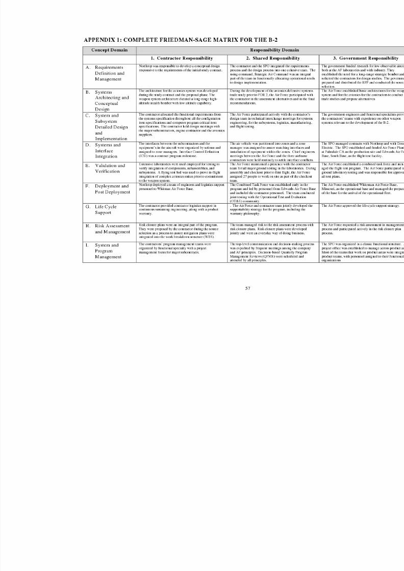
8/3/2019 B-2 Systems Engineering Case Studies
http://slidepdf.com/reader/full/b-2-systems-engineering-case-studies 71/118
8/3/2019 B-2 Systems Engineering Case Studies
http://slidepdf.com/reader/full/b-2-systems-engineering-case-studies 72/118
58
APPENDIX 2: AUTHOR BIOGRAPHIES
JOHN M. GRIFFIN
John Griffin is President, Griffin Consulting, providing systems engineering and program
management services to large and mid sized aerospace firms. He provides corporate strategyplanning initiatives for company CEOs, reviews ongoing programs to assess progress andrecommend corrective actions, and participates as an integral member of problem solving teams.He is active in numerous leading-edge technologies and advanced system developmentprograms.
Experience/Employment Highlights:
• Director of Engineering, Kelly Space and Technology, Inc, San Bernardino, CAConceptual design process of a space launch platform
• Director, Development Planning, Aeronautical Systems Center, Wright-PattersonAir Force Base, OH
• Chief Systems Engineer, Engineering Directorate
• Director of Engineering, B-2 Spirit Stealth Bomber, B-2 System Program OfficeEngineering leadership /and management from inception through 1st flight
• Source Selection Authority for two source selections
• Chief engineer, F-15 Eagle
• Chief Airframe Engineer, F-16 Fighting Falcon
• Chief Airframe Engineer, Air Launched Cruise Missile
Honors/Awards:
• Two Meritorious Service Medals
• Distinguished Career Service Medal for his 37 years of achievement, 1997
• Pioneer of Stealth, 1998
• University of Detroit Mercy; Engineering Alumnus of the Year, 2002
Education:
• University of Detroit, Detroit MI, 1964: Bachelor of Aeronautical Engineering
• Air Force Institute of Technology, WPAFB OH, 1968: MS of EE
•
Massachusetts Institute of Technology, Cambridge MA, 1986: Senior ExecutiveSloan Program
Affiliations:
• Founder (1993) and President (1993–1997), Western Ohio Chapter SeniorExecutive Association.
• Co-founder (1995) and President (1996–1997), Defense Planning and AnalysisSociety.
8/3/2019 B-2 Systems Engineering Case Studies
http://slidepdf.com/reader/full/b-2-systems-engineering-case-studies 73/118
59
JAMES A. KINNU
Mr. Kinnu is a retired Vice President of the Northrop Grumman Corporation, consultingto the Aerospace and Defense Electronics industries and certain U.S. Government agencies. Heled the Northrop Grumman Corporation’s successful Advanced Technology Bomber (B-2)proposal team and development efforts on the B-2 from September 1980 through 1988.
Experience/Employment History:
• United States Army, 1953 – 1955
• Lockheed Corporation, 1955 – 1971
Design Engineer and Project Engineering for the Electra Project
Contracts Manager for Commercial Aircraft
Advanced Systems Marketing Representative
Program Manager, Advanced Fighters
Program Manager, L-1011 Wing & Empennage
• Rockwell International Corporation, 1971 – 1977
Business Area Manager, Advanced Programs
Program Manager, Quiet STOL (QUESTOL)
Program Manager, Highly Maneuverable Aircraft Technology (HIMAT)
• Falcon Jet Corporation, Vice President and Assistant to the President, 1978
Modification & Overhaul Center, Teterboro, NJ
U. S. Coast Guard’s Falcon 20 Development Program, Little Rock, AK
• Northrop Corporation, 1979 -1992Staff Engineer, Advanced Systems
Manager, Advanced Design
Manager, Advanced Systems & Long Range Planning
Proposal Manager, Advanced Technology Bomber (ATB)
Vice President & Program Manager, B-2 Full Scale EngineeringDevelopment (FSED) Program
Corporate Vice President for Programs
Deputy General Manager, Aircraft DivisionCorporate Vice President for Programs
• Management Consultant, 1992 - 1995
Hewlett Packard Inc., Northrop Grumman Corp., Visionaire Corp.
McDonnell Douglas Corp., Bombardier Corp. – Short Brothers Division,Andersen Consulting Inc. and Aerospace/ Defense Electronics clients

8/3/2019 B-2 Systems Engineering Case Studies
http://slidepdf.com/reader/full/b-2-systems-engineering-case-studies 74/118
60
• Varilite International Inc., 1995-1997
Chief Operating Officer and Board of Directors Member
• U. S. Department of Justice, Expert Witness for A-12 Litigation, 1998 - present
• Northrop Grumman Corporation, Management Consultant, 2004 – present
Integrated Systems Sector
Education:
• University of California , Los Angeles, CA 1953: Bachelor of Science
Majors: Physics & Business Administration
Honors/Awards:
• U.S. Army Commendation Ribbon w/ Medal Pendant, 1955
• NASA, Aircraft Design Award for B-2 Aircraft, 1989
• Patent Award, Patent No. Design 314,366 (B-2 Aircraft), 1991
• AIAA Associate Fellow, 1991
8/3/2019 B-2 Systems Engineering Case Studies
http://slidepdf.com/reader/full/b-2-systems-engineering-case-studies 75/118
61
APPENDIX 3: INTERVIEWS
The company affiliation and positions are those held on the B-2 during the timeframe of the casestudy. Alphabetical list of interviews include:
James Bottemely, Lt. Col., Manufacturing Director, B-2 SPO
Dave Conklin, Northrop, Avionics Manager
Llewellyn “Doc” Dougherty, Lt. Col. Deputy SPO Chief Engineer
George Freidman, Northrop, Avionics and Chief Technical Officer
Joseph Keith Glenn, Colonel, Air Force, Program Manager
Tom Griskey, Northrop, Systems Engineering
Chris Hernandez, Northrop, System Engineer
Tom Marsh, General, AFSC Commander
Al Meyers, Northrop, Flight Control Manager
Stanley Richey, Air Force, Financial Manager
Richard Scofield, Brigadier General, Air Force, Program Manager
Lawrence Skantze, General, Air Force, Source Selection Advisory Board Chairman
Erich Smith, Vought, Test Engineer, Systems Engineer, Chief engineer
Henry Spence, Vought, Chief Engineer
James Sunkes, Air Force, Survivability Engineer
Tim Sweeney, Air Force, Chief Systems Engineer
Irv Waaland, Northrop, Chief Engineer
Mark Wilson, Air Force, Lead Structures Engineer
Howard Wood, Air Force, Structures engineer
Reviewers of the first draft version:
John Cashen, Northrop Weapons Systems Engineering Chief
(and patent holder with Kinnu and Waaland)
James Mattice, Wright Laboratory, ManTech Director
Robert Patton, Vought Program managerMark Wilson, Air Force Center for Systems Engineering
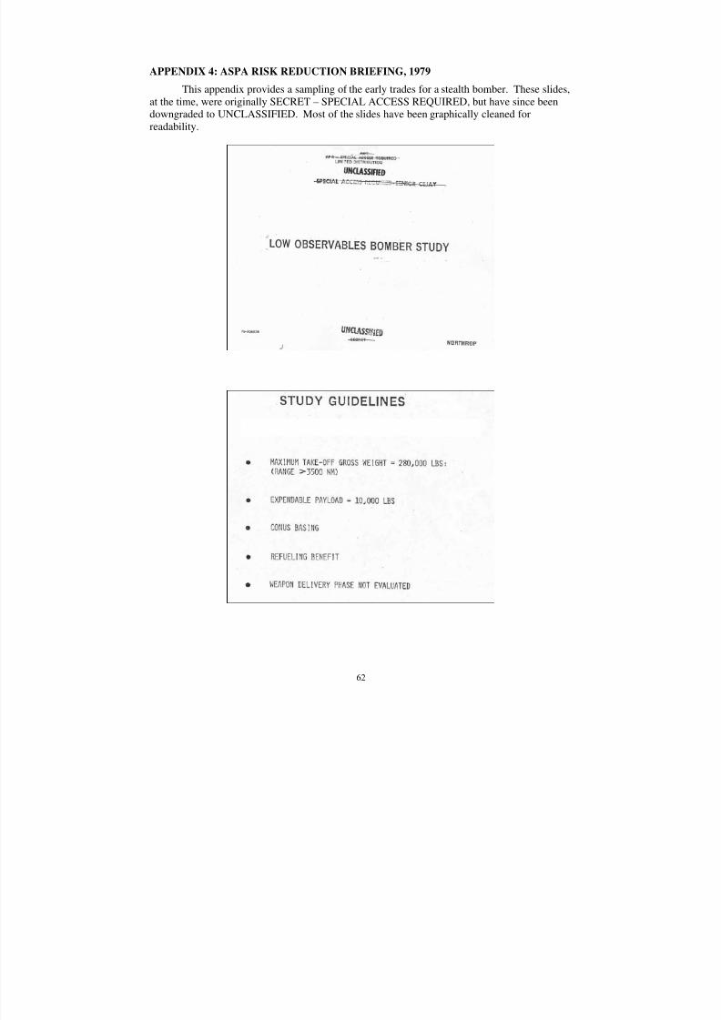
8/3/2019 B-2 Systems Engineering Case Studies
http://slidepdf.com/reader/full/b-2-systems-engineering-case-studies 76/118
62
APPENDIX 4: ASPA RISK REDUCTION BRIEFING, 1979
This appendix provides a sampling of the early trades for a stealth bomber. These slides,at the time, were originally SECRET – SPECIAL ACCESS REQUIRED, but have since beendowngraded to UNCLASSIFIED. Most of the slides have been graphically cleaned forreadability.
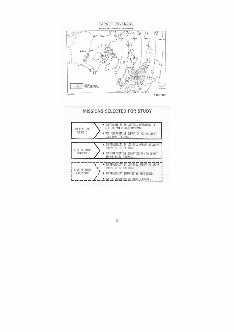
8/3/2019 B-2 Systems Engineering Case Studies
http://slidepdf.com/reader/full/b-2-systems-engineering-case-studies 77/118
63
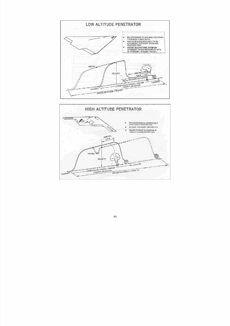
8/3/2019 B-2 Systems Engineering Case Studies
http://slidepdf.com/reader/full/b-2-systems-engineering-case-studies 78/118
64
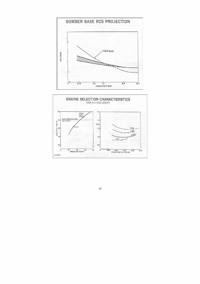
8/3/2019 B-2 Systems Engineering Case Studies
http://slidepdf.com/reader/full/b-2-systems-engineering-case-studies 79/118
65
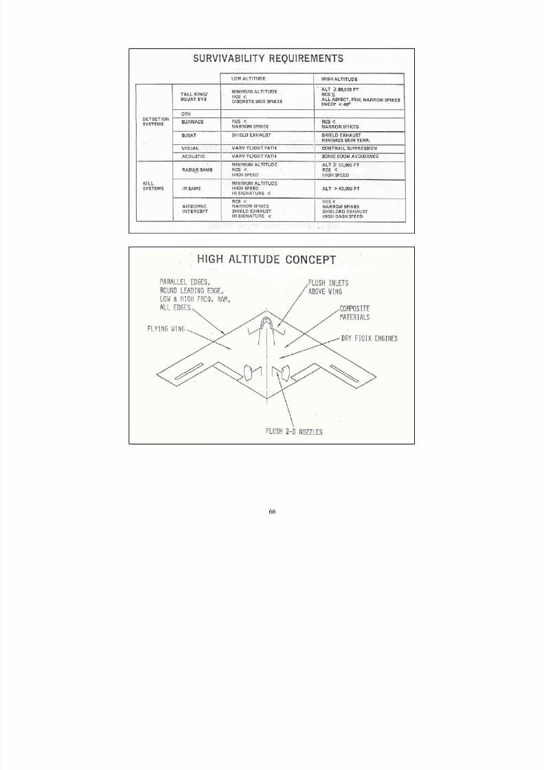
8/3/2019 B-2 Systems Engineering Case Studies
http://slidepdf.com/reader/full/b-2-systems-engineering-case-studies 80/118
66
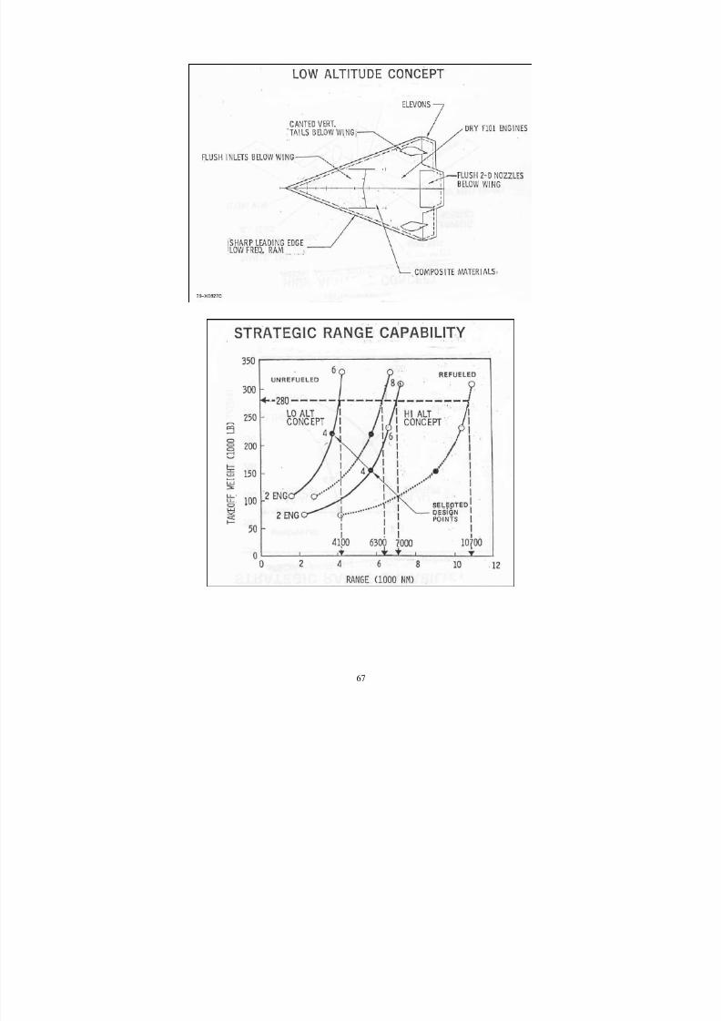
8/3/2019 B-2 Systems Engineering Case Studies
http://slidepdf.com/reader/full/b-2-systems-engineering-case-studies 81/118
67
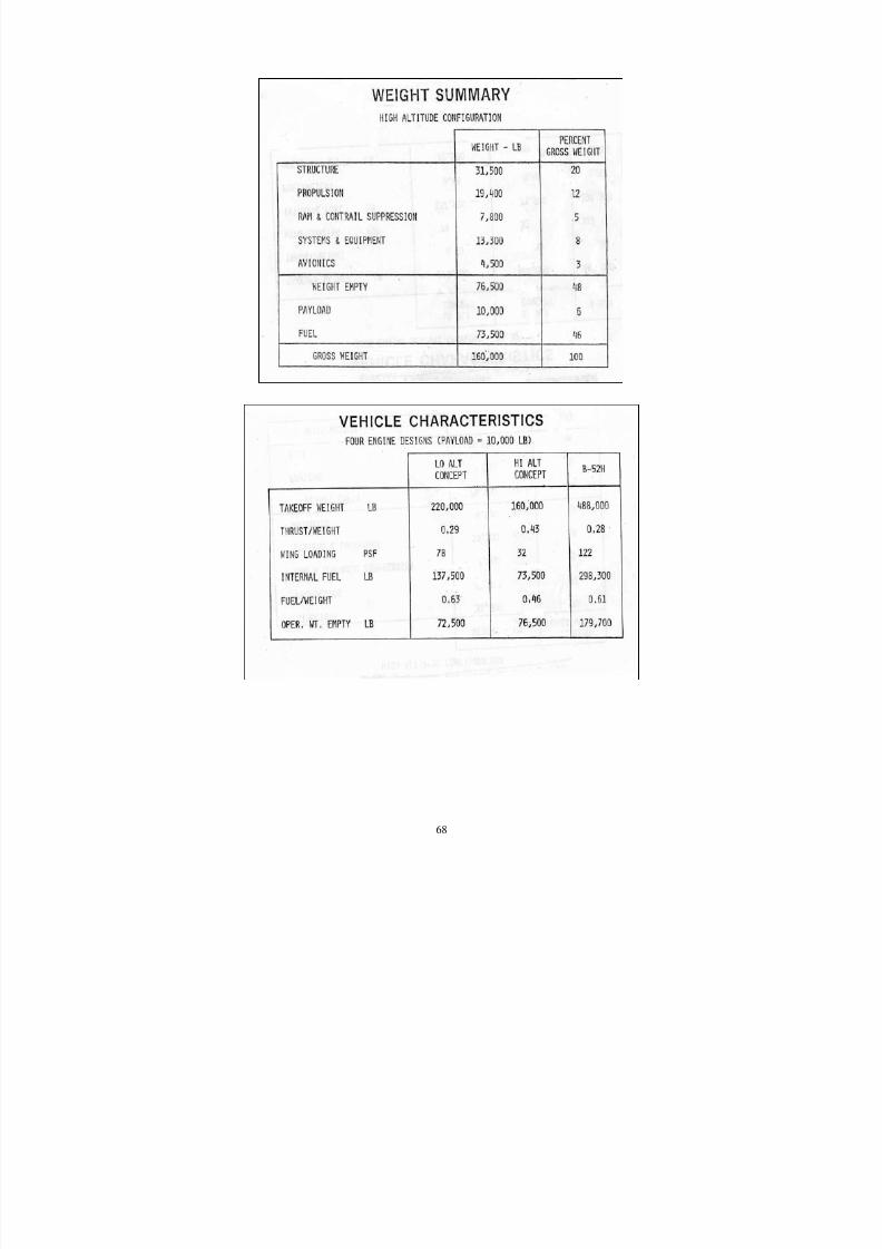
8/3/2019 B-2 Systems Engineering Case Studies
http://slidepdf.com/reader/full/b-2-systems-engineering-case-studies 82/118
68
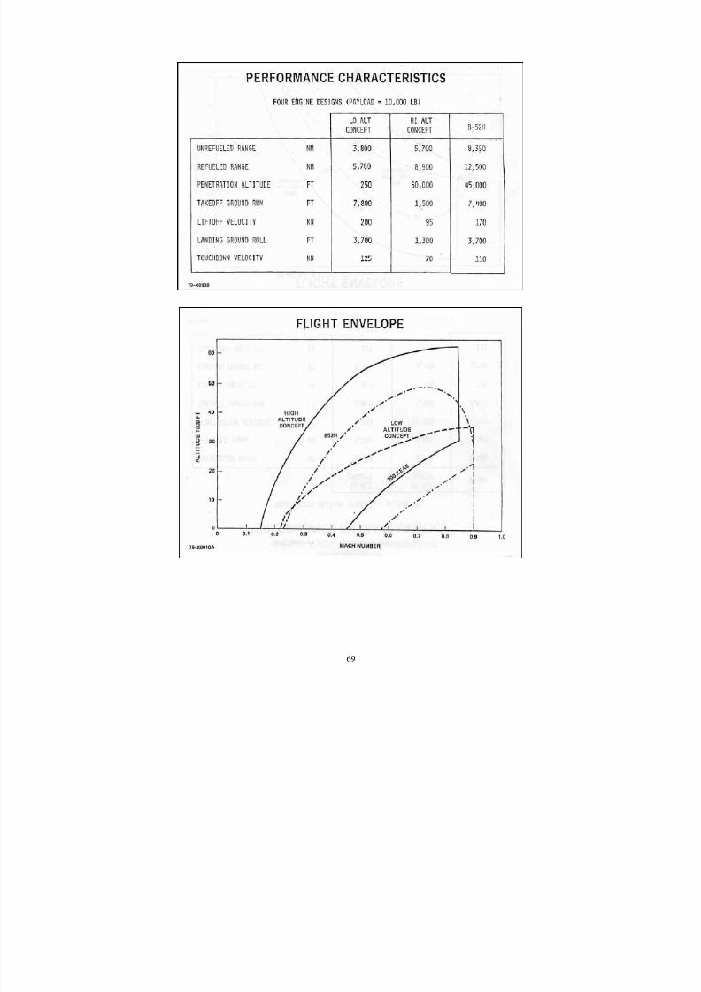
8/3/2019 B-2 Systems Engineering Case Studies
http://slidepdf.com/reader/full/b-2-systems-engineering-case-studies 83/118
69
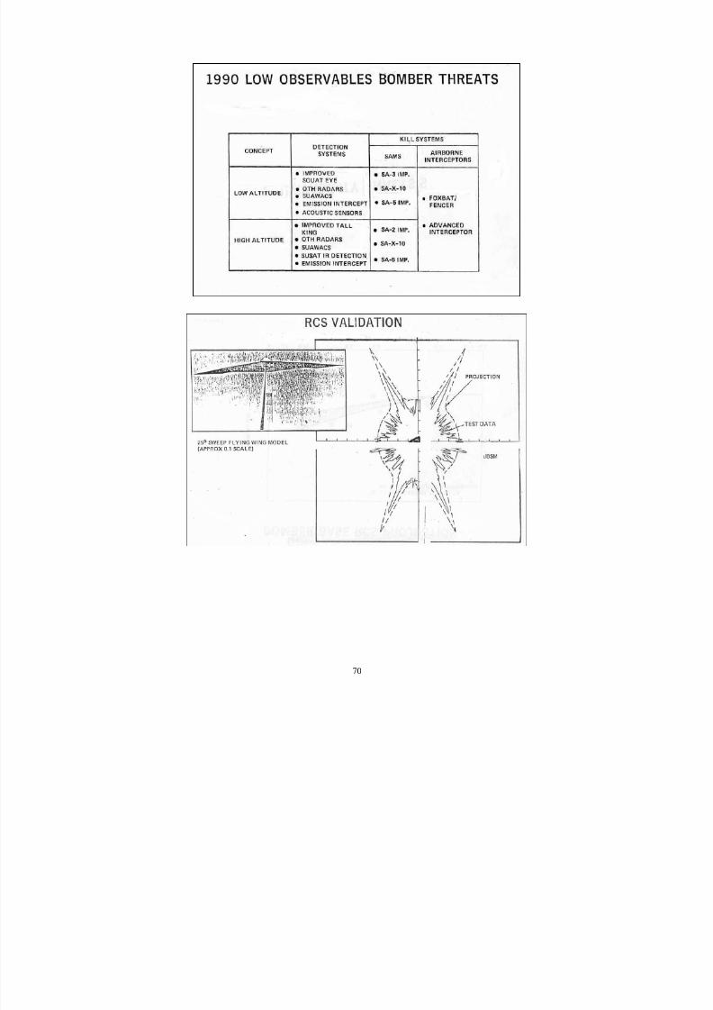
8/3/2019 B-2 Systems Engineering Case Studies
http://slidepdf.com/reader/full/b-2-systems-engineering-case-studies 84/118
70
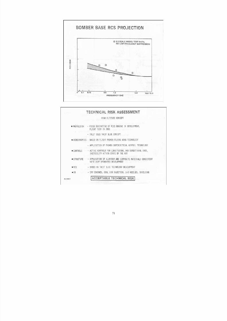
8/3/2019 B-2 Systems Engineering Case Studies
http://slidepdf.com/reader/full/b-2-systems-engineering-case-studies 85/118
71
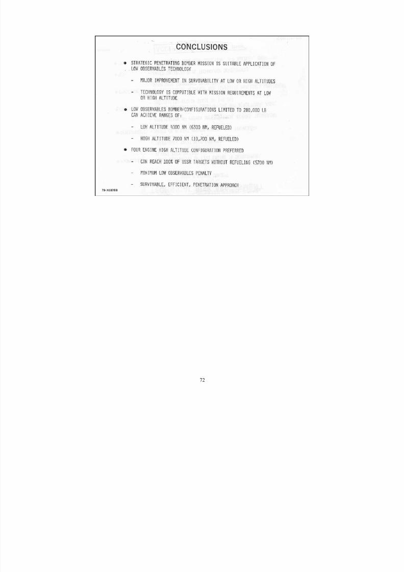
8/3/2019 B-2 Systems Engineering Case Studies
http://slidepdf.com/reader/full/b-2-systems-engineering-case-studies 86/118
72
8/3/2019 B-2 Systems Engineering Case Studies
http://slidepdf.com/reader/full/b-2-systems-engineering-case-studies 87/118
73
Appendix 5: Selected Text from B-2 SEMP
This appendix contains selected sections from the B-2 Systems Engineering ManagementPlan (SEMP)
• Section1 Introduction
• Section 3 Organization
• Section 4 WBS, Baselines, Specifications
• Section 4 Risk Management
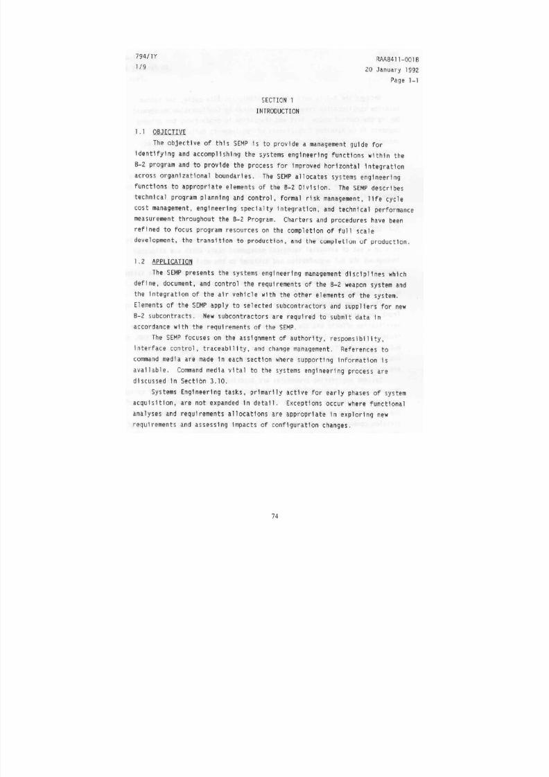
8/3/2019 B-2 Systems Engineering Case Studies
http://slidepdf.com/reader/full/b-2-systems-engineering-case-studies 88/118
74
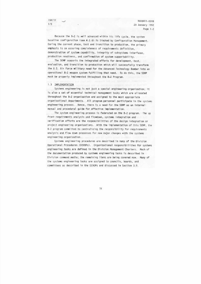
8/3/2019 B-2 Systems Engineering Case Studies
http://slidepdf.com/reader/full/b-2-systems-engineering-case-studies 89/118
75

8/3/2019 B-2 Systems Engineering Case Studies
http://slidepdf.com/reader/full/b-2-systems-engineering-case-studies 90/118
76
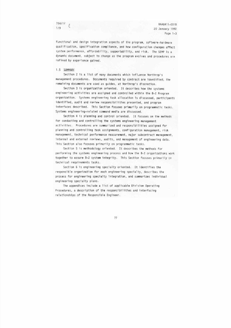
8/3/2019 B-2 Systems Engineering Case Studies
http://slidepdf.com/reader/full/b-2-systems-engineering-case-studies 91/118
77
8/3/2019 B-2 Systems Engineering Case Studies
http://slidepdf.com/reader/full/b-2-systems-engineering-case-studies 92/118
78
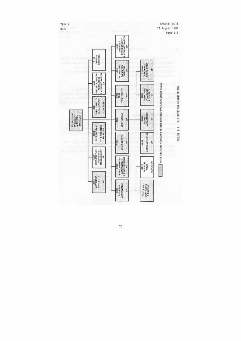
8/3/2019 B-2 Systems Engineering Case Studies
http://slidepdf.com/reader/full/b-2-systems-engineering-case-studies 93/118
79
8/3/2019 B-2 Systems Engineering Case Studies
http://slidepdf.com/reader/full/b-2-systems-engineering-case-studies 94/118
80
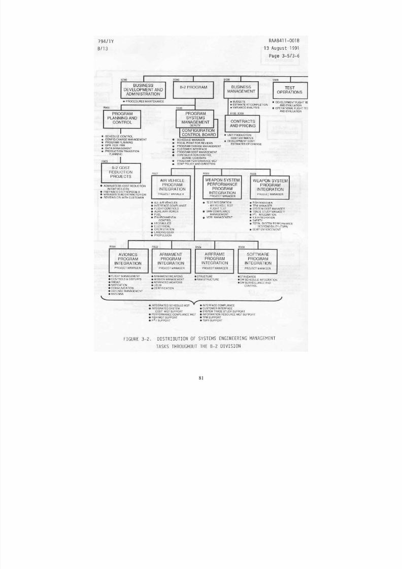
8/3/2019 B-2 Systems Engineering Case Studies
http://slidepdf.com/reader/full/b-2-systems-engineering-case-studies 95/118
81
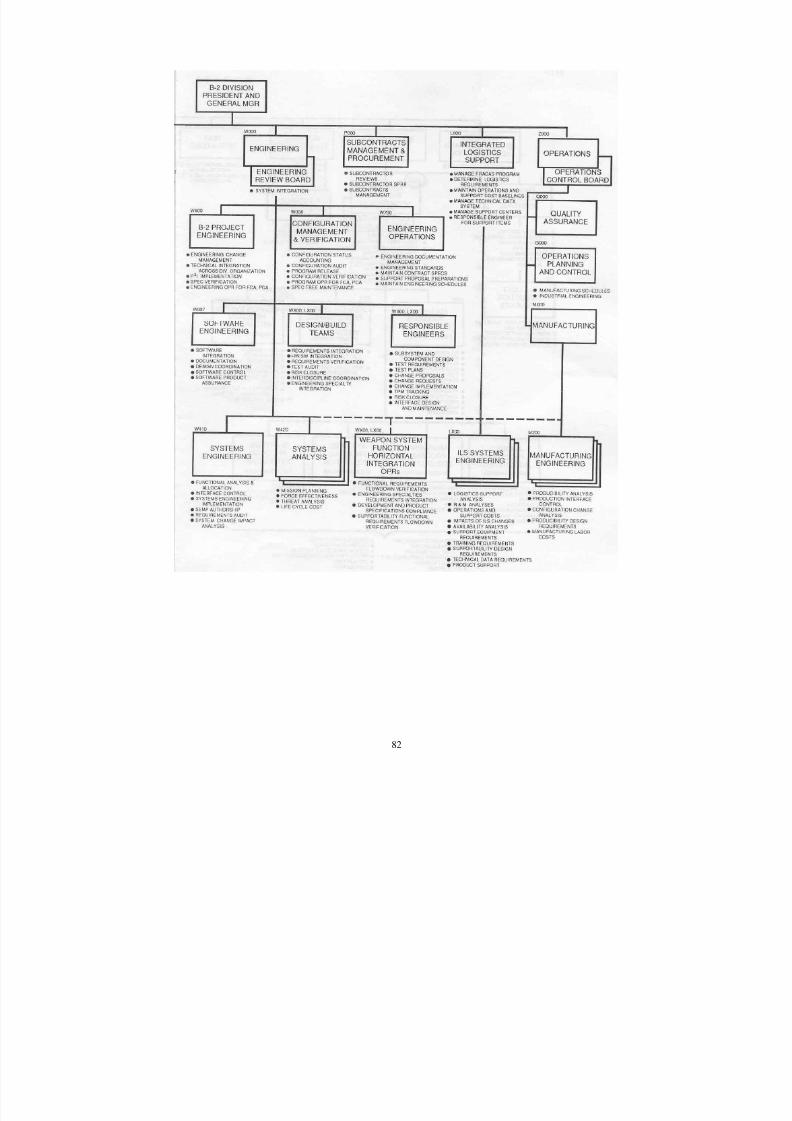
8/3/2019 B-2 Systems Engineering Case Studies
http://slidepdf.com/reader/full/b-2-systems-engineering-case-studies 96/118
82
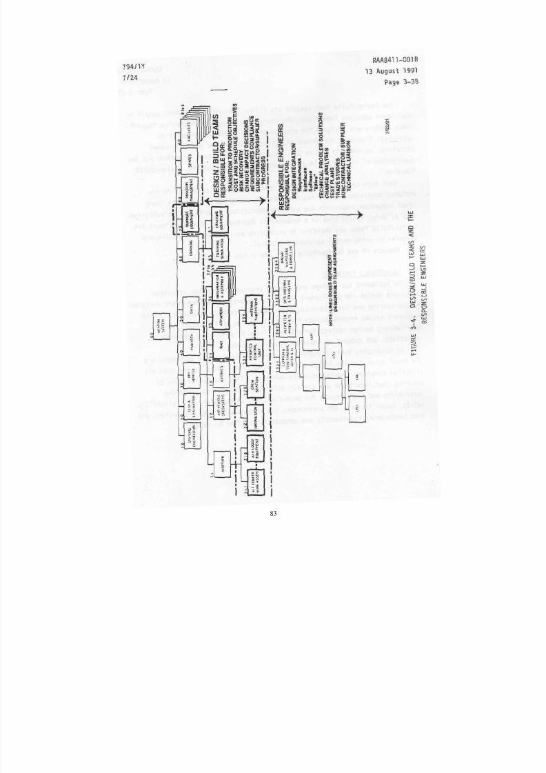
8/3/2019 B-2 Systems Engineering Case Studies
http://slidepdf.com/reader/full/b-2-systems-engineering-case-studies 97/118
83
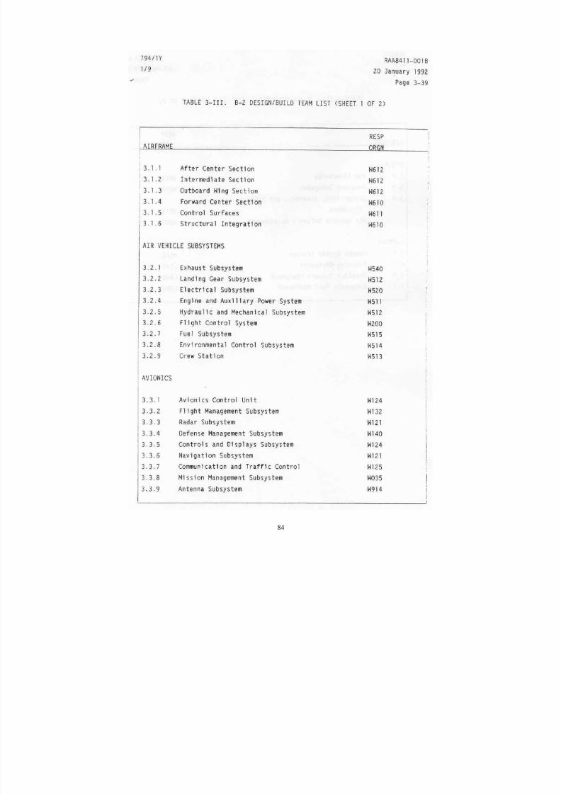
8/3/2019 B-2 Systems Engineering Case Studies
http://slidepdf.com/reader/full/b-2-systems-engineering-case-studies 98/118
84

8/3/2019 B-2 Systems Engineering Case Studies
http://slidepdf.com/reader/full/b-2-systems-engineering-case-studies 99/118
85
8/3/2019 B-2 Systems Engineering Case Studies
http://slidepdf.com/reader/full/b-2-systems-engineering-case-studies 100/118
86
8/3/2019 B-2 Systems Engineering Case Studies
http://slidepdf.com/reader/full/b-2-systems-engineering-case-studies 101/118
87
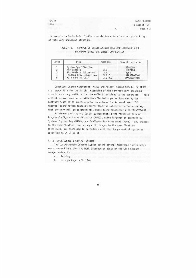
8/3/2019 B-2 Systems Engineering Case Studies
http://slidepdf.com/reader/full/b-2-systems-engineering-case-studies 102/118
88
8/3/2019 B-2 Systems Engineering Case Studies
http://slidepdf.com/reader/full/b-2-systems-engineering-case-studies 103/118
89
8/3/2019 B-2 Systems Engineering Case Studies
http://slidepdf.com/reader/full/b-2-systems-engineering-case-studies 104/118
90
8/3/2019 B-2 Systems Engineering Case Studies
http://slidepdf.com/reader/full/b-2-systems-engineering-case-studies 105/118
91
8/3/2019 B-2 Systems Engineering Case Studies
http://slidepdf.com/reader/full/b-2-systems-engineering-case-studies 106/118
92
8/3/2019 B-2 Systems Engineering Case Studies
http://slidepdf.com/reader/full/b-2-systems-engineering-case-studies 107/118
93
8/3/2019 B-2 Systems Engineering Case Studies
http://slidepdf.com/reader/full/b-2-systems-engineering-case-studies 108/118
94
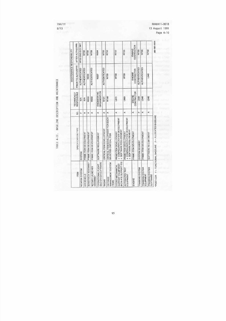
8/3/2019 B-2 Systems Engineering Case Studies
http://slidepdf.com/reader/full/b-2-systems-engineering-case-studies 109/118
95
8/3/2019 B-2 Systems Engineering Case Studies
http://slidepdf.com/reader/full/b-2-systems-engineering-case-studies 110/118
96
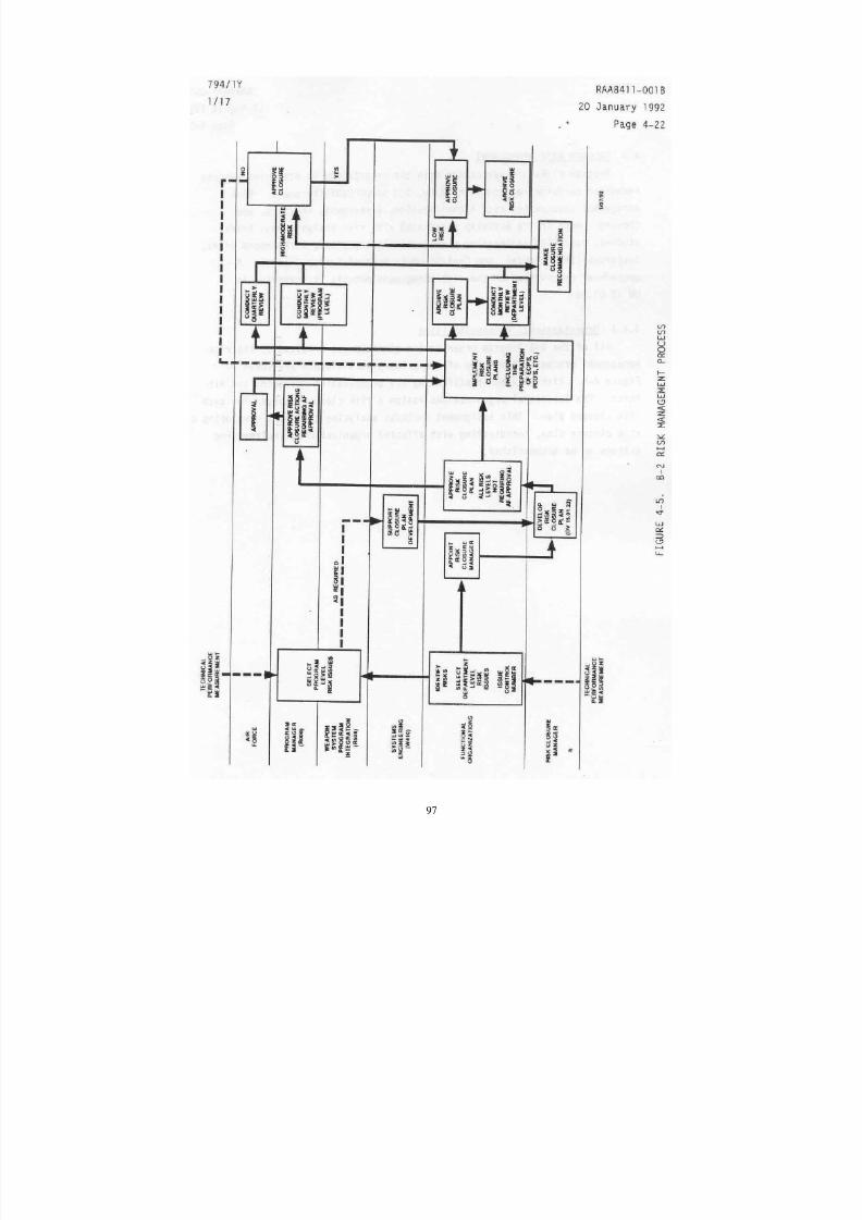
8/3/2019 B-2 Systems Engineering Case Studies
http://slidepdf.com/reader/full/b-2-systems-engineering-case-studies 111/118
97
8/3/2019 B-2 Systems Engineering Case Studies
http://slidepdf.com/reader/full/b-2-systems-engineering-case-studies 112/118
98
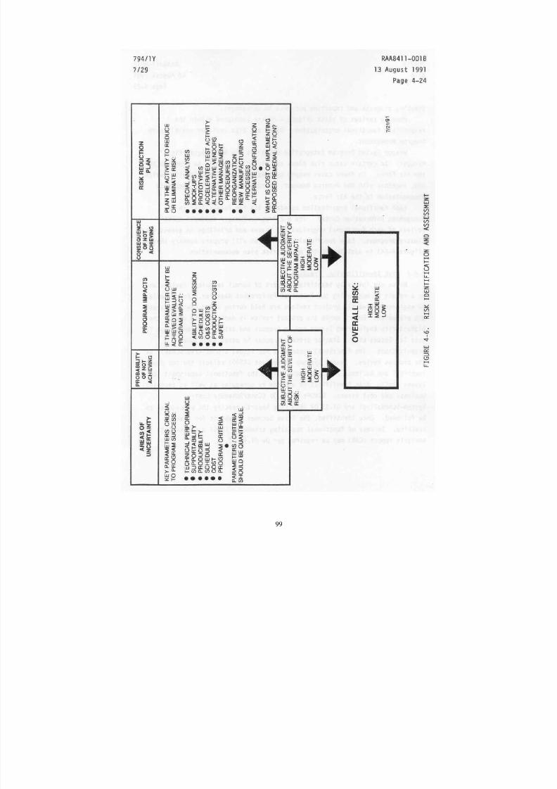
8/3/2019 B-2 Systems Engineering Case Studies
http://slidepdf.com/reader/full/b-2-systems-engineering-case-studies 113/118
99
8/3/2019 B-2 Systems Engineering Case Studies
http://slidepdf.com/reader/full/b-2-systems-engineering-case-studies 114/118
100
8/3/2019 B-2 Systems Engineering Case Studies
http://slidepdf.com/reader/full/b-2-systems-engineering-case-studies 115/118
101

8/3/2019 B-2 Systems Engineering Case Studies
http://slidepdf.com/reader/full/b-2-systems-engineering-case-studies 116/118
102

8/3/2019 B-2 Systems Engineering Case Studies
http://slidepdf.com/reader/full/b-2-systems-engineering-case-studies 117/118
103
8/3/2019 B-2 Systems Engineering Case Studies
http://slidepdf.com/reader/full/b-2-systems-engineering-case-studies 118/118