Embed Size (px)
Citation preview

Manual 7-6-16
1
Ayecka Broadband products - User Manual
Table of Contents
1. ABOUT .....................................................................................................................................2
2. SAFETY ....................................................................................................................................2
3. GENERAL .................................................................................................................................2
4. QUICK START / DEEP LOOK .......................................................................................................3
5. AYECKA PRODUCTS - ARCHITECTURE ........................................................................................5
6. NETWORKING OPTIONS ...........................................................................................................7
7. PRODUCT LINE AND SOLUTIONS ...............................................................................................8
8. SERIAL OVER USB CABLE ..........................................................................................................9
9. USER INTERFACE GENERAL ..................................................................................................... 10
10. NETWORKING MENU ............................................................................................................. 12
11. SYSTEM MENU ....................................................................................................................... 15
12. RX MANAGEMENT MENU ....................................................................................................... 16
13. TX MANAGEMENT MENU ....................................................................................................... 22
14. ACM MANAGEMENT .............................................................................................................. 26
15. TC1/ PRO CONFIGURATION .................................................................................................... 28
16. VALIDATING THE CONFIGURATION ......................................................................................... 35
17. IMAGES MANAGEMENT ......................................................................................................... 36
18. SR1CONTROL ......................................................................................................................... 37

Manual 7-6-16
2
1. About The user manual covers all Ayecka’s broadband products. The manual reviews the functionality and the configuration of the products.
This manual is aimed for technical people that have the experience and the background in IP over satellite. The reader should be able to answer at least one of the following questions:
● Why the quality of the signal in DVB-S2 is measured in Es/No, where in DVB-S it was in Eb/No? ● What is the destination MAC address of the multicast packet: 225.1.1.1?
The Document focuses on the SM1 in GSE mode and where MPE is relevant, the delta is described.
ST1 MPE and ST1 GSE configurations are similar in the transmission part of the SM1.
SR1 GSE and SR1 MPE are covered by the receiving part of the SM1.
TC1/ TC1Pro are covered in a separate part of this document
2. Safety Ayecka products are operated either by external (wall mount or desk top) 12V DC power supply or 100-250V AC.
In all installations the user must use caution and assure the units are properly placed, grounded, powered and connected.
Special attention must be given to grounding and protection of the cables coming from the antenna.
3. General 3.1. Control LED
The control LED should be green except when blinking during SW and FW loading.
RED can be due to several reasons:
● FPGA programing failed ● 10Mhz is absent ● 10Mhz was disconnected for short time ● Reset due to power cycles
See more details in the User interface General chapter
3.2. Image control Ayecka products keep two images of SW and FW on nonvolatile memory, one of them is active.
When upgrading a device, the non-active image is erased and a new image is downloaded in TFTP.
If the TFTP process fails, the device has only one image in the non-volatile memory. This does not stop the operation of the device in the short term, but can be an issue if sometime in the future the active image is erased.
When upgrading a device, please make sure the TFTP download was completed and the image is market ‘valid’
See more information in the Images management chapter.

Manual 7-6-16
3
4. Quick Start / Deep Look
4.1. Quick start 4.1.1. Connect Serial cable - Serial over USB Cable 4.1.2. Set IP address - Networking Menu 4.1.3. Set Tx RF - Tx Management menu 4.1.4. Set Encapsulation parameters - Tx Management menu 4.1.5. Set Rx RF parameters - Rx Management menu 4.1.6. Set Decapsulation parameters - Rx Management menu 4.1.7. Test the setup - Validating the configuration
4.2. Deeper look If you wish to get more information about the features below - please contact Ayecka
4.2.1. Flow Control - Buffer levels status messages from the SM1 allows implementation of simple Flow control of traffic form the LAN to the satellite. The SM1 also support Pause Frames where one can configure the Quanta size and interval.
4.2.2. Network connection / Isolation - Ayecka’s products have two external interfaces - Traffic and Management. The two can be connected or isolated on the switch level - Port isolation.
4.2.3. SDD output - The receiver can output over UDP status indications – Es/No (DVB-S2), Signal power, Lock and other. The information can be used to control the antenna position or constantly measure the reception quality.
4.2.4. BBF output - The receiver can be configured to output the BBF (in parallel to the De-GSE) allowing external processing.
4.2.5. The transport stream based receivers (Receivers operating in MPE) can filter any PID and send it on UDP for external processing.
4.2.6. Hardware indications - The SM1 has a connector with several FPGA GPIO. This can be used to support discrete indications like lock.
4.2.7. In-band control of the GSE Encapsulator/ Modulator - External control of the MODCOD, symbol rate, etc. can be done in two ways - Using SNMP via the control CPU or with UDP messages over the Traffic interfaces directly to the FPGA registers.
4.2.8. NCR lock - The SM1 modulator generate an NCR messages based on its 10Mhz clock. The Demodulator locks the 10Mhz of the board on incoming NCR. To lock a network, one can provide external 10Mhz to the Hub side and the remotes are locked. Each remote has 10Mhz out on 50Ohm SMA.
4.2.9. Multi stream - To deliver video (one transport stream) in parallel to data (L2 or L3) the SM1 uses 2 ISI. On one stream video is delivered as TS over BBF and in the other the data is delivered in GSE.
4.2.10. Tuner Filter Bandwidth - when the receiver is in blind search mode, auto detection of symbol rate, the tuner bandwidth can be configured. This is usefully if there are strong neighboring signals.
4.2.11. PSI/SI table insertion - the modulator in MPE can combine the encapsulated IP with external Transport stream form PSI/SI generator.
4.2.12. support of Eutelsat EBIS - The IP to MAC in MEP can be in the Eutelsat EBIS mode.
4.2.13. The SM1 includes an internal traffic generator for testing.

Manual 7-6-16
4
Important things to remember:
● To set static IP address you need to disable the DHCP option
● To activate 10Mhz output and BUC power you need to restart the modem
● Ping the interfaces and use statistics to verify traffic flow
● Telnet session may not start in first attempt, try second one. try “n” as well
● Default for Telnet time out is 30 sec. it can be configured in System->Telnet
● If you receive a VCM/ACM signal with marginal antenna. set the MODCOD filter and RX
Link Margin Thresholds as needed
● You can terminate telnet session form the Serial port with alt-x (the left alt)
● Receiver has two Rx inputs each 2 cfg sets - make sure the correct is active.
● Receivers support Search disable - enable it for initial lock.
● All Ayecka “Pro” products can output the SDD and BBF - For more information please
contact [email protected]
● To control the products using SNMP - first read the object ID and then use the correct
MIB. Object ID is 1.3.6.1.2.1.1.2 and an example of returned value form ST1 GSE is: 1:
sysObjectID.0 (octet string) 1.3.6.1.4.1.27928.105. The 27928 indicate Ayecka and 105 is
ST1 GSE
● Flow control intervals are in micro second units
● When MODCOD filter is active, it blocks BBF from entering the LDPC, The MODCOD of
the BBF will be displayed as they are received
● Make sure the device has two valid SW and FW images - Indication must be ‘V’. If
Indication is ‘O’, load additional image, if ‘X’ please contact [email protected]
● Ayecka products are built around GigE switch with 5 ports - Traffic, Management,
Internal, FPGA and management CPU. They can be all connected in one switch or
isolated to traffic and Management

Manual 7-6-16
5
GigE Switch
Mgmt CPU
FPGA
Sat. TX
Sat. RX Traffic
MGMT
Internal
LNB Power
BUC Drive Power / 10Mhz
10Mhz
NCR
5. Ayecka Products - Architecture Ayecka products are divided to the following groups: IP over DVB-S2 communication - Including the ST1 (IP Modulator), the SR1 (IP Demodulator) and the SM1 (IP over DVB-S2 Modem). and Misc. DVB-S2 functionality - Including the TC1 (Transport converter), the TM1 (Transmodulator) and others. All Ayecka products share common architecture around internal GigE switch - the traffic port, the management port, the control CPU and the FPGA processing the traffic, are all ports of a GigE, non-blocking switch.
The board has 3 ports: Traffic - where traffic to/from the satellite is forwarded MGMT - The Management interface Internal - Internal port facing into the chassis, application platform for Web interface controller or router board internal to the 19’’ chassis Ports can be connected into one LAN or isolated (Traffic and FPGA separated from MGMT, Int. and CPU) The traffic is processed (encapsulated, de-capsulated and modulated) by the FPGA in wire speed. The Products share same images structure:
● Software - running on the control CPU with file extension .asw ● Firmware - Configuration file of the FPGA with file extension .afp ● Bootloader - Software used to boot the CPU with file extension .asw
Images are uploaded using TFTP. Each device saves on a nonvolatile memory two versions of the SW and of the firmware. More about the SW upgrade see below All our products support management using serial over USB, telnet and SNMP. Web based interface is optional either by using an additional controller board internal (in 19’’ rack mount chassis) or external on the management LAN.
Manual 7-6-16
6
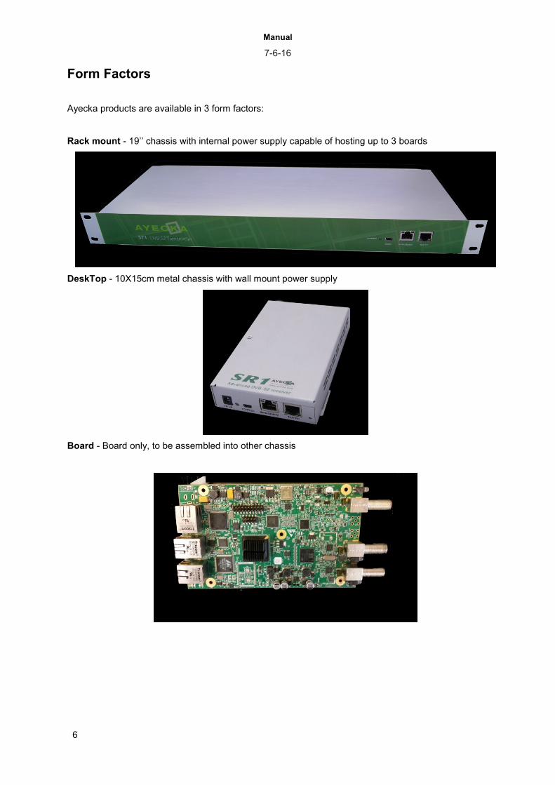
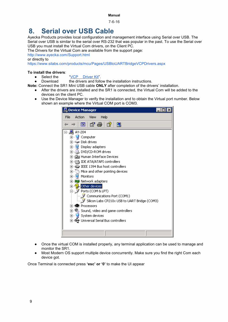
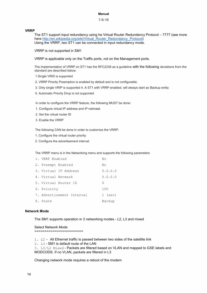
Form Factors
Ayecka products are available in 3 form factors:
Rack mount - 19’’ chassis with internal power supply capable of hosting up to 3 boards
DeskTop - 10X15cm metal chassis with wall mount power supply
Board - Board only, to be assembled into other chassis

Manual 7-6-16
7
6. Networking options
Ayecka products can operate in L2, L3 or Mixed mode. In all modes, the processing is done by the FPGA in wire speed.
In L2 mode Ethernet packets passes the GigE switch and encapsulated into GSE over DVBS2 Base Band Frame (GSE/S2BBF). The S2BBF are transmitted with configured MODCOD, ISI and Frame Type. Broadcast packets are forwarded by the switch also to the CPU, so ARP and similar protocol are handled. Ethernet packets with DST MAC of the unit are forwarded by the FPGA to the CPU so ICMP (like Ping) are handled. Ayecka products have internal switch - so in L2 mode we are practically connecting the two switches In L3 the Ethernet packets that has the DST MAC of the device are processed. The IPV4 payload is extracted and based on the forwarding table, dropped or passed to the encapsulator. In mixed mode - Ethernet packets are filtered based on VLAN ID. If the VLAD ID appears in the VLAN filter table, the Ethernet packet is forwarded to the GSE encapsulator. If the packet is not in the VLAN filter table, or does not have VLAD ID, its IPV4 payload is forwarded to the IP forwarding, if passed, sent to the encapsulator. In Mixed mode the S2 stream can include GSE packets with both Ethernet or IP in them.
GSE Encap
GigE
Switch
GSE Encap
VLAN Filter
GSE Encap
IP Forwarding table
GigE
Switch
GigE
Switch
IP Forwarding table

Manual 7-6-16
8
7. Product Line and Solutions
Product Features use
SM1 ● Two way, DVB-S2, SCPC modem with GSE encapsulation
● ACM, Pre-distortion and AUPC embedded ● L2 and L3 network interfaces
● P2P and P2MP connectivity over satellite
● Backhauling
ST1 MPE
● MPE IP encapsulator with CCM DVB-S2 Modulator.
● The ST1 MPE support NCR insertion in CCM and ACM mode
● TSoIP input to combine video and data and inject external tables
● TS output to multiplex MPE with video
● Legacy data service - using MPE
● SmartLNB forward channel
ST1 Encap Only
● MPE IP encapsulator with TS over IP output of encapsulated traffic
● Legacy Data services multiplexed with video
ST1 GSE ● GSE IP encapsulator with ACM DVB-S2 Modulator
● support insertion of NCR in ACM mode ● support Flow toward the LAN
● New data services using GSE
● VSAT networks
ST1 BBF ● VCM DVB-S2 modulator with BBF over UDP input according to SatLab L.2
● Advanced data networks where external encapsulator is used
SR1 MPE ● DVB-S2 ACM receiver with MPE decapsulator
● Legacy data service - using MPE
SR1 GSE ● DVB-S2 ACM receiver with GSE decapsulator
● New data services using GSE
SR1 Pro GSE
● -Based on advanced demodulator and support more features then the SR1 -GSE
● New data services using GSE
● Narrow band services down to 100Ksps
TC1 ● Convert transport stream to IP over GigE ● TC1 provides Es/No, and power reading
over UDP ● IP and ASI outputs ● TC1 Pro offers additional features like I/Q
and BBF output ● Tc1 Pro egress include statistics on
number of packets per MODCOD
● Low cost free to air reception
● Deep inspection of MPE networks- Send to the GigE port the I and Q samples of the received S2 signal
TC1 BBF ● Forward BBF to IP according to SatLab L.3 Protocol
● Deep packet analysis of IP over GSE over S2
TC1 Const. ● Send to the GigE port the I and Q samples of the received S2 signal
● signal quality analyses
Manual 7-6-16
9
8. Serial over USB Cable Ayecka Products provides local configuration and management interface using Serial over USB. The Serial over USB is similar to the serial over RS-232 that was popular in the past. To use the Serial over USB you must install the Virtual Com drivers, on the Client PC. The Drivers for the Virtual Com are available from the support page: http://www.ayecka.com/Support.html or directly to https://www.silabs.com/products/mcu/Pages/USBtoUARTBridgeVCPDrivers.aspx To install the drivers:
● Select the “VCP Driver Kit”. ● Download the drivers and follow the installation instructions.
Note: Connect the SR1 Mini USB cable ONLY after completion of the drivers’ installation. ● After the drivers are installed and the SR1 is connected, the Virtual Com will be added to the
devices on the client PC. ● Use the Device Manager to verify the installation and to obtain the Virtual port number. Below
shown an example where the Virtual COM port is COM3.
● Once the virtual COM is installed properly, any terminal application can be used to manage and monitor the SR1.
● Most Modern OS support multiple device concurrently. Make sure you find the right Com each device got.
Once Terminal is connected press ‘esc’ or ‘0’ to make the UI appear

Manual 7-6-16
10
9. User interface General
The Terminal Base User Interface is managed by selecting menu items, defining values, and saving the revisions, as follows.
● Selecting Items – Press the relevant number or letter. ● Setting Values – Enter the relevant value, or select from a list of options. Once the value
has been entered or selected, press Enter. ● Toggle – When there are only two options for setting, selection will toggle between the
two. ● Save to Non Volatile Memory (NV memory or Flash memory): Press 0 to save the new
value to the non-volatile memory of the SR. ● Time out: If after 30 from entering to a menu, it is not save to NV memory, a warning message
will appear. The Menu Time out is configurable. Tips
1. default time out for the Telnet session and menu time out is 60 sec. It may be too short. to change it use the “system “menu
2. There is no firewall or other protection mechanism on the Management interface. Top Menu Below is an example of a top menu (of SM1g). The top menu DOES NOT auto refresh, press ’0’ or ESC to refresh ============================================================================= SM1g Serial No. 300491 51ADA 52C Run Time: 632:03:22 SW Ver 11.00b56 V HW Ver 6.21 FW Ver 11.00b018 V BL Ver 1.01b14 RX1: Active, Locked Profile 1 1200.000 MHz, DVB-S2 8PSK 5/6, 44.994 Msps, ACM, 15.7 dB RX2: Not Active, Not Locked Profile 1 1100.000 MHz, Auto TX: DVBS2, 1523.525 MHz, SR 45000000 sym/sec, RO 20%, BR (in) 103439.568 Kbps ============================================================================= Configuration 1. Configuration 2. Status 3. Network 4. System 5. Statistics SM1g - Product name Serial No. - Product serial number 51ADA - Demodulator chipset version 52C - Board Temperature Run Time - Elapsed time since last reboot ! ,X - Indicate events that effect run time SW - Software Version - Guess... HW - Hardware Version - Board version FW - Firmware Version - FPGA version BL - Boot Loader Version - Version of boot loader V,X,O - Indication of number of valid images on the On Board Flash storage. ‘X’ - No images on Flash (only on the CPU internal Flash), ‘O’ - Only one valid image on Flash. ‘V’ - two valid images. If indication is not ‘V’ - please use TFTP to load additional image. !, X - Indicates cause of device reset.

Manual 7-6-16
11
! - Indicates that reset of the device occurs as result of jitter/no 10Mhz clock for FPGA. "X" Indicates that reset of the device occurs as result of power failure If indication is ‘X’ or ‘!’, please contact [email protected] RX1 / RX2 - Active, Status Profile name, settings TX - On/off, Symbol rate, Roll-off, Bit rate is the bit rate entering the modulator

Manual 7-6-16
12
10. Networking Menu Below is an example of networking menu of Ayecka products. The menu may look different in some products. The menu below is of the SM1. Other product may have slightly different features.
Network =======
1. Management IP Address 0.0.0.0 2. Management IP Mask 0.0.0.0 3. Management Ethernet Address CC-F6-7A-AB-12-1F 4. Management IP Multicast Off 5. Management DSCP 0 6. Management VLAN ID 0 7. Management Default Gateway 0.0.0.0 8. Management DHCP Client On 9. Management Port State Enabled
A. LAN IP Address 192.168.11.102 B. LAN IP Mask 255.255.255.0 C. LAN Ethernet Address CC-F6-7A-AB-12-1A D. LAN IP Multicast On E. Router IP Address 192.168.11.79 F. LAN DHCP Client Off G. ARP Management H. Jumbo Frame Mode 1522
I. Air IP Address 192.168.1.161 J. Air Ethernet Address CC-F6-7A-AB-12-19 K. Isolate Networks Isolated L. Flow Control M. Network Mode L2 Mode
N. LAN VLAN ID 0 - Set the VLAN of the traffic port. 0 means no
VLAN tagging O. LAN Phy 100BaseT Unforced - Allow forcing the Traffic
port to 100BaseT in autonegotiation.
The network menu is divided to Management part, Traffic part, AIR and general Management
● The Management interface is used for Telnet, SNMP and TFTP. It is limited to one at the time. ● Support selection of manual or dynamic configuration of the IP address - see #8 - DHCP client ● The MAC address is read only ● By default multicast is blocked on the managements interface ● The management traffic can be colored with DSCP and VLAN tag. ● The management interface can be disabled, leaving only the serial
Traffic (LAN)
● Support disable of Multicast traffic from satellite to the LAN ● ARP management is a mechanism where the device constantly sends ARP request to the default
gateway to verify that the unit is connected. In case of no ARP reply a SNMP trap is sent over the Management interface. By default, ARP Table IP == Routers IP, if the ARP Table IP modified in the MMI, it will take the new value. If it set to 0.0.0.0, the Router’s IP will be used again. Part of the ARP management is display of the ARP cache table. The use of Arp Table IP Address allows running ARP on sub net, even if the LAN interface is not part of it.
Air
● In use only in receiver (SR1, SREGSE, SR1 Pro GSE) - this MAC can be used in the encapsulator as destination MAC or Label
Isolate Network

Manual 7-6-16
13
● One can connect or isolate the management and the traffic (LAN) network Flow Control The transmitting devices like ST1 and SM1, support two mechanisms for Flow control - one is the Pause frames and the other is sending a periodic message with indication of their internal buffer levels. this indication can be used for accurate flow control when ACM is used. The input buffer has two main stages - the Ethernet input buffer and the Modulator. total is 96KByte
Pause frames are send destination MAC 01-80-C2-00-00-01 (and not with the MAC set for the Flow control) Flow Control ======================== 1. Flow Control ON
2. IP Address 192.168.10.101 - Make sure the device knows the MAC of this
IPInterval in microseconds units 3. Port 1234
4. Interval [usec] 100000 - Interval in microseconds units 5. Pause Packet Disabled
The Flow control message structure (starting form beginning of UDP)
Byte Byte Byte Byte
0x0 Sync Byte=0xC0 Packet Counter 1ms Tick Counter
0x4 Number of bytes in both ST1g Buffers (TSE & Modulator) out of 96Kbyte
0x8 Number of bytes in the TSE Buffer out of 32KByte
0xC
Number of bytes in the Modulator Buffer out of 64KBytes
0x10 Bitrate of Incoming Ethernet Packets
0x14 Counter of Incoming Ethernet Packets
0x18 Counter of Dropped Ethernet Packets due to buffer overflow
0x1C Bitrate of Routed GSE Packets, Only packets that passed gse routing table
0x20 Bitrate of Transmitted GSE Packets, Only packets that were actually encapsulated and transmitted
0x24 Counter of Transmitted GSE packets, only packets that were actually encapsulated and transmitted
12:23:26.731518 IP 192.168.9.102.1233 > 192.168.9.142.5555: UDP, length 44 0x0000: 4500 0048 03d7 0000 8011 a289 c0a8 0966 E..H...........f 0x0010: c0a8 098e 04d1 15b3 0034 0000 c0d7 0fdf .........4...... First Byte
0x0020: 0001 2d99 0000 7a02 0000 b397 004d 00c0 ..-...z......M.. 0x0030: 0000 b535 0000 48ea 0009 dbc0 0000 0a00 ...5..H......... 0x0040: 0009 df80 0000 0ae8 ........
Manual 7-6-16
14
VRRP
The ST1 support input redundancy using he Virtual Router Redundency Protocol – 7777 (see more here http://en.wikipedia.org/wiki/Virtual_Router_Redundancy_Protocol) Using the VRRP, two ST1 can be connected in input redundancy mode. VRRP is not supported in SM1 VRRP is applicable only on the Traffic ports, not on the Management ports. The implementation of VRRP on ST1 has the RFC2338 as a guideline with the following deviations from the
standard are described below:
1.Single VRID is supported
2. VRRP Priority Preemption is enabled by default and is not configurable.
3. Only single VRIP is supported 4. A ST1 with VRRP enabled, will always start as Backup entity
5. Automatic Priority Drop is not supported
In order to configure the VRRP feature, the following MUST be done:
1. Configure virtual IP address and IP netmask
2. Set the virtual router ID
3. Enable the VRRP
The following CAN be done in order to customize the VRRP:
1. Configure the virtual router priority
2. Configure the advertisement interval.
The VRRP menu is in the Networking menu and supports the following parameters
1. VRRP Enabled No
2. Preempt Enabled No
3. Virtual IP Address 0.0.0.0
4. Virtual Netmask 0.0.0.0
5. Virtual Router ID 0
6. Priority 100
7. Advertisement Interval 1 (sec)
8. State Backup
Network Mode
The SM1 supports operation in 3 networking modes - L2, L3 and mixed Select Network Mode ========================
1. L2 - All Ethernet traffic is passed between two sides of the satellite link
2. L3 - SM1 is default route of the LAN
3. L3/L2 Mixed - Packets are filtered based on VLAN and mapped to GSE labels and
MODCODS. If no VLAN, packets are filtered in L3 Changing network mode requires a reboot of the modem
Manual 7-6-16
15
11. System Menu
1. Warm Reset - Reset the software but does not reload the FPGA
2. Cold Reset - reset the software and reload FPGA
3. Restore Factory Defaults and Reset - Reset configures to the values set in
production, deleting all configurations performed later. Please consult us before doing it
4. Telnet - All Telnet relates settings including the username, password and timeout.
5. NTP Server IP Address - for future use
6. SNMP Trap Server IP Address - The SNMP Trap Server IP Address menu sets the
SNMP Trap server IP address
7. SNMP Read Community
8. SNMP Write Community
9. Events Configuration - Control if events will be reflected on the console and SNMP
traps
A. Software Upgrade
B. FPGA Image Upgrade
C. Hardware Information
D. Menu Timeout - After time out, the User interface will change to upper menu
E. Factory Settings - password protected sub menu to set the product parameters like
MAC address, SN etc.
F. Bootloader Upgrade
G. Demod Path Reset - reset the Demodulator including its LDPC
H. Main Menu Refresh Time 5 seconds
I. Firmware Reset - Reset the Firmware only

Manual 7-6-16
16
12. Rx Management menu
The RX management is common to the receivers and Modem products.
Ayecka products use two types of demodulator the STV0900 (In SR1 and TC1) and the STV0910 (in the Pro versions). The STV0910 support wider symbol rate range - starting from 100Ksps up to 67Msps.
Ayecka products have 2 physical RF inputs, each with its own tuner. The Demodulator is common but can operate in single or dual mode.
Each Rx has two configuration parameters sets (Rx frequency, Tuner Acquisition Bandwidth, LNB powering, Decapsulation, etc.)
The receivers support automatic or manual mode of selection of Rx inputs and configuration sets.
An example is where RX selection is manual and RX1 is selected, and the Configuration Sets Management is automatic. In this case the signal is received only form Rx1 but if configuration set 1 does not lock, the unit will automatically try configuration set 2 after Profile Switch Period.
Below are the menus related to RX management:
12.1. Rx top menu The top menu deals with the selection of the physical inputs, R21 or Rx2:
1. Config RX Channel 1
Tuner Filter BandwidthTuner Filter BandwidthTuner Filter BandwidthTuner
Filter Bandwidth2. Config RX Channel 2
3. Select Active RX Channel
4. RX Channel Switching Auto - selecting if switching between RX1 to RX2 is manual
or automatic
5. RX Channel Operation Mode Single - Selecting of Demodulator is in single mode,
switching between the two Rx inputs, or in dual mode where two RX are working simultaneously.
6. RX Data Stream Mode Frame - Determine if the receiver is processing Transport
stream (in MPE mode or in TC1) or processing BBF (GSE mode or TC1 BBF)
7. Number of Transport Filters 8 / 0 - Determine how the De-Capsulation filters are divided
between the two Rx inputs in dual mode of the Demodulator
8. MODCOD Filter - enable controlling
12.2. Rx menu Each Rx has a menu that control the selection of the Configuration sets. Here is an example where Rx1 is the active menu:
1. Configuration Set 1 Active
2. Configuration Set 2 Not Active
3. Configuration Sets Management

Manual 7-6-16
17
Each configuration set has its menu
1. Tuner Frequency 1000.000 MHz - L-Band Frequency in 1Khz resolution
2. Tuner Acquisition Bandwidth 10.000 MHz - The range of searching, in this case +/-
10Mhz around the Tuner frequency
3. Standard DVB-S2 - Default is S2. In case of S the demodulator is
changing automatically.
4. Coding Mode CCM - Default is CCM, in case of VCM signal demodulator is
changing automatically.
5. Symbol Rate Auto - If left Auto, the demodulator will calculate
automatically the symbol rate. If set to value, the demodulator will lock only on the configured symbol rate. For symbol rates below 1Msps a manual setting is needed
6. MODCOD Auto
7. RollOff Auto
8. Pilot Auto
9. Spectral Inversion Auto
A. Gold Code 0
B. Frame Type Auto
C. Encapsulation MPEG-TS
D. ISI 255 - Default is 255, where the demodulator is passing all
ISI and filtering is done in GSE level.
E. Filters Table flow control - configuration of the MPE or GSE De-Capsulation parameters
F. LNB power 18V
G. LNB compensation Off - In case of long cable, 1V is added to LNB power
H. 22 KHz On
I. Status Active
J. Profile Name Profile 1 - Fee text to appear on top menu
K. Tuner Filter Bandwidth 72.000 MHz - set tuner BW when in blind search

Manual 7-6-16
18
12.3. MODCOD filters
There are two levels of MODCOD filtering
First is a bit array of ‘1’ or ‘0’ per MODCOD. The Second are the MODCOD thresholds
See more in the Rx tips below
12.4. De- capsulation Menu
Ayecka products support two types of encapsulation - MPE (legacy and inefficient) and GSE (modern, efficient and flexible). The configuration of each type is different. The De-Capsulation
12.4.1. MPE
Below is an example of MPE table with 8 entries:
RX Transport Filter Table
=========================
Slot. PID Ethernet Address Status IP Multicast
1. 646 CC-F6-7A-05-20-E9 Enabled Pass
2. 0 CC-F6-7A-05-20-E9 Disabled Block
3. 0 CC-F6-7A-05-20-E9 Disabled Block
4. 0 CC-F6-7A-05-20-E9 Disabled Block
5. 0 CC-F6-7A-05-20-E9 Disabled Block
6. 0 CC-F6-7A-05-20-E9 Disabled Block
7. 0 CC-F6-7A-05-20-E9 Disabled Block
8. 0 CC-F6-7A-05-20-E9 Disabled Block
Below is an example of setting filter for unicast traffic on Specific PID, with destination MAC address as specified
RX Transport Filter Record #1:
===============================
1. PID 601
2. Ethernet Address: CC-F6-7A-04-B7-44
3. Status: Enabled
4. IP Multicast: Block
PID – in decimal number
Ethernet Address – 6 bytes in Hex
IP Multicast: Select this option to toggle Multicast enable or disabled for the filter
Status: Select this option to toggle the status of the filter Enabled or Disabled.

Manual 7-6-16
19
The example below describes how to set the filter pass all multicast traffic on a specific PID
Note:
When setting the filter for multicast only, the Ethernet address has no meaning. The filter will pass all Multicasts.
RX Transport Filter Record #2:
===============================
1. PID: 203
2. Ethernet Address: D1-51-4C-9C-90-00
3. Status: Active
4. IP Multicast: Pass
The example below shows setting the filter to pass only multicast traffic with a destination IP address of 225.1.1.1 on a specific PID. The Multicast address of 225.1.1.1 is translated to the multicast MAC address of 01-00-5E-01-01-01
RX Transport Filter Record #3
==============================
1. PID 401
2. Ethernet Address 01-00-5E-01-01-01
3. Status Enabled
4. IP Multicast Pass
12.4.2. GSE
Below is an example of GSE table with 8 entries:
RX Transport Filter Table
=========================
N Type Label ISI Pass BC Ena
1 6 Byte 01-00-5E-01-01-01 3 No Yes
2 6 Byte 00-00-00-00-00-00 0 No No
3 6 Byte 00-00-00-00-00-00 0 No No
4 6 Byte 00-00-00-00-00-00 0 No No
5 6 Byte 00-00-00-00-00-00 0 No No
6 6 Byte 00-00-00-00-00-00 0 No No
7 6 Byte 00-00-00-00-00-00 0 No No
8 6 Byte 00-00-00-00-00-00 0 No No
RX Transport Filter Record #1
==============================

Manual 7-6-16
20
1. Label Type 6 Byte
2. Label 01-00-5E-01-01-01
3. ISI 3
4. Pass Broadcasts No
5. Enabled Yes
Label type – Select if Label is 3 Byte, 6 Byte. Press ‘1’ to switch between modes
Label – Value of the Label
ISI - Set the ISI value
Pass Broadcast: Select if to pass or block boradcast packets
Enabled: Enable or Disable the entry
12.5. RX Tips The following are tips to keep in mind when configuring the receivers
● When setting Symbol rate to automatic mode, the receiver can lock on neighbor signal. ● When locking on narrow signals, down to 100Ksps, make sure Tuner Acquisition Bandwidth is set
to reasonable value. ● Lock time is composed of search time (can be controlled by Tuner Acquisition Bandwidth) and the
demodulator lock that depends on Es/No, MODCOD etc). Some receivers support disable of the scanning (Search Enable/Disable). When search is disabled the demodulator is re-locking on last good known parameters. Re-lock time can be few msec for symbol rates of few Msps and higher, or less then 1 sec for narrow signals of 100Ksps.
● Multi stream signals - In multi stream signals some receivers are limited- MODCOD filtering address the issue
● RX Link Margin Thresholds - When working in VCM mode the SR1 holds an internal Es/No to MODCOD table (based on the standard). The operator can add thresholds on top of the standard values. If Current Es/No is below Nominal + Lower threshold, the Demodulator will stop processing the MODCOD, When Es/No is better than Nominal + Upper threshold the Demodulator will start to process the MODCOD.
● MODCODS Filter - This is a bitmap of the MODCODs that the demodulator will process, regardless of Es/No. The bit map is according to the standard:
Bit MODCOD Bit MODCOD Bit MODCOD
0 frame - DO not set to 1 10 QPSK 8/9 20 16APSK 4/5
1 QPSK 1/4
11 QPSK 9/10 21 16APSK 5/6
2 QPSK 1/3 12 8PSK 3/5 22 16APSK 8/9
3 QPSK 2/5 13 8PSK 2/3
23 16APSK 9/10
4 QPSK 1/2 14 8PSK 3/4
24 32APSK 3/4
5 QPSK 3/5 15 8PSK 5/6
25 32APSK 4/5

Manual 7-6-16
21
6 QPSK 2/3 16 8PSK 8/9
26 32APSK 5/6
7 QPSK 3/4 17 8PSK 9/10
27 32APSK 8/9
8 QPSK 4/5 18 16APSK 2/3
28 32APSK 9/10
9 QPSK 5/6 19 16APSK 3/4
Example:
Only 8PSK3/5 Mask 1000 Hex
Only 16APSK2/3 40000 Hex
Both 8PSK3/5 and 16APSK2/3 mask 41000 Hex

Manual 7-6-16
22
13. Tx Management menu
TX management control the following
● Tx Frequency ● TX power ● Behavior after power cycle - should the TX be off or same as before the power cycle. ● Symbol rate ● MODCOD/ISI/Frame Type - This is common to all traffic in CCM and set individually in VCM /
ACM mode ● BUC power and 10Mhz reference ● Encapsulation - MPE or GSE
13.1. Tx top menu The top menu deals with the selection of TX:
TX Configuration
================
1. TX Configuration
2. Modulator Configuration
3. GSE Configuration
4. BUC Control
TX Configuration – Configure the Tx parameters - Tx Frequency, Power level, etc.
Modulator Configuration – Configure the Modulator part - Symbol rate, RO, etc.
GSE Configuration - Configure the encapsulation in MPE or GSE accordingly
BUC Control - Control the Power and 10Mhz reference to BUC
13.2. Tx Configuration
TX Configuration
===============
1. TX Frequency 1400.000 MHz
2. TX Power Level -40.0 dBm
3. TX Output Power Off
4. TX Output Power On Powercycle User-Defined
5. TX Max Power Level 0.0 dBm - ACM manger can increase power
only up to this level
TX Output Power On Powercycle determines if after power cycle the Tx will be off or as defined by the user in entry #3

Manual 7-6-16
23
13.3. Tx Configuration Modulator Configuration
=======================
1. Symbol Rate 27000000 sym/sec
2. Roll Off 35%
3. Gold Code 1
4. Status Enabled
5. Spectral Inversion Off
6. Carrier At Output DVBS2
Gold Code - Gold Code 1 is the lowest one, in receivers it is defined as ‘0’
Carrier at Output - can be forced to CW or not forced to S2 signal
13.4. GSE / MPE Configuration
13.4.1. GSE Configuration
GSE Configuration
=============================
1. GSE Table
2. Search
3. Packetization Delay 10[msec]
Packetization Delay - The packetization delay determine the maximum time that a packet can be delayed in encapsulation process.
An entry in the GSE encapsulation table, when Tx is in L3 mode, looks like this
Encapsulation Record #1
========================
1. Enabled Yes
2. IP Address 192.168.10.35
3. IP Netmask 255.255.255.255
4. ISI 3
5. Pilots On
6. Frame Type Normal
7. MODCOD DVB-S2 QPSK 1/4
8. PDU Protocol IPv4
9. Label Type 6 Byte
A. GSE Address AA-BB-CC-DD-EE-FF
B. Clear the record
Manual 7-6-16
24
An entry in the GSE encapsulation table, when Tx is in L2 mode, it looks like this
Encapsulation Record #1
=======================
1. Enabled Yes
2. Vlan N/A
3. VlanID N/A
4. ISI 3
5. Pilots On
6. Frame Type Normal
7. MODCOD DVB-S2 32APSK 9/10
8. Record Type L2 Mode
9. Label Type 6 Byte
A. GSE Address 01-00-5E-01-01-01
B. Clear the record
13.4.2. MPE Configuration
MPE table entry looks like this
IP Forwarding Record #1
========================
1. IP Address 0.0.0.0
2. IP Netmask 0.0.0.0
3. Ethernet Address 00-00-00-00-00-00
4. PID 0
5. IP2MAC Mapping Value
6. Disabled
7. Clear the record
IP2MAC mapping - There are two ways to determine the destination MAC of the MPE packet
● Value - using the MAC configured in the table
● EBIS - Using the IP to MAC mapping of Eutelsat EBIS. Where The 6-bytes
FL MAC address of the IST is obtained from the IP by pre-pending the
hex value “0x444F” to its IPv4 address:
DVB-MAC(IP) = 0x444F || IP
‘||’ indicates concatenation.

Manual 7-6-16
25
Note that the same rule applies to multicast IP addresses as well: MPE
packets containing multicast IP packets shall have a DVB-MAC field
computed as above.
13.5. BUC Control
BUC Configuration
=================
1. Power OFF
2. 10MHz Output OFF
The BUC control settings are effective only after next cold reboot
BUC power is 24V and can drive up to 6AMP
13.6. Egress Configuration
ST1 MPE allow streaming the output of the encapsulator to the modulator, to the network (over UDP, or to both)
TSE Egress Configuration
========================
1. Destination Ethernet Address 11-22-33-00-00-00
2. Source Ethernet Address CC-F6-7A-06-1A-C0
3. 802.1Q VLAN Support
4. DSCP 0
5. Source IP Address 192.168.10.102
6. Destination IP Address 240.12.12.12
7. Source UDP port 1234
8. Destination UDP port 1235
9. TSoIP Parameters
A. Modulator Output Enabled Yes - Must be Yes to transmit data
B. Network Output Enabled No

Manual 7-6-16
26
14. ACM Management The ACM is divided into two parts, the receiver and the transmitter.
In the receiver side runs a process called ACM client and in the transmitter side the ACM manager. In the SM1 (Modem) software, both are running.
The ACM client constantly measures the Es/No and calculate the optimal MODCOD. In every ACM interval the client sends a MODCOD set command to the manager.
In case the receiver Es/No is too low, it sends a power increase command.
The commands are sent over IP, to the management CPU of the transmitter in the opposite side.
The ACM client, prior to starting the ACM mechanism, validates connectivity to the ACM manager in the opposite side, by ARP.
The ACM manager receives the MODCOD change command and apply them. The power increase command is effective until the transmitter reaches the maximum configured power.
If the ACM manager is enabled, and no messages are received form ACM client in opposite side, for 5 ACM intervals, the MODCOD is set automatically to QPSK ¼.
In P2P mode, two SM1 can implement ACM without need of external device. In P2MP an external ACM server is needed.
The ACM client calculates the required MODCOD based on a table of nominal Es/No to MODCOD values with the offset of the Link Margin Thresholds. If the Es/No is nominal + High Link Margin Threshold, then a higher MODCOD is requested. If the Es/No is smaller than nominal + Lower Link Margin Threshold, a lower MODCOD is requested.
The Link Margin Thresholds and the ACM interval allow the operator to adjust the ACM mechanism to the channel.
To estimate the Es/No, the client is measuring Es/No on each base band frame received and averaging the measurements using 3 filters. The products are sent with default values and should not be changed by the user.
The ACM configuration menu
ACM Configuration
========================
1. ACM Manager Enabled Yes - Enables the ACM manger
2. ACM Client Enabled Yes - Enables the ACM client
3. ACM Manager IP Address 192.168.100.201 - IP address of the ACM manger in
opposite side
4. ACM Interval 1000ms
5. Encapsulator Entry Index 1 - In P2P mode, the entry of the receiver in the opposite
side forwarding table.
6. Power Level Steps 0.1 dBm - When client reaches QPSK1/4 it start to ask Tx
power increase in this steps
7. Link Margin Thresholds
8. ACM Filters Configuration
To avoid fast MODCOD changes, there are two thresholds:

Manual 7-6-16
27
Link Margin Thresholds Configuration
====================================
1. Lower Threshold 1.0 dB
2. Higher Threshold 1.0 dB
ACM Filters Configuration
====================================
1. Filter0 Enable Enabled
2. Filter1 Enable Enabled
3. Filter2 Enable Enabled
4. Filter0 Average Level Average Of 256
5. Filter1 Average Level Average Of 256
6. Filter2 Average Level Average Of 256

Manual 7-6-16
28
15. TC1/ Pro configuration
The TC1 receives S2 and output its containers (TS or BBF packets) over GigE.
The TC1 has Ingress and Egress
TC1 Pro can output also the I/Q samples of the signal
Configuration
=============
1. Ingress Configuration - RF input
2. Egress Configuration - IP Output
The Ingress is the Rx configuration
egress Configuration
=====================
1. Config RX Channel 1
2. Config RX Channel 2
3. Select Active RX Channel
4. RX Channel Switching Manual
5. RX Channel Operation Mode Single
6. RX Data Stream Mode Packet - To forward Transport stream set Packet
7. Demod Output Mode BBF/TS - Select if Output is TS/BBF or I/Q samples
Select Demod Output Mode
========================
1. BBF/TS
2. Demod IQ out - I/Q After Demodulator - LLRs
3. Equaliser output
4. Equaliser input
5. ADC IQ Samples - Not supported

Manual 7-6-16
29
Configuration Set 1
===================
1. Tuner Frequency 1700.000 MHz
2. Tuner Acquisition Bandwidth 10.000 MHz
3. Standard DVB-S2 - Read only
4. Coding Mode CCM - Read only
5. Symbol Rate Auto - Auto for SR over 1Msps, set for lower SR
6. MODCOD Auto - Read only
7. RollOff Auto - Read only
8. Pilot Auto - Read only
9. Spectral Inversion Auto
A. Gold Code 0
B. Frame Type Auto
C. Encapsulation MPEG-TS
D. ISI 255
E. LNB power Off/DiSEqC Off
F. LNB compensation Off
G. 22 KHz Off
H. Status Active
I. Profile Name Profile 1
J. DiSEqC Switch Control SAT A
K. DiSEqC General Command 0x0
L. PCR PID 0 - Select on what PID is NCR/PCR to lock local 10Mhz
Egress Configuration
====================
1. RX1 Egress Configuration
2. RX2 Egress Configuration
3. ASI Egress Configuration - This is active only if ASI in is installed
RX1 Egress Configuration
========================
1. Destination Ethernet Address 01-00-5E-7B-7B-7B - Calculated
automatically when Destination IP Address is configured
2. Source Ethernet Address CC-F6-7A-05-23-21
3. 802.1Q VLAN Support
4. DSCP 0
5. Source IP Address 192.168.10.102 - Default is the LAN ip, but
can be changed

Manual 7-6-16
30
6. Destination IP Address 225.123.123.123
7. Source UDP port 1234
8. Destination UDP port 1235
9. TSoIP Parameters
A. Enabled Yes
B. Force BBF Output No - In case of TS over DVB-S2, The TC1 will
output the BBF if forced, if not forced will output the TS.
Egress Rate Control - Control the repetition rate of advanced information like SDD, PLFrames and
MODCOD statistics
Egress Rate Control
====================
1. MODCOD Pass Filter DVB-S2 QPSK 2/5 - Filter what MODCOD to output when in I/Q mode
2. PLframe Interval[usec] 1000000 - Rate of output of PLFrames in I/Q mode
3. SDD Interval[usec] 1000000
4. MODCODS table[usec] 1000000 - Rate of output of MODCODe statistics table
TC1 Pro samples output
The GigE interface can limit the output of the samples - in case of 64Msps with 2X8bit (I,Q) the total bit rate is over the GigE
The TC1 apply a mechanism to control the output rate.
Samples of I/Q, Demod IQ out, Equaliser output and Equaliser input are synchronized to the PLFrame they represent.
The TC1 allow filtering the samples based on MODCODs - this way the operator can select output of samples of PLFrames of specific MODCOD. It is possible to select all MODCODs
Second rate control level is the number of PLFrames per second to process
TC1 PRO Constellation Display
The TC1 Pro is capable of output the constellation (I/Q) of the received signal.
To output I/Q set the Ingress configuration to Demod Output Mode IQ (Instead of BBF)
In the Egress Rate Control set the filter for the required MODCOD.
SDD
SDD messages format is based on tokens. The first (MSB) Byte is the token number, the second byte is padding where its LSB is 1 if SDD message is valid. The 3rd Byte and 4th byte are the Token data (starting form beginning of UDP)
Token #0
--------------------------------------------------------
Bits - Meaning : Values

Manual 7-6-16
31
--------------------------------------------------------
Bit[15] - origin of signal 0: demod 1, 1: demod 2
Bit[14] - modcodrq_synctag
Bit[13] - demod_tracked 1: not locked or just beginning acquisition process, 0: demodulator in acquisition mode
Bit[12] - delete_plframe 1: this frame is to be deleted (see MODCODLST or DummyPL frame)
0: the frame is fed to the LDPC
Bits[11..0] - PLFRAME_counter A count of all the frames, irrespectively of whether or not they are tagged for deletion.
Token 1
--------------------------------------------------------
Bits- Meaning : Values
--------------------------------------------------------
Bit[15] - delete_plframe 1: this frame is to be deleted (see MODCODLST or DummyPL frame) 0: the frame is fed to the LDPC
Bit[14] - lock_definitive 1: demodulator definitively locked
Bit[13] - demod_tracked 1: demodulator in acquisition mode (DMDFLYW/flywheel_cpt >= 3) 0: demodulator in search mode
Bit[12] - demod_locked 1: intermediate lock (before tuner re-centering)
Bit[11] - Reserved
Bits[10..8] - mapping_smap180 000: QPSK, 100: 8PSK, 101: 16APSK, 110: 32APSK, others: reserved
Bit[7] - EMODCOD read mode 0: dvb-s2, 1: dvb-s
If DVB-S2
Bits[6..2] - dvb-s2 modcod
Bits[1..0] - dvb-s2 type
If DVB-S
Bits[6..5] - dvb-s reserved
Bits[4..2] - dvb-s puncture rate 000: 1/2, 001: 2/3, 010: 3/4, 011: ⅚, 100: 6/7, 101: 7/8, others: reserved
Bit[1] -Viterbi "PLFRAME" length status 0: "PLFRAME" length = 2688 symbols, 1: "PLFRAME" length = 30240 symbols |
Bit[0] - dvb-s reserved
Token 2
--------------------------------------------------------
Bits - Meaning Values
--------------------------------------------------------
Bits[15..12] - 2c_irqval. Last emitted interupt request

Manual 7-6-16
32
Bit[11] - Soffifo_lowbdrate, Low baud rate mode
Bits[10..6] - reserved
Bit[5] - "0"
Bit[4] - specinv_demod 1: if the demodulator has applied a local spectrum inversion use when EMODCOD indicates DVBS2 signal
Bit[3] - tmg_lock: Timing Lock indicator
Bit[2] - car_lock: Carrier Lock indicator For DVBS1/Legacy DTV
Bit[1] - vitdss_demod 1: signal Legacy DTV, 0: signal DVBS1 Use only if EMODCOD indicates a DVBS1/Legacy DTV signal
Bit[0] - vitsymiq_demod 1: If the Viterbi decoder applies a local spectral inversion. Use only when in DVBS1 or Legacy DTV modes.
Tokens 3-9
--------------------------------------------------------
Bits - Meaning : Values
--------------------------------------------------------
Bits[15..0] - irelevant
Token 10
--------------------------------------------------------
Bits - Meaning : Values
--------------------------------------------------------
Bits[15..0] - sfr_valout: Current Symbol Rate (same as SFR3 and SFR2)
Token 11
--------------------------------------------------------
Bits - Meaning : Values
--------------------------------------------------------
Bits[15..0] - cfr_valout: Current Carrier 1 Offset
Token 12
--------------------------------------------------------
Bits - Meaning : Values
--------------------------------------------------------
Bits[15..0] - agc2_valout: Current AGC 2 level
Token 13
--------------------------------------------------------
Bits - Meaning : Values
--------------------------------------------------------
Bits[15..0] - agc1_valout: Current AGC 1 level
Manual 7-6-16
33
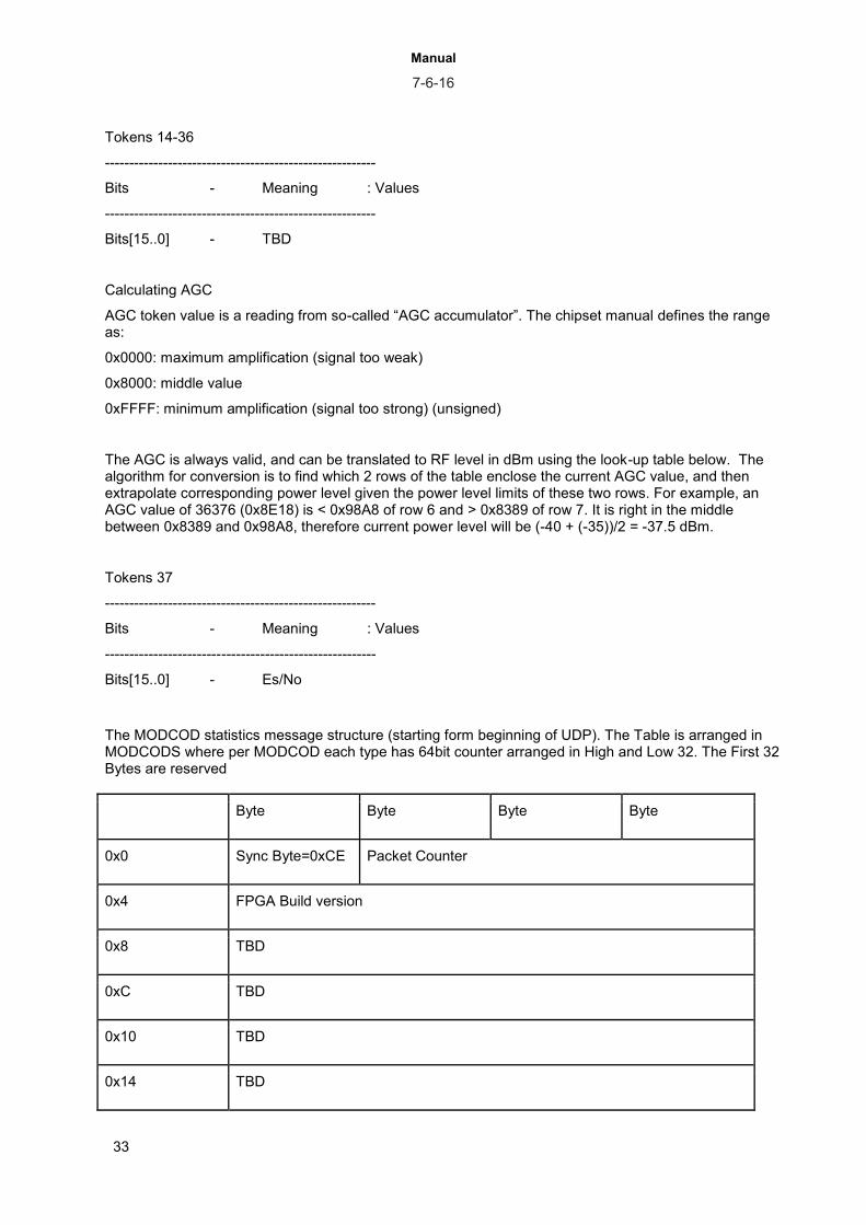
Tokens 14-36
--------------------------------------------------------
Bits - Meaning : Values
--------------------------------------------------------
Bits[15..0] - TBD
Calculating AGC
AGC token value is a reading from so-called “AGC accumulator”. The chipset manual defines the range as:
0x0000: maximum amplification (signal too weak)
0x8000: middle value
0xFFFF: minimum amplification (signal too strong) (unsigned)
The AGC is always valid, and can be translated to RF level in dBm using the look-up table below. The algorithm for conversion is to find which 2 rows of the table enclose the current AGC value, and then extrapolate corresponding power level given the power level limits of these two rows. For example, an AGC value of 36376 (0x8E18) is < 0x98A8 of row 6 and > 0x8389 of row 7. It is right in the middle between 0x8389 and 0x98A8, therefore current power level will be (-40 + (-35))/2 = -37.5 dBm.
Tokens 37
--------------------------------------------------------
Bits - Meaning : Values
--------------------------------------------------------
Bits[15..0] - Es/No
The MODCOD statistics message structure (starting form beginning of UDP). The Table is arranged in MODCODS where per MODCOD each type has 64bit counter arranged in High and Low 32. The First 32 Bytes are reserved
Byte Byte Byte Byte
0x0 Sync Byte=0xCE Packet Counter
0x4 FPGA Build version
0x8 TBD
0xC TBD
0x10 TBD
0x14 TBD

Manual 7-6-16
34
0x18 TBD
0x1C TBD
0x20 TBD
0x24 TBD
0x28 ModCod 1 Type '00' Counter 32MSBits
ModCod 1 Type '00' Counter 32LSBits
ModCod 1 Type '01' Counter 32MSBits
ModCod 1 Type '01' Counter 32LSBits
ModCod 1 Type '10' Counter 32MSBits
ModCod 1 Type '10' Counter 32LSBits
ModCod 1 Type '11' Counter 32MSBits
ModCod 1 Type '11' Counter 32LSBits
ModCod 2 Type '00' Counter 32MSBits
ModCod 2 Type '00' Counter 32LSBits
…..
ModCod 28 Type '11' Counter 32LSBits

Manual 7-6-16
35
16. Validating the configuration Validating the configuration involves the following steps
● Local Network
○ ping to the Management and traffic port
● RF ○ Use the receiver status menu to verify Es/No, Power level, etc. ○ Verify receiver status in the remote site
● Ping over Satellite
○ Ping form PC in one end to a PC in the other end. Use the statistics of the Tx to verify packets are getting to the Tx and the Rx statistics in the remote side to verify packets are transmitted over satellite
16.1. Rx Status menu
The device sample the status of the demodulator, randomly, every 3 seconds. In case of a channel that is not full with payload and has many Dummy packets - the MODCOD may be displayed - Dummy PLFrames.
RX Status 1, Configuration 1
============================
1. Tuner Status Locked
2. Demodulator Status Locked
3. Transport Status Locked
4. Demodulator Frequency Offset -54 KHz
5. Demodulator Es/N0 22.9 dB
6. Signal Input Level -52.0 dBm
7. Demodulator BER 0.00 e-7
8. Bad Frame Count 35
9. Bad Packet Count 0
A. Demodulator Link Margin 9.5 dB
B. Modulation Order and Code Rate DVB-S2 16APSK 9/10
C. Link Adaptation ACM
D. Pilots On
E. Frame Type Normal
F. Roll Off 20%
G. FPGA Loaded
16.2. Tx Status Menu
Power State ON
Center Frequency 1700.000 MHz
Input Bitrate 203557.192 Kbps - This is the input bit rate to the Modulator
Roll-off 15%

Manual 7-6-16
36
17. Images management The products internal Flash (nonvolatile) memory stores 2 images of software, 2 images of firmware
and an image of the Boot Loader. The images can be managed to provide field upgrade of the product. For each type of image (Software or FPGA) there is an active image and non-active. The active
image is the one to be used in next cold reboot or power cycle. Images are uploaded using TFTP protocol. When loading a new image, it is replacing the non-active
image.
The SW upgrade may delete the current configuration. Please make sure you retrieve and save the configuration from the product prior upgrading it
When upgrading to new Bootloader the recommended order is as follows: ● Upgrade the application and reboot the product with the new Application that support bootloader
upgrade ● Upload new BootLoader, Activate it and reboot with new Boot loader ● Upload FPGA file and Application again
Telnet and TFTP share the same resources. It is recommended that during the TFTP session, Telnet will be disconnected.
the active SW and FW are displayed on the top menu. To find out the Bootloader version one need to perform a cold reboot.
All the image management menus are under system menu. All menus has the same structure: a. TFTP server IP address - when configuring the TFTP server, it is recommended to ping
from the server to the Management interface of the unit. The products have single server that is used to all type of images
b. File name - File name of the image, as it appears in the TFTP directory, including the extension
c. Show installed versions - where one can see the 2 images saved on the flash memory of the product. From this menu one select the active image to be used after next reboot
d. Start the upload procedure - This start the TFTP download process. Prior to the TFTP the software will erase the non-active version. This process can take up to 40 sec.
Below is a list of the steps to load a new image.
1. Make sure the management IP address of the device is in the correct sub-net ( meaning it can access the TFTP server)
2. Ping from the TFTP server to the device 3. verify there are no firewall on the way between the product to the TFTP server 4. Set the TFTP server IP 5. Set the File name - when using copy - Paste, verify the name is pasted correctly,
including the extension. 6. Start the TFTP process. Verify the download counter is increasing. 7. After completion of the TFTP process, the user interface returns to the main menu. 8. Return to the relevant menu to select the new image to be active on next reboot. 9. Preform cold reboot (from system menu) at the propriety time 10. verify the device is up again with the new images
Image download does not work - please check
1. Ping form PC with TFTP server to device 2. check Management IP 3. check image file name 4. check the log file of the TFTP server 5. PC running TFTP server has firewall blocking incoming requests?
Manual 7-6-16
37
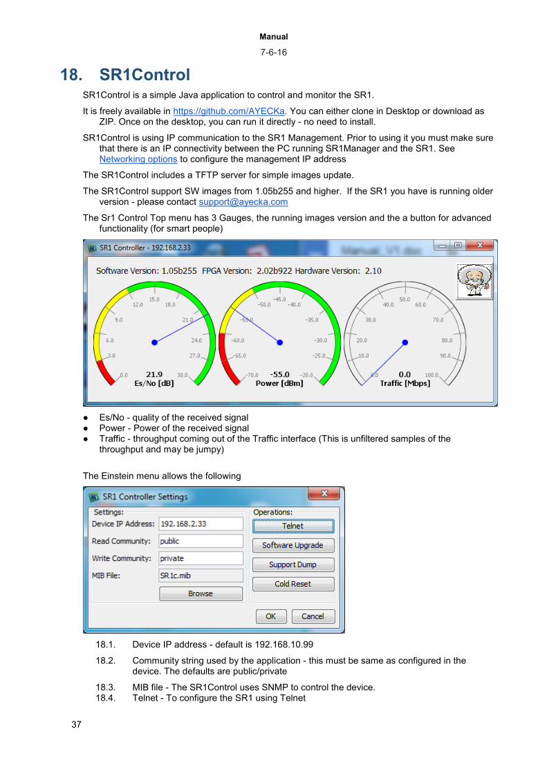
18. SR1Control SR1Control is a simple Java application to control and monitor the SR1.
It is freely available in https://github.com/AYECKa. You can either clone in Desktop or download as ZIP. Once on the desktop, you can run it directly - no need to install.
SR1Control is using IP communication to the SR1 Management. Prior to using it you must make sure that there is an IP connectivity between the PC running SR1Manager and the SR1. See Networking options to configure the management IP address
The SR1Control includes a TFTP server for simple images update.
The SR1Control support SW images from 1.05b255 and higher. If the SR1 you have is running older version - please contact [email protected]
The Sr1 Control Top menu has 3 Gauges, the running images version and the a button for advanced functionality (for smart people)
● Es/No - quality of the received signal ● Power - Power of the received signal ● Traffic - throughput coming out of the Traffic interface (This is unfiltered samples of the
throughput and may be jumpy)
The Einstein menu allows the following
18.1. Device IP address - default is 192.168.10.99
18.2. Community string used by the application - this must be same as configured in the device. The defaults are public/private
18.3. MIB file - The SR1Control uses SNMP to control the device. 18.4. Telnet - To configure the SR1 using Telnet

Manual 7-6-16
38
18.5. Support Dump - Generate a text file with all the technical information about the device. If you need support from Ayecka, it is best to send us this file. File is located in the same directory of the application - SupportDump.txt
18.6. Cold reset - to reboot the SR1 18.7. Software Upgrade - to upgrade the SW and FW images.
The Browse button list all the images files in the /TFTP sub-directory.
To upgrade an image:
● Retrieve the new image - by downloading or in email or any other way.. ● Select the image ● Press upgrade button ● the following screen should appear for about 30 sec. During this time the main screen will
show that the unit is unlocked
● Once upgrade is completed you will see the screen below and the main screen updated