Embed Size (px)
Citation preview
Linear Motion andAssembly Technologies ServicePneumaticsHydraulics
Electric Drives and Controls
Axial Piston Variable PumpA11VO
Data sheet
Series 1Size NG40 to 260Nominal pressure 350 barMaximum pressure 400 barOpen circuit
FeaturesVariable axial piston pump of swashplate design for hydrosta- –tic drives in open circuit hydraulic system.
Designed primarily for use in mobile applications. –
The pump operates under self-priming conditions, with tank –pressurization, or with an optional built-in charge pump (impeller).
A comprehensive range of control options is available –matching any application requirement.
Power control option is externally adjustable, even when the –pump is running.
The through drive is suitable for adding gear pumps and axial –piston pumps up to the same, i.e. 100% through drive.
The output flow is proportional to the drive speed and –infinitely variable between qV max and qV min = 0.
RE 92500/10.09 1/64Replaces: 06.09
ContentsOrdering Code / Standard Program 2
Technical Data 5
LR – Power Control 9
DR – Pressure Control 20
HD – Hydraulic Control, Pilot-Pressure Related 24
EP – Electric Control with Proportional Solenoid 26
Dimensions, Size 40 28
Dimensions, Size 60 32
Dimensions, Size 75 36
Dimensions, Size 95 40
Dimensions, Size 130/145 44
Dimensions, Size 190 48
Dimensions, Size 260 52
Through Drive Dimensions 56
Overview of Attachments for A11V(L)O 58
Combination Pumps A11VO + A11VO 58
Swivel Angle Indicator 59
Connector for Solenoids 60
Installation Notes 61
General Notes 64
2/64 Bosch Rexroth AG A11VO Series 1 RE 92500/10.09
Ordering Code / Standard Program
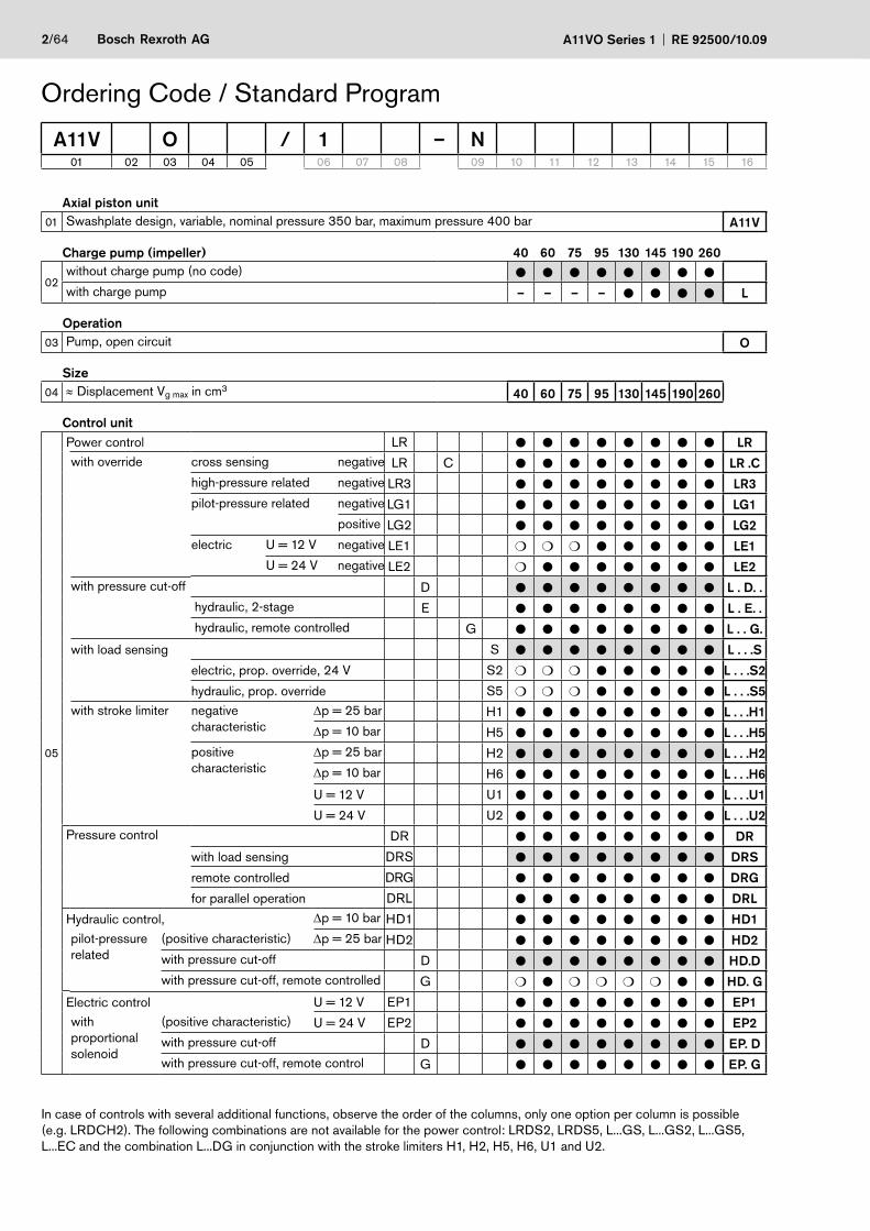
Axial piston unit01 Swashplate design, variable, nominal pressure 350 bar, maximum pressure 400 bar A11V
Charge pump (impeller) 40 60 75 95 130 145 190 260
02without charge pump (no code) ● ● ● ● ● ● ● ●
with charge pump – – – – ● ● ● ● L
Operation03 Pump, open circuit O
Size04 ≈ Displacement Vg max in cm3 40 60 75 95 130 145 190 260
Control unit
05
Power control LR ● ● ● ● ● ● ● ● LRwith override cross sensing negative LR C ● ● ● ● ● ● ● ● LR .C
high-pressure related negative LR3 ● ● ● ● ● ● ● ● LR3pilot-pressure related negative LG1 ● ● ● ● ● ● ● ● LG1
positive LG2 ● ● ● ● ● ● ● ● LG2electric U = 12 V negative LE1 ❍ ❍ ❍ ● ● ● ● ● LE1
U = 24 V negative LE2 ❍ ● ● ● ● ● ● ● LE2with pressure cut-off D ● ● ● ● ● ● ● ● L . D. .
hydraulic, 2-stage E ● ● ● ● ● ● ● ● L . E. .hydraulic, remote controlled G ● ● ● ● ● ● ● ● L . . G.
with load sensing S ● ● ● ● ● ● ● ● L . . .S
electric, prop. override, 24 V S2 ❍ ❍ ❍ ● ● ● ● ● L . . .S2
hydraulic, prop. override S5 ❍ ❍ ❍ ● ● ● ● ● L . . .S5with stroke limiter negative
characteristicΔp = 25 bar H1 ● ● ● ● ● ● ● ● L . . .H1Δp = 10 bar H5 ● ● ● ● ● ● ● ● L . . .H5
positive characteristic
Δp = 25 bar H2 ● ● ● ● ● ● ● ● L . . .H2Δp = 10 bar H6 ● ● ● ● ● ● ● ● L . . .H6
U = 12 V U1 ● ● ● ● ● ● ● ● L . . .U1
U = 24 V U2 ● ● ● ● ● ● ● ● L . . .U2Pressure control DR ● ● ● ● ● ● ● ● DR
with load sensing DRS ● ● ● ● ● ● ● ● DRS
remote controlled DRG ● ● ● ● ● ● ● ● DRG
for parallel operation DRL ● ● ● ● ● ● ● ● DRL
Hydraulic control, Δp = 10 bar HD1 ● ● ● ● ● ● ● ● HD1pilot-pressure related
(positive characteristic) Δp = 25 bar HD2 ● ● ● ● ● ● ● ● HD2with pressure cut-off D ● ● ● ● ● ● ● ● HD.Dwith pressure cut-off, remote controlled G ❍ ● ❍ ❍ ❍ ❍ ● ● HD. G
Electric control U = 12 V EP1 ● ● ● ● ● ● ● ● EP1with proportional solenoid
(positive characteristic) U = 24 V EP2 ● ● ● ● ● ● ● ● EP2with pressure cut-off D ● ● ● ● ● ● ● ● EP. Dwith pressure cut-off, remote control G ● ● ● ● ● ● ● ● EP. G
A11V O / 1 – N01 02 03 04 05 06 07 08 09 10 11 12 13 14 15 16
In case of controls with several additional functions, observe the order of the columns, only one option per column is possible (e.g. LRDCH2). The following combinations are not available for the power control: LRDS2, LRDS5, L...GS, L...GS2, L...GS5,L...EC and the combination L...DG in conjunction with the stroke limiters H1, H2, H5, H6, U1 and U2.
RE 92500/10.09 A11VO Series 1 Bosch Rexroth AG 3/64
Ordering Code / Standard Program
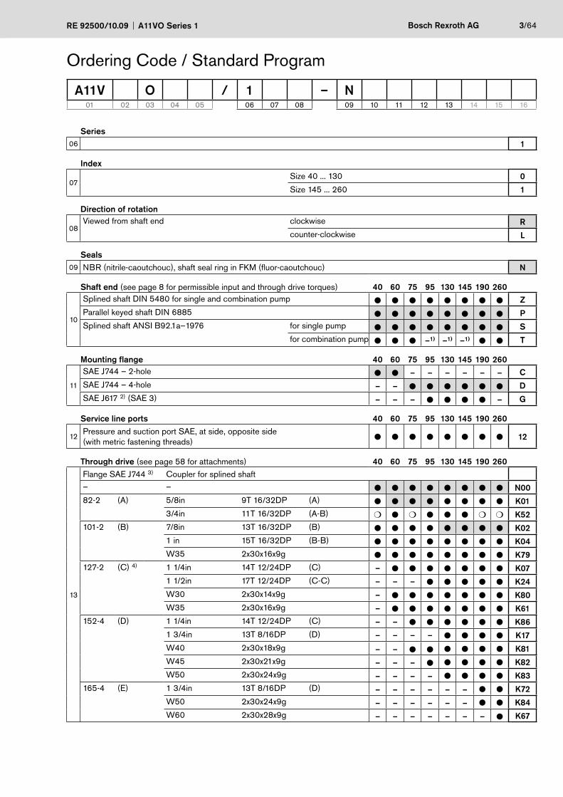
Series06 1
Index
07Size 40 ... 130 0
Size 145 ... 260 1
Direction of rotation
08Viewed from shaft end clockwise R
counter-clockwise L
Seals09 NBR (nitrile-caoutchouc), shaft seal ring in FKM (fluor-caoutchouc) N
Shaft end (see page 8 for permissible input and through drive torques) 40 60 75 95 130 145 190 260
10
Splined shaft DIN 5480 for single and combination pump ● ● ● ● ● ● ● ● ZParallel keyed shaft DIN 6885 ● ● ● ● ● ● ● ● PSplined shaft ANSI B92.1a–1976 for single pump ● ● ● ● ● ● ● ● S
for combination pump ● ● ● –1) –1) –1) ● ● T
Mounting flange 40 60 75 95 130 145 190 260
11
SAE J744 – 2-hole ● ● – – – – – – CSAE J744 – 4-hole – – ● ● ● ● ● ● DSAE J617 2) (SAE 3) – – – ● ● ● ● – G
Service line ports 40 60 75 95 130 145 190 260
12Pressure and suction port SAE, at side, opposite side(with metric fastening threads) ● ● ● ● ● ● ● ● 12
Through drive (see page 58 for attachments) 40 60 75 95 130 145 190 260
13
Flange SAE J744 3) Coupler for splined shaft– – ● ● ● ● ● ● ● ● N0082-2 (A) 5/8in 9T 16/32DP (A) ● ● ● ● ● ● ● ● K01
3/4in 11T 16/32DP (A-B) ❍ ● ❍ ● ● ● ❍ ❍ K52101-2 (B) 7/8in 13T 16/32DP (B) ● ● ● ● ● ● ● ● K02
1 in 15T 16/32DP (B-B) ● ● ● ● ● ● ● ● K04W35 2x30x16x9g ● ● ● ● ● ● ● ● K79
127-2 (C) 4) 1 1/4in 14T 12/24DP (C) – ● ● ● ● ● ● ● K071 1/2in 17T 12/24DP (C-C) – – – ● ● ● ● ● K24W30 2x30x14x9g – ● ● ● ● ● ● ● K80W35 2x30x16x9g – ● ● ● ● ● ● ● K61
152-4 (D) 1 1/4in 14T 12/24DP (C) – – ● ● ● ● ● ● K861 3/4in 13T 8/16DP (D) – – – – ● ● ● ● K17W40 2x30x18x9g – – ● ● ● ● ● ● K81W45 2x30x21x9g – – – ● ● ● ● ● K82W50 2x30x24x9g – – – – ● ● ● ● K83
165-4 (E) 1 3/4in 13T 8/16DP (D) – – – – – – ● ● K72W50 2x30x24x9g – – – – – – ● ● K84W60 2x30x28x9g – – – – – – – ● K67
A11V O / 1 – N01 02 03 04 05 06 07 08 09 10 11 12 13 14 15 16
4/64 Bosch Rexroth AG A11VO Series 1 RE 92500/10.09
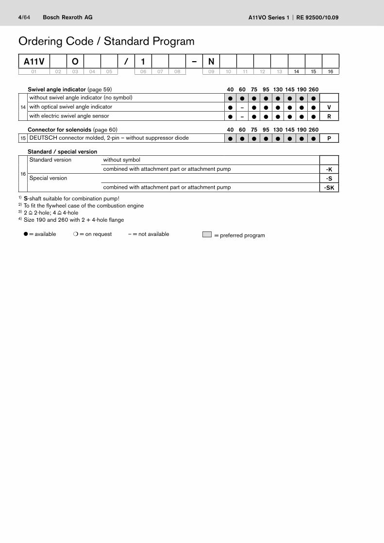
Swivel angle indicator (page 59) 40 60 75 95 130 145 190 260
14
without swivel angle indicator (no symbol) ● ● ● ● ● ● ● ●
with optical swivel angle indicator ● – ● ● ● ● ● ● Vwith electric swivel angle sensor ● – ● ● ● ● ● ● R
Connector for solenoids (page 60) 40 60 75 95 130 145 190 26015 DEUTSCH connector molded, 2-pin – without suppressor diode ● ● ● ● ● ● ● ● P
Standard / special version
16
Standard version without symbol
combined with attachment part or attachment pump -KSpecial version -S
combined with attachment part or attachment pump -SK
1) S-shaft suitable for combination pump!2) To fit the flywheel case of the combustion engine3) 2 2-hole; 4 4-hole4) Size 190 and 260 with 2 + 4-hole flange
= available ❍ = on request – = not available = preferred program
A11V O / 1 – N01 02 03 04 05 06 07 08 09 10 11 12 13 14 15 16
Ordering Code / Standard Program
RE 92500/10.09 A11VO Series 1 Bosch Rexroth AG 5/64
Technical DataHydraulic fluidBefore starting project planning, please refer to our data sheets RE 90220 (mineral oil), RE 90221 (environmentally acceptable hydraulic fluids) and RE 90223 (HF hydraulic fluids) for detailed information regarding the choi-ce of hydraulic fluid and operating conditions.
The variable pump A11VO is not suitable for operating with HFA, HFB and HFC. If HFD or environmentally acceptab-le hydraulic fluids are being used, the limitations regarding technical data and seals mentioned in RE 90221 and RE 90223 must be observed.
When ordering, please indicate the used hydraulic fluid.
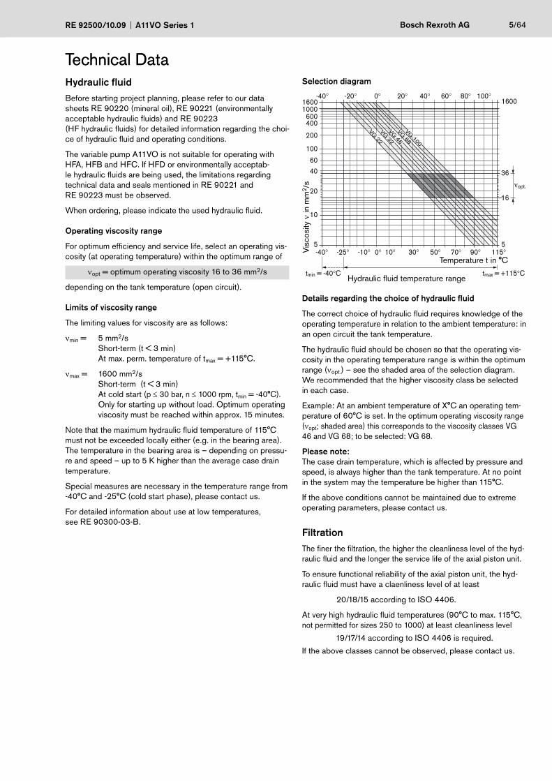
Operating viscosity range
For optimum efficiency and service life, select an operating vis-cosity (at operating temperature) within the optimum range of
νopt = optimum operating viscosity 16 to 36 mm2/s
depending on the tank temperature (open circuit).
Limits of viscosity range
The limiting values for viscosity are as follows:
νmin = 5 mm2/s Short-term (t < 3 min) At max. perm. temperature of tmax = +115°C.
νmax = 1600 mm2/s Short-term (t < 3 min) At cold start (p ≤ 30 bar, n ≤ 1000 rpm, tmin = -40°C). Only for starting up without load. Optimum operating
viscosity must be reached within approx. 15 minutes.
Note that the maximum hydraulic fluid temperature of 115°C must not be exceeded locally either (e.g. in the bearing area). The temperature in the bearing area is – depending on pressu-re and speed – up to 5 K higher than the average case drain temperature.
Special measures are necessary in the temperature range from -40°C and -25°C (cold start phase) , please contact us.
For detailed information about use at low temperatures, see RE 90300-03-B.
Selection diagram
tmin = -40°C tmax = +115°C
-40° -25° -10° 10° 30° 50° 90° 115°70°0°5
10
4060
20
100
200
400600
10001600
-40° 0° 20° 40° 60° 80° 100° -20°1600
νopt.
16
36VG
22VG
32VG
46VG
68VG
100
5
Hydraulic fluid temperature range
Temperature t in °C
Visc
osity
ν in
mm
2 /s
Details regarding the choice of hydraulic fluid
The correct choice of hydraulic fluid requires knowledge of the operating temperature in relation to the ambient temperature: in an open circuit the tank temperature.
The hydraulic fluid should be chosen so that the operating vis-cosity in the operating temperature range is within the optimum range (νopt.) – see the shaded area of the selection diagram. We recommended that the higher viscosity class be selected in each case.
Example: At an ambient temperature of X°C an operating tem-perature of 60°C is set. In the optimum operating viscosity range (νopt; shaded area) this corresponds to the viscosity classes VG 46 and VG 68; to be selected: VG 68.
Please note: The case drain temperature, which is affected by pressure and speed, is always higher than the tank temperature. At no point in the system may the temperature be higher than 115°C.
If the above conditions cannot be maintained due to extreme operating parameters, please contact us.
FiltrationThe finer the filtration, the higher the cleanliness level of the hyd-raulic fluid and the longer the service life of the axial piston unit.
To ensure functional reliability of the axial piston unit, the hyd-raulic fluid must have a claenliness level of at least
20/18/15 according to ISO 4406.
At very high hydraulic fluid temperatures (90°C to max. 115°C, not permitted for sizes 250 to 1000) at least cleanliness level
19/17/14 according to ISO 4406 is required.
If the above classes cannot be observed, please contact us.
Technical Data
6/64 Bosch Rexroth AG A11VO Series 1 RE 92500/10.09
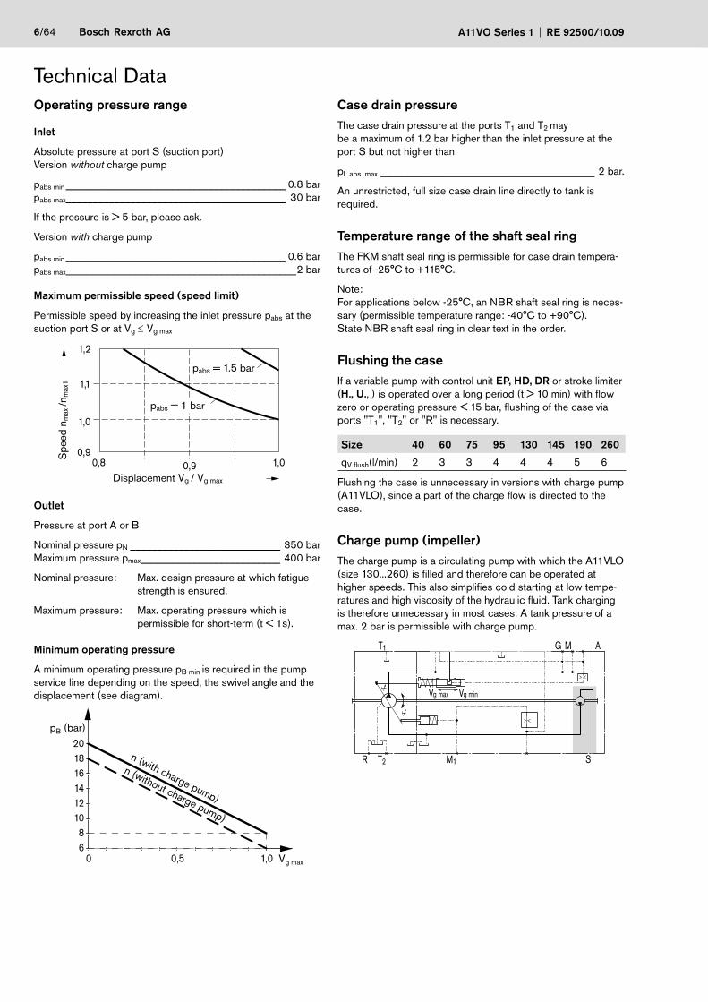
Technical DataOperating pressure range
Inlet
Absolute pressure at port S (suction port)Version without charge pump
pabs min _________________________________________ 0.8 barpabs max _________________________________________ 30 bar
If the pressure is > 5 bar, please ask.
Version with charge pump
pabs min _________________________________________ 0.6 barpabs max ___________________________________________2 bar
Maximum permissible speed (speed limit)
Permissible speed by increasing the inlet pressure pabs at the suction port S or at Vg ≤ Vg max
1,2
0,8 0,9 1,00,9
1,0
1,1
pabs = 1 bar
Spe
ed n
max
/nm
ax1
Displacement Vg / Vg max
pabs = 1.5 bar
Outlet
Pressure at port A or B
Nominal pressure pN ____________________________ 350 barMaximum pressure pmax __________________________ 400 bar
Nominal pressure: Max. design pressure at which fatigue strength is ensured.
Maximum pressure: Max. operating pressure which is permissible for short-term (t < 1s).
Minimum operating pressure
A minimum operating pressure pB min is required in the pump service line depending on the speed, the swivel angle and the displacement (see diagram).
0,50 1,0
20181614121086
pB (bar)
Vg max
n (with charge pump)
n (without charge pump)
Case drain pressureThe case drain pressure at the ports T1 and T2 maybe a maximum of 1.2 bar higher than the inlet pressure at the port S but not higher than
pL abs. max ________________________________________ 2 bar.
An unrestricted, full size case drain line directly to tank is required.
Temperature range of the shaft seal ringThe FKM shaft seal ring is permissible for case drain tempera-tures of -25°C to +115°C.
Note:For applications below -25°C, an NBR shaft seal ring is neces-sary (permissible temperature range: -40°C to +90°C). State NBR shaft seal ring in clear text in the order.
Flushing the caseIf a variable pump with control unit EP, HD, DR or stroke limiter (H., U., ) is operated over a long period (t > 10 min) with flow zero or operating pressure < 15 bar, flushing of the case via ports "T1", "T2" or "R" is necessary.
Size 40 60 75 95 130 145 190 260
qV flush(l/min) 2 3 3 4 4 4 5 6
Flushing the case is unnecessary in versions with charge pump (A11VLO), since a part of the charge flow is directed to the case.
Charge pump (impeller)The charge pump is a circulating pump with which the A11VLO (size 130...260) is filled and therefore can be operated at higher speeds. This also simplifies cold starting at low tempe-ratures and high viscosity of the hydraulic fluid. Tank charging is therefore unnecessary in most cases. A tank pressure of a max. 2 bar is permissible with charge pump.
T1
T2R
g ming max VV
M1 S
AMG
RE 92500/10.09 A11VO Series 1 Bosch Rexroth AG 7/64
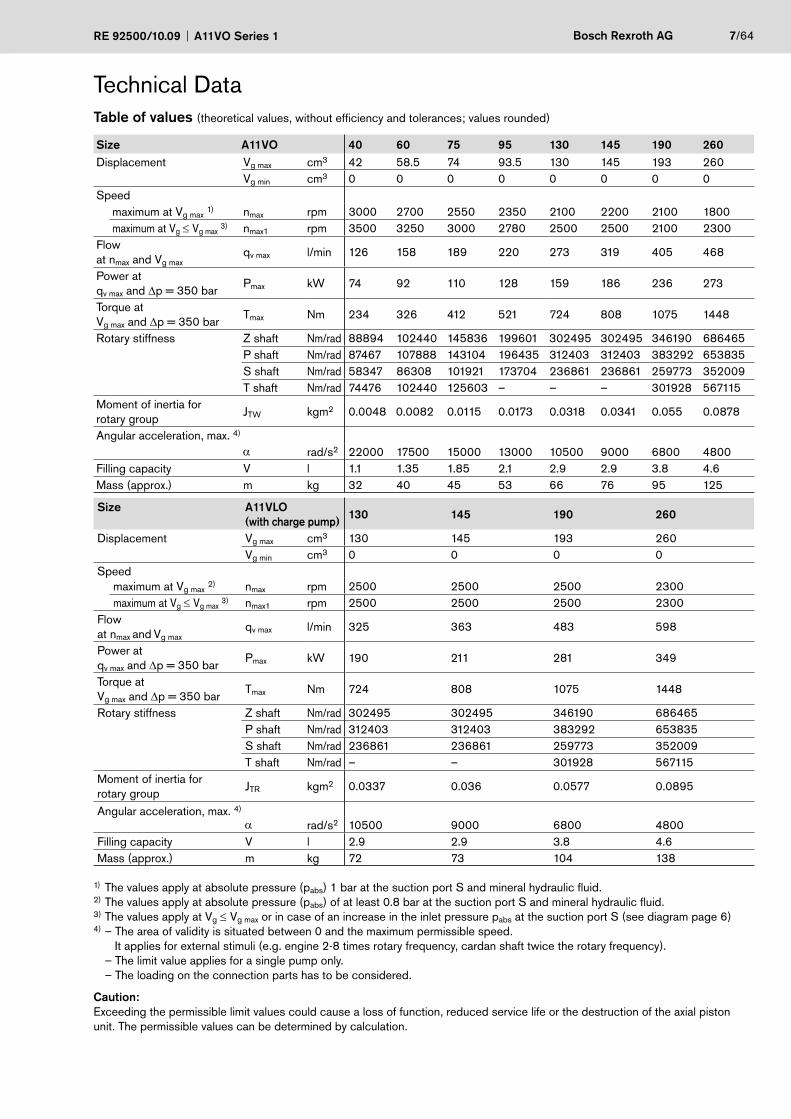
Table of values (theoretical values, without efficiency and tolerances; values rounded)
Size A11VO 40 60 75 95 130 145 190 260Displacement Vg max cm3 42 58.5 74 93.5 130 145 193 260
Vg min cm3 0 0 0 0 0 0 0 0Speed
maximum at Vg max 1) nmax rpm 3000 2700 2550 2350 2100 2200 2100 1800maximum at Vg ≤ Vg max 3) nmax1 rpm 3500 3250 3000 2780 2500 2500 2100 2300
Flowat nmax and Vg max
qv max l/min 126 158 189 220 273 319 405 468
Power at qv max and Δp = 350 bar
Pmax kW 74 92 110 128 159 186 236 273
Torque at Vg max and Δp = 350 bar
Tmax Nm 234 326 412 521 724 808 1075 1448
Rotary stiffness Z shaft Nm/rad 88894 102440 145836 199601 302495 302495 346190 686465P shaft Nm/rad 87467 107888 143104 196435 312403 312403 383292 653835S shaft Nm/rad 58347 86308 101921 173704 236861 236861 259773 352009T shaft Nm/rad 74476 102440 125603 – – – 301928 567115
Moment of inertia forrotary group
JTW kgm2 0.0048 0.0082 0.0115 0.0173 0.0318 0.0341 0.055 0.0878
Angular acceleration, max. 4)
α rad/s2 22000 17500 15000 13000 10500 9000 6800 4800Filling capacity V l 1.1 1.35 1.85 2.1 2.9 2.9 3.8 4.6Mass (approx.) m kg 32 40 45 53 66 76 95 125
Size A11VLO(with charge pump)
130 145 190 260
Displacement Vg max cm3 130 145 193 260Vg min cm3 0 0 0 0
Speedmaximum at Vg max 2) nmax rpm 2500 2500 2500 2300maximum at Vg ≤ Vg max 3) nmax1 rpm 2500 2500 2500 2300
Flowat nmax and Vg max
qv max l/min 325 363 483 598
Power at qv max and Δp = 350 bar
Pmax kW 190 211 281 349
Torque at Vg max and Δp = 350 bar
Tmax Nm 724 808 1075 1448
Rotary stiffness Z shaft Nm/rad 302495 302495 346190 686465P shaft Nm/rad 312403 312403 383292 653835S shaft Nm/rad 236861 236861 259773 352009T shaft Nm/rad – – 301928 567115
Moment of inertia forrotary group
JTR kgm2 0.0337 0.036 0.0577 0.0895
Angular acceleration, max. 4)
α rad/s2 10500 9000 6800 4800Filling capacity V l 2.9 2.9 3.8 4.6Mass (approx.) m kg 72 73 104 138
1) The values apply at absolute pressure (pabs) 1 bar at the suction port S and mineral hydraulic fluid.2) The values apply at absolute pressure (pabs) of at least 0.8 bar at the suction port S and mineral hydraulic fluid.3) The values apply at Vg ≤ Vg max or in case of an increase in the inlet pressure pabs at the suction port S (see diagram page 6)4) – The area of validity is situated between 0 and the maximum permissible speed.
It applies for external stimuli (e.g. engine 2-8 times rotary frequency, cardan shaft twice the rotary frequency). – The limit value applies for a single pump only. – The loading on the connection parts has to be considered.
Caution:Exceeding the permissible limit values could cause a loss of function, reduced service life or the destruction of the axial piston unit. The permissible values can be determined by calculation.
Technical Data
8/64 Bosch Rexroth AG A11VO Series 1 RE 92500/10.09
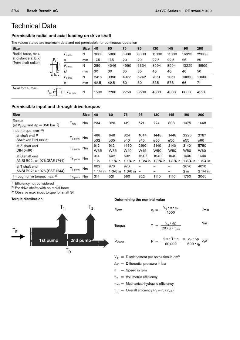
Technical DataPermissible radial and axial loading on drive shaftThe values stated are maximum data and not permissible for continuous operation
Size Size 40 60 75 95 130 145 190 260Radial force, max.at distance a, b, c(from shaft collar)
a, b, c
Fq
Fq max N 3600 5000 6300 8000 11000 11000 16925 22000
a mm 17.5 17.5 20 20 22.5 22.5 26 29
Fq max N 2891 4046 4950 6334 8594 8594 13225 16809
B mm 30 30 35 35 40 40 46 50
Fq max N 2416 3398 4077 5242 7051 7051 10850 13600
c mm 42.5 42.5 50 50 57.5 57.5 66 71Axial force, max. -
+Fax ± Fax max N 1500 2200 2750 3500 4800 4800 6000 4150
Permissible input and through drive torques
Size Size 40 60 75 95 130 145 190 260
Torque (at Vg max and Δp = 350 bar 1))
Tmax Nm 234 326 412 521 724 808 1075 1448
Input torque, max. 2)at shaft end PShaft key DIN 6885
TE perm. Nm468 648 824 1044 1448 1448 2226 2787ø32 ø35 ø40 ø45 ø50 ø50 ø55 ø60
at Z shaft end DIN 5480
TE perm. Nm912 912 1460 2190 3140 3140 3140 5780W35 W35 W40 W45 W50 W50 W50 W60
at S shaft endANSI B92.1a-1976 (SAE J744)
TE perm. Nm314 602 602 1640 1640 1640 1640 16401 in 1 1/4 in 1 1/4 in 1 3/4 in 1 3/4 in 1 3/4 in 1 3/4 in 1 3/4 in
at T shaft endANSI B92.1a-1976 (SAE J744)
TE perm. Nm602 970 970 — — – 2670 40701 1/4 in 1 3/8 in 1 3/8 in — — – 2 in 2 1/4 in
Through drive torque, max. 3) TD perm. Nm 314 521 660 822 1110 1110 1760 2065
1) Efficiency not considered2) For drive shafts with no radial force3) Observe max. input torque for shaft S!
Torque distribution
2. Pumpe1. Pumpe
TE
TD
T1 T2
1st pump 2nd pump
Determining the nominal value
Flow qv =Vg • n • ηv l/min
1000
Torque T = Vg • Δp Nm
20 • π • ηmh
Power P =2 π • T • n = qv • Δp
kW60,000 600 • ηt
Vg = Displacement per revolution in cm3
Δp = Differential pressure in bar
n = Speed in rpm
ηv = Volumetric efficiency
ηmh = Mechanical-hydraulic efficiency
ηt = Overall efficiency (nt = nv • nmh)
RE 92500/10.09 A11VO Series 1 Bosch Rexroth AG 9/64
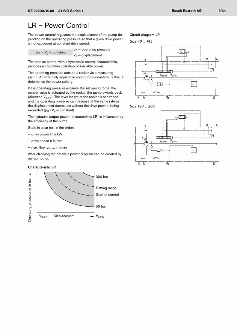
LR – Power ControlThe power control regulates the displacement of the pump de-pending on the operating pressure so that a given drive power is not exceeded at constant drive speed.
pB • Vg = constantpB = operating pressure
Vg = displacement
The precise control with a hyperbolic control characteristic, provides an optimum utilization of available power.
The operating pressure acts on a rocker via a measuring piston. An externally adjustable spring force counteracts this, it determines the power setting.
If the operating pressure exceeds the set spring force, the control valve is actuated by the rocker, the pump swivels back (direction Vg min). The lever length at the rocker is shortened and the operating pressure can increase at the same rate as the displacement decreases without the drive powers being exceeded (pB • Vg = constant).
The hydraulic output power (characteristic LR) is influenced by the efficiency of the pump.
State in clear text in the order:
drive power P in kW –
drive speed n in rpm –
max. flow q – V max in l/min
After clarifying the details a power diagram can be created by our computer.
Characteristic LR
320 bar
50 bar
Ope
ratin
g pr
essu
re p
B in
bar
DisplacementVg min Vg max
Setting range
Start of control
Circuit diagram LR
Size 40 ... 145
T1
T2R
g ming maxV V
M1 S
AM
Size 190 ... 260
g ming maxV V
M1 S
AMT1
T2R
10/64 Bosch Rexroth AG A11VO Series 1 RE 92500/10.09
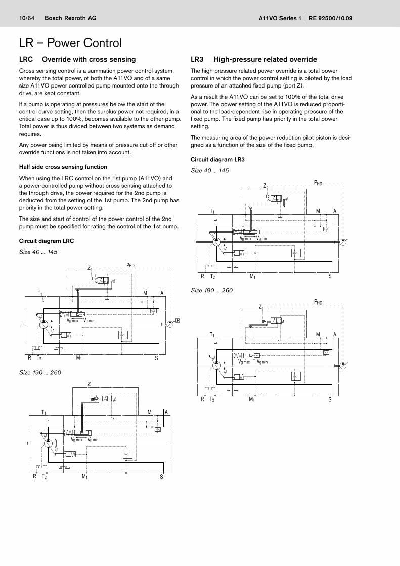
LRC Override with cross sensingCross sensing control is a summation power control system, whereby the total power, of both the A11VO and of a same size A11VO power controlled pump mounted onto the through drive, are kept constant.
If a pump is operating at pressures below the start of the control curve setting, then the surplus power not required, in a critical case up to 100%, becomes available to the other pump. Total power is thus divided between two systems as demand requires.
Any power being limited by means of pressure cut-off or other override functions is not taken into account.
Half side cross sensing function
When using the LRC control on the 1st pump (A11VO) and a power-controlled pump without cross sensing attached to the through drive, the power required for the 2nd pump is deducted from the setting of the 1st pump. The 2nd pump has priority in the total power setting.
The size and start of control of the power control of the 2nd pump must be specified for rating the control of the 1st pump.
Circuit diagram LRC
Size 40 ... 145
HDp
LR
Z
T1
T2R
g ming maxV V
M1 S
AM
Size 190 ... 260
Z
T1
T2R
g ming maxV V
M1 S
AM
LR – Power ControlLR3 High-pressure related overrideThe high-pressure related power override is a total power control in which the power control setting is piloted by the load pressure of an attached fixed pump (port Z).
As a result the A11VO can be set to 100% of the total drive power. The power setting of the A11VO is reduced proporti-onal to the load-dependent rise in operating pressure of the fixed pump. The fixed pump has priority in the total power setting.
The measuring area of the power reduction pilot piston is desi-gned as a function of the size of the fixed pump.
Circuit diagram LR3
Size 40 ... 145
T1
T2R
g ming maxV V
M1 S
AM
Z HDP
Size 190 ... 260
T1
T2R
g ming maxV V
M1 S
AM
ZHDP
RE 92500/10.09 A11VO Series 1 Bosch Rexroth AG 11/64
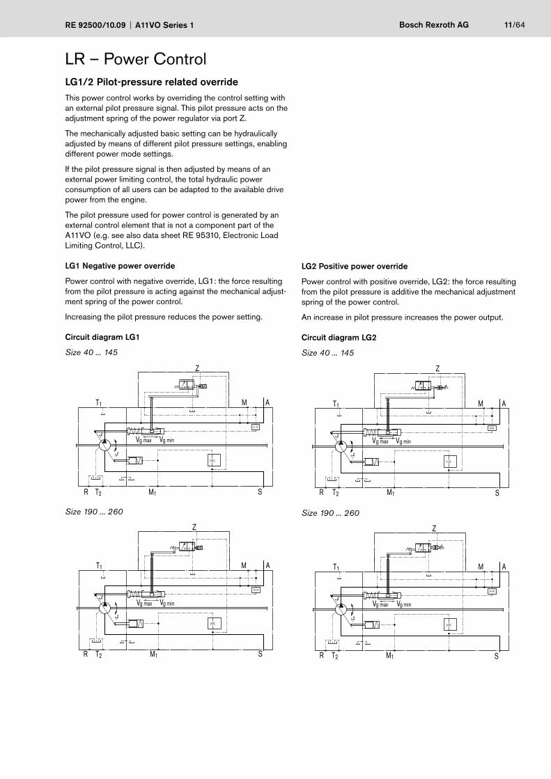
LR – Power ControlLG1/2 Pilot-pressure related overrideThis power control works by overriding the control setting with an external pilot pressure signal. This pilot pressure acts on the adjustment spring of the power regulator via port Z.
The mechanically adjusted basic setting can be hydraulically adjusted by means of different pilot pressure settings, enabling different power mode settings.
If the pilot pressure signal is then adjusted by means of an external power limiting control, the total hydraulic power consumption of all users can be adapted to the available drive power from the engine.
The pilot pressure used for power control is generated by an external control element that is not a component part of the A11VO (e.g. see also data sheet RE 95310, Electronic Load Limiting Control, LLC).
LG1 Negative power override
Power control with negative override, LG1: the force resulting from the pilot pressure is acting against the mechanical adjust-ment spring of the power control.
Increasing the pilot pressure reduces the power setting.
Circuit diagram LG1
Size 40 ... 145
T1
T2R
g ming maxV V
M1 S
AM
Z
Size 190 ... 260
Z
T1
T2R
g ming maxV V
M1 S
AM
LG2 Positive power override
Power control with positive override, LG2: the force resulting from the pilot pressure is additive the mechanical adjustment spring of the power control.
An increase in pilot pressure increases the power output.
Circuit diagram LG2
Size 40 ... 145
T1
T2R
g ming maxV V
M1 S
AM
Z
Size 190 ... 260
T1
T2R
g ming maxV V
M1 S
AM
Z
12/64 Bosch Rexroth AG A11VO Series 1 RE 92500/10.09
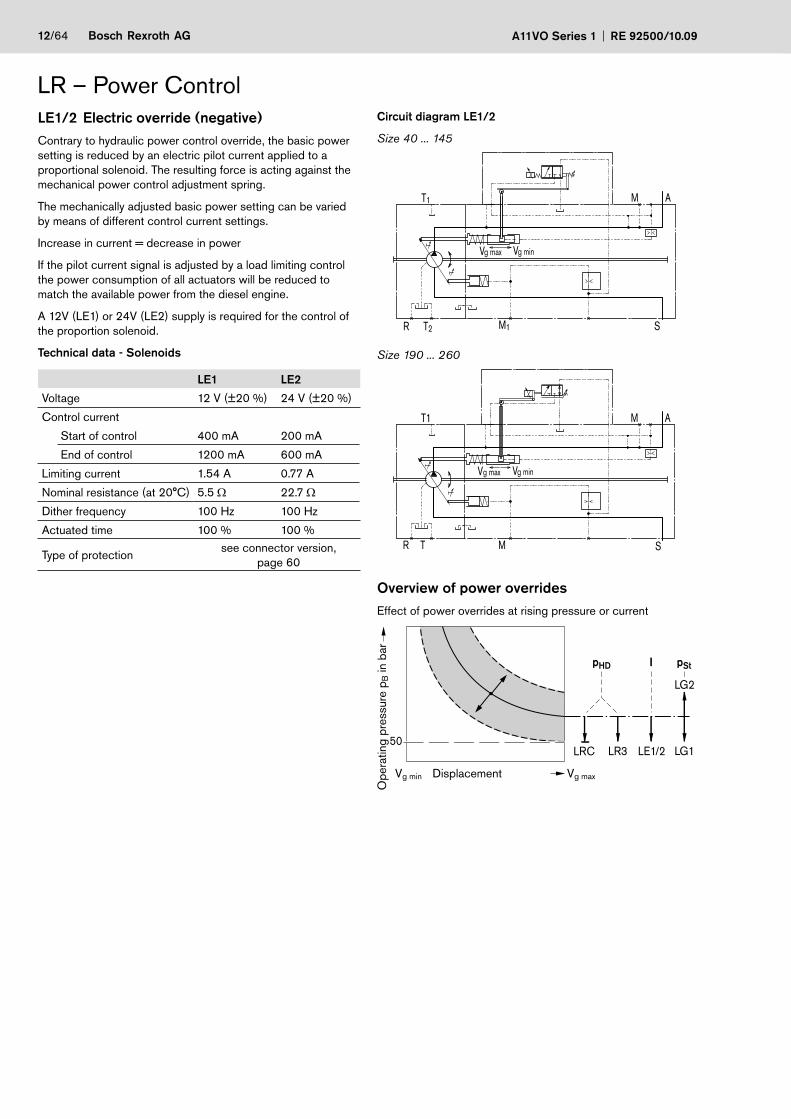
Circuit diagram LE1/2
Size 40 ... 145
T1
T2R
g ming maxV V
M1 S
AM
Size 190 ... 260
T1
TR
g ming maxV V
M S
AM
Overview of power overridesEffect of power overrides at rising pressure or current
LR3LRC
LG2
LG1LE1/2
pHD I pSt
50
Ope
ratin
g pr
essu
re p
B in
bar
DisplacementVg min Vg max
LE1/2 Electric override (negative)Contrary to hydraulic power control override, the basic power setting is reduced by an electric pilot current applied to a proportional solenoid. The resulting force is acting against the mechanical power control adjustment spring.
The mechanically adjusted basic power setting can be varied by means of different control current settings.
Increase in current = decrease in power
If the pilot current signal is adjusted by a load limiting control the power consumption of all actuators will be reduced to match the available power from the diesel engine.
A 12V (LE1) or 24V (LE2) supply is required for the control of the proportion solenoid.
Technical data - Solenoids
LE1 LE2
Voltage 12 V (±20 %) 24 V (±20 %)
Control current
Start of control 400 mA 200 mA
End of control 1200 mA 600 mA
Limiting current 1.54 A 0.77 A
Nominal resistance (at 20°C) 5.5 Ω 22.7 Ω
Dither frequency 100 Hz 100 Hz
Actuated time 100 % 100 %
Type of protectionsee connector version,
page 60
LR – Power Control
RE 92500/10.09 A11VO Series 1 Bosch Rexroth AG 13/64
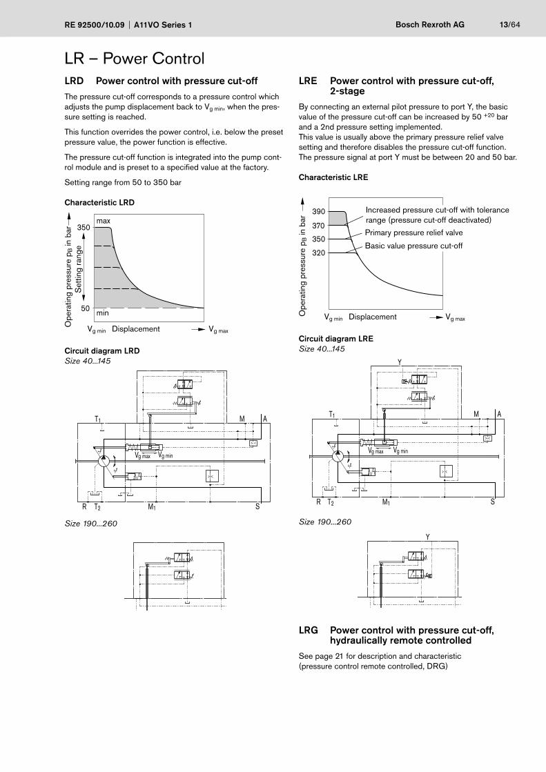
LRD Power control with pressure cut-offThe pressure cut-off corresponds to a pressure control which adjusts the pump displacement back to Vg min, when the pres-sure setting is reached.
This function overrides the power control, i.e. below the preset pressure value, the power function is effective.
The pressure cut-off function is integrated into the pump cont-rol module and is preset to a specified value at the factory.
Setting range from 50 to 350 bar
Characteristic LRD
350
50
Ope
ratin
g pr
essu
re p
B in
bar
DisplacementVg min Vg max
Set
ting
rang
e
max
min
Circuit diagram LRDSize 40...145
g ming max VV
M1 S
AMT1
T2R
Size 190...260
LR – Power ControlLRE Power control with pressure cut-off,
2-stageBy connecting an external pilot pressure to port Y, the basic value of the pressure cut-off can be increased by 50 +20 bar and a 2nd pressure setting implemented.This value is usually above the primary pressure relief valve setting and therefore disables the pressure cut-off function.The pressure signal at port Y must be between 20 and 50 bar.
Characteristic LRE
350
370
390
320
Ope
ratin
g pr
essu
re p
B in
bar
DisplacementVg min Vg max
Increased pressure cut-off with tolerancerange (pressure cut-off deactivated)
Primary pressure relief valve
Basic value pressure cut-off
Circuit diagram LRESize 40...145
T1
T2R
g ming max VV
M1 S
AM
Y
Size 190...260
Y
LRG Power control with pressure cut-off, hydraulically remote controlledSee page 21 for description and characteristic (pressure control remote controlled, DRG)
14/64 Bosch Rexroth AG A11VO Series 1 RE 92500/10.09
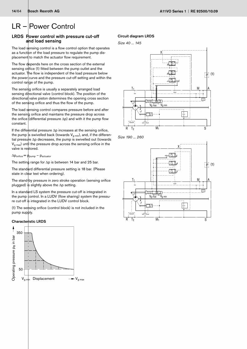
LRDS Power control with pressure cut-off and load sensing
The load sensing control is a flow control option that operates as a function of the load pressure to regulate the pump dis-placement to match the actuator flow requirement.
The flow depends here on the cross section of the external sensing orifice (1) fitted between the pump outlet and the actuator. The flow is independent of the load pressure below the power curve and the pressure cut-off setting and within the control range of the pump.
The sensing orifice is usually a separately arranged load sensing directional valve (control block). The position of the directional valve piston determines the opening cross section of the sensing orifice and thus the flow of the pump.
The load sensing control compares pressure before and after the sensing orifice and maintains the pressure drop across the orifice (differential pressure Δp) and with it the pump flow constant.
If the differential pressure Δp increases at the sensing orifice, the pump is swivelled back (towards Vg min), and, if the differen-tial pressure Δp decreases, the pump is swivelled out (towards Vg max) until the pressure drop across the sensing orifice in the valve is restored.
Δporifice = ppump – pactuator
The setting range for Δp is between 14 bar and 25 bar.
The standard differential pressure setting is 18 bar. (Please state in clear text when ordering).
The stand-by pressure in zero stroke operation (sensing orifice plugged) is slightly above the Δp setting.
In a standard LS system the pressure cut-off is integrated in the pump control. In a LUDV (flow sharing) system the pressu-re cut-off is integrated in the LUDV control block.
(1) The sensing orifice (control block) is not included in the pump supply.
Characteristic LRDS
350
50
Ope
ratin
g pr
essu
re p
B in
bar
DisplacementVg min Vg max
LR – Power ControlCircuit diagram LRDS
Size 40 ... 145
T1
T2R
g ming maxV V
M1 S
AM
X
Size 190 ... 260
T1
T2R
g ming maxV V
M1 S
AM
X
(1)
(1)
RE 92500/10.09 A11VO Series 1 Bosch Rexroth AG 15/64
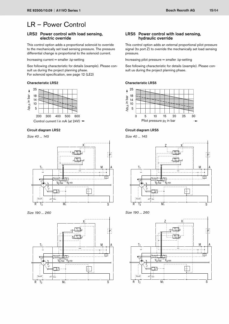
LRS2 Power control with load sensing, electric override
This control option adds a proportional solenoid to override to the mechanically set load sensing pressure. The pressure differential change is proportional to the solenoid current.
Increasing current = smaller Δp-setting
See following characteristic for details (example). Please con-sult us during the project planning phase.For solenoid specification, see page 12 (LE2)
Characteristic LRS2
ΔpLS
in b
ar
Control current I in mA (at 24V)
25
181410
5
200 300 400 500 600
Circuit diagram LRS2
Size 40 ... 145
T1
T2R
g ming maxV V
M1 S
AM
X
Size 190 ... 260
T1
T2R
g ming maxV V
M1 S
AM
X
LR – Power ControlLRS5 Power control with load sensing,
hydraulic overrideThis control option adds an external proportional pilot pressure signal (to port Z) to override the mechanically set load sensing pressure.
Increasing pilot pressure = smaller Δp-setting
See following characteristic for details (example). Please con-sult us during the project planning phase.
Characteristic LRS5
ΔpLS
in b
ar
Pilot pressure pZ in bar
25
181410
5
0 5 10 15 20 25 30
Circuit diagram LRS5
Size 40 ... 145
T1
T2R
g ming maxV V
M1 S
AM
Z X
Size 190 ... 260
T1
T2R
Vg minVg max
M1 S
AM
XZ
16/64 Bosch Rexroth AG A11VO Series 1 RE 92500/10.09
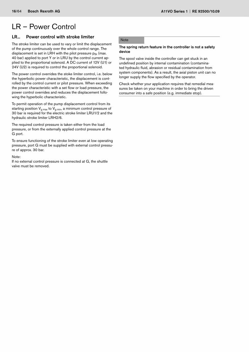
LR... Power control with stroke limiterThe stroke limiter can be used to vary or limit the displacement of the pump continuously over the whole control range. The displacement is set in LRH with the pilot pressure pSt (max. 40 bar) applied to port Y or in LRU by the control current ap-plied to the proportional solenoid. A DC current of 12V (U1) or 24V (U2) is required to control the proportional solenoid.
The power control overrides the stoke limiter control, i.e. below the hyperbolic power characteristic, the displacement is cont-rolled by the control current or pilot pressure. When exceeding the power characteristic with a set flow or load pressure, the power control overrides and reduces the displacement follo-wing the hyperbolic characteristic.
To permit operation of the pump displacement control from its starting position Vg max to Vg min, a minimum control pressure of 30 bar is required for the electric stroke limiter LRU1/2 and the hydraulic stroke limiter LRH2/6.
The required control pressure is taken either from the load pressure, or from the externally applied control pressure at the G port.
To ensure functioning of the stroke limiter even at low operating pressure, port G must be supplied with external control pressu-re of approx. 30 bar.
Note:If no external control pressure is connected at G, the shuttle valve must be removed.
LR – Power Control
Note
The spring return feature in the controller is not a safety device
The spool valve inside the controller can get stuck in an undefined position by internal contamination (contamina-ted hydraulic fluid, abrasion or residual contamination from system components). As a result, the axial piston unit can no longer supply the flow specified by the operator.
Check whether your application requires that remedial mea-sures be taken on your machine in order to bring the driven consumer into a safe position (e.g. immediate stop).
RE 92500/10.09 A11VO Series 1 Bosch Rexroth AG 17/64
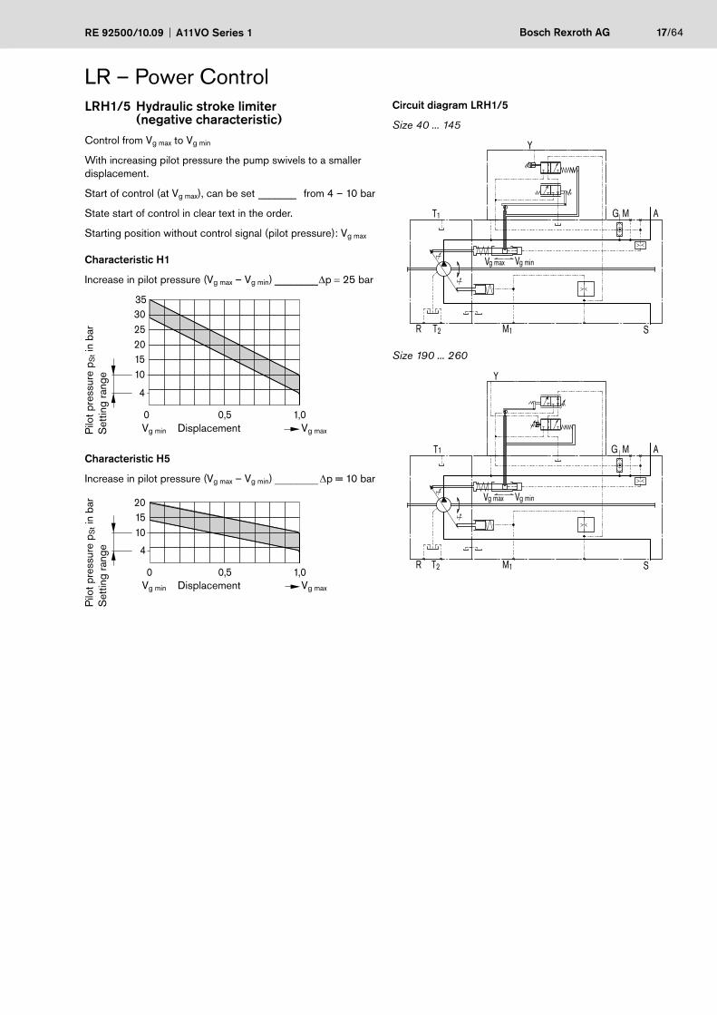
LRH1/5 Hydraulic stroke limiter(negative characteristic)
Control from Vg max to Vg min
With increasing pilot pressure the pump swivels to a smaller displacement.
Start of control (at Vg max), can be set _______ from 4 – 10 bar
State start of control in clear text in the order.
Starting position without control signal (pilot pressure): Vg max
Characteristic H1
Increase in pilot pressure (Vg max – Vg min) ________Δp = 25 bar
4
0 1,00,5
3530
10152025
Pilo
t pre
ssur
e p S
t in
bar
Set
ting
rang
e
DisplacementVg min Vg max
Characteristic H5
Increase in pilot pressure (Vg max – Vg min) ________ Δp = 10 bar
4
0 1,00,5
101520
Pilo
t pre
ssur
e p S
t in
bar
Set
ting
rang
e
DisplacementVg min Vg max
Circuit diagram LRH1/5
Size 40 ... 145
T1
T2R
g ming maxV V
M1 S
AMG
Y
Size 190 ... 260
T1
T2R
g ming maxV V
M1 S
AMG
Y
LR – Power Control

18/64 Bosch Rexroth AG A11VO Series 1 RE 92500/10.09
LRH2/6 Hydraulic stroke limiter (positive characteristic)Control from Vg min to Vg max
With increasing pilot pressure the pump swivels to a higher displacement.
Start of control (at Vg min), can be set _________ from 4–10 bar
State start of control in clear text in the order.
Starting position without control signal (pilot pressure):
– at operating pressure and external control pressure < 30 bar: Vg max
– at operating pressure or external control pressure > 30 bar: Vg min
Characteristic H2
Increase in pilot pressure (Vg min – Vg max) _______ Δp = 25 bar
4
0 1,00,5
3530
10152025
Pilo
t pre
ssur
e p S
t in
bar
Set
ting
rang
e
DisplacementVg min Vg max
Characteristic H6
Increase in pilot pressure (Vg min – Vg max) _______ Δp = 10 bar
Pilo
t pre
ssur
e p S
t in
bar
Set
ting
rang
e
DisplacementVg min Vg max
4
0 1,00,5
101520
LR – Power ControlCircuit diagram LRH2/6
Size 40 ... 145
T1
T2R
g ming maxV V
M1 S
AMG
Y
Size 190 ... 260
T1
T2R
g ming maxV V
M1 S
AMG
Y
RE 92500/10.09 A11VO Series 1 Bosch Rexroth AG 19/64
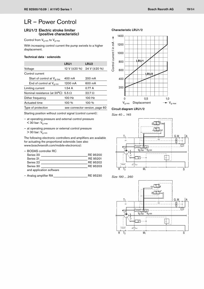
LRU1/2 Electric stroke limiter (positive characteristic)
Control from Vg min to Vg max
With increasing control current the pump swivels to a higher displacement.
Technical data - solenoids
LRU1 LRU2
Voltage 12 V (±20 %) 24 V (±20 %)
Control current
Start of control at Vg max 400 mA 200 mA
End of control at Vg min 1200 mA 600 mA
Limiting current 1.54 A 0.77 A
Nominal resistance (at 20°C) 5.5 Ω 22.7 Ω
Dither frequency 100 Hz 100 Hz
Actuated time 100 % 100 %
Type of protection see connector version, page 60
Starting position without control signal (control current):
at operating pressure and external control pressure –< 30 bar: Vg max
at operating pressure or external control pressure –> 30 bar: Vg min
The following electronic controllers and amplifiers are available for actuating the proportional solenoids (see also www.boschrexroth.com/mobile-electronics):
BODAS controller RC –Series 20 ______________________________ RE 95200Series 21 _______________________________ RE 95201Series 22 ______________________________ RE 95202Series 30 ______________________________ RE 95203and application software
Analog amplifier RA – ______________________ RE 95230
LR – Power ControlCharacteristic LRU1/2
0 1,00,5
200
400
600
800
1000
1200
1400
Con
trol
cur
rent
I in
mA
DisplacementVg min Vg max
LRU1
LRU2
Circuit diagram LRU1/2
Size 40 ... 145
T1
T2R
g ming maxV V
M1 S
AMG
Size 190 ... 260
T1
T2R
g ming maxV V
M1 S
AMG
20/64 Bosch Rexroth AG A11VO Series 1 RE 92500/10.09
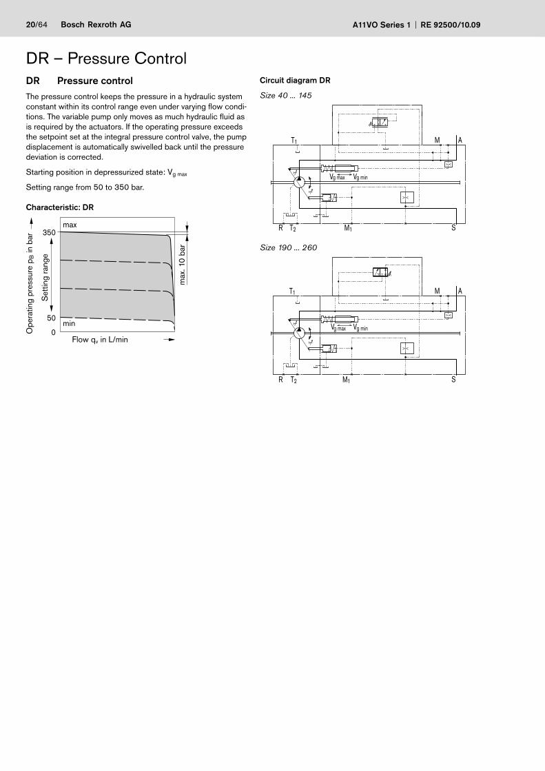
DR – Pressure ControlDR Pressure controlThe pressure control keeps the pressure in a hydraulic system constant within its control range even under varying flow condi-tions. The variable pump only moves as much hydraulic fluid as is required by the actuators. If the operating pressure exceeds the setpoint set at the integral pressure control valve, the pump displacement is automatically swivelled back until the pressure deviation is corrected.
Starting position in depressurized state: Vg max
Setting range from 50 to 350 bar.
Characteristic: DR
350
0
50
max
Ope
ratin
g pr
essu
re p
B in
bar
Flow qv in L/min
max
. 10
bar
Set
ting
rang
e
min
Circuit diagram DR
Size 40 ... 145
T1
T2R
g ming max VV
M1 S
AM
Size 190 ... 260
T1
T2R
g ming max VV
M1 S
AM
RE 92500/10.09 A11VO Series 1 Bosch Rexroth AG 21/64
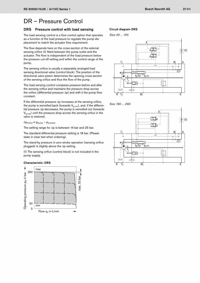
DR – Pressure ControlDRS Pressure control with load sensingThe load sensing control is a flow control option that operates as a function of the load pressure to regulate the pump dis-placement to match the actuator flow requirement.
The flow depends here on the cross section of the external sensing orifice (1) fitted between the pump outlet and the actuator. The flow is independent of the load pressure below the pressure cut-off setting and within the control range of the pump.
The sensing orifice is usually a separately arranged load sensing directional valve (control block). The position of the directional valve piston determines the opening cross section of the sensing orifice and thus the flow of the pump.
The load sensing control compares pressure before and after the sensing orifice and maintains the pressure drop across the orifice (differential pressure Δp) and with it the pump flow constant.
If the differential pressure Δp increases at the sensing orifice, the pump is swivelled back (towards Vg min), and, if the differen-tial pressure Δp decreases, the pump is swivelled out (towards Vg max) until the pressure drop across the sensing orifice in the valve is restored.
Δporifice = ppump – pactuator
The setting range for Δp is between 14 bar and 25 bar.
The standard differential pressure setting is 18 bar. (Please state in clear text when ordering).
The stand-by pressure in zero stroke operation (sensing orifice plugged) is slightly above the Δp setting.
(1) The sensing orifice (control block) is not included in the pump supply.
Characteristic: DRS
350
0
50
max
Ope
ratin
g pr
essu
re p
B in
bar
Flow qv in L/min
max
. 10
bar
min
Circuit diagram DRS
Size 40 ... 145
T1
T2R
g ming max VV
M1 S
AM
X
Size 190 ... 260
T1
T2R
g ming max VV
M1 S
AM
X
(1)
(1)
22/64 Bosch Rexroth AG A11VO Series 1 RE 92500/10.09
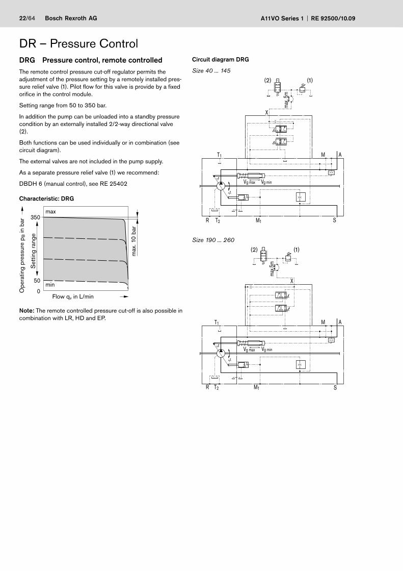
DR – Pressure ControlDRG Pressure control, remote controlledThe remote control pressure cut-off regulator permits the adjustment of the pressure setting by a remotely installed pres-sure relief valve (1). Pilot flow for this valve is provide by a fixed orifice in the control module.
Setting range from 50 to 350 bar.
In addition the pump can be unloaded into a standby pressure condition by an externally installed 2/2-way directional valve (2).
Both functions can be used individually or in combination (see circuit diagram).
The external valves are not included in the pump supply.
As a separate pressure relief valve (1) we recommend:
DBDH 6 (manual control), see RE 25402
Characteristic: DRG
350
0
50
max
Ope
ratin
g pr
essu
re p
B in
bar
Flow qv in L/min
max
. 10
bar
Set
ting
rang
e
min
Note: The remote controlled pressure cut-off is also possible in combination with LR, HD and EP.
Circuit diagram DRG
Size 40 ... 145
T1
T2R
g ming max VV
M1 S
AM
max.
5m
X
(2) (1)
Size 190 ... 260
T1
T2R
g ming max VV
M1 S
AM
max.5
m
X
(2) (1)
RE 92500/10.09 A11VO Series 1 Bosch Rexroth AG 23/64
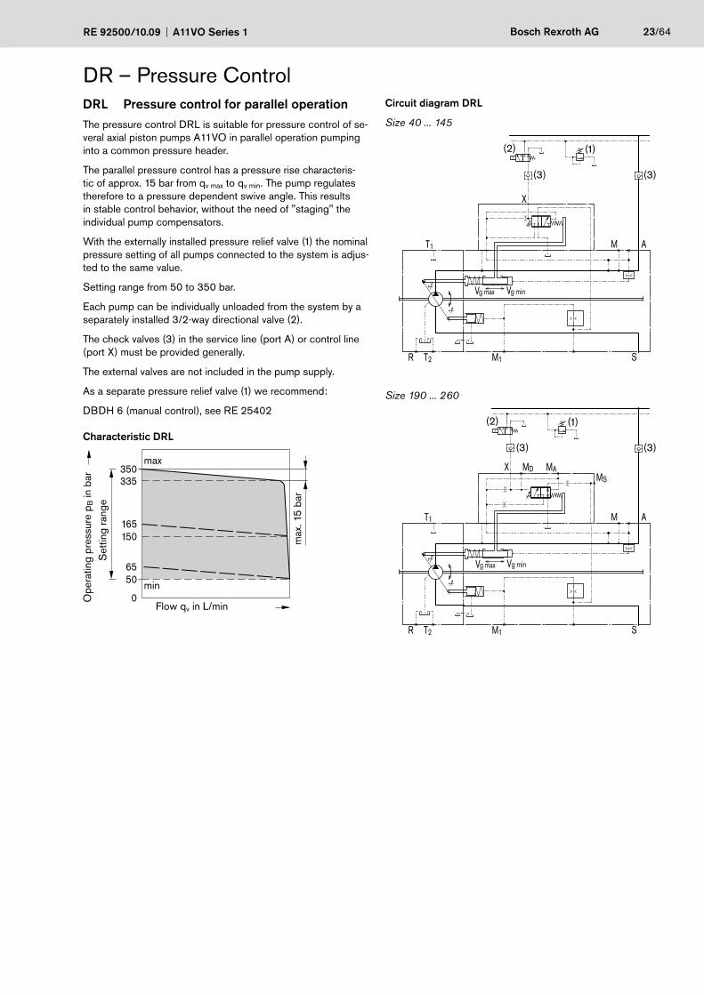
DR – Pressure ControlDRL Pressure control for parallel operationThe pressure control DRL is suitable for pressure control of se-veral axial piston pumps A11VO in parallel operation pumping into a common pressure header.
The parallel pressure control has a pressure rise characteris-tic of approx. 15 bar from qv max to qv min. The pump regulates therefore to a pressure dependent swive angle. This results in stable control behavior, without the need of "staging" the individual pump compensators.
With the externally installed pressure relief valve (1) the nominal pressure setting of all pumps connected to the system is adjus-ted to the same value.
Setting range from 50 to 350 bar.
Each pump can be individually unloaded from the system by a separately installed 3/2-way directional valve (2).
The check valves (3) in the service line (port A) or control line (port X) must be provided generally.
The external valves are not included in the pump supply.
As a separate pressure relief valve (1) we recommend:
DBDH 6 (manual control), see RE 25402
Characteristic DRL
350
0
6550
335
150165
max
Ope
ratin
g pr
essu
re p
B in
bar
Flow qv in L/min
max
. 15
bar
Set
ting
rang
e
min
Circuit diagram DRL
Size 40 ... 145
T1
T2R
X
g ming maxV V
M1 S
AM
(2)
(3)
(1)
(3)
Size 190 ... 260
T1
T2R
X MD MAMS
g ming maxV V
M1 S
AM
(2)
(3)
(1)
(3)
24/64 Bosch Rexroth AG A11VO Series 1 RE 92500/10.09
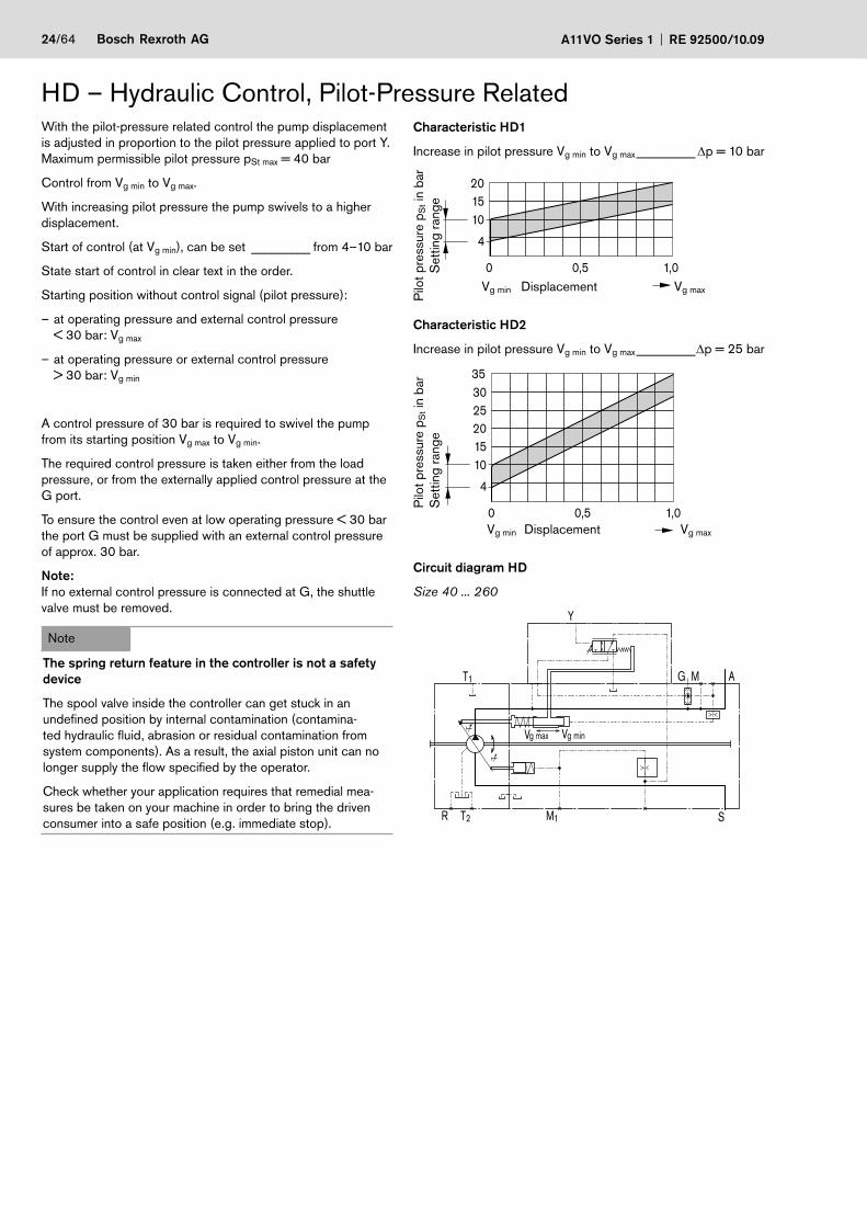
Characteristic HD1
Increase in pilot pressure Vg min to Vg max _________ Δp = 10 bar
Pilo
t pre
ssur
e p S
t in
bar
Set
ting
rang
e
Displacement Vg maxVg min
4
0 1,00,5
101520
Characteristic HD2
Increase in pilot pressure Vg min to Vg max _________Δp = 25 bar
Pilo
t pre
ssur
e p S
t in
bar
Set
ting
rang
e
Displacement Vg maxVg min
4
0 1,00,5
3530
10152025
Circuit diagram HD
Size 40 ... 260
T1
T2R
g ming maxV V
M1 S
AMG
Y
HD – Hydraulic Control, Pilot-Pressure RelatedWith the pilot-pressure related control the pump displacement is adjusted in proportion to the pilot pressure applied to port Y.Maximum permissible pilot pressure pSt max = 40 bar
Control from Vg min to Vg max.
With increasing pilot pressure the pump swivels to a higher displacement.
Start of control (at Vg min), can be set _________ from 4–10 bar
State start of control in clear text in the order.
Starting position without control signal (pilot pressure):
at operating pressure and external control pressure –< 30 bar: Vg max
at operating pressure or external control pressure –> 30 bar: Vg min
A control pressure of 30 bar is required to swivel the pump from its starting position Vg max to Vg min.
The required control pressure is taken either from the load pressure, or from the externally applied control pressure at the G port.
To ensure the control even at low operating pressure < 30 bar the port G must be supplied with an external control pressure of approx. 30 bar.
Note:If no external control pressure is connected at G, the shuttle valve must be removed.
Note
The spring return feature in the controller is not a safety device
The spool valve inside the controller can get stuck in an undefined position by internal contamination (contamina-ted hydraulic fluid, abrasion or residual contamination from system components). As a result, the axial piston unit can no longer supply the flow specified by the operator.
Check whether your application requires that remedial mea-sures be taken on your machine in order to bring the driven consumer into a safe position (e.g. immediate stop).
RE 92500/10.09 A11VO Series 1 Bosch Rexroth AG 25/64
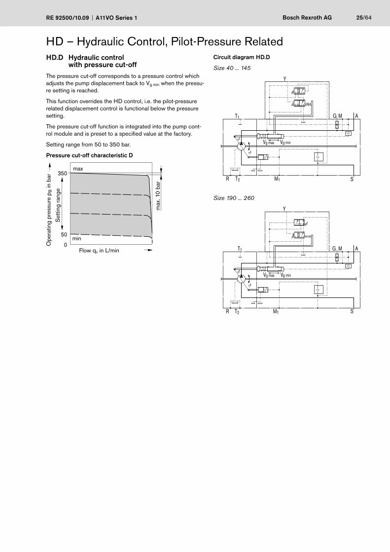
HD – Hydraulic Control, Pilot-Pressure RelatedHD.D Hydraulic control
with pressure cut-offThe pressure cut-off corresponds to a pressure control which adjusts the pump displacement back to Vg min when the pressu-re setting is reached.
This function overrides the HD control, i.e. the pilot-pressure related displacement control is functional below the pressure setting.
The pressure cut-off function is integrated into the pump cont-rol module and is preset to a specified value at the factory.
Setting range from 50 to 350 bar.
Pressure cut-off characteristic D
350
0
50
max
Ope
ratin
g pr
essu
re p
B in
bar
Flow qv in L/min
max
. 10
bar
Set
ting
rang
e
min
Circuit diagram HD.D
Size 40 ... 145
g ming maxV V
M1 S
AMGT1
T2R
Y
Size 190 ... 260
Y
T1
T2R
g ming maxV V
M1 S
AMG
26/64 Bosch Rexroth AG A11VO Series 1 RE 92500/10.09
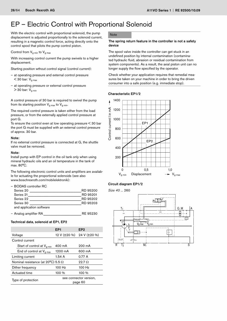
With the electric control with proportional solenoid, the pump displacement is adjusted proportionally to the solenoid current, resulting in a magnetic control force, acting directly onto the control spool that pilots the pump control piston.
Control from Vg min to Vg max
With increasing control current the pump swivels to a higher displacement.
Starting position wthout control signal (control current):
at operating pressure and external control pressure –< 30 bar: Vg max
at operating pressure or external control pressure –> 30 bar: Vg min
A control pressure of 30 bar is required to swivel the pump from its starting position Vg max to Vg min.
The required control pressure is taken either from the load pressure, or from the externally applied control pressure at port G.To ensure the control even at low operating pressure < 30 bar the port G must be supplied with an external control pressure of approx. 30 bar.
Note:If no external control pressure is connected at G, the shuttle valve must be removed.
Note:Install pump with EP control in the oil tank only when using mineral hydraulic oils and an oil temperature in the tank of max. 80°C.
The following electronic control units and amplifiers are availab-le for actuating the proportional solenoids (see alsowww.boschrexroth.com/mobilelektronik):
BODAS controller RC –Series 20 ______________________________RD 95200Series 21 _______________________________ RD 95201Series 22 ______________________________RD 95202Series 30 ______________________________RD 95203and application software
Analog amplifier RA – ______________________ RE 95230
Technical data, solenoid at EP1, EP2
EP1 EP2
Voltage 12 V (±20 %) 24 V (±20 %)
Control current
Start of control at Vg min 400 mA 200 mA
End of control at Vg max 1200 mA 600 mA
Limiting current 1.54 A 0.77 A
Nominal resistance (at 20°C) 5.5 Ω 22.7 Ω
Dither frequency 100 Hz 100 Hz
Actuated time 100 % 100 %
Type of protectionsee connector version,
page 60
EP – Electric Control with Proportional SolenoidNote
The spring return feature in the controller is not a safety device
The spool valve inside the controller can get stuck in an undefined position by internal contamination (contamina-ted hydraulic fluid, abrasion or residual contamination from system components). As a result, the axial piston unit can no longer supply the flow specified by the operator.
Check whether your application requires that remedial mea-sures be taken on your machine in order to bring the driven consumer into a safe position (e.g. immediate stop).
Characteristic EP1/2
0 1,00,5
200
400
600
800
1000
1200
1400
DisplacementVg min Vg max
Con
trol
cur
rent
I in
mA
EP1
EP2
Circuit diagram EP1/2
Size 40 ... 260
T1
T2R
g ming maxV V
M1 S
AMG
RE 92500/10.09 A11VO Series 1 Bosch Rexroth AG 27/64
Circuit diagram EP.D
Size 40 ... 145
g ming maxV V
M1 S
AMGT1
T2R
Size 190 ... 260
g ming maxV V
M1 S
AMGT1
T2R
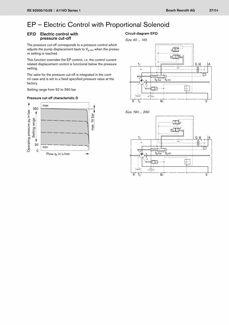
EP – Electric Control with Proportional SolenoidEP.D Electric control with pressure cut-offThe pressure cut-off corresponds to a pressure control which adjusts the pump displacement back to Vg min when the pressu-re setting is reached.
This function overrides the EP control, i.e. the control current related displacement control is functional below the pressure setting.
The valve for the pressure cut-off is integrated in the cont-rol case and is set to a fixed specified pressure value at the factory.
Setting range from 50 to 350 bar
Pressure cut-off characteristic D
350
0
50
max
Ope
ratin
g pr
essu
re p
B in
bar
Flow qv in L/min
max
. 10
bar
Set
ting
rang
e
min
28/64 Bosch Rexroth AG A11VO Series 1 RE 92500/10.09
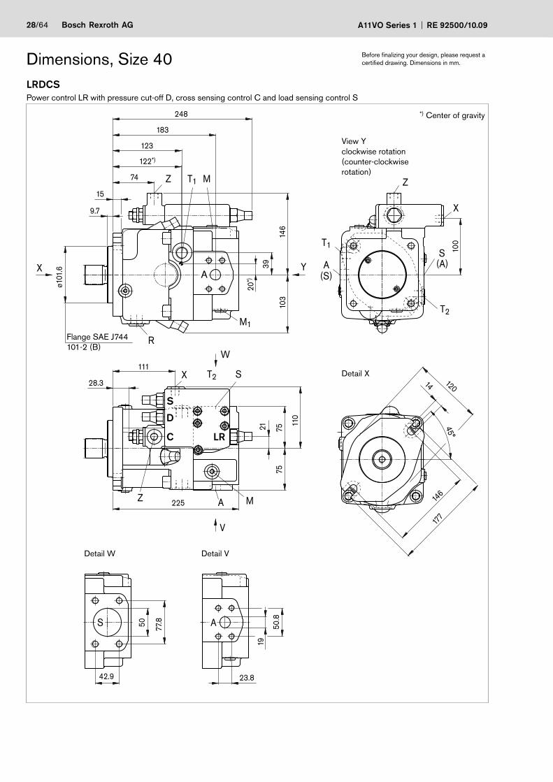
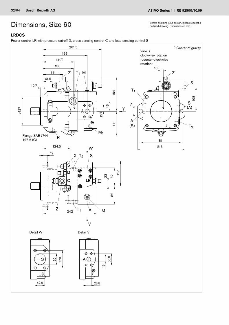
LRDCSPower control LR with pressure cut-off D, cross sensing control C and load sensing control S
Dimensions, Size 40 Before finalizing your design, please request a certified drawing. Dimensions in mm.
Z T1 M
R
M1
Z
X
S(A)
T2
A(S)
T1
S
Z A M
X T2 S
A
A21
74
122*)
20*)
111
23.8
50.8
19
28.3
146
248
183
123
15
12014
146
9.7
103
ø101
.6 39
110
7575
225
42.9
77.850
177
45°
X Y
W
V
100
View Y clockwise rotation (counter-clockwise rotation)
Detail X
Detail W Detail V
Flange SAE J744101-2 (B)
*) Center of gravity
S
D
C LR
RE 92500/10.09 A11VO Series 1 Bosch Rexroth AG 29/64
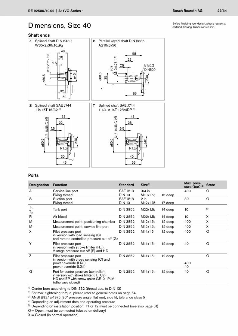
Dimensions, Size 40Shaft endsZ Splined shaft DIN 5480
W35x2x30x16x9gP Parallel keyed shaft DIN 6885,
AS10x8x56M
12x1
.75
1) 2
)ø8
0.5
50
ø40
9.5
28
40
32
ø80.
5
E1x0.2DIN509
M12
x1.7
5 1)
2)
66
ø40
7.5
22
35
ø32
58
S Splined shaft SAE J744 1 in 15T 16/32 3)
T Splined shaft SAE J7441 1/4 in 14T 12/24DP 3)
46
ø80.
5
22
30
3/8-
16U
NC
-2B
ø40
38
7.5
R1.6
56
ø80.
5
28
40
7/16
-14U
NC
-2B
ø40
48
9.5
R1.6
Ports
Designation Function Standard Size2) Max. pres-sure (bar) 4) State
A Service line port SAE J518 3/4 in 400 OFixing thread DIN 13 M10x1.5; 16 deep
S Suction port SAE J518 2 in 30 OFixing thread DIN 13 M12x1.75; 17 deep
T1,T2
Tank port DIN 3852 M22x1.5; 14 deep 10 5)
R Air bleed DIN 3852 M22x1.5; 14 deep 10 XM1 Measurement point, positioning chamber DIN 3852 M12x1.5; 12 deep 400 XM Measurement point, service line port DIN 3852 M12x1.5; 12 deep 400 XX Pilot pressure port
in version with load sensing (S)and remote controlled pressure cut-off (G)
DIN 3852 M14x1.5 12 deep 400 O
Y Pilot pressure portin version with stroke limiter (H...),2-stage pressure cut-off (E) and HD
DIN 3852 M14x1.5; 12 deep 40 O
Z Pilot pressure portin version with cross sensing (C) andpower override (LR3)power override (LG1)
DIN 3852 M14x1.5; 12 deep
40040
O
G Port for control pressure (controller)in version with stroke limiter (H.., U2),HD and EP with screw union GE10 - PLM(otherwise closed)
DIN 3852 M14x1.5; 12 deep 40 O
1) Center bore according to DIN 332 (thread acc. to DIN 13)2) For max. tightening torque, please refer to general notes on page 643) ANSI B92.1a-1976, 30° pressure angle, flat root, side fit, tolerance class 5 4) Depending on adjustment data and operating pressure5) Depending on installation position, T1 or T2 must be connected (see also page 61)O = Open, must be connected (closed on delivery)X = Closed (in normal operation)
Before finalizing your design, please request a certified drawing. Dimensions in mm.
30/64 Bosch Rexroth AG A11VO Series 1 RE 92500/10.09
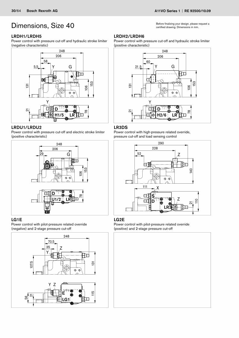
Dimensions, Size 40LRDH1/LRDH5Power control with pressure cut-off and hydraulic stroke limiter (negative characteristic)
LRDH2/LRDH6Power control with pressure cut-off and hydraulic stroke limiter (positive characteristic)
Y
Y
78
248206
58
5.5
153
21
10613
1
G
20660
10613
1
7815
3
248
21.5
Y
Y G
21LRDU1/LRDU2Power control with pressure cut-off and electric stroke limiter (positive characteristic)
LR3DSPower control with high-pressure related override,pressure cut-off and load sensing control
G206
106 15
3
29
248
78 Z
Z
X
228
11121
290
52
140
110
LG1EPower control with pilot-pressure related override(negative) and 2-stage pressure cut-off
LG2EPower control with pilot-pressure related override(positive) and 2-stage pressure cut-off
Y
Y
Z
Z
70.5
107.
556
21
131
115
248
35
Before finalizing your design, please request a certified drawing. Dimensions in mm.
DH1/5 LR
DH2/6 LR
DU1/2 LR
S
LR3D
ELG1
RE 92500/10.09 A11VO Series 1 Bosch Rexroth AG 31/64
Dimensions, Size 40 Before finalizing your design, please request a certified drawing. Dimensions in mm.
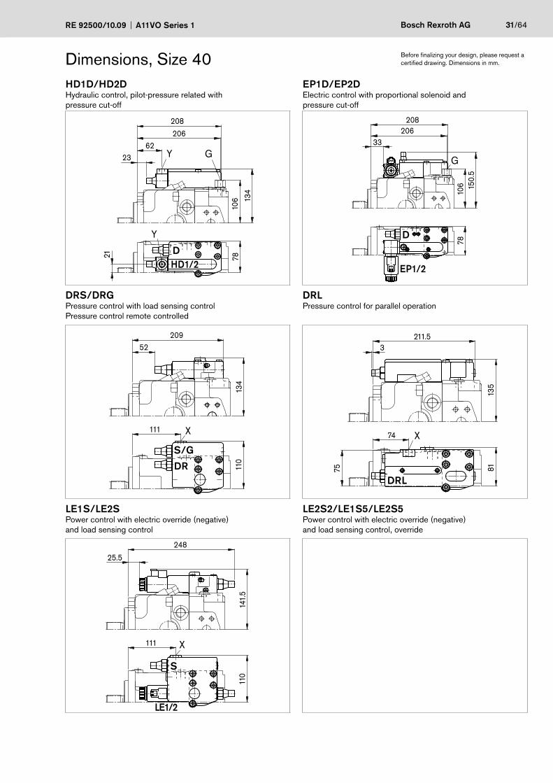
HD1D/HD2DHydraulic control, pilot-pressure related with pressure cut-off
EP1D/EP2DElectric control with proportional solenoid and pressure cut-off
106
20662
21 7813
4
208
23 Y
Y
GG
206
106 15
0.5
78
208
33
DRS/DRGPressure control with load sensing control Pressure control remote controlled
DRLPressure control for parallel operation
X111
110
134
20952
X74
75 8113
5
211.53
LE1S/LE2SPower control with electric override (negative)and load sensing control
LE2S2/LE1S5/LE2S5Power control with electric override (negative)and load sensing control, override
X111
110
141.
5
248
25.5
LE1/2
DHD1/2
D
EP1/2
S/G
DRDRL
S
32/64 Bosch Rexroth AG A11VO Series 1 RE 92500/10.09
LRDCSPower control LR with pressure cut-off D, cross sensing control C and load sensing control S
Dimensions, Size 60 Before finalizing your design, please request a certified drawing. Dimensions in mm.
Z T1 A M
Z
X
S(A)
T2
A(S)
T1
S A
A
Z T1
RM1
M
X T2 S
23
124.5
15*)
140*)
88
41.5
111
154
112
8282
17
10*)
50.8
19
242
261.5
ø127
198
136
12.7
46
213
181
42.9 23.8
77.850
19
Y
W
V
108
View Y clockwise rotation (counter-clockwise rotation)
Detail W Detail V
*) Center of gravity
S
D
C LR
Flange SAE J744127-2 (C)
RE 92500/10.09 A11VO Series 1 Bosch Rexroth AG 33/64
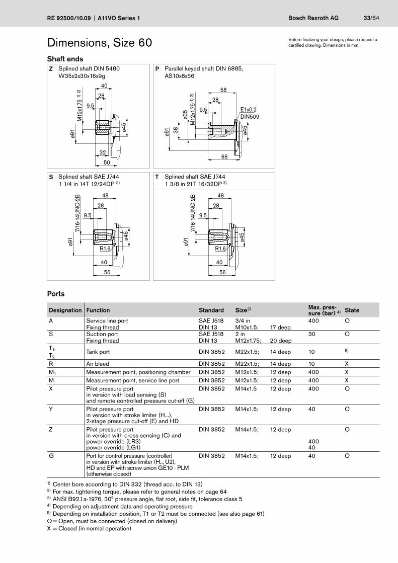
Dimensions, Size 60Shaft endsZ Splined shaft DIN 5480
W35x2x30x16x9gP Parallel keyed shaft DIN 6885,
AS10x8x56M
12x1
.75
1) 2
)ø9
1
50
ø45
9.5
28
40
32
ø91
E1x0.2DIN509
M12
x1.7
5 1)
2)
66
ø45
9.5
28
38
ø35
58
S Splined shaft SAE J7441 1/4 in 14T 12/24DP 3)
T Splined shaft SAE J744 1 3/8 in 21T 16/32DP 3)
56
ø91
28
40
7/16
-14U
NC
-2B
ø45
48
9.5
R1.6
56
ø91
28
40
7/16
-14U
NC
-2B
ø45
48
9.5
R1.6
Ports
Designation Function Standard Size2) Max. pres-sure (bar) 4) State
A Service line port SAE J518 3/4 in 400 OFixing thread DIN 13 M10x1.5; 17 deep
S Suction port SAE J518 2 in 30 OFixing thread DIN 13 M12x1.75; 20 deep
T1,T2
Tank port DIN 3852 M22x1.5; 14 deep 10 5)
R Air bleed DIN 3852 M22x1.5; 14 deep 10 XM1 Measurement point, positioning chamber DIN 3852 M12x1.5; 12 deep 400 XM Measurement point, service line port DIN 3852 M12x1.5; 12 deep 400 XX Pilot pressure port
in version with load sensing (S)and remote controlled pressure cut-off (G)
DIN 3852 M14x1.5 12 deep 400 O
Y Pilot pressure portin version with stroke limiter (H...),2-stage pressure cut-off (E) and HD
DIN 3852 M14x1.5; 12 deep 40 O
Z Pilot pressure portin version with cross sensing (C) andpower override (LR3)power override (LG1)
DIN 3852 M14x1.5; 12 deep
40040
O
G Port for control pressure (controller)in version with stroke limiter (H.., U2),HD and EP with screw union GE10 - PLM(otherwise closed)
DIN 3852 M14x1.5; 12 deep 40 O
1) Center bore according to DIN 332 (thread acc. to DIN 13)2) For max. tightening torque, please refer to general notes on page 643) ANSI B92.1a-1976, 30° pressure angle, flat root, side fit, tolerance class 54) Depending on adjustment data and operating pressure5) Depending on installation position, T1 or T2 must be connected (see also page 61)O = Open, must be connected (closed on delivery)X = Closed (in normal operation)
Before finalizing your design, please request a certified drawing. Dimensions in mm.
34/64 Bosch Rexroth AG A11VO Series 1 RE 92500/10.09
Dimensions, Size 60 Before finalizing your design, please request a certified drawing. Dimensions in mm.
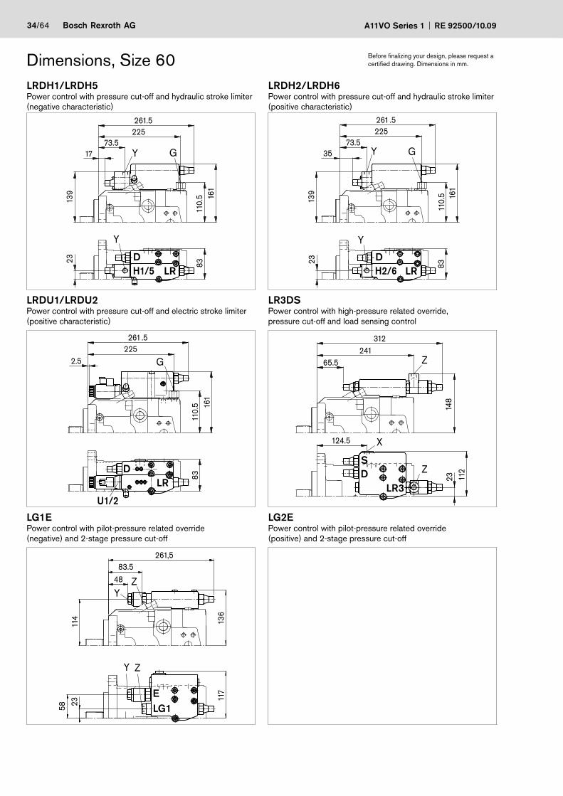
LRDH1/LRDH5Power control with pressure cut-off and hydraulic stroke limiter (negative characteristic)
LRDH2/LRDH6Power control with pressure cut-off and hydraulic stroke limiter (positive characteristic)
83
22573.5
139
110.
5 161
261.5
17
Y
GY
23
225
139
83
73.5
110.
5 161
261.5
Y
GY35
23LRDU1/LRDU2Power control with pressure cut-off and electric stroke limiter (positive characteristic)
LR3DSPower control with high-pressure related override,pressure cut-off and load sensing control
G225
2.5
261.5
110.
583
161
U1/2
241
124.523 11
2
148
312
65.5
X
Z
Z
LG1EPower control with pilot-pressure related override(negative) and 2-stage pressure cut-off
LG2EPower control with pilot-pressure related override(positive) and 2-stage pressure cut-off
58 23
83.5
114
117
136
261,5
48
Y
Y
Z
Z
DH1/5 LR
DH2/6 LR
DLR
S
LR3D
ELG1
RE 92500/10.09 A11VO Series 1 Bosch Rexroth AG 35/64
Dimensions, Size 60 Before finalizing your design, please request a certified drawing. Dimensions in mm.
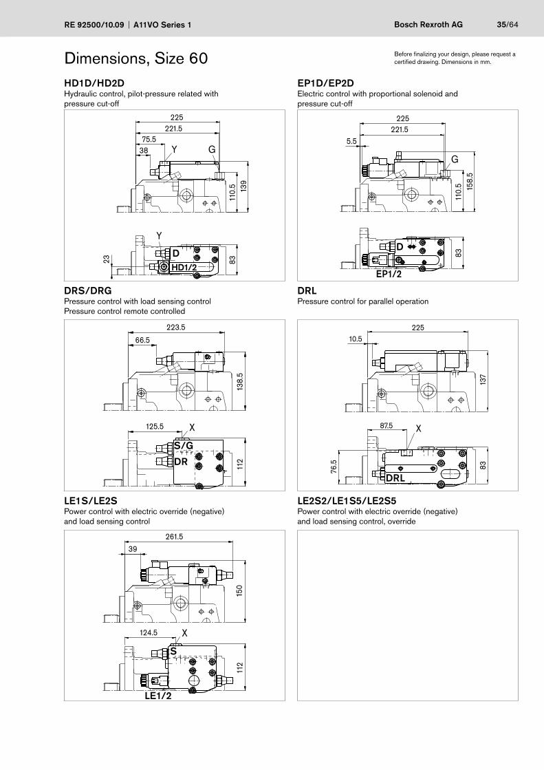
HD1D/HD2DHydraulic control, pilot-pressure related with pressure cut-off
EP1D/EP2DElectric control with proportional solenoid andpressure cut-off
8311
0.5
23225
75.5
139
221.5
38 Y G
Y
G
110.
5
225
8315
8.5
221.55.5
EP1/2
DRS/DRGPressure control with load sensing controlPressure control remote controlled
DRLPressure control for parallel operation
66.5
138.
5
223.5
112
125.5 X X
76.5
87.5
8313
7
22510.5
LE1S/LE2SPower control with electric override (negative)and load sensing control
LE2S2/LE1S5/LE2S5Power control with electric override (negative)and load sensing control, override
X124.5
150
261.5
112
39
LE1/2
DHD1/2
D
S/G
DR
DRL
S
36/64 Bosch Rexroth AG A11VO Series 1 RE 92500/10.09
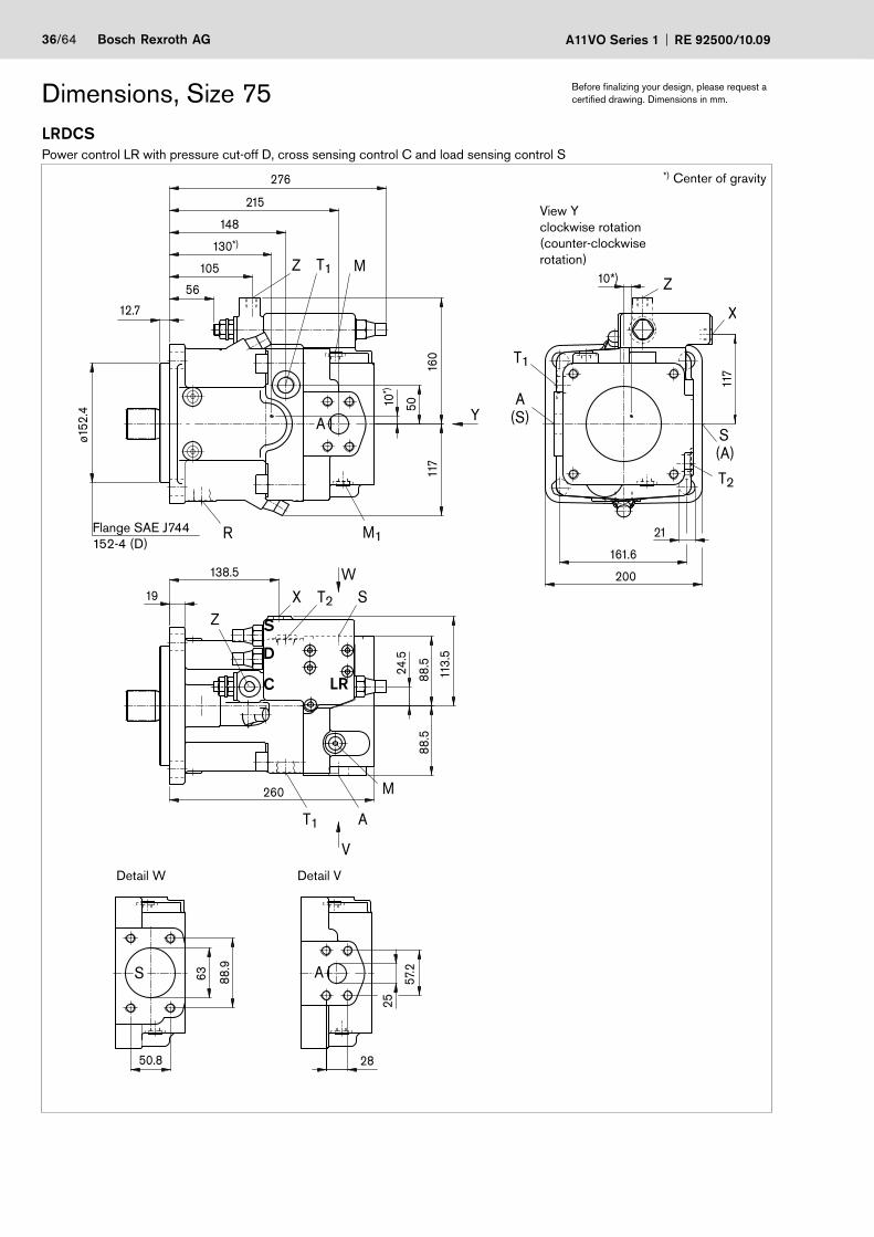
LRDCSPower control LR with pressure cut-off D, cross sensing control C and load sensing control S
Dimensions, Size 75 Before finalizing your design, please request a certified drawing. Dimensions in mm.
Z
X
S(A)
T2
(S)A
T1
Z
T1 A
A
A
M
X T2 S
S
R M1
Z T1 M10*)
63
24.5
138.5
130*)
105
56
10*)
28
57.2
25
160
21
200
161.6
88.9
50.8
113.
5
88.5
88.5
19
260
117
ø152
.4
276
215
148
12.7
50 Y
W
V
117
Detail W Detail V
View Y clockwise rotation (counter-clockwise rotation)
*) Center of gravity
S
D
C LR
Flange SAE J744152-4 (D)
RE 92500/10.09 A11VO Series 1 Bosch Rexroth AG 37/64
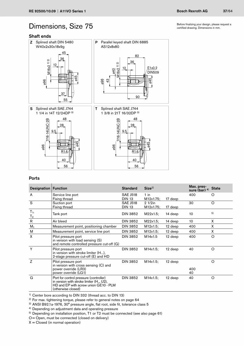
Dimensions, Size 75Shaft endsZ Splined shaft DIN 5480
W40x2x30x18x9gP Parallel keyed shaft DIN 6885
AS12x8x80M
16x2
1) 2
)ø9
6
55
ø45
12
36
45
37
ø96
E1x0.2DIN509
M16
x2 1)
2)
90
ø45
12
36
43
ø40
82
S Splined shaft SAE J7441 1/4 in 14T 12/24DP 3)
T Splined shaft SAE J744 1 3/8 in 21T 16/32DP 3)
56
ø96
28
40
7/16
-14U
NC
-2B
ø45
48
9.5
R1.6
56
ø96
28
40
7/16
-14U
NC
-2B
ø45
48
9.5
R1.6
Ports
Designation Function Standard Size2) Max. pres-sure (bar) 4) State
A Service line port SAE J518 1 in 400 OFixing thread DIN 13 M12x1.75; 17 deep
S Suction port SAE J518 2 1/2in 30 OFixing thread DIN 13 M12x1.75; 17 deep
T1,T2
Tank port DIN 3852 M22x1.5; 14 deep 10 5)
R Air bleed DIN 3852 M22x1.5; 14 deep 10 XM1 Measurement point, positioning chamber DIN 3852 M12x1.5; 12 deep 400 XM Measurement point, service line port DIN 3852 M12x1.5; 12 deep 400 XX Pilot pressure port
in version with load sensing (S)and remote controlled pressure cut-off (G)
DIN 3852 M14x1.5 12 deep 400 O
Y Pilot pressure portin version with stroke limiter (H...),2-stage pressure cut-off (E) and HD
DIN 3852 M14x1.5; 12 deep 40 O
Z Pilot pressure portin version with cross sensing (C) andpower override (LR3)power override (LG1)
DIN 3852 M14x1.5; 12 deep
40040
O
G Port for control pressure (controller)in version with stroke limiter (H.., U2),HD and EP with screw union GE10 - PLM(otherwise closed)
DIN 3852 M14x1.5; 12 deep 40 O
1) Center bore according to DIN 332 (thread acc. to DIN 13)2) For max. tightening torque, please refer to general notes on page 643) ANSI B92.1a-1976, 30° pressure angle, flat root, side fit, tolerance class 5 4) Depending on adjustment data and operating pressure5) Depending on installation position, T1 or T2 must be connected (see also page 61)O = Open, must be connected (closed on delivery)X = Closed (in normal operation)
Before finalizing your design, please request a certified drawing. Dimensions in mm.

38/64 Bosch Rexroth AG A11VO Series 1 RE 92500/10.09
Dimensions, Size 75 Before finalizing your design, please request a certified drawing. Dimensions in mm.
LRDH1/LRDH5Power control with pressure cut-off and hydraulic stroke limiter (negative characteristic)
LRDH2/LRDH6Power control with pressure cut-off and hydraulic stroke limiter (positive characteristic)
Y
Y
G
24.5
145.
5
23987.5
109
89.5
167.
5
276
31 Y
Y
G
109
24.5
23987.5
145.
5
89.5
167.
5
276
49
LRDU1/LRDU2Power control with pressure cut-off and electric stroke limiter (positive characteristic)
LR3DSPower control with high-pressure related override,pressure cut-off and load sensing control
G239
109
89.5
167.
5
276
15 Z
Z
X138.5
255.5
24.5
113.
515
4.5
326.5
80
LG1EPower control with pilot-pressure related override(negative) and 2-stage pressure cut-off
LG2EPower control with pilot-pressure related override(positive) and 2-stage pressure cut-off
Y
Y Z
Z
120.
559
.524
.5
97.5276
62
142.
511
8.5
DH1/5 LR
DH2/6 LR
DLR
S
LR3D
ELG1
U1/2
RE 92500/10.09 A11VO Series 1 Bosch Rexroth AG 39/64
Dimensions, Size 75 Before finalizing your design, please request a certified drawing. Dimensions in mm.
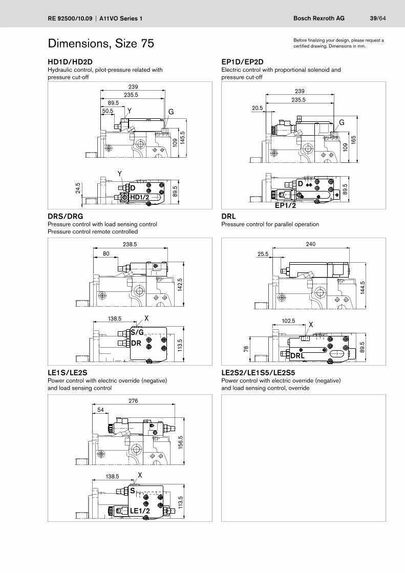
HD1D/HD2DHydraulic control, pilot-pressure related with pressure cut-off
EP1D/EP2DElectric control with proportional solenoid and pressure cut-off
Y G
Y10
9
24.5
239
89.5
89.5
145.
5
235.5
50.5
G
239
109
89.5
165
235.520.5
DRS/DRGPressure control with load sensing control Pressure control remote controlled
DRLPressure control for parallel operation
X138.5
113.
514
2.5
238.5
80
X
78
102.5
89.5
240
144.
5
25.5
LE1S/LE2SPower control with electric override (negative)and load sensing control
LE2S2/LE1S5/LE2S5Power control with electric override (negative)and load sensing control, override
X138.5
113.
515
6.5
27654
DHD1/2
D
S/GDR
DRL
S
EP1/2
LE1/2
40/64 Bosch Rexroth AG A11VO Series 1 RE 92500/10.09
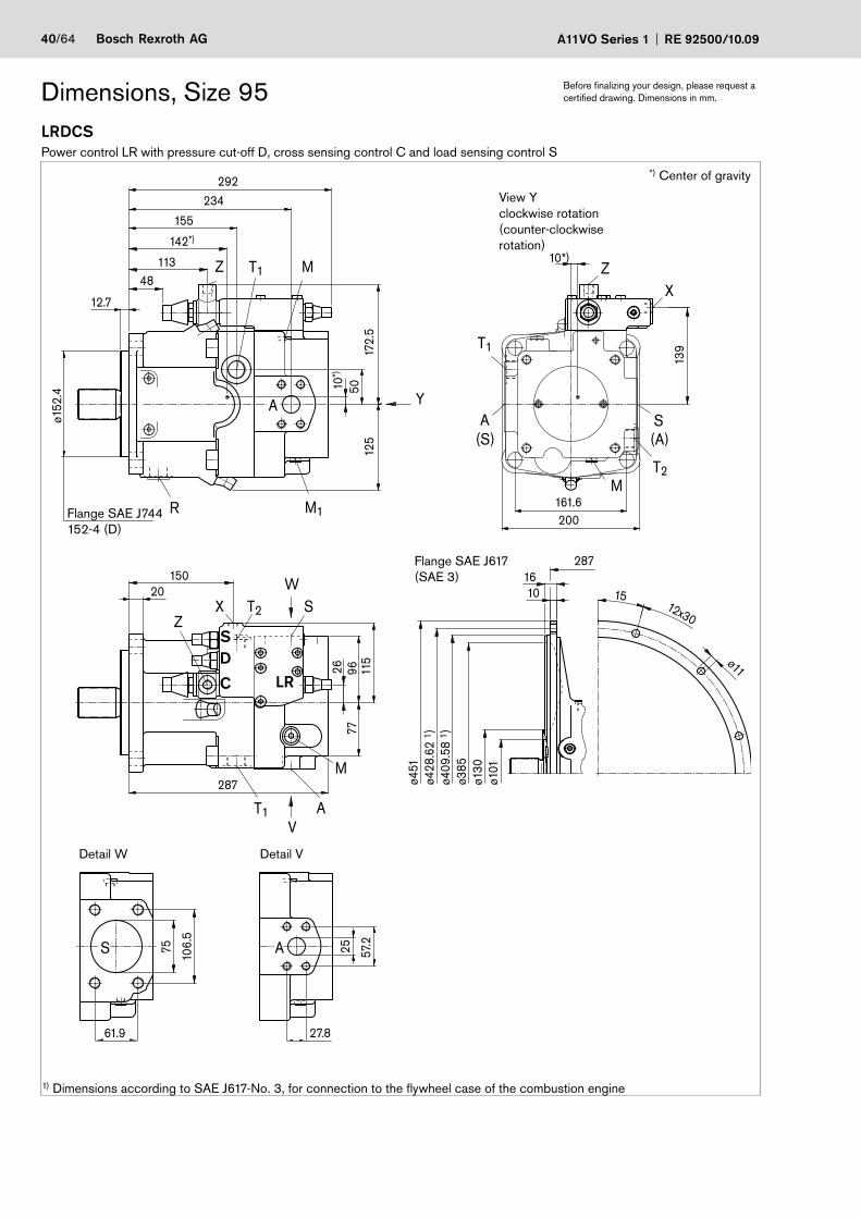
LRDCSPower control LR with pressure cut-off D, cross sensing control C and load sensing control S
Dimensions, Size 95 Before finalizing your design, please request a certified drawing. Dimensions in mm.
ZZ
X
XZ
T1
M
M
T2
T1
M
R
T2
S(A)
A(S)
M1
A
A
S
T1
ø130
ø101
2871610
ø409
.58
1 )ø3
85
ø428
.62
1 )ø4
51
ø11
12x30
15
139
10*)
26
150
10*)
142*)
48113
61.9
106.
5
75 57.225
27.8
161.6200
172.
512
5
ø152
.4
12.7
155
234292
50
20
287
115
9677
Y
W
VA
S
View Y clockwise rotation (counter-clockwise rotation)
Flange SAE J617(SAE 3)
Detail W Detail V
*) Center of gravity
SD
C LR
Flange SAE J744152-4 (D)
1) Dimensions according to SAE J617-No. 3, for connection to the flywheel case of the combustion engine
RE 92500/10.09 A11VO Series 1 Bosch Rexroth AG 41/64
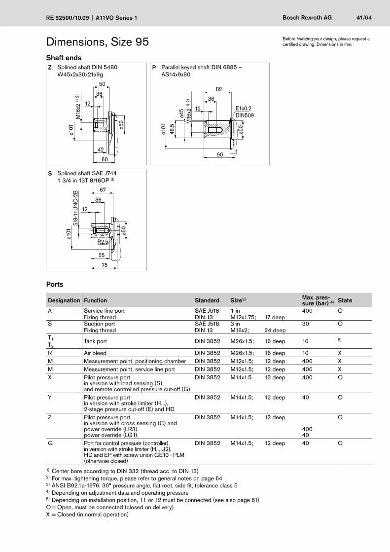
Dimensions, Size 95Shaft endsZ Splined shaft DIN 5480
W45x2x30x21x9gP Parallel keyed shaft DIN 6885 –
AS14x9x80M
16x2
1) 2
)ø1
01
60
ø50
12
36
50
42
ø101
E1x0.2DIN509
M16
x2 1)
2)
90
ø50
12
36
48.5
ø45
82
S Splined shaft SAE J7441 3/4 in 13T 8/16DP 3)
75
ø101
36
55
5/8-
11U
NC
-2B
ø50
67
12
R2.5
Ports
Designation Function Standard Size2) Max. pres-sure (bar) 4) State
A Service line port SAE J518 1 in 400 OFixing thread DIN 13 M12x1.75; 17 deep
S Suction port SAE J518 3 in 30 OFixing thread DIN 13 M16x2; 24 deep
T1,T2
Tank port DIN 3852 M26x1.5; 16 deep 10 5)
R Air bleed DIN 3852 M26x1.5; 16 deep 10 XM1 Measurement point, positioning chamber DIN 3852 M12x1.5; 12 deep 400 XM Measurement point, service line port DIN 3852 M12x1.5; 12 deep 400 XX Pilot pressure port
in version with load sensing (S)and remote controlled pressure cut-off (G)
DIN 3852 M14x1.5 12 deep 400 O
Y Pilot pressure portin version with stroke limiter (H...),2-stage pressure cut-off (E) and HD
DIN 3852 M14x1.5; 12 deep 40 O
Z Pilot pressure portin version with cross sensing (C) andpower override (LR3)power override (LG1)
DIN 3852 M14x1.5; 12 deep
40040
O
G Port for control pressure (controller)in version with stroke limiter (H.., U2),HD and EP with screw union GE10 - PLM(otherwise closed)
DIN 3852 M14x1.5; 12 deep 40 O
1) Center bore according to DIN 332 (thread acc. to DIN 13)2) For max. tightening torque, please refer to general notes on page 643) ANSI B92.1a-1976, 30° pressure angle, flat root, side fit, tolerance class 54) Depending on adjustment data and operating pressure5) Depending on installation position, T1 or T2 must be connected (see also page 61)O = Open, must be connected (closed on delivery)X = Closed (in normal operation)
Before finalizing your design, please request a certified drawing. Dimensions in mm.
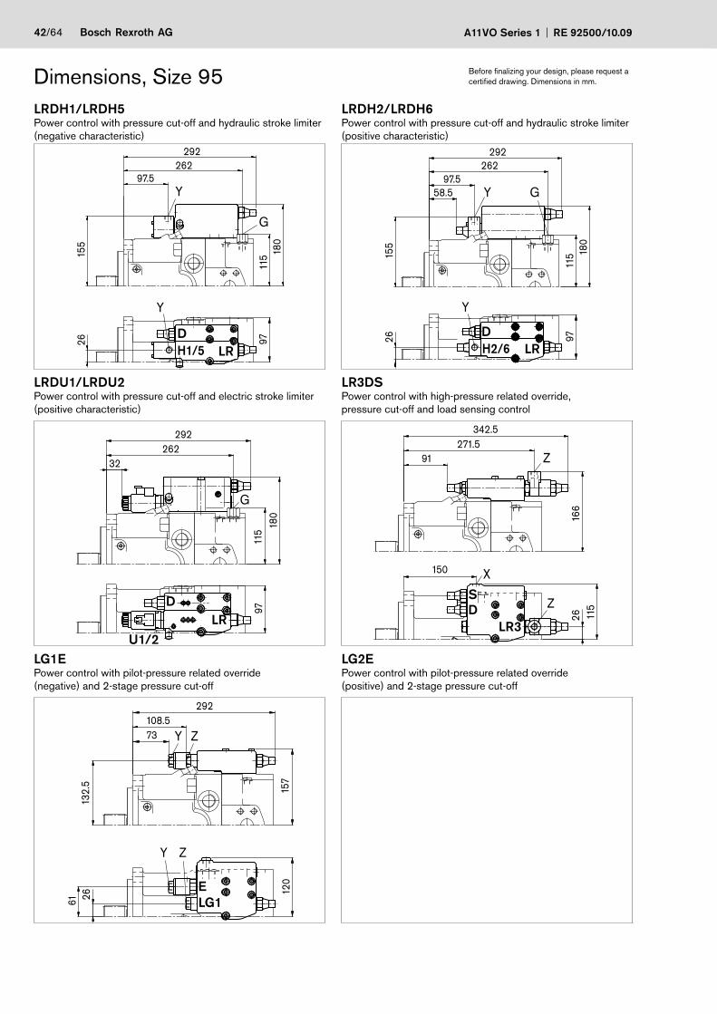
42/64 Bosch Rexroth AG A11VO Series 1 RE 92500/10.09
Dimensions, Size 95 Before finalizing your design, please request a certified drawing. Dimensions in mm.
LRDH1/LRDH5Power control with pressure cut-off and hydraulic stroke limiter (negative characteristic)
LRDH2/LRDH6Power control with pressure cut-off and hydraulic stroke limiter (positive characteristic)
Y
Y
G
155
26
115
26297.5
9718
0
292
Y
Y
G
26
262
155
97.5
115
9718
0
292
58.5
LRDU1/LRDU2Power control with pressure cut-off and electric stroke limiter (positive characteristic)
LR3DSPower control with high-pressure related override,pressure cut-off and load sensing control
G
180
115
262
97
292
32
X
Z
Z11
526
15016
6
342.5271.5
91
LG1EPower control with pilot-pressure related override(negative) and 2-stage pressure cut-off
LG2EPower control with pilot-pressure related override(positive) and 2-stage pressure cut-off
Y
Y
Z
Z
61 2613
2.5
108.5
120
292
73
157
DH1/5 LR
DH2/6 LR
DLR
S
LR3D
ELG1
U1/2
RE 92500/10.09 A11VO Series 1 Bosch Rexroth AG 43/64
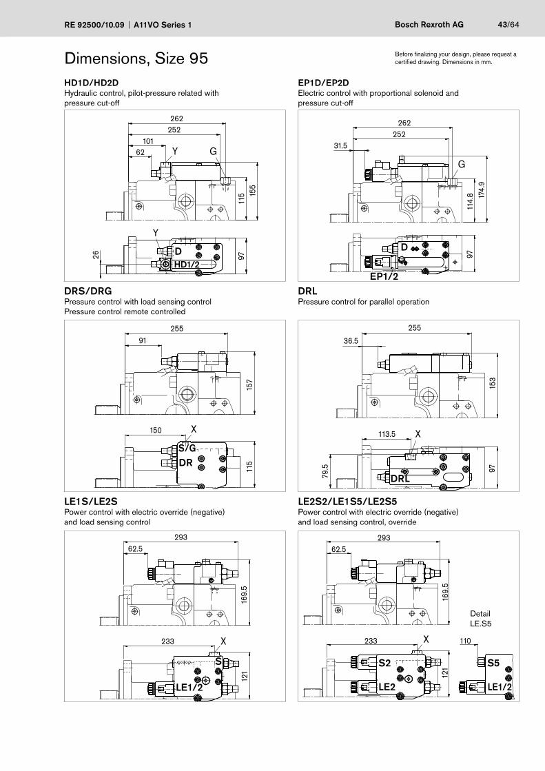
Dimensions, Size 95 Before finalizing your design, please request a certified drawing. Dimensions in mm.
HD1D/HD2DHydraulic control, pilot-pressure related with pressure cut-off
EP1D/EP2DElectric control with proportional solenoid and pressure cut-off
Y
Y
G
26
115
262
101
9715
5
252
62
262252
31.5
174.
911
4.8
97
G
DRS/DRGPressure control with load sensing control Pressure control remote controlled
DRLPressure control for parallel operation
150
115
157
25591
X X113.5
79.5 97
153
255
36.5
LE1S/LE2SPower control with electric override (negative)and load sensing control
LE2S2/LE1S5/LE2S5Power control with electric override (negative)and load sensing control, override
X233
29362.5
121
169.
5
X233 110
29362.5
121
169.
5
DHD1/2
D
S/GDR
DRL
S
EP1/2
LE1/2
S2
LE2
S5
LE1/2
DetailLE.S5
44/64 Bosch Rexroth AG A11VO Series 1 RE 92500/10.09
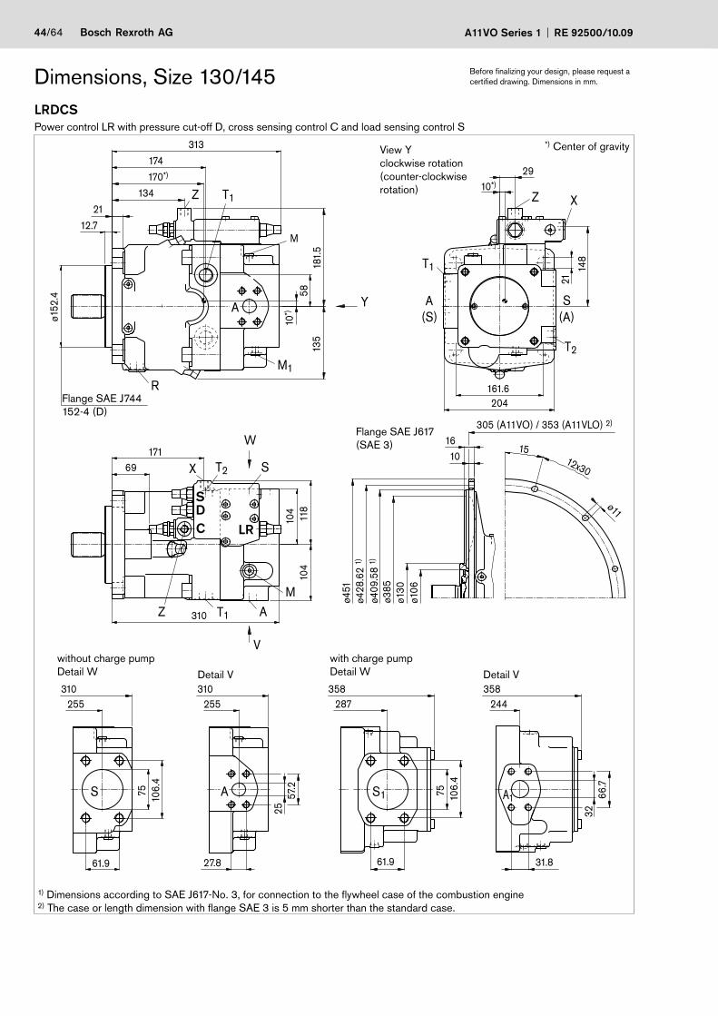
LRDCSPower control LR with pressure cut-off D, cross sensing control C and load sensing control S
Dimensions, Size 130/145 Before finalizing your design, please request a certified drawing. Dimensions in mm.
A1S1
XZ
S(A)
T2
T1
A(S)
Z
Z T1 A
S A
A
M
X T2 S
R
M1
T1
M
15 12x30
ø11
310 358 358
75 106.
4
61.9 31.8
66.7
32
287 244
148
2910*)
181.
513
5
13421
10*)
170*)
57.2
25
27.8
310
ø385
305 (A11VO) / 353 (A11VLO) 2)
ø428
.62
1)ø4
51
ø409
.58
1)
1610
ø106
ø130
255
61.9
106.
475
313
255
174
12.7
204161.6
21
ø152
.4
104
17169
104
118
58Y
W
V
310
1) Dimensions according to SAE J617-No. 3, for connection to the flywheel case of the combustion engine2) The case or length dimension with flange SAE 3 is 5 mm shorter than the standard case.
View Y clockwise rotation (counter-clockwise rotation)
Flange SAE J617(SAE 3)
without charge pumpDetail W Detail V
with charge pumpDetail W Detail V
*) Center of gravity
SDC LR
Flange SAE J744152-4 (D)
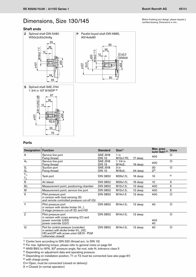
RE 92500/10.09 A11VO Series 1 Bosch Rexroth AG 45/64
Dimensions, Size 130/145Shaft endsZ Splined shaft DIN 5480
W50x2x30x24x9gP Parallel keyed shaft DIN 6885,
AS14x9x80M
16x2
1) 2
)ø1
07
65
ø55
12
36
55
44
ø107
E1x0.2DIN509
M16
x2 1)
2)
90
ø55
12
36
53.5
ø50
82
S Splined shaft SAE J7441 3/4 in 13T 8/16DP 3)
75
ø107
36
55
5/8-
11U
NC
-2B
ø55
67
12
R2.5
Ports
Designation Function Standard Size2) Max. pres-sure (bar) 4) State
A Service line port SAE J518 1 in 400 OFixing thread DIN 13 M12x1.75; 17 deep
A1 Service line port SAE J518 1 1/4 in 400 OFixing thread DIN 13 M14x2; 19 deep
S, Suction port SAE J518 3 in 30 OS1 Fixing thread DIN 13 M16x2; 24 deep 26)
T1,T2
Tank port DIN 3852 M26x1.5; 16 deep 10 5)
R Air bleed DIN 3852 M26x1.5; 16 deep 10 XM1 Measurement point, positioning chamber DIN 3852 M12x1.5; 12 deep 400 XM Measurement point, service line port DIN 3852 M12x1.5; 12 deep 400 XX Pilot pressure port
in version with load sensing (S)and remote controlled pressure cut-off (G)
DIN 3852 M14x1.5 12 deep 400 O
Y Pilot pressure portin version with stroke limiter (H...),2-stage pressure cut-off (E) and HD
DIN 3852 M14x1.5; 12 deep 40 O
Z Pilot pressure portin version with cross sensing (C) andpower override (LR3)power override (LG1)
DIN 3852 M14x1.5; 12 deep
40040
O
G Port for control pressure (controller)in version with stroke limiter (H.., U2),HD and EP with screw union GE10 - PLM(otherwise closed)
DIN 3852 M14x1.5; 12 deep 40 O
1) Center bore according to DIN 332 (thread acc. to DIN 13)2) For max. tightening torque, please refer to general notes on page 643) ANSI B92.1a-1976, 30° pressure angle, flat root, side fit, tolerance class 5 4) Depending on adjustment data and operating pressure5) Depending on installation position, T1 or T2 must be connected (see also page 61)6) with charge pumpO = Open, must be connected (closed on delivery)X = Closed (in normal operation)
Before finalizing your design, please request a certified drawing. Dimensions in mm.
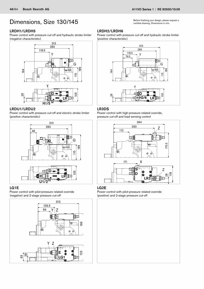
46/64 Bosch Rexroth AG A11VO Series 1 RE 92500/10.09
Dimensions, Size 130/145 Before finalizing your design, please request a certified drawing. Dimensions in mm.
LRDH1/LRDH5Power control with pressure cut-off and hydraulic stroke limiter (negative characteristic)
LRDH2/LRDH6Power control with pressure cut-off and hydraulic stroke limiter (positive characteristic)
105
2816
4 189
115
313283
118.5Y
G
Y
H1/5
105
Y
Y
G
283118.5
164
115
28
189
313
79.5
LRDU1/LRDU2Power control with pressure cut-off and electric stroke limiter (positive characteristic)
LR3DSPower control with high-pressure related override,pressure cut-off and load sensing control
189
115
313283
48
105
G
U1/2
X
Z
Z
171
28
293
118
175.
5
364
112
LG1EPower control with pilot-pressure related override(negative) and 2-stage pressure cut-off
LG2EPower control with pilot-pressure related override(positive) and 2-stage pressure cut-off
Y Z
Y Z
123
63 28
166
313129.594
DLR
DH2/6 LR
DLR
S
LR3D
ELG1
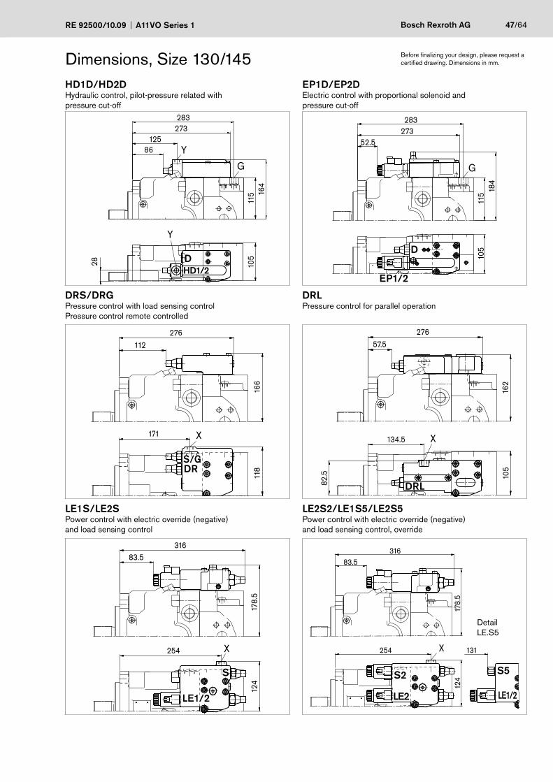
RE 92500/10.09 A11VO Series 1 Bosch Rexroth AG 47/64
Dimensions, Size 130/145 Before finalizing your design, please request a certified drawing. Dimensions in mm.
HD1D/HD2DHydraulic control, pilot-pressure related with pressure cut-off
EP1D/EP2DElectric control with proportional solenoid and pressure cut-off
283273
125
164
28 105
115
86 Y
G
Y
184
115
283273
105
52.5
G
EP1/2
DRS/DRGPressure control with load sensing control Pressure control remote controlled
DRLPressure control for parallel operation
171
118
166
276112
X 134.5
82.5 10
5
276
162
57.5
X
LE1S/LE2SPower control with electric override (negative)and load sensing control
LE2S2/LE1S5/LE2S5Power control with electric override (negative)and load sensing control, override
316
178.
5
83.5
124
254 X
316
178.
5
83.5
124
254 131X
DHD1/2
D
S/GDR
DRL
S
LE1/2
S2
LE2
S5
LE1/2
DetailLE.S5
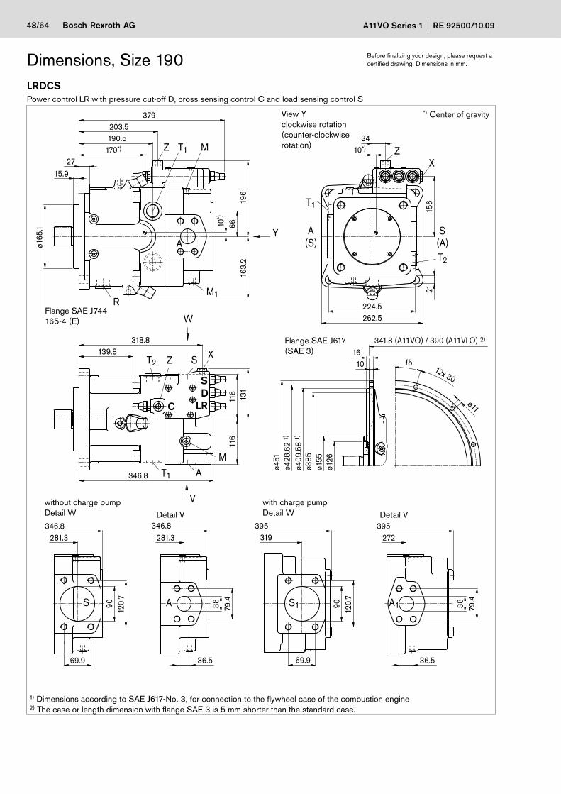
48/64 Bosch Rexroth AG A11VO Series 1 RE 92500/10.09
LRDCSPower control LR with pressure cut-off D, cross sensing control C and load sensing control S
Dimensions, Size 190 Before finalizing your design, please request a certified drawing. Dimensions in mm.
A1S1
Z
S A
ZX
T1
A(S)
T2
(A)S
M
A
Z XT2 S
M1R
T1 M
ø126
ø451
ø409
.58
1)
ø155
ø385
341.8 (A11VO) / 390 (A11VLO) 2)
1610 12x 30
15
ø11
346.8346.8281.3281.3 272
395395319
69.9
120.
790 79
.438
139.8318.8
131
116
116
6616
3.2
196
10*)
170*)
379
ø165
.1
190.5203.5
2715.9
21
262.5224.5
156
3410*)
79.4
38
36.5
120.
790
69.9 36.5
ø428
.62
1)
Y
W
T1 A
V
346.8
1) Dimensions according to SAE J617-No. 3, for connection to the flywheel case of the combustion engine2) The case or length dimension with flange SAE 3 is 5 mm shorter than the standard case.
View Y clockwise rotation (counter-clockwise rotation)
Flange SAE J617(SAE 3)
without charge pumpDetail W Detail V
with charge pumpDetail W Detail V
*) Center of gravity
SD
C LR
Flange SAE J744165-4 (E)
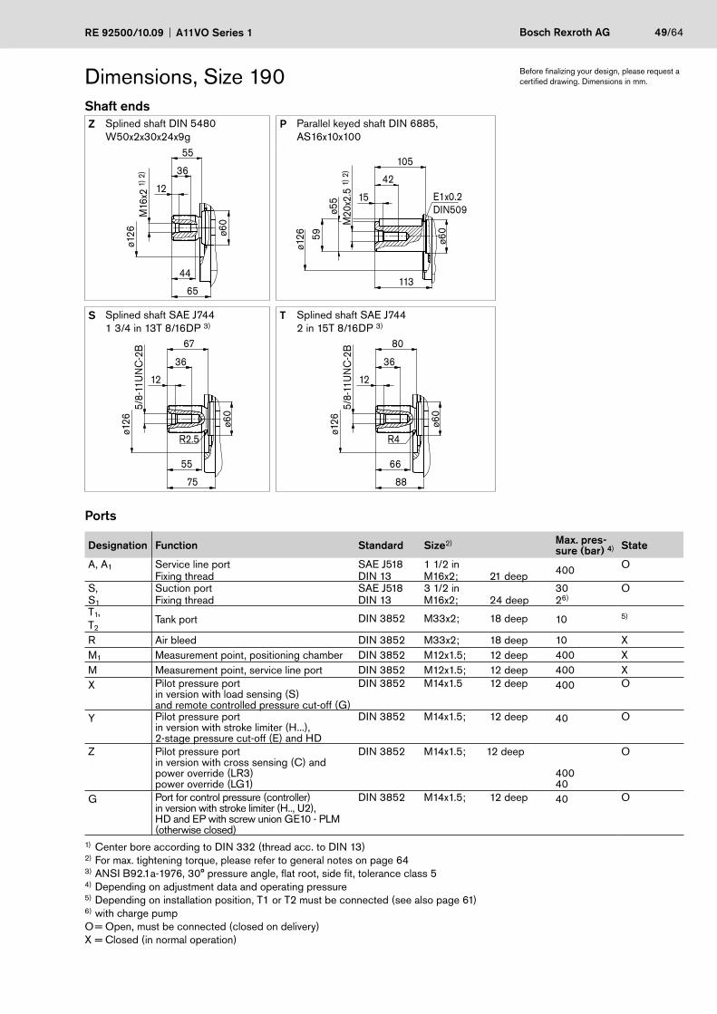
RE 92500/10.09 A11VO Series 1 Bosch Rexroth AG 49/64
Dimensions, Size 190Shaft endsZ Splined shaft DIN 5480
W50x2x30x24x9gP Parallel keyed shaft DIN 6885,
AS16x10x100M
16x2
1) 2
)ø1
26
65
ø60
12
36
55
44
ø126
E1x0.2DIN509
M20
x2.5
1) 2
)
113
ø60
15
42
59
ø55
105
S Splined shaft SAE J7441 3/4 in 13T 8/16DP 3)
T Splined shaft SAE J7442 in 15T 8/16DP 3)
75
ø126
36
55
5/8-
11U
NC
-2B
ø60
67
12
R2.5
88
ø126
36
66
5/8-
11U
NC
-2B
ø60
80
12
R4
Ports
Designation Function Standard Size2) Max. pres-sure (bar) 4) State
A, A1 Service line port SAE J518 1 1/2 in 400 OFixing thread DIN 13 M16x2; 21 deep
S, Suction port SAE J518 3 1/2 in 30 OS1 Fixing thread DIN 13 M16x2; 24 deep 26)
T1,T2
Tank port DIN 3852 M33x2; 18 deep 10 5)
R Air bleed DIN 3852 M33x2; 18 deep 10 XM1 Measurement point, positioning chamber DIN 3852 M12x1.5; 12 deep 400 XM Measurement point, service line port DIN 3852 M12x1.5; 12 deep 400 XX Pilot pressure port
in version with load sensing (S)and remote controlled pressure cut-off (G)
DIN 3852 M14x1.5 12 deep 400 O
Y Pilot pressure portin version with stroke limiter (H...),2-stage pressure cut-off (E) and HD
DIN 3852 M14x1.5; 12 deep 40 O
Z Pilot pressure portin version with cross sensing (C) andpower override (LR3)power override (LG1)
DIN 3852 M14x1.5; 12 deep
40040
O
G Port for control pressure (controller)in version with stroke limiter (H.., U2),HD and EP with screw union GE10 - PLM(otherwise closed)
DIN 3852 M14x1.5; 12 deep 40 O
1) Center bore according to DIN 332 (thread acc. to DIN 13)2) For max. tightening torque, please refer to general notes on page 643) ANSI B92.1a-1976, 30° pressure angle, flat root, side fit, tolerance class 5 4) Depending on adjustment data and operating pressure5) Depending on installation position, T1 or T2 must be connected (see also page 61)6) with charge pumpO = Open, must be connected (closed on delivery)X = Closed (in normal operation)
Before finalizing your design, please request a certified drawing. Dimensions in mm.
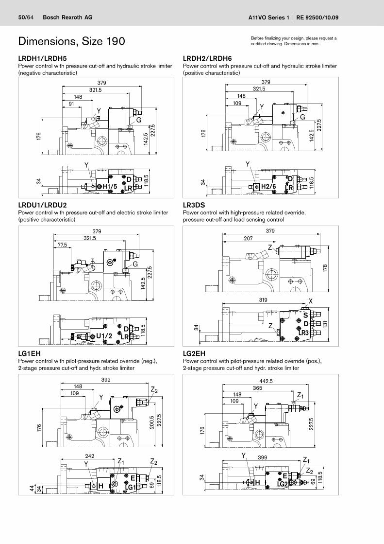
50/64 Bosch Rexroth AG A11VO Series 1 RE 92500/10.09
Dimensions, Size 190 Before finalizing your design, please request a certified drawing. Dimensions in mm.
LRDH1/LRDH5Power control with pressure cut-off and hydraulic stroke limiter (negative characteristic)
LRDH2/LRDH6Power control with pressure cut-off and hydraulic stroke limiter (positive characteristic)
Y
Y
G
34 118.
5
176
321.5148
142.
5 227.
5
379
91 Y
Y
G
34
118.
5
321.5148
142.
5
176 22
7.5
379
109
LRDU1/LRDU2Power control with pressure cut-off and electric stroke limiter (positive characteristic)
LR3DSPower control with high-pressure related override,pressure cut-off and load sensing control
379
227.
514
2.5
321.577.5
118.
5
G
Z
X
Z
319
34 131
178
379207
LG1EHPower control with pilot-pressure related override (neg.),2-stage pressure cut-off and hydr. stroke limiter
LG2EHPower control with pilot-pressure related override (pos.),2-stage pressure cut-off and hydr. stroke limiter
Z2Z1Y
YZ2
200.
5
44 34
242
69
148
176
392
118.
522
7.5
109
Y
Y
Z1
Z1
Z2
399
3417
6
365148
6922
7.5
118.
5
442.5
109
DH1/5 LR
DH2/6 LR
DLR
S
LR3D
ELG1
U1/2
HE
LG2H
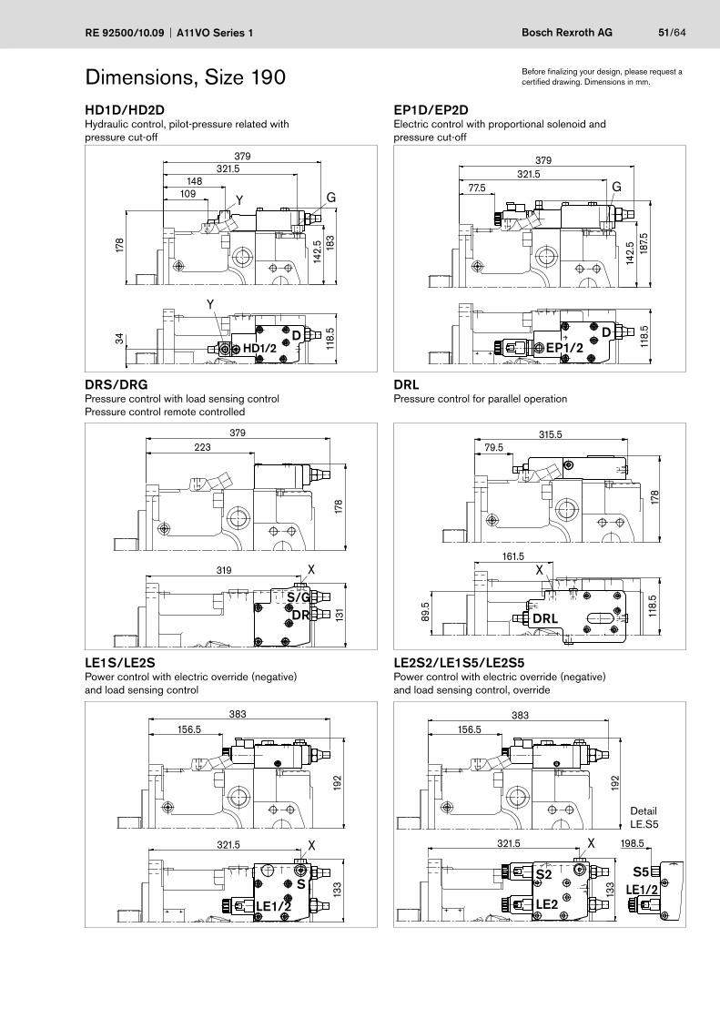
RE 92500/10.09 A11VO Series 1 Bosch Rexroth AG 51/64
Dimensions, Size 190 Before finalizing your design, please request a certified drawing. Dimensions in mm.
HD1D/HD2DHydraulic control, pilot-pressure related with pressure cut-off
EP1D/EP2DElectric control with proportional solenoid and pressure cut-off
Y G
Y
379321.5
148109
118.
5
178
183
142.
5
34 118.
518
7.5
142.
5
379321.5
77.5 G
DRS/DRGPressure control with load sensing control Pressure control remote controlled
DRLPressure control for parallel operation
319
131
178
379223
X X
89.5
161.5
118.
517
8
315.579.5
LE1S/LE2SPower control with electric override (negative)and load sensing control
LE2S2/LE1S5/LE2S5Power control with electric override (negative)and load sensing control, override
133
192
383156.5
321.5 X 198.5
133
192
383156.5
321.5 X
DHD1/2
D
S/GDR DRL
S
EP1/2
LE1/2
S2
LE2
S5LE1/2
DetailLE.S5
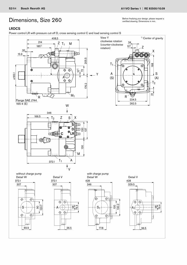
52/64 Bosch Rexroth AG A11VO Series 1 RE 92500/10.09
LRDCSPower control LR with pressure cut-off D, cross sensing control C and load sensing control S
Dimensions, Size 260 Before finalizing your design, please request a certified drawing. Dimensions in mm.
346 329.5428428372.1372.1
307 307
79.4
38
36.5
130.
210
0
77.869.9
120.
790
36.5
79.4
38
130
137
130
166.5346
A1S1AS
T1Z M
M1R
30185*)
10*)
176.
220
5.5
72
408,5214
15.9
ø165
.1 Y
XZ
T1
A(S)
R
T2
S(A)
2116
8
3410*)
262.5224.5
T1
M
ST2
A
A
Z X
W
V
372.1
View Y clockwise rotation (counter-clockwise rotation)
without charge pumpDetail W Detail V
with charge pumpDetail W Detail V
*) Center of gravity
SD
C LR
Flange SAE J744165-4 (E)
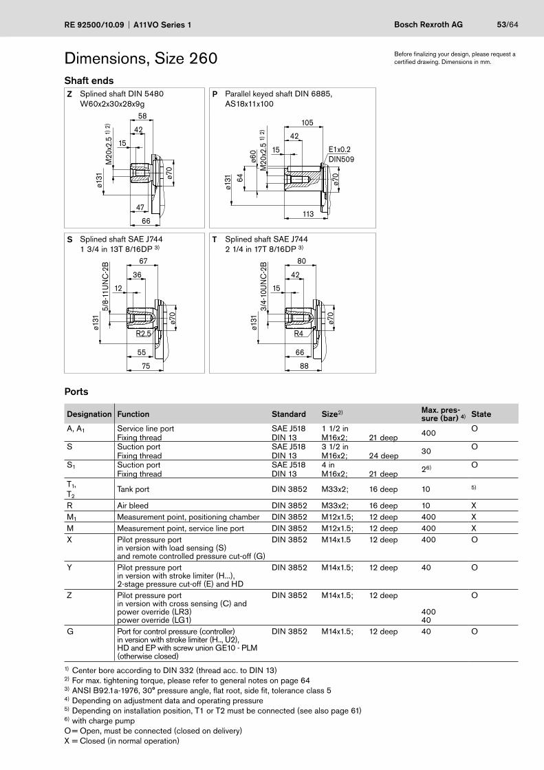
RE 92500/10.09 A11VO Series 1 Bosch Rexroth AG 53/64
Dimensions, Size 260Shaft endsZ Splined shaft DIN 5480
W60x2x30x28x9gP Parallel keyed shaft DIN 6885,
AS18x11x100M
20x2
.5 1)
2)
ø131
66
ø70
15
42
58
47
ø131
E1x0.2DIN509
M20
x2.5
1) 2
)
113
ø70
15
42
64
ø60
105
S Splined shaft SAE J7441 3/4 in 13T 8/16DP 3)
T Splined shaft SAE J744 2 1/4 in 17T 8/16DP 3)
75
ø131
36
55
5/8-
11U
NC
-2B
ø70
67
12
R2.5
88
ø131
42
66
3/4-
10U
NC
-2B
ø70
80
15
R4
Ports
Designation Function Standard Size2) Max. pres-sure (bar) 4) State
A, A1 Service line port SAE J518 1 1/2 in 400 OFixing thread DIN 13 M16x2; 21 deep
S Suction port SAE J518 3 1/2 in 30 OFixing thread DIN 13 M16x2; 24 deep
S1 Suction port SAE J518 4 in 26) OFixing thread DIN 13 M16x2; 21 deep
T1,T2
Tank port DIN 3852 M33x2; 16 deep 10 5)
R Air bleed DIN 3852 M33x2; 16 deep 10 XM1 Measurement point, positioning chamber DIN 3852 M12x1.5; 12 deep 400 XM Measurement point, service line port DIN 3852 M12x1.5; 12 deep 400 XX Pilot pressure port
in version with load sensing (S)and remote controlled pressure cut-off (G)
DIN 3852 M14x1.5 12 deep 400 O
Y Pilot pressure portin version with stroke limiter (H...),2-stage pressure cut-off (E) and HD
DIN 3852 M14x1.5; 12 deep 40 O
Z Pilot pressure portin version with cross sensing (C) andpower override (LR3)power override (LG1)
DIN 3852 M14x1.5; 12 deep
40040
O
G Port for control pressure (controller)in version with stroke limiter (H.., U2),HD and EP with screw union GE10 - PLM(otherwise closed)
DIN 3852 M14x1.5; 12 deep 40 O
1) Center bore according to DIN 332 (thread acc. to DIN 13)2) For max. tightening torque, please refer to general notes on page 643) ANSI B92.1a-1976, 30° pressure angle, flat root, side fit, tolerance class 5 4) Depending on adjustment data and operating pressure5) Depending on installation position, T1 or T2 must be connected (see also page 61)6) with charge pumpO = Open, must be connected (closed on delivery)X = Closed (in normal operation)
Before finalizing your design, please request a certified drawing. Dimensions in mm.
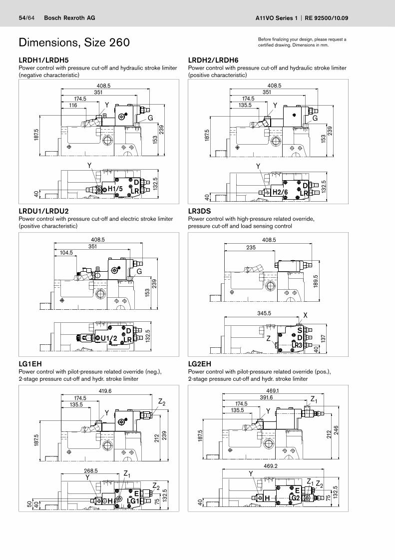
54/64 Bosch Rexroth AG A11VO Series 1 RE 92500/10.09
Dimensions, Size 260 Before finalizing your design, please request a certified drawing. Dimensions in mm.
LRDH1/LRDH5Power control with pressure cut-off and hydraulic stroke limiter (negative characteristic)
LRDH2/LRDH6Power control with pressure cut-off and hydraulic stroke limiter (positive characteristic)
408.5351
174.5116
239
15318
7.5
40
132.
5
G
Y
Y
187.
5
132.
5
40
239
153
408.5351
174.5135.5
G
Y
Y
LRDU1/LRDU2Power control with pressure cut-off and electric stroke limiter (positive characteristic)
LR3DSPower control with high-pressure related override,pressure cut-off and load sensing control
408.5
239
132.
515
3
351104.5
G
40345.5
137
189.
5
408.5235
X
Z
LG1EHPower control with pilot-pressure related override (neg.),2-stage pressure cut-off and hydr. stroke limiter
LG2EHPower control with pilot-pressure related override (pos.),2-stage pressure cut-off and hydr. stroke limiter
212
7550
268.5
419.6174.5
135.5
239
187.
540
132.
5
Y
Z2
Y
Z2
Z1
40
212
75
469.2
469.1391.6
174.5135.5
246
187.
5
132.
5
Y
Y
Z1
Z2Z1
DH1/5 LR
DH2/6 LR
DLR
S
LR3D
ELG1
U1/2
HE
LG2H
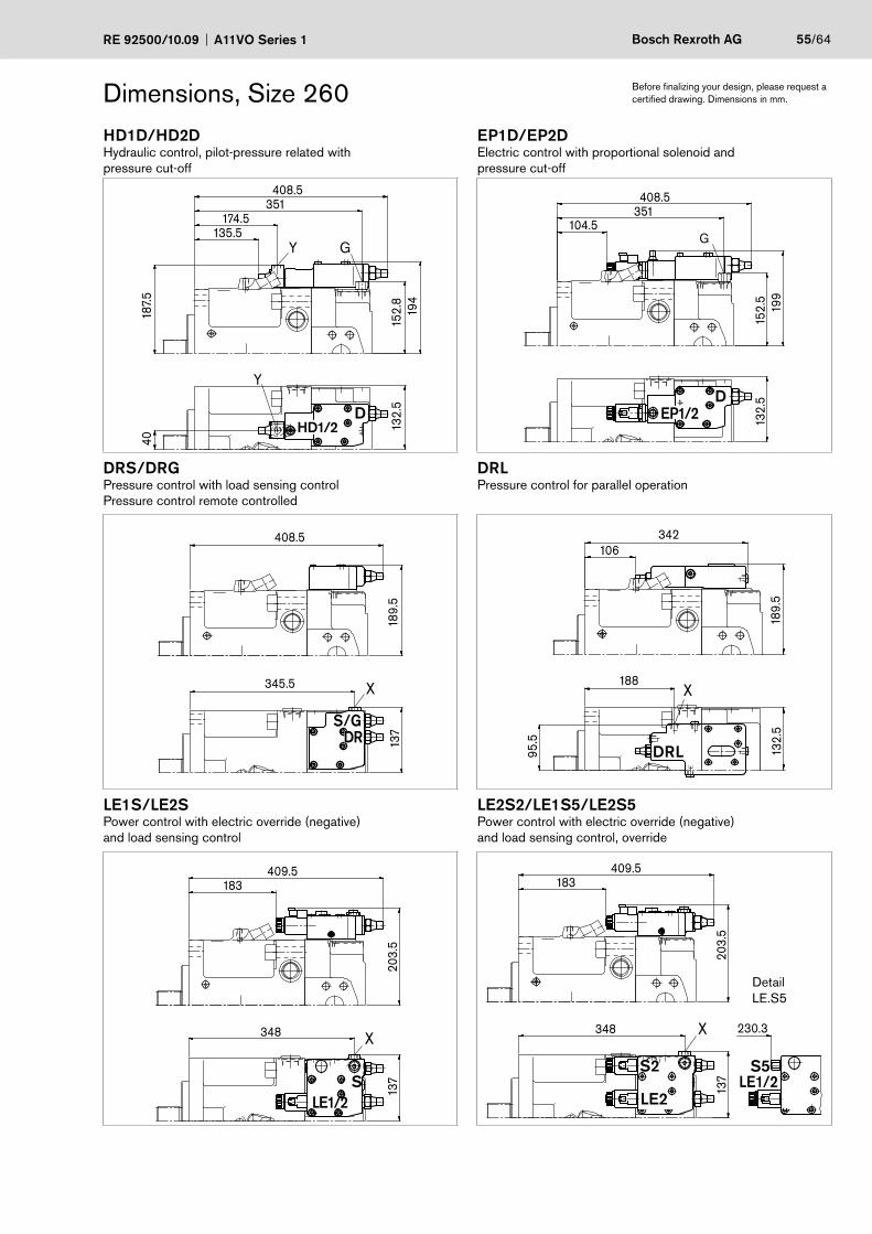
RE 92500/10.09 A11VO Series 1 Bosch Rexroth AG 55/64
Dimensions, Size 260 Before finalizing your design, please request a certified drawing. Dimensions in mm.
HD1D/HD2DHydraulic control, pilot-pressure related with pressure cut-off
EP1D/EP2DElectric control with proportional solenoid and pressure cut-off
187.
540
132.
515
2.8
194
408.5351
174.5135.5
G
Y
Y
132.
519
915
2.5
408.5351
104.5G
DRS/DRGPressure control with load sensing control Pressure control remote controlled
DRLPressure control for parallel operation
345.5
137
408.5
189.
5
X X188
95.5
132.
518
9.5
342106
LE1S/LE2SPower control with electric override (negative)and load sensing control
LE2S2/LE1S5/LE2S5Power control with electric override (negative)and load sensing control, override
203.
5
409.5183
137
348 X
203.
5
409.5183
137
348 230.3X
DHD1/2
D
S/GDR
DRL
S
EP1/2
LE1/2
S2
LE2
S5LE1/2
DetailLE.S5
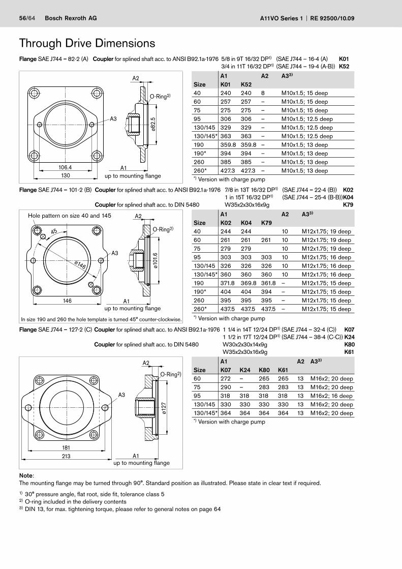
56/64 Bosch Rexroth AG A11VO Series 1 RE 92500/10.09
Through Drive DimensionsFlange SAE J744 – 82-2 (A) Coupler for splined shaft acc. to ANSI B92.1a-1976 5/8 in 9T 16/32 DP1) (SAE J744 – 16-4 (A) K01 3/4 in 11T 16/32 DP1) (SAE J744 – 19-4 (A-B)) K52
A3
A1
ø82.
5
A2
130106.4
O-Ring2)
up to mounting flange
A1 A2 A33)
Size K01 K5240 240 240 8 M10x1.5; 15 deep60 257 257 – M10x1.5; 15 deep75 275 275 – M10x1.5; 15 deep95 306 306 – M10x1.5; 12.5 deep130/145 329 329 – M10x1.5; 12.5 deep130/145* 363 363 – M10x1.5; 12.5 deep190 359.8 359.8 – M10x1.5; 13 deep190* 394 394 – M10x1.5; 13 deep260 385 385 – M10x1.5; 13 deep260* 427.3 427.3 – M10x1.5; 13 deep*) Version with charge pump
Flange SAE J744 – 101-2 (B) Coupler for splined shaft acc. to ANSI B92.1a-1976 7/8 in 13T 16/32 DP1) (SAE J744 – 22-4 (B)) K02 1 in 15T 16/32 DP1) (SAE J744 – 25-4 (B-B)) K04 Coupler for splined shaft acc. to DIN 5480 W35x2x30x16x9g K79
A3
A1
ø146
45
ø101
.6
A2
146
O-Ring2)
Hole pattern on size 40 and 145
up to mounting flange
In size 190 and 260 the hole template is turned 45° counter-clockwise.
A1 A2 A33)
Size K02 K04 K7940 244 244 10 M12x1.75; 19 deep60 261 261 261 10 M12x1.75; 19 deep75 279 279 10 M12x1.75; 19 deep95 303 303 303 10 M12x1.75; 16 deep130/145 326 326 326 10 M12x1.75; 16 deep130/145* 360 360 360 10 M12x1.75; 16 deep190 371.8 369.8 361.8 – M12x1.75; 15 deep190* 404 404 394 – M12x1.75; 15 deep260 395 395 395 – M12x1.75; 15 deep260* 437.5 437.5 437.5 – M12x1.75; 15 deep*) Version with charge pump
Flange SAE J744 – 127-2 (C) Coupler for splined shaft acc. to ANSI B92.1a-1976 1 1/4 in 14T 12/24 DP1) (SAE J744 – 32-4 (C)) K07 1 1/2 in 17T 12/24 DP1) (SAE J744 – 38-4 (C-C)) K24 Coupler for splined shaft acc. to DIN 5480 W30x2x30x14x9g K80 W35x2x30x16x9g K61
A3
A1181213
ø127
A2
O-Ring2)
up to mounting flange
A1 A2 A33)
Size K07 K24 K80 K6160 272 – 265 265 13 M16x2; 20 deep75 290 – 283 283 13 M16x2; 20 deep95 318 318 318 318 13 M16x2; 16 deep130/145 330 330 330 330 13 M16x2; 20 deep130/145* 364 364 364 364 13 M16x2; 20 deep*) Version with charge pump
Note:The mounting flange may be turned through 90°. Standard position as illustrated. Please state in clear text if required.
1) 30° pressure angle, flat root, side fit, tolerance class 52) O-ring included in the delivery contents 3) DIN 13, for max. tightening torque, please refer to general notes on page 64
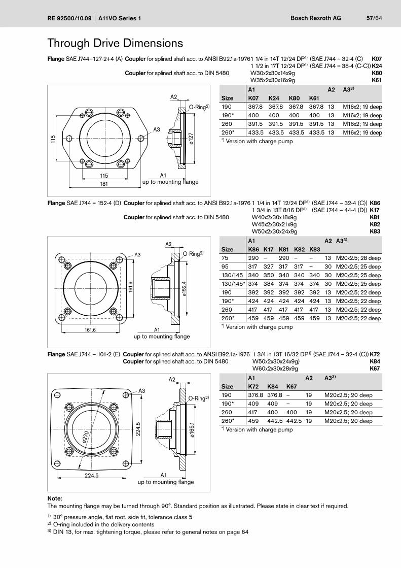
RE 92500/10.09 A11VO Series 1 Bosch Rexroth AG 57/64
Through Drive DimensionsFlange SAE J744–127-2+4 (A) Coupler for splined shaft acc. to ANSI B92.1a-1976 1 1/4 in 14T 12/24 DP1) (SAE J744 – 32-4 (C) K07 1 1/2 in 17T 12/24 DP1) (SAE J744 – 38-4 (C-C)) K24 Coupler for splined shaft acc. to DIN 5480 W30x2x30x14x9g K80 W35x2x30x16x9g K61
A3
A1
115
ø127
A2
115181
O-Ring2)
up to mounting flange
A1 A2 A33)
Size K07 K24 K80 K61190 367.8 367.8 367.8 367.8 13 M16x2; 19 deep190* 400 400 400 400 13 M16x2; 19 deep260 391.5 391.5 391.5 391.5 13 M16x2; 19 deep260* 433.5 433.5 433.5 433.5 13 M16x2; 19 deep*) Version with charge pump
Flange SAE J744 – 152-4 (D) Coupler for splined shaft acc. to ANSI B92.1a-1976 1 1/4 in 14T 12/24 DP1) (SAE J744 – 32-4 (C)) K86 1 3/4 in 13T 8/16 DP1) (SAE J744 – 44-4 (D)) K17 Coupler for splined shaft acc. to DIN 5480 W40x2x30x18x9g K81 W45x2x30x21x9g K82 W50x2x30x24x9g K83
A3
A1
ø152
.4
161.
6
A2
161.6
O-Ring2)
up to mounting flange
A1 A2 A33)
Size K86 K17 K81 K82 K8375 290 – 290 – – 13 M20x2.5; 28 deep95 317 327 317 317 – 30 M20x2.5; 25 deep130/145 340 350 340 340 340 30 M20x2.5; 25 deep130/145* 374 384 374 374 374 30 M20x2.5; 25 deep190 392 392 392 392 392 13 M20x2.5; 22 deep190* 424 424 424 424 424 13 M20x2.5; 22 deep260 417 417 417 417 417 13 M20x2.5; 22 deep260* 459 459 459 459 459 13 M20x2.5; 22 deep*) Version with charge pump
Flange SAE J744 – 101-2 (E) Coupler for splined shaft acc. to ANSI B92.1a-1976 1 3/4 in 13T 16/32 DP1) (SAE J744 – 32-4 (C)) K72 Coupler for splined shaft acc. to DIN 5480 W50x2x30x24x9g) K84 W60x2x30x28x9g K67
A1224.5
A2
ø165
.1
224.
5
ø270
O-Ring2)A3
up to mounting flange
A1 A2 A33)
Size K72 K84 K67190 376.8 376.8 – 19 M20x2.5; 20 deep190* 409 409 – 19 M20x2.5; 20 deep260 417 400 400 19 M20x2.5; 20 deep260* 459 442.5 442.5 19 M20x2.5; 20 deep*) Version with charge pump
Note:The mounting flange may be turned through 90°. Standard position as illustrated. Please state in clear text if required.
1) 30° pressure angle, flat root, side fit, tolerance class 52) O-ring included in the delivery contents 3) DIN 13, for max. tightening torque, please refer to general notes on page 64
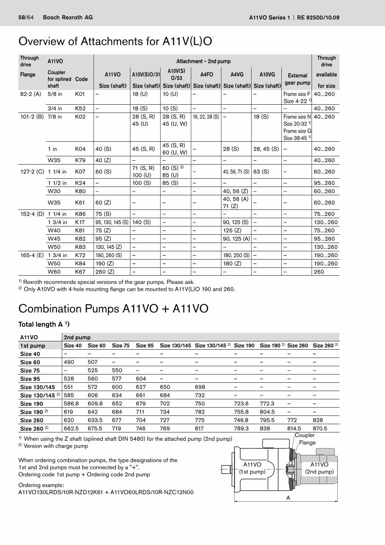
58/64 Bosch Rexroth AG A11VO Series 1 RE 92500/10.09
Overview of Attachments for A11V(L)OThrough drive A11VO Attachment – 2nd pump Through
drive
Flange Coupler for splined shaft
CodeA11VO A10V(S)O/31
A10V(S)O/53
A4FO A4VG A10VG External gear pump
available
Size (shaft) Size (shaft) Size (shaft) Size (shaft) Size (shaft) Size (shaft) for size82-2 (A) 5/8 in K01 – 18 (U) 10 (U) – – – Frame size F
Size 4-22 1)40...260
3/4 in K52 – 18 (S) 10 (S) – – – – 40...260101-2 (B) 7/8 in K02 – 28 (S, R)
45 (U)28 (S, R)45 (U, W)
16, 22, 28 (S) – 18 (S) Frame size NSize 20-32 1)
Frame size GSize 38-45 1)
40...260
1 in K04 40 (S) 45 (S, R)45 (S, R)60 (U, W)
– 28 (S) 28, 45 (S) – 40...260
W35 K79 40 (Z) – – – – – – 40...260
127-2 (C) 1 1/4 in K07 60 (S)71 (S, R)100 (U)
60 (S) 2)
85 (U)– 40, 56, 71 (S) 63 (S) – 60...260
1 1/2 in K24 – 100 (S) 85 (S) – – – – 95...260W30 K80 – – – – 40, 56 (Z) – – 60...260
W35 K61 60 (Z) – – –40, 56 (A)71 (Z)
– – 60...260
152-4 (D) 1 1/4 in K86 75 (S) – – – – – – 75...2601 3/4 in K17 95, 130, 145 (S) 140 (S) – – 90, 125 (S) – – 130...260W40 K81 75 (Z) – – – 125 (Z) – – 75...260W45 K82 95 (Z) – – – 90, 125 (A) – – 95...260W50 K83 130, 145 (Z) – – – – – – 130...260
165-4 (E) 1 3/4 in K72 190, 260 (S) – – – 180, 250 (S) – – 190...260W50 K84 190 (Z) – – – 180 (Z) – – 190...260W60 K67 260 (Z) – – – – – – 260
1) Rexroth recommends special versions of the gear pumps. Please ask.2) Only A10VO with 4-hole mounting flange can be mounted to A11V(L)O 190 and 260.
Combination Pumps A11VO + A11VOTotal length A 1)
A11VO 2nd pump1st pump Size 40 Size 60 Size 75 Size 95 Size 130/145 Size 130/145 2) Size 190 Size 190 2) Size 260 Size 260 2)
Size 40 – – – – – – – – – –Size 60 490 507 – – – – – – – –Size 75 – 525 550 – – – – – – –Size 95 528 560 577 604 – – – – – –Size 130/145 551 572 600 627 650 698 – – – –Size 130/145 2) 585 606 634 661 684 732 – – – –Size 190 586.8 609.8 652 679 702 750 723.6 772.3 – –Size 190 2) 619 642 684 711 734 782 755.8 804.5 – –Size 260 620 633.5 677 704 727 775 746.8 795.5 772 828Size 260 2) 662.5 675.5 719 746 769 817 789.3 838 814.5 870.5
1) When using the Z shaft (splined shaft DIN 5480) for the attached pump (2nd pump)2) Version with charge pump
When ordering combination pumps, the type designations of the 1st and 2nd pumps must be connected by a "+".Ordering code 1st pump + Ordering code 2nd pump
Ordering example:A11VO130LRDS/10R-NZD12K61 + A11VO60LRDS/10R-NZC12N00
A
A11VO(1st pump)
A11VO(2nd pump)
CouplerFlange
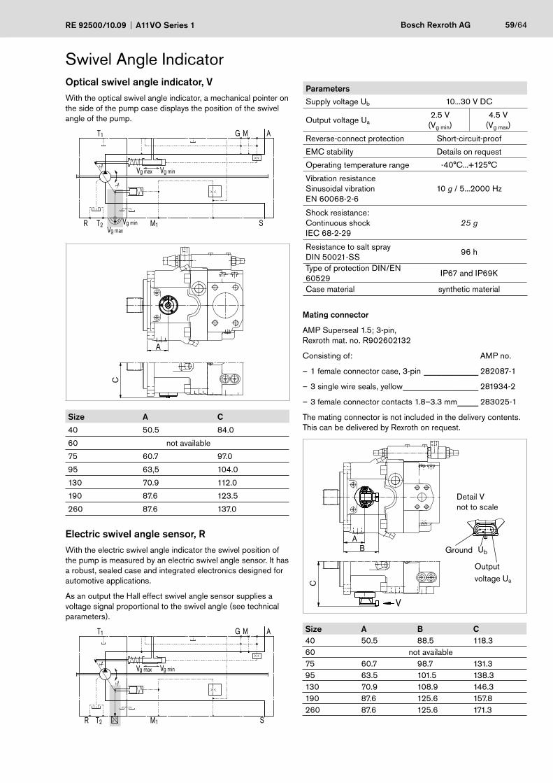
RE 92500/10.09 A11VO Series 1 Bosch Rexroth AG 59/64
Swivel Angle IndicatorOptical swivel angle indicator, VWith the optical swivel angle indicator, a mechanical pointer on the side of the pump case displays the position of the swivel angle of the pump.
g ming maxV
g maxV
V
g minV M1 S
AMGT1
T2R
0
1
C
A
Size A C
40 50.5 84.0
60 not available
75 60.7 97.0
95 63,5 104.0
130 70.9 112.0
190 87.6 123.5
260 87.6 137.0
Electric swivel angle sensor, RWith the electric swivel angle indicator the swivel position of the pump is measured by an electric swivel angle sensor. It has a robust, sealed case and integrated electronics designed for automotive applications.
As an output the Hall effect swivel angle sensor supplies a voltage signal proportional to the swivel angle (see technical parameters).
Uα
T1
T2R
g ming maxV V
M1 S
AMG
Parameters
Supply voltage Ub 10...30 V DC
Output voltage Ua2.5 V
(Vg min)4.5 V
(Vg max)
Reverse-connect protection Short-circuit-proof
EMC stability Details on request
Operating temperature range -40°C...+125°C
Vibration resistanceSinusoidal vibrationEN 60068-2-6
10 g / 5...2000 Hz
Shock resistance:Continuous shockIEC 68-2-29
25 g
Resistance to salt sprayDIN 50021-SS
96 h
Type of protection DIN/EN 60529
IP67 and IP69K
Case material synthetic material
Mating connector
AMP Superseal 1.5; 3-pin,Rexroth mat. no. R902602132
Consisting of: AMP no.
1 female connector case, 3-pin – _____________ 282087-1
3 single wire seals, yellow – __________________ 281934-2
3 female connector contacts 1.8–3.3 mm – _____ 283025-1
The mating connector is not included in the delivery contents. This can be delivered by Rexroth on request.
V
C
BA
Detail Vnot to scale
Outputvoltage Ua
UbGround
Size A B C40 50.5 88.5 118.360 not available75 60.7 98.7 131.395 63.5 101.5 138.3130 70.9 108.9 146.3190 87.6 125.6 157.8260 87.6 125.6 171.3
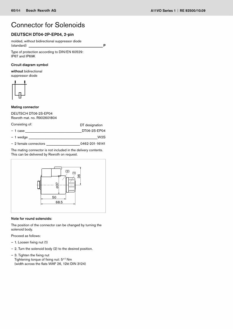
60/64 Bosch Rexroth AG A11VO Series 1 RE 92500/10.09
Connector for SolenoidsDEUTSCH DT04-2P-EP04, 2-pinmolded, without bidirectional suppressor diode(standard) __________________________________________ P
Type of protection according to DIN/EN 60529:IP67 and IP69K
Circuit diagram symbol
without bidirectionalsuppressor diode
Mating connector
DEUTSCH DT06-2S-EP04Rexroth mat. no. R902601804
Consisting of: DT designation
1 – case ________________________________DT06-2S-EP04
1 wedge – _______________________________________W2S
2 female connectors – ___________________ 0462-201-16141
The mating connector is not included in the delivery contents. This can be delivered by Rexroth on request.
36
68.5
Ø37
50
(1)(2)
Note for round solenoids:
The position of the connector can be changed by turning the solenoid body.
Proceed as follows:
1. Loosen fixing nut (1) –
2. Turn the solenoid body (2) to the desired position. –
3. Tighten the fixing nut –Tightening torque of fixing nut: 5+1 Nm(width across the flats WAF 26, 12kt DIN 3124)
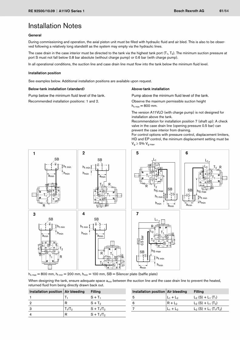
RE 92500/10.09 A11VO Series 1 Bosch Rexroth AG 61/64
Installation NotesGeneral
During commissioning and operation, the axial piston unit must be filled with hydraulic fluid and air bled. This is also to be obser-ved following a relatively long standstill as the system may empty via the hydraulic lines.
The case drain in the case interior must be directed to the tank via the highest tank port (T1, T2). The minimum suction pressure at port S must not fall below 0.8 bar absolute (without charge pump) or 0.6 bar (with charge pump).
In all operational conditions, the suction line and case drain line must flow into the tank below the minimum fluid level.
Installation position
See examples below. Additional installation positions are available upon request.
Below-tank installation (standard)
Pump below the minimum fluid level of the tank.Recommended installation positions: 1 and 2.
Above-tank installation
Pump above the minimum fluid level of the tank.Observe the maximum permissible suction heighths max = 800 mm.
The version A11VLO (with charge pump) is not designed for installation above the tank. Recommendation for installation position 7 (shaft up): A check valve in the case drain line (opening pressure 0.5 bar) can prevent the case interior from draining.For control options with pressure control, displacement limiters, HD and EP control, the minimum displacement setting must be Vg ≥ 5% Vg max.
1 2 5 6
S
R
SB
ht min
hminamin
T1 S
R
T1
T2
SB
ht min
hminamin S
R
T1
T2SB
ht min
hmin amin
L1
hS max
L2
S
R
T1
T2
SB
ht minhminamin
hS max
L2
L1
3 4 7
S
RT1
T2
SB
ht min
hminamin
S
R T1
T2
SB
ht min
hmin amin
S
R
T1
T2
L2
SB
ht min
hminamin
L1
0.5
bar
hS max
hs max = 800 mm, ht min = 200 mm, hmin = 100 mm, SB = Silencer plate (baffle plate)
When designing the tank, ensure adequate space amin between the suction line and the case drain line to prevent the heated, returned fluid from being directly drawn back out.
Installation position Air bleeding Filling Installation position Air bleeding Filling
1 T1 S + T1 5 L1 + L2 L2 (S) + L1 (T1)
2 R S + T2 6 R + L2 L2 (S) + L1 (T2)
3 T1/T2 S + T1/T2 7 L1 + L2 L2 (S) + L1 (T1/T2)
4 R S + T1/T2
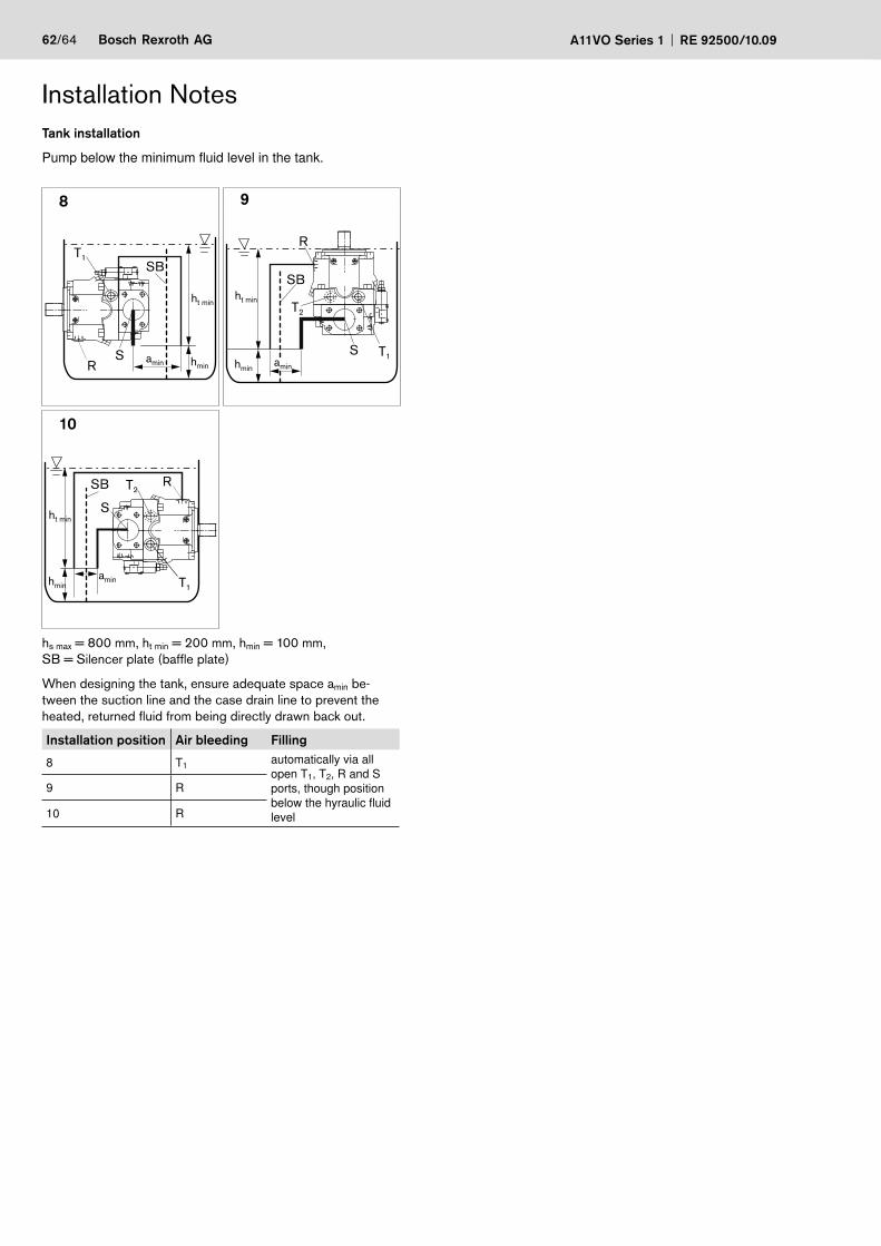
62/64 Bosch Rexroth AG A11VO Series 1 RE 92500/10.09
Installation NotesTank installation
Pump below the minimum fluid level in the tank.
8 9
SB
S hminamin
ht min
T1
R
SB
amin
S T1
R
T2
ht min
hmin
10
SB
S
hminamin
ht min
T2
T1
R
hs max = 800 mm, ht min = 200 mm, hmin = 100 mm,SB = Silencer plate (baffle plate)
When designing the tank, ensure adequate space amin be-tween the suction line and the case drain line to prevent the heated, returned fluid from being directly drawn back out.
Installation position Air bleeding Filling
8 T1 automatically via all open T1, T2, R and S ports, though position below the hyraulic fluid level
9 R
10 R

RE 92500/10.09 A11VO Series 1 Bosch Rexroth AG 63/64
Notice
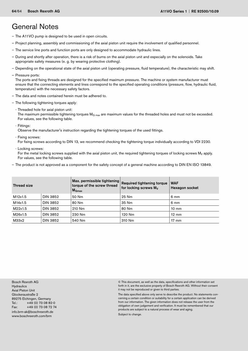
64/64 Bosch Rexroth AG A11VO Series 1 RE 92500/10.09
© This document, as well as the data, specifications and other information set forth in it, are the exclusive property of Bosch Rexroth AG. Without their consent it may not be reproduced or given to third parties.
The data specified above only serve to describe the product. No statements con-cerning a certain condition or suitability for a certain application can be derived from our information. The given information does not release the user from the obligation of own judgement and verification. It must be remembered that our products are subject to a natural process of wear and aging.
Subject to change.
Bosch Rexroth AG HydraulicsAxial Piston Unit Glockeraustraße 2 89275 Elchingen, GermanyTel.: +49 (0) 73 08 82-0Fax: +49 (0) 73 08 72 [email protected] www.boschrexroth.com/brm
The A11VO pump is designed to be used in open circuits. –
Project planning, assembly and commissioning of the axial piston unit require the involvement of qualified personnel. –
The service line ports and function ports are only designed to accommodate hydraulic lines. –
During and shortly after operation, there is a risk of burns on the axial piston unit and especially on the solenoids. Take –appropriate safety measures (e. g. by wearing protective clothing).
Depending on the operational state of the axial piston unit (operating pressure, fluid temperature), the characteristic may shift. –
Pressure ports: –The ports and fixing threads are designed for the specified maximum pressure. The machine or system manufacturer must ensure that the connecting elements and lines correspond to the specified operating conditions (pressure, flow, hydraulic fluid, temperature) with the necessary safety factors.
The data and notes contained herein must be adhered to. –
The following tightening torques apply: –
Threaded hole for axial piston unit: -The maximum permissible tightening torques MG max are maximum values for the threaded holes and must not be exceeded. For values, see the following table.
Fittings: -Observe the manufacturer's instruction regarding the tightening torques of the used fittings.
Fixing screws: -For fixing screws according to DIN 13, we recommend checking the tightening torque individually according to VDI 2230.
Locking screws: -For the metal locking screws supplied with the axial piston unit, the required tightening torques of locking screws MV apply. For values, see the following table.
– The product is not approved as a component for the safety concept of a general machine according to DIN EN ISO 13849.
Thread sizeMax. permissible tightening torque of the screw thread MGmax
Required tightening torque for locking screws MV
WAF Hexagon socket
M12x1.5 DIN 3852 50 Nm 25 Nm 6 mm
M14x1.5 DIN 3852 80 Nm 35 Nm 6 mm
M22x1.5 DIN 3852 210 Nm 80 Nm 10 mm
M26x1.5 DIN 3852 230 Nm 120 Nm 12 mm
M33x2 DIN 3852 540 Nm 310 Nm 17 mm
General Notes