Embed Size (px)
Citation preview
AX-160IP - TOUCH PAD DIGITAL MULTIMETER - USER’SMANUAL
1. GENERAL INSTRUCTIONS
1.0.This instrument complies with IEC 61010-1, CAT III 1000V and CAT IV 600V overvoltage standards. SeeSpecifications.- Touch pad operation.- 6000counts, daul value display.- IP65 water jets.- CAT III 1000V / CAT IV 600V application.- Auto backlight.- Digital calibration.- 2 colour backlight for various operate status indication.- Chargeable battery selection/ MicroUSB chargeTo get the best service from this instrument, please read carefully this user’s manual and respect thedetailed safety precautions.International symbols used on the meter and in this manual are explained in chapter 1.2.
1.1. Precautions safety measures1.1.1. Preliminary* As the possibilities of high transient overvoltages occurred in today’s power systems increase, morestringent safety standards are set for the electrical test equipment. Transients on electrical systems(powergrid, feeder or branch circuits) will trigger a series of incidents that may result in serious personal injury.To protect you against transients, safety must be built into the test equipment.Overvoltage category /// In brief /// Examples- CATI/// Electronic /// • Protected electronic equipment.• Equipment connected to (source) circuits in which measures are taken to limit transient overvoltages toan appropriately low level.• Any high-voltage, low-energy source derived from a highwinding resistance transformer, such as thehigh-voltage section of a copier.- CATII/// Single-phase receptacle connected loads /// • Appliance, portable tools, and other household andsimilar loads.
• Outlet and long branch circuits.• Outlets at more than 10 meters (30 feet) from CAT III source.• Outlets at more that 20 meters (60 feet) from CAT IV source.- CAT III /// Three-phase distribution, including single-phase commercial lighting /// • Equipment in fixedinstallations, such as switchgear and polyphase motors.• Bus and feeder in industrial plants.• Feeders and short branch circuits, distribution panel devices.• Lighting systems in larger buildings.• Appliance outlets with short connections to service entrance.- CAT VI /// Three-phase at utility connection, any outdoor conductors /// • Refers to the “origin of installa-tion”; i.e., where low-voltage connection is made to utility power.• Electricity meters, primary overcurrent protection equipment.• Outside and service entrance, service drop from pole to building, run between meter and panel.• Overhead line to detached building, underground line to well pump.* When using this Multimeter, the user must observe all normal safety rules concerning:� protection against the dangers of electric current.� protection of the Multimeter against misuse.* For your own safety, only use the test probes supplied with the instrument. Before using, check that theyare in good condition.
1.1.2. During using* If the meter is used near noise generating equipment, you should be aware that the display may becomeunstable or indicate large errors.* Do not use the meter or test leads if they are damaged.* Use the meter only as specified in this manual. otherwise, the protection provided by the meter may beimpaired.* Be careful when working around bare conductors or bus bars.* Do not operate the meter around explosive gas, vapor, or dust.* Verify a Meter’s operation by measuring a known voltage. Do not use the Meter if it is abnormally.Protection may be impaired. When you are in doubt ,there is after-sale service.* Use the proper terminals, function, and range for your measurements.* When the range of the value which to be measured is unknown, check that the range initially set on themultimeter is the highest, or you can choose the autoranging mode.* To avoid damages to the instrument, do not exceed the maximum limits of the input values shown in thetechnical specification tables.* When the multimeter is linked to measure circuits, do not touch the terminals which you do not use.* Caution when working with voltages above 60Vdc or 30Vac rms. Such voltages pose a shock hazard.* When using the probes, keep your fingers behind the finger guards.* When making connections, please connect the common test lead before connecting the live test lead; when
disconnecting, disconnect the live test lead before disconnecting the common test lead.* Before changing functions, disconnect the test leads from the circuit under test.* For all DC functions, including manual or auto-ranging, to avoid the risk of shock due to possible improperreading, verify the presence of any AC voltages by first using the AC function. Then select a DC voltagerange equal to or greater than the AC range.* Disconnect circuits power and discharge all high-voltage capacitors before testing resistance, continuity,diodes, or capacitance.* Never perform resistance or continuity measurements on live circuits.* Before measuring current, please check the meter’s fuse and turn off power to the circuit before connectingthe meter to the circuit.* In TV repair work, or when carrying out measurements on power switching circuits, remember that highamplitude voltage pulses at the test points can damage the multimeter. Use of a TV filter will attenuateany such pulses.* Use just 3V battery, properly installed in the Meter’s battery case, to power the Meter.* Replace the battery as soon as the battery indicator ( ) appears. With a low battery, the Meter mightproduce false readings that can lead to electric shock and personal injury.* Do not measure voltages above 1000V in Category III, or 600V in Category IV installations.* When in REL mode, the “REL” symbol is displayed. Caution must be used because hazardous voltagemay be present.* Do not operate the Meter with the case (or part of the case) removed
1.2. Symbols:Symbols used in this manual and on the instrument:
- CAUTION: refer to the instruction manual. Incorrect use may result in damage to the device or itscomponents.
- AC (Alternating Current)- DC (Direct Current)
- AC or DC- Earth ground- Double insulated
- Fuse- Conforms to European Union directives
1.3. Instructions* Remove test leads from the Meter before opening the Meter case or battery cover.* When servicing the Meter, use only specified replacement parts.* Before opening up the instrument, always disconnect from all sources of electric current and make sure
you are not charged with static electricity, which may destroy internal components.* Any adjustment, maintenance or repair work carried out on the meter while it is live should be carried outonly by appropriately qualified personnel, after having taken into account the instructions in this presentmanual.* A ”qualified person” is someone who is familiar with the installation, construction and operation of theequipment and the hazards involved. He is trained and authorized to energize and de-energize circuits andequipment in accordance with established practices.* When the instrument is opened up, remember that some internal capacitors can retain a dangerouspotential even after the instrument is switched off.* If any faults or abnormalities are observed, take the instrument out of service and ensure that it cannotbe used until it has been checked out.* If the meter is not going to be used for a long time, take out the battery and do not store the meter in hightemperature or high humidity environment.
2. DESCRIPTION
2.1. Instrument Familiarization
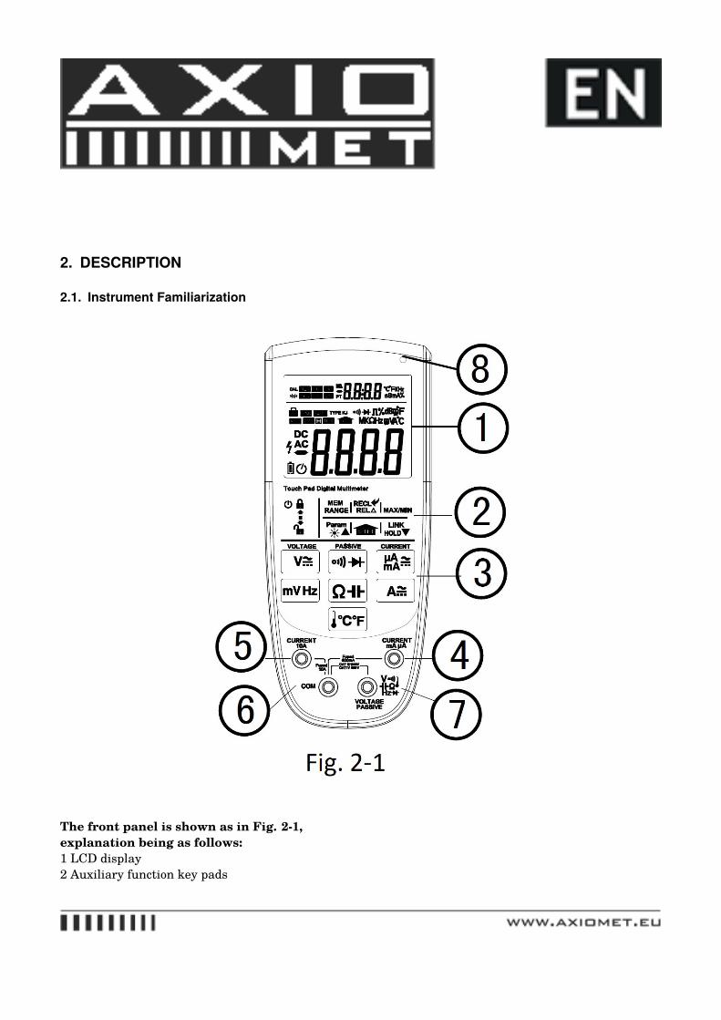
The front panel is shown as in Fig. 2-1,explanation being as follows:1 LCD display2 Auxiliary function key pads
3 Measurement function key pads4 mA / uA socket (uA, mA range red testlead input)5 10A socket (A range red testlead input)6 COM socket (black testlead input)7 V Terminal (red testlead for voltage, resistance, capacitance, frequency, Temperature, diode and conti-nuity measurements)8 Light sensor (Use for auto backlight)
2.2. LCD Display
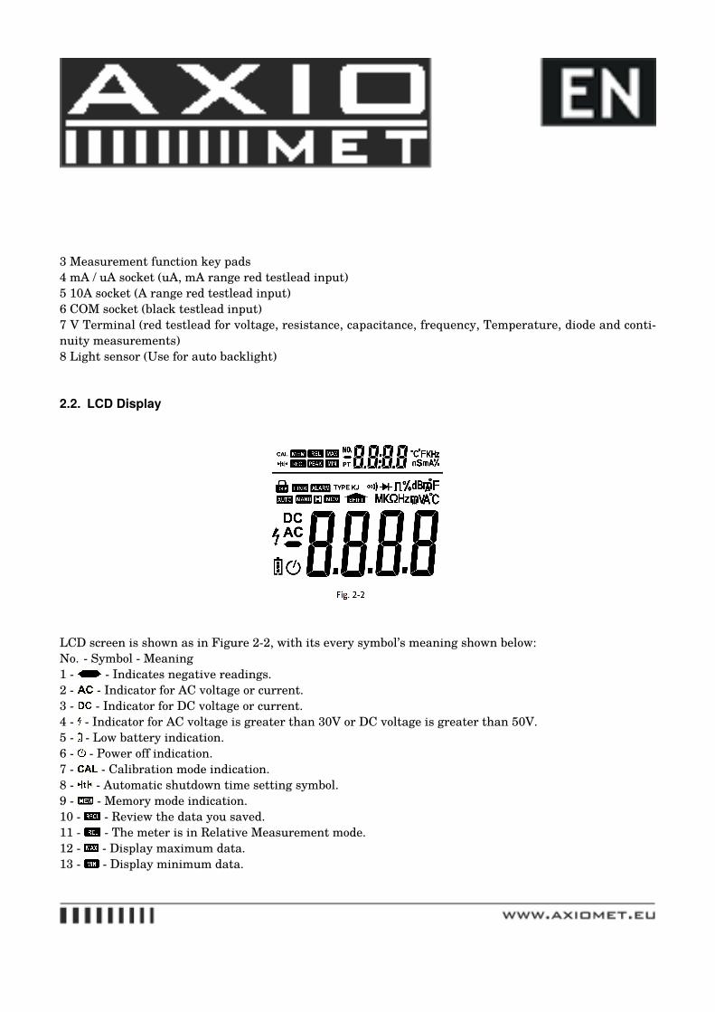
LCD screen is shown as in Figure 2-2, with its every symbol’s meaning shown below:No. - Symbol - Meaning1 - - Indicates negative readings.2 - - Indicator for AC voltage or current.3 - - Indicator for DC voltage or current.4 - - Indicator for AC voltage is greater than 30V or DC voltage is greater than 50V.5 - - Low battery indication.6 - - Power off indication.7 - - Calibration mode indication.8 - - Automatic shutdown time setting symbol.9 - - Memory mode indication.10 - - Review the data you saved.11 - - The meter is in Relative Measurement mode.12 - - Display maximum data.13 - - Display minimum data.
14 - - The number of the data you saved.15 - - Platinum thermal resistance.16 - - Measurement units in the sub-display zone.17 - - Indicates the meter is locked.18 - - The meter is in the Autorange mode in which the meter automatically selects the range with thebest resolution.19 - - The Meter is in the data transmission mode.20 - - The meter is in the manual range mode.21 - - The meter is in Data Hold mode.22 - - Shift key.23 - - The meter is in Continuity Check mode.24 - - The meter is in Diode Test mode.25 - - Transmitter mA current test.26 - - Measurement units.27 - - This symbol means that the input is out of range.
2.3. Touch pad
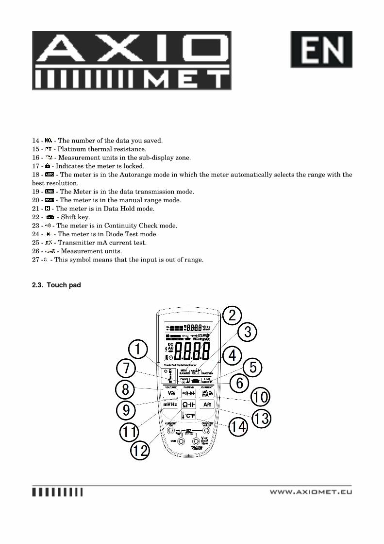
Number -- Explanation1 -- 1.Slide this key to lock or unlock the digital multimeter.2.Slide down this key we can turn on the machine.3.Slide up this key twice quickly, we can turn off the meter.2 -- When you measure the voltage, resistance or current.1.Touch RANGE 2 once to enter the manual ranging mode.2.Touch the key 7 , we can see the range of the measurement will be from large to small.3.Touch the key 5 , we can see the range of the measurement will be from small to large.4.Touch RANGE 2 again to exit autoranging mode.3 -- 1.Touch the key 3 to enter and exit the Relative measurement mode. (in addition to frequency and dutycycle)4 -- 1.Touch the key 4 once, the LCD will display the maximum Value.2.Touch the key 4 twice, the LCD will display the minimum Value.3.Touch this key again to exit.5 -- 1.Touch it to enter the Data Hold mode. And then touch it again to exit this function.2.Touch the key 6, then touch the key 5 to enter the data transmittion mode. Touch the key 5 again to exitthis function.3. At the memory mode, touch this key to pagedown.6 -- 1.Shift key.2.This key will be used to some key combination. It will be describled in detail later.7 -- 1.In general, touch this key to turn on the backlight. Touch it again to turn off it.2.At the memory mode, touch this key to pageup.8 -- 1.Touch this key to measure AC or DC voltage.9 -- 1.Touch this key to enter the continuity check mode.2.Touch this key again to enter the diode test mode.10 -- 1.Touch this key to measure the DC current.2.Touch this key twice to measure the AC current.3.Touch this key three times to measure the duty cycle of waveform.11 -- 1.Touch this key to measure mV voltage.2.Touch this key again to measure the frequency.12 -- 1.Touch this key to measure the resistance.2.Touch this key again to measure the capacitance.13 -- 1.Touch this key to measure DC current.2. Touch this key again to measure AC current.14 -- 1.Touch this key to measure the temperature.2.Touch this key again to select the unit.
3. FUNCTION DESCRIPTION
3.1. General Functions3.1.1. DATA HOLD modeData Hold mode makes the meter stop updating the displaying. If you want to exit this mode, you canchange the measurement which you need.1.Touch the key 5 once. Fixes the display on the current value, the symbol H is displayed on the screen.2. A second touch to return the normal mode.NOTE:If you manually change the measurement range after entering the Data Hold modes, the meter exits thismode.
3.1.2. Manual range and Autorange modeThe meter has both manual range and autorange options.* In the autorange mode, the Meter selects the best range for the input detected. This allows you to switchtest points without having to reset the range.* In the manual range mode, you can select the range. This allows you to override autorange and lock themeter in a specific range.* The meter defaults to the autorange mode in measurement functions that have more than one range.When the Meter is in the autorange mode, the symbol AUTO that is displayed on the screen.To enter and exit the manual range mode:1.Touch RANGE key 2. The meter enters the manual range mode. And then “MANU” will be displayed onthe LCD.2.Touch the key 5 or 7 to select range you neeed.3.Touch RANGE key again to exit. The meter returns to the autorange mode and AUTO is displayed.
3.1.3. Max/Min functionThe Meter will display Maximum or Minimum reading at the sub-display area.Press MAX/MIN key 4 , Maximum reading will display at the sub-display area.Press again MAX/MIN key 4 , Minimum reading will display at the sub-display area.Press again MAX/MIN key 4 , device will escape the MAX/MIN mode.
3.1.4. Relative measurement modeThe Meter will display relative measurement in all functions in addition to frequency.To enter and exit the relative measurement mode:1. With the Meter in the desired function, touch the test leads to the circuit on which you want futuremeasurement to be based.2. Touch REL� key to store the measured value and activate the relative measurement mode. The differ-
ence between the reference value and subsequent reading is displayed.3. Touch REL� key again to return the Meter to normal operation.
3.1.5. Memory modeFor this function,the meter will save the data you need. we can save 10 data at most.To enter and exit the memory mode:1.Touch SHIFT key ,the symbol will be displayed on the screen.2.Touch RANGE key to this mode.3.Touch the key 5 to save the first data, touch it again to save the second data. A total of 10 data can besaved.4.Touch the RANGE key to exit this function.
3.1.6. Review the data1.Touch SHIFT key ,the symbol will be displayed on the screen.2.Touch the key 3 to enter the mode.3.Touch the key 5 or 7 to select the data you need.4.Touch the REL� key to exit this function.
3.1.7. Clear the data1.Touch SHIFT key until the symbol indicated.2.Touch key 7, and then the “clr” symbol indicated.3.Touch the REL� key, the “yes” symbol will be displayed over 2 seconds. After the operation the data willbe cleared.
3.1.8. Data Transmission Mode1.Touch SHIFT key, the symbol indicated.2.Touch the key 5, the “LINK” symbol indicated.3.Touch the key 5 again to exit.* Only exist at D Model.
3.1.9. RMS measurementAll the measurement values of the RMS meter on the AC voltage and AC current are true root-mean-squarevalues. Frequency range from 10~400Hz.
3.1.10. Automatic backlightWhen the light is weak ,the machine will turn on the backlight automatically. You can press the key 7 toturn off the backlight. You can also enter the SET mode to set the threshold of automatic backlight.
3.1.11. Automatic Power offWhen there is no any keys to be pressed, it reached the time you set. The buzzer will ring four times, andthen the device will turn off.1.Turn on the device. And then press the key 6 three times quickly.2.Touch the key 5 or 7 to select the time you want to set. There are 0min(disable the automatic power offfunction), 10min, 30min, 60min, 90min, 120min.3.Touch the key 3, and then touch the key 6 to save the setting.
3.1.12. Automatic Lock TouchPadWhen the measured value is out of the 20% of the range, the touchpad will be locked. And the symbol“LOCK” will flash on the LCD. Until the user unlock the device or the read value dropped to below 20%
3.1.13. Test lead plug IndicationWhen switching the measurement functions need to change the testlead terminal. The symbol “LEAD”will display on the LCD, and the red backlight indicate.
3.1.14. Red Backlight alarmWhen the active measurement is out of range, the red backlight will turn on automatically. It means themeasurement is over the range.
3.1.15. Ambient Temperature measurementWhen the sub-display area has no function, the ambient temperature will be displayed in this area. Forexample, DC voltage, DC current, Diode, CONT, Resistor, Capacitor.
3.1.16. PT100 / PT1000 Temperature measurement1.Touch the key 12 to the resistance measurement mode.2.Touch the key 2, then the symbol “ ” will be displayed on the sub-display.3.Touch the key 7 once to the PT1000.4.Connect the PT100/PT1000 probe to the V terminal and the COM terminal. And the temperature will bedisplayed on the LCD. Types of support are PT100-385 or PT1000-3850, the range is -200 to 850°C�5. Touch the key 7 again to return to the resistance measurement mode.
3.1.17. 4-20mA%, 0-24mA%,0-20mA% measurementWhen you select the DC uA/mA, switch the ranges you can enter the 4-20mA% or 0-24mA% or 0-20mA%.The percentage of current. This function is always using in automatic control area. Such as transmitter,PLC etc. We need to connect the mA terminal and the COM terminal with the output of transmitter.Finally, we can read the value on the LCD.1. Turn on the meter.2. Touch the key 10 three times to enter this function. The symbol “ ” will be shown on the screen.
3. Touch the key 2, the symbol “MANU” will be displayed on the LCD.4. Touch the key 5 or 7 to select the range you need. There are three modes, including 0-20mA%, 0-24mA%, 4-20 mA%.5 Touch the key 10 again to exit.
3.1.18. Sub-display frequency measurementWhen the device is under the AC voltage measurement function, the frequency will be displayed in thesub-display area.
3.1.19. User settings (SET mode)Power up (load battery) the meter, and then press the key 4 “MAX/MIN” 2 times immediately.Then we can enter the SET mode:Set1: Automatic power off time setting.LCD indicate “SET1” at sub-display.You can select: OFF(disable this function), 10min, 30min, 60min, 90min, 120min.Press key 5�or 7� to select the auto power off time.Finish select, press REL key for save the setting.Then press Range key to next setting, or power off device.Set2: The threshold of automatic backlight setting.LCD indicate “SET2” at sub-display, and “LIGH” at main-display.You can place device at a dark environment(or cover the light sensor).Finish select, press REL key for save the setting, LCD show on and backlight on.Then press Range key to next setting, or power off device.Set3: The temperature unit setting.LCD indicate “SET3” at sub-display.You can select: C (centigrade) or F (Fahrenhite).Press key 5�or 7� to select the unit.Finish select, press REL key for save the setting.Then press Range key to next setting, or power off device.Set4: The Ambient temperature calibration.LCD indicate “SET4” at sub-display.You can calibrate the ambient temperature and CJC temperature.Press key 5�or 7� to increase or decrease the temperature. Set it same as the ambient temperature.Short circuit the V-COM terminal.Finish set, press REL key for save the setting. Wait 10second untill LOCK flash again.Then power off device.
3.1.20. Function tablePAD // Default function // Alternate function // Range key selection // Range key reach function
// DC V // - // YES // N/A// - // AC V + Hz // YES // N/A// DC mV // - // YES // N/A// - // AC mV + Hz // YES // N/A// - // Frequency + Duty // N/A // N/A// CONT // - // N/A // N/A// - // DIODE // N/A // N/A// Resistor // - // YES // PT100/PT1000// - // Capacitor // N/A // N/A// Temperature: thermocuple K-type // // N/A // N/A// DC uA/mA // - // YES // N/A// - // AC uA/mA+ Hz // YES // N/A// - // 4~20mA% // 0~24mA%/0~20mA% //// DC A // - // YES // N/A// - // AC A + Hz // YES // N/A
3.2. Measurement Functions3.2.1. AC and DC Voltage measurement3.2.1.1.
To avoid electrical shock and/or damage to the instrument, do not attempt to take any voltagemeasurement that might exceeds 1000Vdc or 1000Vac rms.To avoid electrical shock and/or damage to the instrument, do not apply more than 1000Vdc or1000Vac rms between the common terminal and the earth ground.The Meter’s voltage ranges are 600.0mV, 6.000V, 60.00V, 600.0V and 1000V.To measure ac or dc voltage (set up and connect the Meter as shown in Fig. 3-1):
3.2.1.2. AC VOLTAGE1. Turn on the device.2. Touch the key 8, the meter will enter the ACV range.3. Connect the black and red test leads to the COM and V terminals respectively.4. Connect the test leads to the circuit being measured.5. Read the displayed value.
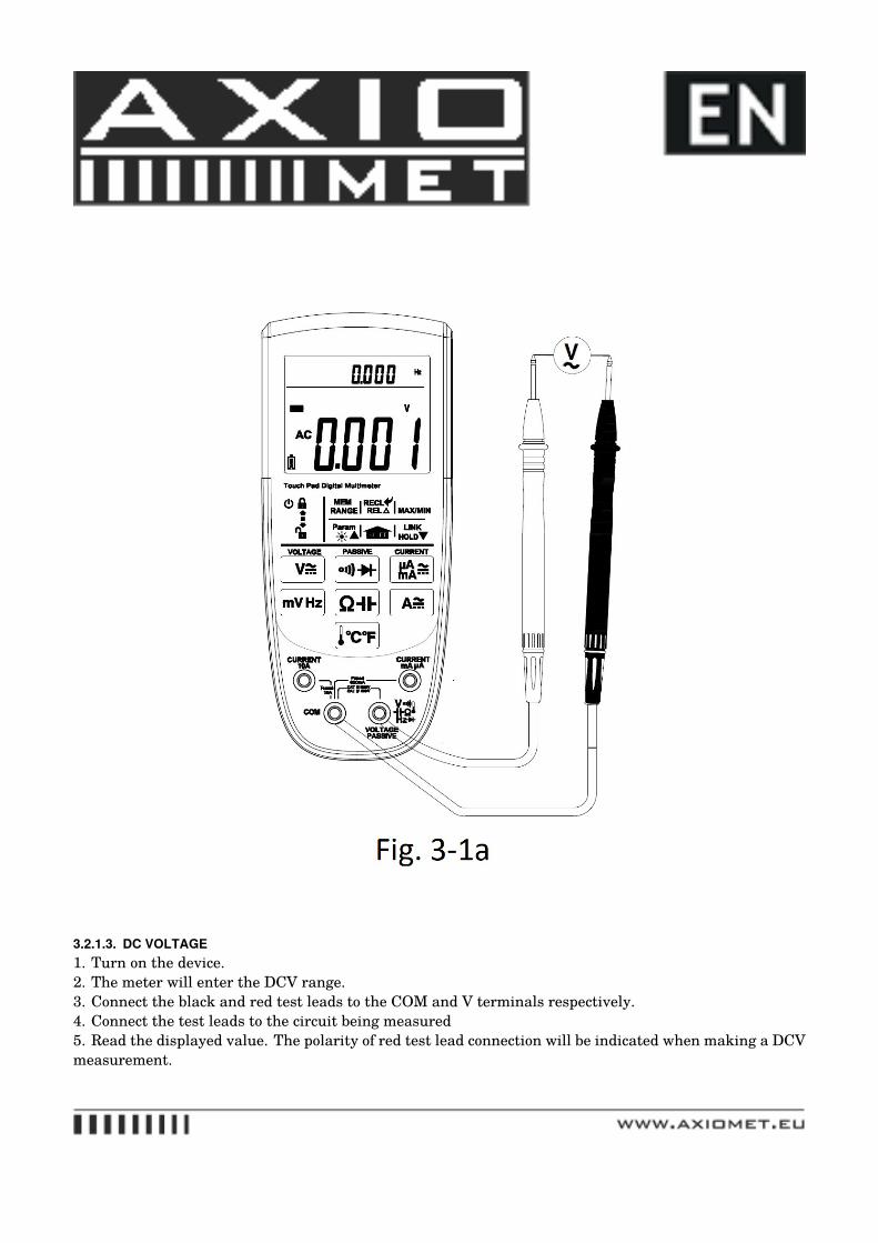
3.2.1.3. DC VOLTAGE1. Turn on the device.2. The meter will enter the DCV range.3. Connect the black and red test leads to the COM and V terminals respectively.4. Connect the test leads to the circuit being measured5. Read the displayed value. The polarity of red test lead connection will be indicated when making a DCVmeasurement.
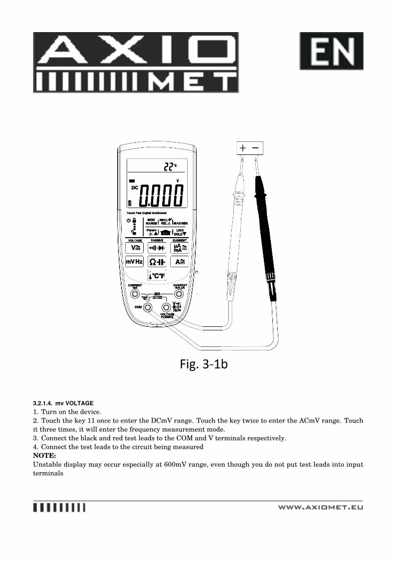
3.2.1.4. mv VOLTAGE1. Turn on the device.2. Touch the key 11 once to enter the DCmV range. Touch the key twice to enter the ACmV range. Touchit three times, it will enter the frequency measurement mode.3. Connect the black and red test leads to the COM and V terminals respectively.4. Connect the test leads to the circuit being measuredNOTE:Unstable display may occur especially at 600mV range, even though you do not put test leads into inputterminals
For better accuracy when measuring the DC offset of an AC voltage, measure the AC voltage first. Notethe AC voltage range, then manually select a DC voltage range
3.2.2. Resistance measurementTo avoid electrical shock and/or damage to the instrument, disconnect circuit power and
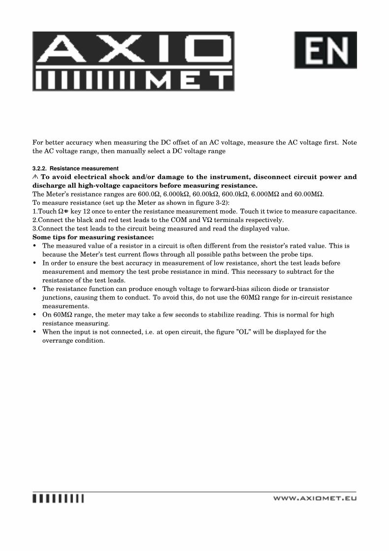
discharge all high-voltage capacitors before measuring resistance.The Meter’s resistance ranges are 600.0Ω, 6.000kΩ, 60.00kΩ, 600.0kΩ, 6.000MΩ and 60.00MΩ.To measure resistance (set up the Meter as shown in figure 3-2):1.Touch Ω key 12 once to enter the resistance measurement mode. Touch it twice to measure capacitance.2.Connect the black and red test leads to the COM and VΩ terminals respectively.3.Connect the test leads to the circuit being measured and read the displayed value.Some tips for measuring resistance:• The measured value of a resistor in a circuit is often different from the resistor’s rated value. This is
because the Meter’s test current flows through all possible paths between the probe tips.• In order to ensure the best accuracy in measurement of low resistance, short the test leads before
measurement and memory the test probe resistance in mind. This necessary to subtract for theresistance of the test leads.
• The resistance function can produce enough voltage to forward-bias silicon diode or transistorjunctions, causing them to conduct. To avoid this, do not use the 60MΩ range for in-circuit resistancemeasurements.
• On 60MΩ range, the meter may take a few seconds to stabilize reading. This is normal for highresistance measuring.
• When the input is not connected, i.e. at open circuit, the figure ”OL” will be displayed for theoverrange condition.
3.2.3. Capacitance measurementTo avoid electrical shock and/or damage to the instrument, disconnect circuit power and dis-
charge all high-voltage capacitors before measuring capacitance. Use the dc voltage function toconfirm that the capacitor is discharged.The Meter’s capacitance ranges are 60.00nF, 600.0µF, 6.000�F, 60.00µF and 300.0µF.
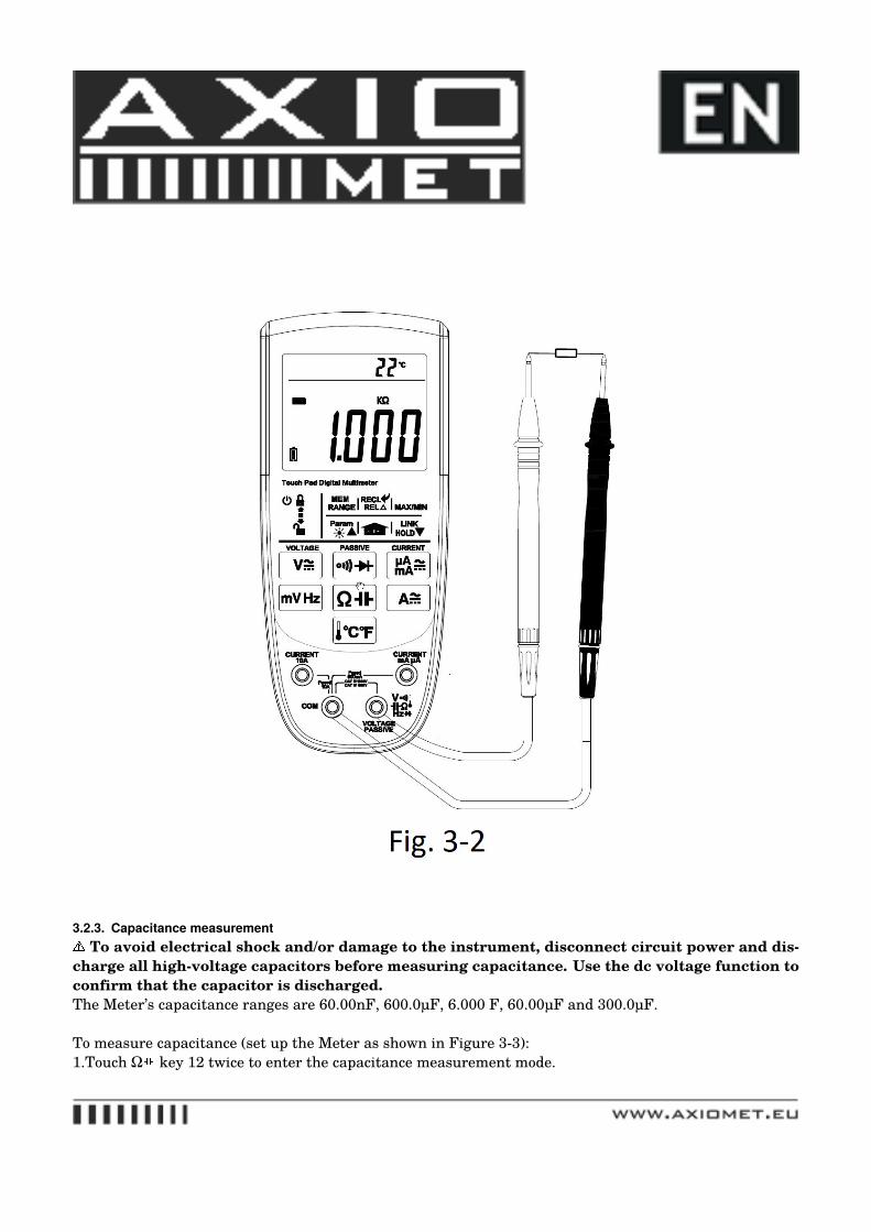
To measure capacitance (set up the Meter as shown in Figure 3-3):1.Touch Ω key 12 twice to enter the capacitance measurement mode.
2. Connect the black and red test leads to the COM and terminals respectively (or you can use capacitortest lead).3. Connect the test leads to the capacitor being measured and read the displayed value.Some tips for measuring capacitance:• The meter may take a few seconds(>30 seconds in 300.0uF range) to stabilize the reading. This is
normal for high capacitance measuring.• To improve the accuracy of measurements less than 60nF, subtract the residual capacitance of the
Meter and leads.• Below 600pF, the accuracy of measurements is unspecified.
3.2.4. Continuity CheckTo avoid electrical shock and/or damage to the instrument, disconnect circuit power and
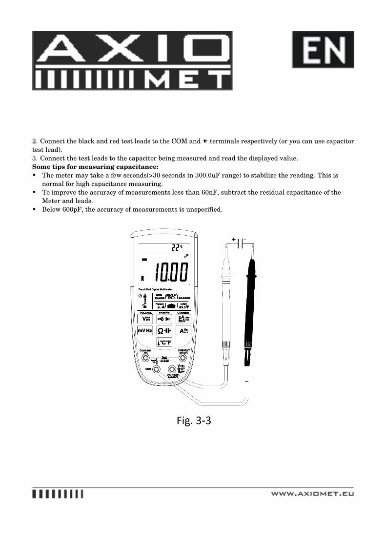
discharge all high-voltage capacitors before testing for Continuity.To test for continuity (set up the Meter as shown in Fig. 3-4):1. Touch the key 9 once to enter the continuity check mode.2. Connect the black and red test leads to the COM and Ω terminals respectively.3. Connect the test leads to the resistance in the circuit being measured.4. When the test lead to the circuit is below 50Ω, the buzzer will sound. And the Red backlight willindication.NOTE:Continuity test is available to check open/short of the circuit.
3.2.5. Diode TestTo avoid electrical shock and/or damage to the instrument, disconnect circuit power and
discharge all high-voltage capacitors before testing diodes.
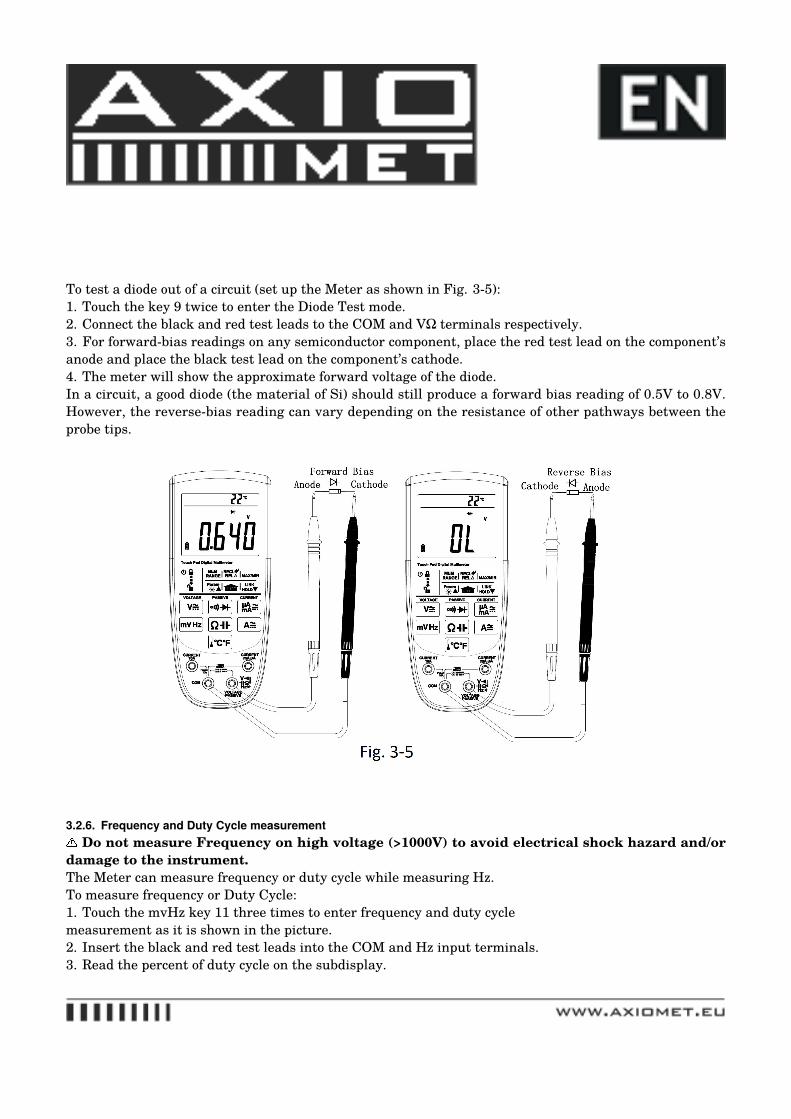
To test a diode out of a circuit (set up the Meter as shown in Fig. 3-5):1. Touch the key 9 twice to enter the Diode Test mode.2. Connect the black and red test leads to the COM and VΩ terminals respectively.3. For forward-bias readings on any semiconductor component, place the red test lead on the component’sanode and place the black test lead on the component’s cathode.4. The meter will show the approximate forward voltage of the diode.In a circuit, a good diode (the material of Si) should still produce a forward bias reading of 0.5V to 0.8V.However, the reverse-bias reading can vary depending on the resistance of other pathways between theprobe tips.
3.2.6. Frequency and Duty Cycle measurementDo not measure Frequency on high voltage (>1000V) to avoid electrical shock hazard and/or
damage to the instrument.The Meter can measure frequency or duty cycle while measuring Hz.To measure frequency or Duty Cycle:1. Touch the mvHz key 11 three times to enter frequency and duty cyclemeasurement as it is shown in the picture.2. Insert the black and red test leads into the COM and Hz input terminals.3. Read the percent of duty cycle on the subdisplay.
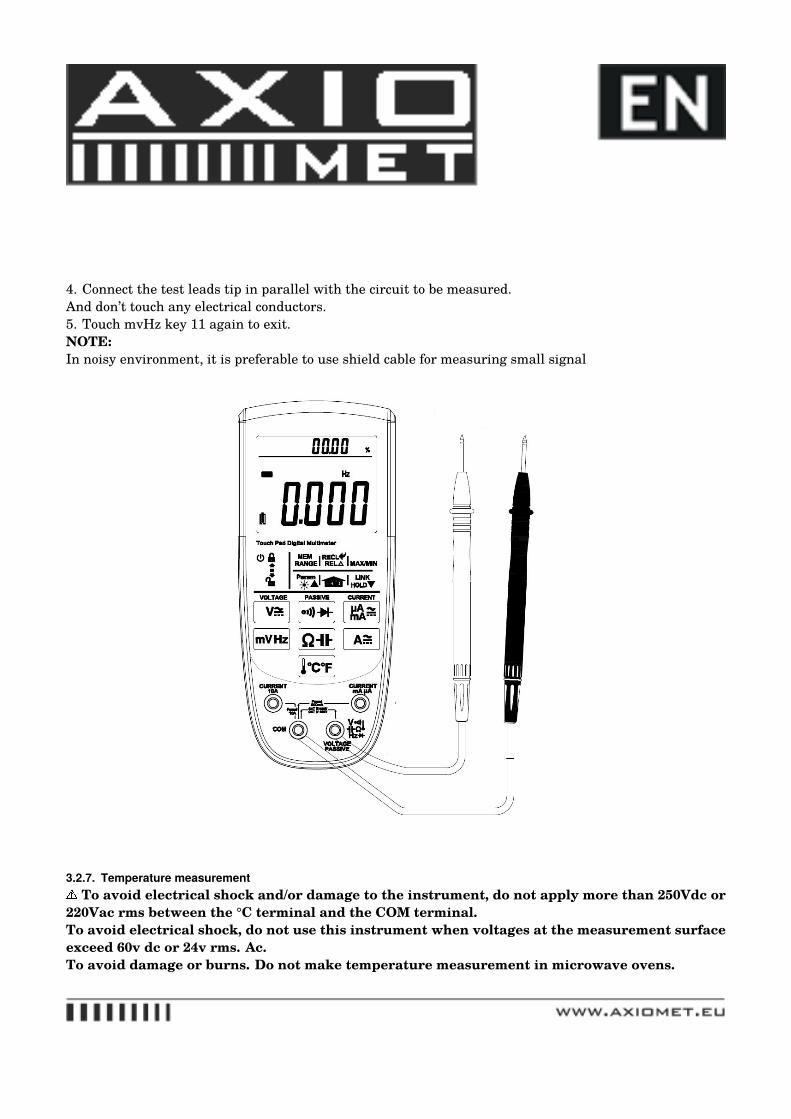
4. Connect the test leads tip in parallel with the circuit to be measured.And don’t touch any electrical conductors.5. Touch mvHz key 11 again to exit.NOTE:In noisy environment, it is preferable to use shield cable for measuring small signal
3.2.7. Temperature measurementTo avoid electrical shock and/or damage to the instrument, do not apply more than 250Vdc or
220Vac rms between the °C terminal and the COM terminal.To avoid electrical shock, do not use this instrument when voltages at the measurement surfaceexceed 60v dc or 24v rms. Ac.To avoid damage or burns. Do not make temperature measurement in microwave ovens.
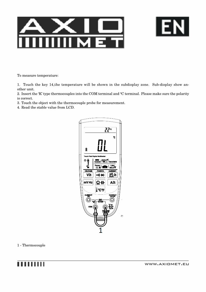
To measure temperature:
1. Touch the key 14,the temperature will be shown in the subdisplay zone. Sub-display show an-other unit.2. Insert the ‘K’ type thermocouples into the COM terminal and ℃ terminal. Please make sure the polarityis correct.3. Touch the object with the thermocouple probe for measurement.4. Read the stable value from LCD.
1 - Thermocouple
3.2.8. Current measurementTo avoid damage to the Meter or injury if the fuse blows, never attempt an in-circuit current
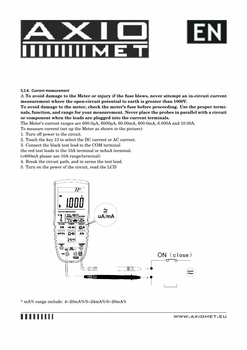
measurement where the open-circuit potential to earth is greater than 1000V.To avoid damage to the meter, check the meter’s fuse before proceeding. Use the proper termi-nals, function, and range for your measurement. Never place the probes in parallel with a circuitor component when the leads are plugged into the current terminals.The Meter’s current ranges are 600.0µA, 6000µA, 60.00mA, 600.0mA, 6.000A and 10.00A.To measure current (set up the Meter as shown in the picture):1. Turn off power to the circuit.2. Touch the key 13 to select the DC current or AC current.3. Connect the black test lead to the COM terminalthe red test leads to the 10A terminal or mAuA terminal.(>600mA please use 10A range/terminal)4. Break the circuit path, and in series the test lead.5. Turn on the power of the circuit, read the LCD
* mA% range include: 4~20mA%/0~24mA%/0~20mA%
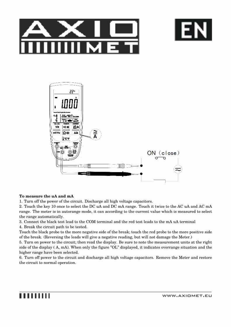
To measure the uA and mA1. Turn off the power of the circuit. Discharge all high voltage capacitors.2. Touch the key 10 once to select the DC uA and DC mA range. Touch it twice to the AC uA and AC mArange. The meter is in autorange mode, it can according to the current value which is measured to selectthe range automatically.3. Connect the black test lead to the COM terminal and the red test leads to the mA uA terminal4. Break the circuit path to be tested.Touch the black probe to the more negative side of the break; touch the red probe to the more positive sideof the break. (Reversing the leads will give a negative reading, but will not damage the Meter.)5. Turn on power to the circuit; then read the display. Be sure to note the measurement units at the rightside of the display (�A, mA). When only the figure ”OL” displayed, it indicates overrange situation and thehigher range have been selected.6. Turn off power to the circuit and discharge all high voltage capacitors. Remove the Meter and restorethe circuit to normal operation.
3.3. PC LinkThe meter has serial data transmission function. It can be connected with PC by USB interface, so themeasured data can be recorded, analyzed, processed and printed by PC. Before using this function, youneed to install the PC-Link software and USB driver in your PC.1.Touch the key 6, the symbol “ ”will be displayed on the LCD.2. Touch the key 5, the meter enter PC-Link mode. The symbol “LINK” will appear on the LCD, and theserial data output function is active.3. Touch the key 5 again to exit.* Only exist at Model DPC-LINK SOFT OPERATING MANUALPlease check the software manual for more information.
4. TECHNICAL SPECIFICATIONS
4.1. General specificationsEnvironment conditions:1000V CAT III and 600V CAT IVPollution degree: 2Altitude < 2000mOperating temperature: 0~40℃, 32°F~122°F(<80% RH, <10℃ non-condensing)Storage temperature: -10~60 ℃, 14°F~140°F(<70% RH, battery removed)Temperature Coefficient: 0.1x(specified accuracy) / ℃ (<18℃ or >28℃)MAX. Voltage between terminals and earth ground: 1000V AC rms or 1000V DC.Fuse Protection: µA and mA: F 0.63A/1000V Ø10.3x38; A: F 10A/1000V Ø10.3x38.Sample Rate: 3 times/sec for digital data.Display: 3 5/6 digits LCD display. Automatic indication of functions and symbols.Range selection: automatic and manual.Over Range indication: LCD will display ”OL”.Low battery indication: The ” ” is displayed when the battery is under the proper operation range.Polarity indication: ”-” displayed automatically.Power source: 3VBattery type: AA*2, or chargeable Lithium battery 3.7V (not included).Dimensions: 190(L)x90(W)x40(H) mm.Weight: 500g. Approx. (battery included).
4.2. Measurement specifications4.2.0.Accuracy is specified for one year after calibration, at operating temperatures of 18℃ to 28℃, with relativehumidity at less than 80%.Accuracy specifications take the form of: ± (% of Reading + Number of Least Significant Digits)
4.2.1. VoltageDCVRange /// Resolution /// Accuracy60mV /// 0.01mV /// ±(0.1% of rdg +5 digits)600mV /// 0.1mV /// ±(0.1% of rdg +2 digits)6V /// 1mV /// ±(0.15% of rdg +2 digits)60V /// 10mV /// ±(0.15% of rdg +2 digits)600V /// 100mV /// ±(0.15% of rdg +2 digits)1000V /// 1V /// ±(0.15% of rdg +2 digits)ACVRange /// Resolution /// Accuracy60mV /// 0.01mV /// ±(0.8% of rdg +10 digits)600mV /// 0.1mV /// ±(0.8% of rdg + 3 digits)6V /// 1mV /// ±(0.8% of rdg + 3 digits)60V /// 10mV /// ±(0.8% of rdg + 3 digits)600V /// 100mV /// ±(0.8% of rdg + 3 digits)1000V /// 1V /// ±(0.8% of rdg + 5 digits)Above accuracies can be guaranteed within 5%~100% of the full range.The true RMS meter has residual value within 10 counts when the test leads are shorten, but that will notaffect the accuracy of measurement.1. Frequency Range for ACV: 40Hz~400Hz.2. Response for ACV: RMS, calibrated in rms of sine wave.3. Overload Protection: 1000V dc or 1000V ac rms.4. Input Impedance (Nominal): DC voltage: >10MΩ; AC voltage: >10MΩ5. <100counts Frequency will not display. (@60mV range <30.00mV)
4.2.2. FrequencyLogic frequency (1Hz-1MHz)Range /// Resolution /// Accuracy9.999Hz /// 0.001Hz /// ±(0.1% of rdg+3digits)99.99Hz /// 0.01 Hz /// ±(0.1% of rdg+3digits)999.9Hz /// 0.1 Hz /// ±(0.1% of rdg+3digits)9.999kHz /// 0.001kHz /// ±(0.1% of rdg+3digits)
99.99kHz /// 0.01kHz /// ±(0.1% of rdg+3digits)999.9kHz /// 0.1kHz /// ±(0.1% of rdg+3digits)Linear frequency (6HZ~10KHZ)Range /// Resolution /// Accuracy99.99Hz /// 0.01 Hz /// ±(0.05% of rdg+5digits)999.9Hz /// 0.1 Hz /// ±(0.05% of rdg+5digits)9.999kHz /// 0.001kHz /// ±(0.05% of rdg+5digits)Above accuracies can be guaranteed within 10%~100% of the full range.
4.2.3. ResistanceRange /// Resolution /// Accuracy600.0Ω /// 0.1 /// ±(0.5% of rdg+3 digits)6.000k /// 1 /// ±(0.5% of rdg+3 digits)60.00k /// 10 /// ±(0.5% of rdg+3 digits)600.0k /// 100 /// ±(0.5% of rdg+3 digits)6.000M /// 1k /// ±(0.5% of rdg+3 digits)60.00M /// 10k /// ±(1.5% of rdg+5 digits)PT100 /// 0.4℃ /// -200~850℃ ±(1.0% of rdg+ 1℃)PT1000 /// 0.4℃ /// -200~850℃ ±(1.0% of rdg+ 1℃)
4.2.4. Diode TestRange /// Resolution /// Test Condition3 V /// 0.001V /// Forward DC current approximately 1mA. Reversed DC voltage approximately 3V.
4.2.5. Continuity CheckRange /// Resolution /// Test Condition600Ω /// 0.1Ω /// Open circuit voltage: approx. 0.5VDescription: Continuity beeper≤50Ω
4.2.6. CapacitanceRange /// Resolution /// Accuracy6.000nF /// 1pF /// ±(3.0% of rdg +10 digits)60.00nF /// 10pF /// ±(3.0% of rdg +10 digits)600.0nF /// 100pF /// ± (5.0% of rdg+10 digits)6.000µF /// 1nF /// ± (5.0% of rdg+10 digits)60.00µF /// 10nF /// ± (5.0% of rdg+10 digits)600.0µF /// 100nF /// ± (5.0% of rdg+10 digits)6.000mF /// 1uF /// ± (8.0% of rdg+20 digits)60.00mF /// 10uF /// ± (10% of rdg+30 digits) typical
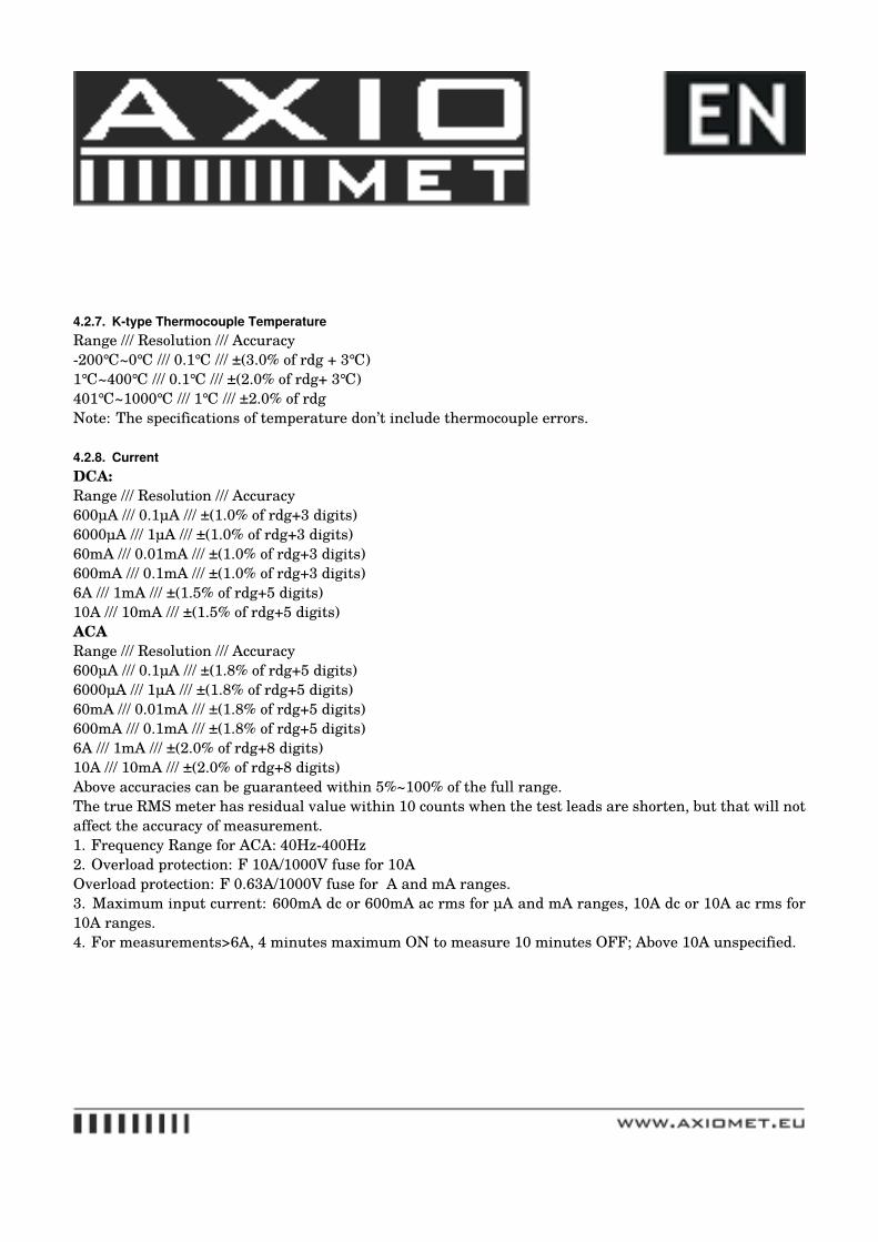
4.2.7. K-type Thermocouple TemperatureRange /// Resolution /// Accuracy-200℃~0℃ /// 0.1℃ /// ±(3.0% of rdg + 3℃)1℃~400℃ /// 0.1℃ /// ±(2.0% of rdg+ 3℃)401℃~1000℃ /// 1℃ /// ±2.0% of rdgNote: The specifications of temperature don’t include thermocouple errors.
4.2.8. CurrentDCA:Range /// Resolution /// Accuracy600µA /// 0.1µA /// ±(1.0% of rdg+3 digits)6000µA /// 1µA /// ±(1.0% of rdg+3 digits)60mA /// 0.01mA /// ±(1.0% of rdg+3 digits)600mA /// 0.1mA /// ±(1.0% of rdg+3 digits)6A /// 1mA /// ±(1.5% of rdg+5 digits)10A /// 10mA /// ±(1.5% of rdg+5 digits)ACARange /// Resolution /// Accuracy600µA /// 0.1µA /// ±(1.8% of rdg+5 digits)6000µA /// 1µA /// ±(1.8% of rdg+5 digits)60mA /// 0.01mA /// ±(1.8% of rdg+5 digits)600mA /// 0.1mA /// ±(1.8% of rdg+5 digits)6A /// 1mA /// ±(2.0% of rdg+8 digits)10A /// 10mA /// ±(2.0% of rdg+8 digits)Above accuracies can be guaranteed within 5%~100% of the full range.The true RMS meter has residual value within 10 counts when the test leads are shorten, but that will notaffect the accuracy of measurement.1. Frequency Range for ACA: 40Hz-400Hz2. Overload protection: F 10A/1000V fuse for 10AOverload protection: F 0.63A/1000V fuse for �A and mA ranges.3. Maximum input current: 600mA dc or 600mA ac rms for µA and mA ranges, 10A dc or 10A ac rms for10A ranges.4. For measurements>6A, 4 minutes maximum ON to measure 10 minutes OFF; Above 10A unspecified.
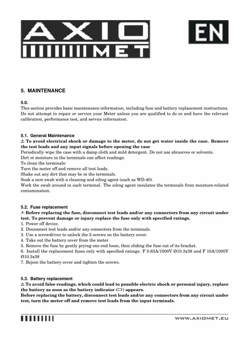
5. MAINTENANCE
5.0.This section provides basic maintenance information, including fuse and battery replacement instructions.Do not attempt to repair or service your Meter unless you are qualified to do so and have the relevantcalibration, performance test, and service information.
5.1. General MaintenanceTo avoid electrical shock or damage to the meter, do not get water inside the case. Remove
the test leads and any input signals before opening the casePeriodically wipe the case with a damp cloth and mild detergent. Do not use abrasives or solvents.Dirt or moisture in the terminals can affect readings.To clean the terminals:Turn the meter off and remove all test leads.Shake out any dirt that may be in the terminals.Soak a new swab with a cleaning and oiling agent (such as WD-40).Work the swab around in each terminal. The oiling agent insulates the terminals from moisture-relatedcontamination.
5.2. Fuse replacementBefore replacing the fuse, disconnect test leads and/or any connectors from any circuit under
test. To prevent damage or injury replace the fuse only with specified ratings.1. Power off device.2. Disconnect test leads and/or any connectors from the terminals.3. Use a screwdriver to unlock the 2 screws on the battery cover.4. Take out the battery cover from the meter.5. Remove the fuse by gently prying one end loose, then sliding the fuse out of its bracket.6. Install the replacement fuses only with specified ratings: F 0.63A/1000V Ø10.3x38 and F 10A/1000VØ10.3x387. Rejoin the battery cover and tighten the screws.
5.3. Battery replacementTo avoid false readings, which could lead to possible electric shock or personal injury, replace
the battery as soon as the battery indicator ( ) appears.Before replacing the battery, disconnect test leads and/or any connectors from any circuit undertest, turn the meter off and remove test leads from the input terminals.
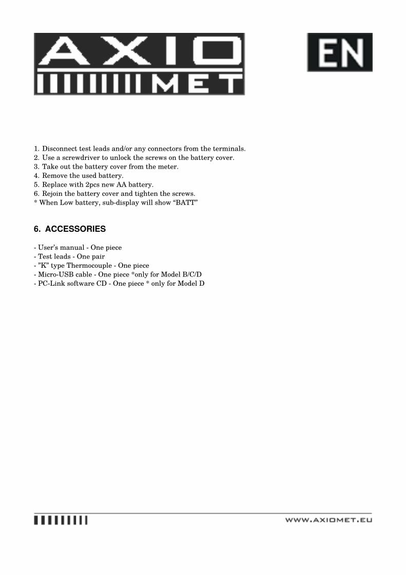
1. Disconnect test leads and/or any connectors from the terminals.2. Use a screwdriver to unlock the screws on the battery cover.3. Take out the battery cover from the meter.4. Remove the used battery.5. Replace with 2pcs new AA battery.6. Rejoin the battery cover and tighten the screws.* When Low battery, sub-display will show “BATT”
6. ACCESSORIES
- User’s manual - One piece- Test leads - One pair- ”K” type Thermocouple - One piece- Micro-USB cable - One piece *only for Model B/C/D- PC-Link software CD - One piece * only for Model D