Embed Size (px)
Citation preview
1
Chemical Engineering Operations
Gas Absorption
Dr. Anand V. PatwardhanProfessor of Chemical EngineeringInstitute of Chemical Technology
Nathalal M. Parekh RoadMatunga (East), Mumbai−400019
Email: [email protected]; [email protected], [email protected]
2
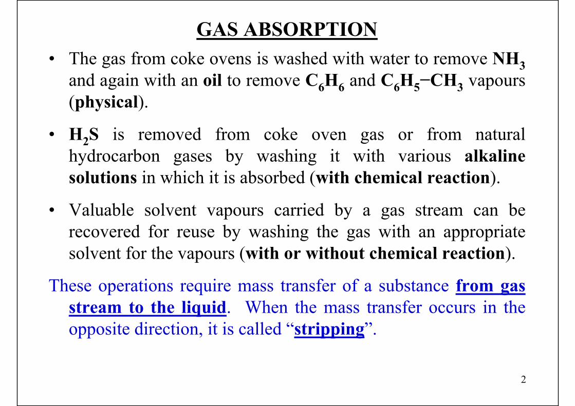
GAS ABSORPTION• The gas from coke ovens is washed with water to remove NH3
and again with an oil to remove C6H6 and C6H5−CH3 vapours (physical).
• H2S is removed from coke oven gas or from natural hydrocarbon gases by washing it with various alkaline solutions in which it is absorbed (with chemical reaction).
• Valuable solvent vapours carried by a gas stream can be recovered for reuse by washing the gas with an appropriate solvent for the vapours (with or without chemical reaction).
These operations require mass transfer of a substance from gas stream to the liquid. When the mass transfer occurs in the opposite direction, it is called “stripping”.
3
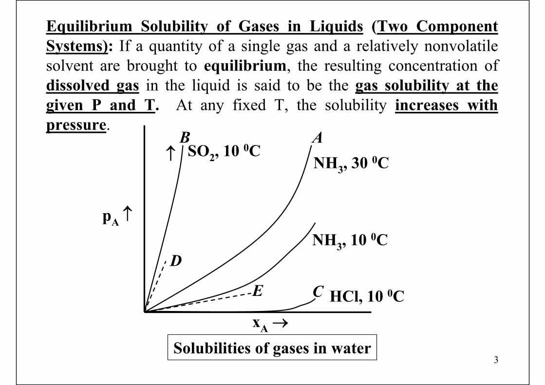
Equilibrium Solubility of Gases in Liquids (Two Component Systems): If a quantity of a single gas and a relatively nonvolatile solvent are brought to equilibrium, the resulting concentration of dissolved gas in the liquid is said to be the gas solubility at the given P and T. At any fixed T, the solubility increases with pressure.
Solubilities of gases in waterxA →
SO2, 10 0CNH3, 30 0C
NH3, 10 0C
HCl, 10 0C
B A↑
pA ↑
D
E C
4
High equilibrium partial pressure of a gas at a given liquid concentration (curve B): relatively insoluble gas,Low equilibrium partial pressure of a gas at a given liquid concentration (curve C): relatively soluble gas
Solubility = f (T), as described by van’t Hoff’s law of mobile equilibrium, ⇒ “If the T of a system at equilibrium is raised, the change will occur in such a way as to absorb the heat”.
Generally, (not always), the solution of a gas results in an evolution of heat, ⇒ the solubility of a gas decreases with increasing T.Exceptionally, the solubility of many low molecular weight gasessuch as H2, O2, N2, CH4, in water increases with increased T above 100 0C, obviously at pressures > 1atmosphere.
5
Multicomponent Systems
Ideal Solutions• If a mixture of gases is brought into contact with a liquid, under
certain conditions, the equilibrium solubilities of each gas will be independent of the others, provided, the equilibrium is described in terms of the partial pressures in the gas mixture.
• If all, except one, components of the gas mixture are very slightly soluble, their concentrations in the liquid will be so small that they cannot influence the solubility of the relatively soluble component.
• For example, absorption of NH3–air mixture into water, provided that the Y-axis is taken to be the partial pressure of NH3 in the mixture.
6
• Even if many components of the gas mixture are significantly soluble, then the ideal solution assumption will be applicable only if the solute gases are indifferent to the nature of liquidand indifferent to each other.
• For example, a mixture of C3H8 and C4H10 dissolved in higher hydrocarbon solvent.
Non−Ideal Solutions• For example, the solubility of NH3 in water is influenced by
the presence of methylamine, and hence the resulting solution of these two gases in water is non−ideal.
• The solubility of a gas is also influenced by the presence of a nonvolatile solute in the solvent, such as a salt, hence these solutions are also non−ideal.
7
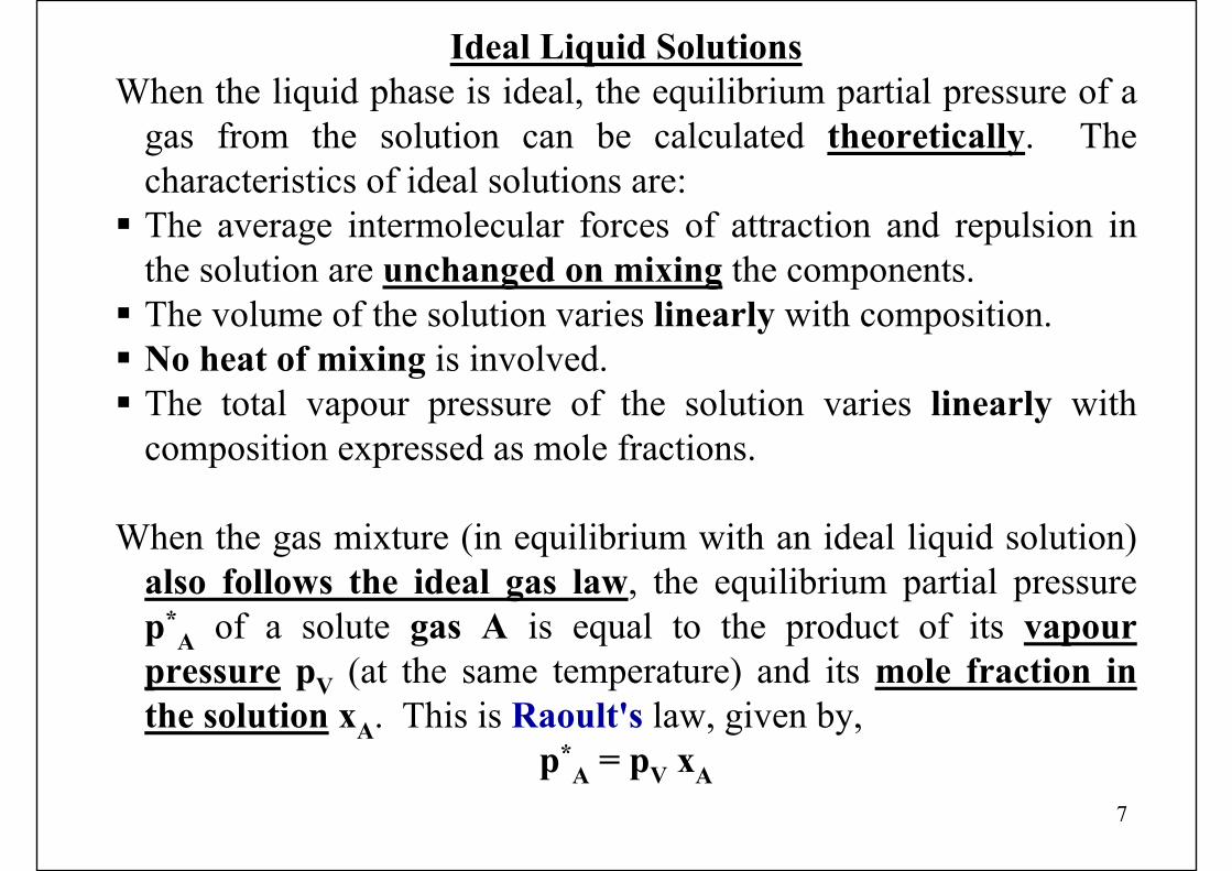
Ideal Liquid SolutionsWhen the liquid phase is ideal, the equilibrium partial pressure of a
gas from the solution can be calculated theoretically. The characteristics of ideal solutions are:The average intermolecular forces of attraction and repulsion inthe solution are unchanged on mixing the components.The volume of the solution varies linearly with composition.No heat of mixing is involved.The total vapour pressure of the solution varies linearly with composition expressed as mole fractions.
When the gas mixture (in equilibrium with an ideal liquid solution) also follows the ideal gas law, the equilibrium partial pressure p*
A of a solute gas A is equal to the product of its vapour pressure pV (at the same temperature) and its mole fraction in the solution xA. This is Raoult's law, given by,
p*A = pV xA
8
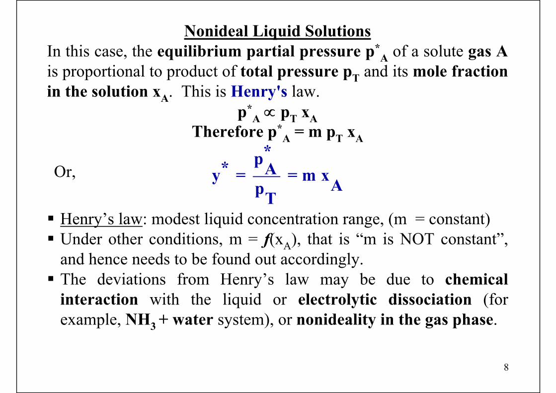
Nonideal Liquid SolutionsIn this case, the equilibrium partial pressure p*
A of a solute gas A is proportional to product of total pressure pT and its mole fraction in the solution xA. This is Henry's law.
p*A ∝ pT xA
Therefore p*A = m pT xA
Or,*p* Ay = = m xApT
Henry’s law: modest liquid concentration range, (m = constant)Under other conditions, m = f(xA), that is “m is NOT constant”, and hence needs to be found out accordingly.The deviations from Henry’s law may be due to chemical interaction with the liquid or electrolytic dissociation (for example, NH3 + water system), or nonideality in the gas phase.

9
Choice of Solvent for Absorption
If absorption is involved for production of a specific product, then the solvent is automatically specified by the nature of the product.If the purpose is to remove some constituent from the gas, some choice is usually available. In that case, following considerations are involved:
1. Gas solubility: should be high.Generally solvents having similar chemical nature as that of solute
will have good solubility. A chemical reaction of solvent (or a component in the solvent) will result in high gas absorption rates, but if the solvent is to be recovered for reuse, the reaction must be reversible. For example:
H2S absorption in alkanolamines (reversible)H2S absorption in alkali (irreversible)
10
2. Volatility: low vapour pressure because the gas leaving absorption equipment is usually saturated with the solvent and this will amount to the loss.
If necessary, a second, less volatile liquid can be used to recover the evaporated portion of the first. For example, in the case of hydrocarbon absorbers, where relatively volatile solvent oil is used in the main absorption operation (due to good solubility criteria), the evaporated solvent is recovered from the vent gas by absorption in nonvolatile oil.
3. Corrosiveness: The MOC required for the equipment should not be uncommon or very expensive.
4. Viscosity: Low viscosity is preferred for higher liquid side mass transfer coefficients, better flooding characteristics of absorption columns, low pressure drops on pumping, and better heat transfer characteristics.
5. Other considerations: AS FAR AS POSSIBLE, It should be nontoxic, nonflammable, chemically stable, and having low freezing point.
11
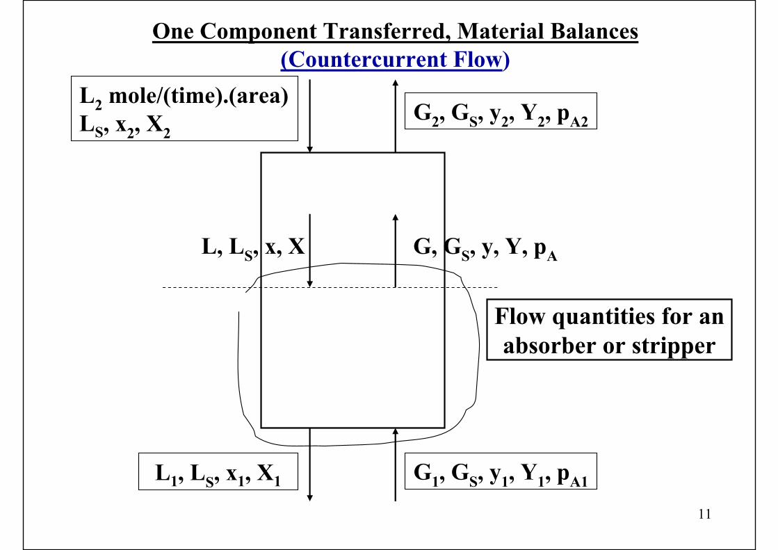
One Component Transferred, Material Balances(Countercurrent Flow)
L2 mole/(time).(area)LS, x2, X2
G2, GS, y2, Y2, pA2
G, GS, y, Y, pAL, LS, x, X
L1, LS, x1, X1 G1, GS, y1, Y1, pA1
Flow quantities for an absorber or stripper
12
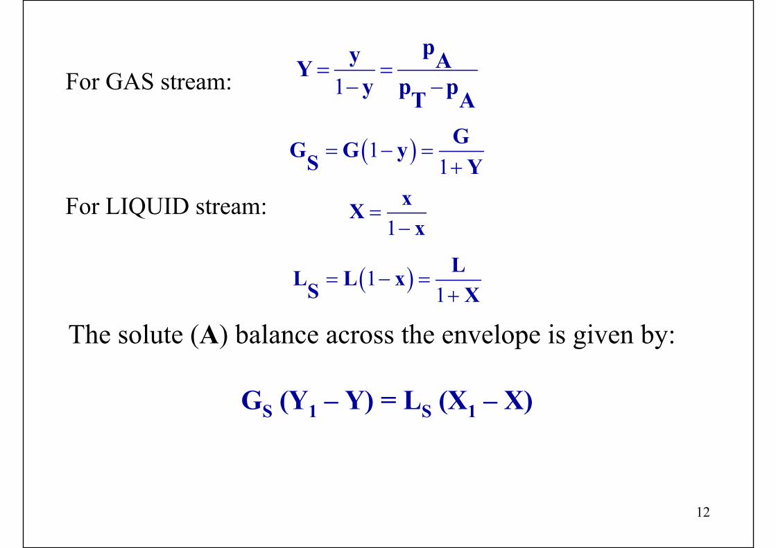
For GAS stream: 1
py AYy p pT A
= =− −
( )11
GG G yS Y= − =
+
For LIQUID stream:1
xXx
=−
( )11
LL L xS X= − =
+
The solute (A) balance across the envelope is given by:
GS (Y1 – Y) = LS (X1 – X)
13
X2 X1 X1 X2
STRIPPER
BOTTOM
TOP
TOP
BOTTOMABSORBER
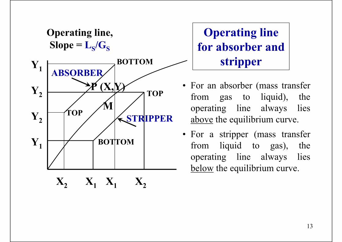
Operating line,Slope = LS/GS
P (X,Y)
M
Y1
Y2
Y2
Y1
• For an absorber (mass transfer from gas to liquid), the operating line always lies above the equilibrium curve.
• For a stripper (mass transfer from liquid to gas), the operating line always lies below the equilibrium curve.
Operating line for absorber and
stripper
14
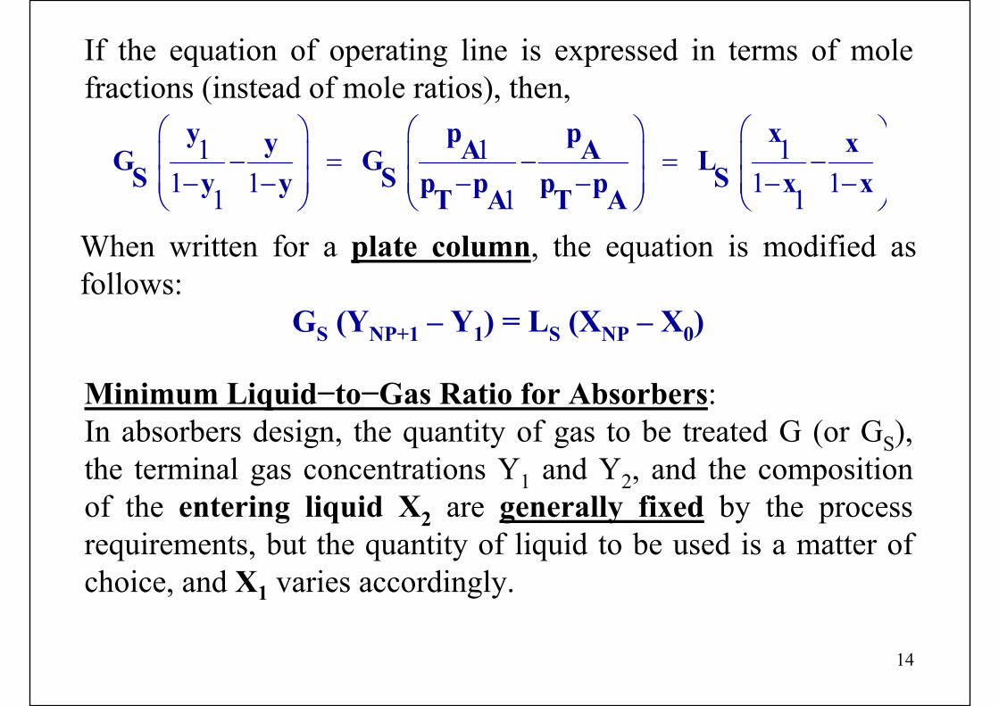
If the equation of operating line is expressed in terms of mole fractions (instead of mole ratios), then,
1 1 11 1 1 11 1 1
y p p xy xA AG G L S S Sy y p p p p x xT A T A
⎛ ⎞ ⎛ ⎞ ⎛ ⎞⎜ ⎟ ⎜ ⎟ ⎜ ⎟− = − = −⎜ ⎟ ⎜ ⎟ ⎜ ⎟− − − − − −⎝ ⎠ ⎝ ⎠ ⎝ ⎠
When written for a plate column, the equation is modified as follows:
GS (YNP+1 – Y1) = LS (XNP – X0)
Minimum Liquid−to−Gas Ratio for Absorbers:In absorbers design, the quantity of gas to be treated G (or GS), the terminal gas concentrations Y1 and Y2, and the composition of the entering liquid X2 are generally fixed by the process requirements, but the quantity of liquid to be used is a matter of choice, and X1 varies accordingly.

15
Minimum liquid−to−gas ratio for absorption
X2 X1 X1(max)
E F M
Y2
Y1
D
Slope = LS(min)/GS
P
Slope = LS/GS Operating line must pass through point D(X2,Y2), and must end at the ordinate Y1.If such a quantity of liquid is used to give line DE, the exit liquid will have composition X1.
16
If still lesser quantity of liquid is used, the exit liquid composition will be higher, say at point F, but absorption is more difficult. Hence the number of contacts between gas and liquid phase must be more, and the absorber must be talleraccordingly.The minimum liquid rate, which can be used for a given duty, is given by line DM that is tangent to the equilibrium curveat P. At P, the diffusion driving force is zero, the required contact time is infinite and this gives rise to an infinitely tallabsorption tower.
The above principles also apply to strippers, where an operating line touching anywhere the equilibrium curve represents a maximum ratio of liquid to gas and a maximum exit gas concentration.

17
Countercurrent Multistage Operation
(One component Transferred)
G1 GS y1 Y1
L0 LS x0 X0
GNP+1 GS yNP+1 YNP+1
Tray / Plate Absorber
1
2
3
NP−2
NP−1
NP
X1
X2
X3
XNP−2
XNP
Y1
Y2
Y3
Y4
YNP
XNP−1
YNP−2
YNP−1

18
The number of ideal stages required to bring about a given change in composition of the liquid or the gas, for either absorbers or strippers, can be determined graphically.
The nearer the operating line to the equilibrium curve, the more steps will be required and if the two curves touch at any point, it corresponds to (LS/GS)min ratio, and the number of steps will be infinite.
The construction for strippers is the same, except, that the operating line will be below the equilibrium curve.
19
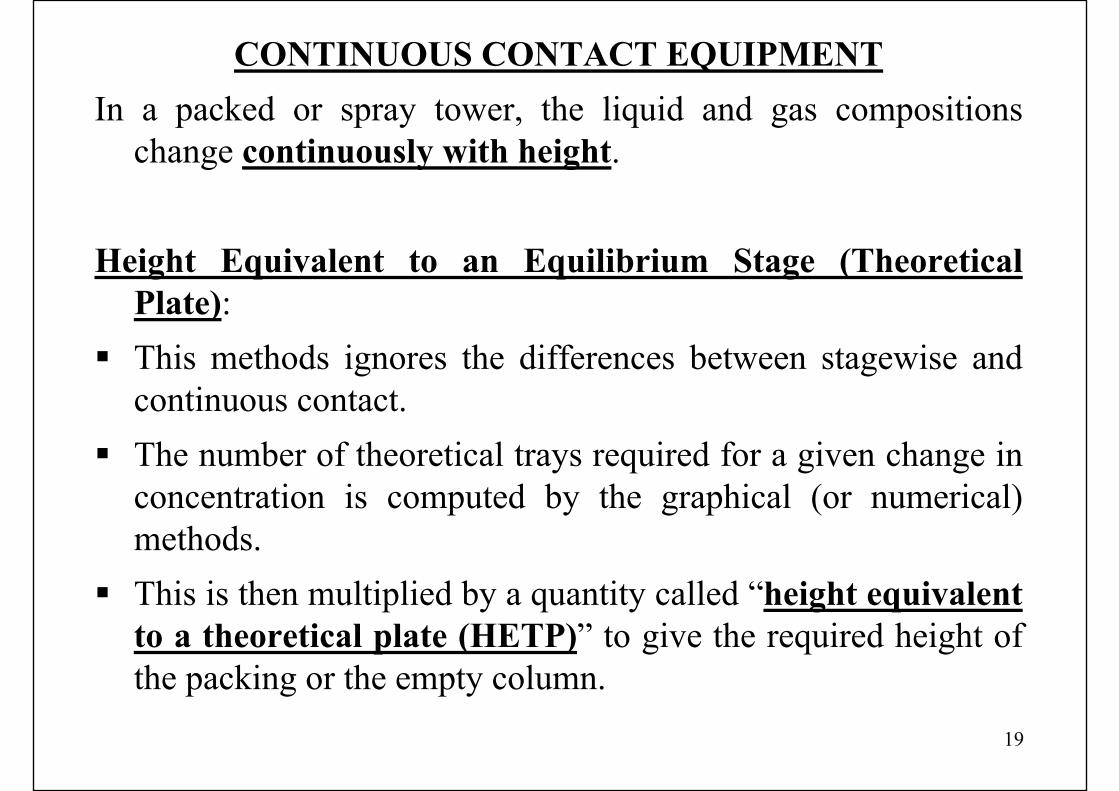
CONTINUOUS CONTACT EQUIPMENTIn a packed or spray tower, the liquid and gas compositions
change continuously with height.
Height Equivalent to an Equilibrium Stage (Theoretical Plate):This methods ignores the differences between stagewise and continuous contact.The number of theoretical trays required for a given change in concentration is computed by the graphical (or numerical) methods.This is then multiplied by a quantity called “height equivalent to a theoretical plate (HETP)” to give the required height of the packing or the empty column.
20
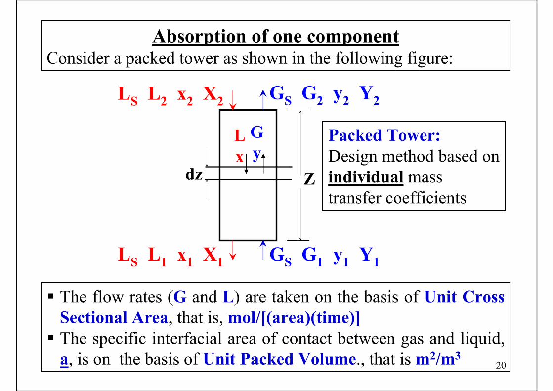
LS L2 x2 X2 GS G2 y2 Y2
Lx
Gy
dz
LS L1 x1 X1 GS G1 y1 Y1
Z
Packed Tower:Design method based on individual mass transfer coefficients
The flow rates (G and L) are taken on the basis of Unit Cross Sectional Area, that is, mol/[(area)(time)]The specific interfacial area of contact between gas and liquid,a, is on the basis of Unit Packed Volume., that is m2/m3
Absorption of one componentConsider a packed tower as shown in the following figure:
21
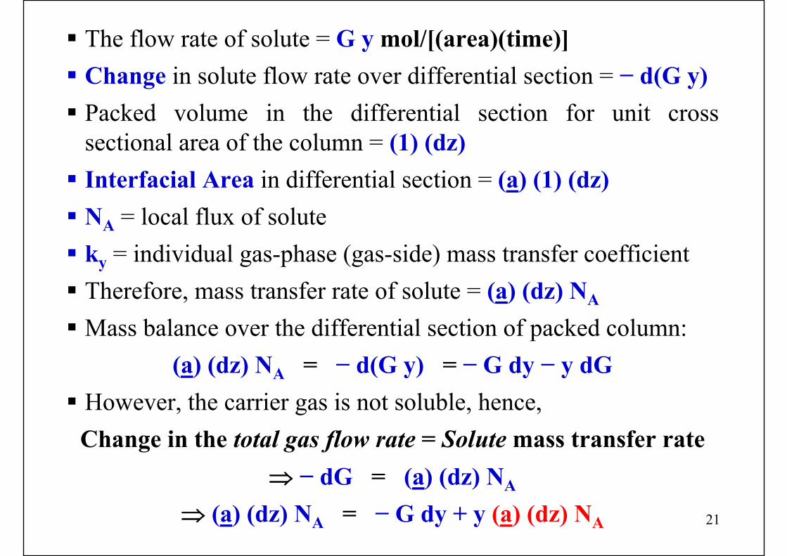
The flow rate of solute = G y mol/[(area)(time)]Change in solute flow rate over differential section = − d(G y)Packed volume in the differential section for unit cross sectional area of the column = (1) (dz)Interfacial Area in differential section = (a) (1) (dz)NA = local flux of soluteky = individual gas-phase (gas-side) mass transfer coefficientTherefore, mass transfer rate of solute = (a) (dz) NA
Mass balance over the differential section of packed column:(a) (dz) NA = − d(G y) = − G dy − y dG
However, the carrier gas is not soluble, hence,Change in the total gas flow rate = Solute mass transfer rate
⇒ − dG = (a) (dz) NA
⇒ (a) (dz) NA = − G dy + y (a) (dz) NA
22
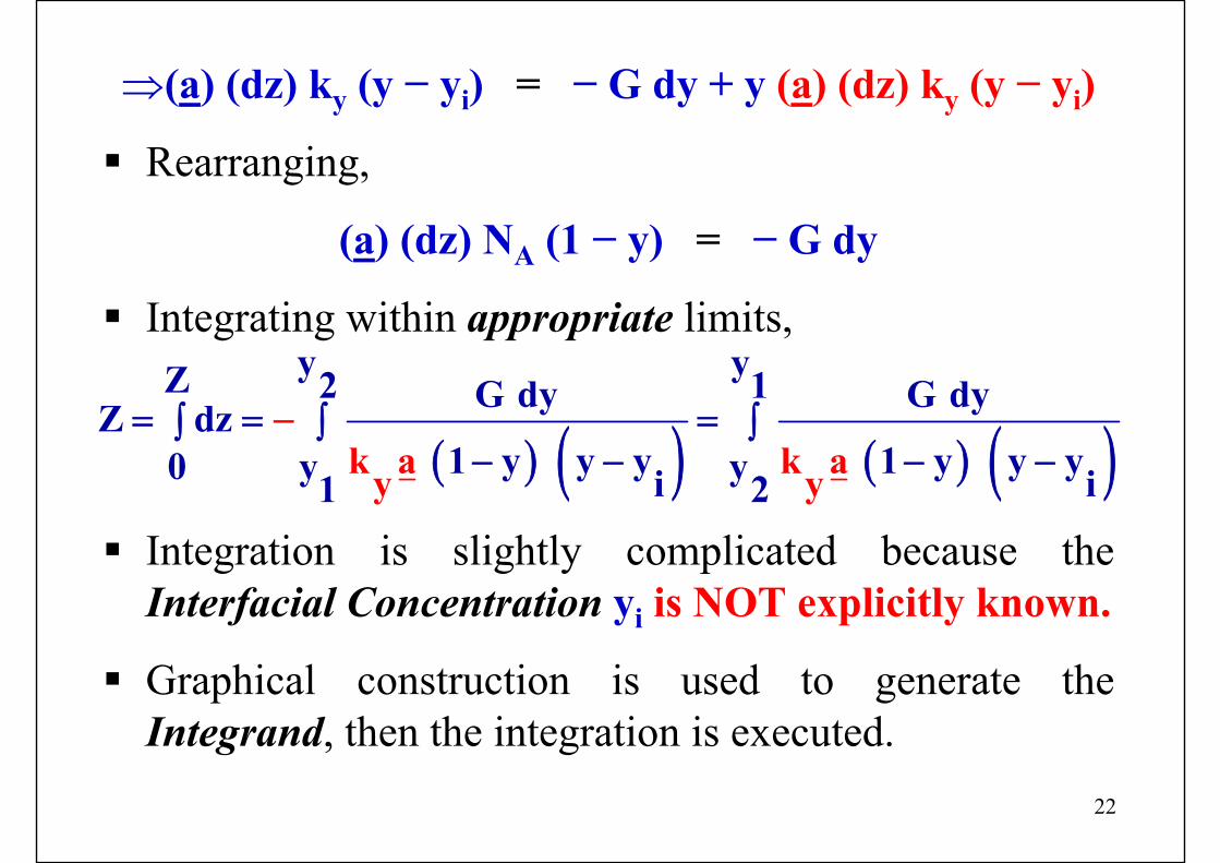
⇒(a) (dz) ky (y − yi) = − G dy + y (a) (dz) ky (y − yi)
Rearranging,
(a) (dz) NA (1 − y) = − G dy
Integrating within appropriate limits,
Integration is slightly complicated because the Interfacial Concentration yi is NOT explicitly known.
Graphical construction is used to generate the Integrand, then the integration is executed.
( ) ( ) ( ) ( )y yZ 2 1G dy G dyZ dz
1 y y y 1 y y y0 y yi i1k a k ay y2
−= = =∫ ∫ ∫− − − −
23
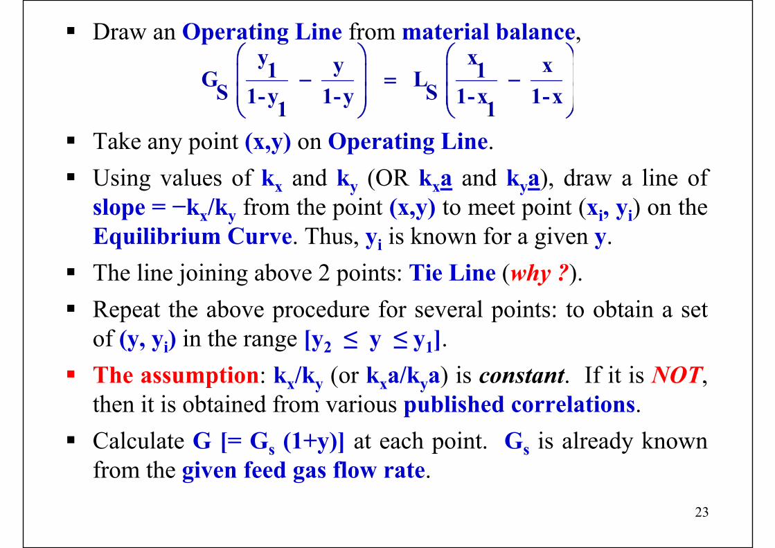
Draw an Operating Line from material balance,
Take any point (x,y) on Operating Line.Using values of kx and ky (OR kxa and kya), draw a line of slope = −kx/ky from the point (x,y) to meet point (xi, yi) on the Equilibrium Curve. Thus, yi is known for a given y.The line joining above 2 points: Tie Line (why ?).Repeat the above procedure for several points: to obtain a set of (y, yi) in the range [y2 ≤ y ≤ y1].The assumption: kx/ky (or kxa/kya) is constant. If it is NOT, then it is obtained from various published correlations.Calculate G [= Gs (1+y)] at each point. Gs is already known from the given feed gas flow rate.
y xy x1 1G L S S1-y 1-y 1-x 1-x1 1
⎛ ⎞ ⎛ ⎞⎜ ⎟ ⎜ ⎟− = −⎜ ⎟ ⎜ ⎟⎝ ⎠ ⎝ ⎠
24
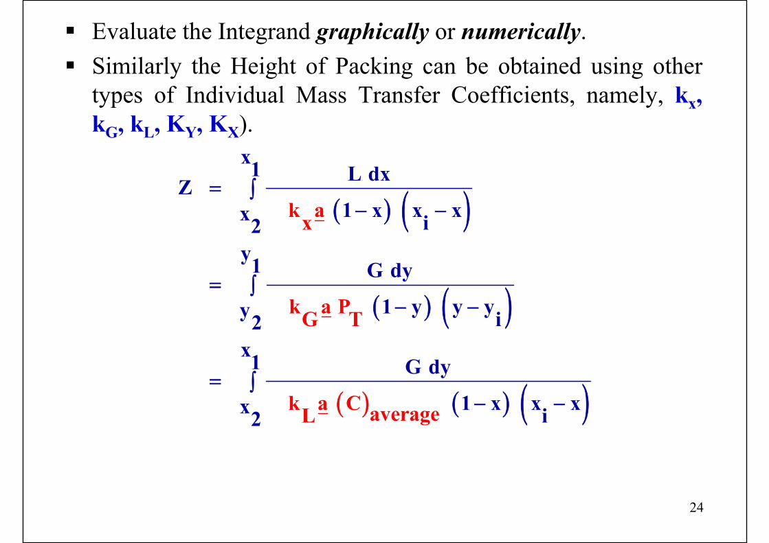
Evaluate the Integrand graphically or numerically.Similarly the Height of Packing can be obtained using other types of Individual Mass Transfer Coefficients, namely, kx, kG, kL, KY, KX).
( ) ( )
( ) ( )
( ) ( ) ( )
x1 L dxZ 1 x x xx i2
y1 G dy 1 y y yy i2
x1 G d
k ax
k a PG T
k a C avera
y 1 x x xx i2 geL
= ∫− −
= ∫− −
= ∫− −
25
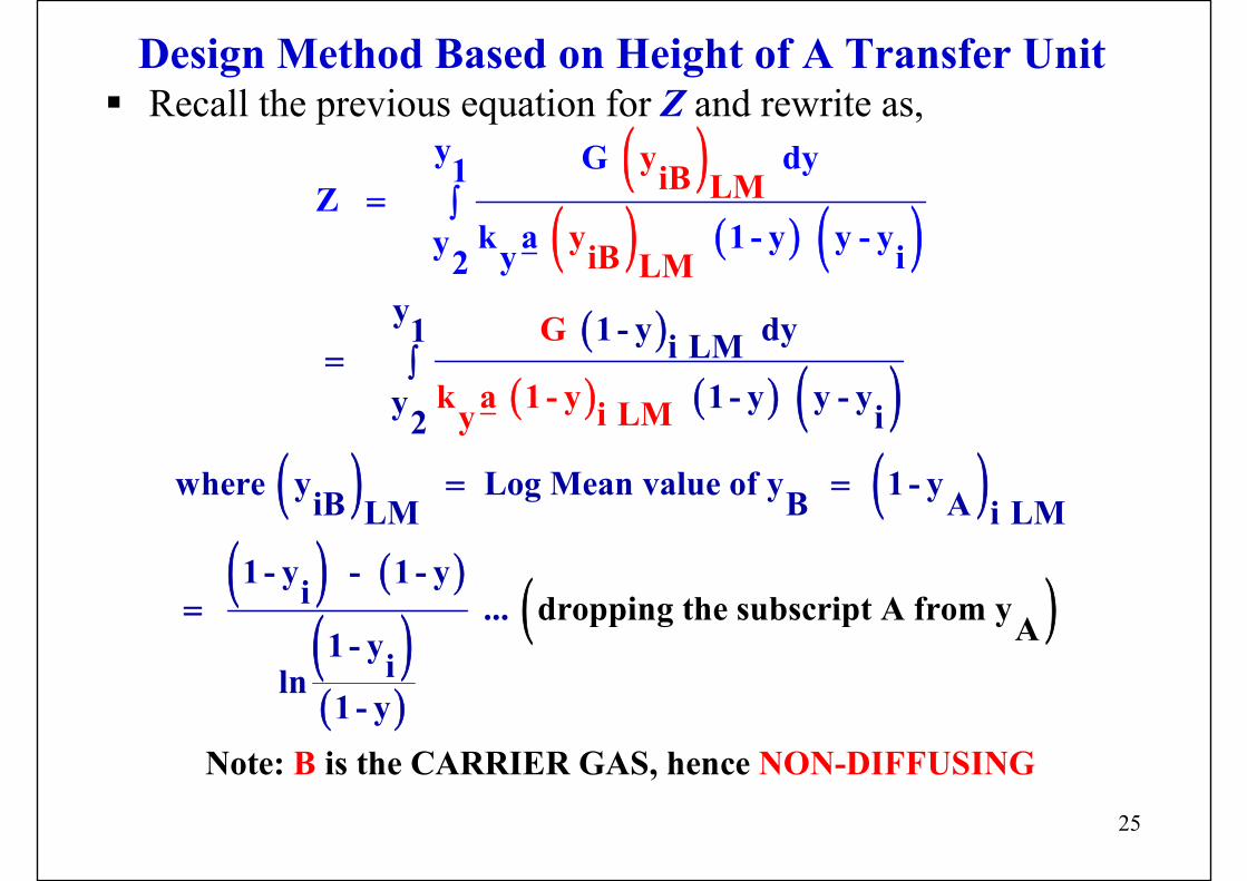
Design Method Based on Height of A Transfer UnitRecall the previous equation for Z and rewrite as,
( )( ) ( ) ( )( )
( ) ( ) ( )( ) ( )
( ) ( )
( )( )
( )
y 1 - y dy1 i LM 1 - y y - yy i2
where y Log Mean value of y 1 - yiB B ALM i LM
1 - y - 1 - yi
y G dy1Z
k a
... 1 - yiln1
yiB LMyiB LM
G
k a 1 - y i LM
dropping the subsc
- y
ript A from yA
Note: i
1 -
y
s th
y y2
B
- yy y i
= ∫
= =
=
= ∫
e CARRIER GAS, hen NON-DIFFUce SING
26
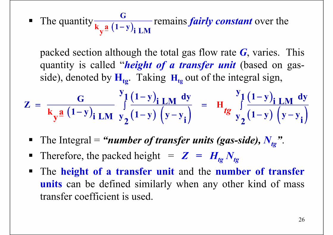
The quantity remains fairly constant over the
packed section although the total gas flow rate G, varies. This quantity is called “height of a transfer unit (based on gas-side), denoted by Htg. Taking Htg out of the integral sign,
The Integral = “number of transfer units (gas-side), Ntg”.Therefore, the packed height = Z = Htg Ntg
The height of a transfer unit and the number of transfer units can be defined similarly when any other kind of mass transfer coefficient is used.
( )G
1ay Mk y i L−
( )( )( ) ( )
( )( ) ( )
y y1 y dy 1 y dy1 1G i LM i LMZ H1 y 1 y y y 1 y y yy yi LM i i2
k ay 2
− −= =∫ ∫
− − − − −
tg
27
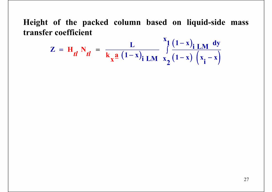
Height of the packed column based on liquid-side mass transfer coefficient
( )( )( ) ( )
tl tl
x 1 x dy1L i LMZ1 x 1 x x xxi LM i
H Nk ax 2
−= ∫
− − −=
28
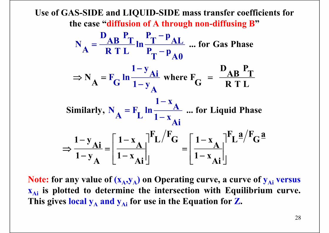
Use of GAS-SIDE and LIQUID-SIDE mass transfer coefficients for the case “diffusion of A through non-diffusing B”
... for Gas Phase
D PAB TN where F A G R T L
Similarly, ... for Liquid P
D P P pAB T T ALN lnA R T L P pT A
hase
F F F a F aL G L G1 y 1 x 1 xAi A A1 y 1 x 1
01 yAiF ln G 1 yA
1 xAN F lnA L 1 xA
xA Ai Ai
i
⇒ = =
⎡ ⎤ ⎡ ⎤− − −⎢ ⎥ ⎢ ⎥⇒ = =
− − −⎢ ⎥ ⎢ ⎥⎣ ⎦ ⎣ ⎦
−=
−
−
−
−=
−
Note: for any value of (xA,yA) on Operating curve, a curve of yAi versus xAi is plotted to determine the intersection with Equilibrium curve.This gives local yA and yAi for use in the Equation for Z.
29
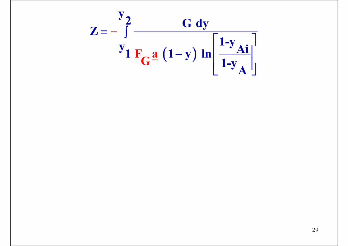
( )
y2 G dyZ1-yy Ai 1 y ln11-y
aGA
F
= ∫⎡ ⎤⎢ ⎥−⎢ ⎥⎣ ⎦
−
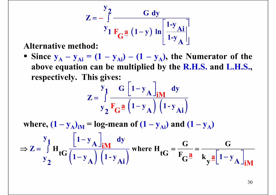
30
Alternative method:Since yA – yAi = (1 – yAi) – (1 – yA), the Numerator of the above equation can be multiplied by the R.H.S. and L.H.S., respectively. This gives:
( )
y2 G dyZ1-yy Ai 1 y ln11-y
aGA
F
= ∫⎡ ⎤⎢ ⎥−⎢ ⎥⎣ ⎦
−
( ) ( )iM
F a
y G 1 y dy1 AZ 1 y 1 - yy A Ai2 G
⎡ ⎤−⎣ ⎦= ∫
−
where, (1 – yA)iM = log-mean of (1 – yAi) and (1 – yA)
( ) ( )y 1 y dy1 G GH whereiM HAZ
a a 1 y1 y 1 - yy AAtG tG
Ai2 y iMF kG
⎡ ⎤−⎣ ⎦= ∫
⎡ ⎤−− ⎣
=
⎦
⇒ =
31
Numerical problems (HOME ASSIGNMENTS)(1)
In an experimental agitated contactor, pure CO2 is being absorbed in water at 25 0C and 2 atm.Water is pumped into the contactor @ 1 litre/minute and the carbonated water leaves the vessel continuously so that a constant volume is maintained in the contactor.The outlet water contains 2.3 gm CO2/litre.The specific interfacial area (a) of gas−liquid contact is 80 m2/m3 of the gas−liquid dispersion (volume of the gas−liquid dispersion is 8 litre). The liquid phase can be assumed to be well mixed.The solubility of CO2 in water can be calculated using Henry’s law.At 25 0C, the Henry’s law constant for CO2 is 1640 atm/mol fractionDiffusivity of CO2 in water is 1.92 × 10⁻⁹ m2/s.
Calculate the thickness of the liquid film if the film theory is applicable.
32
Numerical problems (HOME ASSIGNMENTS)(2)
The solute A is absorbed from a gas (G) in a liquid (L) in a countercurrent packed tower.Given:
Feed gas rate = 35 kmol/h, 10 mol% A, 90 mol% carrier;Liquid rate at the top (solute-free) = 40 kmol/hEquilibrium relation: Y = 1.1 X (Y is the concentration in the gas phase in the mole ratio unit).The overall driving force at the top (gas phase basis)
= (ΔY)TOP = 0.00555.What is the driving force at the bottom of the tower ?
33
Numerical problems (HOME ASSIGNMENTS)(3)
In a certain equipment used for the absorption of SO2 from air by water, at one section, the gas and liquid phase concentrations of the solute are 10 mol% and 4 mass% respectively.The solution density is 990.831 kg/m3.At the given temperature (40 0C) and pressure (10 atm), the distribution of SO2 between air and water can be approximately described by the equation: pA = 25 xA, where pA is the partial pressure of SO2 in the gas phase in atm.The individual mass transfer coefficients are:
kx = 10 kmol/[(h)(m2)(Δx)]ky = 8 kmol/[(h)(m2)(Δy)]
Calculate: (i) overall coefficient, KG in kmol/[(h)(m2)(Δp mmHg)](ii) xAi and yAi at the gas− liquid interface


![Gas Absorption[1]](https://img.pdfslide.us/doc/110x75/577c86ba1a28abe054c263df/gas-absorption1.jpg)