Embed Size (px)
Citation preview
Vučković, G., D.et. al.: Avoidable and Unavoidable Exergy Destruction and Exergoeconomic …
THERMAL SCIENCE, Year 2012, Vol. 16, Suppl. 2, pp. S493-S506 S493
AVOIDABLE AND UNAVOIDABLE EXERGY DESTRUCTION AND EXERGOECONOMIC EVALUATION OF THE THERMAL PROCESSES
IN A REAL INDUSTRIAL PLANT
by
Goran D. VU^KOVI]*, a, Mi}a V. VUKI]a, Mirko M. STOJILJKOVI]a, and Dragan D. VU^KOVI]b a
Faculty of Mechanical Engineering, University of Niš, Niš, Serbia
b
Faculty of Electronic Engineering, University of Niš, Niš, Serbia
Original scientific paper
DOI: 10.2298/TSCI
Exergy analysis is a universal method for evaluating the rational use of energy. It can be applied to any kind of energy conversion system or chemical process. An exergy analysis identifies the location, the magnitude and the causes of thermodynamic inefficiencies and enhances understanding of the energy conversion processes in complex systems. Conventional exergy analyses pinpoint components and processes with high irreversibility. To overcome the limitations of the conventional analyses and to increase our knowledge about a plant, advanced exergy-based analyses are developed. These analyses provide additional information about component interactions and reveal the real potential for improvement of each component constituting a system, as well as of the overall system. In this paper, a real industrial plant is analyzed using both conventional and advanced exergy analyses, and exergoeconomic evaluation. Some of the exergy destruction in the plant components is unavoidable and constrained by technological, physical and economic limitations. Calculations related to the total avoidable exergy destruction caused by each component of the plant supplement the outcome of the conventional exergy analysis. Based on the all-reaching analysis, by improving the boiler operation (elimination of approximately 1 MW of avoidable exergy destruction in the steam boiler) the greatest improvement in the efficiency of the overall system can be achieved.
Key words: exergy, exergy destruction, conventional exergetic analysis, advanced exergy analysis, exergoeconomic
Introduction and background
Exergy analysis is a mighty tool for development, assessment and improvement of all existing energy systems. A conventional exergy analysis denotes components and processes into the energy systems that are highly unrecoverable [1]. For complex energy systems, with large number of components, exergy destruction of a certain component
* Corresponding author; [email protected]
Vučković, G., D.et. al.: Avoidable and Unavoidable Exergy Destruction and Exergoeconomic …
S494 THERMAL SCIENCE, Year 2012, Vol. 16, Suppl. 2, pp. S493-S506.
depends on its own characteristics, but also on other components inefficiencies. The conventional exergy analysis displays certain limitations which are considerably decreased in an advanced or detailed exergy analysis [2]. In this point of view, the advanced exergy analysis performs the splitting total exergy destruction into the parts. In the one division, total exergy destruction can be splitting into the part which can be avoided, therefore called ''avoidable'', and into the part which can not be avoided, named ''unavoidable''. In the other division exergy destruction can be splitting into the endogenous and exogenous exergy destruction which are not going to be dealt with in this paper. An advanced exergy analysis has the purpose to supply engineers with more useful information related to energy systems improvement potential.
In their paper [3] Tsatsaronis and Park split exergy destruction into avoidable and unavoidable parts and demonstrate the advantages of dividing exergy destruction and economic costs into avoidable and unavoidable parts on the example of cogenerative plants. In the paper [4] Morosuk and Tsataronis introduced how to calculate the parts of exergy destruction in an advanced exergy analysis. Application of this approach to a simple gas-turbine system reveals the potential for improvement and the interactions among the system components. The same authors in the paper [5] presented a detailed exergy analysis of a novel co-generation concept that combined LNG regasification with the generation of power.
The first idea of combining thermodynamics and costs originated from Lotka in 1921 [6]. In 1932, Keenan suggested using the second law of thermodynamics regarding the costs [7]. Even though the work was not about exergy costs, exergy (at that point “availability”) has been used to separate costs of electricity and steam produced in cogeneration plants. Keenan showed that the ''availability'' is more convenient property to base evaluation of electricity and steam than energy.
Tribus and Evans was firstly expressed the interest for formulating connections between the efficiency and costs [8]. They suggested an idea about the costs of exergy and its uses in engineering economy, introducing the term “Thermoeconomics” in 1956 [9]. The essence of Evans-Tribus approach lies in the management of money, fuel costs, work costs and amortized capital costs related to plants by connecting the usefulness of each step with its exergy. El-Sayed and Evans published in 1970 a crucial paper [10], which proposes the mathematical explanation/foundation for the optimization of heat systems. Many years later, Frangopoulos, in 1983, and Von Spasovsky, in 1986, applied and formalized Evans and El-Sayed’s optimization method, in their Ph.D. theses.
One of the basic sources in exergy analysis and thermoeconomics is a book [11] published in 1985 by Kotas. In 1984, in his paper [12] Tsatsaronis introduced for the first time the term exergoeconomics as a more precise word for the concept of thermoeconomics on account of which he directly pointed at the thermodynamic value – exergy which is combined with economic principals. Since the expression thermoeconomics was used in such general terms expressing the interaction between any thermodynamic value and economy, Tsatsaronis proposed that all those methods for calculating the costs based on exergy should be known as exergoeconomics. In [13], Tsatsaronis and Winhold introduced a “Fuel-Product”, concept, which later became the base to define the exergy efficiency, one of the most important criterions for evaluating components of energy systems. Rosen [14] claimed that the existing understanding and developed tools related to exergy and economics connection have been significant success. He also pointed out the need for further development and simplifications in order to apply this theory in practical situations. Rivero et al. [15] investigated exergy
Vučković, G., D.et. al.: Avoidable and Unavoidable Exergy Destruction and Exergoeconomic …
THERMAL SCIENCE, Year 2012, Vol. 16, Suppl. 2, pp. S493-S506 S495
improvement potential of components in the crude oil refinery, as a measure of how much and how easily the system could be improved for optimization purposes. In the chapter [16] Valero and Torres introduced the malfunction concept, as a represents the increase of irreversibility in a device suffering an inefficiency or efficiency degradation.
Methodology
Energy and conventional exergy analysis
Since the engineering analyses, energy systems are very often idealized as being at steady state, meaning that all the properties are not changed in time. For a control volume at steady state, the identity of the matter within the control volume changes continuously, but the total amount of mass remains constant [17]. The control volume energy balance rate at the steady state for the k-th component, without kinetic and potential energy, is [18]:
cv cv0 k k k ki ei e
Q W m h m h (1)
The conventional exergy analysis, presented in this paper, can be classified as exergy flow method or exergy balance method [19, 20]. According to this method the control volume exergy balance rate at the steady state for the k-th component of the energy system can be expressed as [18]:
, , cv , , D,0 q k j k i k e kj i e
E W E E E (2)
Fuel-Product Concept and Splitting Exergy Destruction
Definitions of exergy efficiency and exergoeconomic analysis rely on the so-called concept of ''Fuel-Product'' [13]. The product is defined in accordance with the aim of purchase and the use of the component. The term fuel stands for the primary energy, raw materials, semi-products and others, which is needed for making product. In exergy analysis the fuel and the product are expressed by means of exergy dimensions. The value of exergy destruction for tne overall energy system, can be calculated using the ''Fuel-Product'' concept from the exergy balance for the total energy system:
F,tot P,tot L,tot D,totE E E E (3)
Using the same concept for component level, exergy balans can be expressed as:
F, P, L, D,k k k kE E E E (4)
The loss of exergy is characterized as irreversibility as a result of the interaction between the system and the surrounding environment. These irreversibility values may be determined by the transfer of matter in the surroundings or by transferring the heat energy or work in the surrounding. Often the exergy loss presents a small part of thermodynamic inefficiencies, while the most part generates unrecoverable values within the system. If the boundaries of a system or a component are set where the temperature is equal to the referent
Vučković, G., D.et. al.: Avoidable and Unavoidable Exergy Destruction and Exergoeconomic …
S496 THERMAL SCIENCE, Year 2012, Vol. 16, Suppl. 2, pp. S493-S506.
environment temperature, all the thermodynamic inefficiencies are assigned to the exergy destruction, while the exergy loss is equal to zero, ĖL,k=0.
The industrial plants or complex energy systems are built to produce one or more finished products. On the other hand, the resource identified by means of electrical and/or energy flows becomes the fuel for the whole energy system. Therefore, all components in the energy system have its fuel and products, but the whole system also has its fuel (the resource) and its products (finished products).
The total exergy destruction calculated from the exergy balance of the component can be splitting into an avoidable and unavoidable part [21, 4]:
AV UND, D, D,k k kE E E (5)
The unavoidable part of exergy destruction of the component presents a part which cannot be eliminated, even if the best available technologies are used. In order to determine the unavoidable part of exergy destruction in a system component, it is required to consider each component separately from the others, as if it was removed from the system [22]. At the same time, the premise is that the component works in unavoidable conditions - with high efficiency and minimal losses [1]. Under these conditions, the specific unavoidable exergy destruction is defined as the ratio between the exergy destruction of the component and the exergy of its product (ĖD,k / ĖP,k)
UN. The specific unavoidable exergy destruction should be multiplied with the exergy of product of the component in real operating conditions [23]:
UN
D,UND, P,
P,
kk k
k
EE E
E
(6)
The calculated value using the equitation (6) represent a part of exergy destruction of the component which cannot be avoided in the observed energy system. When calculating the unavoidable part of exergy destruction, the decision maker has to introduce certain presumptions related mainly to the work conditions of the components, that are, to some extent, arbitrary and rely on the subjective comprehention and predictions related to the future enhancements.
The avoidable part of exergy destruction represents the difference between the total exergy destruction of the component and the part which cannot be avoided (5). Thus, the avoidable part of exergy destruction is the objective potential for improving the efficiency of the component in an energy system.
Real and unavoidable operation conditions and exergy efficiency
Making a distinction between the avoidable and unavoidable part of exergy destruction is possible only after defining the total value of exergy destruction for the component under considerations. Calculating the total value of exergy destruction is the first step in the conventional exergy analysis or in observes the energy system in realistic conditions. The real operation conditions include real in-going data and actual thermodynamic efficiency for all components in energy system under considerations. Using the data obtained from the conventional exergy analysis application, one cannot get insight into improvement potential of the entire energy system or certain components. Moreover, contributions of other components are not recognized.
Vučković, G., D.et. al.: Avoidable and Unavoidable Exergy Destruction and Exergoeconomic …
THERMAL SCIENCE, Year 2012, Vol. 16, Suppl. 2, pp. S493-S506 S497
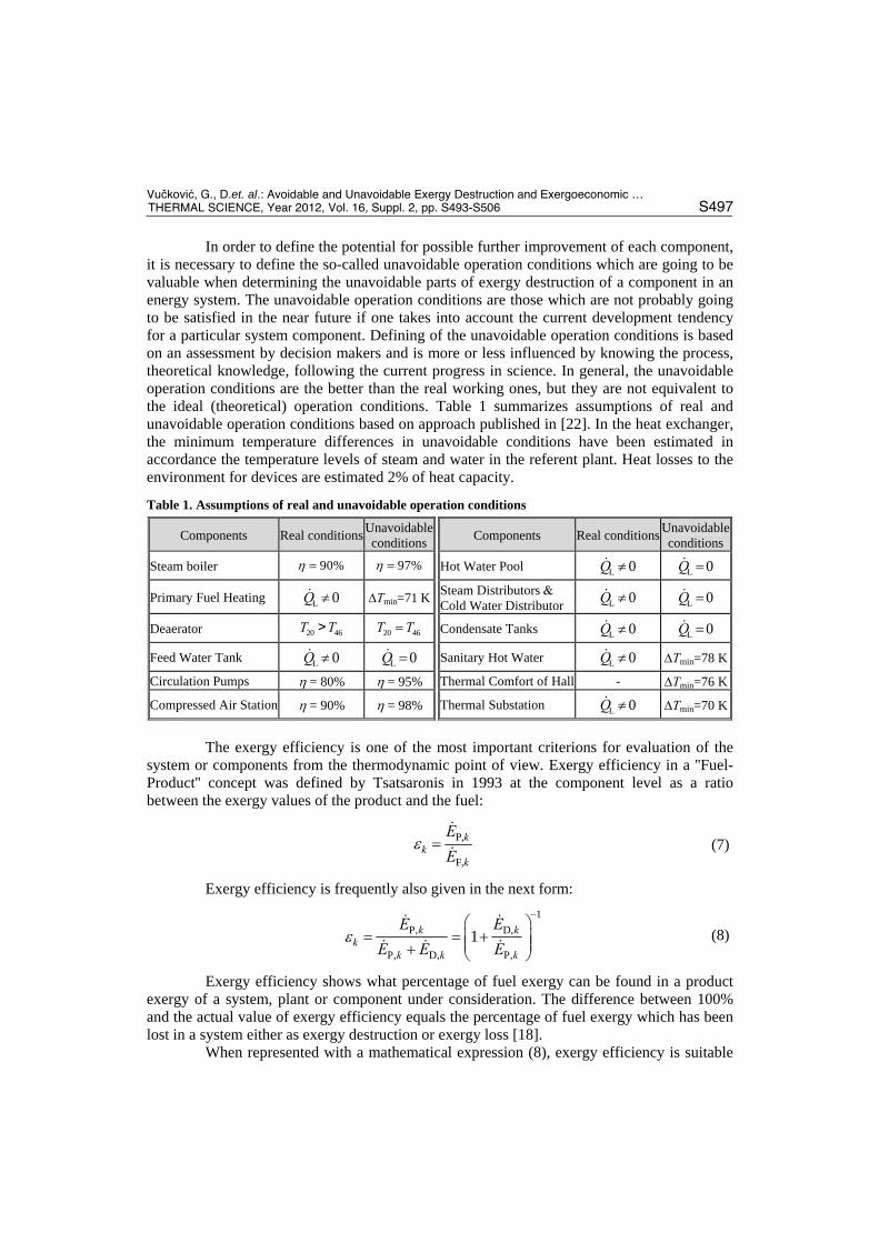
In order to define the potential for possible further improvement of each component, it is necessary to define the so-called unavoidable operation conditions which are going to be valuable when determining the unavoidable parts of exergy destruction of a component in an energy system. The unavoidable operation conditions are those which are not probably going to be satisfied in the near future if one takes into account the current development tendency for a particular system component. Defining of the unavoidable operation conditions is based on an assessment by decision makers and is more or less influenced by knowing the process, theoretical knowledge, following the current progress in science. In general, the unavoidable operation conditions are the better than the real working ones, but they are not equivalent to the ideal (theoretical) operation conditions. Table 1 summarizes assumptions of real and unavoidable operation conditions based on approach published in [22]. In the heat exchanger, the minimum temperature differences in unavoidable conditions have been estimated in accordance the temperature levels of steam and water in the referent plant. Heat losses to the environment for devices are estimated 2% of heat capacity.
Table 1. Assumptions of real and unavoidable operation conditions
Components Real conditions Unavoidable conditions
xbb
Components Real conditions Unavoidable conditions
Steam boiler 90% 97% Hot Water Pool L 0Q L 0Q
Primary Fuel Heating L 0Q Tmin=71 KSteam Distributors Cold Water Distributor L 0Q L 0Q
Deaerator 20 46T T> 20 46T T Condensate Tanks L 0Q L 0Q
Feed Water Tank L 0Q L 0Q Sanitary Hot Water L 0Q Tmin=78 K
Circulation Pumps = 80% = 95% Thermal Comfort of Hall - Tmin=76 K
Compressed Air Station = 90% = 98% Thermal Substation L 0Q Tmin=70 K
The exergy efficiency is one of the most important criterions for evaluation of the
system or components from the thermodynamic point of view. Exergy efficiency in a ''Fuel-Product'' concept was defined by Tsatsaronis in 1993 at the component level as a ratio between the exergy values of the product and the fuel:
P,
F,
kk
k
E
E
(7)
Exergy efficiency is frequently also given in the next form:
1
P, D,
P, D, P,
1k kk
k k k
E E
E E E
(8)
Exergy efficiency shows what percentage of fuel exergy can be found in a product exergy of a system, plant or component under consideration. The difference between 100% and the actual value of exergy efficiency equals the percentage of fuel exergy which has been lost in a system either as exergy destruction or exergy loss [18].
When represented with a mathematical expression (8), exergy efficiency is suitable
Vučković, G., D.et. al.: Avoidable and Unavoidable Exergy Destruction and Exergoeconomic …
S498 THERMAL SCIENCE, Year 2012, Vol. 16, Suppl. 2, pp. S493-S506.
for determining the maximum exergy efficiency in a component [23]:
1UN
D,max
P,
1 kk
k
E
E
(9)
The component will have maximum exergy efficiency when it works with minimum exergy destruction or with minimal value of specific unavoidable exergy destruction (9).
A useful variable for comparison of dissimilar components is the exergy destruction ratio, defined at the component level as:
D,
D,F,tot
kk
Ey
E
(10)
The exergy destruction ratio is a measure of the contribution of the exergy destruction within the k-th component to the reduction of the overall exergy efficiency [1].
Exergoeconomic analysis
Exergoeconomic costs basically stand for the monetary costs of stream of matter and energy flows. The functions of exergoeconomic costs for: incoming and outgoing stream of matter, exergy connected with the work transfer and exergy related to the heat transfer may be represented as products of average exergoeconomic costs per unit of exergy and a suitable value of exergy and work in the following forms [18], respectively: i i i i i iC c E c m e ,
e e e e e eC c E c m e , w wC c W , and 01q q q q sC c E c Q T T .
In the ''Fuel- Product'' concept, for an energy system in a steady state, the cost of finished products equals the sum of the resource costs, costs regarding capital investment, operation and maintenance, and it can be presented in the following mathematical expression:
CI OMP,tot F,tot tot tot F,tot totC C Z Z C Z (11)
Equation (11) represents exergoeconomic balances of the overall energy system. The same form of equation (11) is valid for the component level, also.
Defining exergoeconomic costs implies determining exergoeconomic balance for every component individually within a system. Exergoeconomic balance for every component shows that the sum of exergoeconomic cost rates associated with all exiting exergy streams equals the sum of exergoeconomic cost rates of all entering exergy streams plus a value of costs regarding capital investment and operating and maintenance. For a component receiving a heat transfer and generating power, the exergoeconomic balance can be expressed as [18]:
, , , ,e k w k q k i k ke i
C C C C Z (12)
If it is a case of those components which exploit energy (such as compressors or pumps), the second term of equation (12) moves to the right side. Furthermore, the first term on the right side of equation (12) moves to the left side in the case of a heat emitting
Vučković, G., D.et. al.: Avoidable and Unavoidable Exergy Destruction and Exergoeconomic …
THERMAL SCIENCE, Year 2012, Vol. 16, Suppl. 2, pp. S493-S506 S499
component. In general, exergoeconomic balance is always given with the terms being positive. By using mathematical expressions for, Ċi, Ċe, Ċw, Ċq, equation (12) becomes:
, , ,e e w k k q k q k i i kk ke i
c E c W c E c E Z (13)
The values for the exergy in stream of metter and energy flows are estimated by exergy analysis. The value of non-exergy costs is calculated from the levelized costs regarding capital investment, operation and maintenance on a yearly basis and is given with a time unit (year, hour or a second). In case of determining exergy costs for each of m flows within one energy system, it is necessary to write m independent equations. If one or more components have any outgoing flows that are not qualified as the loss flows, or a branching there of, additional equations for each component have to be added. The number of added equations is equal to the number of outgoing flows minus one.
The relative cost difference for the energy system components is defined as:
P, F,
F,
k kk
k
c cr
c
(14)
This variable stands for the relative increase in costs per exergy unit between the fuel and product of the component in question. The relative increase in costs is very useful when both calculating and optimizing the system component.
Process description
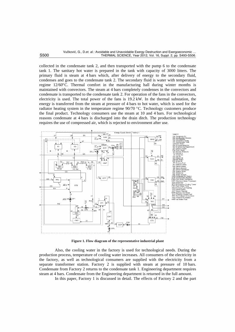
The energy system in a representative factory, fig. 1, consists of four parts: Energy supply sector (EN), Factory 1 (F1), Factory 2 (F2) and Engineering Department (ED).
Energy supply sector is a part of the factory complex where chemical and thermal treatment of water is carried out, and superheated steam for their own use and supply of all other consumers is produced. Also, in this section, compressed air and cooling water for the whole factory complex are prepared. The boiler produces superheated steam at the pressure of 10 bars, which is then distributed to factories 1 and 2, and partly reduced at lower pressures in accordance with the needs of consumers. In this paper, it is assumed that the fuel used is heavy oil. Compressed air at pressure of 7 bars is prepared in the compressed air station where electricity is used to drive the compressors. Consumers of compressed air are Factory 1, Factory 2 and Engineering department. Cooling water for both factories is prepared in the evaporative cooling tower. A spray jet of cooling water, transported from the pool of hot water, spreads over the tube bundle of evaporative heat exchanger and collects into the reservoir. Forced air flow is provided with the centrifugal ventilator, while water drops removal within the air flow is prevented with the droplet eliminator. The cooled water transported with pump 4 to consumers in factories 1 and 2, and compressed air station.
Factory 1 is the largest consumer of energy in the whole complex and is supplied with energy using the superheated steam at the pressure of 10 bars, compressed air and cooling water. Electric energy is provided from a separate transformer station. The processes that consume the most of the energy supplied to the factory are: preparation of sanitary hot water, heating of manufacturing plants, thermal substation and technological consumers. Consumers in the factory use the steam at pressures of 10 and 4 bars. The condensate is
Vučković, G., D.et. al.: Avoidable and Unavoidable Exergy Destruction and Exergoeconomic …
S500 THERMAL SCIENCE, Year 2012, Vol. 16, Suppl. 2, pp. S493-S506.
collected in the condensate tank 2, and then transported with the pump 6 to the condensate tank 1. The sanitary hot water is prepared in the tank with capacity of 3000 litters. The primary fluid is steam at 4 bars which, after delivery of energy to the secondary fluid, condenses and goes to the condensate tank 2. The secondary fluid is water with temperature regime 12/60C. Thermal comfort in the manufacturing hall during winter months is maintained with convectors. The steam at 4 bars completely condenses in the convectors and condensate is transported to the condensate tank 2. For operation of the fans in the convectors, electricity is used. The total power of the fans is 19.2 kW. In the thermal substation, the energy is transferred from the steam at pressure of 4 bars to hot water, which is used for the radiator heating system in the temperature regime 90/70 C. Technology customers produce the final product. Technology consumers use the steam at 10 and 4 bars. For technological reasons condensate at 4 bars is discharged into the drain ditch. The production technology requires the use of compressed air, which is rejected to environment after use.
Figure 1. Flow diagram of the representative industrial plant
Also, the cooling water in the factory is used for technological needs. During the production process, temperature of cooling water increases. All consumers of the electricity in the factory, as well as technological consumers are supplied with the electricity from a separate transformer station. Factory 2 is supplied with steam at pressure of 10 bars. Condensate from Factory 2 returns to the condensate tank 1. Engineering department requires steam at 4 bars. Condensate from the Engineering department is returned in the full amount.
In this paper, Factory 1 is discussed in detail. The effects of Factory 2 and the part
Vučković, G., D.et. al.: Avoidable and Unavoidable Exergy Destruction and Exergoeconomic …
THERMAL SCIENCE, Year 2012, Vol. 16, Suppl. 2, pp. S493-S506 S501
that deals with Engineering department are considered on the basis of real values of superheated steam that they use. The representative system of the considered rubber factory was mathematically modeled with 30 components and 72 streams.
Results and discussion
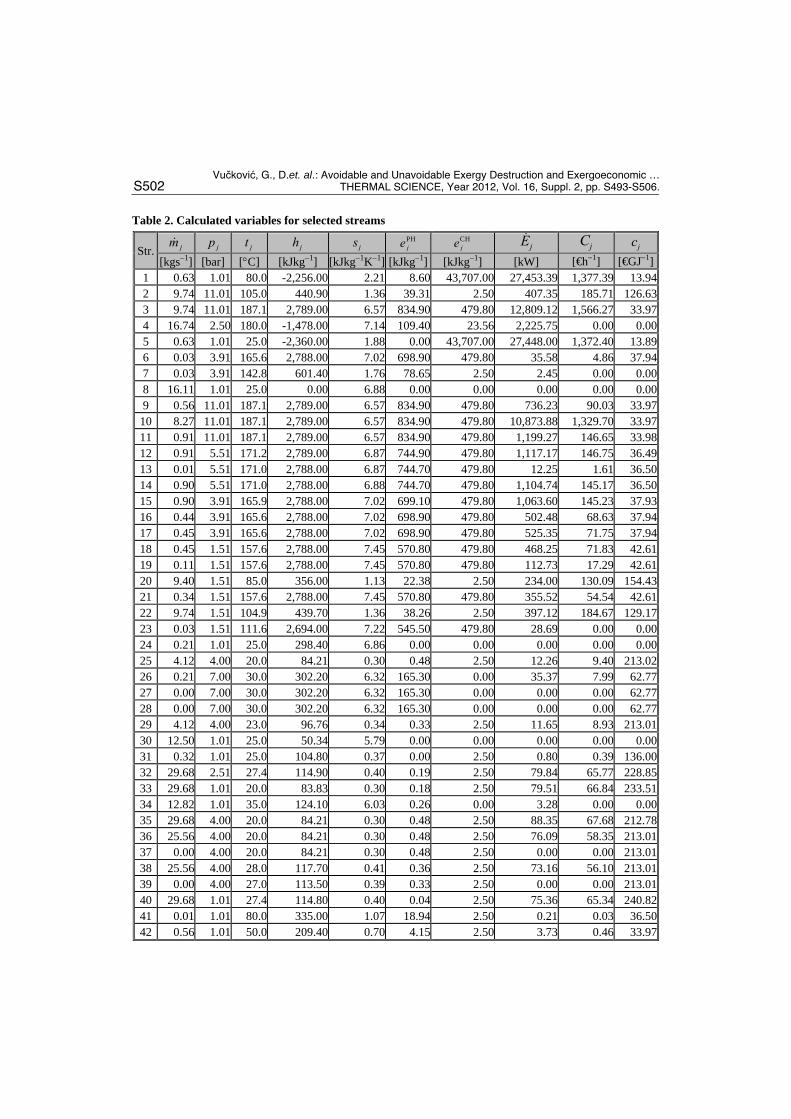
Each segment of the system shown in fig. 1 was separately analyzed and for each component mass, energy and exergy balances were defined. The results of the thermodynamic and exergoeconomic analysis for selected steams are presented in tab. 2. Input data for the calculation were pressures and temperatures in different points of the flows of streams obtained from the existing process of the referent plant. Official data on lower heating values for the fuel were used. The cost of air provided was considered to be zero. The highest values of the cost rate Ci, were reached in the representative industrial plant in streams that had high physical and/or chemical exergy.
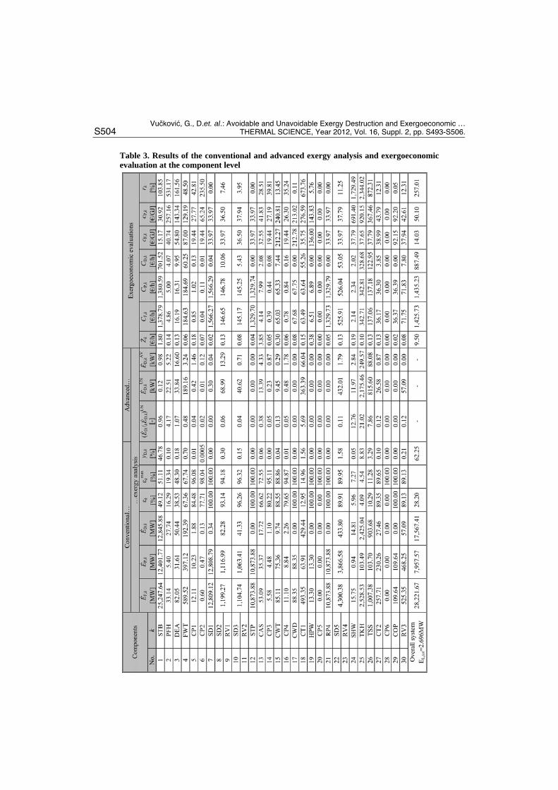
For solving the defined mathematical model, a specialized software package called Engineering Equation Solver [24] was used. The results of the conventional and advanced exergetic analysis and exergoeconomic analysis at the component level are presented in tab. 3. The rate kZ for the steam boiler, circulation pumps and compressed air station was calculated include the estimated investment cost for implementing energy efficiency measures and real annual operating and maintenance cost, and for the other components by dividing the real annual operating and maintenance cost with the 4000 hours of system operation per year.
Having in mind that the reduce valves typically serve other elements, the reduce valve and the component it serve should be considered together [18]. In the manner of conventional exergy analysis, exergy of fuel and product, exergy destruction, exergy efficiency and exergy destruction ratio for selected components are presented in this paper. Values of unavoidable and avoidable exergy destruction are also presented for selected components in the advanced exergy analysis in this paper. Values of operation and maintenance cost, exergoeconomc cost and relative cost difference for selected components are presented in exergoeconomic evaluation.
Values for cooling tower were not calculated, because thay have no meaningful effect on the product, and thus no meaningful exergy efficiency, for a heat exchanger that allows heat transfer across the temperature of environment [18]. The impact of technological consumers on the other system components is taken through the flow rate values of process fluids, which correspond to the real plant depending on the amount of finished products.
The exergy efficiency of a total plant indicates that some potential exists for the improvement of the overall efficiency and reduction of costs. Exergy losses are mainly associated with the exhaust gases as well as the exergy transfer to the environment. From the total exergy losses, the loss of exhaust gas is 82.54% or 2,225.75 kW. All exergy losses account together for 9.82% or 2,696.69 kW of the fuel exergy supplied to the overall plant. More than 48% of the fuel exergy is destroyed within the plant components. The exergy destruction ratio provides information about the performance of each component and enables the comparison of dissimilar components. Values for exergy destruction ratio indicate that the boiler has most impact on reducing exergy efficiency of the overall system.
The steam boiler has a big potential for increasing the efficiency, forasmuch it having the highest value of exergy destruction ratio (46.78%), but very low value for exergy efficiency (49.12%).
Vučković, G., D.et. al.: Avoidable and Unavoidable Exergy Destruction and Exergoeconomic …
S502 THERMAL SCIENCE, Year 2012, Vol. 16, Suppl. 2, pp. S493-S506.
Table 2. Calculated variables for selected streams
Str. jm jp jt jh js PHje CH
je jE jC jc
[kgs1] [bar] [C] [kJkg1] [kJkg1K1] [kJkg1] [kJkg1] [kW] [€h1] [€GJ1] 1 0.63 1.01 80.0 -2,256.00 2.21 8.60 43,707.00 27,453.39 1,377.39 13.942 9.74 11.01 105.0 440.90 1.36 39.31 2.50 407.35 185.71 126.633 9.74 11.01 187.1 2,789.00 6.57 834.90 479.80 12,809.12 1,566.27 33.974 16.74 2.50 180.0 -1,478.00 7.14 109.40 23.56 2,225.75 0.00 0.005 0.63 1.01 25.0 -2,360.00 1.88 0.00 43,707.00 27,448.00 1,372.40 13.896 0.03 3.91 165.6 2,788.00 7.02 698.90 479.80 35.58 4.86 37.947 0.03 3.91 142.8 601.40 1.76 78.65 2.50 2.45 0.00 0.008 16.11 1.01 25.0 0.00 6.88 0.00 0.00 0.00 0.00 0.009 0.56 11.01 187.1 2,789.00 6.57 834.90 479.80 736.23 90.03 33.97
10 8.27 11.01 187.1 2,789.00 6.57 834.90 479.80 10,873.88 1,329.70 33.9711 0.91 11.01 187.1 2,789.00 6.57 834.90 479.80 1,199.27 146.65 33.9812 0.91 5.51 171.2 2,789.00 6.87 744.90 479.80 1,117.17 146.75 36.4913 0.01 5.51 171.0 2,788.00 6.87 744.70 479.80 12.25 1.61 36.5014 0.90 5.51 171.0 2,788.00 6.88 744.70 479.80 1,104.74 145.17 36.5015 0.90 3.91 165.9 2,788.00 7.02 699.10 479.80 1,063.60 145.23 37.9316 0.44 3.91 165.6 2,788.00 7.02 698.90 479.80 502.48 68.63 37.9417 0.45 3.91 165.6 2,788.00 7.02 698.90 479.80 525.35 71.75 37.9418 0.45 1.51 157.6 2,788.00 7.45 570.80 479.80 468.25 71.83 42.6119 0.11 1.51 157.6 2,788.00 7.45 570.80 479.80 112.73 17.29 42.6120 9.40 1.51 85.0 356.00 1.13 22.38 2.50 234.00 130.09 154.4321 0.34 1.51 157.6 2,788.00 7.45 570.80 479.80 355.52 54.54 42.6122 9.74 1.51 104.9 439.70 1.36 38.26 2.50 397.12 184.67 129.1723 0.03 1.51 111.6 2,694.00 7.22 545.50 479.80 28.69 0.00 0.0024 0.21 1.01 25.0 298.40 6.86 0.00 0.00 0.00 0.00 0.0025 4.12 4.00 20.0 84.21 0.30 0.48 2.50 12.26 9.40 213.0226 0.21 7.00 30.0 302.20 6.32 165.30 0.00 35.37 7.99 62.7727 0.00 7.00 30.0 302.20 6.32 165.30 0.00 0.00 0.00 62.7728 0.00 7.00 30.0 302.20 6.32 165.30 0.00 0.00 0.00 62.7729 4.12 4.00 23.0 96.76 0.34 0.33 2.50 11.65 8.93 213.0130 12.50 1.01 25.0 50.34 5.79 0.00 0.00 0.00 0.00 0.0031 0.32 1.01 25.0 104.80 0.37 0.00 2.50 0.80 0.39 136.0032 29.68 2.51 27.4 114.90 0.40 0.19 2.50 79.84 65.77 228.8533 29.68 1.01 20.0 83.83 0.30 0.18 2.50 79.51 66.84 233.5134 12.82 1.01 35.0 124.10 6.03 0.26 0.00 3.28 0.00 0.0035 29.68 4.00 20.0 84.21 0.30 0.48 2.50 88.35 67.68 212.7836 25.56 4.00 20.0 84.21 0.30 0.48 2.50 76.09 58.35 213.0137 0.00 4.00 20.0 84.21 0.30 0.48 2.50 0.00 0.00 213.0138 25.56 4.00 28.0 117.70 0.41 0.36 2.50 73.16 56.10 213.0139 0.00 4.00 27.0 113.50 0.39 0.33 2.50 0.00 0.00 213.0140 29.68 1.01 27.4 114.80 0.40 0.04 2.50 75.36 65.34 240.8241 0.01 1.01 80.0 335.00 1.07 18.94 2.50 0.21 0.03 36.5042 0.56 1.01 50.0 209.40 0.70 4.15 2.50 3.73 0.46 33.97
Vučković, G., D.et. al.: Avoidable and Unavoidable Exergy Destruction and Exergoeconomic …
THERMAL SCIENCE, Year 2012, Vol. 16, Suppl. 2, pp. S493-S506 S503
Table 2. (Continued) Calculated variables for selected streams
Str. jm jp jt jh js PHje CH
je jE jC jc
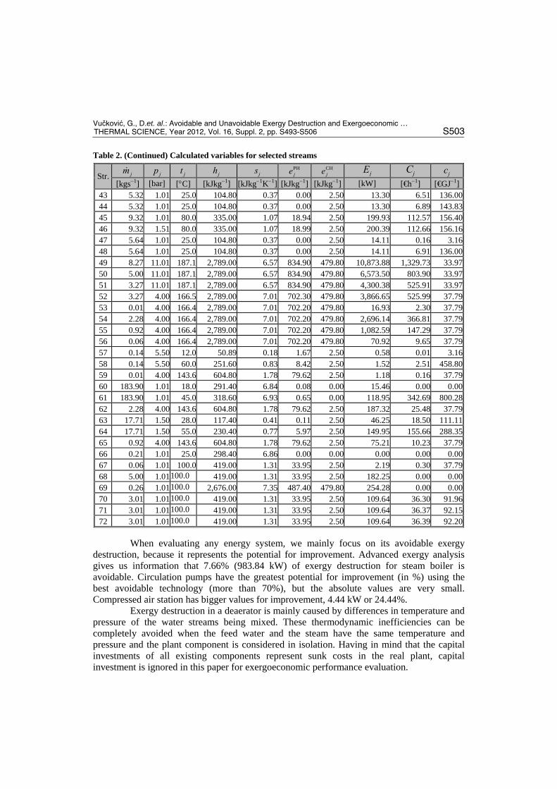
[kgs1] [bar] [C] [kJkg1] [kJkg1K1] [kJkg1] [kJkg1] [kW] [€h1] [€GJ1] 43 5.32 1.01 25.0 104.80 0.37 0.00 2.50 13.30 6.51 136.0044 5.32 1.01 25.0 104.80 0.37 0.00 2.50 13.30 6.89 143.8345 9.32 1.01 80.0 335.00 1.07 18.94 2.50 199.93 112.57 156.4046 9.32 1.51 80.0 335.00 1.07 18.99 2.50 200.39 112.66 156.1647 5.64 1.01 25.0 104.80 0.37 0.00 2.50 14.11 0.16 3.1648 5.64 1.01 25.0 104.80 0.37 0.00 2.50 14.11 6.91 136.0049 8.27 11.01 187.1 2,789.00 6.57 834.90 479.80 10,873.88 1,329.73 33.9750 5.00 11.01 187.1 2,789.00 6.57 834.90 479.80 6,573.50 803.90 33.9751 3.27 11.01 187.1 2,789.00 6.57 834.90 479.80 4,300.38 525.91 33.9752 3.27 4.00 166.5 2,789.00 7.01 702.30 479.80 3,866.65 525.99 37.7953 0.01 4.00 166.4 2,789.00 7.01 702.20 479.80 16.93 2.30 37.7954 2.28 4.00 166.4 2,789.00 7.01 702.20 479.80 2,696.14 366.81 37.7955 0.92 4.00 166.4 2,789.00 7.01 702.20 479.80 1,082.59 147.29 37.7956 0.06 4.00 166.4 2,789.00 7.01 702.20 479.80 70.92 9.65 37.7957 0.14 5.50 12.0 50.89 0.18 1.67 2.50 0.58 0.01 3.1658 0.14 5.50 60.0 251.60 0.83 8.42 2.50 1.52 2.51 458.8059 0.01 4.00 143.6 604.80 1.78 79.62 2.50 1.18 0.16 37.7960 183.90 1.01 18.0 291.40 6.84 0.08 0.00 15.46 0.00 0.0061 183.90 1.01 45.0 318.60 6.93 0.65 0.00 118.95 342.69 800.2862 2.28 4.00 143.6 604.80 1.78 79.62 2.50 187.32 25.48 37.7963 17.71 1.50 28.0 117.40 0.41 0.11 2.50 46.25 18.50 111.1164 17.71 1.50 55.0 230.40 0.77 5.97 2.50 149.95 155.66 288.3565 0.92 4.00 143.6 604.80 1.78 79.62 2.50 75.21 10.23 37.7966 0.21 1.01 25.0 298.40 6.86 0.00 0.00 0.00 0.00 0.0067 0.06 1.01 100.0 419.00 1.31 33.95 2.50 2.19 0.30 37.7968 5.00 1.01100.0 419.00 1.31 33.95 2.50 182.25 0.00 0.0069 0.26 1.01100.0 2,676.00 7.35 487.40 479.80 254.28 0.00 0.0070 3.01 1.01100.0 419.00 1.31 33.95 2.50 109.64 36.30 91.9671 3.01 1.01100.0 419.00 1.31 33.95 2.50 109.64 36.37 92.1572 3.01 1.01100.0 419.00 1.31 33.95 2.50 109.64 36.39 92.20
When evaluating any energy system, we mainly focus on its avoidable exergy
destruction, because it represents the potential for improvement. Advanced exergy analysis gives us information that 7.66% (983.84 kW) of exergy destruction for steam boiler is avoidable. Circulation pumps have the greatest potential for improvement (in %) using the best avoidable technology (more than 70%), but the absolute values are very small. Compressed air station has bigger values for improvement, 4.44 kW or 24.44%.
Exergy destruction in a deaerator is mainly caused by differences in temperature and pressure of the water streams being mixed. These thermodynamic inefficiencies can be completely avoided when the feed water and the steam have the same temperature and pressure and the plant component is considered in isolation. Having in mind that the capital investments of all existing components represent sunk costs in the real plant, capital investment is ignored in this paper for exergoeconomic performance evaluation.
Vučković, G., D.et. al.: Avoidable and Unavoidable Exergy Destruction and Exergoeconomic …
S504 THERMAL SCIENCE, Year 2012, Vol. 16, Suppl. 2, pp. S493-S506.
Table 3. Results of the conventional and advanced exergy analysis and exergoeconomic evaluation at the component level
Vučković, G., D.et. al.: Avoidable and Unavoidable Exergy Destruction and Exergoeconomic …
THERMAL SCIENCE, Year 2012, Vol. 16, Suppl. 2, pp. S493-S506 S505
Plant components with a large value of the sum ,k D kZ C should be improved first (STB, TSS, TCH). Components TCH, SHW, TSS, CT1 and PFH have the biggest relative increase in the average cost per exergy unit between fuel and product.
Components such as CT1, SHW, TKH and TSS have very high values of the relative cost difference, but it is noticeable that their values of exergy of fuel and exergy destruction are many times greater than the exergy of product. Therefore, the general suggestion is to reduce the exergy of flows 16, 53, 54 and 55 with the aim of increasing the efficiency of the overall system and reducing the consumption of heavy oil.
Conclusions
The results of the conventional exergy analysis are strongly supplemented by the advanced exergy analysis. Irreversibilities identified in the conventional exergy analysis are split, according to their origins, in the advanced exergy analysis. Only the part of the irreversibilities that can be avoided should be considered for the improvement of a plant with interacting processes.
In this paper, an industrial plant was analyzed using both conventional and advanced exergy analysis, and exergeconomic performance evaluation. The highest exergy destruction is caused by the steam boiler. More than 97% of the total exergy destruction of the overall system comes from the boiler. Moreover 92.34% of the total exergy destruction in steam boiler cannot be avoided. Similar to the results of the conventional analysis, the advanced analysis ranks the improvement priority of the steam boiler first, followed by the thermal comfort of the hall and the thermal substation.
The splitting exergy destruction into endogenous and exogenous parts, combined splitting, and consideration the increase in pressure and temperature of the generated steam, in order to have a cogeneration plant, increasing the factory performances we are investigation in the next step in this study.
Nomenclature
Ċ – exergoeconomic cost rate [€s1]Ė – exergy flow rate [kW]
Q – heat transfer rate [kW] T – temperature [K] W – work rate [kW] Z – non-exergy cost rate [€s1] c – cost per unit of exergy [€J1] e – specific exergy [kJkg1] h – specific entalphy [kJkg1] m – mass flow rate [kgs1] r – relative cost difference [-] s – specific entrophy [kJkg1K1] t – temperature [C] yD – exergy destruction ratio
Greek symbols
– difference – exergy efficiency – thermal efficiency
Subscripts
D – destructionF – fuelL – lossP – productcv – control volumee – outlet stream j – stream of matterk – system componentmin – minimalq – heat transfertot – overall systemw – work
Superscripts
AV – avoidable CH – chemical max – maximal PH – physical UN – unavoidable
Vučković, G., D.et. al.: Avoidable and Unavoidable Exergy Destruction and Exergoeconomic …
S506 THERMAL SCIENCE, Year 2012, Vol. 16, Suppl. 2, pp. S493-S506.
References
[1] Petrakopoulou, F., et al., Conventional and Advanced Exergetic Analyses Applied to a Combined Cycle Power Plant, Article in press, Energy, doi:10.1016/j.energy.2011.05.028, (2011).
[2] Kelly, S., Tsatsaronis, G., Morosuk, T., Advanced Exergetic Analysis: Approaches for Splitting the Exergy Destruction into Endogenous and Exogenous Parts, Energy, 34 (2009), pp. 384-391.
[3] Tsatsaronis, G., Park, H., On Avoidable and Unavoidable Exergy Destructions and Investment Costs in Thermal Systems, Energy Conversion and Management, 43 (2002), pp. 1259-1270.
[4] Morosuk, T., Tsatsaronis, G., Advanced Exergy Analysis for Chemically Reacting Systems-Application to a Simple Open Gas-Turbine System, Int. J. of Thermodynamics, 12 (2009), 3, pp. 105-111.
[5] Tsatsaronis, G., Morosuk, T., Advanced Exergetic Analysis of a Novel System for Generating Electricity and Vaporizing Liquefied Natural Gas, Energy, 35 (2010), pp. 820-829.
[6] Sciubba, E., Wall, G., A Brief Commented History of Exergy from the Beginnings to 2004, International Journal of Thermodynamics, 10 (2007), pp. 1-26.
[7] Keenan, J. H, A Steam Chart for Second law analysis, Mechanical engineering, 54 (1932), pp. 195-204. [8] Abusoglu, A., Kaganlu, M., Exergoeconomic Analysis and Optimization of Combined Heat and Power
Production: A Review, Renewable & Sustainable Energy Reviews, 13 (2009), pp. 2295-2308. [9] Tribus, M., et al: Thermodynamic and Economic Considerations in the Preparation of Fresh Water from
Sea Water, First Draft, ULCA Report No. 56-16, University of California, Los Angeles, USA, 1956. [10] El-Sayed, M. Y., Evans, R. B., Thermoeconomics and the Design of Heat Systems, Journal of
Engineering for Power, 92 (1970), 1, pp. 27-35. [11] Kotas, T. J., The Exergy Method of Thermal Plant Analysis, Butterworths, London, UK, 1985. [12] Tsatsaronis, G., Combination of Exergetic and Economic Analysis in Energy-Conversion Processes, in:
Energy Economics and Management in Industry, Proceedings (Pergamon Press, Oxford, England), European Congress, Algarve, Portugal, 1984, Vol. 1, pp. 151-157.
[13] Tsatsaronis, G., Winhold, M., Exergoeconomic Analysis and Optimization of Energy Conversion Plants. Part I: A New General Methodology; Part II: Analysis of a Coal – Fired Steam Power Plant, Energy, 10 (1985), 1, pp. 69-94.
[14] Rosen, A. M., Exergy and Economics: Is Exergy Profitable?, Exergy, 2 (2002), pp. 218–220. [15] Rivero, R., Garcia, M., Urquiza, J., Simulation, Exergy Analysis and Application of Diabatic Distillation
to Tertiary Amyl Methyl Ether Production Unit of a Crude Oil Refinery, Energy, 29 (2004), pp. 467-489. [16] Valero, A., Cuadra, T. C., Application of Thermoeconomic to Operation Diagnosis of Energy Plants, in
Exergy, Energy System Analysis and Optimization, Vol. 2 (Ed. C. A. Frangopoulos), EOLSS, Oxford, 2009, pp. 146-161.
[17] Moran, M., Shapiro, H., Fundamentals of Engineering Thermodynamics, Wiley & Sons Inc., 2006. [18] Bejan, A., Tsatsaronis, G., Moran, M., Thermal Design and Optimization, Wiley & Sons Inc., 1996. [19] Szargut, J., Morris, D., Steward, F., Exergy Analysis of Thermal, Chemical, and Metallurgical
Processes, Hemisphere Publishing Corporation, 1988. [20] Wall, G., Exergetics, Mölndal, Sweden, 2009. [21] Morosuk, T., Tsatsaronis, G., How to Calculate the Parts of Exergy Destruction in an Advanced
Exegetic Analysis, Proceedings, 21st ECOS Conference, Cracow, Poland, 2008, Vol. 1, pp. 185-194. [22] Cziesla, F., Tsatsaronis, G., Gao, Z., Avoidable Thermodynamic Inefficiencies and Costs in an
Externally Fired Combined Cycle Power Plant, Energy, 31 (2006), pp. 1472-1489. [23] Kelly, S., Energy Systems Improvement based on Endogenous and Exogenous Exergy Destruction,
Ph.D. Thesis, Technischen Universität Berlin, Berlin, Germany, 2008. [24] ***, Engineering Equation Solver, http://www.fchart.com
Paper submitted: May 3, 2012.
Paper revised: September 14, 2012.
Paper accepted: September 20, 2012.