Embed Size (px)
Citation preview
Pergamon
www.elsevier.com/locatelpnucene
Progress in Nuclear Energy, Vol. 42, No. 1, pp. M-106, 2003
Available online at www.sciencedirect.com Published by Elsevier Science Ltd
d
Printed in Great Britain .C,.“C. DIII.CT* 0149s1970/03/$ - see front matter
PII: SO149-1970(02)00098-7
Analytical Benchmark Test Set For Criticality
Code Verification
Avneet Sood, R. Arthur Forster, and D. Kent Parsons
Los Ahmos National Laboratory, Applied Physics (X) Division, X-5 Diagnostics Applications Group, P. 0. Box 1663, MS F663, Los Alarmos, NM 87545
Abstract
A number of published numerical solutions to analytic eigenvalue (k,ff) and eigen- function equations are summarized for the purpose of creating a criticality verifi-
cation benchmark test set. The 75-problem test set allows the user to verify the
correctness of a criticality code for infinite medium and simple geometries in one-,
two-, three-, and six-energy groups, with one-, two-, and four-media. The problems
include both isotropic and linearly and quadratically anisotropic neutron scattering.
The problem specifications will produce both k,ff=l and the quoted k, to at least
five decimal places. MCNP (Briesmeister, 1997) and DANTSYS (Alcouff, R.E, et al., 1995) have been verified using these problems. Additional uses of the test set
for code verification are also discussed. Published by Elsevier Science Ltd.
Key words: analytic; benchmark; criticality; code verification
1 Introduction
This paper describes a set of benchmark problems with analytic eigenvalue (k,ff) and eigenfunction (flux) solutions to the neutron transport equation from peer-reviewed journal articles. The purpose of the test set is to verify that transport algorithms and codes can correctly calculate the analytic k,f, and fluxes. The authors believe the reported eigenvalues and eigenfunctions to
be accurate to at least five decimal places even though many references often report higher precision values. The higher precision eigenvalues and eigen- functions from the references are reproduced here. These test set problems for infinite medium, slab, cylindrical, and spherical geometries in one- and
Email addresses: asoodQlan1. gov (Avneet Sood), raf Qlanl . gov (R. Arthur Forster), dkpQlan1. gov (D. Kent Parsons).
55
56 A. Sood et al.
Nature Experiment
Measured l
Diagnostics c-
Radiation 4 Transport Code Validation Experimental Theory Model
I * 7
Mathematical Code Verification Code and Data Computational. t -
Model Simulation
t Analytic Solutions, 3 Verification Data
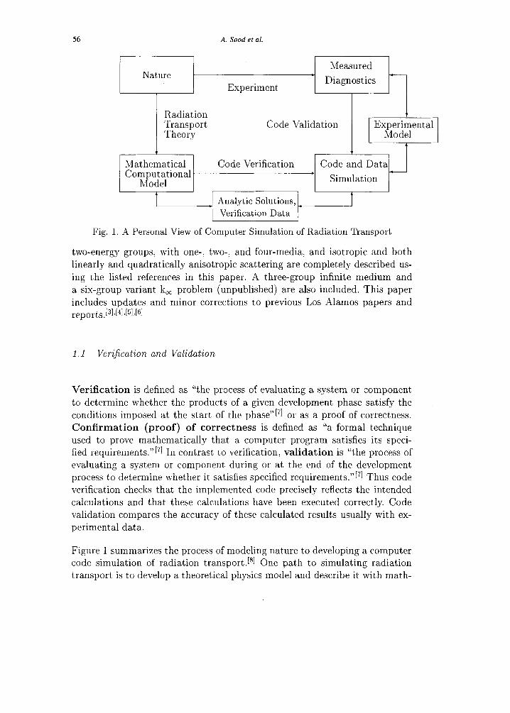
Fig. 1. A Personal View of Computer Simulation of Radiation Transport
two-energy groups, with one-, two-; and four-media, and isotropic and both linearly and quadratically anisotropic scattering are completely described us-
ing the listed references in this paper. A three-group infinite medium and a six-group variant k, problem (unpublished) are also included. This paper
includes updates and minor corrections to previous Los Alamos papers and reports.I31~[41,[51,[61
1.1 Veri:fcation and Validation
Verification is defined as “the process of evaluating a system or component
to determine whether the products of a given development phase satisfy the conditions imposed at the start of the phase”L71 or as a proof of correctness. Confirmation (proof) of correctness is defined as “a formal technique
used to prove mathematically that a computer program satisfies its speci- fied requirements. “PI In contrast to verification, validation is “the process of evaluating a system or component during or at the end of the development process to determine whether it satisfies specified requirements.“[71 Thus code verification checks that the implemented code precisely reflects the intended calculations and that these calculations have been executed correctly. Code validation compares the accuracy of these calculated results usually with ex-
perimental data.
Figure 1 summarizes the process of modeling nature to developing a computer code simulation of radiation transport. [*I One path to simulating radiation transport is to develop a theoretical physics model and describe it with math-
Criticality code verification 57
ematical equations. Exact solutions to these complex theoretical equations are often impossible. Solutions to the mathematical equations require simplifying
assumptions and are approximated with a carefully developed computer code. Code verification is the link between these mathematical and computational equations and the computer simulation. Verification of the code and data sim- ulation includes comparisons of calculated results with analytic solutions and simplified verification data intended to be used only to verify computer code
numerical performance. Other forms of code verification include comparisons
with an accepted standard set of code output for regression testing, results from other computer codes, and line-by-line debugging.
A second path to characterizing radiation transport is to perform careful ex- periments and measure physical quantities using diagnostics. The accuracy of the measured diagnostics is limited by approximations and assumptions in the experimental methods and by the precision of the diagnostic equipment. Care-
fully designed experiments often infer or directly measure a desired physical parameter from the theoretical models and equations and thus are measure-
ments of its true value. Code validation is the link between the measured diagnostics and the computer code with the general purpose physical data required by the computer simulation. Code and data validation includes com-
parison of the calculated code output with results from experiments and from other computer codes.
Figure 1 shows the process of developing a computer code simulation requires code verification, validation, and physical data. Importantly, the figure shows there is no direct path linking nature and computer simulation. Code verifi- cation must be performed before code validation. The objectives of this paper
are to define and document a set of analytic eigenvalue and eigenfunction
benchmarks for verifying criticality codes. Benchmark is defined as “a stan- dard against which measurement or comparisons can be made.“171 Available
benchmarks for code verification do not focus on criticality problems.[gl Vali- dation benchmarks from crit’ical experiments do exist, but are not verification
benchmarks.[rOl 4 n initial effort to compile a benchmark test set for critical- ity calculation verification was begun, but not completed.[1’l~[121 The analytic
benchmarks described here can be used to verify computed numerical solutions
for k,ff and the associated flux with virtually no uncertainty in the numerical benchmark values.
1.2 Why These Solutions Serve as a Test Set
All critical dimensions, k,,,, and scalar neutron flux results quoted here are based on numerical computations using the analytic solutions to the k,,, eigen- value (homogeneous) transport equation for “simple” problems. The analytic

58 A. Sood et al.
methods used include Case’s singular eigenfunction[13], F,v and SN methods, [141~[151 and Green’s functions.[‘6]
All of these test set problem specifications and results are from peer-reviewed .journals, and have, in some cases, been solved numerically using more than one
analytic solution. All calculated values for critical dimensions, k,,,, and the
scalar neutron flux are believed to be accurate to at least five decimal places. Several critical dimensions and scalar neutron flux are reported to more than
five decimal places. The higher precision eigenvalues and eigenfunctions from
the references are simply reproduced here.
1.3 Scope of the Criticality Verijkation Test Set
The verification test set was chosen to represent a LLwide” range of problems from the relatively small number of published solutions. These problems in-
clude simple geometries, few neutron energy groups, and simplified (isotropic and linearly anisotropic) scattering models. The problems use neutron cross sections that are reasonable representations of the materials described. These
cross sections are not general purpose multi-group values. The cross sections are used because they are extracted from the literature results and are in-
tended to be used only to verify algorithm performance and not to predict.
criticality experiments.
The basic geometries include an infinite medium,, slab, cylinder, and sphere with one- and two-energy group representations of uniform homogeneous ma-
terials. The slab and cylinder geometries are one-dimensional, as shown in Figure 2; that is, each is finite in one dimension (thickness for slab and radius for the cylinders) and infinite elsewhere. The two-media problems surround
each geometry with a specified thickness of reflector. Solutions for one-, two-, and three-group infinite medium problems are derived in appendix A.
The emphasis of the test set is on the fundamental eigenvalue, k,,,. All
k eff eigenvalues for finite fissile materials are unity to at least five decimal
places. The k, values for a uniform homogeneous infinite medium are greater than unity. Few numerical eigenfunction solutions are published; consequently, mainly one-group and uniform homogeneous infinite medium fluxes are in- cluded in the test set results.
The critical dimension, rcr is defined pictorially for the one-dimensional, one- medium problem geometries in Figure 2, as well as the two-media infinite slab lattice cell. Reflector dimension(s) are provided for the reflected cases.

Criticality code verification 59
rc -I ::
i r
; :
noderator Fuel
rc
Moderslor
Fig. 2. Critical Dimension, rc, for Bare One-Dimensional Geometries and Infinite
Slab Lattice Cell
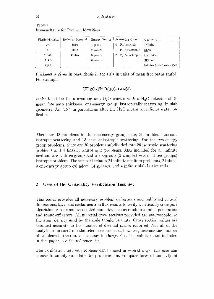
To assist in verification, each problem has a unique identifier. Since the test set
includes bare and multi-media problems, there are two forms of the identifier.
The first form is for a bare geometry:
Fissile Material - Energy Groups - Scattering - Geometry
The possible entries for each category are listed in Table 1. The fissile materials and identifier consist of Pu-239 (PU), U-235 (U), highly enriched uranium- aluminum-water assembly (UAL), low enrichment uranium and D20 reactor
system (UD20), and a highly enriched uranium research reactor (URR). The identifier may be followed by a letter to differentiate between different cross
section sets from nominally the same material. The table lists identifiers for the reflector material (if any), number of energy groups, scattering order, and geometry. The geometry is identified by the first two letters in the table. The exception is for the infinite slab lattice cell which uses ISLC. An example of the one material form of the identifier is:
u-2-o-SP
which is the identifier for a bare U-235 reactor isotropically scattering, in spherical geometry.
(no reflector), 2 energy groups,
The second form of the identifier includes the reflecting material. The reflectors
are usually Hz0 with an exception of a three region Fe, Pb, Fe reflector. Al- though many of the reflectors are identified as HZO, the reflector cross sections are unique to each problem. Consequently, a letter may follow H20 indicating the Hz0 cross section set used. The multi-media identifier form is:
Fissile Material - Reflecting Material (thickness) - Energy Groups - Scattering - Geometry
To separate multiple reflector thicknesses for the same fissile material, the
60 A. Sood et al.
Table 1 Nomenclature for Problem Identifiers
Fissile Material Reflector Material Energy Groups Scattering Order Geometry
PC bare 1 group 0 - PO Isotropic INfinite
U HZ0 2 groups 1 PI Anisotropic &ab
UD20 Fe-Na 3 groups 2 Pz Anisotropic Glindcr
UAL 6 groups xhere
URR infinite Slab Lattice Cell
thickness is given in parenthesis in t’he title in units of mean free paths (mfp).
For example,
UD20-H20(10)-l-O-SL
is the identifier for a uranium and D20 reactor with a H20 reflector of 10
mean free path thickness, one-energy group, isotropically scattering, in slab geometry. An “IN” in parenthesis after the H20 means an infinite water re-
flector.
There are 43 problems in the one-energy group case; 30 problems assume isotropic scattering and 13 have anisotropic scattering. For the two-energy group problems, there are 30 problems subdivided into 26 isotropic scattering problems and 4 linearly anisotropic problems. Also included for an infinite
medium are a three-group and a six-group (2 coupled sets of three groups) isotropic problem. The test set includes 24 infinite medium problems, 24 slabs,
9 one-energy group cylinders, 14 spheres, and 4 infinite slab lattice cells.
2 Uses of the Criticality Verification Test Set
This paper provides all necessary problem definitions and published critical
dimensions, k,,, j and scalar neutron flux results to verify a criticality transport,
algorithm or code and associated numerics such as random number generation and round-off errors. All material cross sections provided are macroscopic, so
the atom density used b,y the code should be unity Cross section values are assumed accurate to the number of decimal places reported. Not all of the analytic solut,ions from the references are used, however, because the number of problems in the test set becomes too large. For other solutions not included in this paper, see the reference list.
The verification test’ set problems can be used in several ways. The user can choose to simply calculate the problems and compare forward and ad.joint
Criticality code verification 61
k ,,,f and neutron flux results with the benchmark solutions. However, there
are several more verification processes that could be included. For example, in
Monte Carlo codes, examining two forms of cross sections representation we might include multi-group and pointwise representation of multi-group data.
In multi-group problems, an alternative verification procedure is to change the energy group structure when up-scattering is allowed; that is, reverse the order of the fast and slow groups.
Another part of code verification is testing different representations of the same geometry (e.g. reflecting boundaries and lattices). An example is an infinite one-dimensional slab (finite in one dimension and infinite in the other two dimensions) as shown in Figure 2, which could be modeled as a three- dimensional cube with four reflective boundaries. Other geometry options can
be tested by constructing several smaller cubes inside of the three-dimensional representation of a one-dimensional critical slab. The infinite medium problem
can be represented by using large geometric boundaries, reflecting boundaries, or infinite lattices of finite shapes. Infinite medium problems can be used
to verify constant scalar and angular flux in each energy group as well as scalar flux ratios for more than one energy group. Three-dimensional geometric
representations of optically small objects can also be tested for k, in infinite medium problems.[i71 Purely absorbing one-group infinite medium problems can provide faster code verification since scattering does not alter the infinite medium k, (see Appendix A).
Another use of this verification test set includes testing of any flux approxima-
tions. This can be especially important at near tangential angles where many codes assume a value for the incident angle. This can also affect k,,, if it is estimated by same section of code that calculates the flux.
Different calculation capabilities of a code should be tested using these prob- lems. For Monte Carlo codes, different variance reduction methods such as analog or implicit capture and geometric splitting or Russian roulette can be
verified. Cycle-to-cycle correlations in the estimated k,ff standard deviation must be taken into account to form valid k,,, confidence intervals. Statistically independent runs can be made and analyzed if necessary. The magnitude of
any negative bias in k,,,, which is a function of the number of neutron histo- ries per fission generation, also needs to be considered and made smaller than
0.00001. [r*l
Deterministic codes can assess convergence characteristics and correctness of k eff and the flux as a function of space and angle representation. Various characteristics of discrete ordinates numerics can also be checked such as the effects of eigenvalue search algorithms, angular redistribution terms in curvi-
linear geometries, ray effects, and various alternative geometric descriptions.
62 A. Sood et ai.
3 Neutron Transport Equation Overview
The neutron transport equation being solved in these benchmark problems is briefly described for one- and two-energy groups and the isotropic and linearly anisotropic cases. The infinite medium solutions for k, and the flux ratios are
described in Appendix A.
3.1 General ,Qf Eigenvalue Equation
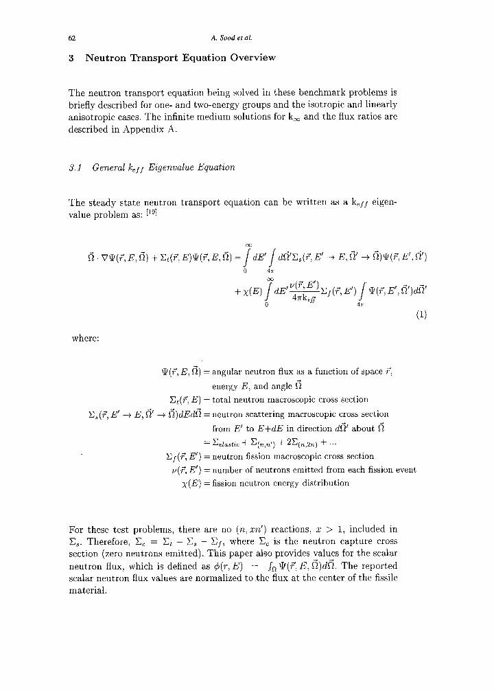
The steady state neutron transport equation can be written as a k,,/ eigen- value problem as: [lgl
6. V'J?(T, E, 6) + C,(F, E)‘l’(F, E, f=i) = jdE’ / df=i’C,(,7, E’ -+ E, 6’ + i=i)S(F, E', 6’) 0 47r
co
+ x(E) /a’ 4rkefS
V(T:B)C#, E’) ,- Q(r’, E’, fi’)dfj’
0 4s
(1)
where:
xq7,E,fi)= an u ar neutron flux as a function of space ?, g 1
energy E, and angle 6
C,(?, E) = total neutron macroscopic cross section
X,(7, E’ --+ E, 6’ -+ 6)dEdfi = neutron scattering macroscopic cross section
from E’ to E+dE in direction $6’ about 6
=C elastic + qL,,,) + 2qL,2,) + ...
C,(T, E’) = neutron fission macroscopic cross section
v(?, E’) = number of neutrons emitted from each fission event
x(E) = fission neutron energy distribution
For these test problems, there are no (n, ZX’) reactions, z > 1, included in C,. Therefore, C, = Ct - C, - C,, where C, is the neutron capture cross section (zero neutrons emitted). This paper also provides values for the scalar
neutron flux, which is defined as 4(r, E) = Jo S(?, E, 6)dfi. The reported scalar neutron flux values are normalized to .the flux at the center of the fissile
material.
Criticality code verification 63
The keff eigenvalue is only associated with the fission reaction and no other
multiplying process such as (n, an). The fundamental eigenvalue, k,f/, is unity
for a critical system, less than unity for a subcritical system, and greater than unity for a supercritical system. The steady state k,fl eigenvalue equation is
physically correct only when k,,, is unity and there is no decay or growth in
\IT(r, E, 6). A solution when k,ff is not unity is still a valuable indicator of the ability of a system to sustain a fission chain reaction. When an infinite
medium is considered, k,ff will be referred to as k,. This paper gives results for the fundamental eigenvalue. For higher eigenvalue results see references
Pal, WI, PI, P41, 1251, WI, P71.
3.2 One-Energy Group in One-Dimensional Slab Geometry
3.2.1 Isotropic Scattering.
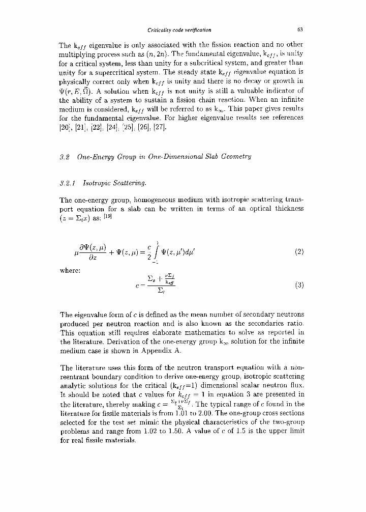
The one-energy group, homogeneous medium with isotropic scattering trans- port equation for a slab can be written in terms of an optical thickness
(.z = Ctz) as: [lgl
paw> I-1) dZ
where:
c= L + 2
Et (3)
The eigenvalue form of c is defined as the mean number of secondary neutrons
produced per neutron reaction and is also known as the secondaries ratio. This equation still requires elaborate mathematics to solve as reported in the literature. Derivation of the one-energy group k, solution for the infinite
medium case is shown in Appendix A.
The literature uses this form of the neutron transport equation with a non- reentrant boundary condition to derive one-energy group, isotropic scattering analytic solutions for the critical (k,,,= 1) dimensional scalar neutron flux.
It should be noted that c values for Ic,ff = 1 in equation 3 are presented in
the literature, thereby making c = v. The typical range of c found in the
literature for fissile materials is from 1.01 to 2.00. The one-group cross sections selected for the test set mimic the physical characteristics of the two-group problems and range from 1.02 to 1.50. A value of c of 1.5 is the upper limit for real fissile materials.
64 A. Sood et al.
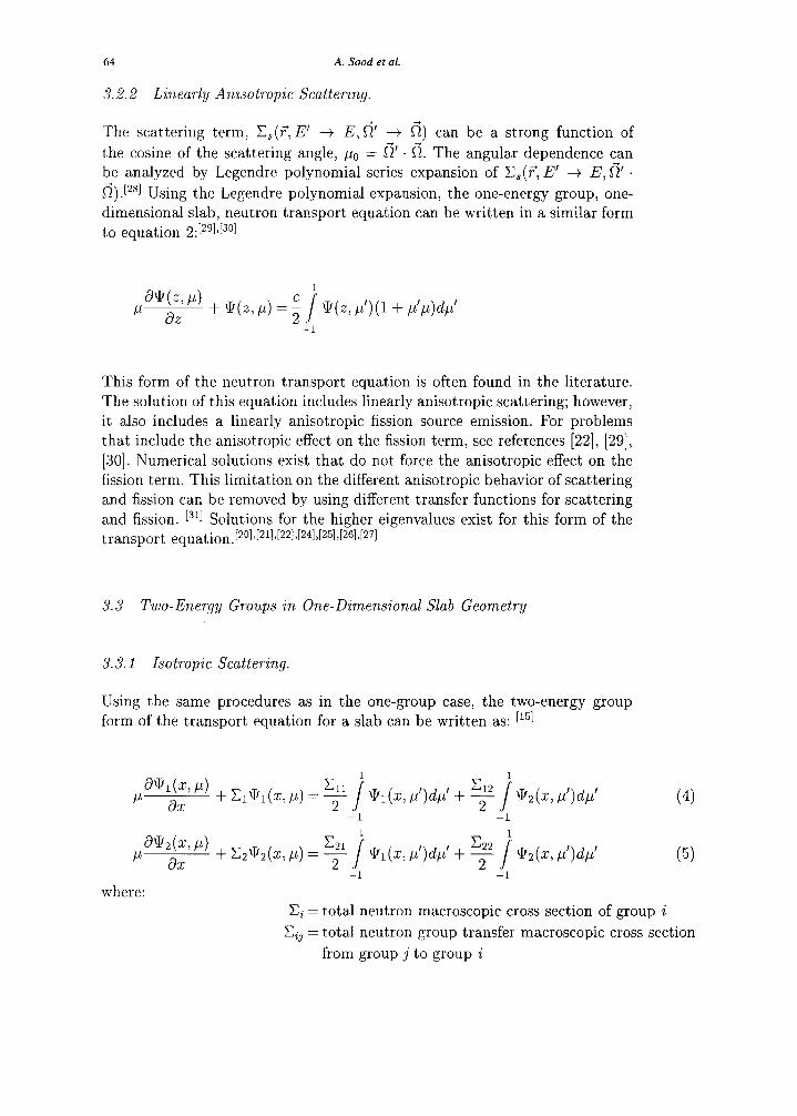
3.2.2 Linearly Anisotropic Scattering.
The scattering term, Cs(?, E’ + E, 6’ + 6) can be a strong function of
the cosine of the scattering angle, p. = 6’ . 6. The angular dependence can be analyzed by Legendre polynomial series expansion of CB(?, E’ + E, 6’ .
f~).[~~l Using the Legendre polynomial expansion, the one-energy group, one- dimensional slab, neutron transport equation can be written in a similar form
to equation 2:[2gIJ301
This form of the neutron transport equation is often found in the literature. The solution of this equation includes linearly anisotropic scattering; however,
it also includes a linearly anisotropic fission source emission. For problems that include the anisotropic effect on the fission term, see references [22], [29],
[30]. Numerical solutions exist that do not force the anisotropic effect on the fission term. This limitation on the different anisotropic behavior of scattering and fission can be removed by using different transfer functions for scattering
and fission. L3rI Solutions for the higher eigenvalues exist for this form of the transport equation.[20I,[21I,[22I,[24I,[25I,[26I,[271
3.3 Two-Eneqy Groups in One-Dimensional Slab Geometry
3.3.1 Isotropic Scattering.
Using the same procedures as in the one-group case, the two-energy group
form of the transport equation for a slab can be written as: Ir51
(4)
(5)
where: Ci = total neutron macroscopic cross section of group i
Cij = total neutron group transfer macroscopic cross section
from group j to group i
Criticality code verification 65
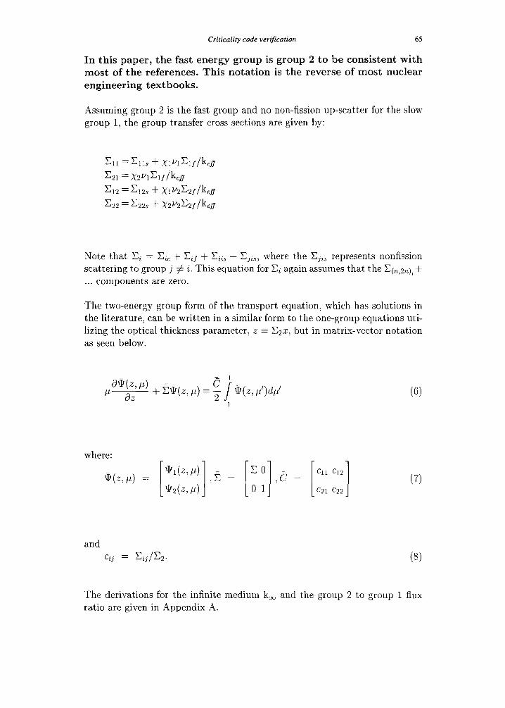
In this paper, the fast energy group is group 2 to be consistent with most of the references. This notation is the reverse of most nuclear
engineering textbooks.
Assuming group 2 is the fast group and no non-fission up-scatter for the slow group 1, the group transfer cross sections are given by:
Note that Ci = C;, + Cif + Ciis + C+, where the Cji, represents nonfission scattering to group j # i. This equation for Ci again assumes that the C(n,2n),+ . . . components are zero.
The two-energy group form of the transport equation, which has solutions in the literature, can be written in a similar form to the one-group equations uti-
lizing the optical thickness parameter, z = C~Z, but in matrix-vector notation as seen below.
where:
W, P) =
(6)
(7)
and Cij = Cij/C2. (8)
The derivations for the infinite medium k, and the group 2 to group 1 flux
ratio are given in Appendix A.
66 A. Sood et al.
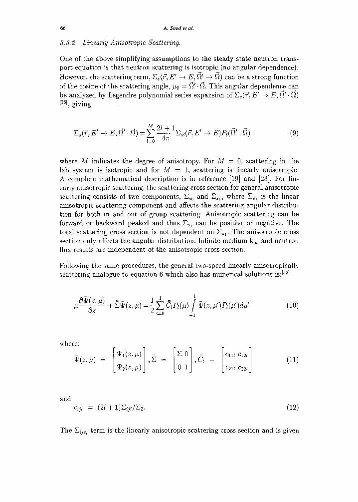
3.3.2 Linearly Anisotropic Scattering.
One of the above simplifying assumptions to the steady state neutron trans- port equation is that neutron scattering is isotropic (no angular dependence).
However, the scattering term, CS(?‘, E’ + E, fi’ -+ 6) can be a strong function
of the cosine of the scattering angle, p. = 6’. R. This angular dependence can
be analyzed by Legendre polynomial series expansion of I&(?, E’ + E, 6’ ’ 6)
L2W, giving
M 21+1 C$, E’ -+ E, 6’ . 6) = c -&(F, E’ + E)P$=i’ . 6)
133 47r
where A4 indicates the degree of anisotropy. For M = 0, scattering in the lab system is isotropic and for M = 1, scattering is linearly anisotropic.
A complete mathematical description is in reference [19] and [28]. For lin- early anisotropic scattering, the scattering cross section for general anisotropic
scattering consists of two components, C,, and C,,, where C,, is the linear anisotropic scattering component and affects the scattering angular distribu-
tion for both in and out of group scattering. Anisotropic scattering can be forward or backward peaked and thus C,, can be positive or negative. The
total scattering cross section is not dependent on C,,. The anisotropic cross section only affects the angular distribution. Infinite medium k, and neutron flux results are independent of the anisotropic cross section.
Following the same procedures, the general two-speed linearly anisotropically scattering analogue to equation 6 which also has numerical solutions is:[32]
where:
*(W) =
and
Cijl = (21 + l&j~/&.
(10)
(11)
(12)
The C,,, term is the linearly anisotropic scattering cross section and is given
Criticality code verification 67
in the problem descriptions without the (26 + 1) term.
4 One-Energy Group Problem Definitions and Results
For the one-energy group cases, the critical dimension(s) for each geometry depends upon the c value chosen from the literature and not specific cross section sets. To use the literature results, the cross sections were selected to
match published c values with k,,,= 1 at low, middle, and high c values listed.
Values ranging from 1.02, 1.30, 1.40, and 1.50 were chosen because they are similar to the physical systems in the two-group cases: uranium-DzO reactor,
U-235, and Pu-239. These problems use cross sections that are reasonable rep- resentations of these materials; however, these cross sections are not general purpose one-group values. The cross sections are used because they define the
c values used in the literature and are intended to be used only to verify al- gorithm performance and not to predict any actual criticality experiments. Cross section values are assumed accurate to the number of decimal places reported.
The isotropic neutron macroscopic cross sections provided for each case are: the total cross section, Et, the capture (no neutrons emitted) cross section,
C,, the scattering cross section, C,, the fission cross section, C,, and the number of neutrons, v, emitted for each fission. The (n,2n), (n,3n), . . . cross
sections are assumed to be zero (but need not be). Thus the total cross section equals the sum of C,, C,, and C,, thereby providing a consistency check on the cross section set. Many references give (IIC,) instead of v and Cf. Since both parameters (not the product) may be required by a code for the problem solution, the product (VIE,) has been split into v and C, preserving their
product and Ct. The value of c for k,ff=l in equation 6 is also included in each cross section table. For the reflected spheres, different secondaries ratios, c, are reported with the critical dimension for k,,,=l for various combinations of core and reflector thicknesses. To maintain consistent cross sections with
the U-235 set, the parameter, v, was modified to match c to the literature values.
When anisotropic scattering cross sections are provided, the anisotropic com- ponents are designated by C,, and C,,, respectively. Similarly, the isotropic scattering component is designated by C,,.
The value of k,, as defined in Appendix A, is given for each cross section set. For finite problems where k,ff is unity, the critical dimension, r,, is listed for each geometry in both mean free paths (to indicate the neutron optical thick- ness) and in centimeters for the one-dimensional geometries. When available in the literature, the scalar flux values, normalized to the flux at the center
68 A. Sood et al.
of the fissile material, are also provided. The two-media problems have cl > 1 for the core region 1 and c2 < 1 for the surrounding reflector region 2. The
two-media problems use the cross sections for the nonmultiplying reflector. The critical dimensions for the multiplying medium and reflector thickness
are given in both mean free paths and centimeters.
A comparison of the critical dimensions for the different geometries behave as expected; that is, the critical dimension is smallest for the one-dimensional
slab and increases for the cylinder and sphere. This behavior is to be expected due to the increased leakage with the curvi-linear geometries. For the reflect,ed
geometries, the critical dimension decreases with increasing reflector thickness.
Criticality code verification
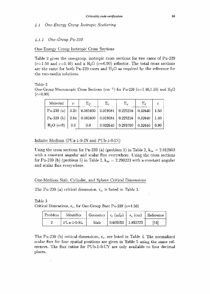
4.1 One-Ener.gy Group Isotropic Scattering
69
4.1.1 One- Group Pu-239.
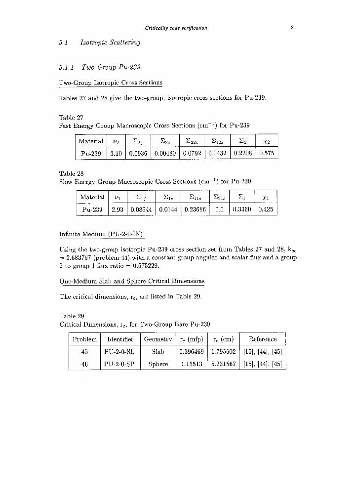
One-Energy Group Isotropic Cross Sections
Table 2 gives the one-group, isotropic cross sections for two cases of Pu-239
(c=1.50 and c=1.40) and a Hz0 (c=O.90) reflector. The total cross sections are the same for both Pu-239 cases and Hz0 as required by the reference for
the two-media solutions.
Table 2 One-Group Macroscopic Cross Sections (CIKl) for Pu-239 (c=1.40,1.50) and Hz0 (c=O.SO)
Material v Cf cc Es & C
Pu-239 (a) 3.24 0.081600 0.019584 0.225216 0.32640 1.50
Pu-239 (b) 2.84 0.081600 0.019584 0.225216 0.32640 1.40
Hz0 (refl) 0.0 0.0 0.032640 0.293760 0.32640 0.90
Infinite Medium (PUa-l-O-IN and Pub-l-O-IN)
Using the cross sections for Pu-239 (a) (problem 1) in Table 2, k, = 2.612903 with a constant angular and scalar flux everywhere. Using the cross sections for Pu-239 (b) (problem 5) in Table 2; k, = 2.290323 with a constant angular and scalar flux everywhere.
One-Medium Slab, Cylinder, and Sphere Critical Dimensions
The Pu-239 (a) critical dimension, rc; is listed in Table 3.
Table 3 Critical Dimensions, rc, for One-Group Bare Pu-239 (c=1.50)
Problem Identifier Geometry r, (mfp) rc (cm) Reference
2 PUa-l-0-SL Slab 0.605055 1.853722 [161
The Pu-239 (b) critical dimensions, r,, are listed in Table 4. The normalized scalar flux for four spatial positions are given in Table 5 using the same ref- erences. The flux ratios for Pub-l-0-CY are only available to four decimal places.
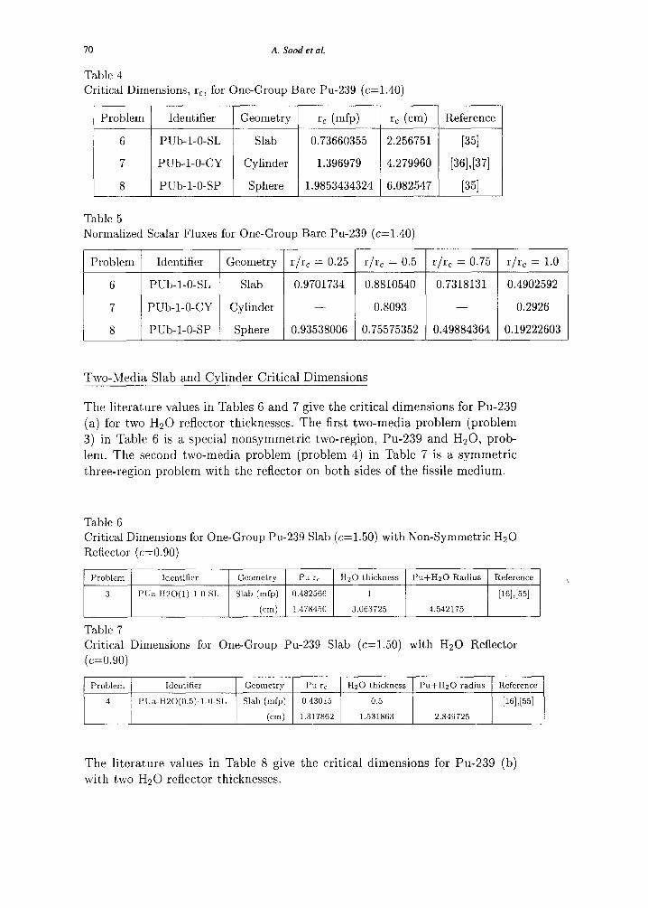
A. Sood et al. 70
Table 4
Critical Dimensions, rc, for One-Group Bare Pu-239 (c=1.40)
Problem Identifier Geometry rc (mfp) rc (cm) Reference
6 Pub-l-0-SL Slab 0.73660355 2.256751 [351
7 Pub-I-0-CY Cylinder 1.396979 4.279960 [361,[371
8 Pub-l-0-SP Sphere 1.9853434324 6.082547 [351
Table 5
Normalized Scalar Fluxes for One-Group Bare Pu-239 (c=1.40)
Problem Identifier Geometry r r, = 0.25 I 1
6 Pub-l-0-SL Slab 0.9701734
7 Pub-l-0-CY Cylinder
8 Pub-l-0-SP Sphere 0.93538006
r/r, = 0.5 r/r, = 0.75 r/r, = 1.0
0.8810540 0.7318131 0.4902592
0.8093 0.2926
0.75575352 0.49884364 0.19222603
Two-Media Slab and Cvlinder Critical Dimensions
The literature values in Tables 6 and 7 give the critical dimensions for Pu-239
(a) for two Hz0 reflector thicknesses. The first two-media problem (problem
3) in Table 6 is a special nonsymmetric two-region, Pu-239 and H20, prob-
lem. The second two-media problem (problem 4) in Table 7 is a symmetric
three-region problem with the reflector on both sides of the fissile medium.
Table 6
Critical Dimensions for One-Group Pu-239 Slab (c=1.50) with Non-Symmetric Hz0
Reflector (c=O.90)
Problem Identifier Geometry Pu rc Hz0 thickness Pu+HzO Radius Reference
3 PUa-HZO(l)-1.0-SL Slab (mfp) 0.482566 1 [161,[551
(cm) 1.478450 3.063725 4.542175
Table 7
Critical Dimensions for One-Group Pu-239 Slab (c=1.50) with Hz0 Reflector
(c=O.90)
Problem Identifier Geometry Pu rc Hz0 thickness Pu+HzO radius Reference
4 PUa-H20(0.5)-I-0-Z Slab (mfp) 0.43015 0.5 [161,[551
(cm) 1.317862 1.531863 2.849725
The literature values in Table 8 give the critical dimensions for Pu-239 (b)
with two Hz0 reflector thicknesses.
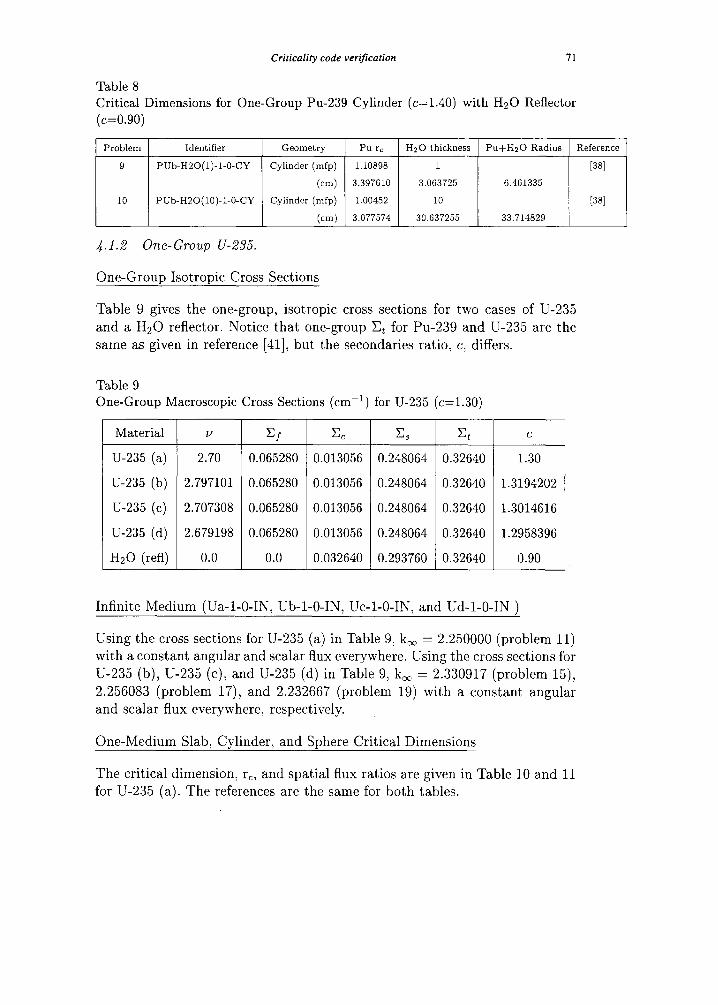
Criricalify code verificafion 71
Table 8 Critical Dimensions for One-Group Pu-239 Cylinder (c=1.40) with Hz0 Reflector
(c=O.90)
Problem Identifier Geometry Pu rc Hz0 thickness Pu+HzO Radius Reference
9 Pub-HSO(l)-l-0-CY Cylinder (mfp) 1.10898 1 [381
(cm) 3.397610 3.063725 6.461335
10 PUb-H20(10)-l-0.CY Cylinder (mfp) 1.00452 10 [381
(cm) 3.077574 30.637255 33.714829
4.1.2 One-Group U-235.
One-Group Isotropic Cross Sections
Table 9 gives the one-group, isotropic cross sections for two cases of U-235 and a H20 reflector. Notice that one-group CL for Pu-239 and U-235 are the
same as given in reference [41], but the secondaries ratio, c; differs.
Table 9 One-Group Macroscopic Cross Sections (cm-l) for U-235 (c=1.30)
u
2.70
2.797101
2.707308
2.679198
0.0
=f
0.065280
0.065280
0.065280
0.065280
0.0
0.013056 0.248064 0.32640 1.30
0.013056 0.248064 0.32640 1.3194202
0.013056 0.248064 0.32640 1.3014616
0.013056 0.248064 0.32640 1.2958396
0.032640 0.293760 0.32640 0.90
Infinite Medium (Ua-l-O-IN, Ub-l-O-IN, UC-~-O-IN, and Ud-l-O-IN )
Using the cross sections for U-235 (a) in Table 9; k, = 2.250000 (problem 11)
with a constant angular and scalar flux everywhere. Using the cross sections for
U-235 (b), U-235 (c), and U-235 (d) in Table 9, k, = 2.330917 (problem 15), 2.256083 (problem 17), and 2.232667 (problem 19) with a constant angular and scalar flux everywhere, respectively.
One-Medium Slab, Cylinder, and Sphere Critical Dimensions
The critical dimension, rcr and spatial flux ratios are given in Table 10 and 11 for U-235 (a). The references are the same for both tables.
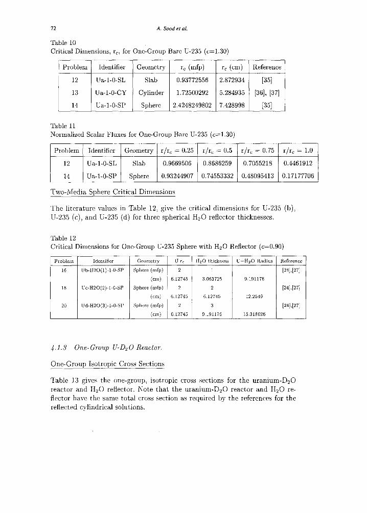
12 A. Sood et al.
Table 10
Critical Dimensions, rc, for One-Group Bare U-235 (c=1.30)
Problem Identifier ) Geometry ) r, (mfp) ) I’, (cm) 1 Reference
12 Ua-l-0-SL Slab 0.93772556 2.872934 1351
13 Ua-l-0-CY Cylinder 1.72500292 5.284935 [36], [37]
14 Ua-l-0-SP Sphere 2.4248249802 7.428998 [351
Table 11
Normalized Scalar Fluxes for One-Group Bare U-235 (c=1.30)
Problem Identifier Geometry 1 r/r, = 0.25 1 r/r, = 0.5 1 r/r, = 0.75 ( r/rc = 1.0
1 :; 1 ;~;;a-;;; 1 ,%b, ( 0.9669506 / 0.8686259 j 0.7055218 / 0.4461912
0.93244907 0.74553332 0.48095413 0.17177706 _
Two-Media Sphere Critical Dimensions
The literature values in Table 12, give the critical dimensions for U-235 (b),
U-235 (c), and U-235 (d) for three spherical H20 reflector thicknesses.
Table 12
Critical Dimensions for One-Group U-235 Sphere with Hz0 Reflector (c=O.90)
Problem Identifier Geometry U rc Hz0 thickness U+HzO Radius Reference
16 Ub-HZO(l)-l-O-SP Sphere (mfp) 2 1 [241,[271
(cm) 6.12745 3.063725 9.191176
18 UC-H20(2)-1.O-SP Sphere (mfp) 2 2 [241,[271
(cm) 6.12745 6.12745 12.2549
20 Ud-H20(3)-1.C-SP Sphere (mfp) 2 3 [241>[271
(cm) 6.12745 9.191176 15.318626
4.1.3 One-Group U-D20 Reactor.
One-Group Isotropic Cross Sections
Table 13 gives the one-group, isotropic cross sections for the uranium-D20
reactor and Hz0 reflector. Note that the uranium-D20 reactor and Hz0 re-
flector have the same total cross section as required by the references for the
reflected cylindrical solutions.
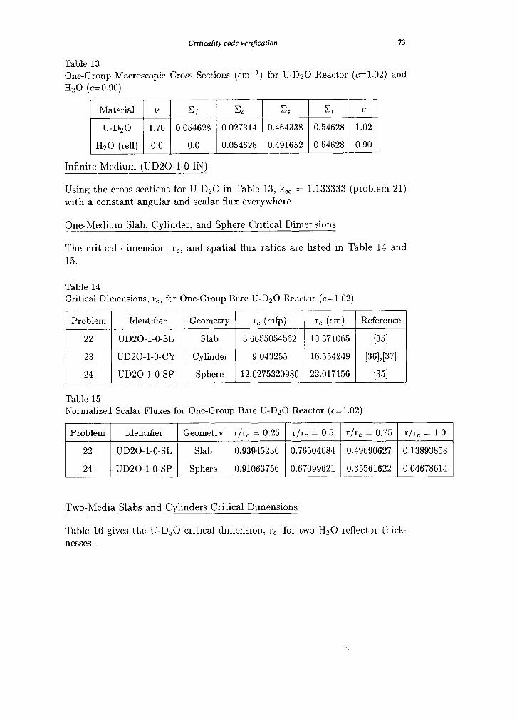
Criticality code verftcarion 13
Table 13
One-Group Macroscopic Cross Sections (cm-l) for U-D20 Reactor (c=1.02) and
Hz0 (c=O.90)
Material v Cf c, c, Et C
U-D20 1.70 0.054628 0.027314 0.464338 0.54628 1.02
Hz0 (refl) 0.0 0.0 0.054628 0.491652 0.54628 0.90
Infinite Medium (UD20-l-O-IN)
Using the cross sections for U-D20 in Table 13, k, = 1.133333 (problem 21)
with a constant angular and scalar flux everywhere.
One-Medium Slab, Cylinder, and Sphere Critical Dimensions
The critical dimension, r,, and spatial flux ratios are listed in Table 14 and
15.
Table 14 . .
CrItIcal Dimensions, rcr for One-Group Bare U-D20 Reactor (c=1.02)
Problem Identifier Geometry rc (mfp) rc (cm) Reference
22 UD20-l-0-SL Slab 5.6655054562 10.371065 [351
23 UD20-l-0-CY Cylinder 9.043255 16.554249 [361,[371
24 UD20-l-0-SP Sphere 12.0275320980 22.017156 1351
Table 15
Normalized Scalar Fluxes for One-Group Bare U-D20 Reactor (c=1.02)
Problem Identifier Geometry r/r, = 0.25 r/r, = 0.5 r/rc = 0.75 r/r, = 1.0
22 UD20-l-0-SL Slab 0.93945236 0.76504084 0.49690627 0.13893858
24 UD20-l-0-SP Sphere 0.91063756 0.67099621 0.35561622 0.04678614
Two-Media Slabs and Cylinders Critical Dimensions
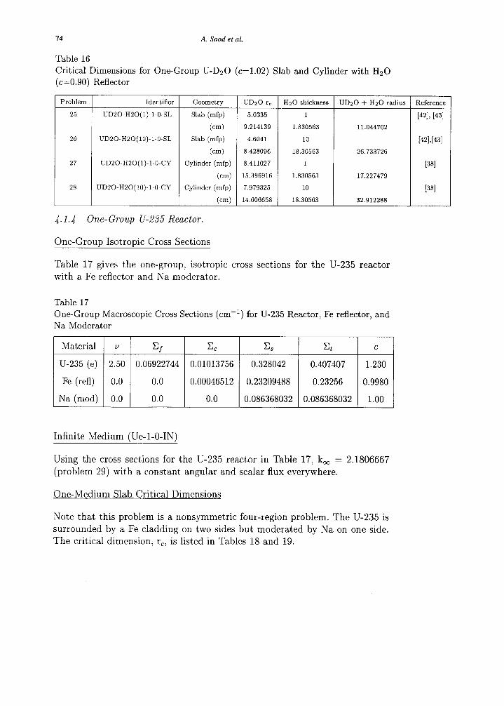
Table 16 gives the U-D20 critical dimension, r,; for two Hz0 reflector t’hick-
nesses.
74
Table 16
A. Sood et al.
Critical Dimensions for One-Group U-D20 (c=1.02) Slab and Cylinder with Hz0
(c=O.90) Reflector
Problem
25
Identifier
I;D20-H20(1)-1.O-SL
26 UD20-H20(10)-1.0.SL
27
28
UD20-H20(1)-1.0.CY
UD20-H20(10)-l-O-CY
Geometry UDzO rc
Slab (mfp) 5.0335
(cm) 9.214139
Slab (mfp) 4.6041
(cm) 8.428096
Cylinder (mfp) 8.411027
(cm) 15.396916
Cylinder (mfp) 7.979325
(cm) 14.606658
4.1.4 One-Group U-235 Reactor.
One-Groun Isotronic Cross Sections
I Hz0 thickness UDzO + Hz0 radius
1
1.830563 11.044702
10
18.30563 26.733726
1
1.830563 17.227479
10
18.30563 32.912288
Table 17 gives the one-group, isotropic cross sections for the U-235 reactor with a Fe reflector and Na moderator.
Table 17
One-Group Macroscopic Cross Sections (cm-l) for U-235 Reactor, Fe reflector, and
Na Moderator
Material v Cf cc Es & C
U-235 (e) 2.50 0.06922744 0.01013756 0.328042 0.407407 1.230
Fe (refl) 0.0 0.0 0.00046512 0.23209488 0.23256 0.9980
Na (mod) 0.0 0.0 0.0 0.086368032 0.086368032 1.00
Infinite Medium (Ue-l-O-IN)
Using the cross sections for the U-235 reactor in Table 17, k, = 2.1806667 (problem 29) with a constant angular and scalar flux everywhere.
One-Medium Slab Critical Dimensions
Reference
[421, [431
[4%[431
[381
[381
Note that this problem is a nonsymmetric four-region problem. The U-235 is surrounded by a Fe cladding on two sides but moderated by Na on one side. The critical dimension, rcr is listed in Tables 18 and 19.
Criticality code verification 15
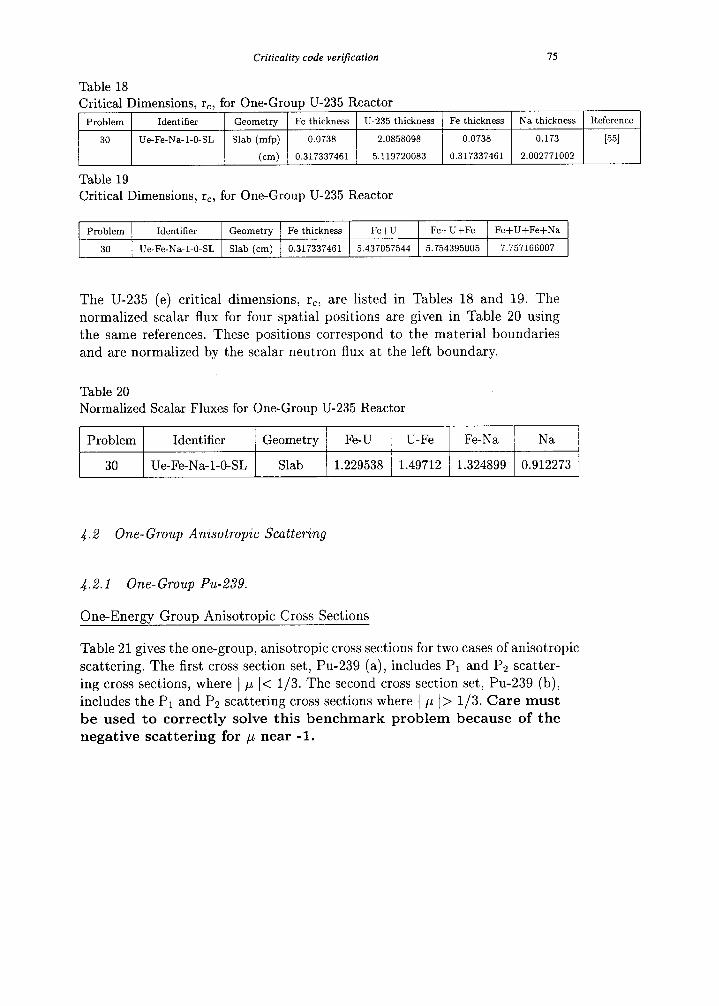
Table 18
Critical Dimensions, rc, for One-Group U-235 Reactor
Problem Identifier Geometry Fe thickness U-235 thickness Fe thickness Na thickness Reference
30 Ue-Fe-Na-l-0-SL Slab (mfp) 0.0738 2.0858098 0.0738 0.173 [551
(cm) 0.317337461 5.119720083 0.317337461 2.002771002
Table 19
Critical Dimensions, rc, for One-Group U-235 Reactor
Problem Identifier Geometry Fe thickness Fe+U Fe+U+Fe Fe+U+Fe+Na
30 Ue-Fe-Na-1-0-SL Slab (cm) 0.317337461 5.437057544 5.754395005 7.757166007
The U-235 (e) critical dimensions, rc, are listed in Tables 18 and 19. The normalized scalar flux for four spatial positions are given in Table 20 using the same references. These positions correspond to the material boundaries
and are normalized by the scalar neutron flux at the left boundary.
Table 20
Normalized Scalar Fluxes for One-Group U-235 Reactor
Problem Identifier Geometry Fe-U U-Fe Fe-Na Na
30 Ue-Fe-Na-l-0-SL Slab 1.229538 1.49712 1.324899 0.912273
4.2 One- Group Anisotropic Scattering
4.2.1 One-Group Pu-239.
One-Energy Group Anisotropic Cross Sections
Table 21 gives the one-group, anisotropic cross sections for two cases of anisotropic
scattering. The first cross section set, Pu-239 (a), includes P1 and Pz scatter- ing cross sections, where 1 /-I I< l/3. Th e second cross section set, Pu-239 (b), includes the Pl and P2 scattering cross sections where ( ,LL I> l/3. Care must be used to correctly solve this benchmark problem because of the negative scattering for /_A near -1.
16 A. Sood et al.
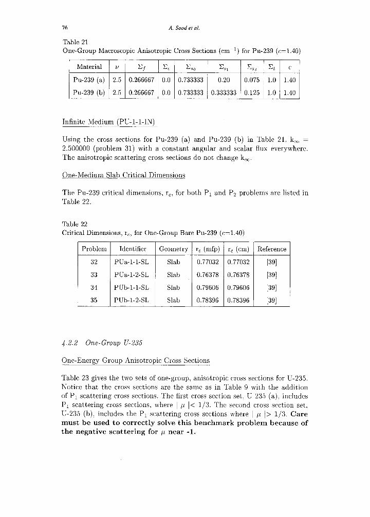
Table 21 One-Group Macroscopic Anisotropic Cross Sections (cm-‘) for Pu-239 (c=1.40)
Material v CJ & %, =s, c s2 Et c
Pu-239 (a) 2.5 0.266667 0.0 0.733333 0.20 0.075 1.0 1.40
Pu-239 (b) 2.5 0.266667 0.0 0.733333 0.333333 0.125 1.0 1.40
Infinite Medium (PU-l-l-IN)
Using the cross sections for Pu-239 (a) and Pu-239 (b) in Table 21, k, =
2.500000 (problem 31) with a constant angular and scalar flux everywhere. The anisotropic scattering cross sections do not change k,.
One-Medium Slab Critical Dimensions
The Pu-239 critical dimensions, r,, for both Pi and P2 problems are listed in
Table 22.
Table 22 Critical Dimensions, rc, for One-Group Bare Pu-239 (c=1.40)
Problem Identifier Geometry rc (mfp) r, (cm) Reference
32 PUa-l-l-SL Slab 0.77032 0.77032 P91 33 PUa-l-2-SL Slab 0.76378 0.76378 WI 34 Pub-l-l-SL Slab 0.79606 0.79606 WI 35 Pub-I-2-SL Slab 0.78396 0.78396 [391
4.2.2 One-Group U-235
One-Energy Group Anisotropic Cross Sections
Table 23 gives the two sets of one-group, anisotropic cross sections for U-235. Notice that the cross sections are the same as in Table 9 with the addition of P1 scattering cross sections. The first cross section set, U-235 (a), includes Pi scattering cross sections, where / p I< l/3. The second cross section set, U-235 (b); includes the PI scattering cross sections where 1 p I> l/3. Care
must be used to correctly solve this benchmark problem because of
the negative scattering for 1-1 near -1.

Criticality code verification 77
Table 23 One-Group Macroscopic Anisotropic Cross Sections (cm-i) for U-235 (c=1.30)
Material v CJ cc c SO cs, Et c
U-235 (a) 2.70 0.065280 0.013056 0.248064 0.042432 0.32640 1.30
U-235 (b) 2.70 0.065280 0.013056 0.248064 0.212160 0.32640 1.30
Infinite Medium (U-l-l-IN)
Using the cross sections for U-235 (a) and U-235 (b) in Table 23, k, = 2.250000 (problem 11) with a constant angular and scalar flux everywhere. The anisotropic scattering cross sections do not change k,.
One-Medium Slab Critical Dimensions
The U-235 critical dimensions, r,, for both Pi problems are listed in Table 24.
Table 24 . .
Critical Dimensions, rc, for One-Group Bare U-235 (c=1.30)
Problem Identifier Geometry rc (mfp) rc (cm) Reference
36 Ua-l-l-CY Cylinder 1.799866479 5.514296811 [401
37 Ub-l-l-CY Cylinder 2.265283130 6.940205668 PO1
4.2.3 One-Group U-D2 0
One-Energy Group Anisotropic Cross Sections
Table 25 gives the two sets of one-group, anisotropic cross sections for U- D20 reactor. Notice that the cross sections are the same as in Table 13 with
the addition of Pr scattering cross sections. The cross sections set for two
U-D20 cases include Pi scattering cross sections, where 1 p I< l/3, and a Pi case where p < 0 and the scattering cross section is negative. Care must
be used to correctly solve this benchmark problem because of the negative scattering for p near -1.
Infinite Medium UD20a-l-l-IN, UD20b-l-l-IN, and UD20c-l-l-IN
Using the cross sections for U-D20 (a), U-D20 (b), and U-D20 (c) in Table 25, k, = 1.205587 (problem 38); 1.227391 (problem 40), and 1.130933 (problem 42); respectively, with a constant angular and scalar flux everywhere. The
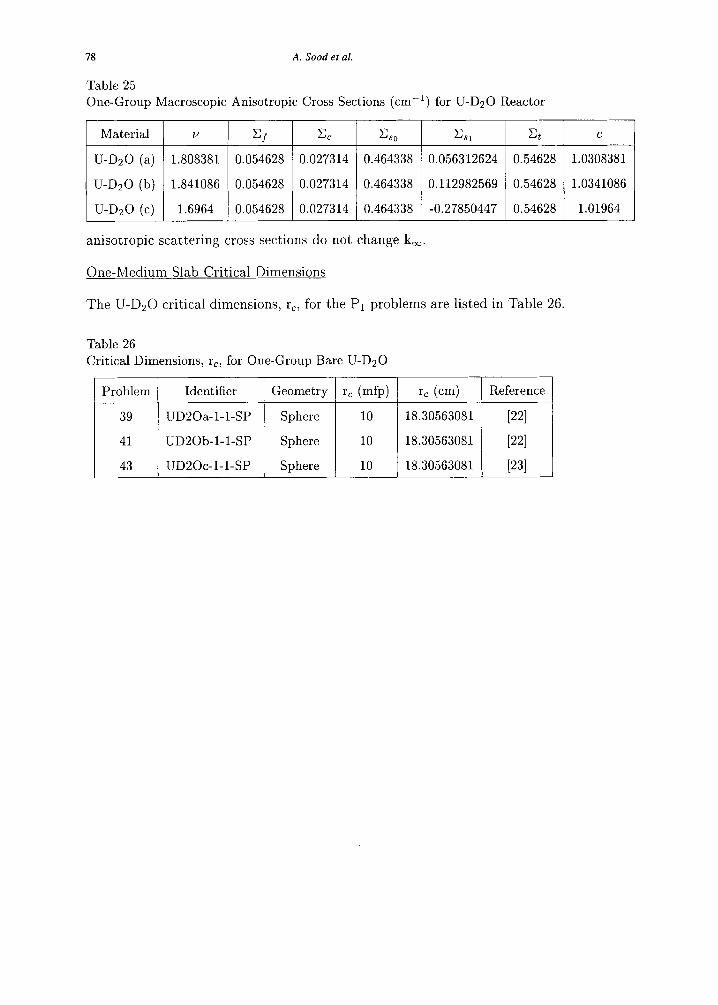
78 A. Sood et al.
Table 25
One-Group Macroscopic Anisotropic Cross Sections (cm-‘) for U-D20 Reactor
Material v c/ c, c so x5x Et c
U-D20 (a) 1.808381 0.054628 0.027314 0.464338 0.056312624 0.54628 1.0308381
U-D20 (b) 1.841086 0.054628 0.027314 0.464338 0.112982569 0.54628 1.0341086
U-D20 (c) 1.6964 0.054628 0.027314 0.464338 -0.27850447 0.54628 1.01964
anisotropic scattering cross sections do not change k,.
One-Medium Slab Critical Dimensions
The U-D20 critical dimensions, rc, for the Pi problems are listed in Table 26.
Table 26
Critical Dimensions, rc, for One-Group Bare U-D20
Problem Identifier Geometry r, (mfp) rc (cm) Reference
39 UD20a-l-I-SP Sphere 10 18.30563081 PI
41 UD20b-l-l-SP Sphere 10 18.30563081 1221
43 UD20c-l-l-SP Sphere 10 18.30563081 [231

Criticality code verification 19
5 Two-Energy Group Problem Definitions and Results
The isotropic two-energy group cross sections for five bare and two water re-
flected cases are listed in this section. There are also two linearly anisotropic scattering cross sections sets provided for bare and infinite medium reactors. Unlike the one-group case, there is no flexibility in choosing these values since
they are used throughout the literature. The cross sections listed here are similar to Pu-239, L411 U-235,r41] a realistic enriched uranium-aluminum-water
assembly [r51, a 93% enriched U-235 model of a university research reactor, [151~[441~[451 and a typical large size D20 reactor with low enrichment of U- 235.[‘51,[441,[451 Al so included are critical dimensions for a similar uranium re-
search reactor with a water reflector in an infinite lattice.[43] Again, these problems use cross sections that are reasonable representations of the materi- als described. These cross sections are not general purpose two-group values.
The cross sections are used because they are defined in the literature and are intended to be used only to verify algorithm performance and not to predict
any actual criticality experiments.
The isotropic neutron cross macroscopic sections (cm-‘) provided for these
problems are the total cross section of group i, Xi, the capture (no neutrons emitted) cross section, CCi, the within group scattering cross section: &is: the group-to-group scattering cross sections, Cij, and Cjis7 the fission cross
section, I+, the number of neutrons, vi, emitted from each fission in a group, and the fission distribution, xi.
In this paper, the fast energy group is group 2 to be consistent with most of the references. This notation is the reverse of most nuclear engineering textbooks.
The literature solutions are often based on the group transfer cross sections, Xii, given in the references; therefore, the individual cross sections may not be
unique. Most references give (YC,)~ instead of vi and Cfi. Since both param- eters (not the product) may be required by a code for the problem solution,
the product (vC,)~ has been split into Vi and C/i preserving their product and Ct. The infinite slab lattice problems use a slightly unphysical set of cross
sections to possibly stress code verification.
The two sets of linearly anisotropic cross sections provided are extensions of
the university research reactor and DzO cases. [32) The anisotropic scattering
component is designated for the in-group and group-to-group scattering cross section by Ciisl and Cjis,, respectively. Similarly, the isotropic scattering com- ponent is designated by Ciiso and CjisO.
The value for k, is given for each cross section set. For finite problems, the crit- ical dimension, rC, is listed in both fast group mean free paths (to indicate the
80 A. Sood et al.
neutron optical thickness) and in centimeters. For two-media problems, critical dimensions for the inner multiplying medium and outer reflector thickness are
given in both fast mean free paths and centimeters. The critical dimensions, r,, and reflector half thicknesses are also given for a water reflected infinite
slab lattice cell. Flux values are given for the university research reactor (a) (problems 54 and 71) at four spatial points. Angular fluxes can be found in the dissertation references.
To distinguish between the different URR fissile material cross section sets; each is labeled with a letter “a,” “b,” “c,” or “d”, respectively. The infinite slab lattice cell cross sections are similar to the other three cross section sets for the university research reactor and are labeled with URRd identifiers. The
literature also uses three different Hz0 reflectors. Their cross sections are also labeled with a letter “a, ” 3,” or “2’ in the identifier. URR cross section sets
“b” and “c” have thermal upscattering. All other two-group cross sections have no thermal upscattering.
A comparison of the critical dimensions for the different geometries behave as expected; that is, the critical dimension is smallest for the one-dimensional slab and increases for the cylinder and sphere. This behavior is to be expected due to the increased leakage with the curvi-linear geometries. The effect of
increased leakage on the critical dimension can be also be seen for the forward peaked linear anisotropically scattering cases. For the reflected geometries,
the critical dimension decreases with increasing reflector thickness. However, the critical dimension for the infinite lattice cell increases with the increasing
moderator thickness. Even though this may seem counter-intuitive, it should be expected because the amount of interaction between the fissile medium and adjacent cells decreases with increasing moderator half thickness.[43]
Criticality code verification 81
5.1 Isotropic Scattering
5.1.1 Two- Group Pu-239.
Two-Group Isotropic Cross Sections
Tables 27 and 28 give the two-group, isotropic cross sections for Pu-239.
Table 27 Fast Energy Group Macroscopic Cross Sections (cm-l) for Pu-239
Material ~2 =2f c2c c22s c12s x2 x2
Pu-239 3.10 0.0936 0.00480 0.0792 0.0432 0.2208 0.575
Table 28 Slow Energy Group Macroscopic Cross Sections (cm-‘) for Pu-239
Material ~1 Clf Cl, GlS c21s Cl Xl
Pu-239 2.93 0.08544 0.0144 0.23616 0.0 0.3360 0.425
Infinite Medium (PU-2-O-IN)
Using the two-group isotropic Pu-239 cross section set from Tables 27 and 28, k, = 2.683767 (problem 44) with a constant group angular and scalar flux and a group 2 to group 1 flux ratio = 0.675229.
One-Medium Slab and Sphere Critical Dimensions
. . . The critical dmlenslons, rc, are listed in Table 29.
Table 29 .
Crrtrcal Dimensions, rc, for Two-Group Bare Pu-239
Problem Identifier Geometry r, (mfp) rc (cm) Reference
45 PU-2-o-SL Slab 0.396469 1.795602 [15], [44], [45]
46 PU-2-o-SP Sphere 1.15513 5.231567 [15], [44], [45]
a2
5.1.2 Two- Group U-235.
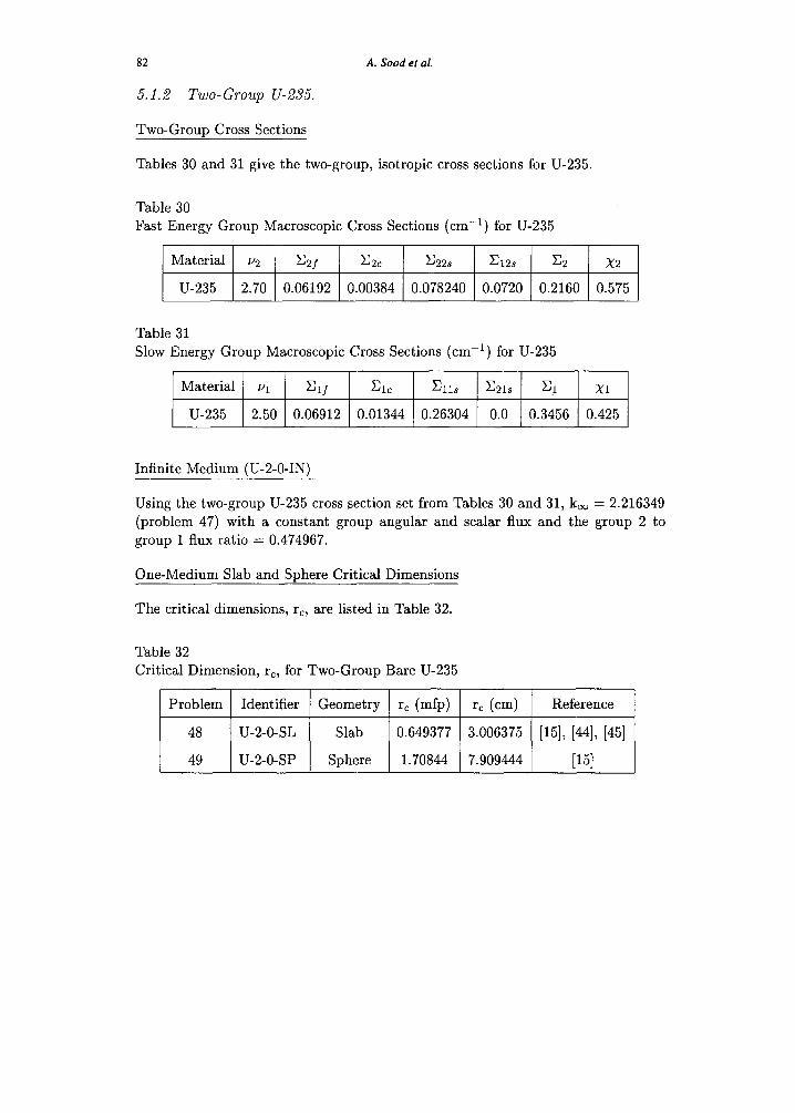
TWO-G~OUD Cross Sections
A. Sood et al.
Tables 30 and 31 give the two-group, isotropic cross sections for U-235.
Table 30 Fast Energy Group Macroscopic Cross Sections (cm-“) for U-235
Material ~2 =2f c2c c22s &2s x2 x2
U-235 2.70 0.06192 0.00384 0.078240 0.0720 0.2160 0.575
Table 31 Slow Energy Group Macroscopic Cross Sections (cm-‘) for U-235
Material ~1 Elf Cl, &lS c21s CL Xl
U-235 2.50 0.06912 0.01344 0.26304 0.0 0.3456 0.425
Infinite Medium (U-2-O-IN)
Using the two-group U-235 cross section set from Tables 30 and 31, k, = 2.216349 (problem 47) with a constant group angular and scalar flux and the group 2 to group 1 flux ratio = 0.474967.
One-Medium Slab and Sphere Critical Dimensions
. . . The crrtrcal dimensions, rc, are listed in Table 32.
Table 32 Critical Dimension, r,, for Two-Group Bare U-235
Problem Identifier Geometry rc (mfp) rc (cm) Reference
48 u-2-o-SL Slab 0.649377 3.006375 [15], [44], [45]
49 u-2-o-SP Sphere 1.70844 7.909444 [I51
Criticality code verification 83
5.1.3 Two-Group Uranium-Aluminum-Water Assembly.
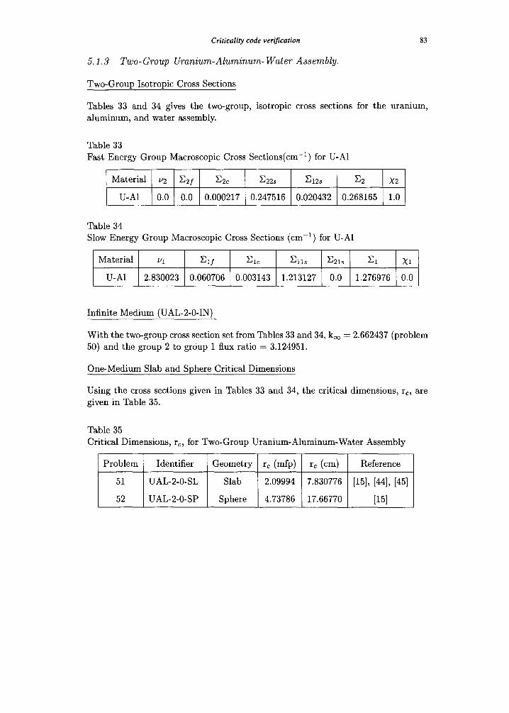
Two-Group Isotropic Cross Sections
Tables 33 and 34 gives the two-group, isotropic cross sections for the uranium, aluminum, and water assembly.
Table 33 Fast Energy Group Macroscopic Cross Sections(cm - i ) for U-A1
Material u2 E2f E2c E22s E12s E2 X2
U-AI 0.0 0.0 0.000217 0.247516 0.020432 0.268165 1.0 [
Table 34 Slow Energy Group Macroscopic Cross Sections (cm -1) for U-A1
Material ~i Ei/ Elc Ells E21s E1
U-A1 2.830023 0.060706 0.003143 1.213127 0.0 1.276976
X1
0.0
Infinite Medium (UAL-2-0-IN)
With the two-group cross section set from Tables 33 and 34, koo -- 2.662437 (problem 50) and the group 2 to group 1 flux ratio = 3.124951.
One-Medium Slab and Sphere Critical Dimensions
Using the cross sections given in Tables 33 and 34, the critical dimensions, rc, are given in Table 35.
Table 35 Critical Dimensions, rc, for Two-Group Uranium-Aluminum-Water Assembly
Problem Identifier Geometry rc (mfp) rc (cm) Reference
51 UAL-2-0-SL Slab 2.09994 7.830776 [15], [44], [45]
52 UAL-2-0-SP Sphere 4.73786 17.66770 [15]
84 A. Sood et al.
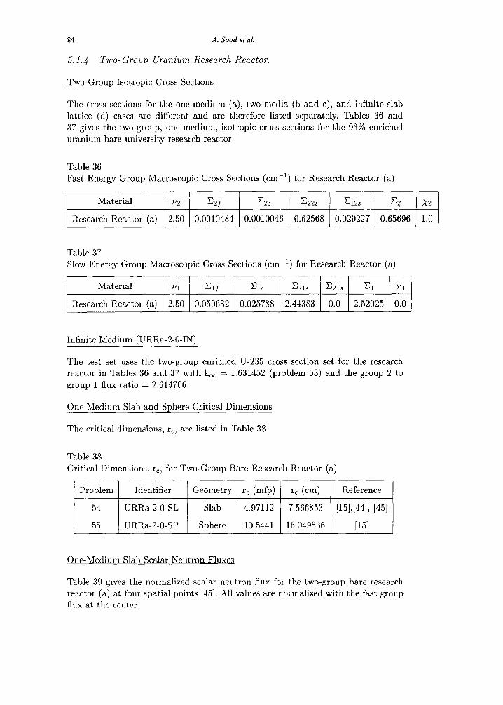
5.1.4 Two-Group Uranium Research Reactor.
Two-Group Isotropic Cross Sections
The cross sections for the one-medium (a), two-media (b and c), and infinite slab
lattice (d) cases are different and are therefore listed separately. Tables 36 and
37 gives the two-group, one-medium, isotropic cross sections for the 93% enriched uranium bare university research reactor.
Table 36
Fast Energy Group Macroscopic Cross Sections (cm-‘) for Research Reactor (a)
Material u2 C2f c2c c22s G2s x2 x2
Research Reactor (a) 2.50 0.0010484 0.0010046 0.62568 0.029227 0.65696 1.0
Table 37 Slow Energy Group Macroscopic Cross Sections (cm-l) for Research Reactor (a)
Material “1 % Cl, &lS c21s Cl Xl
Research Reactor (a) 2.50 0.050632 0.025788 2.44383 0.0 2.52025 0.0
Infinite Medium (URRa-2-O-IN)
The test set uses the two-group enriched U-235 cross section set for the research reactor in Tables 36 and 37 with k, = 1.631452 (problem 53) and the group 2 to
group 1 flux ratio = 2.614706.
One-Medium Slab and Sphere Critical Dimensions
. . The critical dimensions, r,, are listed in Table 38.
Table 38
Critical Dimensions, r,, for Two-Group Bare Research Reactor (a)
Problem Identifier Geometry r, (mfp) rc (cm) Reference
54 URRa-2-0-SL Slab 4.97112 7.566853 [15],[44], [45]
55 URRa-2-0-SP Sphere 10.5441 16.049836 P51
One-Medium Slab Scalar Neutron Fluxes
Table 39 gives the normalized scalar neutron flux for the two-group bare research reactor (a) at four spatial points [45]. All values are normalized with the fast group
flux at the center.
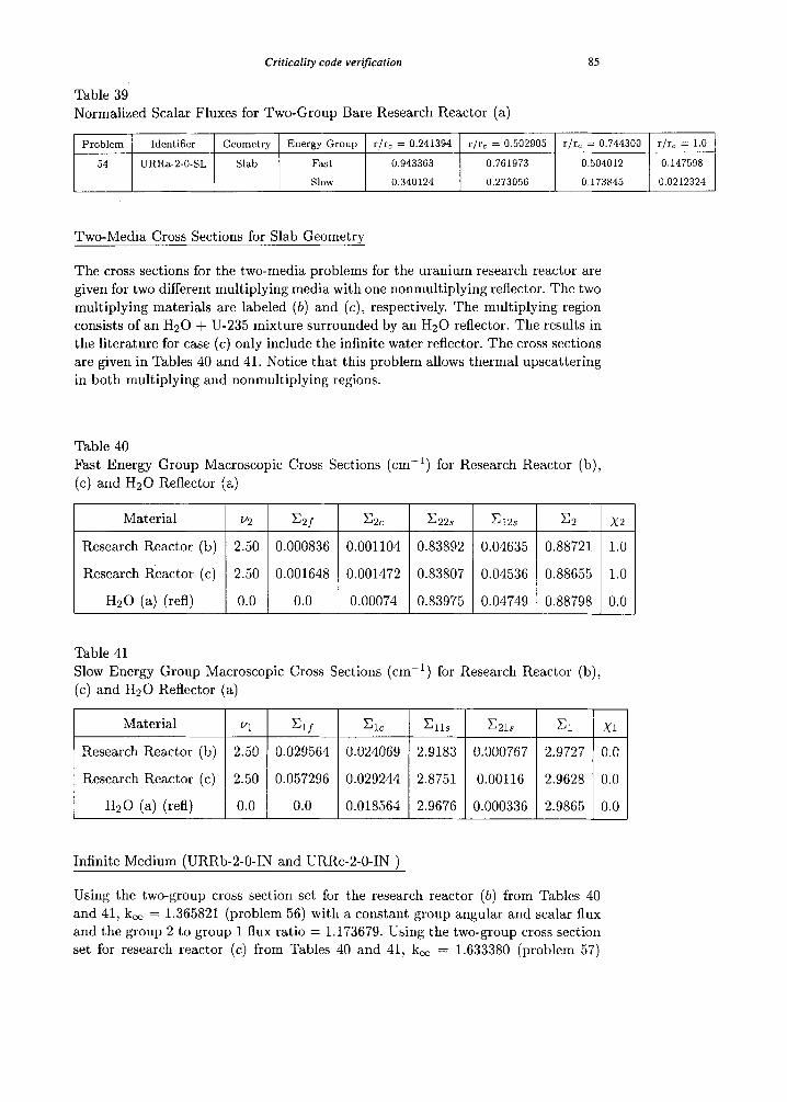
Criticality code verification 85
Table 39 Normalized Scalar Fluxes for Two-Group Bare Research Reactor (a)
Problem Identifier Geometry Energy Group r/r= = 0.241394 r/r= = 0.502905 r/rc = 0.744300 r/r= = 1.0
54 URRa-2-0-SL Slab Fast 0.943363 0.761973 0.504012 0.147598
SlOW 0.340124 0.273056 0.173845 0.0212324
Two-Media Cross Sections for Slab Geometry
The cross sections for the two-media problems for the uranium research reactor are given for two different multiplying media with one nonmultiplying reflector. The two multiplying materials are labeled (b) and (c), respectively. The multiplying region
consists of an Hz0 + U-235 mixture surrounded by an Hz0 reflector. The results in the literature for case (c) only include the infinite water reflector. The cross sections are given in Tables 40 and 41. Notice that this problem allows thermal upscattering in both multiplying and nonmultiplying regions.
Table 40 Fast Energy Group Macroscopic Cross Sections (cm-‘) for Research Reactor (b), (c) and Hz0 Reflector (a)
Material v2 =2f CPC
Research Reactor (b) 2.50 0.000836 0.001104
Research Reactor (c) 2.50 0.001648 0.001472
Hz0 (a) (refl) 0.0 0.0 0.00074
c22s c12s x2 x2
0.83892 0.04635 0.88721 1.0
0.83807 0.04536 0.88655 1.0
0.83975 0.04749 0.88798 0.0
Table 41 Slow Energy Group Macroscopic Cross Sections (cm-‘) for Research Reactor (b), (c) and Hz0 Reflector (a)
Material *1 c1J Cl, CllS
Research Reactor (b) 2.50 0.029564 0.024069 2.9183
Research Reactor (c) 2.50 0.057296 0.029244 2.8751
H20 (a) (refl) 0.0 0.0 0.018564 2.9676
Infinite Medium (URRb-2-O-IN and URRc-2-O-IN )
c21s Cl Xl
0.000767 2.9727 0.0 ml 0.00116 2.9628 0.0
0.000336 2.9865 0.0
Using the two-group cross section set for the research reactor (0) from Tables 40 and 41, k, = 1.365821 (problem 56) with a constant group angular and scalar flux and the group 2 to group 1 flux ratio = 1.173679. Using the two-group cross section set for research reactor (c) from Tables 40 and 41, k, = 1.633380 (problem 57)
86 A. Sood et al.
with a constant group angular and scalar flux and the group 2 to group 1 flux ratio
= 1.933422.
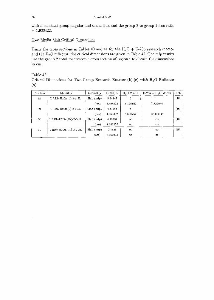
Two-Media Slab Critical Dimensions
Using the cross sections in Tables 40 and 41 for the Hz0 + U-235 research reactor
and the Hz0 reflector, the critical dimensions are given in Table 42. The mfp results
use the group 2 total macroscopic cross section of region i to obtain the dimensions
in cm.
Table 42
Critical Dimensions for Two-Group Research Reactor (b),(c) with Hz0 Reflector
(a)
Problem Identifier Geometry u-235, rc Hz0 Width U-235 + Hz0 Width Ref.
58 URRb-H20a(l)-2.0-SL Slab (mfp) 5.94147 1 [461
(cm) 6.696802 1.126152 7.822954
59 URRb-H20a(5)-2-0.SL Slab (mfp) 4.31485 5 [461
(cm) 4.863392 5.630757 10.494149
60 URRb-H20a(IK)-2.0-SL Slab (mfp) 4.15767 co DC) 1461
(cm) 4.686230 cc 00
61 URRc-H20a(IA-)-2-0-SL Slab (mfp) 2.1826 00 cc [461
(cm) 2.461903 cx Do
Criticality code verification 87
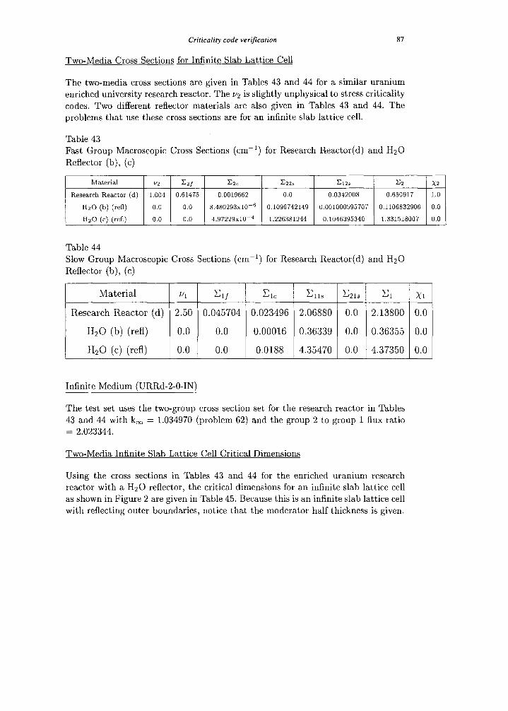
Two-Media Cross Sections for Infinite Slab Lattice Cell
The two-media cross sections are given in Tables 43 and 44 for a similar uranium
enriched university research reactor. The ~2 is slightly unphysical to stress criticality
codes. Two different reflector materials are also given in Tables 43 and 44. The
problems that use these cross sections are for an infinite slab lattice cell.
Table 43 Fast Group Macroscopic Cross Sections (cm-‘) for Research Reactor(d) and Hz0
Reflector (b), (c)
Material 0 CZf czc &zs Cl23 x2 x2
Research Reactor (d) 1.004 0.61475 0.0019662 0.0 0.0342008 0.650917 1.0
Hz0 (b) (refl) 0.0 0.0 8.480293x10⁻⁶ 0.1096742149 0.001000595707 0.1106832906 0.0
Hz0 (c) (red) 0.0 0.0 4.97229x10⁻⁴ 1.226381244 0.1046395340 1.331518007 0.0
Table 44
Slow Group Macroscopic Cross Sections (cm-‘) for Research Reactor(d) and Hz0
Reflector (b), (c)
Material Ul =Lf Cl, c 11s c21s Cl Xl
Research Reactor (d) 2.50 0.045704 0.023496 2.06880 0.0 2;13800 0.0
Hz0 (b) (refl) 0.0 0.0 0.00016 0.36339 0.0 0.36355 0.0
Hz0 (c) (refl) 0.0 0.0 0.0188 4.35470 0.0 4.37350 0.0
Infinite Medium (URRd-2-O-IN)
The test set uses the two-group cross section set for the research reactor in Tables
43 and 44 with k, = 1.034970 (problem 62) and the group 2 to group 1 flux ratio
= 2.023344.
Two-Media Infinite Slab Lattice Cell Critical Dimensions
Using the cross sections in Tables 43 and 44 for the enriched uranium research
reactor with a Hz0 reflector, the critical dimensions for an infinite slab lattice cell
as shown in Figure 2 are given in Table 45. Because this is an infinite slab lattice cell
with reflecting outer boundaries, notice that the moderator half thickness is given.
88 A. Sood et al.
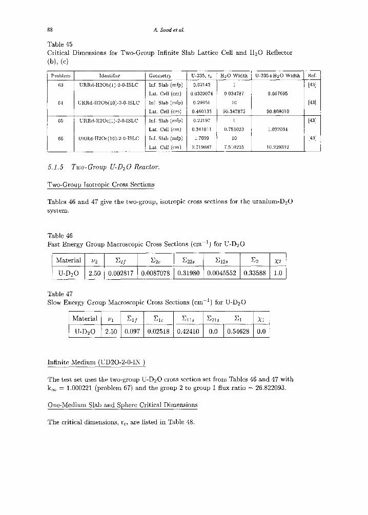
Table 45 Critical Dimensions for Two-Group Infinite Slab Lattice Cell and Hz0 Reflector
(b), (c)
1 Problem 1 Identifier / Geometry
63
64
URRd-HZOb(l)-2-0-ISLC Inf. Slab (mfp)
Lat. Cell (cm)
URRd-HZOb(lO)-P-0-ISLC Inf. Slab (mfp)
Lat. Cell (cm)
U-235, rc H20 Width U-235+HzO Width Ref.
0.02142 1 [431
0.0329074 9.034787 9.067695
0.29951 10 [431
0.460135 90.347875 90.808010
0.22197 1 [431
0.341011 0.751023 1.092034
1.7699 10 1431
2.719087 7.510225 10.229312
5.1.5 Two-Group U-D20 Reactor.
Two-Group Isotropic Cross Sections
Tables 46 and 47 give the two-group, isotropic cross sections for the uranium-D20
system.
Table 46 Fast Energy Group Macroscopic Cross Sections (cm-l) for U-D20
Material u2 =2f c2c c22s &2S x2 x2
U-D20 2.50 0.002817 0.0087078 0.31980 0.0045552 0.33588 1.0
Table 47 Slow Energy Group Macroscopic Cross Sections (cm-‘) for U-D20
Material zq =lf Cl, Ells c21s Cl Xl
U-D20 2.50 0.097 0.02518 0.42410 0.0 0.54628 0.0
Infinite Medium (UD20-2-O-IN j
The test set uses the two-group U-D20 cross section set from Tables 46 and 47 with k, = 1.000221 (problem 67) and the group 2 to group 1 flux ratio = 26.822093.
One-Medium Slab and Sphere Critical Dimensions
. . . The critical dimensions, rc, are listed in Table 48.
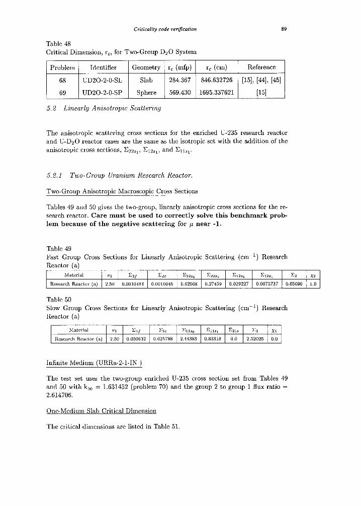
Criticality code verification 89
Table 48 Critical Dimension, rc, for Two-Group DzO System
Problem Identifier Geometry r, (mfp) rc (cm) Reference
68 UD20-2-O-SL Slab 284.367 846.632726 [15], [44], [45]
69 UD20-2-O-SP Sphere 569.430 1695.337621 [151
5.2 Linearly Anisotropic Scattering
The anisotropic scattering cross sections for the enriched U-235 research reactor and U-D20 reactor cases are the same as the isotropic set with the addition of the anisotropic cross sections, C~2~r, CILIA, and Ciisl.
5.2.1 Two- Group Uranium Research Reactor.
Two-Group Anisotropic Macroscopic Cross Sections
Tables 49 and 50 gives the two-group, linearly anisotropic cross sections for the re- search reactor. Care must be used to correctly solve this benchmark prob- lem because of the negative scattering for p near -1.
Table 49 Fast Group Cross Sections for Linearly Anisotropic Scattering (cm-i) Research Reactor (a)
Material m CZf czc czzso czzs, ~12S0 Gzs, x2 x2
Research Reactor (a) 2.50 0.0010484 0.0010046 0.62568 0.27459 0.029227 0.0075737 0.65696 1.0
Table 50 Slow Group Cross Sections for Linearly Anisotropic Scattering (cm-‘) Research Reactor (a)
Material VI Clf Cl, Glso Cll*, CZls Cl Xl
Research Reactor (a) 2.50 0.050632 0.025788 2.44383 0.83318 0.0 2.52025 0.0
Infinite Medium (URRa-2-l-IN )
The test set uses the two-group enriched U-235 cross section set from Tables 49 and 50 with k, = 1.631452 (problem 70) and the group 2 to group 1 flux ratio = 2.614706.
One-Medium Slab Critical Dimension
The critical dimensions are listed in Table 51.
90 A. Sood et al.
Table 51 Critical Dimension, r,, for Two-Group Linearly Anisotropic Scattering Research
Reactor (a)
Problem Identifier Geometry r, (mfp) r, (cm) Reference
71 URRa-2-l-SL Slab 6.2384 9.4959 [341
One-Medium Slab Scalar Neutron Fluxes
Table 52 gives the normalized scalar neutron flux for the two-group bare research
reactor (a) with linearly anisotropic scattering at four spatial points.[32] All values
are normalized with the fast group flux at the center.
Table 52
Normalized Scalar Fluxes for Two-Group Bare Research Reactor (a)
Problem Identifier Geometry Energy Group r/rc = 0.20 r/r= = 0.50 rfrc = 0.80 r/rc = 1.0
71 URRa-2.1.SL Slab Fast 0.963873 0.781389 0.472787 0.189578
SIOW 0.349006 0.280870 0.157376 0.0277639
5.2.2 Two-Group U-D2 0 Reactor.
Two-Group Anisotropic Macroscopic Cross Sections
Tables 53 and 54 gives the two-group, linearly anisotropic cross sections for the
U-D20 system.
Table 53 Fast Energy Group Cross Sections for Linearly Anisotropic Scattering (cm-‘) for
U-D20
Material “2 CZf czc c22so czzs, C12su Qzs, x2 x2
DzO 1 2.50 0.0028172 1 0.0087078 1 0.31980 1 0.06694 1 0.004555 1 -0.0003972 1 0.33588 1 1.0
Table 54
Slow Energy Group Cross Sections for Linearly Anisotropic Scattering (cm-l) for
U-D20
Material VI Clf Cl, Cll,, Gls, z!ls Cl X1
DzO 2.50 0.097 0.02518 0.42410 0.05439 0.0 0.54628 0.0
Infinite Medium fUD20-2-l-IN 1
The test set uses the two-group linearly anisotropic D20 cross section set from Tables 53 and 54 with k, = 1.000227 (problem 72) and the group 2 to group 1 flux
Criticality code verification
ratio = 26.823271.
91
One-Medium Slab Critical Dimension
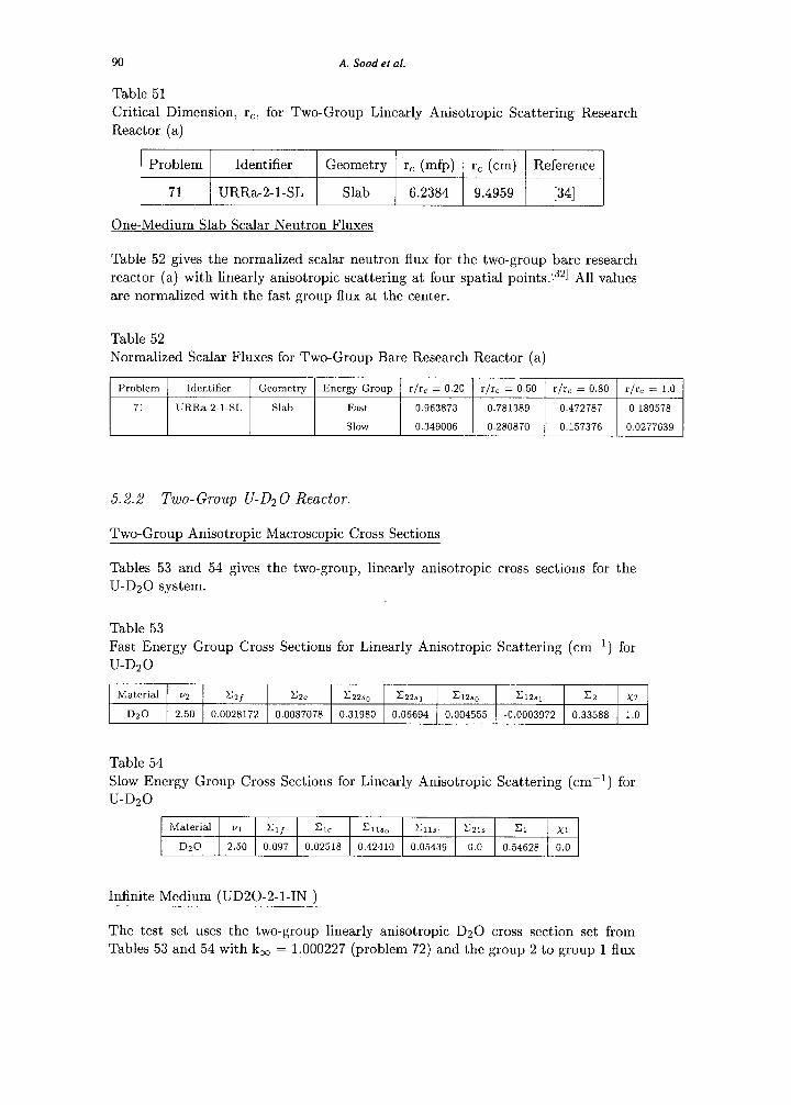
. . . The critical dimension, rc, is listed in Table 55.
Table 55 Critical Dimension, rc, for Two-Group Linearly Anisotropic Scattering for U-D20 Reactor
Problem Identifier Geometry r, (mfp) rc (cm) Reference
73 UD20-2-l-SL Slab 312.18 929.45 1341
6 Three-Energy Group Problem Definitions and Results
A three-energy group isotropic infinite medium problem is defined in this section. The derivation appears in Appendix A.[471J531 This problem assumes no thermal upscattering and no fission neutrons born in the slowest energy group.
The fast energy group is group 3 to be consistent with most of the references. Again, this notation is the reverse of most nuclear engineering textbooks.
The cross sections listed here are similar to the uranium university research reactors. Again, this problem uses cross sections that are reasonable representations of the materials described and are not general purpose values. The cross sections are intended to be used to verify algorithm performance and not to predict criticality experiments. The cross sections are from [47] and are derived in Appendix A.
Infinite Medium (URR-3-O-IN )
Using the three-group cross section set from Tables 56, 57, and 58, k, = 1.600000 (problem 74) with a constant group angular and scalar flux and the group 2 to group 3 flux ratio = 0.480, the group 1 to group 2 flux ratio = 0.3125, and the group 1 to group 3 flux ratio = 0.150.
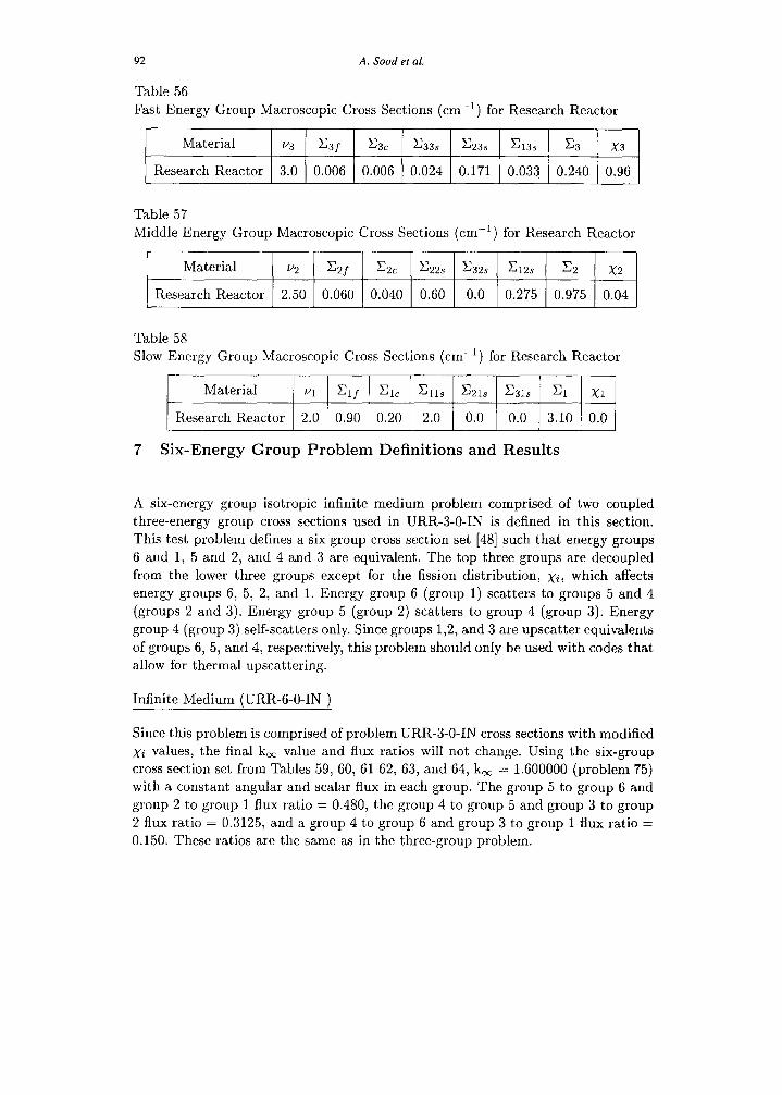
92 A. Sood et al.
Table 56
Fast Energy Group Macroscopic Cross Sections (cm-‘) for Research Reactor
Material v3 C3f c3c c33s c23s c13s x3 x3
Research Reactor 3.0 0.006 0.006 0.024 0.171 0.033 0.240 0.96
Table 57
Middle Energy Group Macroscopic Cross Sections (cm-l) for Research Reactor
Material v2 C2f c2c c22s c32s Q2s x2 x2
Research Reactor 2.50 0.060 0.040 0.60 0.0 0.275 0.975 0.04
Table 58
Slow Energy Group Macroscopic Cross Sections (CIII-l) for Research Reactor
Material Ul Qf Cl, &ls c21s c31s Cl Xl
Research Reactor 2.0 0.90 0.20 2.0 0.0 0.0 3.10 0.0
7 Six-Energy Group Problem Definitions and Results
A six-energy group isotropic infinite medium problem comprised of two coupled
three-energy group cross sections used in URR-3-O-IN is defined in this section. This test problem defines a six group cross section set [48] such that energy groups
6 and 1, 5 and 2, and 4 and 3 are equivalent. The top three groups are decoupled
from the lower three groups except for the fission distribution, xi, which affects
energy groups 6, 5, 2, and 1. Energy group 6 (group 1) scatters to groups 5 and 4
(groups 2 and 3). E nergy group 5 (group 2) scatters to group 4 (group 3). Energy
group 4 (group 3) self-scatters only. Since groups 1,2, and 3 are upscatter equivalents
of groups 6, 5, and 4, respectively, this problem should only be used with codes that
allow for thermal upscattering.
Infinite Medium (URR-6-O-IN j
Since this problem is comprised of problem URR-3-O-IN cross sections with modified
xi values, the final k, value and flux ratios will not change. Using the six-group
cross section set from Tables 59, 60, 61 62, 63, and 64, k, = 1.600000 (problem 75)
with a constant angular and scalar flux in each group. The group 5 to group 6 and
group 2 to group 1 flux ratio = 0.480, the group 4 to group 5 and group 3 to group 2 flux ratio = 0.3125, and a group 4 to group 6 and group 3 to group 1 Aux ratio = 0.150. These ratios are the same as in the three-group problem.
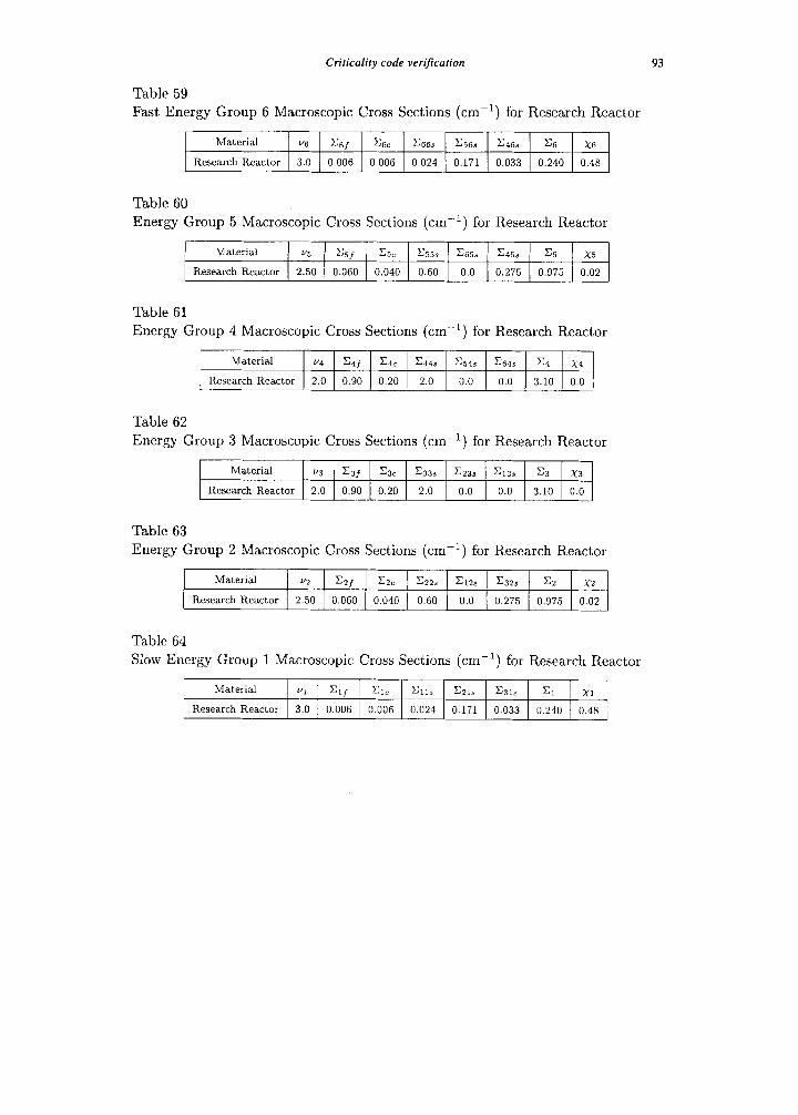
Criticality code veri’carion 93
Table 59 Fast Energy Group 6 Macroscopic Cross Sections (cm-‘) for Research Reactor
Material V6 % &C C66s x568 X4& x6 X6
Research Reactor 3.0 0.006 0.006 0.024 0.171 0.033 0.240 0.48
Table 60 Energy Group 5 Macroscopic Cross Sections (CXK~) for Research Reactor
Material u3 =3/ c5c .Gss c65s G5s x5 X5
Research Reactor 2.50 0.060 0.040 0.60 0.0 0.275 0.975 0.02
Table 61 Energy Group 4 Macroscopic Cross Sections (cm-‘) for Research Reactor
Material v4 C4f & c44s X348 &4s x4 x4
Research Reactor 2.0 0.90 0.20 2.0 0.0 0.0 3.10 0.0
Table 62 Energy Group 3 Macroscopic Cross Sections (cm-‘) for Research Reactor
Material u3 C3f c3c c33s c23s G3s x3 x3
Research Reactor 2.0 0.90 0.20 2.0 0.0 0.0 3.10 0.0
Table 63 Energy Group 2 Macroscopic Cross Sections (cnl-‘) for Research Reactor
Material v? =zf &c c22s ClZs c32s Et X2
Research Reactor 2.50 0.060 0.040 0.60 0.0 0.275 0.975 0.02
Table 64 Slow Energy Group 1 Macroscopic Cross Sections (cn-‘) for Research Reactor
Material Vl =lf Cl, Cll, CZl. C31r Cl Xl
Research Reactor 3.0 0.006 0.006 0.024 0.171 0.033 0.240 0.48
94 A. Sood et al.
8 Summary
In this paper, we have documented 75 problem descriptions with precise results
for the critical dimensions, k,J/ eigenvalue, and some eigenfunction (scalar neutron
flux) results for infinite, slab, cylindrical, and spherical geometries for one- and two-
energy group, multiple-media, and both isotropic and linearly anisotropic scattering
using the listed references. We have not given a complete listing of every referenced
result that has been published. Instead, we have included the references that pro-
vide both true transport solutions and enough information to reproduce the results.
Several other references are included for reference completeness. All test set prob-
lems specifications and results are from peer reviewed journals, and have, in many
cases, been solved numerically by more than one analytic method. These calculated
values for k,ff and the scalar neutron flux are believed to be accurate to at least
five decimal places. Criticality codes can be verified using these analytic benchmark
test problems.
9 ACKNOWLEDGMENTS
The authors would like to thank the following people for their role in making this
document as correct and useful as possible: R.E. Alcouffe, R.A. Axford (U of Illi-
nois), G.E. Bosler, F.B. Brown, J.D. Court, B.D. Ganapol (U of Arizona), R.P.
Gardner (NCSU), D.E. Kornreich, E.W. Larsen (U of Michigan), R.C. Little, R.D.
O’Dell, L.M. Petrie (ORNL), A.K. Prirlja (UNM), J.E. Stewart, and P.P. Whalen.
R.D. O’Dell provided the three- and six-group infinite medium problems.
References
Criticality code verification 95
PI
PI
PI
WI
PI
PI
PI
PI
PI
Briesmeister, J.F. “MCNP - A General Purpose Monte Carlo N-Particle
Transport Code,” Version 4B LA-12625-M.
Alcouffe, R.E., Baker, R.S., Brinkley, F.W., Marr, D.R., O’Dell; R.D. and Walters, W.F. “DANTSYS: A Diffusion Accelerated Neutral Particle
Transport Code System,” LA-12969-M, Los Alamos National Laboratory
(1995).
Parsons, D.K., Sood, A., Forster, R.A., and Little, R.C. “An Analytic
Benchmark Test Set for Criticality Code Verificaiton and Its Application to MCNP and DANTSYS” International Conference on Mathematics and Computation, Reactor Physics and Environmental Analysis, Madrid,
Spain (1999).
Parsons, D.K., Sood, A., Forster, R.A., and Little, R.C.“Verification of MCNP and DANTSYS with the Analytic Benchmark Test Set” Sixth International Conference on Nuclear Criticality Safety, Versailles, France
(1999).
Sood, A., Forster, R.A., and Parsons, D.K.“Analytical Benchmark Test
Set for Criticality Code Verification” Sixth International Conference on Nuclear Criticality Safety, Versailles, France (1999).
Sood, A., Forster, R.A., and Parsons, D.K.“Analytical Benchmark Test Set for Criticality Code Verification” LA-13511 (1999).
“IEEE Software Engineering Standards Collection - Spring 1991 Edition” IEEE, Inc (1991).
Zoldi, C.A. “A Numerical and Experimental Study of a Shock-Accelerated Heavy Gas Cylinder” PhD. Thesis, State University of New York, Stony
Brook (2002).
Argonne National Laboratory “Argonne Code Center: Benchmark Problem Book” Mathematics and Computation Division of the American Nuclear Society, ANL-7416 (1968).
[lo] Briggs, J.B. Criticality Safety Benchmark Specification Handbook
NEA/NSC/DOC (95)03 I Volume I.
[ll] Petrie, L.M. LA-12556-C, Proceedings of the First Annual Nuclear Criticality Safety Technology Project. 18 (1992).
[12] Lee, C.E. and C arruthers, L.M. “Comparison of SN Quadrature Methods in Benchmark Criticality Calculations” LA-9751-M!? UC-82 (1983).
96 A. Sood et al.
[13] Case, K.M. and Zweifel, P.F. ‘(Linear Transport Theory,” Addison- Wesley Publ. Co. , Reading, Mass. (1967).
[14] Grandjean, P. and Siewert, C.E. “The FN Method in Neutron Transport Theory. Part II: Applications and Numerical Results” Nucl. Sci. Eng., 69,
161 (1979).
[15] Siewert, C.E. and Thomas, J.R. “On Two-Group Critical Problems in Neutron Transport Theory” Nzxl. Sci. Eng. 94, 264 (1986).
[16] Kornreich, D.E., and Ganapol, B.D. “The Green’s Function Method For Nuclear Engineering Applications” Nucl. Sci. Eng., 126, 293 (1997).
[17] Shuttleworth, T. “The Verification of Monte Carlo Codes in Middle Earth” Proceedings of 8th International Conference on Radiation Shielding, p 1148
(1994).
[18] Gelbard, E.M. and Prael, R.E. “Computation of Standard Deviations in
Eigenvalue Calculations” Prog. Nucl. Energy, 24, 237 (1990).
[19] Duderstadt, J.J, and Hamilton, L.J. “Nuclear Reactor Analysis, ” John
Wiley and Sons, NY (1976).
[20] Atalay, M.A. “The Reflected Slab and Sphere Criticality Problem with Anisotropic Scattering in One-Speed Neutron Transport Theory” Prog.
Nucl. EneTgy, 31, 299 (1997).
[21] Atalay, M.A. “The Critical Slab Problem for Reflecting Boundary
Conditions in One-Speed Neutron Transport Theory” Ann. Nuc~. Energy, 23, 183 (1996).
[22] Dahl, E.B. and Sjostrand, N.G. “Eigenvalue Spectrum of Multiplying Slabs and Spheres for Monoenergetic Neutrons with Anisotropic Scattering” Nucl. Sci. Eng., 69, 114 (1979).
[23] Sahni, D.C. Dahl, E.B., and Sjostrand, N.G. “Real Criticality Eigenvalues of One-Speed Linear Transport Operator” Trans. Th. Stat. Phy, 24, 1295
(1995).
[24] Garis, N.S. ‘LOne-Speed Neutron Transport Eigenvalues for Reflected
Slabs and Spheres” Nucl. Sci. Eng., 107, 343 (1991).
[25] Sahni, D.C. and Sjostrand, N.G. “Critical and Time Eigenvalues in One-
Speed Neutron Transport” Pro,g. Nucl. Energy, 23, 3, 241 (1990).
[26] Sahni, D.C. “S ome New Result’s Pertaining to Criticalit’y and Time Eigenvalues of One-Speed Neutron Transport Equation” Prog. Nucl.
Energy, 30, 3, 305 (1996).
[27] Sjostrand, N.G. “Criticality of Reflected Spherical Reactors For Neutrons
of One-Speed” Pros. Nucl. Energy, 13, 533 (1986).
Criticality code verification 97
[28] Bell, G.I. and Glasstone, S. “Nuclear Reactor Theory,” Van Nostrand
Reinhold Co. (1970).
[29] Burkart; ,4.R., Ishiguro, Y., and Siewert, C.E. “Neutron Transport in Two Dissimilar Media with Anisotropic Scattering,” Nzlcl. Sci. Eng., 61,
72 (1976).
[30] Burkart, A. R. “The Application of Invariance Principles to Critical
Problems in Reflected Reactors” PhD. Thesis North Carolina State
University (1975).
[31] Boffi; V.C., Molinari, V.G. and Spiga, G. “Anisotropy of Scattering and
Fission in Neutron Transport Theory,” Nucl. Sci. Eng., 64, 823 (1977).
[32] Bosler, G.E. “Critical Slab Solution to the Two-Group Neutron Transport
Equation for Linearly Anisotropic Scattering” PhD. Thesis University of
Virginia (1972). .
[33] Bosler, G.E. and Metcalf, D.R. “Critical Slab Solution to the Two-Group Neutron Transport Equation for Linearly Anisotropic Scattering” Trans.
Am. Nucl. Sot 15, 913 (1972).
[34] Ishiguro, Y. “Two-Group Neutron-Transport Theory with Linearly
Anisotropic Scattering: Half-Range Orthogonality and Critical Slab Problem” Institute de Ener,gia Atomica, 306 Sao Paulo. Brazil (1973).
[35] Kaper, H.G., Lindeman, 4.J., and Leaf, G.K. ‘LBenchmark Values for the Slab and Sphere Criticality Problem in One-Group Neutron Transport Theory” Nucl. Sci. Eng., 54, 94 (1974).
[36] Westfall, R.M. “Benchmark Solutions for the Infinite Critical Cylinder” Trans. Am. Nucl. Sot., 44, 281 (1983).
[37] Westfall, R.M. and Metcalf, D.R. “Exact Solution of the Transport
Equation for Critical Cylindrical Configurations” Trans. Am. Nucl. Sot.,
15, 266 (1972).
[38] Westfall, R.M. and Metcalf, D.R. “Singular Eigenfunction Solution of the Monoenergetic Neutron Transport Equation for Finite Radially Reflected Critical Cylinders” Nucl. Sci. Eng., 52, 1 (1973).
[39] Lathrop, K.D. and Leonard, A. “Comparisons of Exact and S,v Solutions of the Monoenergetic Critical Equation with Anisotropic Scattering” Nzlcl. Sci. Eng., 22, 115 (1965).
[40] Sanchez, R. and Ganapol, B.D. ‘(Benchmark Values for Monoenergetic Neutron Transport in One-Dimensional Cylindrical Geometry with Linearly Anisotropic Scattering” Nuc~. Sci. Eng.; 64, 61 (1983).
[41] Argonne National Laboratory “Reactor Physics Cocstants” United States
Atomic Ener,gy Commission, ANL-5800 (1963).
98 A. Sood et al.
[42] Stewart, J.E. and Metcalf, D.R. “Monoenergetic Neutron Transport in a Finite Critical Reflected Slab System” Trans. Am. Nucl. Sot., 15, 267
(1972).
[43] Stewart, J.E. “Two-Media Solutions to the Neutron Transport Equation” PhD. Thesis University of Viyg:ginia (1974).
[44] Forster, R.A. and Metcalf, D.R. “Two-Group Transport Solutions to the One-Dimensional Critical Slab Problem” Trans. Am. Nucl. Sot., 12, 637
(1969).
[45] Forster, R.A. “Two-Group Critical Slab Problem” PhD. Thesis University
of Virginia, (1970).
[46] Ishiguro,Y. and Garcia, R.D.M. “Two-Media Problems in Two-Group Neutron Transport Theory” NucE. SC;. Eng., 68, 99 (1978).
[47] O’Dell, R.D. “QA Problem-3 Group k, Calculation” Private
Communication (1998).
[48] O’Dell, R.D. “QA Test 2: Upscatter Convergence” Private
Communication (1998).
[49] Henry, A.F. “Nuclear-Reactor Analysis” MIT Press, Cambridge, MA,
(1975).
[50] Lewis, E.E. and Miller, W.F. “Computational Methods in Neutron Transport,” American Nuclear Society, Inc, La Grange Park, 11 (1993).
[51] Whalen, P.P. Private Communication (1998).
[52] Parsons, D.K. and Nigg, D.W. “Extension of the Analytic Nodal Method
for Four Energy Groups” INEL EGG-PBS-6821 (1985).
[53] Parsons, D.K. and Nigg, D.W. “Extension of the Analytic Nodal Method
for Four Energy Groups” Trans. Am. Nut. Sot. 50, 282 (1985).
[54] Larsen, E.W. Private Communication (1998).
[55] Kornreich, D.E., Private Communication (1998,2001).
Criticality code verijication 99
APPENDIX A Derivation of One-, Two-, and Three-Group k,
To follow the benchmark referenced literature for the multi-group prob- lems, the lowest energy group is group 1. This notation is the reverse from most nuclear engineering textbooks.
I One-Energy Group Infinite Medium km
For an infinite, isotropic, homogeneous medium, the neutron leakage term, Sl. V’IJ = 0, and the angular and scalar neutron flux is constant everywhere. Integrating the one-energy group infinite medium form of the transport equation over angle produces:
where 4 is the scalar neutron flux. The equation can be directly solved for k,.
“Cf km=----- ct. - cs
or, in terms of mean number of secondaries, c:
kcxJ = c [
uqzt (Et - C,)(C, + UCf) I
C.1)
(4
C.3)
II Two-Energy Group Infinite Medium k,
The two-group infinite medium form of the neutron transport equation reduces to:
wJ2 = x2242 + ~2lsdJl + p [VZC2f42 + VlCl/~1] (4 co
Cl41 = .Gls$l + ~12s~2 + p [hClfqh + VZCZf42] C.5) 00
Rearranging the equations in terms of 41 and 42:
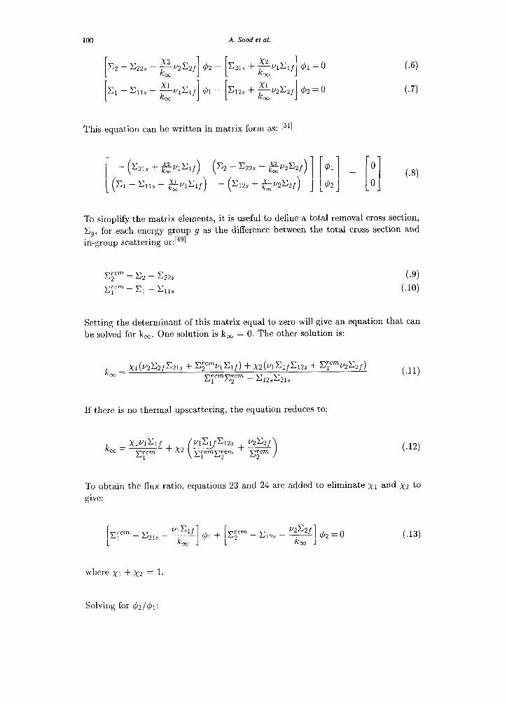
100 A. Sood et al.
i & - x223 - p,czf 1 [ $2 - c21s + +%f 1 41 = 0
00 cc [ Cl - Clls - &@If 1 [ $1 - G2s + FU2C2f 42 = 0 co 1
(4
C.7)
This equation can be written in matrix form as: I511
- c21s + &l&f ( ) (
c2 - c22s - EV2C2f) 41 0
( Cl - Clls - &l&f) - (G2s + 7$y2c2,) Ii1 !I ZZ (4
42 0
To simplify the matrix elements, it is useful to define a total removal cross section,
C,, for each energy group 9 as the difference between the total cross section and
in-group scattering or:F4’l
,ym = c2 - s& (J-J) ,y = Cl - Ells (JO)
Setting the determinant of this matrix equal to zero will give an equation that can
be solved for k,. One solution is k, = 0. The other solution is:
k cm
= Xl(V2C2fC21S + CTwAf) + X2h~lf~12s + qemv2C2f) Tern
=1 qenL - G2J21s C.11)
If there is no thermal upscattering, the equation reduces to:
k = XIUIClf O” CT”” +x2 qemyn + -gG ( nClfCl2s V2C2f
> ( w
To obtain the flux ratio, equations 23 and 24 are added to eliminate x1 and x2 to
give:
[ p-em
1 -C 4&f
21s - ___ kc 1 [ 41 + EyqL - c12s - y$f] qb2 = 0 C.13)
where x1 + x2 = 1.
Solving for &2/&l:
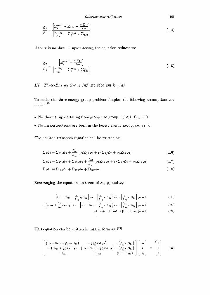
Criticality code verification
If there is no thermal upscattering, the equation reduces to:
101
C.14)
C-15)
III Three-Energy Group In.finite Medium t& (a)
To make the three-energy group problem simpler, the following assumptions are made: 14’1
a No thermal upscattering from group j to group i, j < i, Cij, = 0
l No fission neutrons are born in the lowest energy group, i.e. x1=0
The neutron transport equation can be written as:
x343 = X33&3 + p [V3CSf43 + @z/q52 + V&&1] w
x242 = x22&2 + x23&3 + F [v3x3f43 + V2C2f42 + V&f&]
‘1h = ~llsh + ~12542 + x:3&2
Rearranging the equations in terms of ~$1, 42 and 43:
x3 - c33s - eu3C3f] $3 ~ [El12c2f] $2 - [+lf] $1 = 0
x2 - c23s + --v3c3f $‘3 + x2 ~ c22s -
km 1 1 Eli2C2f] $2 - [+hf] @l = 0
-cl3843 - ~lZs$Z + [Cl - Cll,] 41 = 0
This equation can be written in matrix form as: L4’l
I ‘““( c33s - $53&f) - (gy2Czr) - (emf) @l
X236 + $$V3C3f) (c2 - x22. - +2c24 - (~VIClf) I[ 1 $J2 =
-cl38 -c12c (Cl - Cll,) 43
(3)
(.I71
C.18)
C.19)
C.20)
C.21)
'0
.I
0 (W 0
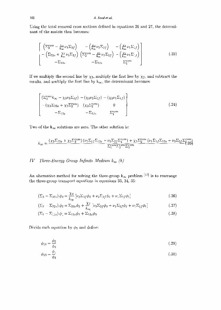
102 A. Sood et al.
Using the total removal cross sections defined in equations 26 and 27, the determi- nant of the matrix then becomes:
-jyem _
3 m fQ3C3J )
- c23s + j53c3J ( )
-c13s
( =jyem _ x2_ c
2 km”2 2J ) (
- e&J )
I
C.23)
-%2s y-em
1
If we multiply the second line by x3, multiply the first line by ~2, and subtract the
results, and multiply the first line by k,, the determinant becomes:
(C;emkm - x3v3c3J) - (X3VZx2J) - (X34lJ)
- (x3x23$ + X2x;em) (X3xsem) 0
-x133 -&2s jy-em
1
C.24)
Two of the k, solutions are zero. The other solution is:
IV Three-Ener.gy Group Injinite Medium km (b)
An alternative method for solving the three-group k, problem [471 is to rearrange
the three-group transport equations in equations 33, 34, 35:
(‘3 - ’33s) 43 = e [v3c3J$3 + V2C2J42 + &$J&l] C.26)
(‘2 - c22S) 42 = x23&3 + e [v3x3J43 + V2C2J42 + vl& J&] C.27)
(Cl - Gls) 41 = C12s&2 + &3s$3 (.W
Divide each equation by 43 and define:
42 $23 = -
43
41 413 = -
43
(.W
t.301
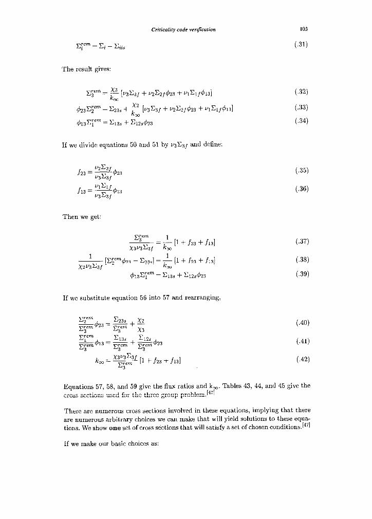
Criticality code verification 103
C.31)
The result gives:
If we divide equations 59 and 51 by v3C3J and define:
f23 = v2Caf -423 U3C3f
f13 = VlClf -413 V3C3f
Then we get:
yem 3
____ = & [1 + f23 + f13] X3V3C3f Co
---& [x$em423 - c23s] = ; [1 + f23 + f131 00
413x;em = &3s + x12&23
t.32)
C.33)
C.34)
C.35)
C.36)
C.37)
C.38)
C.39)
If we substitute equation 56 into 57 and rearranging,
gf)23 zz z + 2 C.46) 3 3
g413 = 2 + $&423 C.41) 3 3 3
k 00 = w [I f f23 + f13] C.42) 3
Equations 57, 58, and 59 give the flux ratios and k,. Tables 43, 44, and 45 give the cross sections used for the three-group problem.[47]
There are numerous cross sections involved in these equations, implying that there are numerous arbitrary choices we can make that will yield solutions to these equa- tions. We show one set of cross sections that will satisfy a set of chosen conditions.[47]
If we make our basic choices as:
104 A. Sood et al.
k, = 1.600
x3=0.96, x2=0.04, x1=0.0
5% of fission production occurs in group 3
20% of fission production occurs in group 2
75% of fission production occurs in group 1
With these choices and the definitions of f23 and frs, we get:
f23=----- = u2c2j 42 4
v3c3 j 43
f13=---- = VlClf 41 15
v3c3 j 43
Using this gives:
Tern x3
- = e [I + f23 + f13] v3c3j
,zern - = 12.0 U3C3j
We can now make more arbitrary choices. If we choose:
l ~3~3.0, C3j=O.OO6
l ~2r2.5, C2j=O.O6O
l u1=2.0, c~j=o.900
Then we get:
423 = 0.480
$13 = 0.150
making E$‘,= 0.216 from equation 63. If we make more choices:
C33S = 0.024
CsC = 0.006
c13s = 0.033
C.43)
C.44)
C.45)
C.46)
C.47)
C-48)
C.49) C.50)
C.51)
Criticality code verification 105
making I&=0.240 and &3,=0.171. Using equation 57, C!jem=0.375. This result now
gives:
C22s = 0.600
czc = 0.040
making X2=0.975
trary choice is:
c IlS = 2.00
C.52)
C.53)
and X12,=0.275. Using equation 58, C;em=l.lO. One last arbi-
C.54)
making X1=3.10 and Cr,=O.20.
V General Multigroup hfinite Medium km
More than three-group k, derivations have been done (see reference [53]). A general
multigroup k, derivation is included in this section for completeness.[54]
Given
where:
5 = GzG matrix
c, = GzG matrix
x = Gzl vector
vCf = 1zG vector
3 = Gzl vector
IC = scalar
C.55)
C.56)
C.57)
C.58)
106 A. Sood et al.
Since uCf 4 is a scalar, it can be cancelled out and we get the followng explicit
result:
C.59)
The right hand side of this equation is a scalar, equal to k. Only one matrix inversion
is necessary.


![Interventional Cardiology - Open Access Journal€¦ · analytical chemistry studying the application of math - ematical and statistical techniques for chemical data analysis [5]](https://img.pdfslide.us/doc/110x75/5f03eaeb7e708231d40b68f6/interventional-cardiology-open-access-journal-analytical-chemistry-studying-the.jpg)


![FUNCTIONAL EQUATIONS IN THE BEHAVIORAL SCIENCES] · 2018-04-04 · Functional equations arise in the sciences because they allow researchers to formulate math- ematical models in](https://img.pdfslide.us/doc/110x75/5e82e8f2a53a852a7f5f48e7/functional-equations-in-the-behavioral-sciences-2018-04-04-functional-equations.jpg)