Embed Size (px)
Citation preview
For the very latest specifications visit www.aeroflex.com
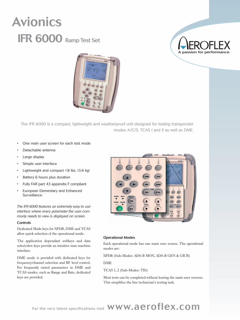
The IFR 6000 is a compact, lightweight and weatherproof unit designed for testing transponder
modes A/C/S, TCAS I and II as well as DME.
AvionicsIFR 6000 Ramp Test Set
• One main user screen for each test mode
• Detachable antenna
• Large display
• Simple user interface
• Lightweight and compact <8 lbs. (3.6 kg)
• Battery 6 hours plus duration
• Fully FAR part 43 appendix F compliant
• European Elementary and EnhancedSurveillance
The IFR 6000 features an extremely easy to useinterface where every parameter the user com-monly needs to view is displayed on screen.
Controls
Dedicated Mode keys for XPDR, DME and TCAS
allow quick selection of the operational mode.
The application dependant softkeys and data
select/slew keys provide an intuitive man machine
interface.
DME mode is provided with dedicated keys for
frequency/channel selection and RF level control.
For frequently varied parameters in DME and
TCAS modes, such as Range and Rate, dedicated
keys are provided.
Operational Modes
Each operational mode has one main user screen. The operational
modes are:
XPDR (Sub-Modes: ADS-B MON, ADS-B GEN & GICB)
DME
TCAS 1, 2 (Sub-Modes: TIS)
Most tests can be completed without leaving the main user screens.
This simplifies the line technician's testing task.
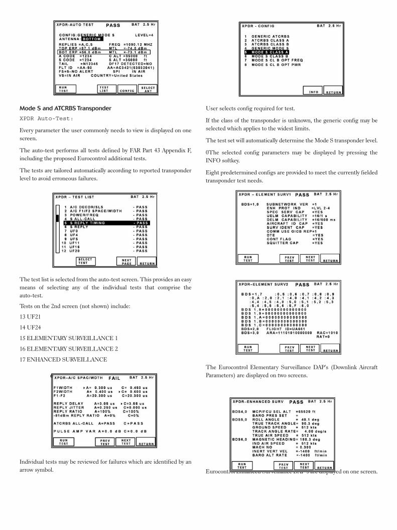
Mode S and ATCRBS Transponder
XPDR Auto-Test:
Every parameter the user commonly needs to view is displayed on one
screen.
The auto-test performs all tests defined by FAR Part 43 Appendix F,
including the proposed Eurocontrol additional tests.
The tests are tailored automatically according to reported transponder
level to avoid erroneous failures.
The test list is selected from the auto-test screen. This provides an easy
means of selecting any of the individual tests that comprise the
auto-test.
Tests on the 2nd screen (not shown) include:
13 UF21
14 UF24
15 ELEMENTARY SURVEILLANCE 1
16 ELEMENTARY SURVEILLANCE 2
17 ENHANCED SURVEILLANCE
Individual tests may be reviewed for failures which are identified by an
arrow symbol.
User selects config required for test.
If the class of the transponder is unknown, the generic config may be
selected which applies to the widest limits.
The test set will automatically determine the Mode S transponder level.
0The selected config parameters may be displayed by pressing the
INFO softkey.
Eight predetermined configs are provided to meet the currently fielded
transponder test needs.
The Eurocontrol Elementary Surveillance DAP's (Downlink Aircraft
Parameters) are displayed on two screens.
Eurocontrol Enhanced Surveillance DAP’s are displayed on one screen.
For the very latest specifications visit www.aeroflex.com
No more HEX data field interpretation!
All Mode S Format tests display parameter in engineering units.
Comprehensive II / SI code and lockout timer test
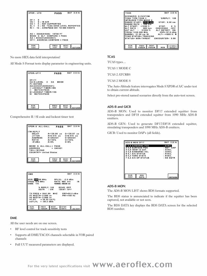
DME
All the user needs are on one screen.
• RF level control for track sensitivity tests
• Supports all DME/TACAN channels selectable in VOR paired
channels
• Full UUT measured parameters are displayed.
TCAS
TCAS types…
TCAS 1 MODE C
TCAS 2 ATCRBS
TCAS 2 MODE S
The Auto-Altitude feature interrogates Mode S XPDR of A/C under testto obtain current altitude.
Select pre-stored named scenarios directly from the auto-test screen.
ADS-B and GICBADS-B MON: Used to monitor DF17 extended squitter fromtransponders and DF18 extended squitter from 1090 MHz ADS-Bemitters.
ADS-B GEN: Used to generate DF17/DF18 extended squitter, simulating transponders and 1090 MHz ADS-B emitters.
GICB: Used to monitor DAP's (all fields).
ADS-B MON:The ADS-B MON LIST shows BDS formats supported.
The BDS status is annunciated to indicate if the squitter has been captured, not available or not seen.
The BDS DATA key displays the BDS DATA screen for the selectedBDS number.
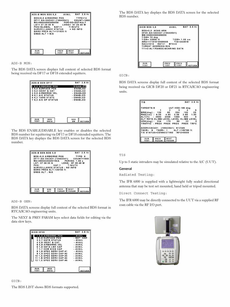
ADS-B MON:
The BDS DATA screen displays full content of selected BDS formatbeing received via DF17 or DF18 extended squitters.
The BDS ENABLE/DISABLE key enables or disables the selectedBDS number for squittering via DF17 or DF18 extended squitters. TheBDS DATA key displays the BDS DATA screen for the selected BDSnumber.
ADS-B GEN:
BDS DATA screens display full content of the selected BDS format inRTCA/ICAO engineering units.
The NEXT & PREV PARAM keys select data fields for editing via thedata slew keys.
GICB:
The BDS LIST shows BDS formats supported.
The BDS DATA key displays the BDS DATA screen for the selectedBDS number.
GICB:
BDS DATA screens display full content of the selected BDS format
being received via GICB DF20 or DF21 in RTCA/ICAO engineering
units.
TIS
Up to 5 static intruders may be simulated relative to the A/C (UUT).
General
Radiated Testing:
The IFR 6000 is supplied with a lightweight fully sealed directional
antenna that may be test set mounted, hand held or tripod mounted.
Direct Connect Testing:
The IFR 6000 may be directly connected to the UUT via a supplied RF
coax cable via the RF I/O port.
For the very latest specifications visit www.aeroflex.com
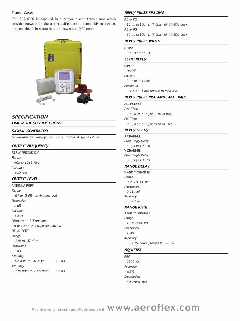
Transit Case:
The IFR-6000 is supplied in a rugged plastic transit case which
provides stowage for the test set, directional antenna, RF coax cable,
antenna shield, breakout box, and power supply/charger.
SPECIFICATIONDME MODE SPECIFICATIONS
SIGNAL GENERATOR
A 5-minute warm-up period is required for all specifications.
OUTPUT FREQUENCY
REPLY FREQUENCY
Range
962 to 1213 MHz
Accuracy
±10 kHz
OUTPUT LEVEL
ANTENNA PORT
Range
-67 to -2 dBm at Antenna port
Resolution
1 dB
Accuracy
±2 dB
Distance to UUT antenna
6 to 300 ft with supplied antenna
RF I/O PORT
Range
-115 to -47 dBm
Resolution
1 dB
Accuracy
-95 dBm to –47 dBm ±1 dB
Accuracy
-115 dBm to <-95 dBm ±2 dB
REPLY PULSE SPACING
P1 to P2
12 μs (±100 ns) (X Channel) @ 50% peak
P1 to P2
30 μs (±100 ns) (Y Channel) @ 50% peak
REPLY PULSE WIDTH
P1/P2
3.5 μs (±0.5 μs)
ECHO REPLY
Control
On/Off
Position
30 nmi (±1 nmi)
Amplitude
-11 dB (±1 dB) relative to reply level
REPLY PULSE RISE AND FALL TIMES
ALL PULSES
Rise Time
2.5 μs (±0.25 μs) (10% to 90%)
Fall Time
2.5 μs (±0.25 μs) (90% to 10%)
REPLY DELAY
X CHANNELFixed Reply Delay
50 μs (±100 ns)
Y CHANNELFixed Reply Delay
56 μs (±100 ns)
RANGE DELAY
X AND Y CHANNELRange
0 to 450.00 nmi
Resolution
0.01 nmi
Accuracy
±0.01 nmi
RANGE RATE
X AND Y CHANNEL
Range
10 to 6500 kts
Resolution
1 kts
Accuracy
±0.01% typical, tested to ±0.5%
SQUITTER
PRF
2700 Hz
Accuracy
±2%
Distribution
Per ARINC 568
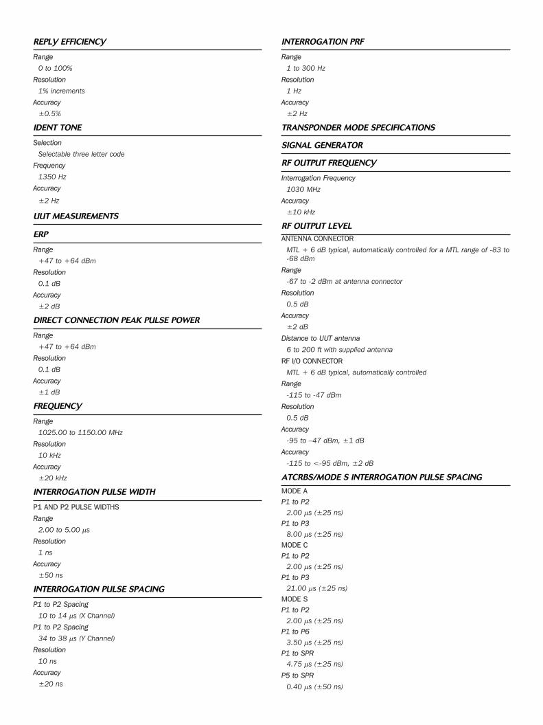
REPLY EFFICIENCY
Range
0 to 100%
Resolution
1% increments
Accuracy
±0.5%
IDENT TONE
Selection
Selectable three letter code
Frequency
1350 Hz
Accuracy
±2 Hz
UUT MEASUREMENTS
ERP
Range
+47 to +64 dBm
Resolution
0.1 dB
Accuracy
±2 dB
DIRECT CONNECTION PEAK PULSE POWER
Range
+47 to +64 dBm
Resolution
0.1 dB
Accuracy
±1 dB
FREQUENCY
Range
1025.00 to 1150.00 MHz
Resolution
10 kHz
Accuracy
±20 kHz
INTERROGATION PULSE WIDTH
P1 AND P2 PULSE WIDTHS
Range
2.00 to 5.00 μs
Resolution
1 ns
Accuracy
±50 ns
INTERROGATION PULSE SPACING
P1 to P2 Spacing
10 to 14 μs (X Channel)
P1 to P2 Spacing
34 to 38 μs (Y Channel)
Resolution
10 ns
Accuracy
±20 ns
INTERROGATION PRF
Range
1 to 300 Hz
Resolution
1 Hz
Accuracy
±2 Hz
TRANSPONDER MODE SPECIFICATIONS
SIGNAL GENERATOR
RF OUTPUT FREQUENCY
Interrogation Frequency
1030 MHz
Accuracy
±10 kHz
RF OUTPUT LEVELANTENNA CONNECTOR
MTL + 6 dB typical, automatically controlled for a MTL range of -83 to
-68 dBm
Range
-67 to -2 dBm at antenna connector
Resolution
0.5 dB
Accuracy
±2 dB
Distance to UUT antenna
6 to 200 ft with supplied antenna
RF I/O CONNECTOR
MTL + 6 dB typical, automatically controlled
Range
-115 to -47 dBm
Resolution
0.5 dB
Accuracy
-95 to –47 dBm, ±1 dB
Accuracy
-115 to <-95 dBm, ±2 dB
ATCRBS/MODE S INTERROGATION PULSE SPACING
MODE AP1 to P2
2.00 μs (±25 ns)
P1 to P3
8.00 μs (±25 ns)
MODE CP1 to P2
2.00 μs (±25 ns)
P1 to P3
21.00 μs (±25 ns)
MODE SP1 to P2
2.00 μs (±25 ns)
P1 to P6
3.50 μs (±25 ns)
P1 to SPR
4.75 μs (±25 ns)
P5 to SPR
0.40 μs (±50 ns)
For the very latest specifications visit www.aeroflex.com
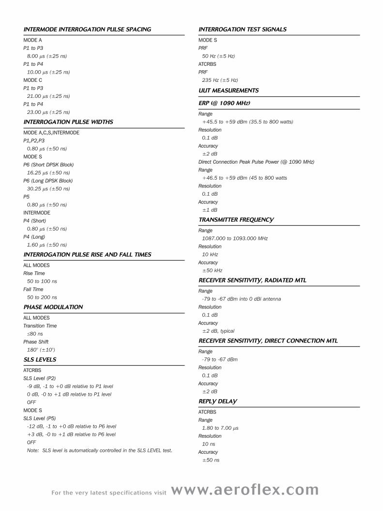
INTERMODE INTERROGATION PULSE SPACING
MODE A
P1 to P3
8.00 μs (±25 ns)
P1 to P4
10.00 μs (±25 ns)
MODE C
P1 to P3
21.00 μs (±25 ns)
P1 to P4
23.00 μs (±25 ns)
INTERROGATION PULSE WIDTHS
MODE A,C,S,INTERMODE
P1,P2,P3
0.80 μs (±50 ns)
MODE S
P6 (Short DPSK Block)
16.25 μs (±50 ns)
P6 (Long DPSK Block)
30.25 μs (±50 ns)
P5
0.80 μs (±50 ns)
INTERMODE
P4 (Short)
0.80 μs (±50 ns)
P4 (Long)
1.60 μs (±50 ns)
INTERROGATION PULSE RISE AND FALL TIMES
ALL MODES
Rise Time
50 to 100 ns
Fall Time
50 to 200 ns
PHASE MODULATION
ALL MODES
Transition Time
≤80 ns
Phase Shift
180° (±10°)
SLS LEVELS
ATCRBS
SLS Level (P2)
-9 dB, -1 to +0 dB relative to P1 level
0 dB, -0 to +1 dB relative to P1 level
OFF
MODE S
SLS Level (P5)
-12 dB, -1 to +0 dB relative to P6 level
+3 dB, -0 to +1 dB relative to P6 level
OFF
Note: SLS level is automatically controlled in the SLS LEVEL test.
INTERROGATION TEST SIGNALS
MODE S
PRF
50 Hz (±5 Hz)
ATCRBS
PRF
235 Hz (±5 Hz)
UUT MEASUREMENTS
ERP (@ 1090 MHZ)
Range
+45.5 to +59 dBm (35.5 to 800 watts)
Resolution
0.1 dB
Accuracy
±2 dB
Direct Connection Peak Pulse Power (@ 1090 MHz)
Range
+46.5 to +59 dBm (45 to 800 watts
Resolution
0.1 dB
Accuracy
±1 dB
TRANSMITTER FREQUENCY
Range
1087.000 to 1093.000 MHz
Resolution
10 kHz
Accuracy
±50 kHz
RECEIVER SENSITIVITY, RADIATED MTL
Range
-79 to -67 dBm into 0 dBi antenna
Resolution
0.1 dB
Accuracy
±2 dB, typical
RECEIVER SENSITIVITY, DIRECT CONNECTION MTL
Range
-79 to -67 dBm
Resolution
0.1 dB
Accuracy
±2 dB
REPLY DELAY
ATCRBS
Range
1.80 to 7.00 μs
Resolution
10 ns
Accuracy
±50 ns
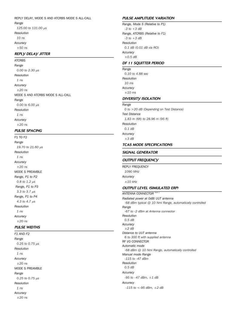
REPLY DELAY, MODE S AND ATCRBS MODE S ALL-CALL
Range
125.00 to 131.00 μs
Resolution
10 ns
Accuracy
±50 ns
REPLY DELAY JITTER
ATCRBS
Range
0.00 to 2.30 μs
Resolution
1 ns
Accuracy
±20 ns
MODE S AND ATCRBS MODE S ALL-CALL
Range
0.00 to 6.00 μs
Resolution
1 ns
Accuracy
±20 ns
PULSE SPACING
F1 TO F2
Range
19.70 to 21.60 μs
Resolution
1 ns
Accuracy
±20 ns
MODE S PREAMBLE
Range, P1 to P2
0.8 to 1.2 μs
Range, P1 to P3
3.3 to 3.7 μs
Range, P1 to P4
4.3 to 4.7 μs
Resolution
1 ns
Accuracy
±20 ns
PULSE WIDTHS
F1 AND F2
Range
0.25 to 0.75 μs
Resolution
1 ns
Accuracy
±20 ns
MODE S PREAMBLE
Range
0.25 to 0.75 μs
Resolution
1 ns
Accuracy
±20 ns
PULSE AMPLITUDE VARIATION
Range, Mode S (Relative to P1)
-3 to +3 dB
Range, ATCRBS (Relative to F1)
-3 to +3 dB
Resolution
0.1 dB (0.01 dB via RCI)
Accuracy
±0.5 dB
DF 11 SQUITTER PERIOD
Range
0.10 to 4.88 sec
Resolution
10 ms
Accuracy
±10 ms
DIVERSITY ISOLATION
Range
0 to >20 dB (Depending on Test Distance)
Test Distance
1.83 m (6ft) to 28.96 m (95 ft)
Resolution
0.1 dB
Accuracy
±3 dB
TCAS MODE SPECIFICATIONS
SIGNAL GENERATOR
OUTPUT FREQUENCY
REPLY FREQUENCY
1090 MHz
Accuracy
±10 kHz
OUTPUT LEVEL (SIMULATED ERP)
ANTENNA CONNECTOR Note 1
Radiated power at 0dBi UUT antenna
-68 dBm typical @ 10 Nmi Range, automatically controlled
Range
-67 to -2 dBm at Antenna connector
Resolution
0.5 dB
Accuracy
±2 dB
Distance to UUT antenna
6 to 300 ft with supplied antenna
RF I/O CONNECTORAutomatic mode
-68 dBm @ 10 Nmi Range, automatically controlled
Manual mode Range
-115 to -47 dBm
Resolution
0.5 dB
Accuracy
-95 to –47 dBm, ±1 dB
Accuracy
-115 to <-95 dBm, ±2 dB
For the very latest specifications visit www.aeroflex.com
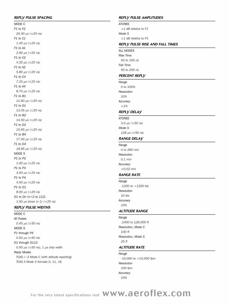
REPLY PULSE SPACING
MODE C
F1 to F2
20.30 μs (±25 ns)
F1 to C1
1.45 μs (±25 ns)
F1 to A1
2.90 μs (±25 ns)
F1 to C2
4.35 μs (±25 ns)
F1 to A2
5.80 μs (±25 ns)
F1 to C4
7.25 μs (±25 ns)
F1 to A4
8.70 μs (±25 ns)
F1 to B1
11.60 μs (±25 ns)
F1 to D1
13.05 μs (±25 ns)
F1 to B2
14.50 μs (±25 ns)
F1 to D2
15.95 μs (±25 ns)
F1 to B4
17.40 μs (±25 ns)
F1 to D4
18.85 μs (±25 ns)
MODE S
P1 to P2
1.00 μs (±25 ns)
P1 to P3
3.50 μs (±25 ns)
P1 to P4
4.50 μs (±25 ns)
P1 to D1
8.00 μs (±25 ns)
D1 to Dn (n=2 to 112)
1.00 μs times (n-1) (±25 ns)
REPLY PULSE WIDTHS
MODE C
All Pulses
0.45 μs (±50 ns)
MODE S
P1 through P4
0.50 μs (±50 ns)
D1 through D112
0.50 μs (±50 ns), 1 μs chip width
Reply Modes
TCAS I / II Mode C (with altitude reporting)
TCAS II Mode S formats 0, 11, 16
REPLY PULSE AMPLITUDES
ATCRBS
±1 dB relative to F1
Mode S
±1 dB relative to P1
REPLY PULSE RISE AND FALL TIMES
ALL MODES
Rise Time
50 to 100 ns
Fall Time
50 to 200 ns
PERCENT REPLY
Range
0 to 100%
Resolution
10%
Accuracy
±1%
REPLY DELAY
ATCRBS
3.0 μs (±50 ns)
Mode S
128 μs (±50 ns)
RANGE DELAY
Range
0 to 260 nmi
Resolution
0.1 nmi
Accuracy
±0.02 nmi
RANGE RATE
Range
-1200 to +1200 kts
Resolution
10 kts
Accuracy
10%
ALTITUDE RANGE
Range
-1000 to 126,000 ft
Resolution, Mode C
100 ft
Resolution, Mode S
25 ft
ALTITUDE RATE
Range
-10,000 to +10,000 fpm
Resolution
100 fpm
Accuracy
10%
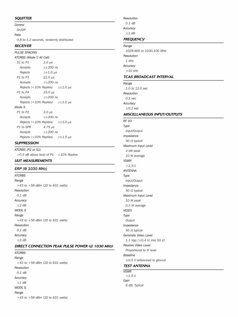
SQUITTER
Control
On/Off
Rate
0.8 to 1.2 seconds, randomly distributed
RECEIVER
PULSE SPACING
ATCRBS (Mode C All Call)
S1 to P1 2.0 μs
Accepts ≤±200 ns
Rejects ≥±1.0 μs
P1 to P3 21.0 μs
Accepts ≤±200 ns
Rejects (<10% Replies) ≥±1.0 μs
P1 to P4 23.0 μs
Accepts ≤±200 ns
Rejects (<10% Replies) ≥±1.0 μs
Mode S
P1 to P2 2.0 μs
Accepts ≤±200 ns
Rejects (<10% Replies) ≥±1.0 μs
P1 to SPR 4.75 μs
Accepts ≤±200 ns
Rejects (<10% Replies) ≥±1.5 μs
SUPPRESSION
ATCRBS (P2 or S1)
>0.5 dB above level of P1 <10% Replies
UUT MEASUREMENTS
ERP (@ 1030 MHZ)
ATCRBS
Range
+43 to +58 dBm (20 to 631 watts)
Resolution
0.1 dB
Accuracy
±2 dB
MODE S
Range
+43 to +58 dBm (20 to 631 watts)
Resolution
0.1 dB
Accuracy
±2 dB
DIRECT CONNECTION PEAK PULSE POWER (@ 1030 MHZ)
ATCRBS
Range
+43 to +58 dBm (20 to 631 watts)
Resolution
0.1 dB
Accuracy
±1 dB
MODE S
Range
+43 to +58 dBm (20 to 631 watts)
Resolution
0.1 dB
Accuracy
±1 dB
FREQUENCY
Range
1029.900 to 1030.100 MHz
Resolution
1 kHz
Accuracy
±10 kHz
TCAS BROADCAST INTERVAL
Range
1.0 to 12.0 sec
Resolution
0.1 sec
Accuracy
±0.2 sec
MISCELLANEOUS INPUT/OUTPUTS
RF I/O
Type
Input/Output
Impedance
50 Ω typical
Maximum Input Level
4 kW peak
10 W average
VSWR
<1.3:1
ANTENNA
Type
Input/Output
Impedance
50 Ω typical
Maximum Input Level
10 W peak
0.5 W average
VIDEO
Type
Output
Impedance
50 Ω typical
Generate Video Level
1.1 Vpp (±0.4 V) into 50 ΩReceive Video Level
Proportional to IF level
Baseline
±0.5 V referenced to ground
TEST ANTENNA
VSWR
<1.5:1
Gain
6 dB, Typical
For the very latest specifications visit www.aeroflex.com
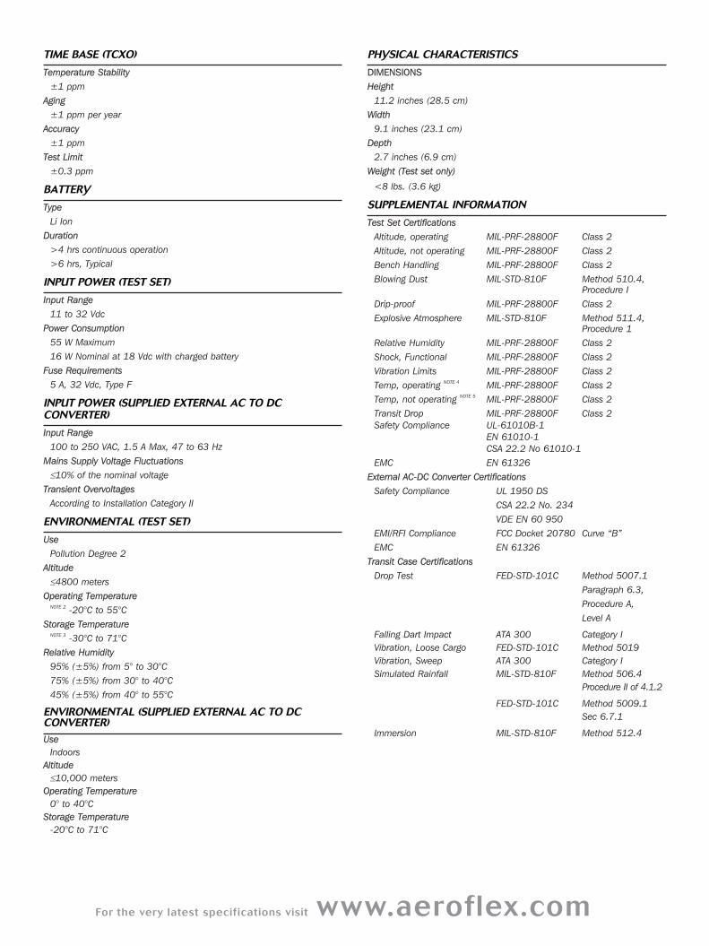
TIME BASE (TCXO)
Temperature Stability
±1 ppm
Aging
±1 ppm per year
Accuracy
±1 ppm
Test Limit
±0.3 ppm
BATTERY
Type
Li Ion
Duration
>4 hrs continuous operation
>6 hrs, Typical
INPUT POWER (TEST SET)
Input Range
11 to 32 Vdc
Power Consumption
55 W Maximum
16 W Nominal at 18 Vdc with charged battery
Fuse Requirements
5 A, 32 Vdc, Type F
INPUT POWER (SUPPLIED EXTERNAL AC TO DCCONVERTER)
Input Range
100 to 250 VAC, 1.5 A Max, 47 to 63 Hz
Mains Supply Voltage Fluctuations
≤10% of the nominal voltage
Transient Overvoltages
According to Installation Category II
ENVIRONMENTAL (TEST SET)
Use
Pollution Degree 2
Altitude
≤4800 meters
Operating TemperatureNOTE 2
-20°C to 55°C
Storage TemperatureNOTE 3
-30°C to 71°C
Relative Humidity
95% (±5%) from 5° to 30°C
75% (±5%) from 30° to 40°C
45% (±5%) from 40° to 55°C
ENVIRONMENTAL (SUPPLIED EXTERNAL AC TO DCCONVERTER)
Use
Indoors
Altitude
≤10,000 meters
Operating Temperature
0° to 40°C
Storage Temperature
-20°C to 71°C
PHYSICAL CHARACTERISTICS
DIMENSIONSHeight
11.2 inches (28.5 cm)
Width
9.1 inches (23.1 cm)
Depth
2.7 inches (6.9 cm)
Weight (Test set only)
<8 lbs. (3.6 kg)
SUPPLEMENTAL INFORMATION
Test Set Certifications
Altitude, operating MIL-PRF-28800F Class 2
Altitude, not operating MIL-PRF-28800F Class 2
Bench Handling MIL-PRF-28800F Class 2
Blowing Dust MIL-STD-810F Method 510.4,
Procedure I
Drip-proof MIL-PRF-28800F Class 2
Explosive Atmosphere MIL-STD-810F Method 511.4,
Procedure 1
Relative Humidity MIL-PRF-28800F Class 2
Shock, Functional MIL-PRF-28800F Class 2
Vibration Limits MIL-PRF-28800F Class 2
Temp, operating NOTE 4
MIL-PRF-28800F Class 2
Temp, not operating NOTE 5
MIL-PRF-28800F Class 2
Transit Drop MIL-PRF-28800F Class 2
Safety Compliance UL-61010B-1
EN 61010-1
CSA 22.2 No 61010-1
EMC EN 61326
External AC-DC Converter Certifications
Safety Compliance UL 1950 DS
CSA 22.2 No. 234
VDE EN 60 950
EMI/RFI Compliance FCC Docket 20780 Curve “B”
EMC EN 61326
Transit Case Certifications
Drop Test FED-STD-101C Method 5007.1
Paragraph 6.3,
Procedure A,
Level A
Falling Dart Impact ATA 300 Category I
Vibration, Loose Cargo FED-STD-101C Method 5019
Vibration, Sweep ATA 300 Category I
Simulated Rainfall MIL-STD-810F Method 506.4
Procedure II of 4.1.2
FED-STD-101C Method 5009.1
Sec 6.7.1
Immersion MIL-STD-810F Method 512.4
Part No. 46891/184, Issue 11, 04/11
CHINA BeijingTel: [+86] (10) 6539 1166Fax: [+86] (10) 6539 1778
CHINA ShanghaiTel: [+86] (21) 5109 5128Fax: [+86] (21) 5150 6112
CHINA ShenzhenTel: [+86] (755) 3301 9358 Tel: [+86] (755) 3301 9356
FINLANDTel: [+358] (9) 2709 5541Fax: [+358] (9) 804 2441
FRANCETel: [+33] 1 60 79 96 00 Fax: [+33] 1 60 77 69 22
GERMANYTel: [+49] 8131 2926-0 Fax: [+49] 8131 2926-130
HONG KONGTel: [+852] 2832 7988Fax: [+852] 2834 5364
INDIATel: [+91] 80 [4] 115 4501Fax: [+91] 80 [4] 115 4502
JAPANTel: [+81] (3) 3500 5591 Fax: [+81] (3) 3500 5592
KOREA Tel: [+82] (2) 3424 2719Fax: [+82] (2) 3424 8620
SCANDINAVIATel: [+45] 9614 0045 Fax: [+45] 9614 0047
SINGAPORETel: [+65] 6873 0991 Fax: [+65] 6873 0992
UK StevenageTel: [+44] (0) 1438 742200Fax: [+44] (0) 1438 727601Freephone: 0800 282388
USATel: [+1] (316) 522 4981 Fax: [+1] (316) 522 1360Toll Free: 800 835 2352
w w w . a e r o f l e x . c o m
i n f o - t e s t @ a e r o f l e x . c o m
As we are always seeking to improve our products,the information in this document gives only a generalindication of the product capacity, performance andsuitability, none of which shall form part of any con-tract. We reserve the right to make design changeswithout notice. All trademarks are acknowledged. Parent company Aeroflex, Inc. ©Aeroflex 2011.
Our passion for performance is defined by three
attributes represented by these three icons:
solution-minded, performance-driven and customer-focused.
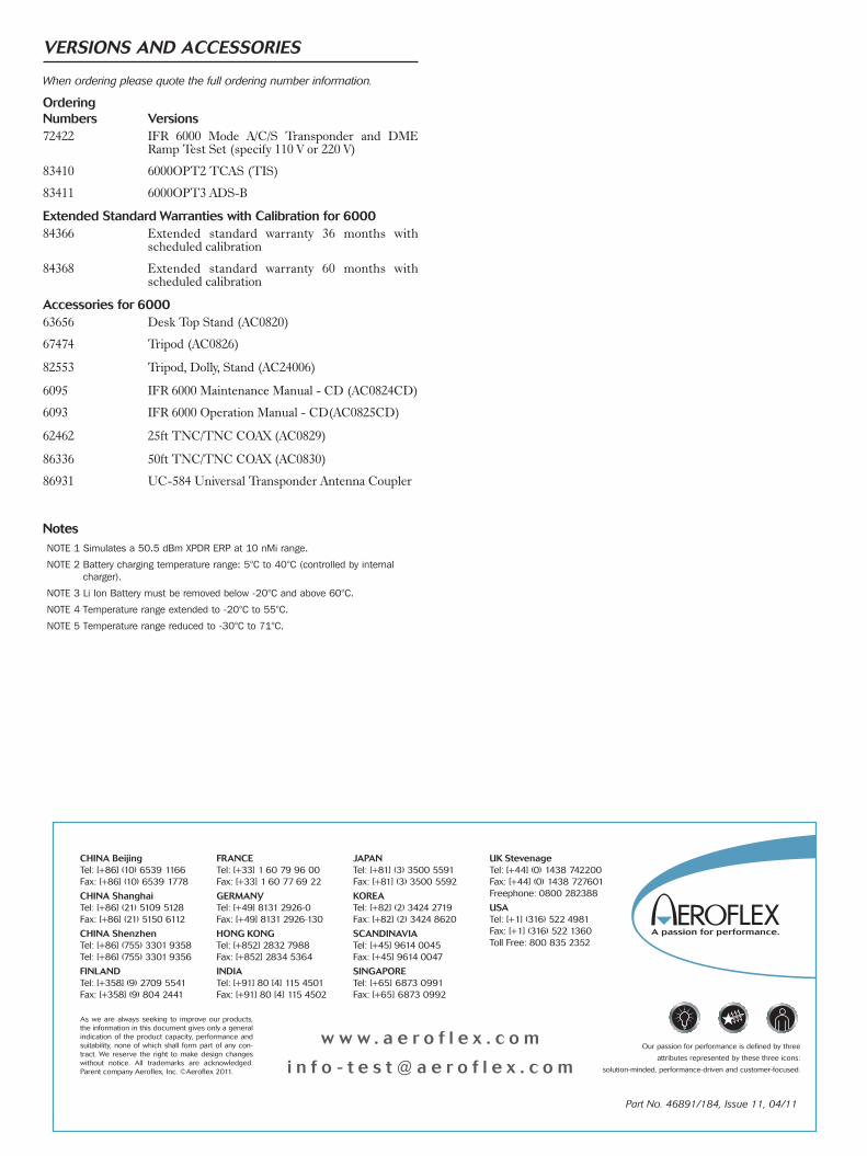
VERSIONS AND ACCESSORIES
When ordering please quote the full ordering number information.
Ordering Numbers Versions72422 IFR 6000 Mode A/C/S Transponder and DME
Ramp Test Set (specify 110 V or 220 V)
83410 6000OPT2 TCAS (TIS)
83411 6000OPT3 ADS-B
Extended Standard Warranties with Calibration for 600084366 Extended standard warranty 36 months with
scheduled calibration
84368 Extended standard warranty 60 months with scheduled calibration
Accessories for 600063656 Desk Top Stand (AC0820)
67474 Tripod (AC0826)
82553 Tripod, Dolly, Stand (AC24006)
6095 IFR 6000 Maintenance Manual - CD (AC0824CD)
6093 IFR 6000 Operation Manual - CD(AC0825CD)
62462 25ft TNC/TNC COAX (AC0829)
86336 50ft TNC/TNC COAX (AC0830)
86931 UC-584 Universal Transponder Antenna Coupler
NotesNOTE 1 Simulates a 50.5 dBm XPDR ERP at 10 nMi range.
NOTE 2 Battery charging temperature range: 5°C to 40°C (controlled by internalcharger).
NOTE 3 Li Ion Battery must be removed below -20°C and above 60°C.
NOTE 4 Temperature range extended to -20°C to 55°C.
NOTE 5 Temperature range reduced to -30°C to 71°C.