Embed Size (px)
Citation preview

FiLe CO
USAAVSCOM TR 90-D-15A
US ARMYAVIATIONSYSTEMS COMMAND
HELICOPTER STRUCTURAL INTEGRITY PROGRAM (HSIP)
Volume I - Structural Test Requirements Specification
J. Martin, J. Fila, and D. Reledorfer
Bell Helicopter Textron Inc.Fort Worth, TX 76101
July 1990
Final Report for Period November 1988 - December 1989
I°I S• ~S EP 13 WO.90
Aprvdfor pblicrlceso; distriuio t51 u 5lso.
Prepared for
AVIATION APPLIED TECHNOLOGY DIRECTORATEUS ARMY AVIATION SYSTEMS COMMANDFZ.PRT EUSTIS, VA 23604-5577
AVIATION APPLIED TECHNOLOGY DIRECTORATE POSITION STATEMENT
This report provides a comprehensive draft structural test requirementsspecification for U.S. Army rotorcraft. The report includes groundtest requirements for metallic and composite airframe and dynamic struc- Itural components applicable to a wide range of rotorcraft and configura-tions (helicopter, tilt rotor, compound, etc.) and missions. The testrequirements defined in this draft specification address safe-life,damage tolerance and total life design methodologies. Special emphasisis placed on establishing and verifying the structural reliabilityof rotorcraft structural components.
This effort is a part of the U.S. Army Aviation System Command's Heli-copter Structural Integrity efforts and will be used as the basis forthe establishment of future Aeronautical Design Standards and Specifica-tions governing structural test requirements of rotorcraft.
Mr. Barry Spigel, Aeronautical Systems and Technology Division, StructuresTechnical Area, served as project engineer for this effort.
DISPOSITION INSTRUCTIONS
D@1tvo tis report by any nethod whiCh redudee recoteruction of the doewment. 0o not return it to theoriginator.
REPORT DOCUMENTATION PAGE Foem Approved
PuU1t rllO0•lt' b•den 9or tt•n £OI'eltf Of ,mtottiitoOf ft d t, o averag tO avefeqO how, " 'IOmO . IiguU•flq tnhte mir foT rvv."W q .lfuCtrUito. wat•hing emusttg data IwIwt.q.Vhrnq end m.,ot~tnlnq th. data f4nltde. and COtmtofeln and P~•i thfq OCI•IC•, Of ,ntfrmiO IM'd Or emotnu r11 rduq tl 1 bu~tde @,t'Matt O~llllf tufly Othe M• 01 t
cOl1e•tOA of infortOhatf. Ifwdttd d q4Jqgi tiOns for fdUC-Ag thCi ISJ'U@I9. tO %vas"ulltOn '•lQ M U SNlf ifV m. 01fIlOtWIoS O for |fIfO tOl t Ow•ia Onm and R90of. 1219 WIegrunnavn Nwghwiw. t•tle 1204. Arl.ngtOn. VA Q& Z10 |)02. and to the 0flce of Manaqenent and Suaqe. PIsowor% Rductioet P101•" (0?07-044 ). W&*Nnon. DC 20103
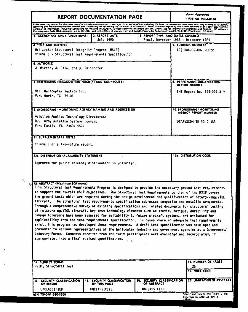
1. AGENCY USE ONLY (Leave blank) 2. REPORT DATE 3. REPORT TYPE AND DATES COVEREDJuly 1990 Final. November 1988 - December 1989
4. TITLE AND SUBTITLE S. FUNDING NUMBERSHelicopter Structural Integrity Program (HSIP) (C) DAAJO2-88-C-0022Volume I - Structural Test Requirements Specification
G. AUTHOR(S)J. Martin, J. Fila, and D. Reisdorfer
"7.FPERFORMING ORGANIZATION NAME(S) AND AODRESS(ES) S. PERFORMING ORGANIZATIONREPORT NUMBER
Bell Helicopter Textron Inc. BHT Report No. 699-099-319Fort Worth, TX 76101
9. SPONSORING/ MONITORINC AGENCY NAME(S) AND ADDRESS(ES) 10. SPONSORING/ MONITORINGAGENCY REPORT NUMBER
Aviation Applied Technology DirectorateU.S. Army Aviation Systems Command USAAVSCOM TR 90-D-15AFo)rt Eustis, VA 23604-5577
11. SUPPLEMENTARY NOTES
Volume I of a two-volune report.
Ila. DISTRIBUTION/AVAILABIUTY STATEMENT 12b. DISTRIBUTION CODE
Approved for public release; distribution is unlimited.
13. ABSTRACT (M~x.rmum 200 words)This Structural Test Requirements Program is designed to provide the necessary ground test requirementsto support the overall HSIP objectives. The Structural Test Requirements portion of the HSIP coversthe ground tests which are required during the design development and qualification of rotary-wing/VTOLaircraft. The structural test requirements specification addresses composite and metallic components.Through a comprehensive survey of existing specifications and related documents for structural testingof rotary-wing/VTOL aircraft, key test technology elements such as static, fatigue, durability anddamage tolerance have been assessed for suitability to future aircraft systems, and evaluated forapplicability into the test requirements specification. In cases where no adequate test requirementsexist, this program has developed those requirements. A draft test specification was developed andpresented to various representatives of the helicopter industry and government agencies at a Government/Industry Forum. Comments received from the forum participants were evaluated and incorporated, ifappropriate, into a final revised specification.
14. SUBJECT TERMS 15. NUMBER OF PAGES
HSIP, Structural Test 2516. PRICE CODE
17. SECURITY CLASSIFICATION 11. SECURITY CLASSIFICATION 1t. SECURITY CLASSIFICATION 20. UMITATION OF ABSTRACTOF REPORT OF THIS PAGE OF ABSTRACT
UNCLASSIFIED UNCLASSIFIED UNCLASSIFIEDNSN 7510-O1-2SO-SO00 Standard Form 298 (Rev 2-89)
Prawrulbd by ANU ,IVtd 1)1.6
TABLE OF CONTENTS
Page
IN T R O D U C T IO N ......... ........................ ......... . .... ..................... 1
I . S C O P E . . . . . . ... . . . . . . . . . . . . . . . . . . . . . . . . . . . . . . . . . . . . . . . . . . . . . . . . . . . . . . . . . . . ... . 2
1.1 T est R equirem ents ............................ ............................... 21.2 G uidance and U sage .......................................................... 21.3 Program Im plem entation ..................................................... 21.4 C lassification of Structure ............................. ...................... 41.5 C ategory of R otorcraft ......................................................... 4
2. APPLICABLE DOCUMENTS ................................................... . 4
3. REQ U IR E M E N TS .. ............................................................... 5
3.1 General Test Requirements ............................................ ....... 5
3 .1.1 D e fin ition s ................ ........... . ..... ....... .. ... ....... ..... . 5
3.1.1.1 Critical Test Conditoin ...................................... 53.1.1.2 Load F actor ................................................ 53.1.1.3 Limit Load or Limit Load Factor3.1.1.4 Ultimate Load or Ultimate Load Factor ....................... 53.1.1.5 Proof Load ............................................. . . 53.1.1.6 Structural Failure - Limit Load Tests ......................... 53.1.1.7 Structural Failure - Ultimate Load Tests ...................... 53.1.1.8 Structural Failure - Repeated Load Tests ..................... 63.1.1.9 Residual Strength ................................. ........ 63.1.1.10 M aterial Variability ........................................ 63.1.1.11 C ritical Part ............................................... 63.1.1.12 Flight Safety Part .......................................... 63.1.1.13 Repeated Loads Tests ....................................... 63.1.1.14 Econom ic Life .............................................. 63.1.1.15 Service L ife ................................. .............. 63.1.1.16 Dam age Tolerance .......................................... 63.1.1.17 D urability ................................................. 63.1.1.18 F atigue .................................................... 73.1.1.19 C oupon .................................................... 73.1.1.20 E lem ent ................................................... 73.1.1.21 Subcom ponent ...................... ...................... 73.1.1.22 C om ponent ................................................ 7
3.1.2 Test O bjectives ... ..... ............................. ................ 7
3.1.2.1 S tatic T est ... ....... ...................................... 73.1.2.2 Repeated Loads Tests ....................................... 73.1.2.3 Elastomeric Materials Tests ................................. 83.1.2.4 Flight Critical Bearings Tests ............................... 8
3.1.3 Design Development and Verification Testing Approachfor New Materials/Processes and Complex Designs ...................... 8
iii
TABLE OF CONTENTS (Continued)
Page
3.1.4 Test Guidelines ................................................. 83.1.4.1 Test Responsibilities ........... ................ ....... 83.1.4.2 Tests Performed by the Government ......................... 83.1_4.3 T est W itnesses ........ ................. ................... 83.1.4.4 Test Docum entation ........................................ 83.1.4.5 A dditional T ests ..................... ...................... 8
3.1.5 Quality Assurance Requirements for Test Programs ................... 8
3.1.5.1 Test Article Conformity .................................... 83.1.5.2 Test Setup Inspection ....................................... 83.1.5.3 Test Instrumentation Inspection ............................ 103.1.5.4 In-Test Inspection ........................................ 103.1.5.5 Post -Test Inspection .... .................. ............... 10
3 .1 .6 . est A rticles ...................... ........... ...................... 10
3.1.6.1 Test Article Configuration ............... .................. 103.1.6.2 Load Application and Component Interaction ............... 103.1.6.3 Replacements and Repairs .................................. 113.1.6.4 Usv of Tested Parts ....................................... 113.1.6.5 Disposition of Test Articles ................................. 113.1.6.6 Use of Static Test Articles for Repeated Loads Tests ........... II
3.1.7 Test Procedures ............................ ........................ 11
3.1.7.1 Test Loads ................................................ 113.1.7.2 Safety Devices ............................................. 123.1.7.3 Prem ature Failure ......................................... 123.1.7.4 Failure A nalysis ........................................... 12
3.1.8 Test Measurements and Instrumentation .............................. 12
3.1.8.1 Test M easurem ents ........................................ 123.1.8.2 Measurement Recording ................................... 123.1.8.3 Test Instrumentation ...................................... 12
3.1.9 Test Article Inspections .............................................. 13
3.1.9.1 Design Inspections ................. ...................... 133.1.9.2 Special Inspections ........................................ 133.1.9.3 Teardown Inspection ............................. ......... 13
3.1 10 Nondestructive Inspection Proof Test .................................. 13
3.2 Airframe Test Requir- ments ........ ................. ........ ........ 13
3.2.1 Airframe Design Development Tests .................................. 14
iv
TABLE OF CONTENTS (Concluded)
Page
3.2.1.1 Elem ent eCoupon Tests ..................................... 143.2.1.2 Element Design Tests ... ................................ 14
3.2.2 Airframe Design Verification Tests .... .............................. 153.2.3 Airframe Qualification Tests.................. .................... 15
3.2.3.1 Proof Tests...................... ...................... 153.2.3.2 Structure Capability Tests .................................. 153.2.3.3 Life Assurance Tests ....................................... 16
3.2.4 Post Q ualification Tests .............................................. 17
3.2.4.1 Surveillance Testing of Parts ............................... 173.2.4.2 Field Repair Qualification Tests ............................ 17
3.3 Dynamic Components (Metallic) Test Requirements ............................ 17
3.3.1 Dynamic Components Design Development Tests ...................... 17
3.3.1.1 CouponlElement Tests ................. ................... 173.3.1.2 ComponerntTests .......................................... 18
3.3.2 Dynamic Components Design Verification Tests ........................ 183.3.3 Tests for Elastomeric Materials ..... ................................. 183.3.4 Dynamic Components Qualification Tests ............................. 18
3.3.4.1 P roof T ests ................................................ 183.3.4.2 Structure Capability Tests .......... ....................... 193.3.4.3 Fatigue, Durability, and Damage Tolerance Tests ............ 203.3.4.4 Tests for Flight Critical Bearings ........................... 21
3.3.5 Past Qualification Tests .............................................. 21
3.4 Dynamic Component (Composite) Test Requirements .......................... 21
3.4.1 Dynamic Components Design Development Tests ...................... 21
3.4.1.1 CouponlElement Tests ..................................... 223.4.1.2 Com ponent Tests .......................................... 22
3.4.2 Dynamic Components Design Verification Tests ..................... 223.4.3 Tests for Elastorneric M aterials ....................................... 2234.4 Dynamic Components Qualification Tests ............................. 23 0
3.4.4.1 P roof T ests ................................................ 233.4.4.2 Structure Capability Tests .................................. 233.4.4.3 Fatigue, Durability, and Damage Tolerance Tests ............ 243.4.4.4 Tests for Flight Critical Bearings ........................... 25
3.4.5 Post Qualification Tests ...................................................... 25 coden
"Nv
INTRODUCTION
This final technical report has been prepared by Bell Helicopter Textron Incorporated (BHTI) for theIlelicopter Structural Integrity Program (HSIP), Structural Test Requirements. This volume con-tains the final revised Structural Test Requirements Specification. Volume II documents the develop-ment of the specification, including supporting rationale
The Army's HSIP will establish a set of formal regulations, standards and specifications to ensure thatstructural integrity receives attention early in the concept definition phase and is an integral part ofthe design, testing, and operation of an aircraft system HSIP will require the development of struc-tural design criteria for Army rotorcraft which define the design requirements and design factors forgiven missions, classes and configurations of the aircraft. Additional specifications will be written todefine the structural requirements for the materials and processes qualification, the analysis and testof the design, and the operational data acquisition and data management requirements for a weaponsystem. Also, a structural integrity verification program will assess the structural integrity specifica-tions and procedures through the design, test, and in-service monitoring of selected helicopter compo-nents.
This Structural Test Requirements Program is designed to provide the necessary ground test require-ments to support the overall HSIP objectives. In general, the Structural Test Requirements portion ofthe HSIP covers the ground tests which are required during the design development and qualificationof rotary-wing/VTOL aircraft. Flight test requirements are not included in this program.
The purpose of the HSIP Structural Test. Requirements Program is to develop a comprehensive Struc-tural Test Requirements Specification for Army rotory-wing/VTOL aircraft. The structural test re-quirements specification addresses composite and metallic airframe components, and composite andmetallic dynamic components separately.
Through a comprehensive survey of existing specifications and related documents for structural test-ing of rotary-wing(VTOL aircraft, key test technology elements such as static, fatigue, durability anddamage tolerance have been assessed for suitability to future aircraft systems, and evaluated for ap-plicability into the test requirements specification. In cases where no adequate test requirements ex-ist, this program has developed those requirements.
A draft test specification was developed and presented to various representatives of the helicopter in-dustry and government agencies at a Government/Industry Forum. Comments received from the fo-rum participants were evaluated and incorporated, if appropriate, into a final revised specification.
L1
HELICOPTER STRUCTURAL INTEGRITY PROGRAM
ROTORCRAFT STRUCTURAL TEST REQUIREMENTS, GROUND
1. SCOPE
1.1 Test Requirements. This document presents a comprehensive set of structural ground test re-quirements for all types of rotary-wingfVSTOL aircraft (rcfereed to hereii as "rotorcraft"). Due to thepotential wide variety of design philosophy, criteria requirements, and configurations, it is not the in-tent of this specification that all of the requirements in Sections 3.2, 3.3, and 3.4 be applicable for ev-ery acquisition program. Specific tests contained herein should be selected that meet the objecL'ives ofthe acquisition program.
1.2 Guidance and Usage. This document is intended to provide guidance for rotorcraft procurementprograms, to serve the procurement agency in the development of specific system specifications, and toserve the contractor ir, developing a viable structural test program. At the program outset, consider-ation should be given by the procuring agency to the need for special additional tests, such as landinggear drop tests, crashworthiness tests (static and dynamic), bird strike tests, pressurization tests, bal-listic damage tests, high energy laser damage tests, and lightning strike protection tests.
The contractor shall prepare an airworthiness qualification specification (AQS) which will identify allof the applicable ground test elements, which are selected from this test requirements specification, inorder to meet the particular objectives of the acquisition program. The AQS will also contain rationaleand basis for selection of the tests in support of the system design criteria. The structural integrity ofthe rotorcraft and its components may be verified by analysis, test, or a combination of test and analy-sis, as proposed by the contractor. The structural integrity program shall verify the ultimate load ca-pability, structural life, and structural reliability of the rotorcraft. Consideration should be given tothe extent of test requirements based upon program elements such as "lead-the-fleet" or "flight safetyparts," redundancy of design, inspection intervals, and fail-safe or safe-life design philosophies. Thecontractor should propose the most economical and schedule-effective approach to the overall structur-al test program as affirmed by substantiating data.
Additional considerations that should be taken into account when selecting the applicable test re-quirements are as follows:
a. Life Assurance Methodologies Approach. Test requirements can only be defined relativeto the approach used for life determination. These approaches will differ for variousstructures and are highly depe, ,dent on material/component failure modes and the antici-pated/verified load spectrum (low, high cycle or both). The contractor shall include thechosen life assurance methodologies into the AQS which describes the proposed methodof repeated loads qualification and the degree of testing and analysis necessary for quali-fying each major component.
b. Reliability. Depending upon the reliability requirements of a specific acquisition pro-gram, the contractor may have to define a reliability methodology to meet those require-ments. The type of tests and number of test articles/specimens need to be selected to sup-port the chosen methodology.
1.3 Progfram Implementation. The determination as to whether or not a particular test method/type isto be utilized is made through a stepwise procedure involving the contracting agency and the contrac-tor, as shown in Figure 1.
2

CONTRACT CONTRACTORAGENCY
MIL7SPECIFICATION
STR TEST RQMTS
TAILOR FOR :TAILOR FORSPECIFIC SPECIFIC
PROGRAM 0PROGRAM~
DRAFT (PROGRAM -
SPECIFIC)INTERIM DOCUMENT
CONTRACTOR
AQS
GOV'TREVIEW &
APPROVAL
APPROVED AQSPROGRAM
TESTDOCUMENT
Fieure 1. Program implementation.
3
1.4 Classification of Structure. Rotorcraft structure is classified as either "airframe" or "dynamic"structure. In general, the dynamic structure includes the rotors, rotor masts, control systems, and thedrive system excluding gears, bearings and interconnecting shafts. The airframe structure includesall other structure. The specific components of these classifications, which include both metallic andnonmetallic structure, are listed in paragraphs 3.2, 3.3, and 3.4.
1.5 Category of Rotorcraft. Rotorcraft are categorized for the purpose of this specification as "trans-port/utility", "observation/scout", "attack", or "trainer". Rotorcraft configurations include, but are notlimited to, single rotor, coaxial rotor, tandem rotor, tilt rotor, tWlt wing, or compound (using turbofans,turboprops, or turbojets as auxiliary power sources).
2. APPLICABLE DOCUMENTS
(Document references will be added by the Army after other specifications related to HSIP have beenidentified and/or formulated.)
4

GENERAL
3, REQUIREMENTS
3.1 General Test Requirements. The following subparagraphs contain general test requirements andapply to all acquisition programs using this document.
3.1.1 Definitions.
3.1.1.1 Critical Test Condition. The design loading condition for which margins of safety indicate thestructure is most likely to fail.
3.1.1.2 Load Factor. The ratio of a given load to a reference load. The reference load is usually theweight of the helicopter or the magnitude of the load when the helicopter is in static equilibrium.When employed, a subscript indicates the direction of the given load.
3.1.1.3 Limit Load or Limit Load Factor. A load or load factor which establishes a strength level fordesign of the rotorcraft and its components and is the maximum load within the flight envelope exper-ienced during the life of the rotorcraft.
3.1.1.4 Ultimate Load or Ultimate Load Factor. The limit load or limit load factor multiplied by an ul-timate factor of safety specified by the structural design criteria or reliability considerations, whichev-er is greater, for the specific acquisition program (normally 1.5).
3.1.1.5 Proof Load. A load that is of less magnitude than that which would induce permanent defor-mation or damage to the structure which is applied to provide test substantiation of strength, rigidity,or functional interference. A percentage of limit load will normally be specified as a minimum to beattained on actual flight hardware prior to rotorcraft first flight, or prior to use on any rotorcraft.
3.1.1.6 Structural Failure - Limit Load Tests. A structural test failure shall be the occurrence of oneor more of the following events in metallic structure:
a. Evidence of yield.
b. Evidence of permanent set. Permanent set is any deformation which remains after re-lease of load.
For composite structures, test failure at limit load shall be the occurrence of one or more of thefollowing events:
a. Evidence of load induced damage (cracks, delaminations, disbonds, etc.) that would detri-mentally affect the structural life of the component.
b. A change (increase or decrease) in structural stiffness in excess of dynamically acceptablelimits. (These limits are determined by flutter or vibration level constraints.)
3.1.1.7 Structural Failure - Ultimate Load Tests. A structural test failure shall be the occurrence of
one or more of the following events in metallic or composite structure:
a. Inability to sustain the applied test load for 3 seconds.
b. Measurement of g:oss area strains which exceed the environmentally and statisticallyreduced gross area design ultimate allowable.
5
3.1.1.8 Structural Failure - Repeated Load Tests. A test failure shall be the occurrence of one or moreof the following events in metallic or composite structure:
a. Inability to sustain the applied test load.
b. Initiation and growth of damage to the size that would not meet the required residualstrength load.
c. A change (increase or decrease) of structural stiffness in excess of dynamically acceptablelimits. (These limits are determined by flutter or vibration level constraints.)
d. Initiation or growth of damage to the extent that would require maintenance action.
3.1.1.9 Residual Strength. This is the remaining load carrying capability of a structural component orassembly that has been subjected to repeated loads testing or of a damaged structural assembly. Forfatigue tests, the required magnitude of the load shall be the maximum load that the structure mightencounter during its lifetime. For damage tolerance tests, the required magnitude of the load is themaximum load that the structure might encounter during a specified inspection interval or during theaircraft's lifetime for non-inspectable structure. For both types of repeated load tests, the required re-sidual load will include compensation for environ.. ental effects if the test is not conducted in the criti-cal environment.
3.1.1.10 Material Variability. The term that refers to the statistical distribution in physical and me-chanical properties due to variations of materials and processes. Material variability must be takeninto account for both composite and metallic materials.
3.1.1.11 Critical Part. A structural part, assembly, installation, or production system with any criti-cal characteristics whose failure would result in an ,-safe condition in the completed product. Unsafecondition is defined as one which could cause loss o. the aircraft or any of its major components, loss ofcontrol, or a condition which could cause injury to occupants of the aircraft or ground support person-nel.
3.1.1.12 Flight Safety Part. Any part, assembly, or installation where failure, malfunction, or ab-sence could cause loss or serious damage to the aircraft and/or serious injury or death to the occupantsor ground support personnel.
3.1.1.13 Repeated Loads Tests. Tests conducted under cyclic loading of a specimen, part, or full-scalecomponent. Fatigue tests, durability tests, and damage tolerance tests are examples of repeated loadstests.
3.1.1.14 Economic Life. The life indicated by the results of the durability test program at which wide-spread damage occurs that is uneconomical to repair and, if not repaired, could cause functional prob-lems affecting operational readiness.
3.1.1.15 Service Life. TLe specified time during which a part, component or aircraft can safely oper-ate.
3.1.1.16 Dan.age Tolerance. The ability of a structure to resist failure due to the presence of flaws,cracks, or other damage for a specified period of unrepaired usage.
3.1.1.17 Durability. The ability of a structure to resist cracking (including stress corrosion and hydro-gen induced cracking), corrosion, thermal degradation, delamination, wear, and the effects of foreignobject damage for a specified period of time.
6
3.1-1.18 Fatizue. The ability of the structure to resist the initiation of damage under repeated loadsfor a specified period of time.
3.1.1.19 Coupon. This is a small test specimen that is used for evaluation of basic material properties
or of properties of generic structural features, such as .'onded or mechanically fastened joints.
3.1.1.20 Element. This is a representation of a more complex structural member, such as a skin,
stringers, shear panels, sandwich panelsJoints, or splices.
3.1.1.21 Subcomponent. This is a major three-dimensional structure which can provide completestructural renresentation of a section of the full structure, such as a stub-box, section of a spar, w:ngpanel, wing rib, body panel or frames.
3.1.1.22 Component. This is a major section of the structure (hub, rotor blade, wing, fin, horizontal
stabilizer) which can be tested as a complete unit to qualify the structure.
3.1.2 Test Objectives.
3.1.2.1 Static Test. Static tests of the airframe structure are conducted on a full scale airframe, majorstructural components, and/or elements. Static tests of dynamic components are conducted on criticalparts.
The objectives of a static test program are to:
a. Verify that the design static strength and structural stiffness meet or exceed the requireddesign loads
b. Substantiate design static strength ana identify failure modes
c. Validate analytical m3thods that are used in substantiating the structure by analysis
3.1.2.2 Repeated Loads Tests. Repeated loads tests of the airframe structure may be conducted on afull scale airframe or on major structural components. Fatigue tests and damage tolerance tests of dy-namic components are conducted on critical parts. Durability tests are conducted on parts wherecracking, delamination, or other structural or material degradation such as wear or corrosion could re-sult in excessive maintenance problems, functional problems affecting operational readiness, or sig-nificant cost impact.
The objectives of a repeated loads test program are to:
a. Locate any test-detectable fatigue or fracture critical areas of the structure not shown bythe design analyses, and identiA", failure modes
b. Verify that the capability uv ucture is not degraded beyond acceptable limits dur-ing its specified service life w 4bjected to the design spectra
c. Provide full scale test data to analytically establish the predicted service life and/or eco-
nomic life of the structure
d. Provide a basis for inspection requirements
e. Provide a ready reference for comparison of test results with service use
7
f. Validate analytical methods to be used in substantiating the structure by analysis
3.1.2.3 Elastomeric Materials Tests. The objective of these tests is to verify that the elastomeric com-ponent is adequate for the intended application.
3-1.2.4 Flight Critical Bearings Tests. The objective of these tests is to verify the life/function of flightcritical bearings.
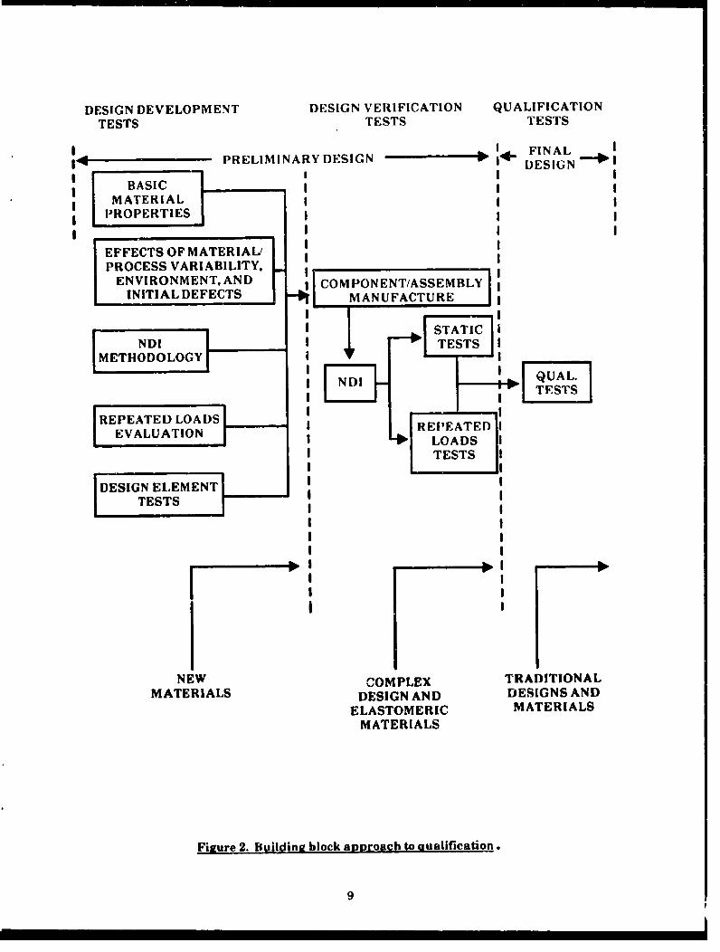
3.1.3 Design Development and Verification Testing Approach for New Materials/Processes and Complex Designs. A building block approach to qualification shall be used for new materials and complexdesign configurations. The new materials are defined as those materials whose properties and designallowables are absent from current specifications. Complex design configurations are those structuresthat cannot be accurately analyzed with confidence or designs without previous service experience.The intent of these tests is to provide information for the component or structure design prior to finalqualification tests, refer to Figure 2.
New materials will be evaluated for material properties, effects of material/process variability, envi-ronment, and defects. Nondestructive inspection methods, repeated load behavior, and component. de-pendent properties will also be determined. This information will be used in determining the initialdesign concept.
Complex designs and new material design concepts will be evaluated for static and/or repeated load ca-pabilities. Results from these subcomponent tests may influence the final design so that qualificationby test and/or analysis may be accomplished in a timely manner.
3.1.4 Test Guidelines
3.1.4.1 Test Responsibilities. In the event any test herein is to be conducted by the Government, thecontract shall so state. Otherwise all tests shall be conducted by the contractor.
3.1.4.2 Tests Performed by the Government. The Government test activity shall be responsible forconducting tests in accordance with the requirements of this specification.
3.1.4.3 Test Witnesses. As specified by the contract, the acquisition activity or local representativeshall be notified to witness the test and certify the test. record.
3.1.4.4 Test Documentation. As specified by the contract, test plans and test reports will be submittedfor approval. All test data shall be retained as specified in the procuring contract.
3.1.4.5 Additional Tests. If the tests to be performed by the contractor, as required by this specifica-tion and/or the contract, are inadequate to prove that the rotorcraft structure meets the specified de-sign requirements, the contractor or the acquisition activity shall propose amendments to the contractto include tests which will prove adequately that the structure meets the specified structural perfor-mance requirements.
3.1.5 Quality Assurance Reauirements for Test Programs
3.1.5.1 Test Article Conformity. Each test article shall be conformed to the applicable engineeringdata, with all deviations reviewed and approved by the customer prior to test.
3.1.5.2 Test Setup Inspection. Each test setup shall be inspected as provided by the approved test planfor test article definition, test article location, test load application points, and test article reactionpoints.
8
DESIGN DEVELOPMENT DESIGN VERIFICATION QUALIFICATION
TESTS TESTS TESTS
___ ___ I FI NA LPRELIMINARY DESIGN DESIGNABASIESCG
MATERIALPROPERTIES
EFFECTS OF MATERIAL/PROCESS VARIABILITY,
ENVIRONMENT, AND COM PONENT/ASSEMBLYINITIAL DEFECTS -I MANUFACTURE
M • STATIC1D TESTS
[METHODOLOGY
INDI
PEATED LOADSPEATEDEVALUATION RP.E I
I* LOADS ITESTS I
DESIGN ELEMENTTESTS
I I
NEW COMPLEX TRADITIONALMATERIALS DESIGN AND DESIGNS AND
ELASTOMERIC MATERIALSMATERIALS
Figure 2. Building block approach to aualification.
9
3.1.5.3 Test Instrumentation Inspection. The test instrumentation shall be inspected for compliancewith the approved test plan for location and orientation prior to the test.
3.1.5.4 In-Test Inspection. Test articles shall be inspected during test as defined in the approved testplan.
3.1.5.5 Post-Test Inspection. Test articles shall be inspected at the completion of scheduled testing inaccordance with the approved test plan.
3.1.6 Test Articles. The contractor shall furnish test articles for performance of the tests. The follow-ing subparagraphs contain requirements which are common to all full scale test articles. To the extentpractical, these requirements also apply to the element and subcomponent tests of paragraphs 3.2, 3.3,and 3.4.
3.1.6.1 Test Article Configuration. The full scale structural ground test articles shail be complete andrepresentative of the flight article structure as follows:
a. Items such as fixed equipment and useful load, and their support structure may be omit-ted from the test structure provided the omission of these parts does not significantly af-fect the load, stress, strength, stiffness, or deflection of the structure to be tested; and pro-vided the omitted parts would not be critically loaded in the test if they were to be in-stalled.
b. All attachment holes for equipment, brackets, etc., and holes for routing of lines andwires, etc.,must be included.
c. Substitute parts or test fixtures may be used provided they reproduce the effects of theparts for which they are substituted, and the structural integrity of the parts for whichsubstitutions are made are demonstrated by supplementary test or analysis.
d. All structural modifications to the test articles that are necessary to accommodate theloading devices shall be designed in such a manner as to assure that the strength and ri-gidity characteristics of the modified structure will be equivalent to those of the actualstructure.
e. Paint or other finishes that do not affect the structural performance (strength, rigidity,fatigue, durability, etc.) may be omitted.
f. Mechanical portions of the flight control systems shali be intact to the extent required tosimulate and introduce or react test loads for the particular test program.
3.1.6.2 Load Aiplication and Commonent Interaction. In a test of a structural component, the actualinteraction between the component being tested and its adjacent components shall be existent or simu-lated. Structural components may be tested in a test fixture and/or loaded by substitute parts suchthat:
a. There is no possibility of interference or deflection that would result in improper loading
of the component under test or adjacent components
b. The primary loads and reactions acting on the test component can be determined
c. All parts of the structure critical for the pertinent design condition can be tested and canbe loaded simultaneously, if practicable.
10

3.1.6.3 Replacements and Repairs. Changes, adjustments, reinforcements, and repairs made in thetest article to meet specified structural performance requirements shall be representative of thosewhich will be incorporated in the flight test articles and production rotorcraft.
3.1.6.4 Use of Tested Parts. Parts of any test article that have been structurally tested shall not beused on any flight vehicle or any ground whirl test article unless specifically approved by the acquisi-tion activity. An exception is made for parts that have been only proof-load tested.
3.1.6.5 Disposition of Test Articles. After completion of the authorized tests, the ground test articlesshall be dispositioned in accordance with instructions issued by the acquisition activity. Prior to re-ceipt of such instructions, ground test articles shall not be intentionally damaged or mutilated.
3.1.6.6 Use of Static Test Articles for Repeated Loads Tests. Static test articles shall not be used dur-ing subsequent fatigue/damage tolerant tests unless it can be shown analytically that the localized ef-fects due to the static test loads do not affect the fatigue/damage tolerant characteristics of the testcomponent.
3.1.7 Test Procedures
3.1.7.1 Test Loads. Initial structural testing shall be conducted using analytically derived designloads. Particular consideration shall be given to the possible magnitude and distribution of loads thatcan be achieved in rotorcraft having programmable flight control systems which govern, and are read-ily capable of altering, the flight characteristics of the rotorcraft.
3.1.7.1.1 Distribution of Loads and Load Combinations. The distribution of loads during the test shallduplicate, as close as practical, the actual distribution of the design loads. Loading conditions may besimplified for load tests. This may be accomplished by modifying the distribution of the loads appliedto regions of the structure that:
a. are not critical in the loading conditions being simulated in the test, or
b. are identical in construction to other regions of the structure that are more highlystressed during the same or another test condition.
However, simplification of the method of loading shall not be such that unrepresentative permanentdeformations or failures will occur. Where feasible, more than one loading condition may be appliedsimultaneously to different portions of the structure provided the interaction of the separate loadingconditions does not affect the critical design loading on any portion of the structure. Loads resultingfrom the pressure differentials on pressurized portions of the structure shall be considered and, if criti-cal, shall be simulated. This requirement is also applicable to the loads resulting from the pressuriza-tion of items of equipment such as fuel tanks or cells.
3.1.7.1.2 Test Loads - Static Tests. The load shall be applied in discrete increments to limit load withan adequate number of intervals for data collection to demonstrate the absence of yield in metallicstructure, or load induced damage or change in stiffness in composite structure.
3.1.7.1.3 Test Loads - Repeated Loads Tests. The effects of applied load frequency and spectrum con-Vent (magnitude and location of high amplitude cycles) shall be accounted for in the repeated loadstests.
3.11..1.4 Environmental Effects. All environmental effects, natural or induced, which may producesignificant reductions in strength of the structure or which may produce significant induced stressesshall be taken into account. These shall include, but not be limited to, moisture effects and tempera-ture effects, such as high temperature or low temperature.
II
To account for the degradation of material properties due to environmental effects, structures con-structed using environmental sensitive materials shall be tested in accordance with one of the follow-ing as applicable to each specific structure:
a. Envircnmentally Conditioned - Environmentally precondition the test article to theworst environmental condition for the critical failure modes and test to the critical designloads.
b. Reduced Strain Allowables -Test at laboratory environment for the critical failure modesto the critical design loads and demonstrate that the measured strains are less than theenvironmentally reduced design strain ailowables for each test condition.
c. Increased Design Loads - Test at laboratory environment to factored design loads whichhave been adjusted to account for the degradation of properties due to environment forthe critical failure modes.
3.1.7.1.5 Material and Process Variability. The contractor shall account for material and process vari-ebility during the qualification of structures when materials and/or processes are used for which cur-rent specifications do not define design allowables. Test programs shall be defined to provide the sub-stantiating data to quantify the variability of material properties and manufacturing processes.
3.1.7.2 Safety Devices. When loads are applied in such a manner that they are not relieved when therate of deformation of the structure of the test article increases rapidly (as when failure occurs), provi-sions shall be made to preclude excessive deformation or overloading of other parts of the structure, orexcessive damage to the test article.
The method of testing shall include means of controlling the release of energy in the event of abruptfailure.
3.1.7.3 Premature Failure. If an indication of failure or actual failure occurs during a test, the causeof the indication or failure shall be investigated and the Government notified prior to continL ing withor repeating the test and prior to corrective action on test articles or flight vehicles.
3.1.7.4 Failure Analysis. Each failure in a structural test shall be analyzed to determine the cause.
3.1.8 Test Measurements and Instrumentation
3.1.8.1 Test Measurements. All measurements recorded during structural tests shall be consistentwith the test program objectives. Strain, deflection, temperature, and applied loads data are generallythe required measurements. Measurements shall be made at representative points, and of sufficientquantity and accuracy to meet the test objectives. Suitable instrumentation shall be used to monitorapplied test loads.
3.1.8.2 Measurement Recording. For static tests conducted in discrete load increments, measure-ments shall be made at each increment. For repeated loads testing, the test data shall be recorded on atime basis and with a data sampling rate sufficient to accomplish the required measurement objec-tives.
3.1.8.3 Test Instrumentation. The method of data acquisition and the type of recording devices foreach test shall be defined in the test plan.
3.1.8.3.1 Installation. The contractor shall install all instrumentation used in performing the struc-tural tests. All transducers and gage instellations shall be properly located; be properly
12
mounted to assure valid measurements and freedom from extraneous excitations; be properly damped;and have frequency response consistent with test objectives. The installations shall not unduly affectthe strain or frequency response of the instrumented component.
3.1.8.3.2 Instrumentation Effectivity. Instrumentation will be installed in critical areas as well aspractical locations in test articles for different uses. Flight test article instrumentation shall use thestatic, fatigue, durability, dynamic drop, and dynamic whirl test article instrumentation as a base inorder to provide a comparison of theoretical, tested, and actual flight strains, loads, and accelerations.
3.1.8.3.3 Calibration. Current calibration shall be required of all instrumentation (load cells, loadlinks, deflection transducers, pressure transducers, calibrated structure, etc.) which require calibra-tion for verification of performance. Calibration shall be performed, if practical, to the maximumrange of excitation expected during the course of testing. Records of calibration shall be maintained toprovide traceability for all instrumentation and instruments.
3.1.8.3.4 Instrumentation Documentation. A detailed description of all instrumentation (type and lo-cation) and recording devices and methods of calibration shall be defined in the test plan.
3.1.9 Test Article Inspections. Inspection programs shall be conducted as an integral part of the fullscale repeated loads test program.
3.1.9.1 Design Inspections. Inspections shall be conducted at regular intervals, according to the sched-ule determined through analysis and during the test, and prior to the teardown inspection of 3.1.9.3.These inspections shall include, but not be limited to, those inspection procedures and intervals pro-posed for the fleet rotorcraft.
3.1.9.2 Special Inspections. The contractor shall define special inspections (both as to type and inter-val) to monitor the critical areas identified during design, to detect additional critical areas not pre-viously identified, and to monitor crack growth rates.
3.1.9.3 Teardown Inspection. At the end of the full scale repeated loads test and/or residual strengthtests, a teardown inspection shall be conducted. This inspection shall include disassembly and inspec-tion of critical structural areas. Examinations shall be conducted to obtain data and to assist in the as-sessment of the initial quality of the components and the degree of compliance with the fatigue, dura-bility, and damage tolerance design requirements.
3.1.10 NondestructiveInspection (NDI) Proof Test. Tests shall be conducted to verify the NDI proce-dures, including those used during manufacture. These tests shall demonstrate that the NDI proce-dure developed for the part meets the design defect detection reliability requirements of the proposeddesign.
3.2 Airframe Test Requirements. This section applies to metallic and non-metallic rotorcraft air-frame structures. The airframe structure includes such items as the fuselage, wings, tailboom, empen-nage, transmission mounts, engine mounts, nacelles/cowling, non-dynamic control system and controlsurfaces, and structural provisions for equipment, payload, cargo, and personnel.
The section is organized into four test sections: design development tests, design verification tests, air-frame qualification tests, and post qualification tests. The first two sections are part of the buildingblock approach, ref. 3.1.3, for new structural materials and may not be necessary should traditionalmaterials and design concepts be used. Airframe qualification tests evaluate the integrity of the rotor-craft design. Post qualification tests are included for reference only, with the qualification tests usedas a baseline for comparison.
13
The type of tests and number of test articlesispecimens must be selected to support the chosen reliabil-ity methodology.
3.2.1 Airframe Design Development Tests. The contractor shall conduct tests for the purpose of estab-lishing design concepts, providing design information, and providing early design validation. Air-frame design development static and repeated loads tests should include coupon and element tests.
3.2.1.1 Element/Coupon Tests
a. New materials/processes. Material property tests shall be conducted to evaluate new ma-terials and/or new production processes for which an established data base does not existin current specifications. These may include tests for structural design allowables (ten-sion, compression, shear, bearing, etc.), material behavior (stress-strain curves, elasticmoduli, cyclic stress-strain curves, hysteresis curves, etc), repeated loads behavior (S-Ntests, strain-life tests, crack/damage growth tests (da/dN), etc), fracture toughness behav-ior (threshold crack growth tests (AKth), stress corrosion cracking (Kh), etc.),and the ef-fects of defects.
b. Compensation factor development program. The effects r f materia~lprocess variability,operating environment (temperature, humidity, etc.) and initial acceptable flaws (speci-fied induced damage; delaminations, voids, porosity, cracks, etc.) are to be accounted forin the qualification of the structure per paragraphs 3.1.7.1.4 and 3.1.7.1.5. Three meth-ods of compliance are discussed in section 3.1.7.1.4. Testing shall be conducted to deter-mine the effects of the above on structural design allowables, material behavior, and re-peated loads capability.
c. Component N DI method development/verification. Methods of N DI shall be investigatedto determine a production level of inspection which will, in turn, define the initial flawsizes for compensation factor tests and applicable damage tolerance tests/analyses.
d. Repeated loads tests. Methods of repeated loads qualification for a new materiai/processwill be evaluated in combination with the general material behavior and under the an-ticipated life loading of the designed structure (low-cycle, high cycle, or both). Testingmay be performed at a coupon level for several failure modes, stress concentration factors(K ), and surface treatments, or at the component level for anticipated loads. Test loadswill account for the anticipated use of the structure (i.e., engine mount-high cycle, pres-sure cabin-low cycle). Analytical methods may include, but are not limited to, Miner'srule using stress-life and strain-life testing, damage tolerance using fracture mechanicstesting, and total life approach. Qualification methods which propose increased testloads in lieu of a life scatter factor would also be evaluated.
3.2.1.2 Element Design Tests. Testing shall be conducted to determine the static and repeated loadsbehavior of component dependent design allowables. Static and repeated loads tests shall be conduct-ed under anticipated loading to verify the proposed qualification methodologies. Components to betested may include:
a. Structural attachments (splices and joints).
b. New fastening systems.
c. Component panels with discontinuities (cutouts).
d. Stability critical components.
14
e. Fittings.
f. Complex structural configurations.
3.2.2 Airframe Design Verification Tests. The contractor shall conduct tests for the purpose of timelyverification of the structural performance capability of final or near-final structural designs of criticalstructural areas. Test components shall be fabricated using tooling and processes that are representa-tive of production articles. Repeated loads tests shall be conducted to verify the method of qualifica-tion for the anticipated load spectrum. Static testing shall account for environmental and materialvo.riability using methods developed in 3.2 1. N DI methodology representative of production methodsshall be performed or each test article.
Airframe components and structural assemblies to be tested should include:
a. Structural attachments.
b. Panels.
c. Fittings.
d. Assemblies.
e. Major airframe components.
3.2.3 Airframe Qualification Tests. The contractor shall conduct the following tests of full scale labo-ratory articles and full scale major assemblies in accordance with the test requirements specified here-in as modified and amplified by the contract or supporting contractual documentation.
3.2.3.1 Proof Tests. The following proof tests shall be conducted.
3.2.3.1.1 Movable Surface Functional Proof Tests. Movable surfaces including control surfaces, wingpivots, pylon pivots, etc,shall be tested to determine satisfactory functioning within design operatinglimits. These tests shall be performed with the associated load induced deflection in the movable sur-face and airframe structure to which the movable surface is attached. These tests may be performedon suitable components up to linhL load including associated d.flections.
3.2.3.1.2 Movable Surface and Control System Strenath Demonsti. tion Proof Tests. Design limit pi-lot/computer effort shall be applied to each major control subsystem and design limit load shall be ap-plied to the primary flight control surfaces. The applicable effort shall be applied on.the major controlsubsystem up to the control surface attach points with simulated subsystem blockage at intermediatelocations and at the control surface. Each major control subsystem shall be operated through its fulltravel while supporting design limit hinge moment. Limit system loads for fly-by-wire systems shallbe used in lieu of maximum pilot effort loads.
3.2.3.2 Structure Capability Tests. Static tests of critical design conditions for the airframe shall beperformed for the structural components/groups listed below. Examples of critical design conditionsfor the structure due to load conditions specified by the applicable structural design criteria are: Maxi-mum up bending, down bending, positive and negative lateral bending, shear, torsion, pressurization(cabin and fuel cell), landing gear attachment loads, transmission support loads, maximum controlsystem loads, etc.
a. Fuselage group tests.
b. Tailboom/empennage group tests.
15
c. Wing group tests.
d. Propulsion system (engine/transmission/drive system) support structure tests.
e. Control system tests (complete installation).
f. Miscellaneous tests.
Static design limit, ultimate and selected failing load tests shall be performed. The effects of non-detectable damage, environment and material/process variability shall be taken into account.
3.2.3.3 Life Assurance Tests. A life assurance qualification program shall require a combination ofstructural testing and analysis for primary load path structure and components of the airframe (in-cluding all critical parts and flight safety parts). Intent of the program is to establish/verify the struc-tural/economic life of the airframe as required by the design specification. Methods of qualificationmay differ for each component and shall be proposed by the contractor. Accuracy of the results is de-pendent on the statistical probabilities and confidence of the material/structural capability (failuremode and strength values) and the anticipated load spectrum (constant amplitude oscillatory, flight-by-flight spectrum, frequency, and timely occurrence of residual stress/strain cycles).
3.2.3.3.1 General.
3.2.3.3.1.1 Methods of Qualification. Methods of qualification include, but are not limited to, fatigue(flaw/crack initiation), damage tolerance (flaw/crack growth), total life analysis (combining fatigueand damage tolerance) and durability. Testing may include coupon tests for material properties (foranalysis), component tests, and/or full scale article tests. The life assurance methodology report shallinclude rationale for the method of qualification, number of test articles, magnitude of loads, and testduration (scatter factor) for each component.
3.2.3.3.1.2 Test Conditions. The test/analysis load spectrum for each component will account for allsignificant loads/environments experienced by that component throughout the life of the rotorcraft.Constant amplitude oscillatory loading rationale may be used for parts that do not experience a sig-nificant shift in mean and oscillatory values throughout their life (items such as engine mounts, drivesystems supports, and skins subject to sonic fatigue loading). Spectrum loading shall be based on themission profile requirements and shall be verified by comparison to a flight strain/load survey. Ratio-nale may be used to tailor the load spectrum by omitting loads that can be shown to be insignificant tothe life of the component. The effects of load frequency modification, clipping of high amplitude loads,and truncating of low amplitude loads must be accounted for by test/analysis.
Typical loads include, but are not limited to, rotor/drivetrain/propulsion induced loads, landing gearextension/retraction, landing/taxi/grounds loads, propulsion conversion loads, control surface and con-trol system loads, maneuver loads, gust loads, cabin pressurization, fuel cell pressurization, and arma-ment/stores delivery.
3.2.3.3.2 Airframe Component Fatigue Tests. S-N fatigue tests are typically conducted on parts sub-ject to "high cycle" loading where crack/flaw initiation accounts for the majority of the total life of thepart. Examples are rotor/engine/drive system supports and adjacent structure. Fatigue testing mayinclude tests to determine the component fatigue strength (S-N) response for qualification analysis ortests of the component to a specific load spectrum. Component fatigue tests will be conducted per theapproved test plan for each critical component to the appropriate load spectra. Inspection intervalsshall be specified to enable detection of cracks/flaws. Fatigue tests for critical components are typical-ly halted at the discovery of flaw initiation and the data used to specify field inspection intervals. Fullscale components subjected to nominal spectrum loading shall continue to
16
be tested to evaluate damage growth (damage tolerance and total life analysis). Increased spectrumloads may be proposed to reduce the scatter factor (and test duration). Upon completion of the fatiguetest the component shali be inspected and subjected to the critical load for residual capability verifica-tion.
3.2,3.3.3 Airframe Component Damage Tolerance Tests. Damage tolerance tests are typically con-ducted on parts subject to "low cycle" loading where crack/flaw growth accounts for the majority of thetotal life of the part. Component damage tolerance tests will be conducted per the approved test planfor each critical component to the appropriate load spectra. Manufacturing and service flaws shall beintroduced per the test plan. Inspection intervals shall be specified to monitor growth of thecracks/flaws. Damage tolerance tests are typically halted when the flaw reaches critical size where re-sidual strength could not be maintained. 'rest results shall be used to specify inspection and repair in-tervals. The flaws which have reached critical size may be repaired (if proposed) and testing contin-ued. Upon completion of the test, the component shall be inspected and subjected to the critical loadfor residual capability verification.
3.2.3.3.4 Airframe Duralhility Tests. Durability tests shall be performed on components and structuresusceptible to environmental degradation (corrosion, wear, thermal). Replacement lives, inspectionintervals and economic lives shall be derived from test results by methods in the approved test plan.
3.2.4 Post Qualification Tests. Tests may be required after initial qualification and field deploymentper a separate acquisition contract. (This section is included for reference purposes only.)
3.2.4.1 Surveillance Testing of Parts. Surveillance tests shall be conducted in support of the activity'sFlight Safety Parts (FSP) program to verify that age and service have no detrimental effect on safe op-eration of the flight safety part within the defined structural life. Qualification tests may be used asbaseline data for comparison.
3.2.4.2 Field Repair Qualification Tests. Repair qualification (verifying original strength, stiffness,etc.) may require tests to augment analyses.
3.3 Dynamic Components (Metallic.) Test Requirements. The rotorcraft dynamic component metallicstructures include such items as the rotor blades, fairings, hub, dynamic controls, pylon, rotor mast,and transmission housings. The type of tests and number of test articles/specimens must be selected tosupport the chosen reliability methodology.
3.3.1 Dynamic Components Design. Development Tests. The contractor shall conduct tests for the pur-pose of establishing design concepts, providing design information, and providing early identificationof failure modes and design validation. Additionally, the dynamic components design developmentstatic and repeated loads tests shall include, but not be limited to, coupontelement and componenttests.
3.3.1.1 Coupon/Element Tests. In adc.ition to the coupoid element tests used to determine the basicmaterial properties (design allowables) under the material test program, the couponielement testsshai| inciude, but not be irnited to:
a. Material properties. Material properties tests shall include tests for structural design al-lowables, S-N tests, strain-life tests, cyclic stress-strain curve, hysteresis curves, fracturetoughness, fatigue crack growth tests (da/dN), threshold crack growth tests (AKt) andtests for stress corrosion cracking (KI,).
b. Process evaluation. Tests shall be conducted to evaluate new manufacturing processes.
17
c. Fatigue and damage tolerance evaluation. Spectrum and/or constant amplitude S-N fa-tigue tests shall be conducted to evaluate the analytical methods chosen for the fatigueanalysis (including Miner's rule for cumulative damage, residual stress, local stress andstrain at stress risers), and to determine the effect of spectrum variation. These tests willbe used as necessary to determine the adequacy of the analytical methods used to modelload sequence, interaction effects, prestraining, etc. Also, spectrum fatigue tests shall beconducted to evaluate the analytical methods chosen for the fracture analysis, and to de-termine the effect of spectrum variation. These tests shall be used to verify trie crackgrowth and retardation model.
d. Environmerntal effects. Tests shall be conducted to determine the effect of environmenton static, fatigue, fracture, and c,'ack growth material properties.
e. Fastener evaluation and joint configuration evaluation.
3.3.1.2 Component Tests. Component tests shall be conducted on new design concepts to evaluate:
a. Tooling and assembly processes.
b. Strength/stiffness.
c. Fatigue, durability, and darrage tolerance.
d. Environmental effects.
3.3.2 Dynamic Components Design Verification Tests. The contractor shall conduct tests for the pur-pose of early verification of the static strength and repeated loads capability of final or near-finalstructural designs of critical structural areas. Test components/assemblies shall be fabricated usingrepresentative tooling and processes that are proposed for production articles. These tests shall in-clude, but not be limited to:
a. Nondestructive inspection demonstration.
b. Tooling and assembly process confirmation.
c. Static strength and stiffness verification.
d. Repeated loads capability verification.
3.3.3 Tests for Elastomeric Materials. Endurance tests shall be conducted of the elastomeric materialin the assembled configuration. Metal support structure shall be qualified separately, if necessary.The number and duration of tests shall be defined in the Airworthiness Qualification Specification(AQS). The elastomeric component shall be tested under a representative spectrum of loads, motions,and conditions. Environmental effects may be taken into account using coupon specimens.
3.3.4 Dynamic Components Qualification Tests. The contractor shall conduct the following tests offull scale laboratory articles and full scale major assemblies in accordance with the test requirementsspecified herein as modified and amplified by the contract or supporting contractual documentation.
3.3.4.1 Proof Tests. The following proof tests shall be conducted.
3.3.4.1.1 Movable Surface Functional Proof Tests. Movable surfaces including control surfaces, links,actuators, drive system, etc.,shall be tested to determine satisfactory functioning within design operat-ing limits. These tests shall be performed with the associated load-induced deflection in the
18
movable surface and rotorcraft structure to which the movable surface is attached. These tests may beperformed on suitable components up to limit load including deflections.
3.3.4.1.2 Movable Surface and Mechanical Control System Strength Demonstration Proof Tests. De-sign limit pilotlcomputer effort shall be applied to each major dynamic control subsystem and designlimit load shall be applied to the primary flight control system. The applicable effort shall be appliedon the major control subsystem up to the control attach points with simulated subsystem blockage atintermediate locations and at the control attach point. Each major control subsystem shall be operat-ed through its full travel while supporting design limit load. Limit system loads for fly-by-wire sys-tems shall be used in lieu of maximum pilot effort loads.
3.3.4.2 Structure Capability Tests. The following static tests shall be performed.
3.3.4.2.1 Hub Assembly Static Tests. The hub assembly shall be subjected to combined static testloads of beam and chord moments, shears, and torsion. An axial load shall be applied to the hub as-sembly to simulate a centrifugal force. The hub assembly shall be static tested to design limit load, ul-timate load, and failing load (or a minimum of TBD percent limit load). The beamwise, chordwise, andtorsional stiffnesses may be determined by measuring rotational displacements due to unit load appli-cations.
3.3.4.2.2 Rotor Blades Static Tests. Metallic rotor blades shall be static tested to design limit load, ul-timate load, and failing load (or a minimum of TBD percent limit load). The beamwise, chordwise, andtorsional stiffnesses of the inboard blade may be determined by measuring rotational displacementsdue to unit moment applications.
3.3.4.2.3 Pylon Assembly Static Tests. The complete pylon assembly shall be static tested to designlimit load, ultimate load, and failing load (or a minimum of TBD percent limit load). Static stiffnesstests of the complete assembly may be conducted with measurements of deflections and slope changes.
3.3.4.2.4 Rotor Blade Folding Mechanism Static Tysts. The rotor blade fold mechanism shall be statictested to design limit load and ultimate load for the critical blade fold loading condition. At limit load,the deflections of the blade shall not cause interference with the rotorcraft structure.
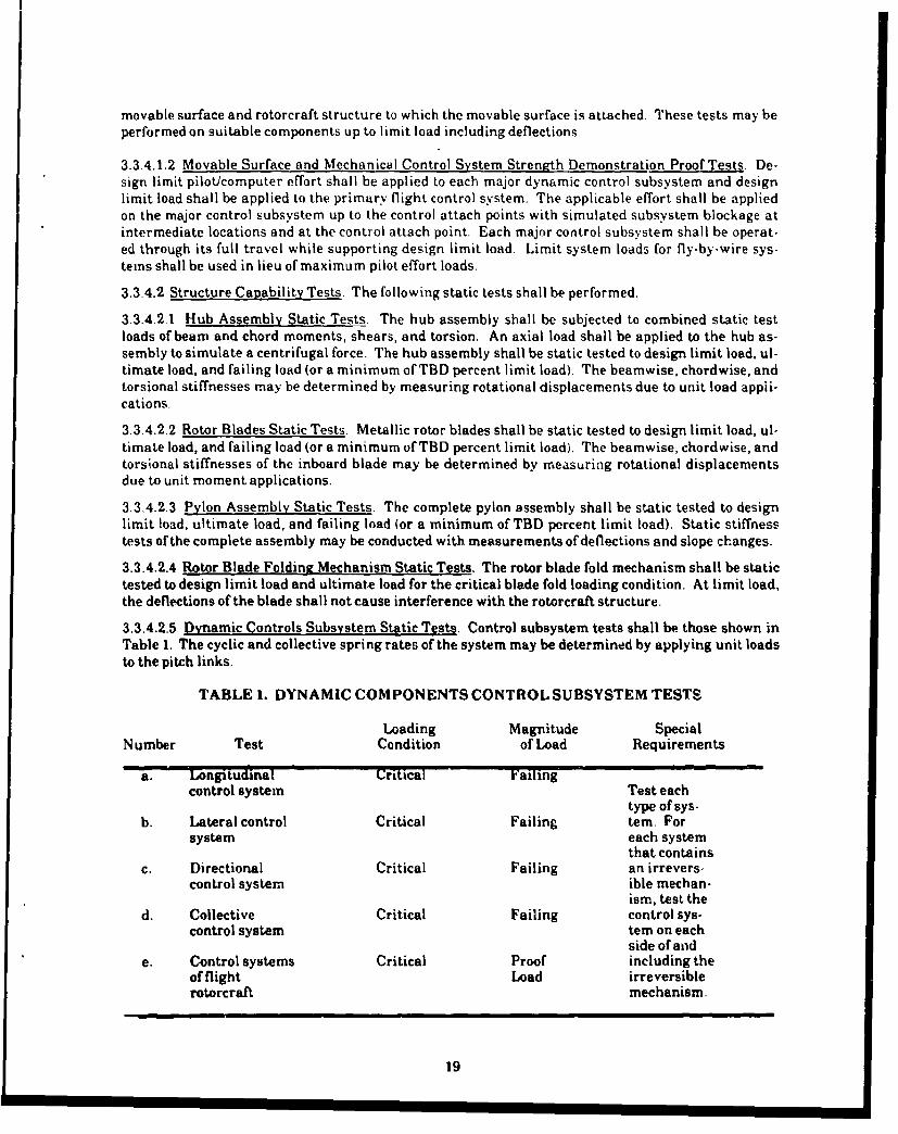
3.3.4.2.5 Dynamic Controls Subsystem Static Tests. Control subsystem tests shall be those shown inTable 1. The cyclic and collective spring rates of the system may be determined by applying unit loadsto the pitch links.
TABLE I. DYNAMIC COMPONENTS CONTROL SUBSYSTEM TESTS
Loading Magnitude SpecialNumber Test Condition of Load Requirements
a. Longitudinal Critical Failingcontrol system Test each
type of sys-b. Lateral control Critical Failing tern. For
system each systemthat contains
c. Directional Critical Failing an irrevers-control system ible mechan-
ism, test thed. Collective Critical Failing control sys-
control system tern on eachside of and
e. Control systems Critical Proof including theof flight Load irreversiblerotorcraft mechanism.
19

3.3.4.2.6 Mast Assembly Static Tests. The transmission housing, if loaded by rotor thrust or shearloads, complete with mast assembly shall be static tested to design limit load, ultimate load, and fail-ing load (ora minimum ofTBD percent limit load).
3.3.4.3 Fatigue, Durability, and Damage Tolerance Tests. Details of the type of fatigue, durability,and damage tolerance tests which are to be conducted will be given in the Airworthiness Qualifica.tionSpecification (AQS) and may depend on the design methodology chosen and the reliability goals of thedetail design requirements. If more than one type of test is required they may be conducted en thesame test article, if applicable.
3.3.4.3.1 Dynamic Components Fatigue Tests. TBD full scale specimens each of the hub, rotor blades,rotor blade attachments, masts, dampers and supports, powered control actuators, and other rotor sys-tem/ dynamic components including transmission housings subjected to vibratory loadings shall be S-N or spectrum tested to failure or to a runout. A minimum of one specimen shall be tested prior to thestartof flight testing and the remainder after the initial flight test loads are available. Manufacturingprocesses and environmental cffects which may affect fatigue strength shall be evaluated.
The test loading shall be based on the mission profile as defined by the detail design requirements andthe flight loads survey, if available. These mission profiles shall be combined with a distribution ofsignificant parameters which may affect life such as cg, altitude, gross weight, load factor/ bank angle,yaw an~gle, sinking speed, roll angle, pitch angle, takeoff-landing speeds, rotor speeds, rotor-hub mo-ments, control loads, torque variations, vibratory loadings, quasi-static loads, and all others pertinentto describing the repeated loads spectra to which the vehicle will be subjected. If spectrum tests areconducted, the spectrum may be truncated based on the resu!ts of S-N tests and strain-life tests.
Runouts/endurance limit need not be carried further than 10x10 6 cycles for steel components, and30x0I cycles for aluminum, magnesium, and titanium components.
3.3.4.3.2 Dynamic Components Durability Tests. Tests shall be conducted to demonstrate compliancewith the durability requirements of the design specification. These tests shall evaluate the ability ofdynamic components to resist cracking or other structural or material degradation such as wear or cor-rosion which could result in excessive maintenance problems, functional problems affecting operation-al readiness, or significant cost impact.
The test loading spectrum shall be based on the mission profile as defined by the detail design require-ments and the flight loads survey, if available. These mission profiles shall be combined with a distri-bution of significant parameters which may affect life such as cg, altitude, gross weight, load fac-tor/bank angle, yaw angle, sinking speed, roll angle, pitch angle, takeoff-landing speed, rotor speeds,rotor-hub moments, control loads, torque variations, vibratory loadings, quasi-static loads, and all oth-ers pertinent to describing the repeated loads spectra to which the vehicle will be subjected. The spec-trum may be truncated based on the results of S-N tests and strain - l.'e tests.
The test environmental effects shall be accounted for in the full scale tests. Inspections shall b¢ •er-formed as a part of the durability tests. These inspections shall consist of design inspections, specialinspections, and teardown inspection.
3.3.4.3.2.1 Rotor Blade Erosion Tests. Sand and rain erosion requirements of the rotor blade and/orerosion protection coverings shall be demonstrated.
20
3.3.4.3.2.2 Rotor Blade Foldiniz Mechanism Durability Tests. The blade fold mechanism shall be test-ed under representative spectrum loads and motions. Environmental effects shall be taken into ac-count.
3.3.4.3.3 Dynamic Components Damage Tolerance Tests. Tests shall be conducted to demonstratecompliance with the damage tolerance requirements of the design specification. The type and quanti-ty of tests depend on the design concepts and the number of fracture critical areas. The types of testsshall include crack growth tests of single and multiple load path structure, residual strength tests, andlife tests of multiple load path structure subsequent to single load path failure for crack arrest evalua-tion.
The test loading spectrum shall be based on the mission profile as defined by the detail design require-ments and the flight loads survey, if available. These mission profiles shall be combined with a distri-bution of significant parameters which may affect life such as cg, altitude, gross weight, load fac-tor/bank angle, yaw angle, sinking speed, roll angle, pitch angle, takeoff-landing speeds, rotor speeds,rotor-hub moments, control loads, torque variations, vibratory loadings, quasi-static loads, and all oth..ers pertinent to describing the repeated loads spectra to which the vehicle will be subjected. The spec-trum may be truncated based on the results of S-N tests and strain-life tests.
The intent shall be to conduct damage tolerance tests of existing test articlesthardware. This may in-clude use of components and assemblies of the design development tests and design verification tests,as well as the full scale static and repeated loads test articles. When necessary, additional structuralcomponents and assemblies shall be fabricated and tested to verify compliance with the damage toler-ance design requirements.
3.3.4.4 Tests for Flight Critical Bearings. Flight critical rolling and sliding element bearings shall betested to determine the bearing life. The number and duration of tests shall be determined I1 y the con-tractor and proposed to the acquisition activity. The bearings shall be tested under rep) 2sentativespectrum loads and motions. Tests shall be conducted to determine the effect of environment on struc-tural properties and performance. Satisfactory completion of predefined pass/tail criteria is requiredfor qualification. Bearing life may be defined as wear, structural degradation, failure to perform theintended function, or combinations thereof.
3.3.5 Post Qualification Tests. Surveillance tests shall be conducted in support of the acquisition ac-tivity's Flight Safety Parts (FSP) program to verify that age and service have no detrimental effect onsafe operation of the flight safety part.
3.4 Dynamic Component (Composite) Test Requirements. The rotorcraft dynamic component compos-ite structures include such items as the rotor blades, fairings, hub, dynamic controls, pylon, rotormast, and transmission housings. The type of tests and number of test articles/specimens must be se-lected to support the chosen reliability methodology.
3.4.1 Dynamic Components Desirn Develoutment Tests. The contractor shall conduct tests to estab-lish design concepts, provide design information, and provide early identification of failure modes anddesign validation. Additionally, the design development tests for composites are a part of the overallstructural qualification procedure in that the test results are used in the interpretation of the full scalestatic and repeated loads test results. Design development tests range in complexity from coupon teststhat are used to evaluate material and fastener behavior to full scale components. Static and repeatedloads tests of dynamic components for design development shall include, but not be limited to, cou-ponlelement and component tests.
21
3.4.1.! CouponfElement Tests. In addition to the coupon/ element tests used to determine the basicmaterial propet ties (design allowables) under the material test program, the coupon/element testsshall include, but not be limited to:
a. Material properties. Material properties tests shall include tests for design allowables,in-plane and interlaminar fracture toughness, constant amplitude and spectrum S-Ncurves for in-plane loads, onset of delamination growth, and delamination growth rate.Specimen configuration shall include open hole, filled hole, loaded hole, and bearingspecimens under static and repeated loads. Hole wear shall be evaluated.
b. Process evaluation. Tests shall be conducted to evaluate new manufacturing processes.
c. Fatigue and damage tolerance evaluation. Tests shall be conducted for fatigue and dam-age tolerance evaluation and shall account for the effects of environment including, butnot limited to, temperature and moisture.
d. Environmental effects and scatter. Tests shall be conducted to determine the effect of en-vironment on static, fatigue, fracture, and delamination growth material properties. Suf-ficient number of specimens shall be tested to develop meaningful statistical parameters.
e. Fastener evaluation and joint configuration evaluation.
34.1.2 Component Tests. Component tests shall be conducted on new design concepts to evaluate:
a. Tooling and assembly process invf:tigation.
b. Strength/stiffness.
c. Fatigue, durability, and damage tolerance evaluation.
d. Environmental effects.
3.4.2 Dynamic Components Design Verification Tests. The contractor shall conduct tests for the pur-pose of early verification of the static strength and repeated loads capability of final or near-finalstructural designs of critical structural areas. Test components/assemblies shall be fabricated usingrepresentative tooling and processes that are proposed for production articles. These tests shall in-ciude, but not be limited to:
a. Nondestructive inspection demonstration.
b. Tooling and assembly process confirmation.
c. Static strength and stiffness verification.
d. Repeated loads capability verification.
e. Destructive inspection. Full scale critical dynamic components made of composite mate-rial shall be cut up and inspected to evaluate the components for manufacturing defectsand to evaluate the manufacturing process. The number of components to be cut up shallbe determined by the contractor.
3.4.3 Tests for Elastomeric Materials. Endurance tests shall be conducted of the elastomeric materialin the assembled configuration. The support structure shall be qualified separately, if necessary. The
22
number and duration of tests shall be defined in the Airworthiness Qualification Specification (AQS).The elastomeric component shall be tested under a representative spectrum of loads, motions, and con-ditions. Environmental effects may be taken into account using coupon specimens.
3.4.4 Dynamic Components Qualification Tests. The contractor shall conduct the following tests offull scale laboratory articles and full scale major assemblies in accordance with the test requirementsspecified herein as modified and amplified by the contract or supporting contractual documentation.
3.4.4.1 Proof Tests. The following proof tests shall be conducted.
3.4.4.1.1 Movable Surface Functional Proof Tests. Movable surfaces including control surfaces, links,actuators, drive system, etc.,shall be tested to determine satisfactory functioning within design operat-ing limits. These tests shall be performed with the associated load induced deflection in the movablesurface and rotorcraft structure to which the movable surface is attached. These tests may be per-formed on suitable components up to limit load including deflections.
3.4.4.1.2 Movable Surface and Mechanical Control System Strength Demonstration Proof Tests. De-sign limit piloticomputer effort shall be applied to each major dynamic control subsystem,and designlimit load shall be applied to the primary flight control system. The applicable effort shall be appliedon the major control subsystem up to the control attach points with simulated subsystem blockage atintermediate locations and at the control attach point. Each major control subsystem shall be operat-ed through its full travel while supporting design limit load. Limit system loads for fly-by-wire sys-tems shall be used in lieu of maximum pilot effort loads.
3.4.4.2 Structure Capability Tests. The following static tests shall be performed.
3.4.4.2.1 Hub Assembly Static Tests. The hub assembly shall be subjected to combined static testloads of beam and chord moments, shears, arid torsion. An axial load shall be applied to the hub as-sembly to simulate a centrifugal force. The hub assembly shall be static tested to design limit load, ul-timate load, and failing load (or a minimum of TBD percent limit load). The beamwise, chordwise, andtorsional stiffnesses may be determined by measuring rotational displacements due to unit load appli-cations.
3.4.4.2.2 Rotor Blades Static Test3. Composite rotor blades shall be static tested to design limit load,ultimate load, and failing load (.)r a minimum of TBD percent limit load). The beamwise, chordwise,and torsional stiffnesses of thi .nboard blade may be determined by measuring rotational displace-ments due to unit moment applications.
3.4.4.2.3 Pylon Assembly Static Tests. The complete pylon assembly shall be static tested to designlimit load, ultimate load, and failing load (or a minimum of TBD percent limit load). Static stiffnesstests of the complete assembly may be conducted with measurements of deflections and slope changes.
3.4.4.2.4 Rotor Blade Folding Mechanism Static Tests. The rotor blade fold mechanism shall be statictested to design limit load and ultimate load for the critical bladp fold loading condition. At limit load,the deflections of the blade shall not cause interference with the rotorcraft structure.
3.4.4.2.5 Dynamic Controls Subsystem Static Tests. Control subsystem tests shall be those shown inTable 1. The cyclic and collective spring rates of the system may be determined by applying unit loadsto the pitch links.
3.4.4.2.6 Mast Assembly Static Tests. The transmission housing, if leaded by rotor thrust or shearloads, complete with mast assembly shall be static tested to limit load, ultimate load, and failing load(or a minimum of TBD percent limit load).
23
3.4.4.3 Fatigue, Durability, and Damage Tolerance Tests. Details of the type of fatigue, durability,and damage tolerance tests which are to be conducted will be given in the Airworthiness QualificationSpecification (AQS) and may depend on the design methodology chosen and the reliability goals of thedetail design requirements. If more than one type of test is required, they may be conducted on thesame test article, if applicable.
3.4.4.3.1 Dynamic Components Fatigue Tests. TBD full scale specimens each of the hub, rotor blades,rotor blade attachments, masts, dampers and supports, powered control actuators, and other rotor sys-tem/dynamic components including transmission housings subjected to vibratory loadings shall be S-N or spectrum tested to failure or to a runout. A minimum of one specimen shall be tested prior to thestart of flight testing and the remainder after the initial flight test loads are available. Manufacturingprocesses and environmental effects which may affect fatigue strength shall be evaluated.
The test loading shall be based on the mission profile as defined by the detail design requirements andthe flight loads survey, if available. These mission profiles shall be combined with a distribution ofsignificant parameters which may affect life such as cg, altitude, gross weight, load factor/bank angle,yaw angle, sinking speed, roll angle, pitch angle, takeoff-landing speeds, rotor speeds, rotor-hub mo-ments, control loads, torque variations, vibratory loadings, quasi-static loads, and all others pertinentto describing the repeated loads to which the vehicle will be subjected. If spectrum tests are conducted,the spectrum may be truncated based on the results of S-N tests.
Runouts/endurance limit need not be carried further than 30x10 6 cycles for composites.
3 4.4.3.2 Dynamic Components Durabilitv Tests. Tests shall be conducted to demonstrate compliancewith the durability requirements of the w.sign specification. These tests shall evaluate the ability ofdynamic components to resist crackin, delamination, or other structural or material degradationsuch as wear which could result in ex ussive maintenance problems, functional problems affectingoperational readiness, or significant coi mpact.
The test loading spectrum shall be based' on the mission profile as defined by the detail design require-ments and the flight loads survey, if available. These mission profiles shall be combined with a distri-bution of significant parameters which may affect life such as cg, altitude, gross weight, load fac-tor/bank angle, yaw angle, sinking speed, roll angle, pitch angle, takeoff-landing speed, rotor speeds,rotor-hub moments, control loads, torque variations, vibratory loadings, quasi-static loads, and all oth-ers pertinent to describing the repeated loads spectrum to which the vehicle will be subjected. Thespectrum may be truncated based on the results of S-N tests.
The test environmental effects shall be accounted for in the full scale tests. Inspections shali be per-formed as a part of the durability tests. These inspections shall consist of design inspections, specialinspections, and teardown inspection.
3.4.4.3.2.1 Rotor Blade Erosion Tests. Sand and rain erosion requirements of the rotor blade and/orerosion protection coverings shall be demonstrated.
3.4.4.3.2.2 Rotor Blade Folding Mechanism Durability Tests. The blade fold mechanism shall be test-ed under representative spectrum loads and motions. Environmental effects shall be taken into ac-count.
3.4.4.3.3 Dynamic Components Damage Tolerance Tests. Tests shall be conducted to demonstrate
compliance with the damage tolerance requirements of the design specification. The type and quanti-ty of tests depend on the design concepts and the number of fracture critical areas. The types of testsshall include flaw growth tests of single and multiple load path structure, residual strength tests, and
life tests of multiple load path structure subsequent to single load path failure for flaw arrest evalua-tion.
24
The test loading spectrum shall be based on the mission profile as defined by the detail design require-ments and the flight load survey, if available. These mission profiles shall be combined with a distri-bution of significant parameters which may affect life such as cg, altitude, gross weight, load fac-tor/bank angle, yaw angle, sinking speed, roll angle, pitch angle, takeoff-landing speeds, rotor speeds,rotor-hub moments, control loads, torque variations, vibratory loadings, quasi-static loads, and all oth-ers pertinent to describing the repeated loads spectra to which the vehicle will be subjected. The spec-trum may be truncated based on the results of S-N tests
The intent shall be to conduct damage tolerance tests of existing test articles/hardware. This may in-clude use of components and assemblies of the design development tests and design verification tests,as well as the full scale static and repeated loads test articles. When necessary, additional structuralcomponents and assemblies shall be fabricated and tested to verify compliance with the damage toler-ance design requirements.
3.4.4.4 Tests for Flight Critical Bearings. Flight critical rolling and sliding element bearings shall betested to determine the bearing life. The number and duration of tests shall be determined by the con-tractor and proposed to the acquisition activity. The bearings shall be tested under representativespectrum loads and motions. Tests shall be conducted to determine the effect of environment on struc-tural properties and performance. Satisfactory completion of a predefined pass/fail criteria is requiredfor qualification. Bearing life may be defined as wear, structural degradation, failure to perform theintended function, or combinations thereof.
3.4.5 Post Qualification Tests. Surveillance tests shall be conducted in support of the acquisition ac-tivity's Flight Safety Parts (FSP) program to verify that age and service have no detrimental effect onsafe operation of the flight safety part.
25