Embed Size (px)
Citation preview

1
Aviation Environmental Design Tool (AEDT)
Supplemental January 2018

Aviation Environmental Design Tool Supplemental _____________________________________________________________________
2
Purpose The Federal Aviation Administration Office of Environment and Energy (FAA-AEE) recognizes that the environmental consequences stemming from the operation of commercial aviation – primarily noise, emissions, and fuel consumption – are highly interdependent and occur simultaneously throughout all phases of flight. The Aviation Environmental Design Tool (AEDT) is a software system that is designed to model aviation related operations in space and time to compute noise, emissions, and fuel consumption.
This document was created to be used in conjunction with the AEDT User Guide, providing detailed guidance on building simple noise and emissions studies in AEDT and importing studies created using either the FAA’s Integrated Noise Model (INM) or the Emissions and Dispersion Modeling System (EDMS).
Appendix A: Quick Start Tutorial The purpose of this section is to introduce you to the basic features required to run the AEDT application to generate noise and emissions results. AEDT has many additional features and settings that support a wide variety of analyses which are covered in detail in the AEDT User Guide.
You will be guided through:
• Creating a new study
• Adding an airport
• Viewing an airport layout
• Creating flight tracks
• Adding receptors and receptor sets
• Adding aircraft operations
• Adding annualizations
• Creating and running metric results
• Viewing noise, emissions and fuel burn output
Appendix B: EDMS Import
AEDT supports the conversion of EDMS studies into an AEDT study database to support users who wish to model studies created in EDMS using the latest noise and emissions modeling algorithms. This section provides instruction on how to import an EDMS study into AEDT. You will be guided through:
• How to import an EDMS study
• How to resolve common errors and warnings when translating from EDMS to ASIF XML
• How to resolve common errors and warning when importing an ASIF XML file into AEDT
• How to reimport a corrected ASIF file
• Additional tips on comparing results between EDMS and AEDT
Appendix C: INM Import

Aviation Environmental Design Tool Supplemental _____________________________________________________________________
3
AEDT supports the conversion of INM studies into an AEDT study database to support users who wish to model studies created in INM using the latest noise and emissions modeling algorithms. This section provides instruction on how to import an INM study into AEDT. You will be guided through:
• How to import an INM study
• How to resolve common errors and warnings when translating from INM to ASIF
• How to resolve common errors and warning when importing an ASIF XML file into AEDT
• How to reimport a corrected ASIF file
• Additional tips on comparing results between INM and AEDT
Aviation Environmental Design Tool Supplemental _____________________________________________________________________
4
Contents
Table of Figures ................................................................................................................................................ 7
Introduction ..................................................................................................................................................... 9
Technical Assistance ......................................................................................................................................... 9
Getting Started ...............................................................................................................................................10
What is an AEDT Study? .................................................................................................................................10
Installing AEDT ...............................................................................................................................................10
Starting the AEDT Application ........................................................................................................................10
The AEDT User Interface Organization ..........................................................................................................11
Appendix A: Quick Start Tutorial ....................................................................................................................12
1. Create a New Study ................................................................................................................................12
2. Add an Airport ........................................................................................................................................14
3. View the Airport Layout .........................................................................................................................14
4. Creating Flight Tracks .............................................................................................................................16
5. Add Receptors and Receptor Sets ..........................................................................................................21
6. Add Aircraft Operations .........................................................................................................................24
7. Add an Annualization .............................................................................................................................26
8. Create Metric Result ..............................................................................................................................28
9. Running a Metric Result .........................................................................................................................30
10. View Output ...........................................................................................................................................31
Appendix B: Importing EDMS Studies into AEDT ...........................................................................................36
1. AEDT Standard Input File .......................................................................................................................36
2. Before You Import ..................................................................................................................................36
3. Import the EDMS study through the AEDT Application .........................................................................36
4. Resolving EDMS to ASIF Import Errors ...................................................................................................40
4.1. EDMS to ASIF XML Conversion Errors ....................................................................................................40
4.1.1. Resolving File Import Errors ...........................................................................................................40
4.1.2. Resolving EDMS Input Data File Errors (EDMS to ASIF XML) .........................................................41
4.2. Resolving Data Integrity Errors (ASIF XML Validation) ...........................................................................42
Aviation Environmental Design Tool Supplemental _____________________________________________________________________
5
5. Importing an EDMS study using an external tool (EDMS2ASIF) ............................................................54
5.1. Creating an ASIF XML from an EDMS study ...........................................................................................55
5.2. Re-importing the ASIF file ......................................................................................................................56
6. Comparing EDMS Results in AEDT .........................................................................................................56
6.1. Emissions Methodology Differences......................................................................................................57
6.1.1. FOA Methodology for Particulate Matter ......................................................................................57
6.1.2. Particulate Matter Categorization .................................................................................................57
6.1.3. Airport Weather .............................................................................................................................57
6.2. Aircraft Performance Input Differences.................................................................................................57
6.2.1. Airport Definition ...........................................................................................................................57
6.2.2. Single-Airport Weather ..................................................................................................................58
6.2.3. Bank Angle .....................................................................................................................................58
6.2.4. Taxi Time-in-Mode Fuel Flow .........................................................................................................58
6.3. Aircraft Performance Computation Differences ....................................................................................58
6.3.1. Truncation at Mixing Height ..........................................................................................................58
6.3.2. Fuel Flow Rate Computation Methodology ...................................................................................59
6.4. EDMS vs AEDT Database Differences .....................................................................................................59
Appendix C: Importing an INM study .............................................................................................................60
1. AEDT Standard Input File .......................................................................................................................60
2. Before You Import ..................................................................................................................................60
3. Importing an INM Study in the AEDT Application ..................................................................................60
4. Resolving Import Errors .........................................................................................................................64
4.1. INM to ASIF XML Conversion Errors ......................................................................................................64
4.1.1. Resolving File Import Errors ...........................................................................................................64
4.1.2. Resolving INM Input Data File Errors (INM to ASIF XML) ..............................................................65
4.2. Resolving Data Integrity Errors (ASIF XML Validation) ...........................................................................67
5. Importing an INM study using an external tool (INM2ASIF) ..................................................................76
5.1. Creating an ASIF XML from an INM study ......................................................................................76
5.2. Re-importing the ASIF file ......................................................................................................................76
6. Comparing INM Results in AEDT ............................................................................................................77

Aviation Environmental Design Tool Supplemental _____________________________________________________________________
6
6.1. Single-Airport Weather ..........................................................................................................................77
6.2. Bank Angle .............................................................................................................................................77
6.3. Atmospheric Absorption ........................................................................................................................77

Aviation Environmental Design Tool Supplemental _____________________________________________________________________
7
Table of Figures Figure 1 - Accelerated Display Warning ...........................................................................................................10 Figure 2- Map View...........................................................................................................................................11 Figure 3- Create New Study ..............................................................................................................................13 Figure 4- Metric Results Tab .............................................................................................................................13 Figure 5- Add Existing Airport ...........................................................................................................................14 Figure 6- Airport Layout Map View ..................................................................................................................15 Figure 7- Airport Layout Details Pane ...............................................................................................................15 Figure 8- Airports Designer Tab ........................................................................................................................16 Figure 9- Create Vector Track ...........................................................................................................................17 Figure 10- Vector Track Details ........................................................................................................................18 Figure 11- Add Point Track ...............................................................................................................................18 Figure 12- Map of Runway End ........................................................................................................................19 Figure 13- Arrival Point Track ...........................................................................................................................20 Figure 14- Map View of Tracks .........................................................................................................................20 Figure 15- Definitions Tab – Receptors ............................................................................................................21 Figure 16- Receptor Details ..............................................................................................................................22 Figure 17- Receptor Details Point .....................................................................................................................23 Figure 18- Receptor Set Details ........................................................................................................................23 Figure 19- Map View of Receptor Set ...............................................................................................................24 Figure 20- Create Aircraft Operations ..............................................................................................................25 Figure 21- Create Aircraft Operations – Choose Equipment ............................................................................25 Figure 22- Create Aircraft Operations - Summary ............................................................................................26 Figure 23- Create Aircraft Operations Groups .................................................................................................27 Figure 24- Copy Metric Result ..........................................................................................................................29 Figure 25- Metric Results and Details Pane ......................................................................................................30 Figure 26- Metric Results Pane .........................................................................................................................31 Figure 27- Task Completed Message ................................................................................................................31 Figure 28- Contour Layers on Map ...................................................................................................................32 Figure 29- Contour Layer Attributes .................................................................................................................33 Figure 30- Metric Results Tab - Reports ...........................................................................................................33 Figure 31- Noise Exposure Report ....................................................................................................................34 Figure 32- Emissions Report (Segment) ...........................................................................................................35 Figure 33 - Choose study location ....................................................................................................................36 Figure 34- EDMS to ASIF Error warning ............................................................................................................37 Figure 35- Review study content - bad data integrity ......................................................................................37 Figure 36- review study content - Asif raw ......................................................................................................38 Figure 37- review study content - details .........................................................................................................38 Figure 38- Review data conflicts .......................................................................................................................39 Figure 39- Complete study import ...................................................................................................................39 Figure 40- ASIF xml ...........................................................................................................................................43 Figure 41- xml study .........................................................................................................................................44 Figure 42- xml Userdefinedairportset ..............................................................................................................44 Figure 43- xml element scenarioairportlayouttype ..........................................................................................45 Figure 44- xml element scenario ......................................................................................................................48
Aviation Environmental Design Tool Supplemental _____________________________________________________________________
8
Figure 45- XML element case ...........................................................................................................................49 Figure 46- reference -> case and scenario .......................................................................................................50 Figure 47- xml element track ............................................................................................................................52 Figure 48- element operation - 1 -> 2 -> 3 .......................................................................................................53 Figure 49- element operation - 4 -> 5 ..............................................................................................................54 Figure 50- EDMS to ASIF ...................................................................................................................................56 Figure 51 - Choose study location ....................................................................................................................61 Figure 52- INM to ASIF Error warning ..............................................................................................................61 Figure 53- Review study content - bad data integrity ......................................................................................61 Figure 54- review study content - Asif raw ......................................................................................................62 Figure 55- review study content - details .........................................................................................................62 Figure 56- Review data conflicts .......................................................................................................................63 Figure 57- Complete study import ...................................................................................................................64 Figure 58- ASIF xml ...........................................................................................................................................68 Figure 59- xml study .........................................................................................................................................69 Figure 60- xml userdefinedairportset ...............................................................................................................69 Figure 61 - xml element scenario .....................................................................................................................70 Figure 62 - xml element case ............................................................................................................................71 Figure 63 - reference -> case and scenario.......................................................................................................72 Figure 64 - xml element track ...........................................................................................................................73 Figure 65 - element operation - 1 -> 2 -> 3 ......................................................................................................74 Figure 66 - element operation - 4 -> 5..............................................................................................................75 Figure 67- INM to ASIF ......................................................................................................................................76

Aviation Environmental Design Tool Supplemental _____________________________________________________________________
9
Introduction This document was created as an extension of the AEDT User Guide for the purpose of:
• Providing more detailed guidance on creating simple noise and emissions studies in AEDT.
• Providing guidance on how to import EDMS studies, including tips on resolving import errors.
• Providing guidance on how to import INM studies, including tips on resolving import errors.
Each section of the appendix is meant to encompass all of the necessary information to complete the desired task. You do not need to read this document in its entirety to successfully create or import a study, however, it is recommended that you review the Getting Started section prior to using the information in appendices A – C.
This document references portions of the AEDT User Guide, available on the AEDT Support website. Additional documentation on AEDT, including the AEDT Technical Manual, AEDT ASIF Reference Guide, and the AEDT NEPA Guidance document, is also available on the support website. This document does not contain guidance or policy for regulatory analyses. Reference the AEDT NEPA Guidance document for guidance in conducting environmental modeling for FAA actions subject to NEPA.
The following symbols will appear throughout the document to highlight important information:
Observe warnings to avoid errors in execution and ensure that the intended execution occurs.
Notes contain helpful information and tips regarding the functionality of the tool.
Technical Assistance The AEDT Support website, https://aedt.faa.gov/, is the technical support hub for AEDT. Support requests, feedback on issues or bugs, and feature requests should be submitted through this website. The latest AEDT installers and support resources such as documentation and frequently asked questions (FAQ) are also available on the AEDT Support website. Register on the website to purchase products, request support, or submit feedback on AEDT. Additional options for support include:
• E-mail: [email protected]
• Phone: 617-494-2603
Please include the AEDT Administrative File when requesting technical support. Please refer to Section 4.12.2 of the AEDT User Guide for instructions on generating the Administrative File.

Aviation Environmental Design Tool Supplemental ____________________________________________________________________
10
Getting Started
What is an AEDT Study?
An AEDT study is a collection of user inputs, system data, user settings and computed results. This data is contained in a single SQL Server database with a user specified name. The study database contains all of the tables required by AEDT. FLEET and AIRPORT system data is added to the study database when the study is created. A study database does not contain external files such as terrain or high-fidelity weather data files.
Installing AEDT If AEDT is not already installed, follow the instructions provided with the AEDT Installation Guide to install the application and SQL Server 2012 software, before proceeding. All required software is available for download on the AEDT Support website (Section 1.3).
AEDT requires administrative privileges for both 1) installation and 2) execution of the software.
Starting the AEDT Application
1. On the Desktop, right-click on the AEDT shortcut and click Run as administrator.
• AEDT can also be accessed by navigating to C:\Program Files\FAA\AEDT and right-clicking on the executable named FAA.AEE.AEDT.GUI.View.Ribbon.exe and selecting Run as administrator.
2. If accelerated display is unavailable on the host platform where AEDT is launched, the following warning message will be displayed (Figure 1).
• Check the Do not show this message again checkbox to disable this warning message.
• Click Close to close the dialog.
Figure 1 - Accelerated Display Warning
When the accelerated display is disabled, rendering map layers (e.g. receptor set layers) may
require additional processing time. In some cases, map features may not be highlighted when
selected on the map using the Identify tool or through the layer attributes pane.

Aviation Environmental Design Tool Supplemental ____________________________________________________________________
11
The AEDT User Interface Organization The AEDT User Interface work area is described below (Figure 2):
Figure 2- Map View
The work areas in the AEDT interface are divided into three sections. While the divisions are consistent between tabs, the content changes as appropriate for each tab. 1. Left Work Area The left work area contains a list of data available for use in the currently selected tab. 2. Center Work Area The center work area contains map, detail, or report content, depending on the selected tab and view. 3. Right Work Area The right work area provides appropriate tools to manage the content in the center work area.
AEDT features are organized by tabs as follows:
1. Study tab The Study tab includes the following menu options:
• Open: opens the Open Study dialog.
• Import: opens the Import Study dialog.
• Partial Import: opens the Import Partial ASIF dialog.
• New: opens the Create New Study dialog.
Application Button & Quick Access Toolbar
Ribbon Tabs
Ribbon Groups
Left Work Area
Status Bar
Ribbon
Center
Work
Area
Right
Work
Area

Aviation Environmental Design Tool Supplemental ____________________________________________________________________
12
• Close: closes the currently open study.
• Recent: lists recently opened studies.
• Tasks: displays active and completed tasks.
• Log: displays AEDT log messages.
• Preferences: contains system and study settings.
• Study Maintenance: contains study maintenance options.
• Help: displays AEDT version and support information.
• Exit: exits the AEDT application. 2. Metric Results tab
The Metric Results tab supports construction and processing of metric result definitions, generation of reports, and generating and viewing result layers.
3. Operations tab The Operations tab supports managing aircraft operations, non-aircraft operations, runup operations, helitaxi operations, and annualizations.
4. Equipment tab The Equipment tab supports managing aircraft equipment, non-aircraft equipment, and equipment groups.
5. Airports tab The Airports tab supports adding airports, viewing airport layouts and editing its components, adding new components in airport layout designer, and creating operation configurations.
6. Definitions tab The Definitions tab supports setting up study data elements including metrics, receptors, receptor sets, operational profiles, and weather and terrain settings. It also supports integration of emissions results from the EPA’s Motor Vehicle Emission Simulator (MOVES).
Appendix A: Quick Start Tutorial The purpose of this section is to guide you through each step required to generate and view noise and emissions output in AEDT for a single aircraft.
1. Create a New Study Begin by creating a new AEDT study:
1. Click the Study tab then click New to display the Create New Study dialog. 2. Enter the name “NoiseAndEmissionsStudy”. 3. Enter the description “A simple noise and emissions Study”. Note that the study description is
optional. 4. Enter the name of the desired SQL Server instance in the Select database server field.
• To change the SQL Server login credentials: a. Click the Credentials arrow button. b. Select desired authentication mode from the Authentication drop-down menu.
▪ Windows Authentication: The User name is pre-populated. ▪ SQL Server Authentication: Enter the User name and Password.
c. Click Test Connection to verify that the connection to the database is successful. 5. Click New to create a new study (Figure 3).

Aviation Environmental Design Tool Supplemental ____________________________________________________________________
13
Figure 3- Create New Study
AEDT will automatically create a SQL database named “NoiseAndEmissionsStudy” on your SQL Server instance. This study will be populated with all of the necessary tables used by AEDT. Fleet and airport data tables (those tables with the prefix “FLT_” and “APT_” respectively) are automatically populated with data from the FLEET and AIRPORT databases downloaded as part the AEDT installation package.
Upon creating the study, the Metric Results tab will display the Map (Figure 4).
Figure 4- Metric Results Tab

Aviation Environmental Design Tool Supplemental ____________________________________________________________________
14
2. Add an Airport 1. Click Add, then click Existing Airport. 2. In the Add Existing Airport dialog (Figure 5):
a. Filter the airports by “Preferred Code” by clicking on the filter icon . b. Type in “KSFO” under the “Is Equal To” drop down. c. Select “Filter”. d. Close the “Filter” dialog.
3. Click Add to add the selected airport to the study.
Figure 5- Add Existing Airport
Once you select Add, you will be returned to the Map view under the Airports tab.
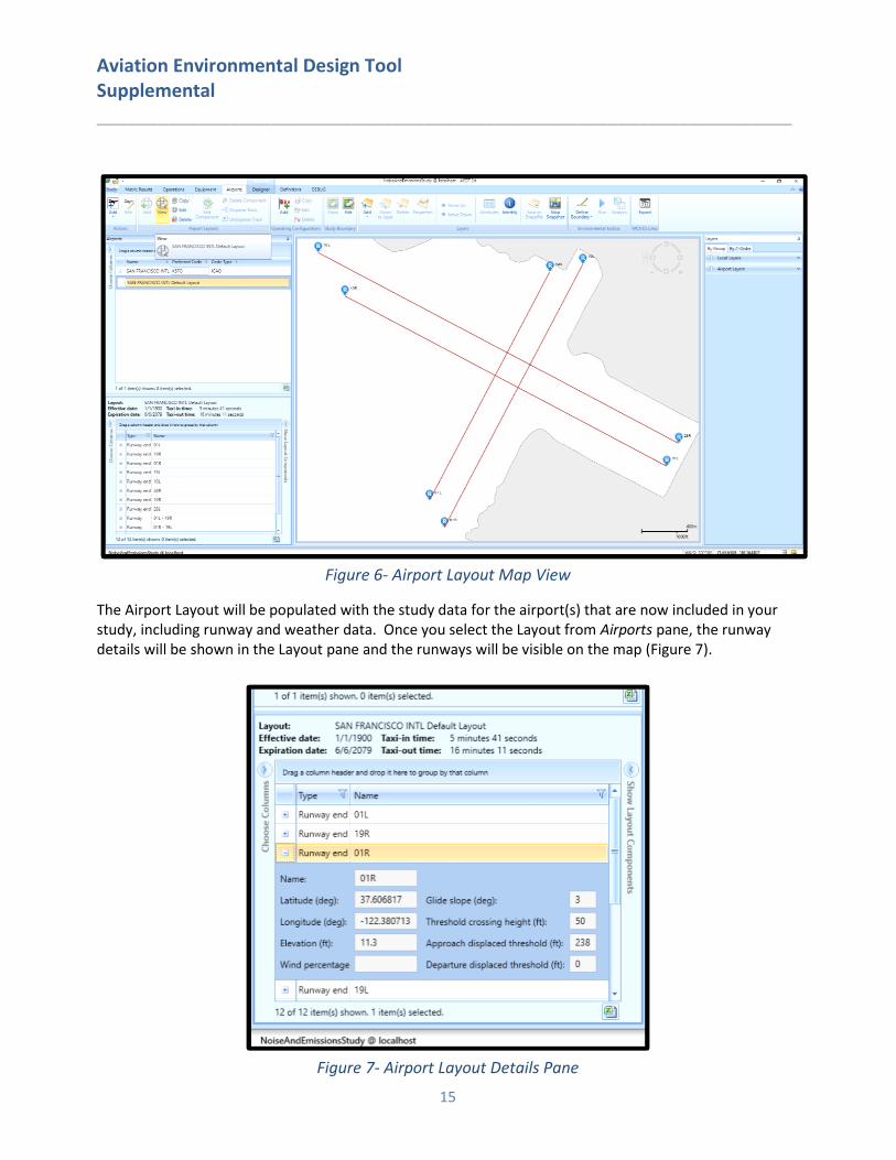
3. View the Airport Layout Once you have added an airport, a default Airport Layout will be created (Figure 6).
Aviation Environmental Design Tool Supplemental ____________________________________________________________________
15
Figure 6- Airport Layout Map View
The Airport Layout will be populated with the study data for the airport(s) that are now included in your study, including runway and weather data. Once you select the Layout from Airports pane, the runway details will be shown in the Layout pane and the runways will be visible on the map (Figure 7).
Figure 7- Airport Layout Details Pane

Aviation Environmental Design Tool Supplemental ____________________________________________________________________
16
4. Creating Flight Tracks Flight tracks the trace path of the flight trajectory on the horizontal plane. Flight tracks are defined as either as vector-type tracks (consisting of one or more straight or curved segments), or point-type tracks (consisting of an array of x,y points). We will be creating a departure vector track and an arrival point-type track. AEDT automatically extends departure and arrival tracks during flight performance processing, so that the entirety of the vertical profile can be computed. Refer to the AEDT User Guide, section 8.3.6.3, for more information.
Create a Vector Departure Track
1. Select the Airports Designer tab (Figure 8). AEDT will load all of the airport layout features.
Figure 8- Airports Designer Tab
2. Click Add Vector Track, and select Departure. The Create Vector Track pane will show in the lower
right hand corner. Note that the fields marked with a red (*) are required (Figure 9).

Aviation Environmental Design Tool Supplemental ____________________________________________________________________
17
Figure 9- Create Vector Track
3. Enter the name “DepartureVectorTrack”. 4. On the Map display, click on the runway end “01L”. AEDT will automatically populate the Runway
End/Helipad in the Create Vector Track pane. 5. Select the Straight vector track segment. 6. Enter “12150” feet (~ 2 nautical miles). 7. Select Add.
You will see the straight track segment on the map. As you add new segments, the map displays them.
8. Set the Turn vector track segment to Left. 9. Enter the Radius “12150” (Feet). 10. Enter the Angle “90” (Degrees). 11. Select Add. 12. Select the Straight vector track segment. 13. Enter “12150” feet (~ 2 nautical miles). 14. Select Add. 15. Select Save.
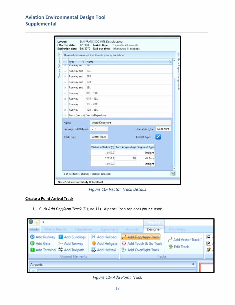
AEDT will add this track to the list of Airport Layout components in the lower left corner (Figure 10).
Aviation Environmental Design Tool Supplemental ____________________________________________________________________
18
Figure 10- Vector Track Details
Create a Point Arrival Track
1. Click Add Dep/App Track (Figure 11). A pencil icon replaces your cursor.
Figure 11- Add Point Track
Aviation Environmental Design Tool Supplemental ____________________________________________________________________
19
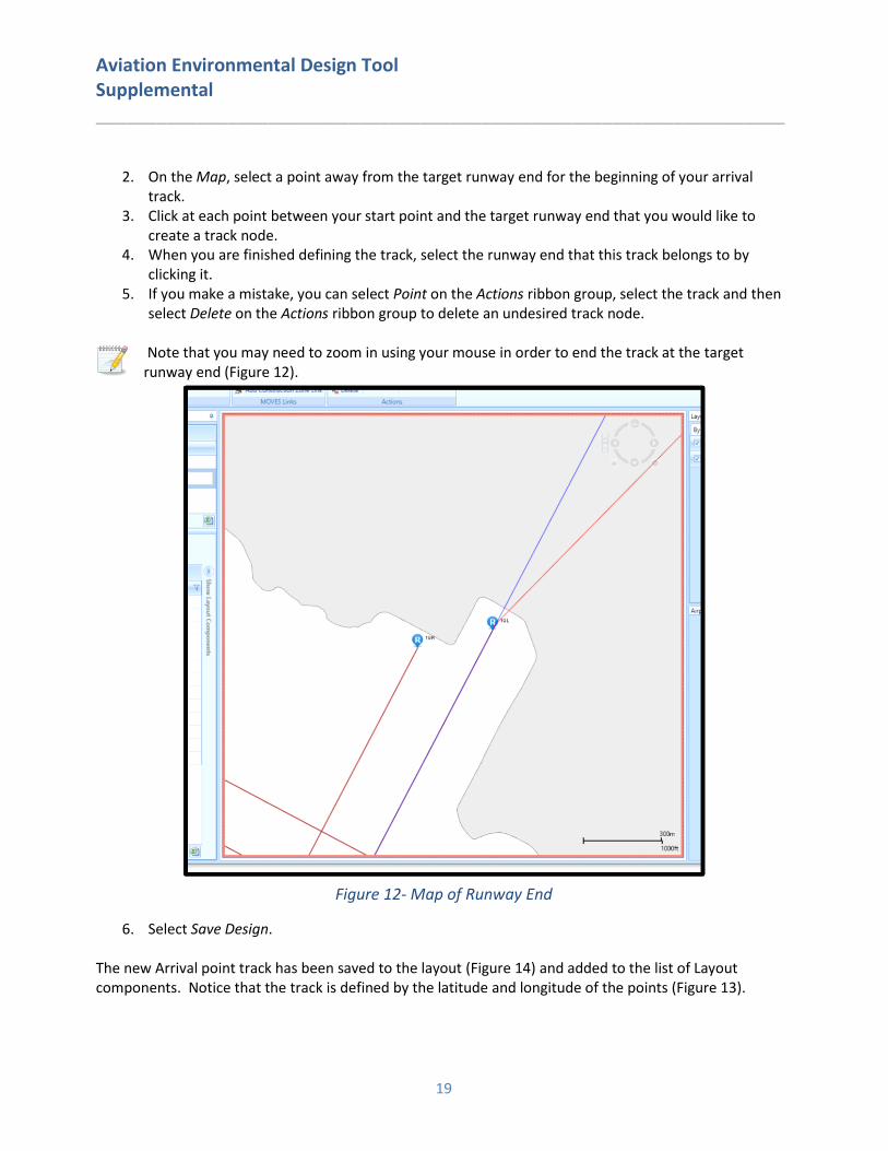
2. On the Map, select a point away from the target runway end for the beginning of your arrival track.
3. Click at each point between your start point and the target runway end that you would like to create a track node.
4. When you are finished defining the track, select the runway end that this track belongs to by clicking it.
5. If you make a mistake, you can select Point on the Actions ribbon group, select the track and then select Delete on the Actions ribbon group to delete an undesired track node.
Note that you may need to zoom in using your mouse in order to end the track at the target runway end (Figure 12).
Figure 12- Map of Runway End
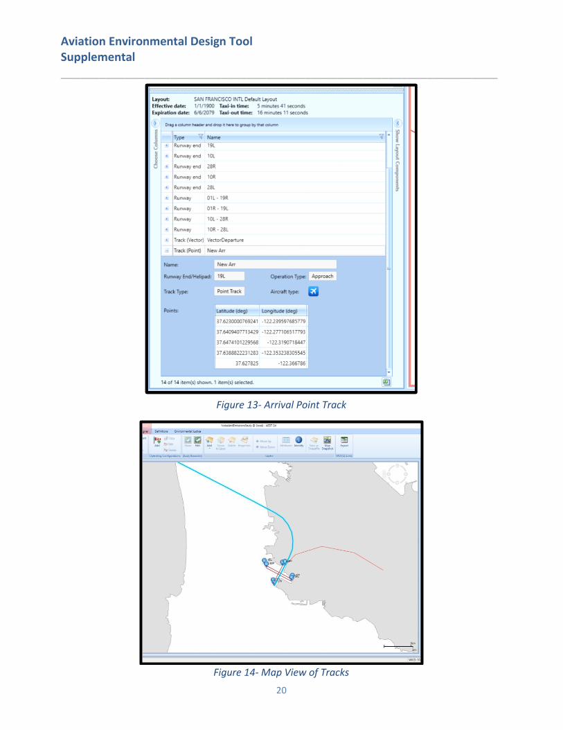
6. Select Save Design. The new Arrival point track has been saved to the layout (Figure 14) and added to the list of Layout components. Notice that the track is defined by the latitude and longitude of the points (Figure 13).
Aviation Environmental Design Tool Supplemental ____________________________________________________________________
20
Figure 13- Arrival Point Track
Figure 14- Map View of Tracks

Aviation Environmental Design Tool Supplemental ____________________________________________________________________
21
5. Add Receptors and Receptor Sets Receptors define locations where noise or pollutant concentration levels are calculated. Receptors and Receptor Sets are not required for flight performance, fuel burn or emissions specific metric results. There are two receptor types in AEDT, Point and Grid. We will create both a Point and a Grid receptor.
Receptors must be added to Receptor Sets prior to noise or pollutant concentration metric result runs.
To create a Receptor:
1. Select the Definitions tab, then select Receptors (Figure 15).
Figure 15- Definitions Tab – Receptors
To define a Grid Receptor (Figure 16):
2. Select the New button in the Actions ribbon group. The Receptor Details window will appear. 3. The initial grid type is set to Point. Select Grid from the Type drop down.
In AEDT, the location of a grid type receptor is specified by the lower left (southwest) corner of the grid, which can be defined by specifying the latitude and longitude of the point or as an offset from a location (typically the airport origin).

Aviation Environmental Design Tool Supplemental ____________________________________________________________________
22
Figure 16- Receptor Details
4. Enter the Name “ContourGrid”. 5. Enter the “32” for the X and Y counts. This represents the number of receptor points in the regular
grid. 6. Enter “0.5” for the X and Y spacing. These values represent the spacing between receptor points.
Both numbers must be equal in order to generate contours in AEDT. 7. Enter “-8” for the X and Y offset. These values indicate the nautical mile offset from the Grid
origin. 8. The Location Info is defaulted to the airport origin. 9. The Restrict by Boundary is defaulted to be off. 10. Select Save.
AEDT will display your new receptor on the left hand pane. You can read more about the Restrict by Boundary functionality in section 9.3.2.1 of the AEDT User Guide. To create a Point Receptor (Figure 17):
1. Select the New button in the Actions ribbon group. The Receptor Details window will appear. 2. The initial grid type is set to Point.
Aviation Environmental Design Tool Supplemental ____________________________________________________________________
23
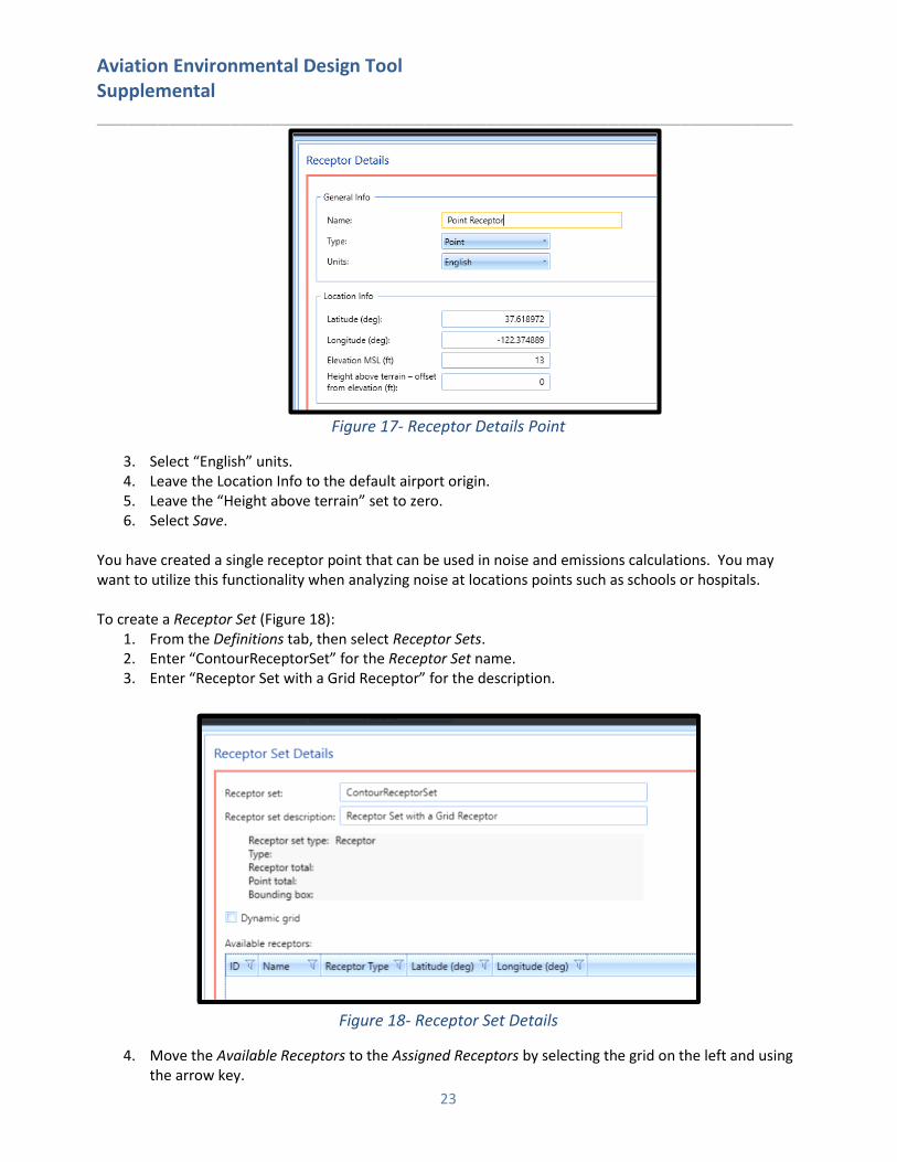
Figure 17- Receptor Details Point
3. Select “English” units. 4. Leave the Location Info to the default airport origin. 5. Leave the “Height above terrain” set to zero. 6. Select Save.
You have created a single receptor point that can be used in noise and emissions calculations. You may want to utilize this functionality when analyzing noise at locations points such as schools or hospitals. To create a Receptor Set (Figure 18):
1. From the Definitions tab, then select Receptor Sets. 2. Enter “ContourReceptorSet” for the Receptor Set name. 3. Enter “Receptor Set with a Grid Receptor” for the description.
Figure 18- Receptor Set Details
4. Move the Available Receptors to the Assigned Receptors by selecting the grid on the left and using the arrow key.

Aviation Environmental Design Tool Supplemental ____________________________________________________________________
24
5. Select Save. Once the Receptor Set is committed, you can view the receptors by selecting the Map from the Display ribbon group and then selecting Receptor Set from the View ribbon group (Figure 19).
Figure 19- Map View of Receptor Set
6. Add Aircraft Operations AEDT can model several types of Aircraft and Non-Aircraft operations. For our study, we will be creating a single airplane arrival operation and a single airplane departure operations. For additional information on other types of operations, please refer to section 6.2 of the AEDT User Guide. To add aircraft operations (Figure 20):
1. Select the Operations tab and then select Aircraft on the Display ribbon. 2. Select Add on the Aircraft Actions ribbon. 3. Click on the airport layout from the list as the selected layout for this operation. (Leave the
operation type as Arrival). 4. Leave the Operation count equal to 1. This will represent one day time operation of the aircraft,
profile and track combination. 5. Select Next.

Aviation Environmental Design Tool Supplemental ____________________________________________________________________
25
Figure 20- Create Aircraft Operations
6. Select the record for the 707120 and select Next (Figure 21).
Figure 21- Create Aircraft Operations – Choose Equipment
7. Select Next (You are not defining Gates). For more information on how to define Gates, see section 6.2.1.3 of the AEDT User Guide.
8. Select Next (You are not defining GSE/APU). For more information on how to define GSE or APU’s,

Aviation Environmental Design Tool Supplemental ____________________________________________________________________
26
see section 6.2.1.4 of the AEDT User Guide. 9. Select an operation time. The default time and date are the date of the study at midnight. Change
this value to the current date, but at 11 AM. Select Next.
Operation time is critical for noise metrics and annualization. For example, DNL noise applies a 10 decibel penalty for night time operations.
10. Select the STANDARD arrival profile for the 707120 (there is only one) from the Choose Flight Profile window and select Next.
11. Select the track named “New Arr” and select Next. The summary of your input will appear at the top of the Summary window (Figure 22). Select Create.
Figure 22- Create Aircraft Operations - Summary
Repeat the process to create a departure operation. AEDT will filter available profiles, tracks and other data that are specific to the operation type you are defining.
7. Add an Annualization In AEDT, an annualization is a hierarchical grouping of operations associated with the following parameters:
• Time period to be analyzed • Operations included in the time period • Weighted groupings of the included operations • Modeling options for the included operations
Annualization provides a convenient way to adjust contributions of individual operation groups by scaling operations up or down using weightings and to model alternative scenarios from a baseline scenario. To create an annualization:
1. Select Annualizations on the Operations tab. 2. Select New under Annualization Actions. 3. On the Create Annualizations window, check Add new aircraft operation group(s). 4. Select Next.
Aviation Environmental Design Tool Supplemental ____________________________________________________________________
27
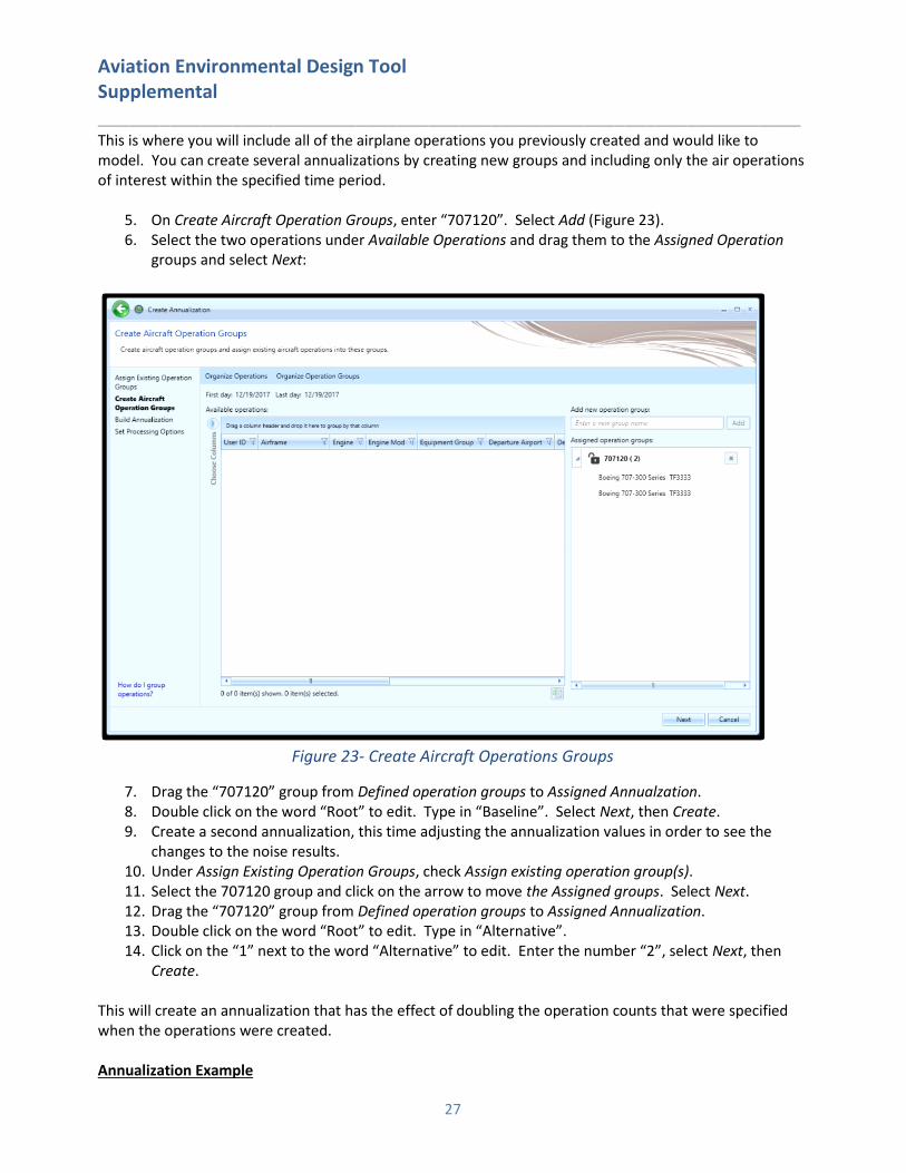
This is where you will include all of the airplane operations you previously created and would like to model. You can create several annualizations by creating new groups and including only the air operations of interest within the specified time period.
5. On Create Aircraft Operation Groups, enter “707120”. Select Add (Figure 23). 6. Select the two operations under Available Operations and drag them to the Assigned Operation
groups and select Next:
Figure 23- Create Aircraft Operations Groups
7. Drag the “707120” group from Defined operation groups to Assigned Annualzation. 8. Double click on the word “Root” to edit. Type in “Baseline”. Select Next, then Create. 9. Create a second annualization, this time adjusting the annualization values in order to see the
changes to the noise results. 10. Under Assign Existing Operation Groups, check Assign existing operation group(s). 11. Select the 707120 group and click on the arrow to move the Assigned groups. Select Next. 12. Drag the “707120” group from Defined operation groups to Assigned Annualization. 13. Double click on the word “Root” to edit. Type in “Alternative”. 14. Click on the “1” next to the word “Alternative” to edit. Enter the number “2”, select Next, then
Create.
This will create an annualization that has the effect of doubling the operation counts that were specified when the operations were created. Annualization Example

Aviation Environmental Design Tool Supplemental ____________________________________________________________________
28
Assume you have grouped all of your airport operations into an arrival group and a departure group. These groups are part of your baseline scenario, which is utilized 75% of the year. Suppose you would like to compare your baseline operating configuration against an alternative. The alternative operating configuration contains the same operation groups as the baseline and is utilized 25% of the year. However, the alternative scenario allows for twice as many arrivals as the baseline. For this example, you would:
1. Create two operation groups: one for all arrivals and one for all departures. 2. Add both operation groups to an annualization named “Baseline”. 3. Set the “Baseline” weighting to 0.75. 4. Create a second annualization named “Alternative”. 5. Add both operation groups to the annualization. Set the weighting of the arrival group to “2”. 6. Set the “Alternative” weighting to 0.25. 7. Run identical metric results, one for each annualization. 8. Compare noise results.
Please see section 6.6 of the AEDT User Guide for more information on Annualizations.
8. Create Metric Result An AEDT Metric Result contains all of the information required for an analyst to generate results in AEDT. Examples of metric result input include: aircraft operations data, flight performance modeling options, result storage options and noise and emissions metric selections. To create a metric result for a simple noise and emissions analysis:
1. Select the Metric Results tab, then select Define under the Metric Result Actions ribbon. 2. Move the “DNL”metric from the Available Metrics to the Selected Metrics by using the arrow.
Select Next. 3. Move the “ContourReceptorSet” from the Available receptor set to Selected by using the arrow.
Select Next. 4. Select the “Baseline” Annualization. You should see the Annualization under Annualization Details.
Select Next. The Set Processing Options view contains many types of modeling and data storage options. It is here that you define your weather usage, terrain usage and performance modeling details. Additional information on the use of these options can be found in the AEDT User Guide.
5. Under Result Storage Options, Emissions, select Segment. Selecting Segment will persist segment level emissions results to the study database and allow you to view these in the Emissions Report.
6. Under Emissions/Performance Modeling, under Weather Fidelity, select “Use Airport Weather” . When this option is selected, average annual airport weather (specified in the Definitions tab, Weather, Airport weather) is used. If any weather data is missing, AEDT will not substitute the missing data with ISA weather.
7. Under the Metric Result Options, under Name, enter “DNL Baseline”. Select Next and then Create. To create an Alternative Metric Result:
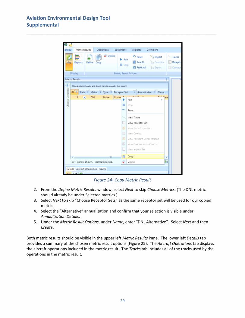
1. Select the Basline metric result under the Metric Results ribbon, right-click and select Copy (Figure 24).
Aviation Environmental Design Tool Supplemental ____________________________________________________________________
29
Figure 24- Copy Metric Result
2. From the Define Metric Results window, select Next to skip Choose Metrics. (The DNL metric should already be under Selected metrics.)
3. Select Next to skip “Choose Receptor Sets” as the same receptor set will be used for our copied metric.
4. Select the “Alternative” annualization and confirm that your selection is visible under Annualization Details.
5. Under the Metric Result Options, under Name, enter “DNL Alternative”. Select Next and then Create.
Both metric results should be visible in the upper left Metric Results Pane. The lower left Details tab provides a summary of the chosen metric result options (Figure 25). The Aircraft Operations tab displays the aircraft operations included in the metric result. The Tracks tab includes all of the tracks used by the operations in the metric result.

Aviation Environmental Design Tool Supplemental ____________________________________________________________________
30
Figure 25- Metric Results and Details Pane
9. Running a Metric Result AEDT allows you to select and run more than one metric result at a time. To do this, select Run All under the Metric Result Actions ribbon. As your metric results are being computed, you will see the percent completed under the State column. Once the metric results are completed, the State column will display a green check (Figure 26). Additionally, you will see a “Task Completed” message in the lower right corner (Figure 27).

Aviation Environmental Design Tool Supplemental ____________________________________________________________________
31
Figure 26- Metric Results Pane
Figure 27- Task Completed Message
10. View Output
Noise Contour Layer To view contour layers:
1. Select the metric result from the Metric Results pane. 2. Right click and select View Contours. The Contour Settings dialog will be displayed. 3. Set the contour minimum to “50”. Select OK. 4. Repeat steps 1-3 for the Alternative Result.
Aviation Environmental Design Tool Supplemental ____________________________________________________________________
32
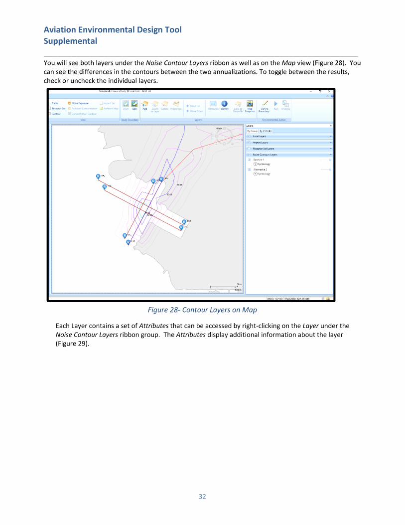
You will see both layers under the Noise Contour Layers ribbon as well as on the Map view (Figure 28). You can see the differences in the contours between the two annualizations. To toggle between the results, check or uncheck the individual layers.
Figure 28- Contour Layers on Map
Each Layer contains a set of Attributes that can be accessed by right-clicking on the Layer under the Noise Contour Layers ribbon group. The Attributes display additional information about the layer (Figure 29).

Aviation Environmental Design Tool Supplemental ____________________________________________________________________
33
Figure 29- Contour Layer Attributes
Reports Reports are used to convey many types of analysis results aside from noise contours. These include noise at receptor points, emissions, flight performance, fuel burn, population exposure, noise impact, emissions/dispersion and VALE analysis. AEDT reports are tabular and can be exported as a comma delimited CSV file to allow you to filter and post-process your results to suit your analysis needs. You can access the Reports by selecting Reports in the Display group under the Metric Results tab (Figure 30):
Figure 30- Metric Results Tab - Reports
Noise The AEDT Noise report displays noise values at individual receptor points.
To view the Baseline Noise report:
1. Select the Baseline metric result.
Aviation Environmental Design Tool Supplemental ____________________________________________________________________
34
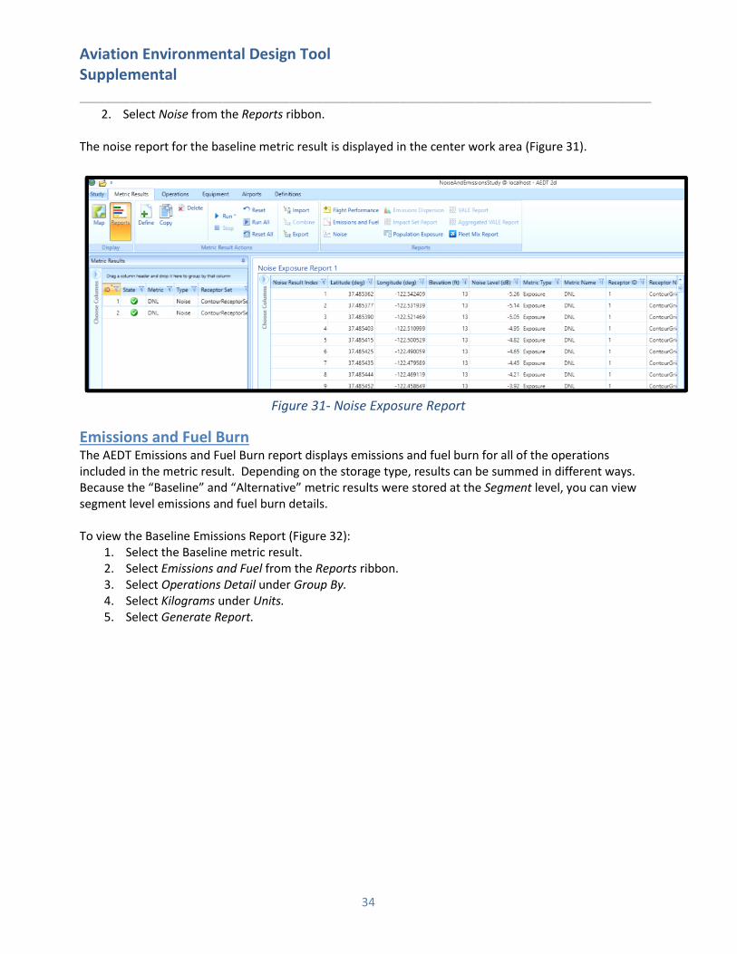
2. Select Noise from the Reports ribbon. The noise report for the baseline metric result is displayed in the center work area (Figure 31).
Figure 31- Noise Exposure Report
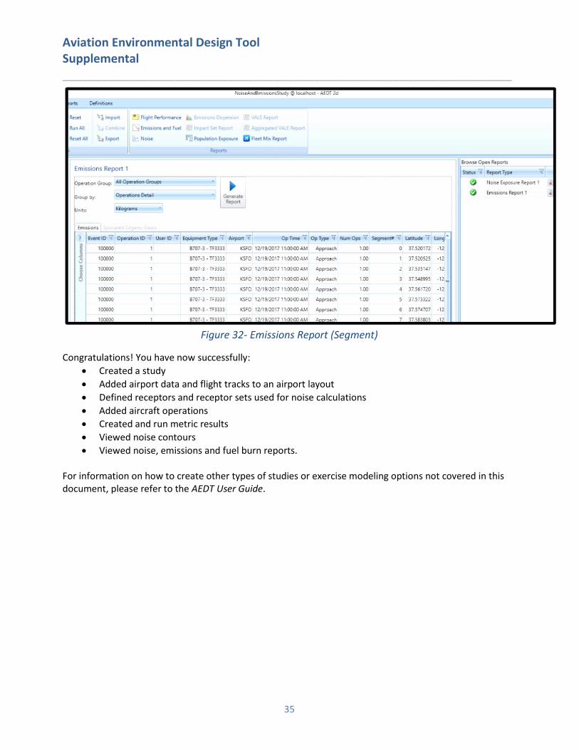
Emissions and Fuel Burn The AEDT Emissions and Fuel Burn report displays emissions and fuel burn for all of the operations included in the metric result. Depending on the storage type, results can be summed in different ways. Because the “Baseline” and “Alternative” metric results were stored at the Segment level, you can view segment level emissions and fuel burn details. To view the Baseline Emissions Report (Figure 32):
1. Select the Baseline metric result. 2. Select Emissions and Fuel from the Reports ribbon. 3. Select Operations Detail under Group By. 4. Select Kilograms under Units. 5. Select Generate Report.
Aviation Environmental Design Tool Supplemental ____________________________________________________________________
35
Figure 32- Emissions Report (Segment)
Congratulations! You have now successfully:
• Created a study
• Added airport data and flight tracks to an airport layout
• Defined receptors and receptor sets used for noise calculations
• Added aircraft operations
• Created and run metric results
• Viewed noise contours
• Viewed noise, emissions and fuel burn reports. For information on how to create other types of studies or exercise modeling options not covered in this document, please refer to the AEDT User Guide.

Aviation Environmental Design Tool Supplemental ____________________________________________________________________
36
Appendix B: Importing EDMS Studies into AEDT AEDT has the ability to import studies directly through the AEDT application or through an external tool. The following sections describe the process for importing EDMS studies in AEDT.
1. AEDT Standard Input File The AEDT Standard Input File (ASIF) provides a standard file format to allow for the import of data into AEDT. Study data is converted to the AEDT Standard Input File (ASIF) as part of the study import process. The ASIF format is based on the XML file format, which is a text-based file format that is readable by both humans and computers.
2. Before You Import As certain EDMS functionality is not yet available in AEDT, there are certain types of data that cannot be imported. Please consult the AEDT User Guide for more information on what functionalities are available. The following four EDMS study data are placed into an ASIF, but not imported into a study:
• Parking Facilities,
• Roadways,
• Discrete Polar Receptors, and
• Polar Receptor Networks. If the EDMS export file contains internally inconsistent or invalid data elements such as invalid GSE assignments with invalid fuel types or duplicate instances of the DEFAULT operational profile, the converter will generate an ASIF, but the ASIF file may not import into AEDT. The EDMS export file or the ASIF may need to be manually corrected to address the errors.
3. Import the EDMS study through the AEDT Application Follow the instructions below to import your EDMS study: 1. Open the AEDT 2d Application.
2. Click the Study tab and click Import to display the Import Study dialog (Figure 33).
3. Select EDMS from the drop-down menu. • Click the Browse button, navigate to the EDMS study file and select Open. • Specifying the Ops schedule folder or the Alternate equipment map file is optional. If desired,
check the appropriate checkbox and click the Browse button to navigate to the directory. • Select Next.
Figure 33 - Choose study location
If you receive the following message, select Close and then Cancel the import (Figure 34). This message

Aviation Environmental Design Tool Supplemental ____________________________________________________________________
37
indicates errors in the EDMS to ASIF conversion process. Please refer to Appendix B, section 5.1 for guidance on resolving the errors associated with this message.
Figure 34- EDMS to ASIF Error warning
4. The Review study content step displays validation errors if any.
• If the “Bad Data Integrity” message appears, select Cancel (Figure 35). This message indicates errors in validating the XML file based on the EDMS study data. Please refer to Appendix B, section 5.2 for guidance on how to resolve these data errors.
Figure 35- Review study content - bad data integrity
• If the message does not appear, the ASIF Raw tab will display a summary view of the study.
• The Details tab displays a detailed view of the study content, organized by categories.
(Figures 36 and 37)

Aviation Environmental Design Tool Supplemental ____________________________________________________________________
38
Figure 36- review study content - Asif raw
Figure 37- review study content - details
5. The Review data conflicts step displays any conflicts between study airport data and AEDT airport data. (Figure 38) (Note: Latitude/Longitude/Altitude mismatches between EDMS and AEDT airport location data and EDMS airport codes that are not in the AEDT database are identified)
• If no data conflicts are present, AEDT displays “No data conflicts eligible for revision were found”.
• If data conflicts are present, review the conflicts reported under Airport Data Conflicts. AEDT lists each element in conflict along with the study value and the system value. Select the appropriate option under Airport Import Resolution to proceed:
o Import file as is: When selected, the airport data will be imported as defined. o Override mismatched airport data in file with AEDT system data: When selected,
the AEDT system airport data will be used in place of the defined airport data.
• Select Next.
Aviation Environmental Design Tool Supplemental ____________________________________________________________________
39
Figure 38- Review data conflicts
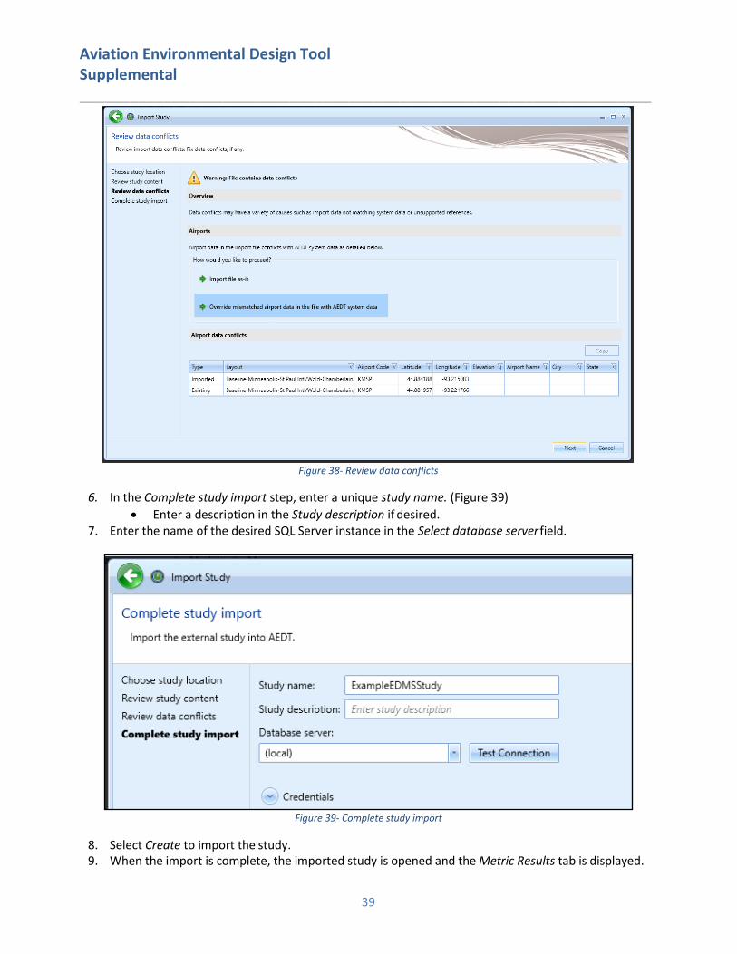
6. In the Complete study import step, enter a unique study name. (Figure 39)
• Enter a description in the Study description if desired. 7. Enter the name of the desired SQL Server instance in the Select database server field.
Figure 39- Complete study import
8. Select Create to import the study. 9. When the import is complete, the imported study is opened and the Metric Results tab is displayed.

Aviation Environmental Design Tool Supplemental ____________________________________________________________________
40
Once imported, update the grid receptor origin according to Section 9.3 in the AEDT 2d User Guide to match the grid definition in the legacy tool.
4. Resolving EDMS to ASIF Import Errors During the EDMS import process, AEDT converts EDMS study data to the ASIF XML format and then validates the XML file before creating the AEDT study in SQL. If your study failed to import, you can refer to the AEDT log file for more information (covered in section 4.9 of the AEDT 2d User Guide). To view system status and logged information, click on the Study tab and click Log. The information shown in the message pane is also written to the aedt.log file in the C:\AEDT\Logs folder. There are two categories of errors: those that occur during the EDMS to ASIF XML conversion and those that occur when validating the XML file created during conversion.
EDMS to ASIF conversion error resolutions are described in Appendix B, section 4.1. If you receive EDMS to ASIF related errors and warnings, you will need to fix the errors in the EDMS study related files and try to import again using the guidance in Appendix B, section 3. ASIF XML validation error resolutions are described in Appendix B, section 4.2. If you receive ASIF XML validation errors, you will need to run the command line EDMS2ASIF program to create an XML file to make your corrections (Appendix B, section 5.1). You will then need to re-import the XML file using the ASIF import guidance in Appendix B, section 5.2. Text in CAPS indicates the study specific data that will be displayed as part of the error message.
4.1. EDMS to ASIF XML Conversion Errors If you encounter errors or warnings during the EDMS to ASIF conversion, you will see a message (Figure 34- EDMS to ASIF Error warning), which displays the number of errors or warnings encountered.
4.1.1. Resolving File Import Errors Import file errors or warnings occur when directories cannot be accessed, files cannot be created, parsed or written. See errors and resolutions below:
1. Error: "EDMS Export Text file FILENAME does not exist.” Resolution: Confirm that the file name input as the EDMS study name (Figure 1) is spelled correctly and exists on the disk.
2. Error: "AircraftSchedule directory DIRECTORYNAME does not exist." Resolution: Confirm that the directory contains the aircraft schedule file (Figure 1) referenced in the EDMS study file and that the directory exists on the disk.
3. Error: "Missing output file name parameter"; Error: "Invalid directory for ASIF output file
DIRECTORYNAME."
Resolution: These errors indicate a problem creating a temporary ASIF file in the AEDT directory: C:\AEDT. Confirm that the directory exists and you have write permissions.
4. Error: "unable to open equipment mapping file 'FILEPATH': "; Error: "error parsing equipment file
'FILEPATH':” ADDITIONALDETAILS
Resolution: Confirm that the directory contains the equipment mapping file (Figure 1) and that the

Aviation Environmental Design Tool Supplemental ____________________________________________________________________
41
file is formatted correctly. Details on formatting errors will be displayed in the error text. 5. Error: "unable to open airports file 'FILEPATH': ADDITIONALDETAILS
Resolution: This is an internal error creating an AEDT airport XML file. Confirm that the directory exists and you have read\write permissions.
6. Error: “Exception thrown by importer: + ADDITIONALDETAILS
Resolution: View additional details for resolution guidance. This error is unlikely to occur.
4.1.2. Resolving EDMS Input Data File Errors (EDMS to ASIF XML) The following errors are due to incorrectly formatted or populated EDMS study files. Guidance for resolving these errors is based on the EDMS 5.1.4 User Manual, Appendix B: Import/Export File Format. The heading of the relevant section precedes the list of errors related to that section, which can be searched in Appendix B of the EDMS User Manual (e.g., PROPERTIES_FOR_SCENARIO-AIRPORT-YEAR_COMBINATIONS):
1. Error: "Unable to find EDMS text file block header, or unrecognized file type"
Resolution: Confirm that the EDMS study file is properly formatted. The study file must contain a header with either “STUDY_HEADER” or “#Study name” or the file type is not valid (TXT). 2. Warning: “Reading unsupported EDMS version: VERSION”.
Resolution: Confirm that the EDMS study is version is 5.1.3, 5.1.4 or 5.1.4.1. Processing will continue.
PROPERTIES_FOR_SCENARIO-AIRPORT-YEAR_COMBINATIONS (Appendix B): 3. Error: "Unable to find AirOperation Schedule file 'FILENAME ' using specified AIRSCHED path
'DIRECTORY’”
Resolution: Confirm that the schedule file exists at the directory specified in the EDMS study file. Resolve airport coordinates 4. Warning: “Unable to find AEDT Airport for runway matching for EDMS airport “AIRPORTCODE”.
Resolution: The warning is logged and processing continues. Airport discrepancies can be resolved by following the mismatched airport guidance during import found in section 2 in this document.
STATIONARY_SOURCES (Appendix B): 5. Error: "expecting only one coordinate for point stationary source: num=#.”
Resolution: Review the file content to make sure only one coordinate is specified and that the text is formatted correctly. 6. Error: "expecting only one coordinate for volume stationary source: num=#.”
Resolution: Review the file content to make sure only one coordinate is specified and that the text is formatted correctly. 7. Error: "unknown stationary source category: CATEGORY.
Resolution: An invalid stationary source category was found (valid categories are 0 – 9). Review the file content to locate the CATEGORY value and enter a valid category.
CONFIGURATION_RUNWAYS (Appendix B): 8. Error: "unable to find airport config [AIRPORTCONFIG] for scen=[SCENARIONAME] and
airport=[AIRPORTNAME]
Resolution: Check the CONFIGURATION_RUNWAYS section of the study file for a valid

Aviation Environmental Design Tool Supplemental ____________________________________________________________________
42
configuration to the scenario/airport combination specified.
QUARTER_HOURLY_PROFILES (Appendix B): 9. Error: "Duplicate quarter hourly profile name >HOURLYPROFILENAME< detected for scenario
SCENARIONAME. “;
10. Error: "Unable to find quarter hourly profile with id HOURLYPROFILENAME for scenario airport
with id AIRPORTID.”
Resolution: Check the study file for duplicate activity profile names and correct them.
MONTHLY_PROFILES (Appendix B): 11. Error: "Duplicate monthly profile name >MONTHLYPROFILENAME< detected for scenario
SCENARIONAME.”
12. Error: "Duplicate daily profile name >DAILYPROFILENAME< detected for scenario
SCENARIONAME.”
Resolution: Check the study file for duplicate activity profile names and correct them.
DAILY_PROFILES (Appendix B): 13. Error: "Unable to find daily profile with id DAILYPROFILENAME for scenario airport with id
AIRPORTID.”
14. Error: "Unable to find monthly profile with id MONTHLYPROFILENAME for scenario airport with id
AIRPORTID".
Resolution: Verify that the activity profiles are linked to the scenario airport identified in the error message.
AIRCRAFT_OPERATIONS (Appendix B): 15. Error: "Unable to find an activity profile for scenario airport with id AIRPORTID because of null or
zero-length operational profile ids".
Resolution: An activity profile is expected but the operational profile id is missing or null. Verify that the profile id is correctly defined as either quarter hour, daily or monthly. 16. Error: “Unable to find air operation EDMS acid for scen_aprt_id='SCENARIOAIRPORTID', airop
line='AIROPLINENUMBER'” Resolution: Incorrect aircraft definition. Refer to the file line number for corrections.
17. Error: "Exception reading AirOperations file 'FILENAME '.”
Resolution: Verify that the file exists on disk. Confirm that the file is formatted correctly.
4.2. Resolving Data Integrity Errors (ASIF XML Validation) The following errors are due to incorrectly populated XML data based on the EDMS study files. They are grouped by the XML section that is being validated. The red text next to the error group refers to the element hierarchy that must be updated. Details on the structure of the elements are found in the AEDT Standard Input File ASIF Reference Guide section 6, however, the high-level element diagrams have been recreated here (where practical) (Figures 40 and 41, for example). Note that additional error information is included in the messages, such as the scenario and case name, which identifies the specific element of the XML that triggered the error or warning. For certain elements, such as scenarios, the references are also validated (e.g., the element case has an element reference that

Aviation Environmental Design Tool Supplemental ____________________________________________________________________
43
contains a reference scenario). Some errors have been grouped if the resolution is the same for each error in the set (e.g., “Duplicate name” is resolved by editing with a unique name).
Figure 40- ASIF xml
Aviation Environmental Design Tool Supplemental ____________________________________________________________________
44
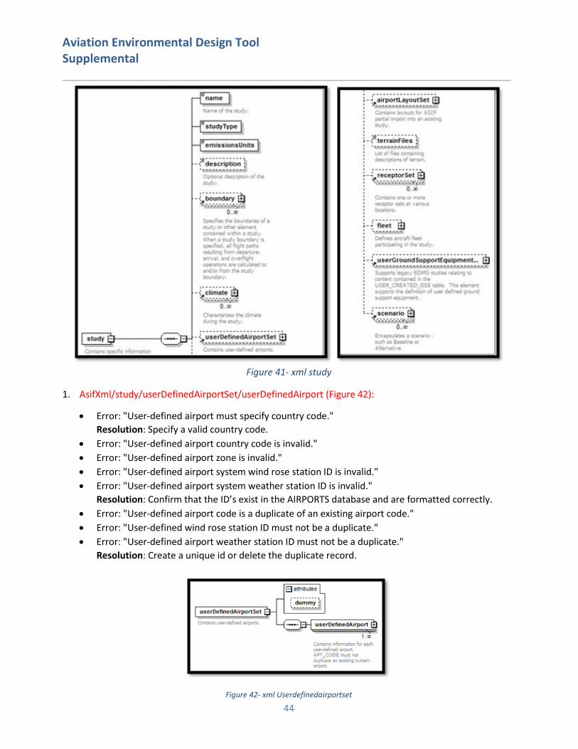
Figure 41- xml study
1. AsifXml/study/userDefinedAirportSet/userDefinedAirport (Figure 42):
• Error: "User-defined airport must specify country code."
Resolution: Specify a valid country code.
• Error: "User-defined airport country code is invalid."
• Error: "User-defined airport zone is invalid."
• Error: "User-defined airport system wind rose station ID is invalid."
• Error: "User-defined airport system weather station ID is invalid."
Resolution: Confirm that the ID’s exist in the AIRPORTS database and are formatted correctly.
• Error: "User-defined airport code is a duplicate of an existing airport code."
• Error: "User-defined wind rose station ID must not be a duplicate."
• Error: "User-defined airport weather station ID must not be a duplicate."
Resolution: Create a unique id or delete the duplicate record.
Figure 42- xml Userdefinedairportset
Aviation Environmental Design Tool Supplemental ____________________________________________________________________
45
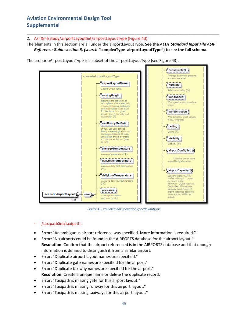
2. AsifXml/study/airportLayoutSet/airportLayoutType (Figure 43):
The elements in this section are all under the airportLayoutType. See the AEDT Standard Input File ASIF Reference Guide section 6, (search “complexType airportLayoutType”) to see the full schema.
The scenarioAirportLayoutType is a subset of the airportLayoutType (see Figure 43).
Figure 43- xml element scenarioairportlayouttype
- /taxipathSet/taxipath:
• Error: "An ambiguous airport reference was specified. More information is required."
• Error: "No airports could be found in the AIRPORTS database for the airport layout."
Resolution: Confirm that the airport referenced is in the AIRPORTS database and that enough
information is defined to distinguish it from a similar airport.
• Error: "Duplicate airport layout names are specified."
• Error: "Duplicate gate names are specified for the airport."
• Error: "Duplicate taxiway names are specified for the airport."
Resolution: Create a unique name or delete the duplicate record.
• Error: "Taxipath is missing gate for this airport layout."
• Error: "Taxipath is missing runway for this airport layout."
• Error: "Taxipath is missing taxiways for this airport layout."

Aviation Environmental Design Tool Supplemental ____________________________________________________________________
46
Resolution: Defined the missing data.
• Error: "Taxipath contains empty taxiway name for this airport layout."
• Error: "Taxipath contains unknown taxiway for this airport layout."
• Error: "Taxipath contains unknown gate for this airport layout."
• Error: "Taxipath contains unknown runway for this airport layout."
Resolution: The taxipath element contains data that is not found in the airport layout. Check the
airport layout in the EDMS study to make sure all elements are correctly listed in the taxipath
element
- /activityProfileSet/activityProfile; - /monthlyProfileSet/monthlyProfile; - /quarterHourlyProfileSet/quarterHourlyProfile; - /dailyProfileSet/dailyProfile:
• Error: "Referenced quarter hourly operational profile in activity operational profile does not exist
within the airport layout"
• Error: "Referenced daily operational profile in activity operational profile does not exist within the
airport layout"
• Error: "Referenced monthly operational profile in activity operational profile does not exist within
the airport layout"
Resolution: Check that the airport layout contains a reference to your profile. If not, add the
appropriate data to the layout or delete the profile.
• Error: "Duplicate quarter hourly operational profile name specified for this airport layout."
• Error: "Duplicate daily operational profile name specified for this airport layout."
• Error: "Duplicate monthly operational profile name specified for this airport layout."
• Error: "Duplicate activity operational profile name specified for this airport layout."
Resolution: Create a unique profile name.
- /stationarySourceSet/ stationarySource
• Error: "A duplicate stationary source name was specified."
Resolution: Create a unique stationary source name.
• Error: "Unknown engine code was specified."
Resolution: Specify a valid engine code.
• Error: "An error in fuel tank choice element was specified."
• Error: "An error in deicing area choice element was specified."
• Error: "An error in boiler/heater choice element was specified."
• Error: "An error in generator choice element was specified."
Resolution: Refer to the EDMS 5.1.4 User Manual for valid element choices.
3. AsifXml/study/airportConfigurationSet/airportConfiguration
• Error: "Duplicate Airport Configuration Name. Multiple airport configurations with the same name
are defined within an airport layout.”
• Error: "Duplicate Scenario Airport Configuration Runway Assignment. “
Resolution: Create unique names or delete duplicate records.
• Error: "Airport configuration's start wind angle is less than its ending wind angle.”
• Error: "Airport configuration's max wind speed is less than its min wind angle.”

Aviation Environmental Design Tool Supplemental ____________________________________________________________________
47
• Error: "Airport configuration's start hour is less than its end hour.”
• Error: "Airport configuration's max ceiling is less than its min ceiling.”
• Error: "Airport configuration's max visibility is less than its min visibility.”
• Error: "Airport configuration's max temperature is less than its min temperature.”
Resolution: Confirm that the range of elements is valid (i.e., maximum cannot be less than the
minimum”).
• Error: "Unknown Runway for Scenario Airport Configuration Runway Assignment. “
Resolution: Create or define a valid runway assignment.
4. AsifXml/study/userGroundSupportEquipment
• Error: "A duplicate user-defined GSE name was specified."
• Error: "A wrong user-defined GSE ID was specified (1 to 44 reserved for system GSE)."
• Error: "A duplicate user-defined GSE id was specified."
Resolution: Create unique names or delete duplicate records.
5. AsifXml/study/receptorSet
• Error: "A duplicate receptor set name was specified."
Resolution: Specify a unique receptor set name.
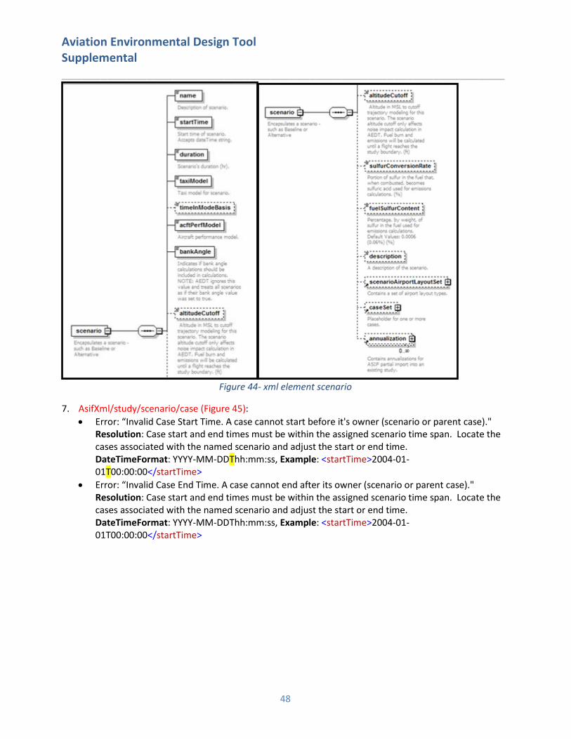
6. AsifXml/study/scenario (Figure 44):
• Error: “A duplicate scenario name was specified." Resolution: Review and correct the scenario names assigned to the scenario elements.
• Error: “Unknown Scenario Airport Layout. The specified airport layout defined for the scenario has not be defined for the study."
Resolution: Define and populate the airport layout in the specified scenario airport layout record.
• Error: “Duplicate Scenario Airport Reference. Multiple layouts which reference the same airport are defined within a scenario."
Resolution: Delete the duplicate airport layout or rename as appropriate.
Aviation Environmental Design Tool Supplemental ____________________________________________________________________
48
Figure 44- xml element scenario
7. AsifXml/study/scenario/case (Figure 45):
• Error: “Invalid Case Start Time. A case cannot start before it's owner (scenario or parent case)." Resolution: Case start and end times must be within the assigned scenario time span. Locate the
cases associated with the named scenario and adjust the start or end time. DateTimeFormat: YYYY-MM-DDThh:mm:ss, Example: <startTime>2004-01-
01T00:00:00</startTime>
• Error: “Invalid Case End Time. A case cannot end after its owner (scenario or parent case)." Resolution: Case start and end times must be within the assigned scenario time span. Locate the
cases associated with the named scenario and adjust the start or end time. DateTimeFormat: YYYY-MM-DDThh:mm:ss, Example: <startTime>2004-01-
01T00:00:00</startTime>

Aviation Environmental Design Tool Supplemental ____________________________________________________________________
49
\ Figure 45- XML element case
8. AsifXml/study/scenario/case/reference (Figure 46):
• Error: “Parent scenario does not exist." Resolution: Make sure the parent scenario is defined and valid in the XML scenario element under
the reference element in the case.
• Error: “Referenced scenario does not exist." Resolution: Make sure the referenced scenario is defined and valid in the XML scenario element
under the reference element in the case.
• Error: “Referenced case does not exist for reference scenario." Resolution: Make sure the referenced case exists (refCase) in the referenced scenario
(refScenario) is defined and valid in the XML reference element.

Aviation Environmental Design Tool Supplemental ____________________________________________________________________
50
• Error: “Referenced case name is a duplicate of an existing case name in parent scenario." Resolution: Make sure the referenced case exists (refCase) in the referenced scenario
(refScenario) is defined and valid in the XML reference element.
• Error: “Parent scenario has missing airport layouts." Resolution: Verify that the parent scenario is linked to a valid airport layout (refScenario).
• Error: “Case name matches scenario name." Resolution: Enter unique names for the reference case and scenario.
• Error: “A duplicate case name was specified for given scenario." Resolution: Enter unique names for the reference cases within the referenced scenario.
Figure 46- reference -> case and scenario
9. AsifXml/trackOpSet/track (Figure 47):
• Error: ”Invalid backbone track, insufficient nodes."
• Error: ”Invalid backbone track. The dispersion weight must be between 0.0 and 1.0."
• Error: “Invalid backbone track. The sum of the dispersion weight(s) must equal 1.0."
Resolution: Dispersion weights represent the percentage of operations assigned to a backbone and subtrack. These must equal 1.0. Individual backbone and subtrack weights must be between 0 and 1 and contain at least two nodes. Confirm that your backbone and subtacks are defined correctly according to these parameters.
• Error: "Track has subtracks with invalid track type"
• Error: "Track has subtracks that does not match the track type"
Resolution: Each subtrack must be of the same type as the backbone track and the valid track types are A (approach), D (departure), V (overflight) and T (touch-and-go). Confirm all of the subtracks are defined correctly.
• Error: "No matching/ambiguous airport code was found for track."
• Error: "Invalid track runway."
• Error: "TrackOpSet has a sensor path with an operation that is missing an arrival or departure
airport."
Resolution: Confirm that any airport and runway references are linked to valid IATA airport codes and runway identifiers.
11. AsifXml/study/scenario/case/trackOpSet (or
AsifXml/study/scenario/case/reference/refcase/trackOpSet)
• Error: "TrackOpSet has no track or sensor paths.”
• Error: "TrackOpSet has no air operation.”
Resolution: Add a valid track, air operation or sensor path.

Aviation Environmental Design Tool Supplemental ____________________________________________________________________
51
12. AsifXml/study/scenario/case/reference/refcase/trackOpSet/track
• Error: "Unknown track reference airport layout."
• Error: "Unknown track reference."
• Error: "Unrecognized aircraft."
• Error: "Unrecognized APU."
Resolution: Define or correct unknown data in the track element.
• Error: "Referenced track does not contain matching track."
• Error: "Referenced track arrival airport does not match arrival operation airport."
• Error: "Referenced track arrival airport runway does not match arrival operation airport runway."
• Error: "Referenced track departure airport does not match departure operation airport."
• Error: "Referenced track departure airport runway does not match departure operation airport
runway."
• Error: "Referenced track arrival airport does not match touch and go operation airport."
• Error: "Referenced track arrival airport runway does not match touch and go operation airport
runway."
• Error: "Referenced track departure airport does not match circuit operation airport."
• Error: "Referenced track departure airport runway does not match circuit operation airport
runway."
• Error: “MESSAGE in
FAA.AEE.AEDT.ASIF.ASIFImporter.AsifStudyValidator.validateAsifTrkOpSetTrackRefAirport(). This
can happen if <arrivalAirport> and <arrivalRunway> are specified for a departure operation; or if
<departureAirport> and <departureRunway> are specified for an arrival operation."
Resolution: The track airport/runways in the trackOpSet/track must match the values referenced
by the case/operations. Correct the mismatched data.
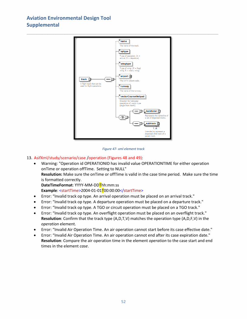
Aviation Environmental Design Tool Supplemental ____________________________________________________________________
52
Figure 47- xml element track
13. AsifXml/study/scenario/case /operation (Figures 48 and 49):
• Warning: "Operation id OPERATIONID has invalid value OPERATIONTIME for either operation onTime or operation offTime. Setting to NULL"
Resolution: Make sure the onTime or offTime is valid in the case time period. Make sure the time is formatted correctly.
DateTimeFormat: YYYY-MM-DDThh:mm:ss Example: <startTime>2004-01-01T00:00:00</startTime>
• Error: “Invalid track op type. An arrival operation must be placed on an arrival track."
• Error: “Invalid track op type. A departure operation must be placed on a departure track."
• Error: “Invalid track op type. A TGO or circuit operation must be placed on a TGO track."
• Error: “Invalid track op type. An overflight operation must be placed on an overflight track." Resolution: Confirm that the track type (A,D,T,V) matches the operation type (A,D,F,V) in the
operation element.
• Error: “Invalid Air Operation Time. An air operation cannot start before its case effective date."
• Error: “Invalid Air Operation Time. An air operation cannot end after its case expiration date." Resolution: Compare the air operation time in the element operation to the case start and end
times in the element case.
diagram
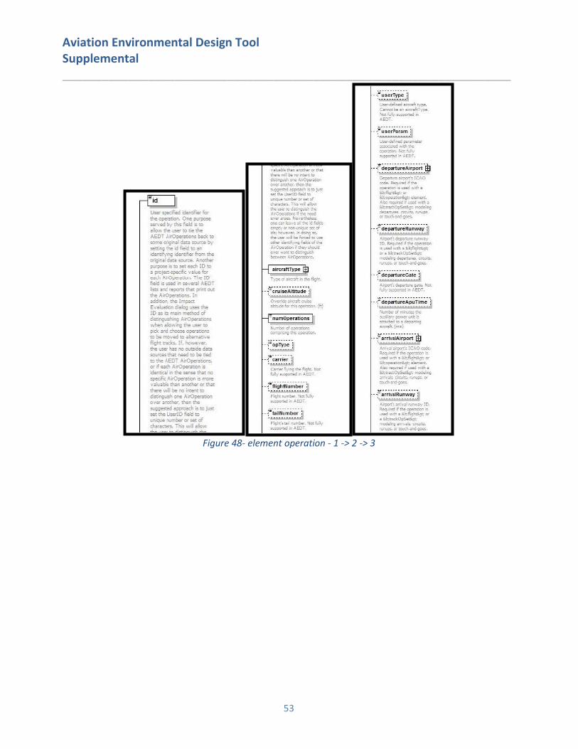
Aviation Environmental Design Tool Supplemental ____________________________________________________________________
53
Figure 48- element operation - 1 -> 2 -> 3
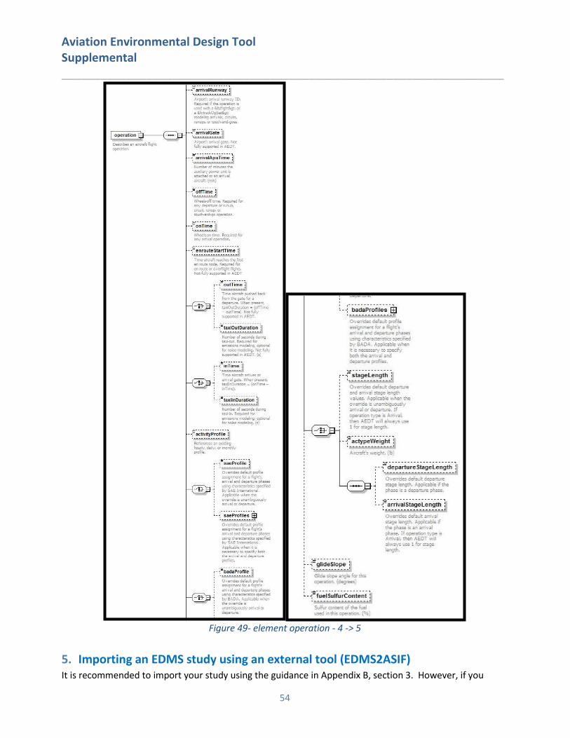
Aviation Environmental Design Tool Supplemental ____________________________________________________________________
54
Figure 49- element operation - 4 -> 5
5. Importing an EDMS study using an external tool (EDMS2ASIF) It is recommended to import your study using the guidance in Appendix B, section 3. However, if you
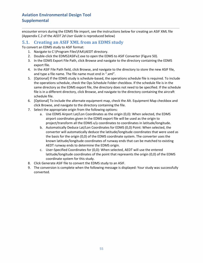
Aviation Environmental Design Tool Supplemental ____________________________________________________________________
55
encounter errors during the EDMS file import, see the instructions below for creating an ASIF XML file (Appendix C.2 of the AEDT 2d User Guide is reproduced below)
5.1. Creating an ASIF XML from an EDMS study To convert an EDMS study to ASIF format:
1. Navigate to C:\Program Files\FAA\AEDT directory. 2. Double-click the EDMS2ASIFv2.exe to open the EDMS to ASIF Converter (Figure 50). 3. In the EDMS Export File Path, click Browse and navigate to the directory containing the EDMS
export file. 4. In the ASIF File Path field, click Browse, and navigate to the directory to store the new ASIF file,
and type a file name. The file name must end in “.xml”. 5. [Optional] If the EDMS study is schedule-based, the operations schedule file is required. To include
the operations schedule, check the Ops Schedule Folder checkbox. If the schedule file is in the same directory as the EDMS export file, the directory does not need to be specified. If the schedule file is in a different directory, click Browse, and navigate to the directory containing the aircraft schedule file.
6. [Optional] To include the alternate equipment map, check the Alt. Equipment Map checkbox and click Browse, and navigate to the directory containing the file.
7. Select the appropriate origin from the following options: a. Use EDMS Airport Lat/Lon Coordinates as the origin (0,0): When selected, the EDMS
airport coordinates given in the EDMS export file will be used as the origin to project/transform all the EDMS x/y coordinates to coordinates in latitude/longitude.
b. Automatically Deduce Lat/Lon Coordinates for EDMS (0,0) Point: When selected, the converter will automatically deduce the latitude/longitude coordinates that were used as the basis for the origin (0,0) of the EDMS coordinate system. The converter uses the known latitude/longitude coordinates of runway ends that can be matched to existing AEDT runway ends to determine the EDMS origin.
c. User-Specified Coordinates for (0,0): When selected, AEDT will use the entered latitude/longitude coordinates of the point that represents the origin (0,0) of the EDMS coordinate system for this study.
8. Click Generate ASIF file to convert the EDMS study to an ASIF. 9. The conversion is complete when the following message is displayed: Your study was successfully
converted.

Aviation Environmental Design Tool Supplemental ____________________________________________________________________
56
Figure 50- EDMS to ASIF
The log file for the EDMS to ASIF Converter is located in the following directory: C:\AEDT\Logs\EDMS2ASIFConverterLog.txt
5.2. Re-importing the ASIF file Once you have corrected the errors in your XML file, you will need to import the file using the ASIF import functionality. You may need to repeat the process outlined below until your XML still contains errors. Follow the instructions below to import your corrected ASIF XML file:
1. Click the Study tab and click Import to display the Import Study dialog.
2. Select ASIF from the drop-down menu. 3. Click the Browse button, navigate to the ASIF file and select Open. Click Next. 4. The Review study content step displays validation errors if any. Click Next. 5. The Review data conflicts step displays any conflicts between study airport data and AEDT
airport data. Click Next. 6. In the Complete study import step, enter a unique study name or accept the default name. 7. Enter the name of the desired SQL Server instance in the Select database server field. 8. Click Create to import the study.
6. Comparing EDMS Results in AEDT After importing your study into AEDT and generating results, you may notice differences in the computed emissions values. This is expected due to the updated algorithms and data in AEDT. However, if you wish to approximate EDMS results in AEDT, the guidance below will help explain expected differences or offer suggestions on minimizing differences between the two models.

Aviation Environmental Design Tool Supplemental ____________________________________________________________________
57
AEDT computes emissions for the full trajectory of each operation, unlike EDMS which computes emissions up to the mixing height. In order to view analogous emissions in AEDT, follow the guidance in section 5.9.2 of the AEDT User Guide for selecting emissions by mode.
6.1. Emissions Methodology Differences
6.1.1. FOA Methodology for Particulate Matter The Committee on Aviation Environmental Protection (CAEP) developed the first-order approximation (FOA) 3.0 methodology to compute particulate matter aircraft engine emissions below a mixing-height. The FOA 3.0A methodology is a modification of FOA 3.0 developed by the Federal Aviation Administration (FAA) and the Environmental Protection Agency (EPA).
• FOA 3.0: Applies to all airports. Sulfur-to-Sulfate Conversion Rate: 2.4 %. Fuel Sulfur Content: 600 ppm.
• FOA 3.0A: Applies to U.S. airports. Sulfur-to-Sulfate Conversion Rate: 5 %. Fuel Sulfur Content: 680
ppm.
EDMS uses FOA 3.0A for U.S airports and FOA 3.0 for airports outside of the U.S. AEDT uses FOA 3.0 exclusively, so differences in particulate matter results are expected.
6.1.2. Particulate Matter Categorization The aircraft emissions module used by EDMS calculates four types of emissions:
• Non-Volatile PM (NVPM): Synonymous with black carbon. AEDT has many more options available
for NVPM calculation than does EDMS.
• Volatile Sulfate PM (PMSO): Computed from fuel sulfur content and sulfur-sulfate conversion rate.
Differs slightly between FOA 3.0 and FOA 3.0A.
• Volatile Fuel Organics (PMFO)
• Volatile Lubrication Oil PM (PMLO): Computed only for climb-out and takeoff flight modes and only
for FOA 3.0A.
EDMS includes PMLO values into the PMFO totals, if any PMLO is actually computed. EDMS sums NVPM, PMSO, and PMFO (including any PMLO) and reports these as both PM10 and PM2.5 for aircraft emissions. AEDT does not include PMLO in PMFO totals. AEDT sums NVPM, PMSO, PMFO, and PMLO and reports this sum as PM10 and PM2.5. AEDT reports three (NVPM, PMFO, and PMSO) of the four parts of PM10/PM2.5. PMLO is not reported separately from PM10/PM2.5.
6.1.3. Airport Weather Airport weather is used to compute both aircraft performance and aircraft emissions results in EDMS and AEDT. Different weather parameters between the EDMS and AEDT databases will lead to performance and emissions differences.
6.2. Aircraft Performance Input Differences
6.2.1. Airport Definition EDMS flight operations can be defined within a study that does not contain any runways. In such a case,
EDMS constructs a default runway with one runway end located at the airport’s location (latitude, longitude, elevation) and with the other runway end at the identical latitude and elevation but with a longitude with an added 0.01°.
Given the many distinct data sources from which analysts can derive airport data, a real-world airport’s
location can be slightly different between AEDT and EDMS. When converting an EDMS study into AEDT, you have the option to use the AEDT database airport data or the EDMS database airport. By selecting

Aviation Environmental Design Tool Supplemental ____________________________________________________________________
58
Import file as-is, the EDMS airport definition will be retained.
6.2.2. Single-Airport Weather When annual average weather is used in EDMS, a flight operation’s performance calculations are performed using the annual average weather parameters of the airport to which the flight operation is tied. When annual average weather is used in AEDT, the default setting is to use the annual averages of the nearest study airport to the flight operation being calculated. In AEDT, set the weather fidelity to use single airport (section 5.2.4.3 of the AEDT 2d User Guide). The use of multi-airport weather in AEDT will result in differences due to the averaging of yearly weather data in AEDT.
6.2.3. Bank Angle The EDMS call to the aircraft performance module specifies that bank angle performance corrections not be applied when computing flight performance results for an airplane operation. AEDT applies bank angle corrections to performance computations by default, but allows you to specify whether or not to use bank angle. Since EDMS uses straight ground tracks when computing aircraft performance, bank angle corrections have little effect on performance results. To eliminate the effect of bank angle, uncheck Use Bank Angle in the AEDT User Interface (section 4.11.2 of the AEDT 2d User Guide).
6.2.4. Taxi Time-in-Mode Fuel Flow When the time-in-mode option is selected for determination of taxi times (i.e., when not using delay and sequence computation of taxi times), EDMS (Equation 1) and AEDT (Equation 2) differ slightly as to the fuel flow rate of aircraft engines during taxiing.
𝑓 =𝑈𝐴_𝑅𝑊𝑓_𝐼𝐷 ∗ 1.1 ∗ 𝛿
𝜃3.8 Eq. 1
𝑓 = 𝑈𝐴_𝑅𝑊𝑓_𝐼𝐷 Eq. 2 where
𝑈𝐴_𝑅𝑊𝑓_𝐼𝐷 Unadjusted idle fuel flow rate (kg/s);
𝛿 =𝑝
𝑝𝐼𝑆𝐴,𝑀𝑆𝐿 Pressure ratio (ratio of local pressure and ISA MSL pressure)
𝜃 =𝑇
𝑇𝐼𝑆𝐴,𝑀𝑆𝐿 Temperature ratio (ratio of local temperature and ISA MSL temperature)
6.3. Aircraft Performance Computation Differences
6.3.1. Truncation at Mixing Height EDMS truncates computed flight profile performance results at the mixing height of the scenario-airport pair, AEDT does not and will produce and report emissions for an entire flight. In order to compare results for only the portion of the flight below the mixing height in AEDT, follow the guidance for viewing the AEDT Emissions Report, by mode, in section 5.9.2 of the AEDT 2d User Guide.

Aviation Environmental Design Tool Supplemental ____________________________________________________________________
59
6.3.2. Fuel Flow Rate Computation Methodology For terminal-area operations of the types available in EDMS (i.e., arrival, departure, touch-and-go), AEDT has three different fuel flow rate methodologies available for fuel flow rate and fuel burn computations:
• ANP: Based on ANP thrust-specific fuel consumption (TSFC) coefficients. For terminal-area
operations, this methodology is generally used when ANP TSFC coefficients are available for an
operation’s ANP aircraft.
• BADA: Based on BADA fuel coefficients. For terminal area operations, this methodology is used
when the ANP methodology could not be used (e.g., due to the unavailability ANP TSFC
coefficients).
• BFFM2: Based on ICAO engine unadjusted fuel flow rate coefficients. This methodology is used
when neither the ANP nor the BADA methodology could be used to determine fuel flow rates and
fuel burn.
EDMS uses the BADA methodology for fuel flow rate and fuel burn computations, except in certain instances where BFFM2 is used (when ANP and BADA cannot be used to determine fuel flow). Since AEDT’s preferred methodology for terminal-area fuel flow (ANP) is not the single fuel flow rate methodology available to EDMS (BADA), it is possible for analogous EDMS and AEDT aircraft operations to use different methodologies for fuel flow rate computations.
6.4. EDMS vs AEDT Database Differences The AEDT database contains several parameters that have been updated according to more recent ICAO standards. Where possible, you may create user defined versions of aircraft using the partial import functionality to allow you to match the relevant data in AEDT to your EDMS study. Differences between the two databases have been noted for certain aircraft parameters including:
1. Unadjusted Fuel Flow Rate
2. Total Hydrocarbon Raw Indices
3. Smoke Number
4. Mixed Turbo-Fan & Bypass Ratio
5. BADA Fuel Coefficients

Aviation Environmental Design Tool Supplemental ____________________________________________________________________
60
Appendix C: Importing an INM study AEDT has the ability to import studies directly through the AEDT application or through an external tool. The following sections describe the process for importing INM studies in AEDT.
1. AEDT Standard Input File The AEDT Standard Input File (ASIF) provides a standard file format to allow for the import of data into AEDT. Study data is converted to the AEDT Standard Input File (ASIF) as part of the study import process. The ASIF format is based on the XML file format, which is a text-based file format that is readable by both humans and computers.
2. Before You Import AEDT can generally import INM studies if the study is valid in the INM 7.0d software program. However, there are several things to verify or correct before you attempt to import your study:
1. AEDT does not process noise grids using the recursive grid functionality as in INM. AEDT will
automatically define all INM contour grids as fixed grids. Please see section 4.11.7 in the AEDT 2b
User Guide for information on the dynamic grid functionality that has replaced INM recursive grids.
2. You must run each scenario in your INM study to generate contours. The importer reads data
from the operations data (ops_calc.dbf) which is generated when processing data for a scenario
run.
3. The conversion of user defined aircraft and profiles in INM studies are not supported and may require extra user actions. The INM to ASIF Converter will populate the <aircraft> element with stub data that will cause ASIF import to fail. It will also populate the <anpAirplane> element data to include flaps, thrust, and profiles. Once an INM study has been converted to ASIF, you must edit the converted study to either replace the INM user defined aircraft with a system AEDT aircraft, or create new user defined AEDT aircraft. See section 3 for information about how to correct the XML file.
4. Airport codes in the converted ASIF file may need to be manually updated to the standard AEDT airport codes in order to be successfully imported into AEDT.
5. Annualizations are not imported into AEDT but can be partially imported at a later time. 6. INM studies can contain incomplete study data. The following INM elements will be skipped if
they are missing data:
a. Tracks without track segments b. Noise identifiers without NPD curves c. Aircraft profiles without steps or procedures
3. Importing an INM Study in the AEDT Application Follow the instructions below to import your INM study:
1. Open the AEDT Application.
2. Click the Study tab and click Import to display the Import Study dialog (Figure 51).
3. Select INM from the drop-down menu. • Click the Browse button, navigate to the INM study file and select Open. • Select Next.
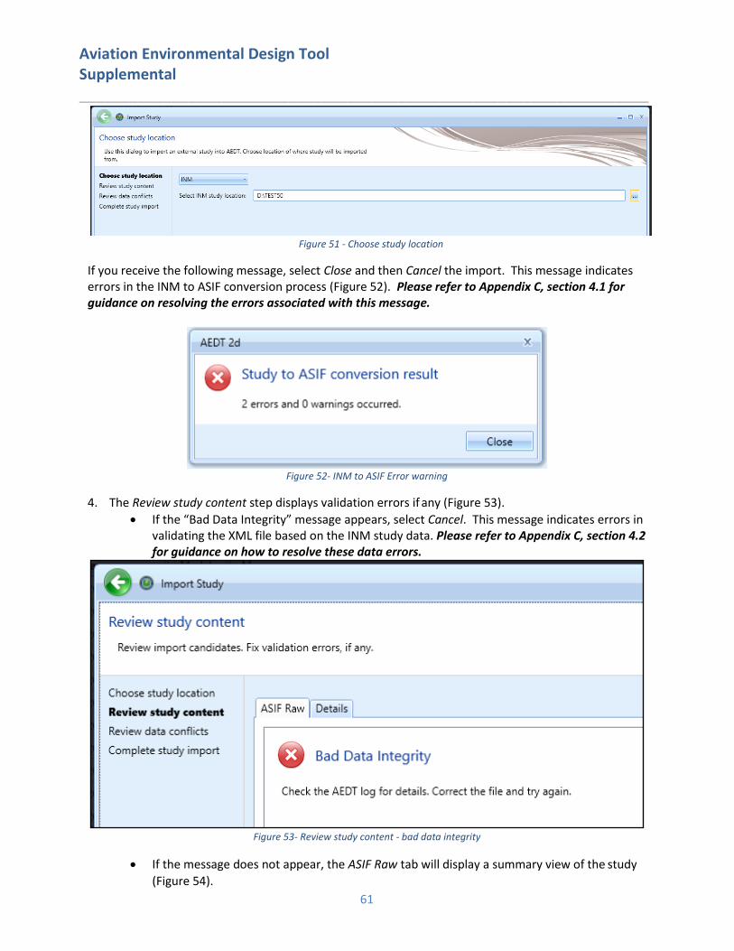
Aviation Environmental Design Tool Supplemental ____________________________________________________________________
61
Figure 51 - Choose study location
If you receive the following message, select Close and then Cancel the import. This message indicates errors in the INM to ASIF conversion process (Figure 52). Please refer to Appendix C, section 4.1 for guidance on resolving the errors associated with this message.
Figure 52- INM to ASIF Error warning
4. The Review study content step displays validation errors if any (Figure 53).
• If the “Bad Data Integrity” message appears, select Cancel. This message indicates errors in validating the XML file based on the INM study data. Please refer to Appendix C, section 4.2 for guidance on how to resolve these data errors.
Figure 53- Review study content - bad data integrity
• If the message does not appear, the ASIF Raw tab will display a summary view of the study
(Figure 54).
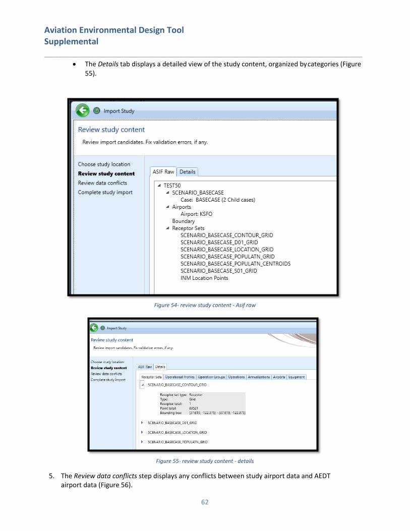
Aviation Environmental Design Tool Supplemental ____________________________________________________________________
62
• The Details tab displays a detailed view of the study content, organized by categories (Figure
55).
Figure 54- review study content - Asif raw
Figure 55- review study content - details
5. The Review data conflicts step displays any conflicts between study airport data and AEDT airport data (Figure 56).
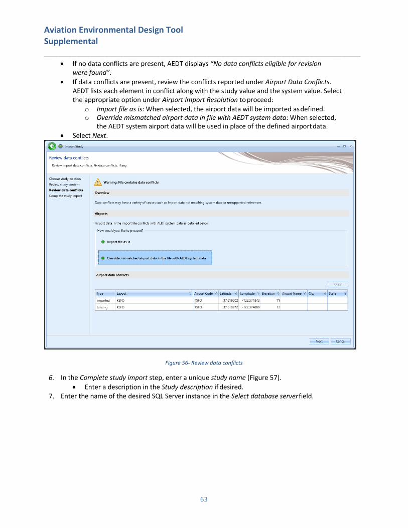
Aviation Environmental Design Tool Supplemental ____________________________________________________________________
63
• If no data conflicts are present, AEDT displays “No data conflicts eligible for revision were found”.
• If data conflicts are present, review the conflicts reported under Airport Data Conflicts. AEDT lists each element in conflict along with the study value and the system value. Select the appropriate option under Airport Import Resolution to proceed:
o Import file as is: When selected, the airport data will be imported as defined. o Override mismatched airport data in file with AEDT system data: When selected,
the AEDT system airport data will be used in place of the defined airport data.
• Select Next.
Figure 56- Review data conflicts
6. In the Complete study import step, enter a unique study name (Figure 57).
• Enter a description in the Study description if desired. 7. Enter the name of the desired SQL Server instance in the Select database server field.

Aviation Environmental Design Tool Supplemental ____________________________________________________________________
64
Figure 57- Complete study import
8. Select Create to import the study. 9. When the import is complete, the imported study is opened and the Metric Results tab is displayed.
Once imported, update the grid receptor origin according to Section 9.3 in the AEDT 2d User Guide to match the grid definition in the legacy tool.
4. Resolving Import Errors During the INM import process, AEDT converts INM study data to the ASIF XML format and then validates the XML file before creating the AEDT study in SQL. If your study failed to import, you can refer to the AEDT log file for more information (covered in section 4.9 of the AEDT User Guide). To view system status and logged information, click on the Study tab and click Log. The information shown in the message pane is also written to the aedt.log file in the C:\AEDT\Logs folder. There are two categories of errors: those that occur during the INM to ASIF XML conversion and those that occur when validating the XML file created during conversion. INM to ASIF conversion error resolutions are described in Appendix C, section 4.1. If you receive INM to ASIF related errors and warnings, you will need to fix the errors in the INM study related files and try to import again using the guidance in Appendix C, section 5.2. ASIF XML validation error resolutions are described in section 4.2. If you receive ASIF XML validation errors, you will need to run the command line INM2ASIF program to create an XML file to make your corrections (See Appendix C.1 of the AEDT User Guide for instructions on how to run the tool). You will then need to re-import the XML file using the ASIF import guidance in Appendix C, section 5.2. Text in CAPS indicates the study specific data that will be displayed as part of the error message.
4.1. INM to ASIF XML Conversion Errors If you encounter errors or warnings during the INM to ASIF conversion, you will see a message (Figure 2- INM to ASIF Error warning), which displays the number of errors or warnings encountered.
4.1.1. Resolving File Import Errors Import file errors or warnings occur when directories cannot be accessed, files cannot be created, parsed or written. See errors and resolutions below:
Aviation Environmental Design Tool Supplemental ____________________________________________________________________
65
Invalid directory or missing files: 1. "Conversion halted. Invalid directory for INM study ' DIRECTORYPATH '."
2. "Conversion halted. Directory DIRECTORYPATH does not contain an INM study (missing
study.inm)."
3. "Invalid INM study folder specified. Unable to open study file 'STUDYINMFILEPATH'."
4. "Invalid INM study folder specified. Unable to open study file ‘STUDYCSVFILEPATH'."
Resolution: Confirm that the directory input exists on disk and that the study.inm and study.csv files exist in the directory. Make sure the files are not opened in another application. Unable to open files:
1. "Unable to open aircraft file 'aircraft.dbf'."
2. "Unable to open aircraft substitution file 'acft_sub.dbf'."
3. "Unable to open nois grp file 'nois_grp.dbf'."
4. "Unable to open NPD curve file 'npd_curv.dbf'."
5. "Unable to open profile file ‘profile.dbf '."
6. "Unable to open procedure file 'procedur.dbf'."
7. "Unable to open profile file 'profile.dbf'."
8. "Unable to open profile points file 'prof_pts.dbf'."
9. "Unable to open flaps file 'flaps.dbf'."
10. "Unable to open thr_jet file 'thr_jet.dbf'."
11. "Unable to open thr_prop file 'thr_prop.dbf'."
12. "Unable to open thr_gnrl file 'thr_gnrl.dbf'."
13. "Unable to open runway file 'runway.dbf'."
14. "Unable to open runway end file 'rwy_end.dbf'."
15. "Unable to open grid file 'grid.dbf'."
16. "Unable to open population points file 'pop_pts.dbf'."
17. "Unable to open location points file 'loc_pts.dbf'."
18. "Unable to open scenario file 'scenario.dbf'."
19. "Unable to open scenario cases file 'scen_par.dbf'."
20. "Unable to open ops calc file 'ops_calc.dbf'."
21. "Unable to open rnup calc file 'ops_rnup.dbf'."
22. "Unable to open track file 'track.dbf'."
23. "Unable to open track segments file 'trk_segs.dbf'."
24. "Unable to open ops calc file 'ops_calc.dbf'."
25. "Unable to open ops rnup file 'ops_rnup.dbf'."
26. "Unable to open track file track.dbf."
27. "Unable to open track segments file trk_segs.dbf."
Resolution: Critical INM study files cannot be accessed. Confirm that the files exist in the directory specified in the import and that you can open them (using Excel). Confirm that the files are not opened by another process.
4.1.2. Resolving INM Input Data File Errors (INM to ASIF XML) The following errors are due to incorrectly formatted or populated INM study files. Guidance for resolving
these errors is based on the INM 7.0d User Guide, Appendix E.

Aviation Environmental Design Tool Supplemental ____________________________________________________________________
66
Errors reading aircraft data: 1. "Unable to query acft_sub data."
Resolution: Confirm that the acft_sub.dbf data exists if the aircraft is defined in the ops_calc.dbf file.
2. "Error occurred while aircraft data. + MESSAGE"
Resolution: This error occurs due to unanticipated problems parsing the aircraft.dbf file. The MESSAGE should provide additional data on how to resolve.
3. "Unable to query aircraft."
Resolution: Confirm that the aircraft.dbf data exists if the aircraft is defined in the ops_calc.dbf file.
4. "Unable to add ANP airplane 'AIRPLANENAME' because it references a bad noise id
'NOISEIDENTIFIER'."
Resolution: The noise identifier linked to the airplane is invalid. This can occur when a user has edited the INM study aircraft.dbf file. Locate the invalid record in the INM aircraft.dbf file and modify the noise identifier to a valid one.
Errors reading profile data:
5. “Error occurred while reading profile data. + MESSAGE"
Resolution: This error occurs due to unanticipated problems parsing the profile.dbf file. The MESSAGE should provide additional data on how to resolve.
6. "Unable to query profile data."
Resolution: Confirm that the profile.dbf data exists for the aircraft/profile combination as defined in the ops_calc.dbf file.
7. "Error occurred while reading procedure step data. + MESSAGE"
Resolution: This error occurs due to unanticipated problems parsing the profile.dbf file. The MESSAGE should provide additional data on how to resolve.
8. "Unable to query procedure step data."
Resolution: Confirm that the procedur.dbf data exists if profile data is defined in the profile.dbf file.
Errors reading noise data:
9. "Error occurred while reading noise group data: MESSAGE"
Resolution: This error occurs due to unanticipated problems parsing the nois_grp.dbf file. The MESSAGE should provide additional data on how to resolve.
10. "Unable to query noise group data."
Resolution: Confirm that the nois_grp.dbf data exists if the noise identifier is used by aircraft in the aircraft.dbf file.
11. "Error occurred while reading noise curve data for noise id 'NOISEID': MESSAGE"
Resolution: This error occurs due to unanticipated problems parsing the npd_curv.dbf file. The MESSAGE should provide additional data on how to resolve.
12. "Unable to query noise curve data for noise id 'NOISEID'."
Resolution: Confirm that the npd_curv.dbf data exists if the noise data is defined in the nois_grp.dbf file.
Errors reading case data:
13. "Error occurred while reading case data. + MESSAGE"
Aviation Environmental Design Tool Supplemental ____________________________________________________________________
67
Resolution: This error occurs due to unanticipated problems parsing the case.dbf file. The
MESSAGE should provide additional data on how to resolve.
14. "Unable to query case data."
Resolution: Confirm that the case.dbf file in the INM study is populated.
Errors reading track data: 15. "Unsupported track segment type SEGMENTTYPE in track TRACKNAME subtrack SUBTRACKID."
Resolution: The track segment types are either ‘P’ for Point or ‘V’ for vector. If the track segment is Vector, the types can be either ‘L’ for left or ‘R’ for right turns. Confirm that the trk_segs.dbf file has valid segment types.
4.2. Resolving Data Integrity Errors (ASIF XML Validation) The following errors are due to incorrectly populated XML data based on the INM study DBF files. They are grouped by the XML section that is being validated. The red text next to the error group refers to the element hierarchy that must be updated. Details on the structure of the elements are found in the AEDT Standard Input File ASIF Reference Guide section 6, however, the high-level element diagrams have been recreated here (where practical). (Figures 58 and 59, for example) Note that additional error information is included in the messages, such as the scenario and case name, which identifies the specific element of the XML that triggered the error or warning. For certain elements, such as scenarios, the references are also validated (e.g., the element case has an element reference that contains a reference scenario). Some errors have been grouped if the resolution is the same for each error in the set (e.g., “Duplicate name” is resolved by editing with a unique name).
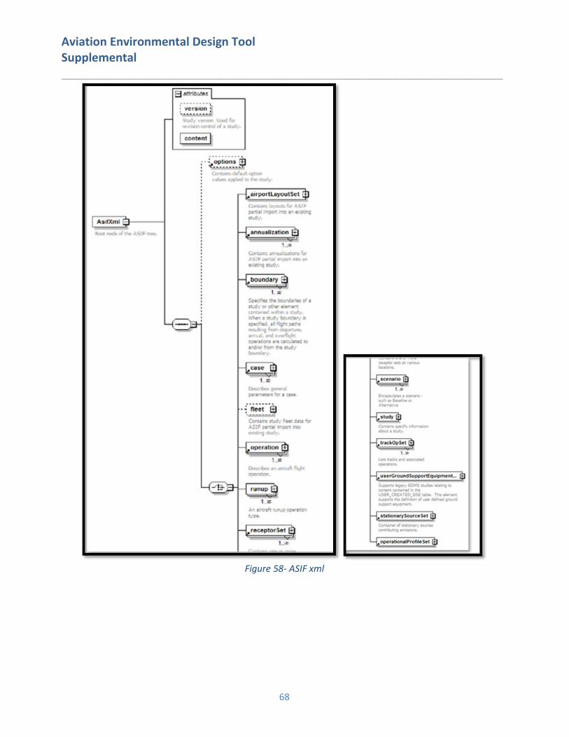
Aviation Environmental Design Tool Supplemental ____________________________________________________________________
68
Figure 58- ASIF xml
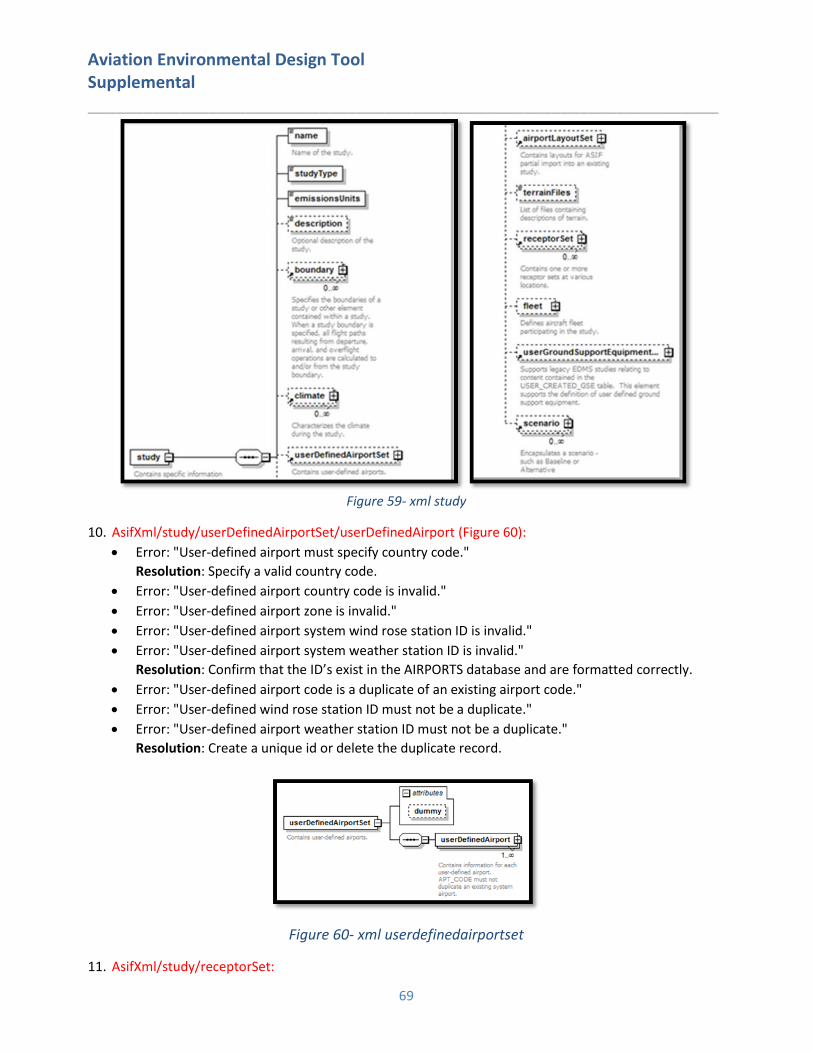
Aviation Environmental Design Tool Supplemental ____________________________________________________________________
69
Figure 59- xml study
10. AsifXml/study/userDefinedAirportSet/userDefinedAirport (Figure 60):
• Error: "User-defined airport must specify country code."
Resolution: Specify a valid country code.
• Error: "User-defined airport country code is invalid."
• Error: "User-defined airport zone is invalid."
• Error: "User-defined airport system wind rose station ID is invalid."
• Error: "User-defined airport system weather station ID is invalid."
Resolution: Confirm that the ID’s exist in the AIRPORTS database and are formatted correctly.
• Error: "User-defined airport code is a duplicate of an existing airport code."
• Error: "User-defined wind rose station ID must not be a duplicate."
• Error: "User-defined airport weather station ID must not be a duplicate."
Resolution: Create a unique id or delete the duplicate record.
Figure 60- xml userdefinedairportset
11. AsifXml/study/receptorSet:

Aviation Environmental Design Tool Supplemental ____________________________________________________________________
70
• Error: "A duplicate receptor set name was specified."
Resolution: Specify a unique receptor set name.
12. AsifXml/study/scenario (Figure 61):
• Error: “A duplicate scenario name was specified." Resolution: Review and correct the scenario names assigned to the scenario elements.
• Error: “Unknown Scenario Airport Layout. The specified airport layout defined for the scenario has not be defined for the study." Resolution: Define and populate the airport layout in the specified scenario airport layout record.
• Error: “Duplicate Scenario Airport Reference. Multiple layouts which reference the same airport are defined within a scenario." Resolution: Delete the duplicate airport layout or rename as appropriate.
Figure 61 - xml element scenario
13. AsifXml/study/scenario/case (Figure 62):
• Error: “Invalid Case Start Time. A case cannot start before it's owner (scenario or parent case)." Resolution: Case start and end times must be within the assigned scenario time span. Locate the cases associated with the named scenario and adjust the start or end time. DateTimeFormat: YYYY-MM-DDThh:mm:ss, Example: <startTime>2004-01-01T00:00:00</startTime>
• Error: “Invalid Case End Time. A case cannot end after its owner (scenario or parent case)." Resolution: Case start and end times must be within the assigned scenario time span. Locate the cases associated with the named scenario and adjust the start or end time. DateTimeFormat: YYYY-MM-DDThh:mm:ss, Example: <startTime>2004-01-
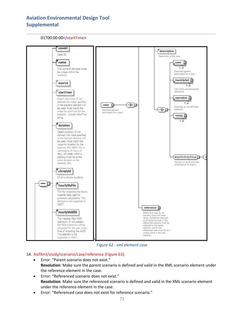
Aviation Environmental Design Tool Supplemental ____________________________________________________________________
71
01T00:00:00</startTime>
\ Figure 62 - xml element case
14. AsifXml/study/scenario/case/reference (Figure 63):
• Error: “Parent scenario does not exist." Resolution: Make sure the parent scenario is defined and valid in the XML scenario element under the reference element in the case.
• Error: “Referenced scenario does not exist." Resolution: Make sure the referenced scenario is defined and valid in the XML scenario element under the reference element in the case.
• Error: “Referenced case does not exist for reference scenario."

Aviation Environmental Design Tool Supplemental ____________________________________________________________________
72
Resolution: Make sure the referenced case exists (refCase) in the referenced scenario (refScenario) is defined and valid in the XML reference element.
• Error: “Referenced case name is a duplicate of an existing case name in parent scenario." Resolution: Make sure the referenced case exists (refCase) in the referenced scenario (refScenario) is defined and valid in the XML reference element.
• Error: “Parent scenario has missing airport layouts." Resolution: Verify that the parent scenario is linked to a valid airport layout (refScenario).
• Error: “Case name matches scenario name." Resolution: Enter unique names for the reference case and scenario.
• Error: “A duplicate case name was specified for given scenario." Resolution: Enter unique names for the reference cases within the referenced scenario.
Figure 63 - reference -> case and scenario
15. AsifXml/trackOpSet/track (Figure 64):
• Error: ”Invalid backbone track, insufficient nodes."
• Error: ”Invalid backbone track. The dispersion weight must be between 0.0 and 1.0."
• Error: “Invalid backbone track. The sum of the dispersion weight(s) must equal 1.0."
Resolution: Dispersion weights represent the percentage of operations assigned to a backbone
and subtrack. These must equal 1.0. Individual backbone and subtrack weights must be between
0 and 1 and contain at least two nodes. Confirm that your backbone and subtacks are defined
correctly according to these parameters.
• Error: "Track has subtracks with invalid track type"
• Error: "Track has subtracks that does not match the track type"
Resolution: Each subtrack must be of the same type as the backbone track and the valid track
types are A (approach), D (departure), V (overflight) and T (touch-and-go). Confirm all of the
subtracks are defined correctly.
• Error: "No matching/ambiguous airport code was found for track."
• Error: "Invalid track runway."
• Error: "TrackOpSet has a sensor path with an operation that is missing an arrival or departure
airport."
Resolution: Confirm that any airport and runway references are linked to valid IATA airport codes
and runway identifiers.
14. AsifXml/study/scenario/case/trackOpSet (or
AsifXml/study/scenario/case/reference/refcase/trackOpSet)
• Error: "TrackOpSet has no track or sensor paths.”
• Error: "TrackOpSet has no air operation.”
Resolution: Add a valid track, air operation or sensor path.
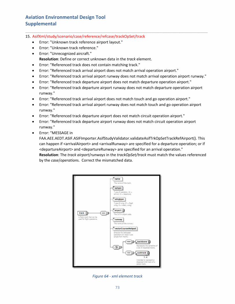
Aviation Environmental Design Tool Supplemental ____________________________________________________________________
73
15. AsifXml/study/scenario/case/reference/refcase/trackOpSet/track
• Error: "Unknown track reference airport layout."
• Error: "Unknown track reference."
• Error: "Unrecognized aircraft."
Resolution: Define or correct unknown data in the track element.
• Error: "Referenced track does not contain matching track."
• Error: "Referenced track arrival airport does not match arrival operation airport."
• Error: "Referenced track arrival airport runway does not match arrival operation airport runway."
• Error: "Referenced track departure airport does not match departure operation airport."
• Error: "Referenced track departure airport runway does not match departure operation airport
runway."
• Error: "Referenced track arrival airport does not match touch and go operation airport."
• Error: "Referenced track arrival airport runway does not match touch and go operation airport
runway."
• Error: "Referenced track departure airport does not match circuit operation airport."
• Error: "Referenced track departure airport runway does not match circuit operation airport
runway."
• Error: “MESSAGE in
FAA.AEE.AEDT.ASIF.ASIFImporter.AsifStudyValidator.validateAsifTrkOpSetTrackRefAirport(). This
can happen if <arrivalAirport> and <arrivalRunway> are specified for a departure operation; or if
<departureAirport> and <departureRunway> are specified for an arrival operation."
Resolution: The track airport/runways in the trackOpSet/track must match the values referenced
by the case/operations. Correct the mismatched data.
Figure 64 - xml element track
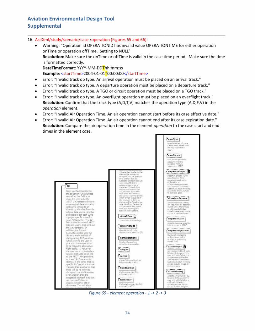
Aviation Environmental Design Tool Supplemental ____________________________________________________________________
74
16. AsifXml/study/scenario/case /operation (Figures 65 and 66):
• Warning: "Operation id OPERATIONID has invalid value OPERATIONTIME for either operation onTime or operation offTime. Setting to NULL" Resolution: Make sure the onTime or offTime is valid in the case time period. Make sure the time is formatted correctly. DateTimeFormat: YYYY-MM-DDThh:mm:ss Example: <startTime>2004-01-01T00:00:00</startTime>
• Error: “Invalid track op type. An arrival operation must be placed on an arrival track."
• Error: “Invalid track op type. A departure operation must be placed on a departure track."
• Error: “Invalid track op type. A TGO or circuit operation must be placed on a TGO track."
• Error: “Invalid track op type. An overflight operation must be placed on an overflight track." Resolution: Confirm that the track type (A,D,T,V) matches the operation type (A,D,F,V) in the operation element.
• Error: “Invalid Air Operation Time. An air operation cannot start before its case effective date."
• Error: “Invalid Air Operation Time. An air operation cannot end after its case expiration date." Resolution: Compare the air operation time in the element operation to the case start and end times in the element case.
Figure 65 - element operation - 1 -> 2 -> 3
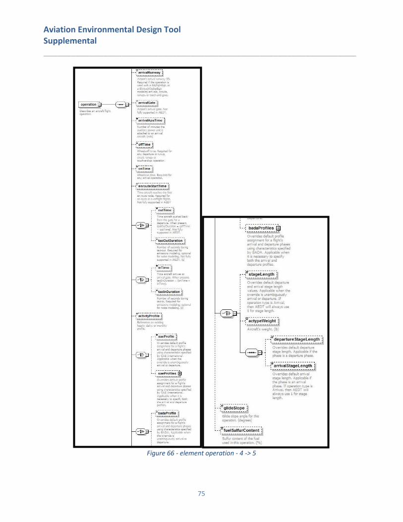
Aviation Environmental Design Tool Supplemental ____________________________________________________________________
75
Figure 66 - element operation - 4 -> 5
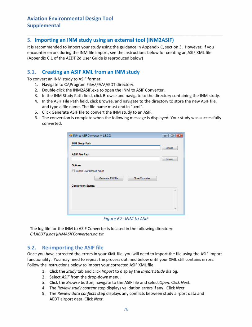
Aviation Environmental Design Tool Supplemental ____________________________________________________________________
76
5. Importing an INM study using an external tool (INM2ASIF) It is recommended to import your study using the guidance in Appendix C, section 3. However, if you encounter errors during the INM file import, see the instructions below for creating an ASIF XML file (Appendix C.1 of the AEDT 2d User Guide is reproduced below)
5.1. Creating an ASIF XML from an INM study To convert an INM study to ASIF format:
1. Navigate to C:\Program Files\FAA\AEDT directory. 2. Double-click the INM2ASIF.exe to open the INM to ASIF Converter. 3. In the INM Study Path field, click Browse and navigate to the directory containing the INM study. 4. In the ASIF File Path field, click Browse, and navigate to the directory to store the new ASIF file,
and type a file name. The file name must end in “.xml”. 5. Click Generate ASIF file to convert the INM study to an ASIF. 6. The conversion is complete when the following message is displayed: Your study was successfully
converted.
Figure 67- INM to ASIF
The log file for the INM to ASIF Converter is located in the following directory: C:\AEDT\Logs\INMASIFConverterLog.txt
5.2. Re-importing the ASIF file Once you have corrected the errors in your XML file, you will need to import the file using the ASIF import functionality. You may need to repeat the process outlined below until your XML still contains errors. Follow the instructions below to import your corrected ASIF XML file:
1. Click the Study tab and click Import to display the Import Study dialog. 2. Select ASIF from the drop-down menu. 3. Click the Browse button, navigate to the ASIF file and select Open. Click Next. 4. The Review study content step displays validation errors if any. Click Next. 5. The Review data conflicts step displays any conflicts between study airport data and
AEDT airport data. Click Next.
Aviation Environmental Design Tool Supplemental ____________________________________________________________________
77
6. In the Complete study import step, enter a unique study name or accept the default name. 7. Enter the name of the desired SQL Server instance in the Select database server field. 8. Click Create to import the study.
6. Comparing INM Results in AEDT After importing your study into AEDT and generating results, you may notice differences in the computed noise values. This is expected due to the updated algorithms and data in AEDT 2d. However, if you wish to approximate INM results in AEDT, the guidance below will help explain expected differences or offer suggestions on minimizing differences between the two models.
6.1. Single-Airport Weather When weather is used in INM, a flight operation’s performance calculations are performed using the weather parameters of the INM study airport. When annual average weather is used in AEDT, the default setting is to use the annual averages of the nearest study airport to the flight operation being calculated. To model weather using the INM parameters, update the Weather data in AEDT (section 5.2.4.3 of the AEDT 2d User Guide) and set the weather fidelity to use single airport weather (section 5.2.4.3 of the AEDT 2d User Guide).
6.2. Bank Angle AEDT applies bank angle corrections to performance computations by default, but allows you to specify whether or not to use bank angle. If you do not wish to use bank angle in AEDT, you can eliminate the effect of bank angle in AEDT by unchecking Use Bank Angle in the AEDT User Interface (section 4.11.2 of the AEDT 2d User Guide). Note that there have been updates to the bank angle algorithm in AEDT which might result in performance differences when bank angle is being compared between models.
6.3. Atmospheric Absorption When defining Metric Results in AEDT, you can select the atmospheric absorption model in the Set Processing Options section of the define metric results (section 5.2.4.4 of the AEDT 2b User Guide):
• Atmospheric absorption type: When selected, AEDT includes the effects of atmospheric absorption on noise according to the selected option: o Unadjusted (SAE-AIR-1845 atmosphere): AEDT uses the atmospheric absorption according
to SAE-AIR-1845 and noise data are unadjusted for study-specific atmospherics. o SAE-ARP-866A: noise data are adjusted for temperature and relative humidity values
(study- specific airport conditions) according to the methods specified in SAE-ARP-866A. o SAE-ARP-5534: noise data are adjusted for temperature, relative humidity, and
atmospheric pressure values (study-specific airport conditions) according to the methods specified in SAE- ARP-5534.
This is analogous to the Modify NPD Curves in INM. If you checked the Modify NPD Curves box for your INM case, select SAE-ARP-866A in the Set Processing Options in AEDT. If unchecked, select Unadjusted.


![Parametric Uncertainty Assessment for AEDT · 2017. 9. 9. · [7] US FAA, Aviation Environmental Design Tool (AEDT) Version 2b Beta 8 User Guide, August 2014 [8] EUROCONTROL, Base](https://img.pdfslide.us/doc/110x75/6131286f1ecc515869448ed1/parametric-uncertainty-assessment-for-aedt-2017-9-9-7-us-faa-aviation-environmental.jpg)