Embed Size (px)
Citation preview
Operator’s Manual
Avant® 9600
Digital Pulse Oximeter
0123 English
Nonin® reserves the right to make changes and improvements to this manual and the products it describes at any time, without notice or obligation.
Nonin Medical, Inc.13700 1st Avenue North
Plymouth, Minnesota 55441-5443, USA
+1 (763) 553-9968(800) 356-8874 (USA and Canada)
Fax: +1 (763) 553-7807E-mail: [email protected]
Nonin Medical AB Fibervägen 2
82450 Hudiksvall, Sweden
+46 650 401500 (Europe)Fax: +46 650 401514
E-mail: [email protected]
www.nonin.com
Authorized EC Representative:MPS, Medical Product Service GmbH
Borngasse 20D-35619 Braunfels, Germany
References to “Nonin” in this manual imply Nonin Medical, Inc.
Nonin, PureLight and nVISION are registered trademarks or trademarks of Nonin Medical, Inc. MicroSoft® and Windows® are registered trademarks of Microsoft Corporation.
© 2011 Nonin Medical, Inc.7936-001-02
CAUTION: Federal law (USA) restricts this device to sale by or on the order of a licensed practitioner.
Consult Instructions for Use.
EC REP

Contents
Indications for Use ........................................................................................ 1Contraindications.................................................................................................... 1Warnings ................................................................................................................ 1Cautions ................................................................................................................. 2
Guide to Symbols .......................................................................................... 4
Displays, Indicators, and Controls............................................................... 5%SpO2 Display....................................................................................................... 5Pulse Rate Display ................................................................................................. 5Numeric LEDs ........................................................................................................ 5Indicators and Icons ............................................................................................... 6Front Panel Buttons................................................................................................ 7
Installing the Batteries .................................................................................. 9
Operating the Avant 9600 ........................................................................... 10Factory Default ..................................................................................................... 10User-Defined Defaults .......................................................................................... 10Operator Functions............................................................................................... 11
Basic Functions................................................................................................. 11User-Defined Defaults....................................................................................... 12Advanced Functions ......................................................................................... 12
Option Switches.................................................................................................... 13Nurse Call Feature ............................................................................................... 14
Alarms and Limits........................................................................................ 16High Priority Alarms.............................................................................................. 16Medium Priority Alarms ........................................................................................ 16Watchdog Alarms ................................................................................................. 17Informational Tones.............................................................................................. 17Reviewing Setting and Changing Alarm Limits..................................................... 17
SpO2 and/or Pulse Alarm Limits ....................................................................... 17Pulse and Alarm Volumes................................................................................. 17
Serial Output Rates .............................................................................................. 18Silencing Alarms................................................................................................... 18Recalling Previous Settings.................................................................................. 18Locked and Unlocked Alarms............................................................................... 19Patient Security Mode .......................................................................................... 19
Viewing and Changing Patient Security Mode.................................................. 19Error Codes .......................................................................................................... 20
Clearing Error Codes 06, 08, or 10 ................................................................... 20
Memory and Data Output Features ............................................................ 21Memory Features ................................................................................................. 21Using nVISION Data Management Software ....................................................... 21
i

Contents (Continued)
Serial Patient Data Outputs...................................................................................22Print-on-Demand Output....................................................................................22Real-Time Patient Data Output..........................................................................22
Using with Philips VueLink ....................................................................................23Connecting to the VueLink Module....................................................................23Patient Alarms ...................................................................................................24Equipment Alarms .............................................................................................24
Care and Maintenance .................................................................................26Cleaning the Model 9600 ......................................................................................26
Parts and Accessories.................................................................................27
Troubleshooting ...........................................................................................28
Service, Support, and Warranty..................................................................30Warranty................................................................................................................30
Technical Information ..................................................................................32Manufacturer’s Declaration ...................................................................................32Equipment Response Time...................................................................................36Testing Summary ..................................................................................................37
SpO2 Accuracy Testing .....................................................................................37Pulse Rate Motion Testing.................................................................................37Low Perfusion Testing .......................................................................................37
Specifications ........................................................................................................38Oximeter ............................................................................................................38System...............................................................................................................39Nurse Call ..........................................................................................................40
ii

iii
Figures Figure 1. Avant 9600 Front and Back View................................................................ 5Figure 2. Installing the Batteries................................................................................. 9Figure 3. Monitor Rear View..................................................................................... 15Figure 4. Avant 9600 Connection to Philips Monitor ................................................ 23
iv
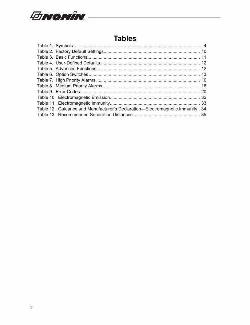
TablesTable 1. Symbols ....................................................................................................... 4Table 2. Factory Default Settings............................................................................. 10Table 3. Basic Functions.......................................................................................... 11Table 4. User-Defined Defaults................................................................................ 12Table 5. Advanced Functions .................................................................................. 12Table 6. Option Switches ......................................................................................... 13Table 7. High Priority Alarms ................................................................................... 16Table 8. Medium Priority Alarms.............................................................................. 16Table 9. Error Codes................................................................................................ 20Table 10. Electromagnetic Emission........................................................................ 32Table 11. Electromagnetic Immunity........................................................................ 33Table 12. Guidance and Manufacturer’s Declaration—Electromagnetic Immunity.. 34Table 13. Recommended Separation Distances ..................................................... 35
Indications for Use
Indications for Use
The Nonin® Avant® 9600 Digital Pulse Oximeter is a portable, tabletop device indicated for use in simultaneously measuring, displaying, and recording functional oxygen saturation of arterial hemoglobin (SpO2) and pulse rate of adult, pediatric, infant, and neonatal patients in hospitals, medical facilities, home care, and subacute environments. It may also be used in patient transport, sleep laboratories, and EMS environments. The Avant 9600 is intended for continuous monitoring and/or spot-checking of patients during both motion and no-motion conditions, and for patients who are well or poorly perfused.
Contraindications
Do not use this device in an MR environment.
This device is not defibrillation proof per IEC 60601-1.
Do not use this device in an explosive atmosphere.
Warnings
This device is intended only as an adjunct in patient assessment. It must be used in conjunction with other methods of assessing clinical signs and symptoms.
The device must be able to measure the pulse properly to obtain an accurate SpO2 measurement. Verify that nothing is hindering the pulse measurement before relying on the SpO2 measurement.
Operation of this device below the minimum amplitude of 0.3% modulation may cause inaccurate results.
General operation of this device may be affected by the use of an electrosurgical unit (ESU).
The use of accessories other than those specified in the Parts and Accessories List may result in increased electromagnetic emission and/or decreased immunity of this device.
This device should not be used adjacent to or stacked with other equipment. If adjacent or stacked use is necessary, the device should be observed carefully to verify normal operation.
Use only Nonin-branded PureLight® pulse oximeter sensors. These sensors are manufactured to meet the accuracy specifications for Nonin pulse oximeters.
Do not use a damaged sensor.
Do not use the device in or around water or any other liquid when the AC power supply is used.
As with all medical equipment, carefully route patient cables and connections to reduce the possibility of entanglement or strangulation.
Use the device only with Nonin-specified power supplies.
The device’s Nurse Call feature should not be used as the primary source of alarm notification.
All parts and accessories connected to the serial port of the device must be certified according to at least IEC 60950 or UL 1950 for data-processing equipment.
1
Indications for Use
The battery pack must be installed at all times while the device is operating, even when operating on AC power. The audible alarms and memory will not function if batteries are removed from the device.
To comply with relevant product safety standards, ensure that all alarm volumes are set appropriately and are audible in all situations.
Cautions
Inspect the sensor application site at least every 6 to 8 hours to ensure correct sensor alignment and skin integrity. Patient sensitivity to sensors may vary due to medical status or skin condition.
This device is designed to determine the percentage of arterial oxygen saturation of functional hemoglobin. Factors that may degrade pulse oximeter performance or affect the accuracy of the measurement include the following:
The device may not work when circulation is reduced. Warm or rub the finger, or reposition the device.
In some circumstances, the device may interpret motion as good pulse quality. Minimize patient motion as much as possible.
Do not autoclave or immerse this device in liquid or use caustic or abrasive cleaning agents.
A functional tester cannot be used to assess the accuracy of a pulse oximeter monitor or sensor.
This equipment complies with IEC 60601-1-2 for electromagnetic compatibility for medical electrical equipment and/or systems. This standard is designed to provide reasonable protection against harmful interference in a typical medical installation. However, because of the proliferation of radio-frequency transmitting equipment and other sources of electrical noise in healthcare and other environments, it is possible that high levels of such interference due to close proximity or strength of a source might disrupt the performance of this device. Medical electrical equipment needs special precautions regarding EMC, and all equipment must be installed and put into service according to the EMC information specified in this manual.
Portable and mobile RF communications equipment can affect medical electrical equipment.
Follow local, state and national governing ordinances and recycling instructions regarding disposal or recycling of the device and device components, including batteries.
In compliance with the European Directive on Waste Electrical and Electronic Equipment (WEEE) 2002/96/EC, do not dispose of this product as unsorted municipal waste. This device contains WEEE materials; please contact your distributor regarding take-back or recycling of the device. If you are unsure how to reach your distributor, please call Nonin for your distributor’s contact information.
If the device fails to respond as described, discontinue use until the situation is corrected by qualified personnel.
Warnings (Continued)
!
- excessive ambient light - excessive motion - electrosurgical interference - blood flow restrictors (arterial catheters, blood
pressure cuffs, infusion lines)- moisture in the sensor - improperly applied sensor - incorrect sensor type
- poor pulse quality- venous pulsations - anemia or low hemoglobin concentrations - cardiogreen and other intravascular dyes - carboxyhemoglobin - methemoglobin - dysfunctional hemoglobin - artificial nails or fingernail polish
2

Indications for Use
When using the 300PS-UNIV power supply, ensure that the AC cord is plugged into a grounded outlet.
To prevent potential loss of monitoring, do not use ear clip or reflective sensors on pediatric or neonatal patients.
This product complies with ISO 10993.
Cautions (Continued)!
3
Guide to Symbols
Guide to Symbols
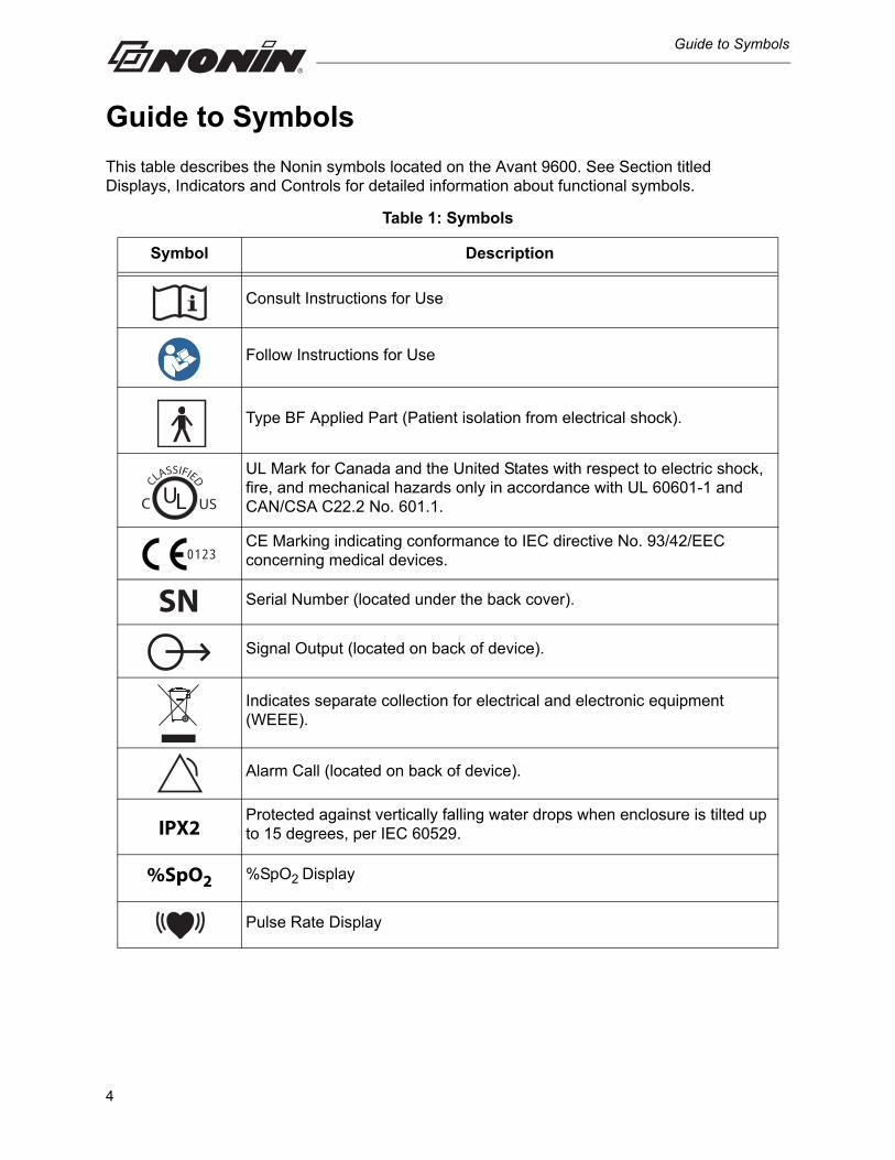
This table describes the Nonin symbols located on the Avant 9600. See Section titled Displays, Indicators and Controls for detailed information about functional symbols.
Table 1: Symbols
Symbol Description
Consult Instructions for Use
Follow Instructions for Use
Type BF Applied Part (Patient isolation from electrical shock).
UL Mark for Canada and the United States with respect to electric shock, fire, and mechanical hazards only in accordance with UL 60601-1 and CAN/CSA C22.2 No. 601.1.
CE Marking indicating conformance to IEC directive No. 93/42/EEC concerning medical devices.
Serial Number (located under the back cover).
Signal Output (located on back of device).
Indicates separate collection for electrical and electronic equipment (WEEE).
Alarm Call (located on back of device).
IPX2Protected against vertically falling water drops when enclosure is tilted up to 15 degrees, per IEC 60529.
%SpO2 %SpO2 Display
Pulse Rate Display
CLASSIFIED
USC UL
0123
SN
4
Displays, Indicators, and Controls
Displays, Indicators, and Controls
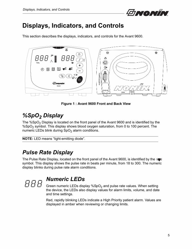
This section describes the displays, indicators, and controls for the Avant 9600.
Figure 1 : Avant 9600 Front and Back View
%SpO2 DisplayThe %SpO2 Display is located on the front panel of the Avant 9600 and is identified by the %SpO2 symbol. This display shows blood oxygen saturation, from 0 to 100 percent. The numeric LEDs blink during SpO2 alarm conditions.
NOTE: LED means “light-emitting diode”.
Pulse Rate DisplayThe Pulse Rate Display, located on the front panel of the Avant 9600, is identified by the symbol. This display shows the pulse rate in beats per minute, from 18 to 300. The numeric display blinks during pulse rate alarm conditions.
Numeric LEDsGreen numeric LEDs display %SpO2 and pulse rate values. When setting the device, the LEDs also display values for alarm limits, volume, and date and time settings.
Red, rapidly blinking LEDs indicate a High Priority patient alarm. Values are displayed in amber when reviewing or changing limits.
9600
5
Displays, Indicators, and Controls
Indicators and Icons
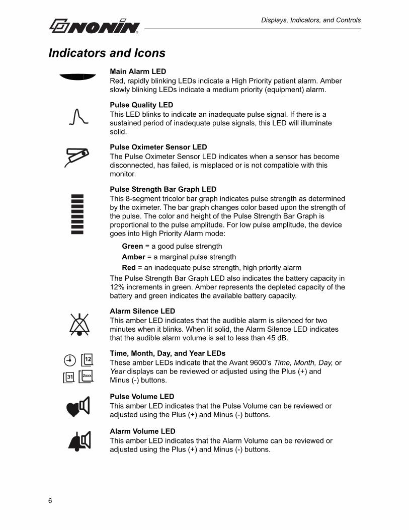
Main Alarm LEDRed, rapidly blinking LEDs indicate a High Priority patient alarm. Amber slowly blinking LEDs indicate a medium priority (equipment) alarm.
Pulse Quality LEDThis LED blinks to indicate an inadequate pulse signal. If there is a sustained period of inadequate pulse signals, this LED will illuminate solid.
Pulse Oximeter Sensor LEDThe Pulse Oximeter Sensor LED indicates when a sensor has become disconnected, has failed, is misplaced or is not compatible with this monitor.
Pulse Strength Bar Graph LEDThis 8-segment tricolor bar graph indicates pulse strength as determined by the oximeter. The bar graph changes color based upon the strength of the pulse. The color and height of the Pulse Strength Bar Graph is proportional to the pulse amplitude. For low pulse amplitude, the device goes into High Priority Alarm mode:
Green = a good pulse strength
Amber = a marginal pulse strength
Red = an inadequate pulse strength, high priority alarm
The Pulse Strength Bar Graph LED also indicates the battery capacity in 12% increments in green. Amber represents the depleted capacity of the battery and green indicates the available battery capacity.
Alarm Silence LEDThis amber LED indicates that the audible alarm is silenced for two minutes when it blinks. When lit solid, the Alarm Silence LED indicates that the audible alarm volume is set to less than 45 dB.
Time, Month, Day, and Year LEDsThese amber LEDs indicate that the Avant 9600’s Time, Month, Day, or Year displays can be reviewed or adjusted using the Plus (+) and Minus (-) buttons.
Pulse Volume LEDThis amber LED indicates that the Pulse Volume can be reviewed or adjusted using the Plus (+) and Minus (-) buttons.
Alarm Volume LEDThis amber LED indicates that the Alarm Volume can be reviewed or adjusted using the Plus (+) and Minus (-) buttons.
6
Displays, Indicators, and Controls
Front Panel Buttons
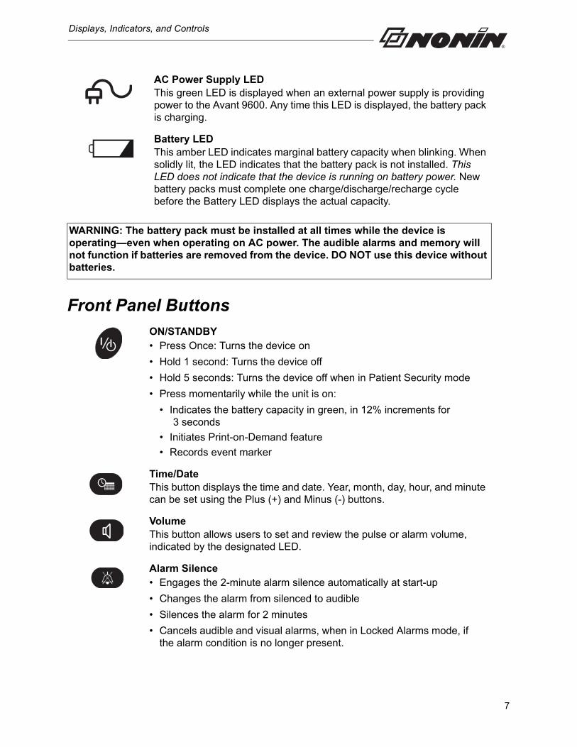
AC Power Supply LED This green LED is displayed when an external power supply is providing power to the Avant 9600. Any time this LED is displayed, the battery pack is charging.
Battery LEDThis amber LED indicates marginal battery capacity when blinking. When solidly lit, the LED indicates that the battery pack is not installed. This LED does not indicate that the device is running on battery power. New battery packs must complete one charge/discharge/recharge cycle before the Battery LED displays the actual capacity.
WARNING: The battery pack must be installed at all times while the device is operating—even when operating on AC power. The audible alarms and memory will not function if batteries are removed from the device. DO NOT use this device without batteries.
ON/STANDBY• Press Once: Turns the device on
• Hold 1 second: Turns the device off
• Hold 5 seconds: Turns the device off when in Patient Security mode
• Press momentarily while the unit is on:
• Indicates the battery capacity in green, in 12% increments for 3 seconds
• Initiates Print-on-Demand feature
• Records event marker
Time/DateThis button displays the time and date. Year, month, day, hour, and minute can be set using the Plus (+) and Minus (-) buttons.
VolumeThis button allows users to set and review the pulse or alarm volume, indicated by the designated LED.
Alarm Silence• Engages the 2-minute alarm silence automatically at start-up
• Changes the alarm from silenced to audible
• Silences the alarm for 2 minutes
• Cancels audible and visual alarms, when in Locked Alarms mode, if the alarm condition is no longer present.
7
Displays, Indicators, and Controls
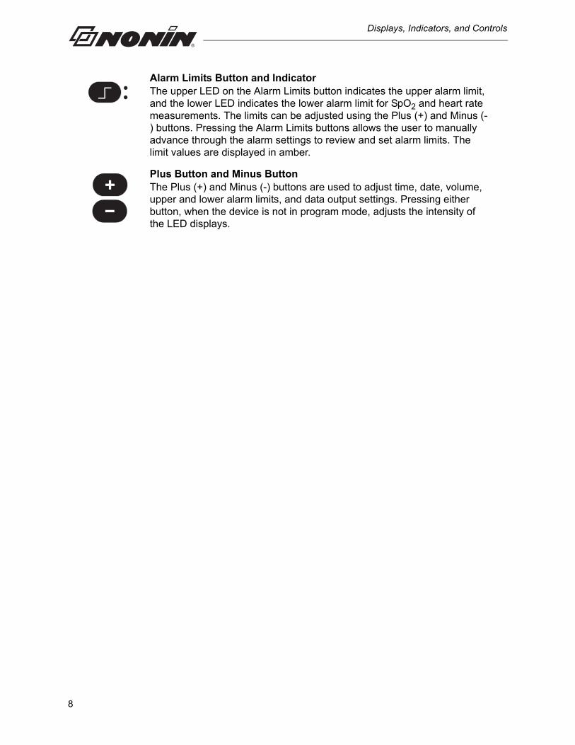
Alarm Limits Button and IndicatorThe upper LED on the Alarm Limits button indicates the upper alarm limit, and the lower LED indicates the lower alarm limit for SpO2 and heart rate measurements. The limits can be adjusted using the Plus (+) and Minus (-) buttons. Pressing the Alarm Limits buttons allows the user to manually advance through the alarm settings to review and set alarm limits. The limit values are displayed in amber.
Plus Button and Minus ButtonThe Plus (+) and Minus (-) buttons are used to adjust time, date, volume, upper and lower alarm limits, and data output settings. Pressing either button, when the device is not in program mode, adjusts the intensity of the LED displays.
8
Installing the Batteries
Installing the Batteries
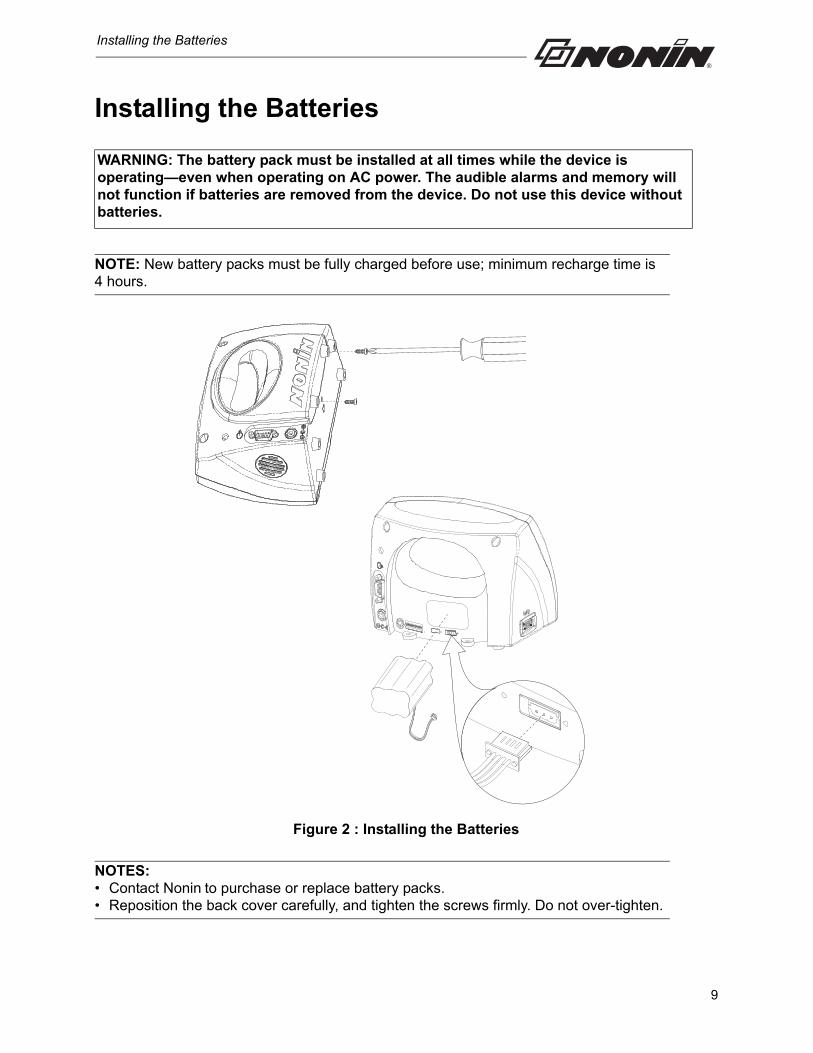
NOTE: New battery packs must be fully charged before use; minimum recharge time is 4 hours.
Figure 2 : Installing the Batteries
NOTES: • Contact Nonin to purchase or replace battery packs.• Reposition the back cover carefully, and tighten the screws firmly. Do not over-tighten.
WARNING: The battery pack must be installed at all times while the device is operating—even when operating on AC power. The audible alarms and memory will not function if batteries are removed from the device. Do not use this device without batteries.
9
Operating the Avant 9600
Operating the Avant 9600
Press the ON/STANDBY button to perform the start-up (initialization) sequence. Verify that all LEDs, except the AC Power Supply LED, are illuminated and the unit beeps three times during the start-up sequence. Contact Nonin Technical Service for assistance.
Use the following procedure to verify that the pulse oximeter sensor is functioning properly.
1. Ensure that the Avant 9600 is on, and the sensor is connected to the monitor.
2. Apply the pulse oximeter sensor to the patient.
3. Verify that SpO2 and pulse rate values are displayed, and the pulse strength bar graph LED is activated.
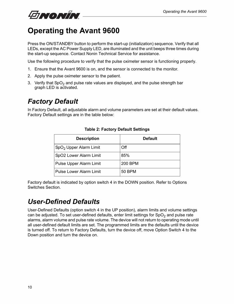
Factory DefaultIn Factory Default, all adjustable alarm and volume parameters are set at their default values. Factory Default settings are in the table below:
Factory default is indicated by option switch 4 in the DOWN position. Refer to Options Switches Section.
User-Defined DefaultsUser-Defined Defaults (option switch 4 in the UP position), alarm limits and volume settings can be adjusted. To set user-defined defaults, enter limit settings for SpO2 and pulse rate alarms, alarm volume and pulse rate volume. The device will not return to operating mode until all user-defined default limits are set. The programmed limits are the defaults until the device is turned off. To return to Factory Defaults, turn the device off, move Option Switch 4 to the Down position and turn the device on.
Table 2: Factory Default Settings
Description Default
SpO2 Upper Alarm Limit Off
SpO2 Lower Alarm Limit 85%
Pulse Upper Alarm Limit 200 BPM
Pulse Lower Alarm Limit 50 BPM
10
Operating the Avant 9600
Operator Functions
Basic Functions
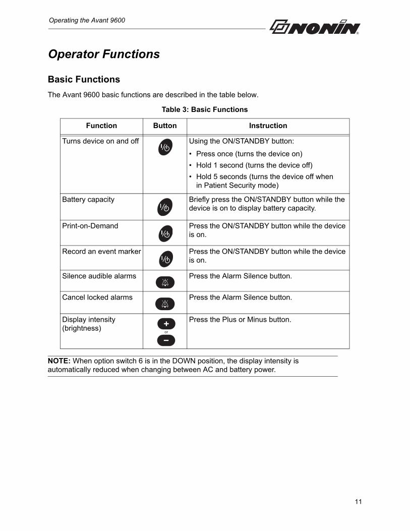
The Avant 9600 basic functions are described in the table below.
NOTE: When option switch 6 is in the DOWN position, the display intensity is automatically reduced when changing between AC and battery power.
Table 3: Basic Functions
Function Button Instruction
Turns device on and off Using the ON/STANDBY button:
• Press once (turns the device on)
• Hold 1 second (turns the device off)
• Hold 5 seconds (turns the device off when in Patient Security mode)
Battery capacity Briefly press the ON/STANDBY button while the device is on to display battery capacity.
Print-on-Demand Press the ON/STANDBY button while the device is on.
Record an event marker Press the ON/STANDBY button while the device is on.
Silence audible alarms Press the Alarm Silence button.
Cancel locked alarms Press the Alarm Silence button.
Display intensity (brightness)
Press the Plus or Minus button.
or
11
Operating the Avant 9600
User-Defined Defaults
Advanced Functions
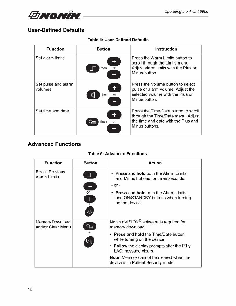
Table 4: User-Defined Defaults
Function Button Instruction
Set alarm limits Press the Alarm Limits button to scroll through the Limits menu. Adjust alarm limits with the Plus or Minus button.
Set pulse and alarm volumes
Press the Volume button to select pulse or alarm volume. Adjust the selected volume with the Plus or Minus button.
Set time and date Press the Time/Date button to scroll through the Time/Date menu. Adjust the time and date with the Plus and Minus buttons.
Table 5: Advanced Functions
Function Button Action
Recall Previous Alarm Limits
• Press and hold both the Alarm Limits and Minus buttons for three seconds.
- or -
• Press and hold both the Alarm Limits and ON/STANDBY buttons when turning on the device.
Memory Download and/or Clear Menu
Nonin nVISION® software is required for memory download.
• Press and hold the Time/Date button while turning on the device.
• Follow the display prompts after the Ply bAC message clears.
Note: Memory cannot be cleared when the device is in Patient Security mode.
orthen
orthen
orthen
+
+
or
+
12
Operating the Avant 9600
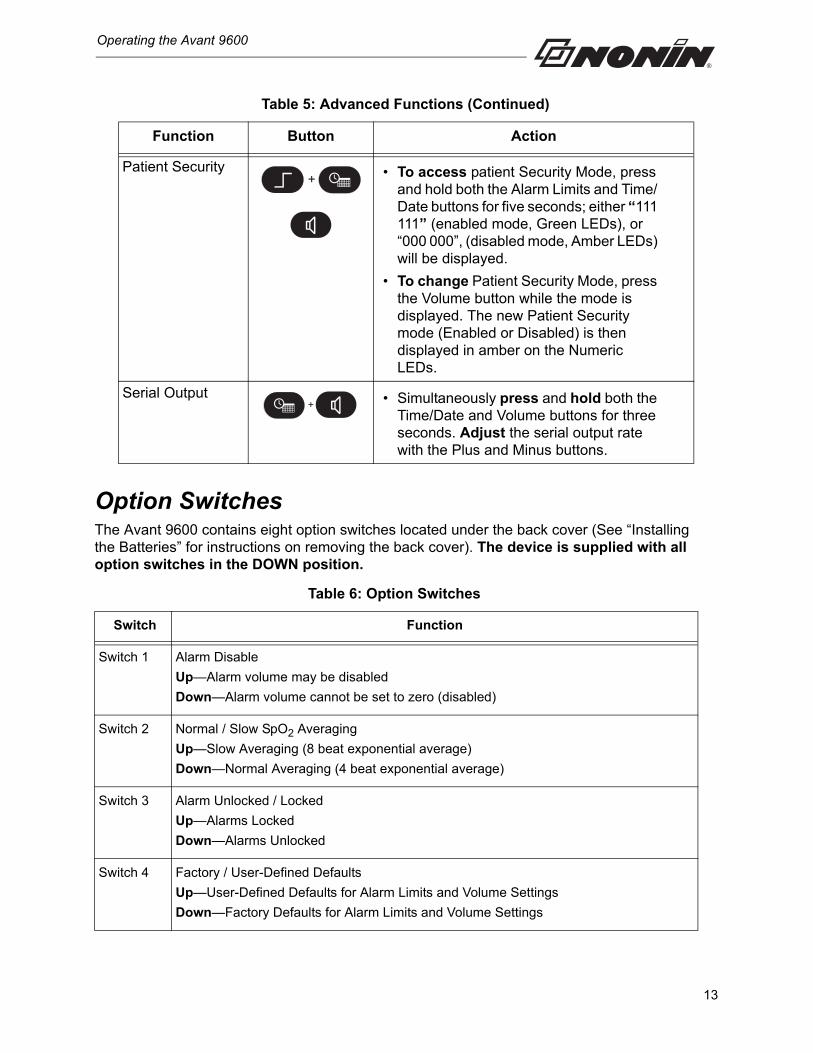
Option SwitchesThe Avant 9600 contains eight option switches located under the back cover (See “Installing the Batteries” for instructions on removing the back cover). The device is supplied with all option switches in the DOWN position.
Patient Security • To access patient Security Mode, press and hold both the Alarm Limits and Time/ Date buttons for five seconds; either “111 111” (enabled mode, Green LEDs), or “000 000”, (disabled mode, Amber LEDs) will be displayed.
• To change Patient Security Mode, press the Volume button while the mode is displayed. The new Patient Security mode (Enabled or Disabled) is then displayed in amber on the Numeric LEDs.
Serial Output • Simultaneously press and hold both the Time/Date and Volume buttons for three seconds. Adjust the serial output rate with the Plus and Minus buttons.
Table 6: Option Switches
Switch Function
Switch 1 Alarm Disable
Up—Alarm volume may be disabled
Down—Alarm volume cannot be set to zero (disabled)
Switch 2 Normal / Slow SpO2 Averaging
Up—Slow Averaging (8 beat exponential average)
Down—Normal Averaging (4 beat exponential average)
Switch 3 Alarm Unlocked / Locked
Up—Alarms Locked
Down—Alarms Unlocked
Switch 4 Factory / User-Defined Defaults
Up—User-Defined Defaults for Alarm Limits and Volume Settings
Down—Factory Defaults for Alarm Limits and Volume Settings
Table 5: Advanced Functions (Continued)
Function Button Action
+
+
13
Operating the Avant 9600
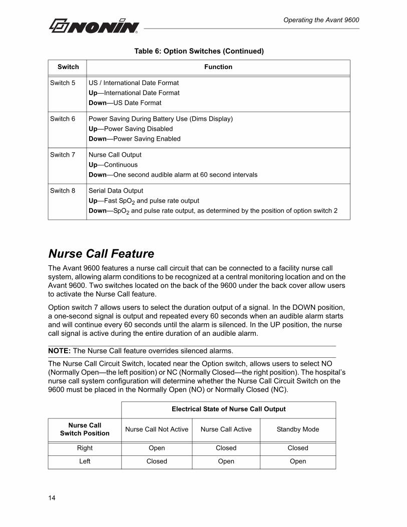
Nurse Call FeatureThe Avant 9600 features a nurse call circuit that can be connected to a facility nurse call system, allowing alarm conditions to be recognized at a central monitoring location and on the Avant 9600. Two switches located on the back of the 9600 under the back cover allow users to activate the Nurse Call feature.
Option switch 7 allows users to select the duration output of a signal. In the DOWN position, a one-second signal is output and repeated every 60 seconds when an audible alarm starts and will continue every 60 seconds until the alarm is silenced. In the UP position, the nurse call signal is active during the entire duration of an audible alarm.
NOTE: The Nurse Call feature overrides silenced alarms.
The Nurse Call Circuit Switch, located near the Option switch, allows users to select NO (Normally Open—the left position) or NC (Normally Closed—the right position). The hospital’s nurse call system configuration will determine whether the Nurse Call Circuit Switch on the 9600 must be placed in the Normally Open (NO) or Normally Closed (NC).
Switch 5 US / International Date Format
Up—International Date Format
Down—US Date Format
Switch 6 Power Saving During Battery Use (Dims Display)
Up—Power Saving Disabled
Down—Power Saving Enabled
Switch 7 Nurse Call Output
Up—Continuous
Down—One second audible alarm at 60 second intervals
Switch 8 Serial Data Output
Up—Fast SpO2 and pulse rate output
Down—SpO2 and pulse rate output, as determined by the position of option switch 2
Electrical State of Nurse Call Output
Nurse CallSwitch Position
Nurse Call Not Active Nurse Call Active Standby Mode
Right Open Closed Closed
Left Closed Open Open
Table 6: Option Switches (Continued)
Switch Function
14
Operating the Avant 9600
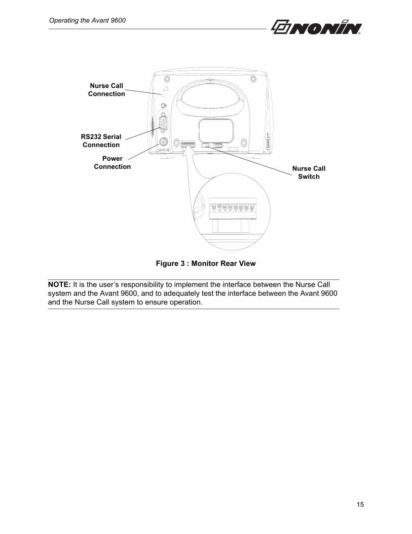
Figure 3 : Monitor Rear View
NOTE: It is the user’s responsibility to implement the interface between the Nurse Call system and the Avant 9600, and to adequately test the interface between the Avant 9600 and the Nurse Call system to ensure operation.
1 2 3 4 5 6 7 8
Nurse Call Connection
RS232 Serial Connection
Power Connection Nurse Call
Switch
15
Alarms and Limits
Alarms and Limits
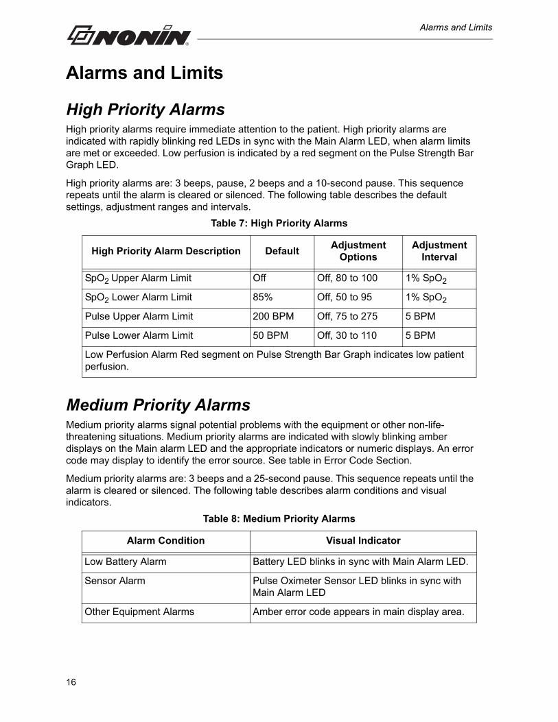
High Priority AlarmsHigh priority alarms require immediate attention to the patient. High priority alarms are indicated with rapidly blinking red LEDs in sync with the Main Alarm LED, when alarm limits are met or exceeded. Low perfusion is indicated by a red segment on the Pulse Strength Bar Graph LED.
High priority alarms are: 3 beeps, pause, 2 beeps and a 10-second pause. This sequence repeats until the alarm is cleared or silenced. The following table describes the default settings, adjustment ranges and intervals.
Medium Priority AlarmsMedium priority alarms signal potential problems with the equipment or other non-life-threatening situations. Medium priority alarms are indicated with slowly blinking amber displays on the Main alarm LED and the appropriate indicators or numeric displays. An error code may display to identify the error source. See table in Error Code Section.
Medium priority alarms are: 3 beeps and a 25-second pause. This sequence repeats until the alarm is cleared or silenced. The following table describes alarm conditions and visual indicators.
Table 7: High Priority Alarms
High Priority Alarm Description DefaultAdjustment
OptionsAdjustment
Interval
SpO2 Upper Alarm Limit Off Off, 80 to 100 1% SpO2
SpO2 Lower Alarm Limit 85% Off, 50 to 95 1% SpO2
Pulse Upper Alarm Limit 200 BPM Off, 75 to 275 5 BPM
Pulse Lower Alarm Limit 50 BPM Off, 30 to 110 5 BPM
Low Perfusion Alarm Red segment on Pulse Strength Bar Graph indicates low patient perfusion.
Table 8: Medium Priority Alarms
Alarm Condition Visual Indicator
Low Battery Alarm Battery LED blinks in sync with Main Alarm LED.
Sensor Alarm Pulse Oximeter Sensor LED blinks in sync with Main Alarm LED
Other Equipment Alarms Amber error code appears in main display area.
16
Alarms and Limits
Watchdog AlarmsWatchdog alarms are loud, two-tone, steadily beeping signals that indicate a hardware or software malfunction. When a watchdog alarm is activated, it can be cleared by shutting down the device. If the watchdog alarm does not clear, remove the battery and contact your distributor or Nonin Technical Service.
Informational TonesInformational tones are at startup/initialization (speaker verification) and the pulse rate tone (which changes in pitch with SpO2 values). They are typically single “beeps” or a series of 3 “beeps.”
Reviewing Setting and Changing Alarm Limits
NOTE: Alarm limits reset themselves to default values each time the device is turned on, unless the device is in Patient Security mode. In Patient Security mode, alarm limits and volumes cannot be adjusted; they can only be viewed.
SpO2 and/or Pulse Alarm Limits
1. Press the Alarm Limits button and check the following:
• The LEDs to the right of the Alarm Limits button are illuminated. The upper LED indicates the upper alarm limit and the lower LED indicates the lower alarm limit.
• The current setting appears in the %SpO2 display.
2. The limits can be adjusted by using the Plus (+) or Minus (-) buttons until the appropriate limits are displayed.
NOTE: The Alarm Limits button allows the user to manually exit this function or you may wait 10 seconds for the device to automatically exit.
Pulse and Alarm Volumes
1. Press the Volume button once to display the current alarm volume, and a second time to display the current pulse volume.
2. Use the Plus (+) or Minus (-) buttons to adjust the alarm or pulse volumes.
NOTE: The volume button allows the user to manually exit this function or you may wait 10 seconds for the device to automatically exit.
17
Alarms and Limits
Serial Output Rates1. Simultaneously press and hold the Time/Date and Volume buttons for 3 seconds.
• Use the Plus or Minus buttons to adjust the serial output to the appropriate rate. The selectable output rates are as follows:
• SEr Pod = Print-on-Demand
• SEr 001 = every second (factory default rate)
• SEr 030 = every 30 seconds
• SEr 060 = every minute
• SEr 300 = every 5 minutes
• SEr 600 = every 10 minutes
• SEr 900 = every 15 minutes
• The Serial mode will exit automatically after 10 seconds with no activity.
NOTE: Each time the device is turned on, the previous serial output rate is retained.
Silencing AlarmsTo silence alarms for two minutes, press the Alarm Silence button.
To permanently silence all alarms, Option Switch 1 must be placed in the UP position. This allows the Alarm Volume to be set to zero. The Alarm Silence LED will remain lit when the alarm volume is set less than 45dB.
Recalling Previous SettingsThe Avant 9600 allows the operator to recall settings in use when the device was turned off:
• SpO2 high and low alarm limits
• Pulse rate high and low alarm limits
• Alarm volume settings
• Informational tone volume settings
Previous user-defined settings can be recalled by either:
• Simultaneously pressing and holding the Alarm Limits and Minus buttons for 3 seconds while the device is on,
or
• By pressing and holding both the Alarm Limits and ON/STANDBY buttons when turning on the device.
WARNING: To comply with relevant product safety standards, ensure that all alarm volumes are set appropriately and are audible in all situations. Do not cover or otherwise hinder any speaker openings.
18
Alarms and Limits
Locked and Unlocked AlarmsThe Avant 9600 allows users to switch between Locked or Unlocked Alarms with Option Switch 3, located under the back cover. Unlocked alarms (Option Switch 3 in the DOWN position) is the default.
When the device is in Unlocked Alarms, the Main Alarm LED and the exceeded alarm value will flash, and the audible alarm will sound until the alarm condition is no longer present.
In Locked Alarms, the audible and visual alarm will continue to signal, until the alarm is cleared or silenced, by pressing the Alarm Silence button.
NOTE: High Priority (Patient Alarms) may be locked or unlocked; Medium Priority (Equipment Alarms) are always unlocked.
Patient Security ModeWhen the Patient Security mode is enabled, users cannot change SpO2 or Pulse Rate limits but it is still possible to view limits. In Patient Security mode, users cannot view or set the alarm volume, pulse volume, time and date, or serial output rate.
When the device is turned on in Patient Security mode, amber “111 111” blinks 3 times on the display, and 3 beeps are sounded. The upper alarm limits are then displayed, followed by the lower alarm limits.
NOTES: • Patient memory cannot be cleared when the device is in Patient Security mode.• Patient Security mode is not disabled when the device is turned off• Patient Security retains limits when the device is turned off.
Viewing and Changing Patient Security Mode
To access patient Security Mode, press and hold both the Alarm Limits and Time/ Date buttons for five seconds; either “111 111” (enabled mode, Green LEDs), or “000 000”, (disabled mode, Amber LEDs) will be displayed.
To change Patient Security Mode, press the Volume button while the mode is displayed. The new Patient Security mode (Enabled or Disabled) is then displayed in amber on the Numeric LEDs.
NOTE: Alarm limits cannot be changed when the device is in Patient Security mode. Patient Security mode prevents accidental changes to critical limits.
19
Alarms and Limits
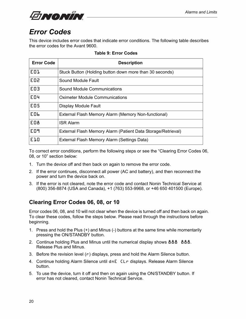
Error CodesThis device includes error codes that indicate error conditions. The following table describes the error codes for the Avant 9600.
To correct error conditions, perform the following steps or see the “Clearing Error Codes 06, 08, or 10” section below:
1. Turn the device off and then back on again to remove the error code.
2. If the error continues, disconnect all power (AC and battery), and then reconnect the power and turn the device back on.
3. If the error is not cleared, note the error code and contact Nonin Technical Service at (800) 356-8874 (USA and Canada), +1 (763) 553-9968, or +46 650 401500 (Europe).
Clearing Error Codes 06, 08, or 10
Error codes 06, 08, and 10 will not clear when the device is turned off and then back on again. To clear these codes, follow the steps below. Please read through the instructions before beginning.
1. Press and hold the Plus (+) and Minus (-) buttons at the same time while momentarily pressing the ON/STANDBY button.
2. Continue holding Plus and Minus until the numerical display shows 888 888. Release Plus and Minus.
3. Before the revision level (r) displays, press and hold the Alarm Silence button.
4. Continue holding Alarm Silence until dnE CLr displays. Release Alarm Silence button.
5. To use the device, turn it off and then on again using the ON/STANDBY button. If error has not cleared, contact Nonin Technical Service.
Table 9: Error Codes
Error Code Description
E01 Stuck Button (Holding button down more than 30 seconds)
E02 Sound Module Fault
E03 Sound Module Communications
E04 Oximeter Module Communications
E05 Display Module Fault
E06 External Flash Memory Alarm (Memory Non-functional)
E08 ISR Alarm
E09 External Flash Memory Alarm (Patient Data Storage/Retrieval)
E10 External Flash Memory Alarm (Settings Data)
20
Memory and Data Output Features
Memory and Data Output Features
Memory FeaturesModel 9600 collects and stores a minimum of 115 hours of SpO2 and pulse rate data.
Data may be downloaded with Nonin’s nVISION data management software.
The memory in the device functions as an “endless loop” tape. When the memory fills up, the device overwrites the oldest data with the new data.
Each time the device is turned on, the current time/date information (if the clock is set properly) is stored in memory, starting a new data collection. Only data collections greater than one minute in length are stored in memory.
Patient SpO2 and pulse rate are sampled every 2 seconds. Every 4 seconds, the high and low values of the 4-second sample period are stored. Oxygen saturation values are stored in 1% increments in a range of 0 to 100%.
The stored pulse rate ranges from 18 to 300 pulses per minute (BPM). The stored values are in increments of 1 pulse per minute in a range of 18 to 200 pulses per minute, and in increments of 2 pulses per minute in a range of 201 to 300 pulses per minute (BPM).
Using nVISION Data Management SoftwareThe Avant 9600 has a Memory Download feature allowing stored data to be transferred to Nonin’s nVISION data management software for analysis. When downloading data, use the following procedure:
1. With the device turned off, attach the null modem cable to the RS232 connector port of the device and to the back of your computer.
2. With the device turned off, simultaneously press and hold the Time/Date button and the ON/STANDBY button. All LEDs will illuminate briefly. PLy bAC will appear in the SpO2 and Pulse Rate display areas. This message indicates the device is now in Download mode.
3. The PLy bAC message will disappear after a few seconds, indicating memory download is complete; larger files might take several minutes. Pressing the ON/STANDBY button will exit Download mode.
4. A CLr no message will be displayed, and 3 beeps will sound.
WARNING: The battery pack must be installed at all times while the device is operating—even when operating on AC power. Do NOT use the device without batteries. The audible alarms and memory will not function if batteries are removed from the device.
21
Memory and Data Output Features
5. Memory CLear (OPTIONAL):
• Simultaneously press and hold the ON/STANDBY button and the Plus (+) button to select CLr yES.
• Press the ON/STANDBY button for the next prompt.
• Use the Plus (+) and/or Minus (-) buttons to select dEL yES if desired.
• Press the ON/STANDBY button for the next prompt.
• dnE CLr confirms that the memory is clear.
6. Press the ON/STANDBY button to return to normal operation.
7. For more information about using nVISION, refer to nVISION’s online help.
NOTES: • Patient memory cannot be cleared when the Avant 9600 is in Patient Security mode.• Selecting yES from the dEL window will permanently delete the device’s memory.
Serial Patient Data OutputsThe Avant 9600 features real-time and Print-on-Demand options. All reports include a header with the model number, time, and date information.
Real-time data output is provided by connecting a null modem cable to the RS232 connector port and the receiving computer. Data is sent in an ASCII serial format at 9600 baud with 8 data bits, 1 start bit, and 2 stop bits; each line is terminated by CR/LF.
Print-on-Demand Output
Avant 9600 allows Print-on-Demand if the system is connected to a printer. This operation is performed by pressing the ON/STANDBY button, as needed. The device features a Print-on-Demand option, allowing users to output data each time the ON/STANDBY button is pressed.
Real-Time Patient Data Output
Data output is sent once per second in one of the following formats:
• If option switch 8 is in the UP position, the data will be displayed as follows:
SPO2=XXX HR=YYY F
where XXX and YYY are the SpO2 and pulse rate values and F signifies “output: fast”.
• If option switch 8 is in the DOWN position, the data will be displayed as follows:
SPO2=XXX HR=YYY
where XXX and YYY are the SpO2 and pulse rate values as selected by option switch 2.
NOTES: • To insert an event marker, press the ON/STANDBY button.• The serial output rate is automatically returned to its previous setting upon device
startup.
22
Memory and Data Output Features
Using with Philips VueLinkThe Avant 9600 supports the Phillips VueLink Open Interface (V.O.I.), and will communicate with a Philips VueLink Auxiliary Plus Type B module (product number M1032A#A05). Refer to the operator’s manual for additional instructions and information.
Connecting to the VueLink Module
The 9600 is connected with the VueLink Module via a Philips cable (product number M1032A#K6C), which connects to the RS-232 Serial Connection on the 9600. The device detects the VueLink connection and begins communication automatically. Disconnecting the cable or turning off the device will stop communications.
When the 9600 is connected to the VueLink module and interfaced to a compatible Philips multiparameter monitor (contact Philips for compatibility), the following data will be sent for display:
• plethysmographic waveform
• SpO2 data, as displayed on the oximeter
• pulse rate data, as displayed on the oximeter
• high and low SpO2 and pulse rate alarm limits
• alarm conditions (for both patient and equipment alarms)
NOTES: • When dashes are displayed for SpO2 or pulse rate data, the oximeter identifies that
data as “not available” to the VueLink module.• Limits set to “off” on the 9600 are reported to the VueLink module as the maximum
values of the upper limits and the minimum values of the lower limits.
A
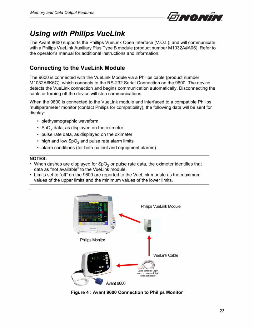
Figure 4 : Avant 9600 Connection to Philips Monitor
Philips VueLink Module
VueLink Cable
Philips Monitor
Avant 9600
Cable contains 12 pin round connector & 9 pin
serial connector
23
Memory and Data Output Features
Patient Alarms
Only one alarm condition can be reported to the VueLink at a time. Because of this, patient alarm conditions are assigned priorities—with only the highest priority alarm displayed at any one time. Alarms are sent to the VueLink even when the oximeter’s alarms are silenced. Alarm priorities are assigned as follows:
a. SpO2 Low Limit
b. Pulse Rate High Limit
c. Pulse Rate Low Limit
d. SpO2 High Limit
e. Low Perfusion
Equipment Alarms
VueLink displays equipment alarms as “inoperatives.” Only one inoperative condition can be reported to the VueLink at a time. Because of this, inoperatives are assigned priorities—with only the highest priority displayed at any one time. Inoperatives are sent to the VueLink even when the oximeter’s alarms are silenced. Inoperative priorities are assigned as follows:
a. No SpO2 Sensor
b. SpO2 Sensor Fault
c. No SpO2 Data
d. No Pulse Data
e. Low Battery
The following text strings, associated with the device, are sent through the VueLink module for display on the multiparameter monitor:
Parameter Displayed Text
Displayed High SpO2 Limit HiSpO2
Displayed Low SpO2 Limit LoSpO2
Displayed High Pulse Rate Limit Hi PR
Displayed Low Pulse Rate Limit Lo PR
SpO2 High Limit Alarm SpO2: HIGH
SpO2 Low Limit Alarm SpO2: LOW
Pulse Rate High Limit Alarm PULSE: HIGH
Pulse Rate Low Limit Alarm PULSE: LOW
Low Perfusion Alarm LOW PERFUSION
Sensor Disconnect NO SpO2 SENSOR
24

Memory and Data Output Features
Sensor Fault SpO2 SENSOR
No SpO2 Data Available NO SpO2 Data
No Pulse Data Available NO Pulse Data
Low Battery Battery: Pulse Ox
Parameter Displayed Text
25
Care and Maintenance
Care and Maintenance
The Avant 9600 requires no calibration or periodic maintenance other than battery replacement.
Do not attempt to open the case or repair the electronics. Opening the case will damage the device and void the warranty. If the device is not functioning properly, see “Troubleshooting.”
Cleaning the Model 9600Clean the Avant 9600 with a soft cloth dampened with isopropyl alcohol. Do not pour or spray any liquids onto the device, and do not allow any liquid to enter any openings in the device. Allow the device to dry thoroughly before reusing it.
Refer to the pulse oximeter sensor Instructions for Use for cleaning information.
CAUTION: Do not autoclave or immerse this device in liquid or use caustic or abrasive cleaning agents.!
26

Parts and Accessories
Parts and Accessories
For more information about Nonin parts and accessories:
• See the Parts and Accessories List on the Operator’s Manual CD.
• Contact your distributor or Nonin at (800) 356-8874 (USA and Canada), +1 (763) 553 9968, or +46 650 401500 (Europe).
• Visit www.nonin.com.
27
Troubleshooting
Troubleshooting
Problem Possible Cause Possible Solution
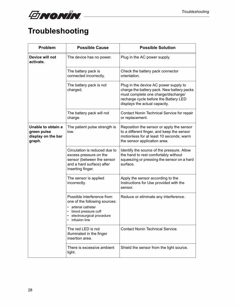
Device will not activate.
The device has no power. Plug in the AC power supply.
The battery pack is connected incorrectly.
Check the battery pack connector orientation.
The battery pack is not charged.
Plug in the device AC power supply to charge the battery pack. New battery packs must complete one charge/discharge/recharge cycle before the Battery LED displays the actual capacity.
The battery pack will not charge.
Contact Nonin Technical Service for repair or replacement.
Unable to obtain a green pulse display on the bar graph.
The patient pulse strength is low.
Reposition the sensor or apply the sensor to a different finger, and keep the sensor motionless for at least 10 seconds; warm the sensor application area.
Circulation is reduced due to excess pressure on the sensor (between the sensor and a hard surface) after inserting finger.
Identify the source of the pressure. Allow the hand to rest comfortably without squeezing or pressing the sensor on a hard surface.
The sensor is applied incorrectly.
Apply the sensor according to the Instructions for Use provided with the sensor.
Possible interference from one of the following sources:
• arterial catheter• blood pressure cuff• electrosurgical procedure• infusion line
Reduce or eliminate any interference.
The red LED is not illuminated in the finger insertion area.
Contact Nonin Technical Service.
There is excessive ambient light.
Shield the sensor from the light source.
28
Troubleshooting
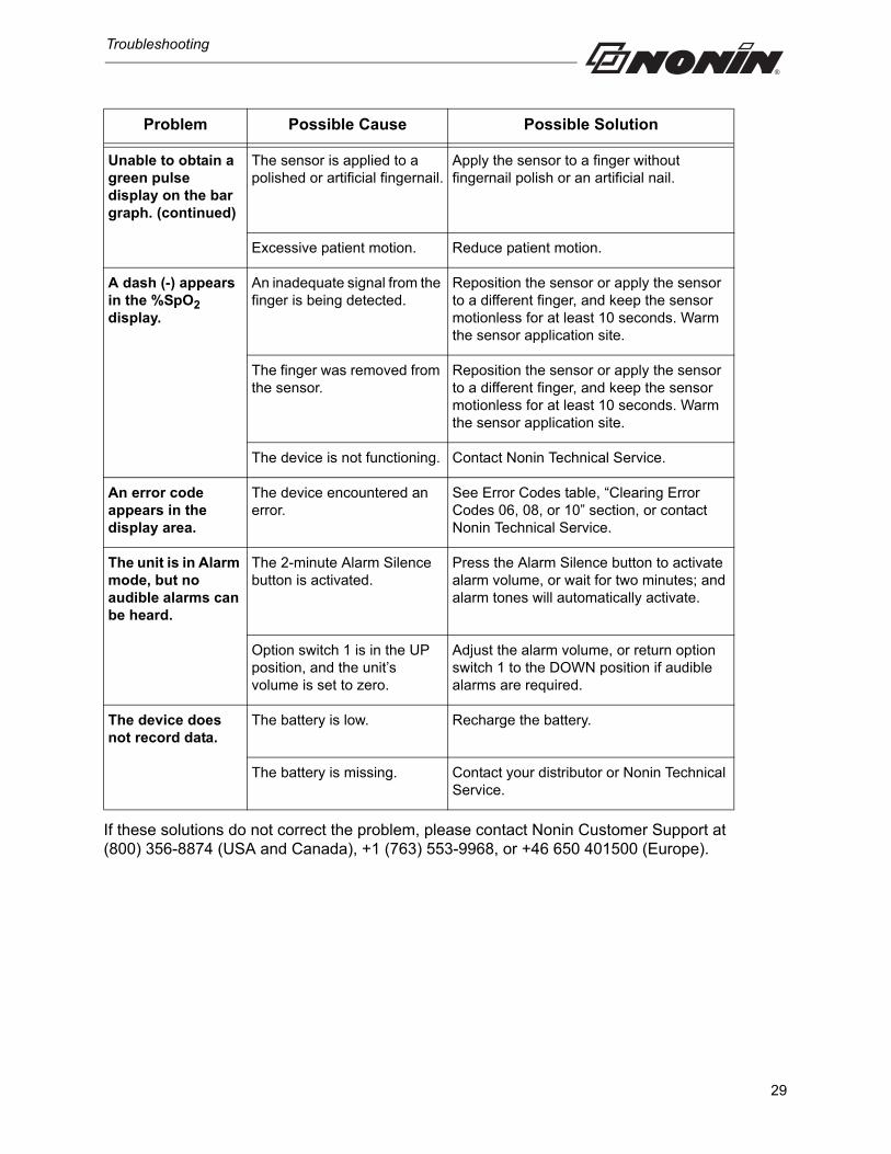
If these solutions do not correct the problem, please contact Nonin Customer Support at (800) 356-8874 (USA and Canada), +1 (763) 553-9968, or +46 650 401500 (Europe).
Unable to obtain a green pulse display on the bar graph. (continued)
The sensor is applied to a polished or artificial fingernail.
Apply the sensor to a finger without fingernail polish or an artificial nail.
Excessive patient motion. Reduce patient motion.
A dash (-) appears in the %SpO2 display.
An inadequate signal from the finger is being detected.
Reposition the sensor or apply the sensor to a different finger, and keep the sensor motionless for at least 10 seconds. Warm the sensor application site.
The finger was removed from the sensor.
Reposition the sensor or apply the sensor to a different finger, and keep the sensor motionless for at least 10 seconds. Warm the sensor application site.
The device is not functioning. Contact Nonin Technical Service.
An error code appears in the display area.
The device encountered an error.
See Error Codes table, “Clearing Error Codes 06, 08, or 10” section, or contact Nonin Technical Service.
The unit is in Alarm mode, but no audible alarms can be heard.
The 2-minute Alarm Silence button is activated.
Press the Alarm Silence button to activate alarm volume, or wait for two minutes; and alarm tones will automatically activate.
Option switch 1 is in the UP position, and the unit’s volume is set to zero.
Adjust the alarm volume, or return option switch 1 to the DOWN position if audible alarms are required.
The device does not record data.
The battery is low. Recharge the battery.
The battery is missing. Contact your distributor or Nonin Technical Service.
Problem Possible Cause Possible Solution
29
Service, Support, and Warranty
Service, Support, and Warranty
A return authorization number is required before returning any product to Nonin. To obtain this return authorization number, contact Nonin Technical Service:
Nonin Medical, Inc.13700 1st Avenue North
Plymouth, Minnesota 55441-5443 USA
(800) 356-8874 (USA and Canada)+1 (763) 553-9968 (outside USA & Canada)
Fax: +1 (763) 553-7807E-mail: [email protected]
Nonin Medical AB Fibervägen 2
82450 Hudiksvall, Sweden
+46 650 401500 (Europe)Fax: +46 650 401514
E-mail: [email protected]
www.nonin.com
WarrantyNONIN MEDICAL, INCORPORATED, (Nonin) warrants to the purchaser, for a period of one year from the date of purchase, each Avant 9600 battery pack. Nonin warrants the pulse oximetry module of the Avant 9600 for a period of three years from the date of purchase. Extended warranties are available on most Nonin pulse oximeter models. Please consult your local Nonin distributor for additional information.
Nonin shall repair or replace any Avant 9600 found to be defective in accordance with this warranty, free of charge, for which Nonin has been notified by the purchaser by serial number that there is a defect, provided said notification occurs within the applicable warranty period. This warranty shall be the sole and exclusive remedy by the purchaser hereunder for any Avant 9600 delivered to the purchaser which is found to be defective in any manner, whether such remedies be in contract, tort, or by law.
This warranty excludes cost of delivery to and from Nonin. All repaired devices shall be received by the purchaser at Nonin's place of business. Nonin reserves the right to charge a fee for a warranty repair request on any Avant 9600 that is found to be within specifications.
The Avant 9600 is a precision electronic instrument and must be repaired by knowledgeable and specially trained Nonin personnel only.
30
Service, Support, and Warranty
Accordingly, any sign or evidence of opening the Avant 9600, field service by non-Nonin personnel, tampering, or any kind of misuse or abuse of the Avant 9600, shall void the warranty in its entirety. All non-warranty work shall be done according to Nonin standard rates and charges in effect at the time of delivery to Nonin.
DISCLAIMER/EXCLUSIVITY OF WARRANTY:
THE EXPRESS WARRANTIES SET FORTH IN THIS MANUAL ARE EXCLUSIVE AND NO OTHER WARRANTIES OF ANY KIND, WHETHER STATUTORY, WRITTEN, ORAL, OR IMPLIED, INCLUDING WARRANTIES OF FITNESS FOR A PARTICULAR PURPOSE OR MERCHANTABILITY, SHALL APPLY.
31
Technical Information
Technical Information
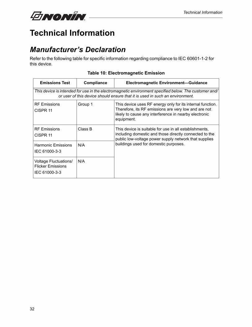
Manufacturer’s DeclarationRefer to the following table for specific information regarding compliance to IEC 60601-1-2 for this device.
Table 10: Electromagnetic Emission
Emissions Test Compliance Electromagnetic Environment—Guidance
This device is intended for use in the electromagnetic environment specified below. The customer and/or user of this device should ensure that it is used in such an environment.
RF Emissions
CISPR 11
Group 1 This device uses RF energy only for its internal function. Therefore, its RF emissions are very low and are not likely to cause any interference in nearby electronic equipment.
RF Emissions
CISPR 11
Class B This device is suitable for use in all establishments, including domestic and those directly connected to the public low-voltage power supply network that supplies buildings used for domestic purposes.Harmonic Emissions
IEC 61000-3-3
N/A
Voltage Fluctuations/Flicker Emissions
IEC 61000-3-3
N/A
32
Technical Information
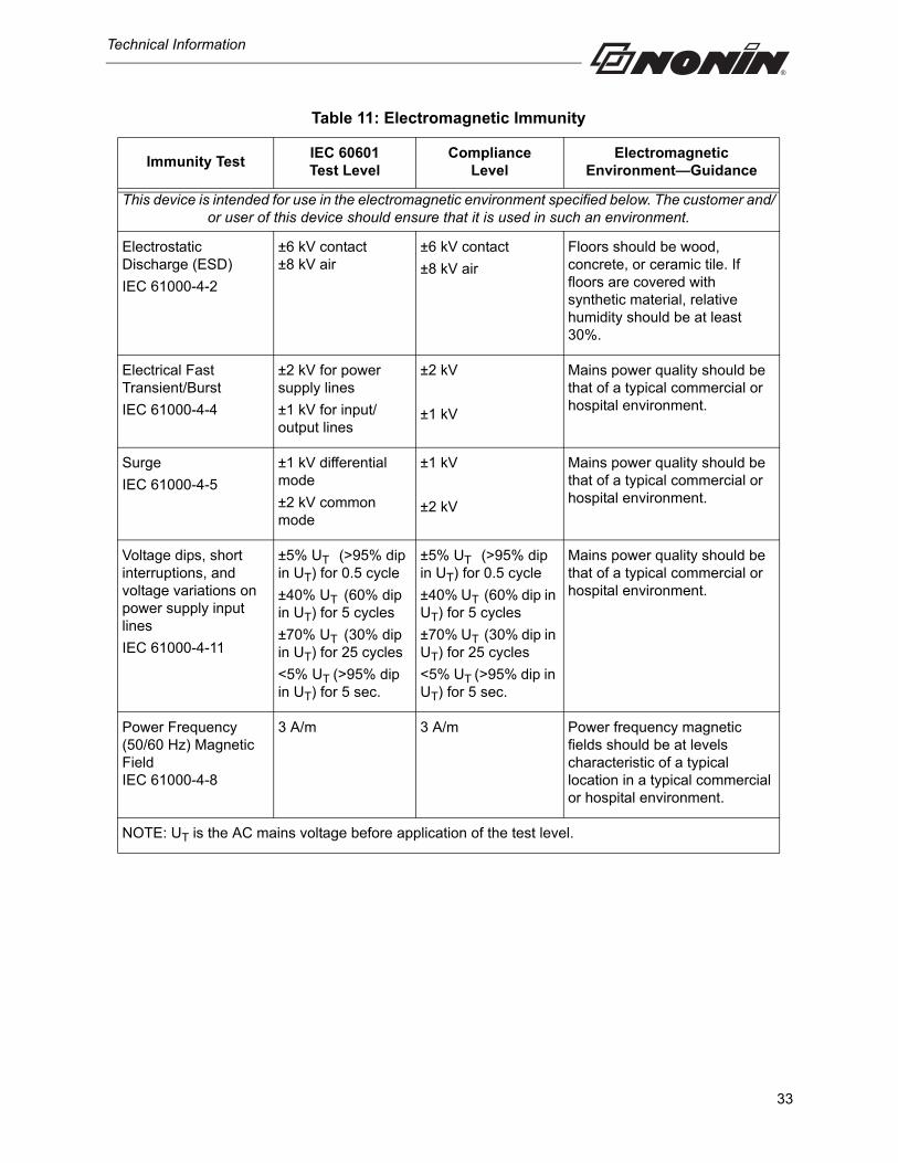
Table 11: Electromagnetic Immunity
Immunity TestIEC 60601Test Level
ComplianceLevel
Electromagnetic Environment—Guidance
This device is intended for use in the electromagnetic environment specified below. The customer and/or user of this device should ensure that it is used in such an environment.
Electrostatic Discharge (ESD)
IEC 61000-4-2
±6 kV contact±8 kV air
±6 kV contact
±8 kV air
Floors should be wood, concrete, or ceramic tile. If floors are covered with synthetic material, relative humidity should be at least 30%.
Electrical Fast Transient/Burst
IEC 61000-4-4
±2 kV for power supply lines
±1 kV for input/output lines
±2 kV
±1 kV
Mains power quality should be that of a typical commercial or hospital environment.
Surge
IEC 61000-4-5
±1 kV differential mode
±2 kV common mode
±1 kV
±2 kV
Mains power quality should be that of a typical commercial or hospital environment.
Voltage dips, short interruptions, and voltage variations on power supply input lines
IEC 61000-4-11
±5% UT (>95% dip in UT) for 0.5 cycle
±40% UT (60% dip in UT) for 5 cycles
±70% UT (30% dip in UT) for 25 cycles
<5% UT (>95% dip in UT) for 5 sec.
±5% UT (>95% dip in UT) for 0.5 cycle
±40% UT (60% dip in UT) for 5 cycles
±70% UT (30% dip in UT) for 25 cycles
<5% UT (>95% dip in UT) for 5 sec.
Mains power quality should be that of a typical commercial or hospital environment.
Power Frequency (50/60 Hz) Magnetic FieldIEC 61000-4-8
3 A/m 3 A/m Power frequency magnetic fields should be at levels characteristic of a typical location in a typical commercial or hospital environment.
NOTE: UT is the AC mains voltage before application of the test level.
33
Technical Information
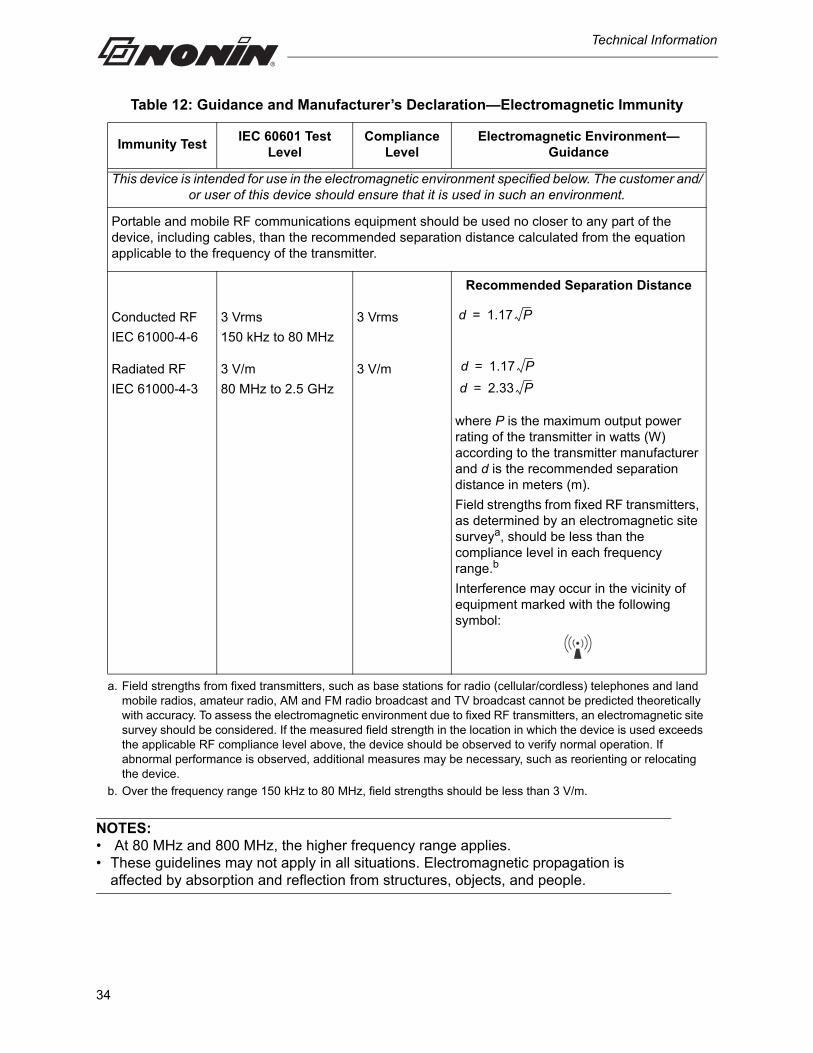
NOTES: • At 80 MHz and 800 MHz, the higher frequency range applies.• These guidelines may not apply in all situations. Electromagnetic propagation is
affected by absorption and reflection from structures, objects, and people.
Table 12: Guidance and Manufacturer’s Declaration—Electromagnetic Immunity
Immunity TestIEC 60601 Test
LevelCompliance
LevelElectromagnetic Environment—
Guidance
This device is intended for use in the electromagnetic environment specified below. The customer and/or user of this device should ensure that it is used in such an environment.
Portable and mobile RF communications equipment should be used no closer to any part of the device, including cables, than the recommended separation distance calculated from the equation applicable to the frequency of the transmitter.
Recommended Separation Distance
Conducted RF
IEC 61000-4-6
3 Vrms
150 kHz to 80 MHz
3 Vrms
Radiated RF
IEC 61000-4-3
3 V/m
80 MHz to 2.5 GHz
3 V/m
where P is the maximum output power rating of the transmitter in watts (W) according to the transmitter manufacturer and d is the recommended separation distance in meters (m).
Field strengths from fixed RF transmitters, as determined by an electromagnetic site surveya, should be less than the compliance level in each frequency range.b
Interference may occur in the vicinity of equipment marked with the following symbol:
a. Field strengths from fixed transmitters, such as base stations for radio (cellular/cordless) telephones and land mobile radios, amateur radio, AM and FM radio broadcast and TV broadcast cannot be predicted theoretically with accuracy. To assess the electromagnetic environment due to fixed RF transmitters, an electromagnetic site survey should be considered. If the measured field strength in the location in which the device is used exceeds the applicable RF compliance level above, the device should be observed to verify normal operation. If abnormal performance is observed, additional measures may be necessary, such as reorienting or relocating the device.
b. Over the frequency range 150 kHz to 80 MHz, field strengths should be less than 3 V/m.
d 1.17 P=
d 1.17 P=
d 2.33 P=
34
Technical Information
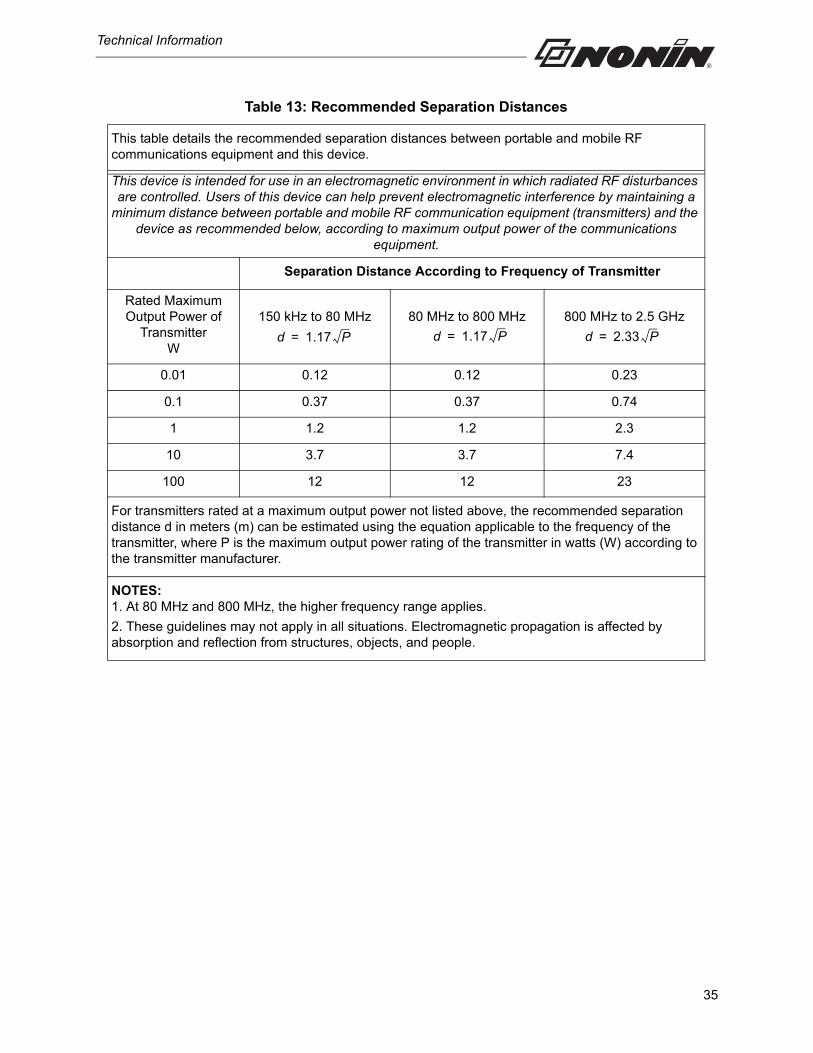
Table 13: Recommended Separation Distances
This table details the recommended separation distances between portable and mobile RF communications equipment and this device.
This device is intended for use in an electromagnetic environment in which radiated RF disturbances are controlled. Users of this device can help prevent electromagnetic interference by maintaining a
minimum distance between portable and mobile RF communication equipment (transmitters) and the device as recommended below, according to maximum output power of the communications
equipment.
Separation Distance According to Frequency of Transmitter
Rated Maximum Output Power of
Transmitter W
150 kHz to 80 MHz 80 MHz to 800 MHz 800 MHz to 2.5 GHz
0.01 0.12 0.12 0.23
0.1 0.37 0.37 0.74
1 1.2 1.2 2.3
10 3.7 3.7 7.4
100 12 12 23
For transmitters rated at a maximum output power not listed above, the recommended separation distance d in meters (m) can be estimated using the equation applicable to the frequency of the transmitter, where P is the maximum output power rating of the transmitter in watts (W) according to the transmitter manufacturer.
NOTES: 1. At 80 MHz and 800 MHz, the higher frequency range applies.
2. These guidelines may not apply in all situations. Electromagnetic propagation is affected by absorption and reflection from structures, objects, and people.
d 1.17 P= d 1.17 P= d 2.33 P=
35
Technical Information
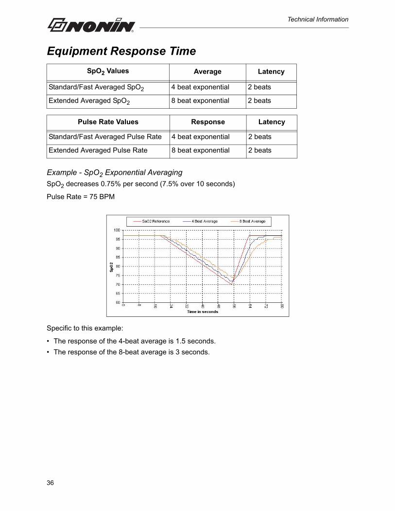
Equipment Response Time
Example - SpO2 Exponential Averaging
SpO2 decreases 0.75% per second (7.5% over 10 seconds)
Pulse Rate = 75 BPM
Specific to this example:
• The response of the 4-beat average is 1.5 seconds.
• The response of the 8-beat average is 3 seconds.
SpO2 Values Average Latency
Standard/Fast Averaged SpO2 4 beat exponential 2 beats
Extended Averaged SpO2 8 beat exponential 2 beats
Pulse Rate Values Response Latency
Standard/Fast Averaged Pulse Rate 4 beat exponential 2 beats
Extended Averaged Pulse Rate 8 beat exponential 2 beats
36
Technical Information
Testing SummarySpO2 accuracy, and low perfusion testing were conducted by Nonin Medical, Inc., as described below:
SpO2 Accuracy Testing
SpO2 accuracy testing is conducted during induced hypoxia studies on healthy, non-smoking, light- to dark-skinned subjects during motion and no-motion conditions in an independent research laboratory. The measured arterial hemoglobin saturation value (SpO2) of the sensors is compared to arterial hemoglobin oxygen (SaO2) value, determined from blood samples with a laboratory co-oximeter. The accuracy of the sensors in comparison to the co-oximeter samples measured over the SpO2 range of 70 - 100%. Accuracy data is calculated using the root-mean-squared (Arms value) for all subjects, per ISO 9919:2005, Medical Electrical Equipment—Particular requirements for the basic safety and essential performance of pulse oximeter equipment for medical use.
Pulse Rate Motion Testing
This test measures pulse rate oximeter accuracy with motion artifact simulation introduced by a pulse oximeter tester. This test determines whether the oximeter meets the criteria of ISO 9919:2005 for pulse rate during simulated movement, tremor, and spike motions.
Low Perfusion Testing
This test uses an SpO2 Simulator to provide a simulated pulse rate, with adjustable amplitude settings at various SpO2 levels for the oximeter to read. The oximeter must maintain accuracy in accordance with ISO 9919:2005 for heart rate and SpO2 at the lowest obtainable pulse amplitude (0.3% modulation).
37
Technical Information
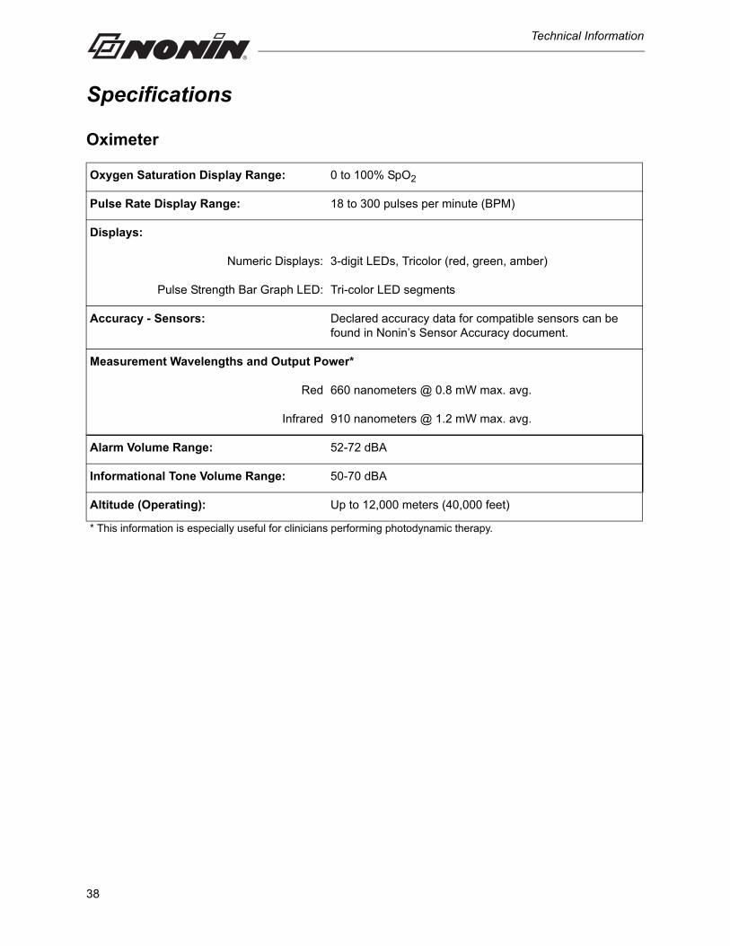
Specifications
Oximeter
Oxygen Saturation Display Range: 0 to 100% SpO2
Pulse Rate Display Range: 18 to 300 pulses per minute (BPM)
Displays:
Numeric Displays: 3-digit LEDs, Tricolor (red, green, amber)
Pulse Strength Bar Graph LED: Tri-color LED segments
Accuracy - Sensors: Declared accuracy data for compatible sensors can be found in Nonin’s Sensor Accuracy document.
Measurement Wavelengths and Output Power*
Red 660 nanometers @ 0.8 mW max. avg.
Infrared 910 nanometers @ 1.2 mW max. avg.
Alarm Volume Range: 52-72 dBA
Informational Tone Volume Range: 50-70 dBA
Altitude (Operating): Up to 12,000 meters (40,000 feet)
* This information is especially useful for clinicians performing photodynamic therapy.
38
Technical Information
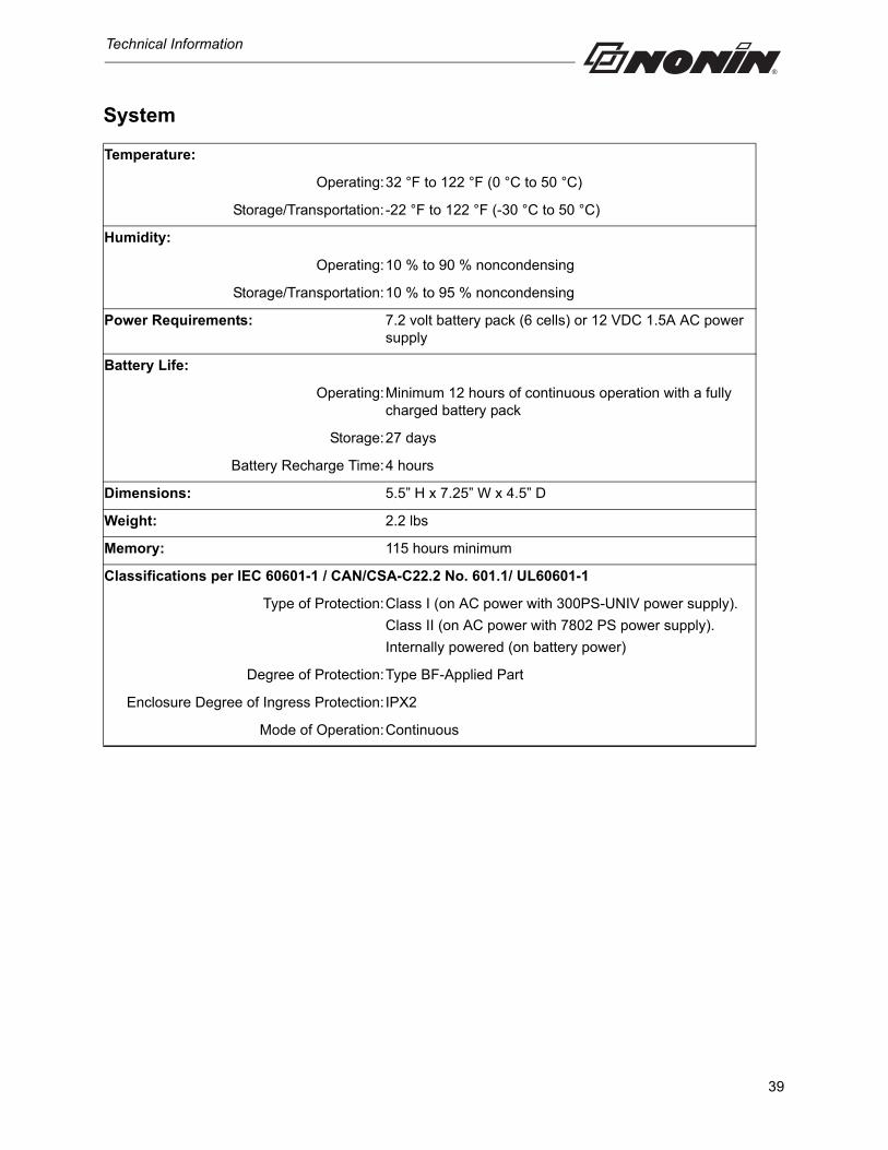
System
Temperature:
Operating:32 °F to 122 °F (0 °C to 50 °C)
Storage/Transportation:-22 °F to 122 °F (-30 °C to 50 °C)
Humidity:
Operating:10 % to 90 % noncondensing
Storage/Transportation:10 % to 95 % noncondensing
Power Requirements: 7.2 volt battery pack (6 cells) or 12 VDC 1.5A AC power supply
Battery Life:
Operating:Minimum 12 hours of continuous operation with a fully charged battery pack
Storage:27 days
Battery Recharge Time:4 hours
Dimensions: 5.5” H x 7.25” W x 4.5” D
Weight: 2.2 lbs
Memory: 115 hours minimum
Classifications per IEC 60601-1 / CAN/CSA-C22.2 No. 601.1/ UL60601-1
Type of Protection:Class I (on AC power with 300PS-UNIV power supply).
Class II (on AC power with 7802 PS power supply).
Internally powered (on battery power)
Degree of Protection:Type BF-Applied Part
Enclosure Degree of Ingress Protection: IPX2
Mode of Operation:Continuous
39
Technical Information
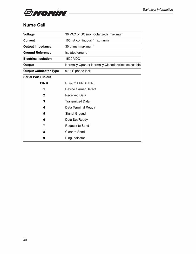
Nurse Call
Voltage 30 VAC or DC (non-polarized), maximum
Current 100mA continuous (maximum)
Output Impedance 30 ohms (maximum)
Ground Reference Isolated ground
Electrical Isolation 1500 VDC
Output Normally Open or Normally Closed; switch selectable
Output Connector Type 0.141” phone jack
Serial Port Pin-out
PIN # RS-232 FUNCTION
1 Device Carrier Detect
2 Received Data
3 Transmitted Data
4 Data Terminal Ready
5 Signal Ground
6 Data Set Ready
7 Request to Send
8 Clear to Send
9 Ring Indicator
40