Embed Size (px)
Citation preview
P/N 71-007269 Rev A
Avalanche™ Installation
This document provides instructions for installing and connecting Avalanche appliances, as well as instructions for installing and running the Avalanche software.
Notes: • If your hardware is a Spirent C1 appliance (SPT-C1), refer to the Spirent C1 Installation Instructions and Spirent C1 Quick Reference, for information on installing and connecting this appliance. You use the Spirent TestCenter Administration window in the Avalanche Commander GUI to configure the SPT-C1. Refer to the online Help for more information.
• If your hardware is a Spirent C100 Multi-Purpose appliance (SPT-C100-MP), use the Spirent TestCenter Administration window in the Avalanche Commander GUI to configure the SPT-C100-MP. Refer to the online Help for more information.
In this document...
• Certifications and Standards . . . . 5
• Requirements . . . . 6
• System Description . . . . 10
• Requesting Your Avalanche License Key . . . . 33
• Installing and Running Avalanche Software . . . . 33
• Installing the License Key File for C100, 3100, and 290 . . . . 34
• Configuring Avalanche . . . . 36
• Shutting Down or Rebooting Avalanche . . . . 38
• Related Documentation . . . . 38
• How to Contact Us . . . . 40
Avalanche™ Installation Instructions | 1, 3/14
Avalanche™ Installation
Copyright
© 2014 Spirent Communications, Inc. All Rights Reserved.
All of the company names and/or brand names and/or product names referred to in this document, in particular, the name “Spirent” and its logo device, are either registered trademarks or trademarks of Spirent plc and its subsidiaries, pending registration in accordance with relevant national laws. All other registered trademarks or trademarks are the property of their respective owners. The information contained in this document is subject to change without notice and does not represent a commitment on the part of Spirent Communications. The information in this document is believed to be accurate and reliable, however, Spirent Communications assumes no responsibility or liability for any errors or inaccuracies that may appear in the document.
Limited Warranty
Spirent Communications, Inc. (“Spirent”) warrants that its Products will conform to the description on the face of order, that it will convey good title thereto, and that the Product will be delivered free from any lawful security interest or other lien or encumbrance.
Spirent further warrants to Customer that hardware which it supplies and the tangible media on which it supplies software will be free from significant defects in materials and workmanship for a period of twelve (12) months, except as otherwise noted, from the date of delivery (the “Hardware Warranty Period”), under normal use and conditions.
To the extent the Product is or contains software (“Software”), Spirent also warrants that, if properly used by Customer in accordance with the Software License Agreement, the Software which it supplies will operate in material conformity with the specifications supplied by Spirent for such Software for a period of ninety (90) days from the date of delivery (the “Software Warranty Period”). The “Product Warranty Period” shall mean the Hardware Warranty Period or the Software Warranty Period, as applicable. Spirent does not warrant that the functions contained in the Software will meet a specific requirement or that the operation will be uninterrupted or error free. Spirent shall have no warranty obligations whatsoever with respect to any Software which has been modified in any manner by Customer or any third party.
Defective Products and Software under warranty shall be, at Spirent's discretion, repaired or replaced or a credit issued to Customer's account for an amount equal to the price paid for such Product provided that: (a) such Product is returned to Spirent after first obtaining a return authorization number and shipping instructions, freight prepaid, to Spirent's location in the United States; (b) Customer provides a written explanation of the defect or Software failure claimed by Customer; and (c) the claimed defect actually exists and was not caused by neglect, accident, misuse, improper installation, improper repair, fire, flood, lightning, power surges, earthquake, or alteration. Spirent will ship repaired Products to Customer, freight prepaid, based on reasonable best efforts after the receipt of defective Products. Except as otherwise stated, any claim on account of defective materials or for any other cause whatsoever will conclusively be deemed waived by Customer unless written notice thereof is given to Spirent within the Warranty Period. Spirent reserves the
2 | Avalanche™ Installation Instructions P/N 71-007269 Rev A, 3/14
Avalanche™ Installation
right to change the warranty and service policy set forth above at any time, after reasonable notice and without liability to Customer.
TO THE EXTENT PERMITTED BY APPLICABLE LAW, ALL IMPLIED WARRANTIES, INCLUDING BUT NOT LIMITED TO IMPLIED WARRANTIES OF MERCHANTABILITY, NONINFRINGEMENT AND FITNESS FOR A PARTICULAR PURPOSE, ARE HEREBY EXCLUDED, AND THE LIABILITY OF SPIRENT, IF ANY, FOR DAMAGE RELATING TO ANY ALLEGEDLY DEFECTIVE PRODUCT SHALL BE LIMITED TO THE ACTUAL PRICE PAID BY THE CUSTOMER FOR SUCH PRODUCT. THE PROVISIONS SET FORTH ABOVE STATE SPIRENT'S ENTIRE RESPONSIBILITY AND CUSTOMER'S SOLE AND EXCLUSIVE REMEDY WITH RESPECT TO ANY BREACH OF ANY WARRANTY.
Safety Precautions
Warning: Calls attention to operating procedures or practices that should be followed to avoid bodily injury or damage to equipment.
Caution: Reflects conditions that could cause product damage or data loss.
Note: Describes limitations on the use of the equipment or procedure.
No User-Serviceable Parts
Warning: No user-serviceable parts inside. Do not open.Waarschuwing: Er zijn geen door de gebruiker te vervangen onderdelen. Niet openen.Attention: Aucune pièce se trouvant à l'intérieur ne peut être réparée ou remplacée par l'utilisateur. Ne pas ouvrir.
Battery Warning
Warning: There is the danger of explosion if the battery is replaced incorrectly. Replace the battery only with the same or equivalent type recommended by the manufacturer. Dis-pose of used batteries according to the manufacturer’s instructions.Waarschuwing: Er is ontploffingsgevaar als de batterij verkeerd vervangen wordt. Ver-vang de batterij slechts met hetzelfde of een equivalent type dat door de fabrikant aanbev-olen is. Gebruikte batterijen dienen overeenkomstig fabrieksvoorschriften weggeworpen te worden.Attention: Danger d'explosion si la pile n'est pas remplacée correctement. Ne la rem-placer que par une pile de type semblable ou équivalent, recommandée par le fabricant. Jeter les piles usagées conformément aux instructions du fabricant.
Lasers Warning
Warning: Because invisible radiation may be emitted from the aperture of the port when no fiber cable is connected, avoid exposure to radiation and do not stare into open apertures.
!
Avalanche™ Installation Instructions | 3P/N 71-007269 Rev A, 3/14
Avalanche™ Installation
Waarschuwing: Aangezien onzichtbare straling vanuit de opening van de poort kan komen als er geen fiberkabel aangesloten is, dient blootstelling aan straling en het kijken in open openingen vermeden te worden.Attention: Avant d'accéder à cet équipement connecté aux lignes électriques, ôter tout bijou (anneaux, colliers et montres compris). Lorsqu'ils sont branchés à l'alimentation et reliés à la terre, les objets métalliques chauffent, ce qui peut provoquer des blessures graves ou souder l'objet métallique aux bornes.
Calibration
At the time of manufacture, all components manufactured by Spirent Communications are calibrated in accordance with applicable procedures. Spirent Communications equipment is calibrated using national standards, consensus standards, and ratio-type measurements based on self-calibration techniques. By design, the equipment has no user adjustments and does not require further calibration. Products are calibrated within the published environmental specifications for the products. At the time of shipment, this Spirent Communications product met its published operating specifications.
Unpacking
Before opening the carton, examine the carton for damage. If damage is not visible, unpack the carton and check contents for damage. Save all packing materials. If damage is noted, forward an immediate request to the delivering carrier to perform an inspection and prepare a damage report. Save the container and packing material until contents are verified.
Concurrently, report the nature and extent of damage to Spirent Communications Customer Support so that action can be initiated to repair or replace damaged items, or instructions issued for returning items.
The responsibility of the manufacturer ends with delivery to the first carrier. All claims for loss, damage, or nondelivery must be made against the delivering carrier within 10 calendar days of receipt of shipment.
Damaged or Missing Equipment
If any equipment is damaged or missing, call (800) 774-7368 or (818) 676-2616 (international) for technical support. Registered users may also access the Spirent Communications support website at http://support.spirent.com. You may also email questions to [email protected].
4 | Avalanche™ Installation Instructions P/N 71-007269 Rev A, 3/14

Avalanche™ InstallationCertifications and Standards
Certifications and Standards
FCC
Avalanche complies with the limits for a Class A digital device in accordance with Part 15 of the FCC Rules. These limits are designed to provide reasonable protection against harmful interference when this equipment is operated in a commercial environment. Operation is subject to the following two conditions:
• This device may not cause harmful interference.
• This device must accept any interference received, including interference that may cause undesired operation.
This device generates, uses, and can radiate radio frequency energy if not installed and used in accordance with the instructions in this manual. Operating this equipment in a residential area is likely to cause harmful interference, and the customer will be required to rectify the interference at his or her own expense. This product requires the use of external shielded cables to maintain compliance pursuant to Part 15 of the FCC Rules.
CE
The CE symbol on the product label indicates this network appliance is compliant with the EMC Directive and Low Voltage Directive of the European Union. This product meets the following technical standards:
• EN 55022 — “Limits and Methods of Measurement of Radio Interference Characteristics of Information Technology Equipment.”
• EN 55024 — “Limits and methods of measurement of immunity characteristics for information technology equipment.”
• EN 60950 — “Safety of Information Technology Equipment.”
TUV
This product carries the cTUVus mark.
Avalanche™ Installation Instructions | 5P/N 71-007269 Rev A, 3/14
Avalanche™ InstallationRequirements
Environmental Considerations
This label is on all Spirent-provided electrical and electronic products that are sold and shipped (see Figure 1).
Figure 1. Waste of Electrical and Electronic Equipment (WEEE) Label
This label indicates that the product contains material that presents an environmental concern. Spirent encourages users of Spirent-provided electrical and electronic equipment to not dispose of the labeled products in waste collection units where the waste is destined for landfills. Electrical and electronic equipment should be collected separately and recycled, reused, and processed for recovery and waste treatment in accordance with your local, regional, and federal laws. If you have any questions regarding this labeling, please contact your Spirent Communications representative.
RequirementsThis section describes the Avalanche system requirements, cable requirements, and network connectivity. Refer to “System Description” on page 10 for chassis component descriptions.
Avalanche System Requirements
Avalanche requires standard AC input of 100-240 volts, 50/60 Hz.
Cable Requirements
You will need several customer-supplied cables, depending on your appliance model and the NIC configuration. For detailed cabling information, refer to the sections under “Connector Panel” beginning on page 13.
PC Requirements
Refer to the Release Notes for information on the minimum PC requirements.
Supported Hardware and NIC Configurations
Refer to the Release Notes for information on the hardware and NIC configurations that are supported in each release.
6 | Avalanche™ Installation Instructions P/N 71-007269 Rev A, 3/14
Avalanche™ InstallationRequirements
Network Connectivity
Avalanche communicates through the following ports:
• Spirent C100-MP — Avalanche Commander and Avalanche NEXT™ appliance platform. See Table 1 for the test port configuration.
• Spirent C100, Avalanche 3100B, 3100, 290 — 10/100/1000 Base-T LAN on motherboard (LOM) administrative port
• Spirent C100 — up to 16 test ports (copper 10/100/1000 and/or fiber GigE) and up to eight optional 10GbE test ports
• 3100B — See Table 3 on page 9 for the different test port configurations
• 3100 — Eight test ports (copper 10/100/1000 and/or fiber GigE) and two optional 10GbE test ports
• 290 — Four test ports (copper 10/100/1000)
Each of these ports is explained in the next section and in “Connector Panel” on page 13.
10/100/1000 or 10/100 Base-T Administrative Port
The administrative port must connect to a 10/100/1000 Base-T network. Spirent Communications suggests that appliances be connected through a switch and isolated from your test environment.
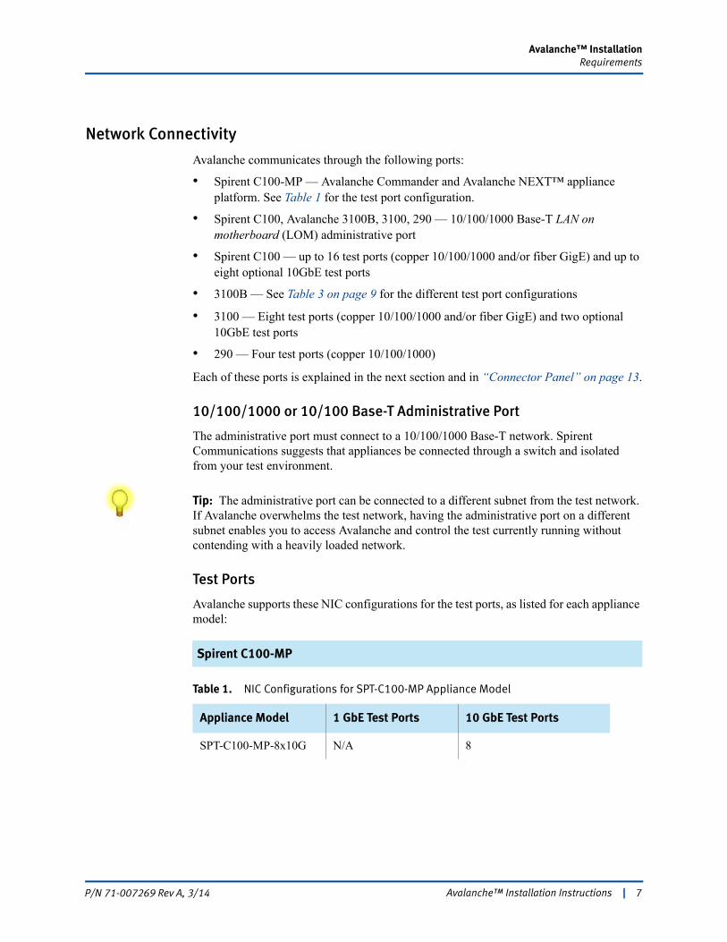
Tip: The administrative port can be connected to a different subnet from the test network. If Avalanche overwhelms the test network, having the administrative port on a different subnet enables you to access Avalanche and control the test currently running without contending with a heavily loaded network.
Test Ports
Avalanche supports these NIC configurations for the test ports, as listed for each appliance model:
Spirent C100-MP
Table 1. NIC Configurations for SPT-C100-MP Appliance Model
Appliance Model 1 GbE Test Ports 10 GbE Test Ports
SPT-C100-MP-8x10G N/A 8
Avalanche™ Installation Instructions | 7P/N 71-007269 Rev A, 3/14
Avalanche™ InstallationRequirements
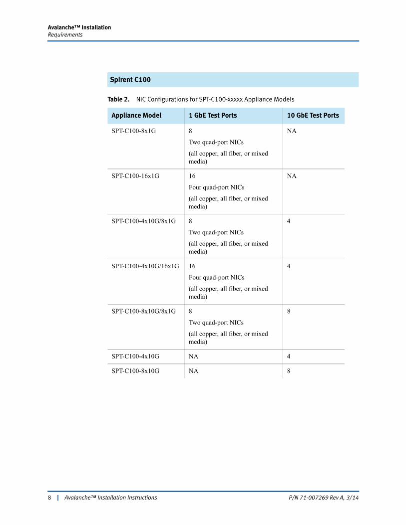
Spirent C100
Table 2. NIC Configurations for SPT-C100-xxxxx Appliance Models
Appliance Model 1 GbE Test Ports 10 GbE Test Ports
SPT-C100-8x1G 8
Two quad-port NICs
(all copper, all fiber, or mixed media)
NA
SPT-C100-16x1G 16
Four quad-port NICs
(all copper, all fiber, or mixed media)
NA
SPT-C100-4x10G/8x1G 8
Two quad-port NICs
(all copper, all fiber, or mixed media)
4
SPT-C100-4x10G/16x1G 16
Four quad-port NICs
(all copper, all fiber, or mixed media)
4
SPT-C100-8x10G/8x1G 8
Two quad-port NICs
(all copper, all fiber, or mixed media)
8
SPT-C100-4x10G NA 4
SPT-C100-8x10G NA 8
8 | Avalanche™ Installation Instructions P/N 71-007269 Rev A, 3/14
Avalanche™ InstallationRequirements
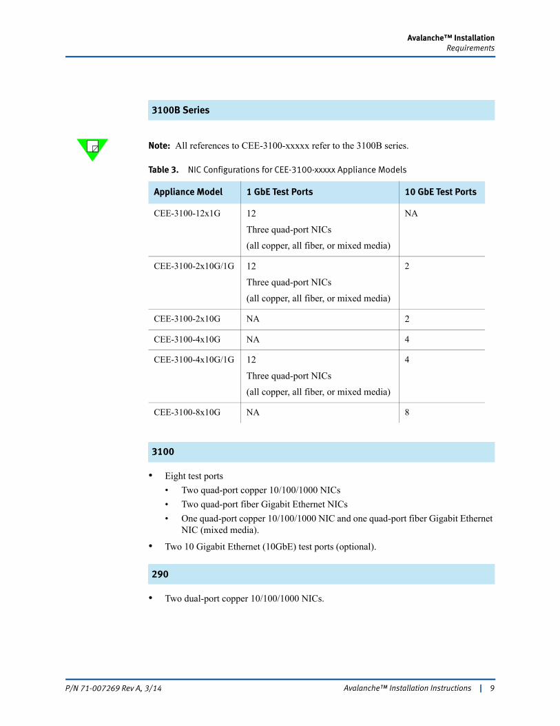
3100B Series
Note: All references to CEE-3100-xxxxx refer to the 3100B series.
3100
• Eight test ports
• Two quad-port copper 10/100/1000 NICs
• Two quad-port fiber Gigabit Ethernet NICs
• One quad-port copper 10/100/1000 NIC and one quad-port fiber Gigabit Ethernet NIC (mixed media).
• Two 10 Gigabit Ethernet (10GbE) test ports (optional).
290
• Two dual-port copper 10/100/1000 NICs.
Table 3. NIC Configurations for CEE-3100-xxxxx Appliance Models
Appliance Model 1 GbE Test Ports 10 GbE Test Ports
CEE-3100-12x1G 12
Three quad-port NICs
(all copper, all fiber, or mixed media)
NA
CEE-3100-2x10G/1G 12
Three quad-port NICs
(all copper, all fiber, or mixed media)
2
CEE-3100-2x10G NA 2
CEE-3100-4x10G NA 4
CEE-3100-4x10G/1G 12
Three quad-port NICs
(all copper, all fiber, or mixed media)
4
CEE-3100-8x10G NA 8
Avalanche™ Installation Instructions | 9P/N 71-007269 Rev A, 3/14
Avalanche™ InstallationSystem Description
System DescriptionThe Spirent C100/C100-MP, Spirent C1, Avalanche 3100B, 3100, and 290 are maintenance-free units that should not be disassembled. Servicing the units yourself jeopardizes your warranty. The primary external components of the appliance models are the network connector panel and power supply.
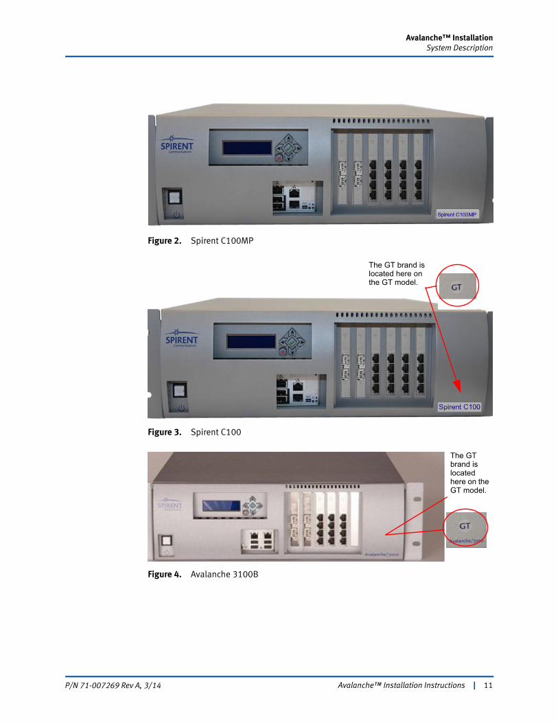
Notes: • The Spirent C100-MP includes the “MP” branding on the front panel (Figure 2 on page 11). This appliance can be used for the Avalanche Commander and/or Avalanche NEXT applications. Refer to the Avalanche NEXT documentation for information on this application.
• Refer to the Spirent C100 Installation Instructions for additional information about the SPT-C100 hardware (Figure 3 on page 11).
• Refer to the Spirent C1 Installation Instructions and the Spirent C1 Quick Reference for additional information and pictures of the SPT C1 hardware.
• The Spirent C100GT includes the “GT” branding on the front panel (Figure 3 on page 11). The GT model is identical to its standard counterpart, with this exception: • Standard model has 64GB of DRAM
• GT model has 128GB of DRAM
• The Avalanche 3100B (Figure 4 on page 11) includes an LCD branding panel that displays the management port IP address currently set for the appliance. You can also use this LCD to set the management network configuration. Refer to “Using the Appliance LCD” on page 29 for complete instructions.
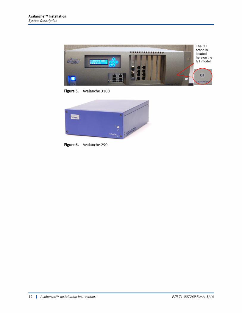
• The Avalanche 3100 (Figure 5 on page 12) includes an LCD branding panel that displays the management port IP address currently set for the appliance.
• Both the Avalanche 3100BGT and the Avalanche 3100GT include the “GT” branding on the front panel (Figure 4 and Figure 5 on page 12). The GT model is identical to its standard counterpart, with this exception: • Standard model has 48GB of DRAM
• GT model has 96GB of DRAM.
10 | Avalanche™ Installation Instructions P/N 71-007269 Rev A, 3/14
Avalanche™ InstallationSystem Description
Figure 2. Spirent C100MP
Figure 3. Spirent C100
Figure 4. Avalanche 3100B
The GT brand is located here on the GT model.
The GT brand is located here on the GT model.
Avalanche™ Installation Instructions | 11P/N 71-007269 Rev A, 3/14
Avalanche™ InstallationSystem Description
Figure 5. Avalanche 3100
Figure 6. Avalanche 290
The GT brand is located here on the GT model.
12 | Avalanche™ Installation Instructions P/N 71-007269 Rev A, 3/14
Avalanche™ InstallationSystem Description
Connector Panel
This section shows the connector panels and describes the necessary cabling for each Spirent C100 and C100-MP appliance model (Figure 7 through Figure 13 on page 19). Avalanche supports NIC configurations for the test ports, as listed for each model in “Test Ports” on page 7.
Note: The 10/100/1000 Gbps Copper admin port is in the same location for every configuration.
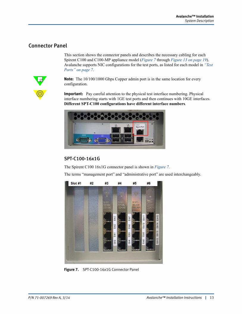
Important: Pay careful attention to the physical test interface numbering. Physical interface numbering starts with 1GE test ports and then continues with 10GE interfaces. Different SPT-C100 configurations have different interface numbers.
SPT-C100-16x1G
The Spirent C100 16x1G connector panel is shown in Figure 7.
The terms “management port” and “administrative port” are used interchangeably.
Figure 7. SPT-C100-16x1G Connector Panel
Avalanche™ Installation Instructions | 13P/N 71-007269 Rev A, 3/14
Avalanche™ InstallationSystem Description
The network data cables (customer supplied) connected to these ports must be as follows:
• Ethernet CAT-5 cable for the management port (Mgmt Port)
• Depending on the NIC configuration, the following for the test ports:
• 16 test ports (Eth0 - Eth15)
– Copper: RJ45 connector, Ethernet CAT-5 cable
– Fiber: LC Fiber Optic connector, Multi-Mode Fiber (62.5um or 50um) cable.
The mouse, keyboard, and printer connectors should not be used.
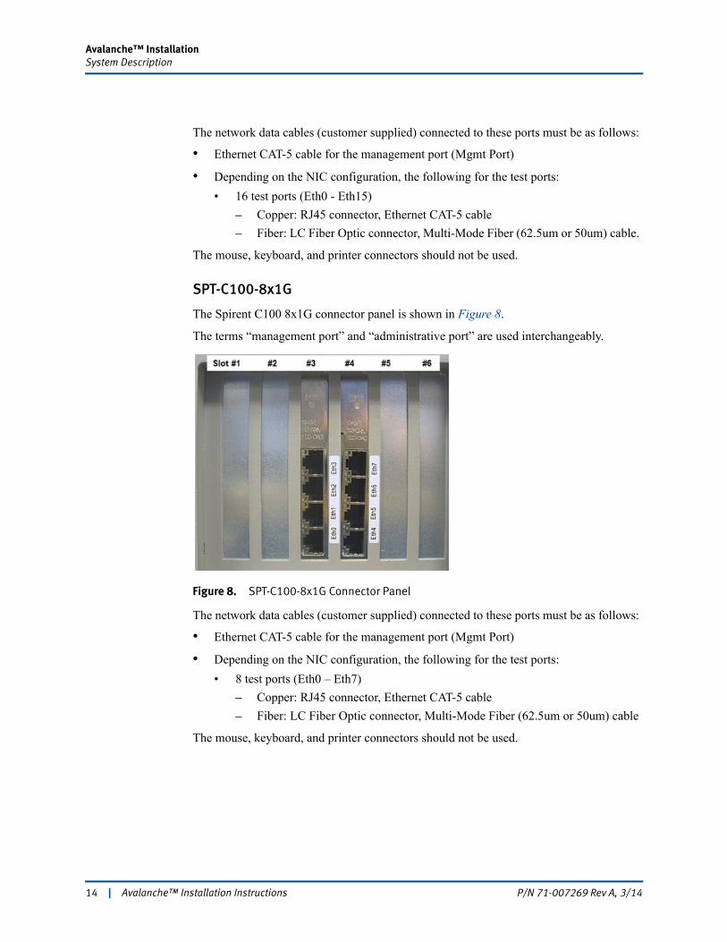
SPT-C100-8x1G
The Spirent C100 8x1G connector panel is shown in Figure 8.
The terms “management port” and “administrative port” are used interchangeably.
Figure 8. SPT-C100-8x1G Connector Panel
The network data cables (customer supplied) connected to these ports must be as follows:
• Ethernet CAT-5 cable for the management port (Mgmt Port)
• Depending on the NIC configuration, the following for the test ports:
• 8 test ports (Eth0 – Eth7)
– Copper: RJ45 connector, Ethernet CAT-5 cable
– Fiber: LC Fiber Optic connector, Multi-Mode Fiber (62.5um or 50um) cable
The mouse, keyboard, and printer connectors should not be used.
14 | Avalanche™ Installation Instructions P/N 71-007269 Rev A, 3/14
Avalanche™ InstallationSystem Description
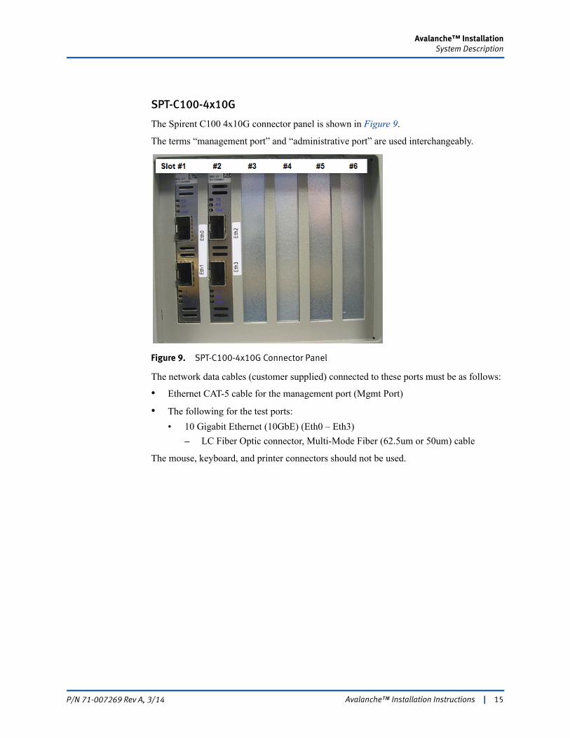
SPT-C100-4x10G
The Spirent C100 4x10G connector panel is shown in Figure 9.
The terms “management port” and “administrative port” are used interchangeably.
Figure 9. SPT-C100-4x10G Connector Panel
The network data cables (customer supplied) connected to these ports must be as follows:
• Ethernet CAT-5 cable for the management port (Mgmt Port)
• The following for the test ports:
• 10 Gigabit Ethernet (10GbE) (Eth0 – Eth3)
– LC Fiber Optic connector, Multi-Mode Fiber (62.5um or 50um) cable
The mouse, keyboard, and printer connectors should not be used.
Avalanche™ Installation Instructions | 15P/N 71-007269 Rev A, 3/14
Avalanche™ InstallationSystem Description
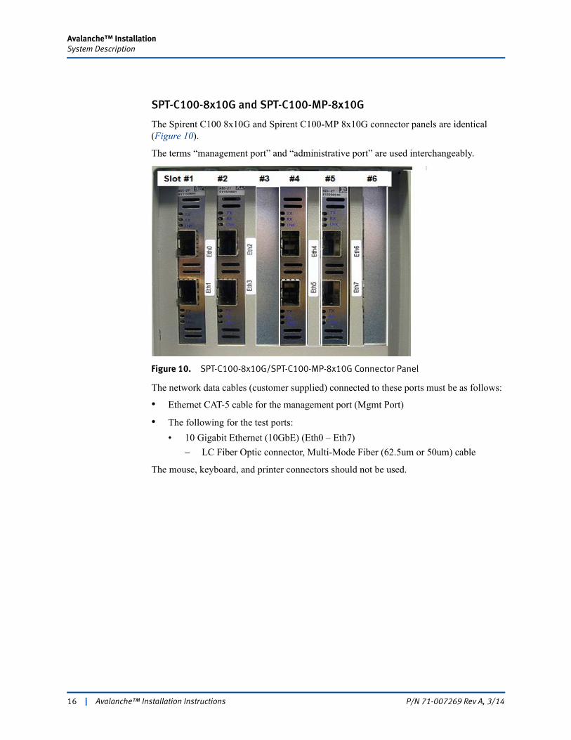
SPT-C100-8x10G and SPT-C100-MP-8x10G
The Spirent C100 8x10G and Spirent C100-MP 8x10G connector panels are identical (Figure 10).
The terms “management port” and “administrative port” are used interchangeably.
Figure 10. SPT-C100-8x10G/SPT-C100-MP-8x10G Connector Panel
The network data cables (customer supplied) connected to these ports must be as follows:
• Ethernet CAT-5 cable for the management port (Mgmt Port)
• The following for the test ports:
• 10 Gigabit Ethernet (10GbE) (Eth0 – Eth7)
– LC Fiber Optic connector, Multi-Mode Fiber (62.5um or 50um) cable
The mouse, keyboard, and printer connectors should not be used.
16 | Avalanche™ Installation Instructions P/N 71-007269 Rev A, 3/14
Avalanche™ InstallationSystem Description
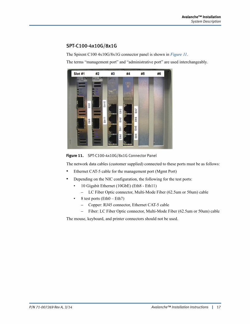
SPT-C100-4x10G/8x1G
The Spirent C100 4x10G/8x1G connector panel is shown in Figure 11.
The terms “management port” and “administrative port” are used interchangeably.
Figure 11. SPT-C100-4x10G/8x1G Connector Panel
The network data cables (customer supplied) connected to these ports must be as follows:
• Ethernet CAT-5 cable for the management port (Mgmt Port)
• Depending on the NIC configuration, the following for the test ports:
• 10 Gigabit Ethernet (10GbE) (Eth8 - Eth11)
– LC Fiber Optic connector, Multi-Mode Fiber (62.5um or 50um) cable
• 8 test ports (Eth0 – Eth7)
– Copper: RJ45 connector, Ethernet CAT-5 cable
– Fiber: LC Fiber Optic connector, Multi-Mode Fiber (62.5um or 50um) cable
The mouse, keyboard, and printer connectors should not be used.
Avalanche™ Installation Instructions | 17P/N 71-007269 Rev A, 3/14
Avalanche™ InstallationSystem Description
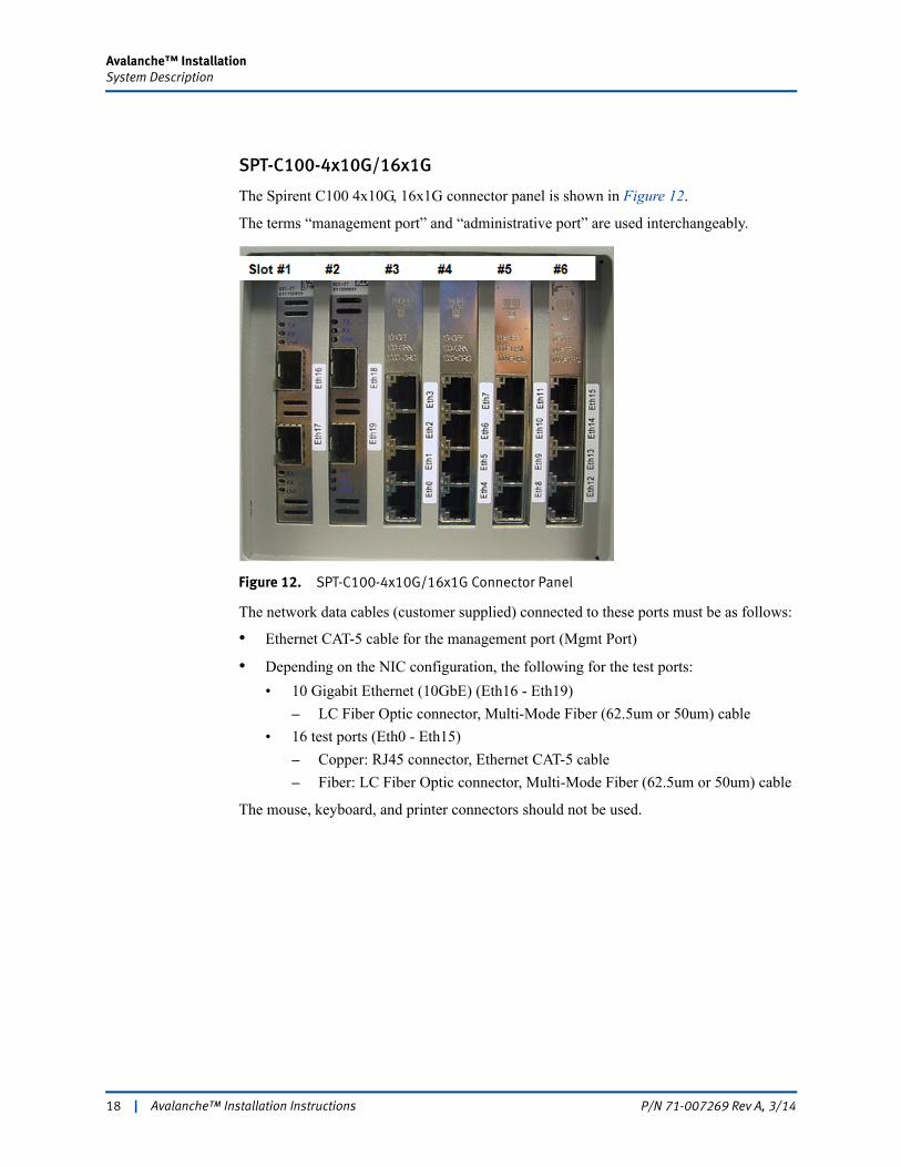
SPT-C100-4x10G/16x1G
The Spirent C100 4x10G, 16x1G connector panel is shown in Figure 12.
The terms “management port” and “administrative port” are used interchangeably.
Figure 12. SPT-C100-4x10G/16x1G Connector Panel
The network data cables (customer supplied) connected to these ports must be as follows:
• Ethernet CAT-5 cable for the management port (Mgmt Port)
• Depending on the NIC configuration, the following for the test ports:
• 10 Gigabit Ethernet (10GbE) (Eth16 - Eth19)
– LC Fiber Optic connector, Multi-Mode Fiber (62.5um or 50um) cable
• 16 test ports (Eth0 - Eth15)
– Copper: RJ45 connector, Ethernet CAT-5 cable
– Fiber: LC Fiber Optic connector, Multi-Mode Fiber (62.5um or 50um) cable
The mouse, keyboard, and printer connectors should not be used.
18 | Avalanche™ Installation Instructions P/N 71-007269 Rev A, 3/14
Avalanche™ InstallationSystem Description
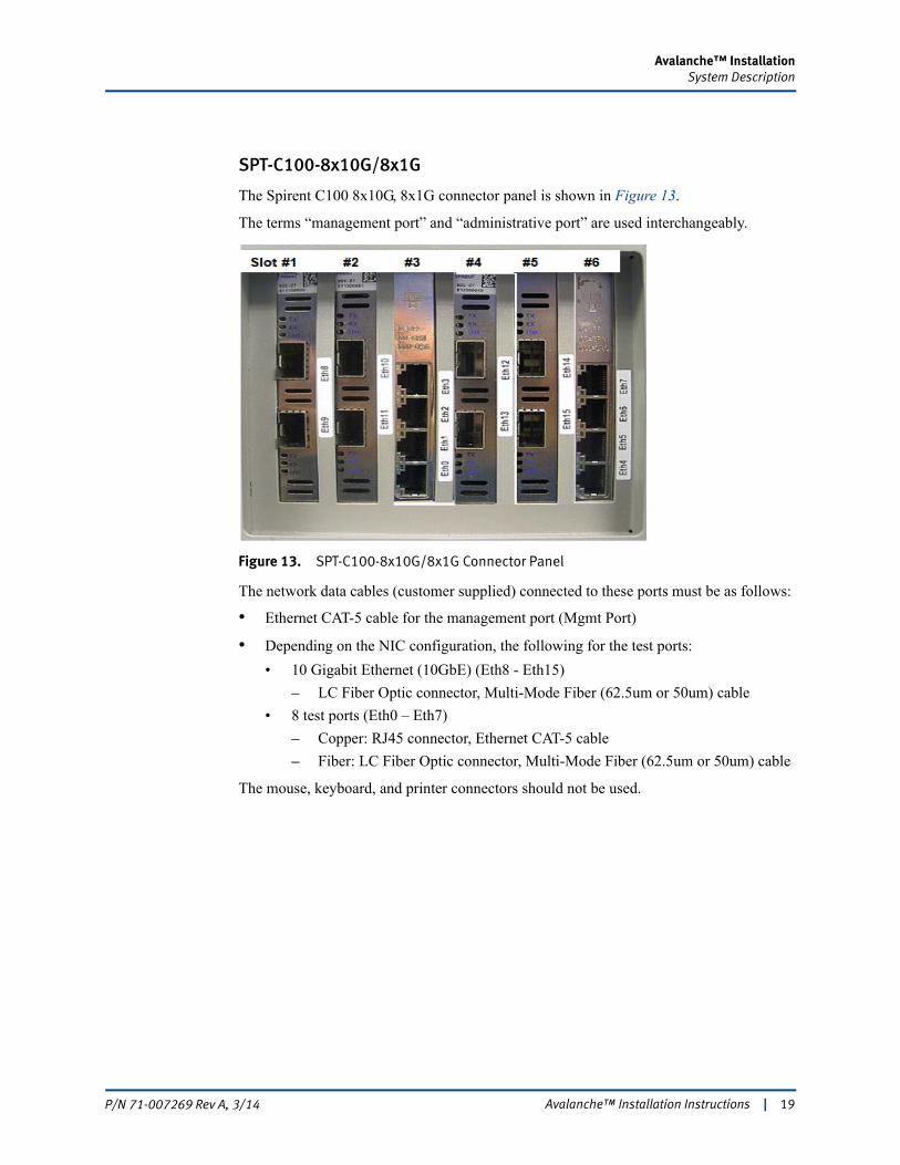
SPT-C100-8x10G/8x1G
The Spirent C100 8x10G, 8x1G connector panel is shown in Figure 13.
The terms “management port” and “administrative port” are used interchangeably.
Figure 13. SPT-C100-8x10G/8x1G Connector Panel
The network data cables (customer supplied) connected to these ports must be as follows:
• Ethernet CAT-5 cable for the management port (Mgmt Port)
• Depending on the NIC configuration, the following for the test ports:
• 10 Gigabit Ethernet (10GbE) (Eth8 - Eth15)
– LC Fiber Optic connector, Multi-Mode Fiber (62.5um or 50um) cable
• 8 test ports (Eth0 – Eth7)
– Copper: RJ45 connector, Ethernet CAT-5 cable
– Fiber: LC Fiber Optic connector, Multi-Mode Fiber (62.5um or 50um) cable
The mouse, keyboard, and printer connectors should not be used.
Avalanche™ Installation Instructions | 19P/N 71-007269 Rev A, 3/14

Avalanche™ InstallationSystem Description
This section shows the connector panels and describes the necessary cabling for each Avalanche appliance model (Figure 14 through Figure 25 on page 26). Avalanche supports NIC configurations for the test ports, as listed for each model in “Test Ports” on page 7.
Note: For details on reserving/releasing port groups, refer to the online Help under “Reserving/Releasing Appliance Port Groups.”
CEE-3100-12x1G
The Avalanche CEE-3100-12x1G connector panel is shown in Figure 14.
Figure 14. Avalanche CEE-3100-12x1G Connector Panel
The network data cables (customer supplied) connected to these ports must be as follows:
• Ethernet CAT-5 cable for the management port (Eth0)
• Depending on the NIC configuration, the following for the test ports:
• Twelve test ports (Eth0 - Eth11)
– Copper: RJ45 connector, Ethernet CAT-5 cable
– Fiber: LC Fiber Optic connector, Multi-Mode Fiber (62.5um or 50um) cable.
The mouse, keyboard, and printer connectors should not be used.
CEE-3100-2x10G/1G
The Avalanche CEE-3100-2x10G/1G connector panel is shown in Figure 15 on page 21.
(Eth0)
The terms “management port” and “administrative port” are used interchangeably.
20 | Avalanche™ Installation Instructions P/N 71-007269 Rev A, 3/14
Avalanche™ InstallationSystem Description
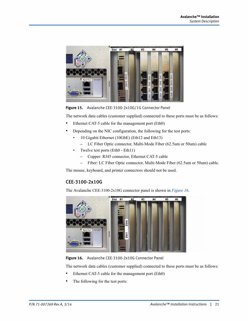
Figure 15. Avalanche CEE-3100-2x10G/1G Connector Panel
The network data cables (customer supplied) connected to these ports must be as follows:
• Ethernet CAT-5 cable for the management port (Eth0)
• Depending on the NIC configuration, the following for the test ports:
• 10 Gigabit Ethernet (10GbE) (Eth12 and Eth13)
– LC Fiber Optic connector, Multi-Mode Fiber (62.5um or 50um) cable
• Twelve test ports (Eth0 - Eth11)
– Copper: RJ45 connector, Ethernet CAT-5 cable
– Fiber: LC Fiber Optic connector, Multi-Mode Fiber (62.5um or 50um) cable.
The mouse, keyboard, and printer connectors should not be used.
CEE-3100-2x10G
The Avalanche CEE-3100-2x10G connector panel is shown in Figure 16.
Figure 16. Avalanche CEE-3100-2x10G Connector Panel
The network data cables (customer supplied) connected to these ports must be as follows:
• Ethernet CAT-5 cable for the management port (Eth0)
• The following for the test ports:
(Eth0)
(Eth0)
Avalanche™ Installation Instructions | 21P/N 71-007269 Rev A, 3/14
Avalanche™ InstallationSystem Description
• 10 Gigabit Ethernet (10GbE) (Eth0 and Eth1)
– LC Fiber Optic connector, Multi-Mode Fiber (62.5um or 50um) cable.
The mouse, keyboard, and printer connectors should not be used.
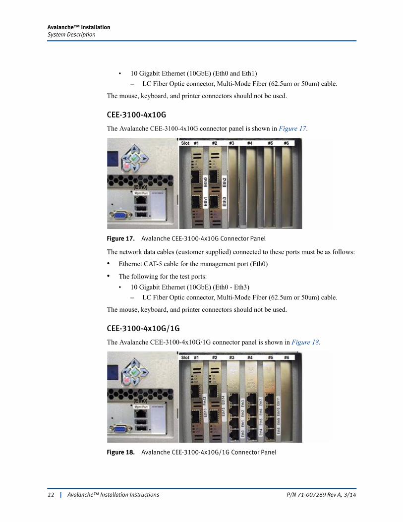
CEE-3100-4x10G
The Avalanche CEE-3100-4x10G connector panel is shown in Figure 17.
Figure 17. Avalanche CEE-3100-4x10G Connector Panel
The network data cables (customer supplied) connected to these ports must be as follows:
• Ethernet CAT-5 cable for the management port (Eth0)
• The following for the test ports:
• 10 Gigabit Ethernet (10GbE) (Eth0 - Eth3)
– LC Fiber Optic connector, Multi-Mode Fiber (62.5um or 50um) cable.
The mouse, keyboard, and printer connectors should not be used.
CEE-3100-4x10G/1G
The Avalanche CEE-3100-4x10G/1G connector panel is shown in Figure 18.
Figure 18. Avalanche CEE-3100-4x10G/1G Connector Panel
(Eth0)
(Eth0)
22 | Avalanche™ Installation Instructions P/N 71-007269 Rev A, 3/14

Avalanche™ InstallationSystem Description
The network data cables (customer supplied) connected to these ports must be as follows:
• Ethernet CAT-5 cable for the management port (Eth0)
• Depending on the NIC configuration, the following for the test ports:
• 10 Gigabit Ethernet (10GbE) (Eth12 - Eth15)
– LC Fiber Optic connector, Multi-Mode Fiber (62.5um or 50um) cable
• Twelve test ports (Eth0 - Eth11)
– Copper: RJ45 connector, Ethernet CAT-5 cable
– Fiber: LC Fiber Optic connector, Multi-Mode Fiber (62.5um or 50um) cable.
The mouse, keyboard, and printer connectors should not be used.
CEE-3100-8x10G
The Avalanche CEE-3100-8x10G connector panel is shown in Figure 19.
Figure 19. Avalanche CEE-3100-8x10G Connector Panel
The network data cables (customer supplied) connected to these ports must be as follows:
• Ethernet CAT-5 cable for the management port (Eth0)
• The following for the test ports:
• 10 Gigabit Ethernet (10GbE) (Eth0 - Eth7)
– LC Fiber Optic connector, Multi-Mode Fiber (62.5um or 50um) cable.
The mouse, keyboard, and printer connectors should not be used.
(Eth0)(EthO)
Avalanche™ Installation Instructions | 23P/N 71-007269 Rev A, 3/14
Avalanche™ InstallationSystem Description
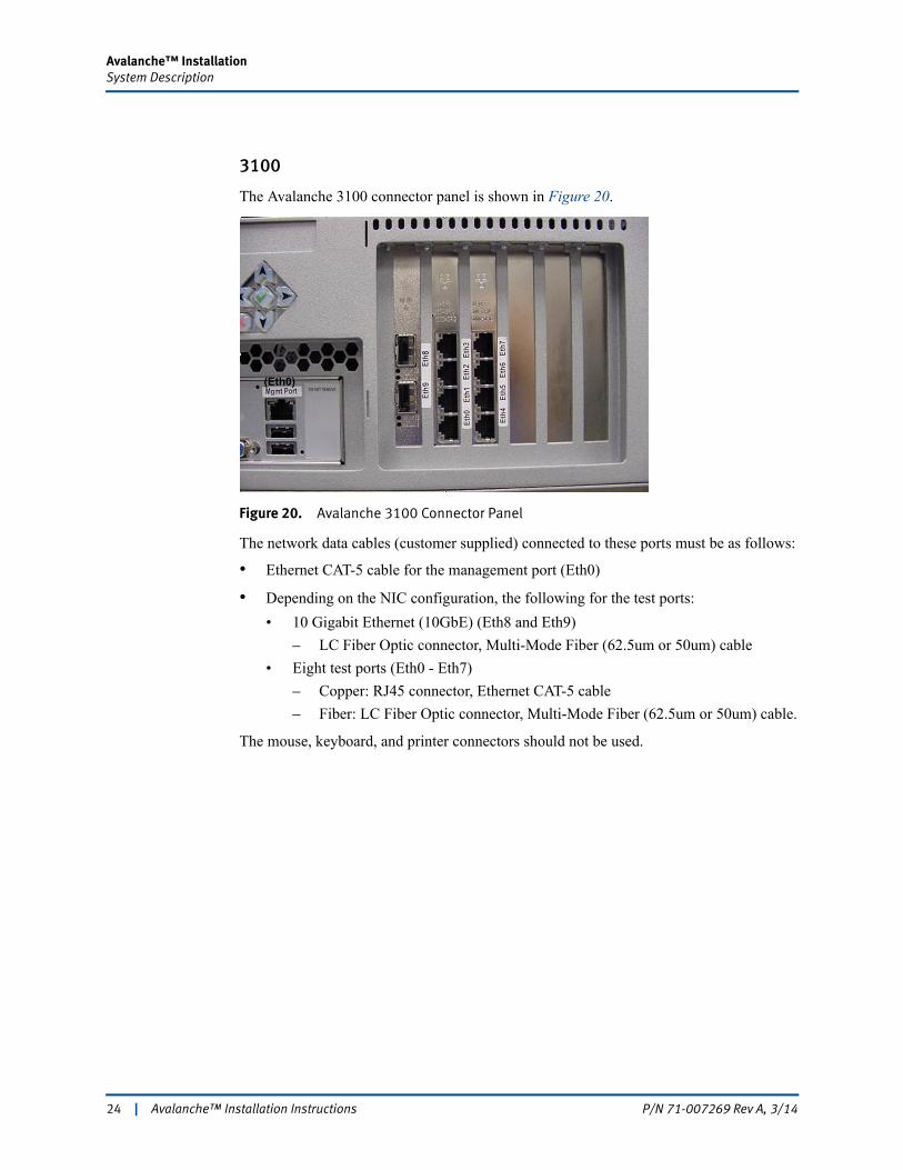
3100
The Avalanche 3100 connector panel is shown in Figure 20.
Figure 20. Avalanche 3100 Connector Panel
The network data cables (customer supplied) connected to these ports must be as follows:
• Ethernet CAT-5 cable for the management port (Eth0)
• Depending on the NIC configuration, the following for the test ports:
• 10 Gigabit Ethernet (10GbE) (Eth8 and Eth9)
– LC Fiber Optic connector, Multi-Mode Fiber (62.5um or 50um) cable
• Eight test ports (Eth0 - Eth7)
– Copper: RJ45 connector, Ethernet CAT-5 cable
– Fiber: LC Fiber Optic connector, Multi-Mode Fiber (62.5um or 50um) cable.
The mouse, keyboard, and printer connectors should not be used.
(Eth0)
24 | Avalanche™ Installation Instructions P/N 71-007269 Rev A, 3/14
Avalanche™ InstallationSystem Description
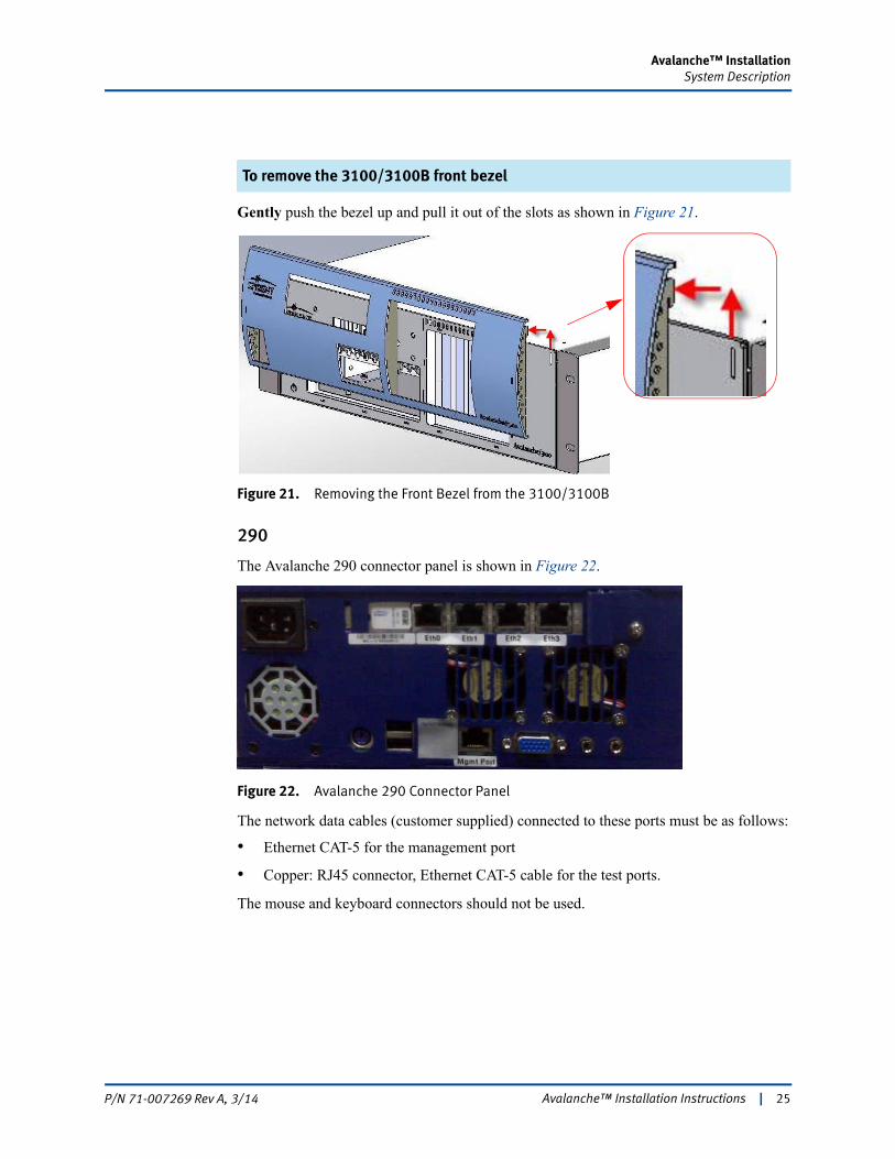
To remove the 3100/3100B front bezel
Gently push the bezel up and pull it out of the slots as shown in Figure 21.
Figure 21. Removing the Front Bezel from the 3100/3100B
290
The Avalanche 290 connector panel is shown in Figure 22.
Figure 22. Avalanche 290 Connector Panel
The network data cables (customer supplied) connected to these ports must be as follows:
• Ethernet CAT-5 for the management port
• Copper: RJ45 connector, Ethernet CAT-5 cable for the test ports.
The mouse and keyboard connectors should not be used.
Avalanche™ Installation Instructions | 25P/N 71-007269 Rev A, 3/14
Avalanche™ InstallationSystem Description
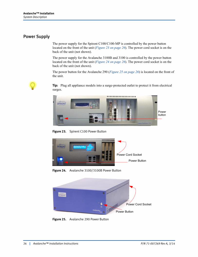
Power Supply
The power supply for the Spirent C100/C100-MP is controlled by the power button located on the front of the unit (Figure 23 on page 26). The power cord socket is on the back of the unit (not shown).
The power supply for the Avalanche 3100B and 3100 is controlled by the power button located on the front of the unit (Figure 24 on page 26). The power cord socket is on the back of the unit (not shown).
The power button for the Avalanche 290 (Figure 25 on page 26) is located on the front of the unit.
Tip: Plug all appliance models into a surge-protected outlet to protect it from electrical surges.
Figure 23. Spirent C100 Power Button
Figure 24. Avalanche 3100/3100B Power Button
Figure 25. Avalanche 290 Power Button
Power button
Power Button
Power Cord Socket
Power Button
Power Cord Socket
26 | Avalanche™ Installation Instructions P/N 71-007269 Rev A, 3/14
Avalanche™ InstallationSystem Description
Rack Mounting Considerations
The SPT-C100 requires 3U of rack-mount space (roughly 6” high x 10” deep x 13” wide) and is available with a rack-mount kit. If the unit must be rack-mounted, a shelf is recommended.
The Avalanche 3100B and 3100 require 3U of rack-mount space (roughly 6” high x 20” deep x 17” wide). The Avalanche 290 requires 2U of rack-mount space (roughly 4” high x 12.5” deep x 9” wide).
The 3100B and 3100 models ship with mounting brackets already attached. You can purchase a rack-mount kit as an option with the 290. The kit requires that you install two 290 units side by side. The rack-mount installation is easy, using the bolts supplied with the rack frame. The units can also be placed on a rack shelf.
Spirent appliance models may require safety agency evaluation, certification, and licensing. Check with your building inspector for requirements applicable to your location.
Notes on Rack Mounting
• Elevated operating ambient — If installed in a closed or multi-unit rack assembly, the operating ambient temperature of the rack environment may be greater than room ambient. Therefore, consideration should be given to installing the equipment in an environment compatible with the maximum ambient temperature of 30°C (86°F).
• Reduced air flow — Installation of the equipment in a rack should be such that the amount of airflow required for safe operation of the equipment is not compromised.
• Mechanical loading — Mounting of the equipment in the rack should be such that a hazardous condition is not achieved due to uneven mechanical loading. Do not stack other equipment on top of a system that is already rack-mounted.
• Circuit overloading — Consideration should be given to the connection of the equipment to the supply circuit and the effect that overloading of the circuits might have on over-current protection and supply wiring. Refer to equipment rating labels to ensure appropriate electrical loading of this system in a rack.
• Reliable earthing — Reliable earthing of rack-mounted equipment should be maintained. Particular attention should be given to supply connections other than direct connections to the branch circuit (for example, use of power strips).
Avalanche™ Installation Instructions | 27P/N 71-007269 Rev A, 3/14
Avalanche™ InstallationSystem Description
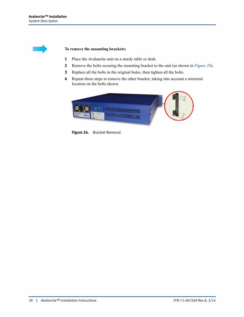
To remove the mounting brackets:
1 Place the Avalanche unit on a sturdy table or desk.
2 Remove the bolts securing the mounting bracket to the unit (as shown in Figure 26).
3 Replace all the bolts in the original holes, then tighten all the bolts.
4 Repeat these steps to remove the other bracket, taking into account a mirrored location on the bolts shown.
Figure 26. Bracket Removal
28 | Avalanche™ Installation Instructions P/N 71-007269 Rev A, 3/14
Avalanche™ InstallationSystem Description
Using the Appliance LCD
The Spirent C100-MP (Figure 2 on page 11), Spirent C100 Figure 3 on page 11), Avalanche 3100B (Figure 4 on page 11) and the Avalanche 3100 (Figure 5 on page 12) include an LCD that displays the management port IP address currently set for the appliance.
With the Spirent C100/C100-MP, and Avalanche 3100B, you can also use this LCD to set the management network configuration. This allows you to configure the system without connecting a monitor or keyboard.
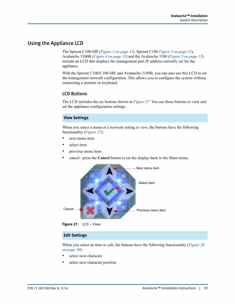
LCD Buttons
The LCD includes the six buttons shown in Figure 27. You use these buttons to view and set the appliance configuration settings.
View Settings
When you select a menu or a network setting to view, the buttons have the following functionality (Figure 27):
• next menu item
• select item
• previous menu item
• cancel– press the Cancel button to set the display back to the Main menu.
Figure 27. LCD – View
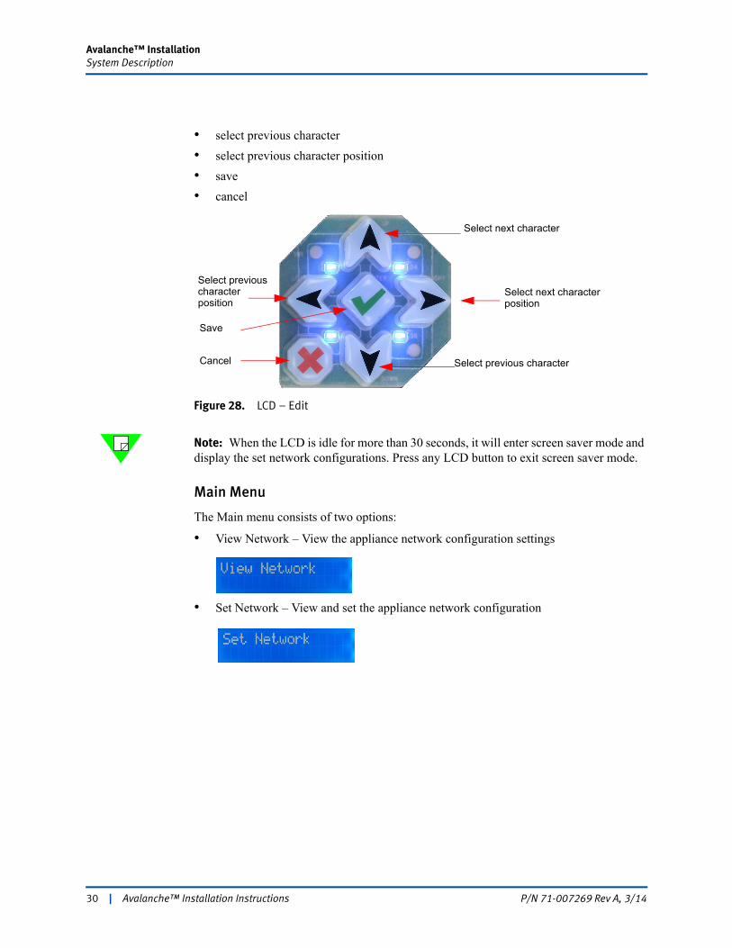
Edit Settings
When you select an item to edit, the buttons have the following functionality (Figure 28 on page 30):
• select next character
• select next character position
Next menu item
Cancel
Select item
Previous menu item
Avalanche™ Installation Instructions | 29P/N 71-007269 Rev A, 3/14
Avalanche™ InstallationSystem Description
• select previous character
• select previous character position
• save
• cancel
Figure 28. LCD – Edit
Note: When the LCD is idle for more than 30 seconds, it will enter screen saver mode and display the set network configurations. Press any LCD button to exit screen saver mode.
Main Menu
The Main menu consists of two options:
• View Network – View the appliance network configuration settings
• Set Network – View and set the appliance network configuration
Select next character
Select next character position
Select previous character position
Select previous characterCancel
Save
30 | Avalanche™ Installation Instructions P/N 71-007269 Rev A, 3/14
Avalanche™ InstallationSystem Description
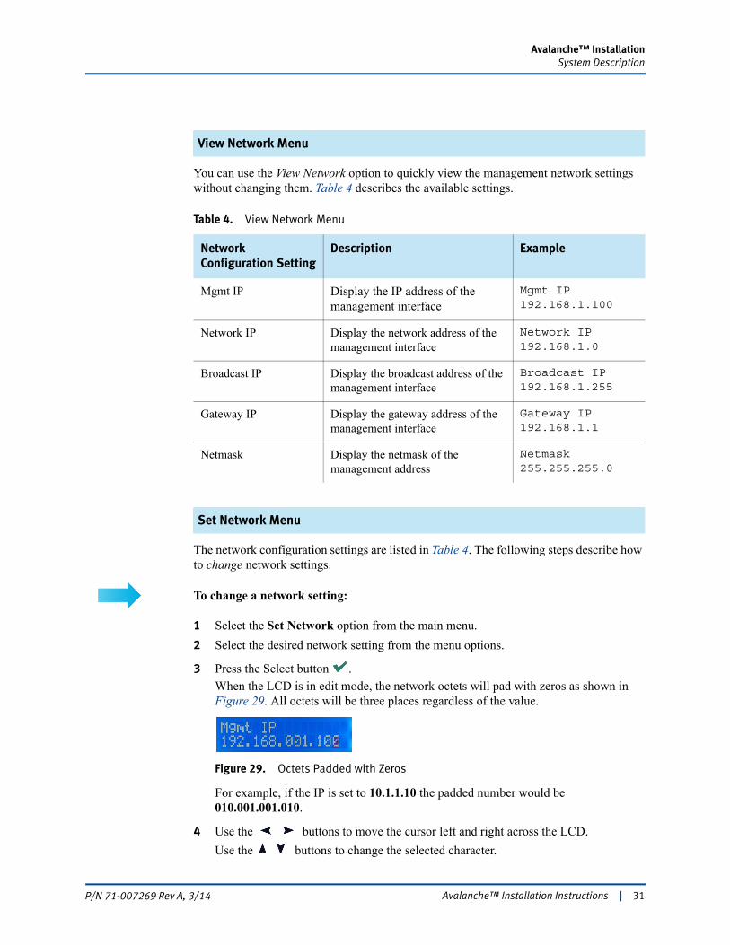
View Network Menu
You can use the View Network option to quickly view the management network settings without changing them. Table 4 describes the available settings.
Set Network Menu
The network configuration settings are listed in Table 4. The following steps describe how to change network settings.
To change a network setting:
1 Select the Set Network option from the main menu.
2 Select the desired network setting from the menu options.
3 Press the Select button . When the LCD is in edit mode, the network octets will pad with zeros as shown in Figure 29. All octets will be three places regardless of the value.
Figure 29. Octets Padded with Zeros
For example, if the IP is set to 10.1.1.10 the padded number would be 010.001.001.010.
4 Use the buttons to move the cursor left and right across the LCD. Use the buttons to change the selected character.
Table 4. View Network Menu
Network Configuration Setting
Description Example
Mgmt IP Display the IP address of the management interface
Mgmt IP 192.168.1.100
Network IP Display the network address of the management interface
Network IP 192.168.1.0
Broadcast IP Display the broadcast address of the management interface
Broadcast IP 192.168.1.255
Gateway IP Display the gateway address of the management interface
Gateway IP 192.168.1.1
Netmask Display the netmask of the management address
Netmask 255.255.255.0
Avalanche™ Installation Instructions | 31P/N 71-007269 Rev A, 3/14

Avalanche™ InstallationSystem Description
5 When you have finished your edits, press the button to save the changes. To cancel and discard the changes, press the button or select [No] when you are prompted to save.
Error Messages
These are the error messages that may display when you are updating the network settings. If an error occurs, your settings will not be saved until you correct the error condition.
Connecting Avalanche
Note: If you did not configure the management network settings using the LCD, in “Using the Appliance LCD” on page 29, use the instructions in this section to configure the those settings.
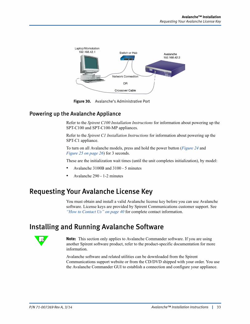
Avalanche connects and operates through your local network much like a standard PC. It boots with the IP address and subnet mask: 192.168.42.2/255.255.255.0.
To connect Avalanche:
1 Configure a laptop or workstation with the IP address and subnet mask: 192.168.42.1/255.255.255.0.
2 Connect the laptop or workstation to Avalanche’s administrative port with a crossover cable or through a (preferably full-duplex) network switch or hub (Figure 30 on page 33).
Error Message Cause Corrective Action
Incorrect Format Unable to Update
This error occurs when an incorrect address is entered. Each network octets must be between 0 and 255.
Press any LCD button to clear the message and enter a valid address.
Test Running Unable to Update
This error occurs when a test is actively running on the appliance. The ability to update the network settings from the LCD is disabled during a test.
Press any LCD button to clear the message and wait for the test to complete before attempting to edit the settings.
32 | Avalanche™ Installation Instructions P/N 71-007269 Rev A, 3/14
Avalanche™ InstallationRequesting Your Avalanche License Key
Figure 30. Avalanche’s Administrative Port
Powering up the Avalanche Appliance
Refer to the Spirent C100 Installation Instructions for information about powering up the SPT-C100 and SPT-C100-MP appliances.
Refer to the Spirent C1 Installation Instructions for information about powering up the SPT-C1 appliance.
To turn on all Avalanche models, press and hold the power button (Figure 24 and Figure 25 on page 26) for 3 seconds.
These are the initialization wait times (until the unit completes initialization), by model:
• Avalanche 3100B and 3100 - 5 minutes
• Avalanche 290 - 1-2 minutes
Requesting Your Avalanche License KeyYou must obtain and install a valid Avalanche license key before you can use Avalanche software. License keys are provided by Spirent Communications customer support. See “How to Contact Us” on page 40 for complete contact information.
Installing and Running Avalanche Software
Note: This section only applies to Avalanche Commander software. If you are using another Spirent software product, refer to the product-specific documentation for more information.
Avalanche software and related utilities can be downloaded from the Spirent Communications support website or from the CD/DVD shipped with your order. You use the Avalanche Commander GUI to establish a connection and configure your appliance.
Avalanche™ Installation Instructions | 33P/N 71-007269 Rev A, 3/14
Avalanche™ InstallationInstalling the License Key File for C100, 3100, and 290
To Install the Avalanche Commander
Run the Avalanche installation program on your PC, and follow the instructions in the InstallShield Wizard.
Note: When you uninstall the Avalanche software (via Add/Remove Programs on your PC), additional files may be left in the installation directory. The uninstaller only removes those files explicitly installed by the installer, and does not remove any additional files or directories created after installation.
To Run the Avalanche Commander
Run the Avalanche Commander (Layer 4 - 7 Application) by either:
• selecting Start > Programs > Spirent Communications > Spirent TestCenter version > Spirent TestCenter Layer 4-7 Application
• double-clicking the corresponding icon on your desktop.
Installing the License Key File for C100, 3100, and 290
Notes: • This section only applies to Avalanche Commander software. If you are using another Spirent software product, refer to the product-specific documentation for more information.
• If you are using the C100-MP, please refer to the C1 Installation Instructions for licensing information. The process for installing Avalanche Commander licensing is the same on C100-MP and C1 models.
After you have installed the Avalanche software on your PC, you must install the license key file that enables you to use the Avalanche software with your appliances.
To install the license key file:
1 In Avalanche Commander, select Administration > Licenses… from the menu to display the License Manager window (Figure 31 on page 35).
34 | Avalanche™ Installation Instructions P/N 71-007269 Rev A, 3/14
Avalanche™ InstallationInstalling the License Key File for C100, 3100, and 290
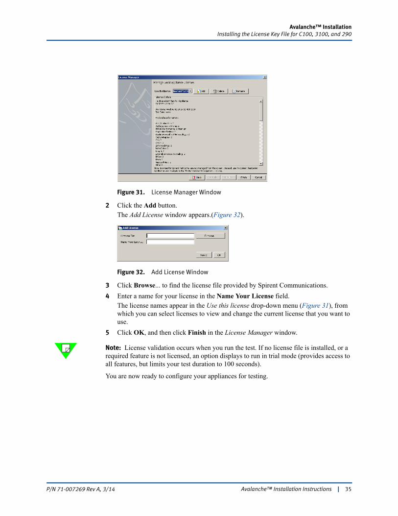
Figure 31. License Manager Window
2 Click the Add button. The Add License window appears.(Figure 32).
Figure 32. Add License Window
3 Click Browse... to find the license file provided by Spirent Communications.
4 Enter a name for your license in the Name Your License field. The license names appear in the Use this license drop-down menu (Figure 31), from which you can select licenses to view and change the current license that you want to use.
5 Click OK, and then click Finish in the License Manager window.
Note: License validation occurs when you run the test. If no license file is installed, or a required feature is not licensed, an option displays to run in trial mode (provides access to all features, but limits your test duration to 100 seconds).
You are now ready to configure your appliances for testing.
Avalanche™ Installation Instructions | 35P/N 71-007269 Rev A, 3/14
Avalanche™ InstallationConfiguring Avalanche
Configuring Avalanche
Notes: • This section only applies to Avalanche Commander software. If you are using another Spirent software product, refer to the product-specific documentation for more information.
• If you are using a C100-MP, refer to the C1 Installation Instructions, and the Avalanche Commander online Help under “Spirent TestCenter Administration Window.” The appliance configuration is the same on these platforms.
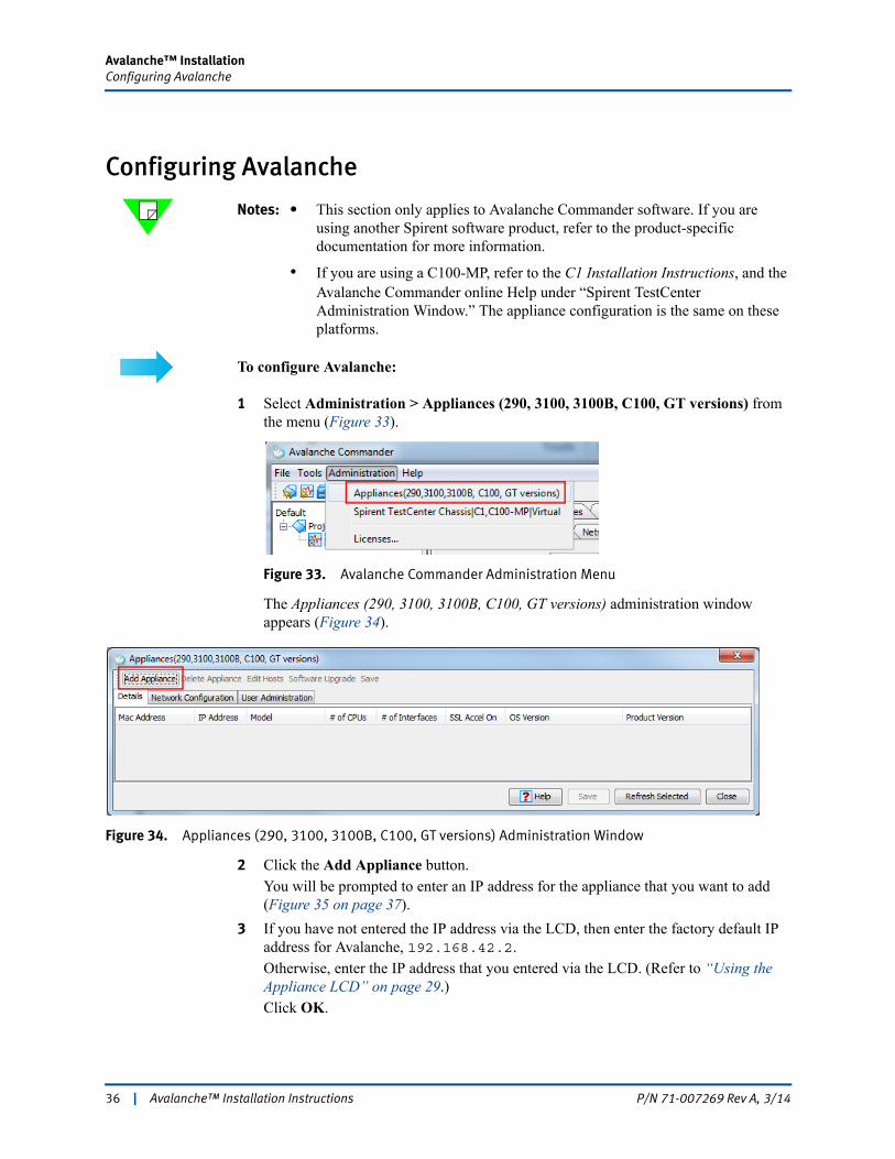
To configure Avalanche:
1 Select Administration > Appliances (290, 3100, 3100B, C100, GT versions) from the menu (Figure 33).
Figure 33. Avalanche Commander Administration Menu
The Appliances (290, 3100, 3100B, C100, GT versions) administration window appears (Figure 34).
Figure 34. Appliances (290, 3100, 3100B, C100, GT versions) Administration Window
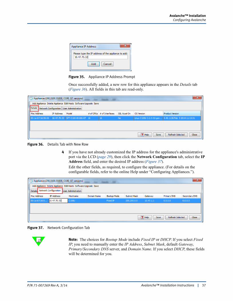
2 Click the Add Appliance button. You will be prompted to enter an IP address for the appliance that you want to add (Figure 35 on page 37).
3 If you have not entered the IP address via the LCD, then enter the factory default IP address for Avalanche, 192.168.42.2. Otherwise, enter the IP address that you entered via the LCD. (Refer to “Using the Appliance LCD” on page 29.)Click OK.
36 | Avalanche™ Installation Instructions P/N 71-007269 Rev A, 3/14
Avalanche™ InstallationConfiguring Avalanche
Figure 35. Appliance IP Address Prompt
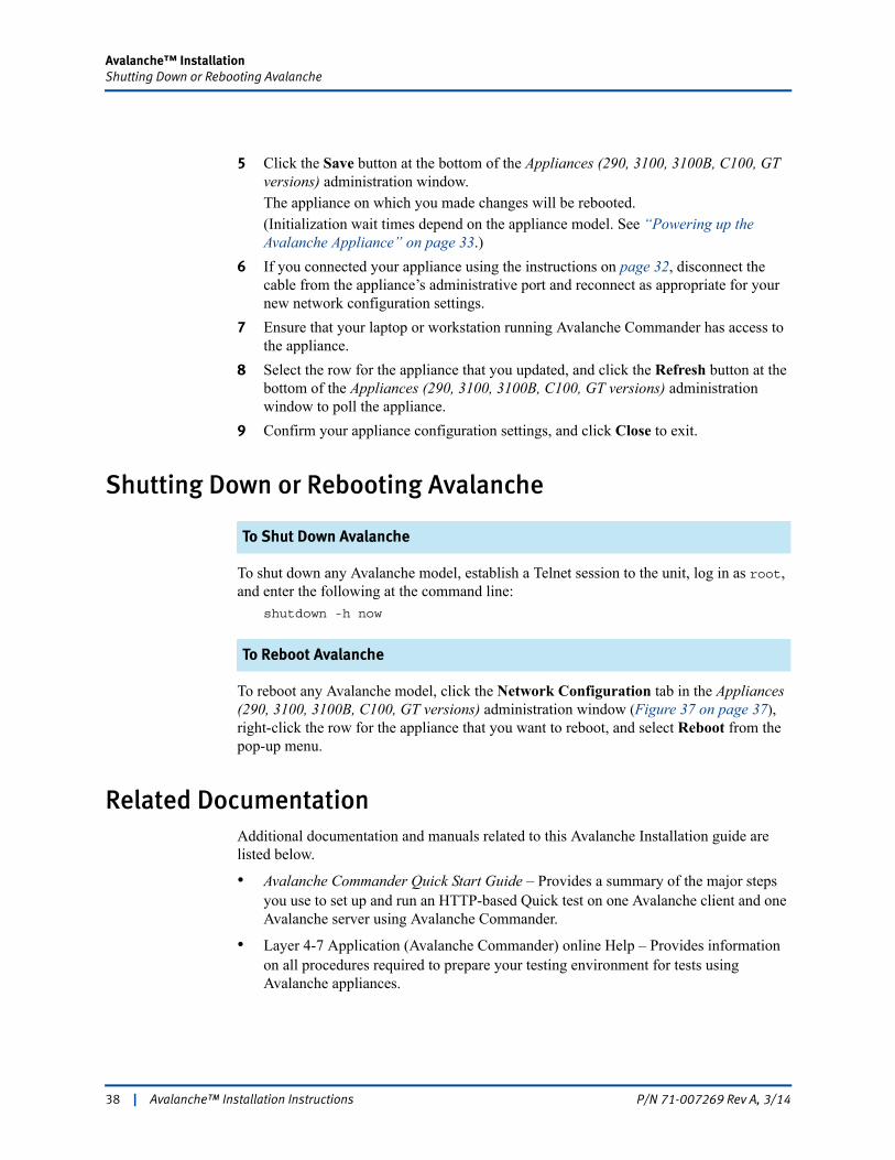
Once successfully added, a new row for this appliance appears in the Details tab (Figure 36). All fields in this tab are read-only.
Figure 36. Details Tab with New Row
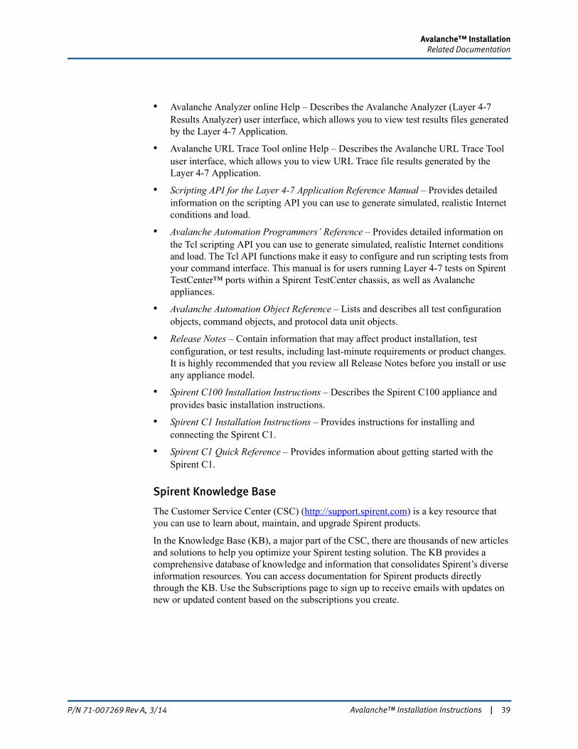
4 If you have not already customized the IP address for the appliance's administrative port via the LCD (page 29), then click the Network Configuration tab, select the IP Address field, and enter the desired IP address (Figure 37). Edit the other fields, as required, to configure the appliance. (For details on the configurable fields, refer to the online Help under “Configuring Appliances.”).
Figure 37. Network Configuration Tab
Note: The choices for Bootup Mode include Fixed IP or DHCP. If you select Fixed IP, you need to manually enter the IP Address, Subnet Mask, default Gateway, Primary/Secondary DNS server, and Domain Name. If you select DHCP, these fields will be determined for you.
Avalanche™ Installation Instructions | 37P/N 71-007269 Rev A, 3/14
Avalanche™ InstallationShutting Down or Rebooting Avalanche
5 Click the Save button at the bottom of the Appliances (290, 3100, 3100B, C100, GT versions) administration window. The appliance on which you made changes will be rebooted. (Initialization wait times depend on the appliance model. See “Powering up the Avalanche Appliance” on page 33.)
6 If you connected your appliance using the instructions on page 32, disconnect the cable from the appliance’s administrative port and reconnect as appropriate for your new network configuration settings.
7 Ensure that your laptop or workstation running Avalanche Commander has access to the appliance.
8 Select the row for the appliance that you updated, and click the Refresh button at the bottom of the Appliances (290, 3100, 3100B, C100, GT versions) administration window to poll the appliance.
9 Confirm your appliance configuration settings, and click Close to exit.
Shutting Down or Rebooting Avalanche
To Shut Down Avalanche
To shut down any Avalanche model, establish a Telnet session to the unit, log in as root, and enter the following at the command line:
shutdown -h now
To Reboot Avalanche
To reboot any Avalanche model, click the Network Configuration tab in the Appliances (290, 3100, 3100B, C100, GT versions) administration window (Figure 37 on page 37), right-click the row for the appliance that you want to reboot, and select Reboot from the pop-up menu.
Related DocumentationAdditional documentation and manuals related to this Avalanche Installation guide are listed below.
• Avalanche Commander Quick Start Guide – Provides a summary of the major steps you use to set up and run an HTTP-based Quick test on one Avalanche client and one Avalanche server using Avalanche Commander.
• Layer 4-7 Application (Avalanche Commander) online Help – Provides information on all procedures required to prepare your testing environment for tests using Avalanche appliances.
38 | Avalanche™ Installation Instructions P/N 71-007269 Rev A, 3/14
Avalanche™ InstallationRelated Documentation
• Avalanche Analyzer online Help – Describes the Avalanche Analyzer (Layer 4-7 Results Analyzer) user interface, which allows you to view test results files generated by the Layer 4-7 Application.
• Avalanche URL Trace Tool online Help – Describes the Avalanche URL Trace Tool user interface, which allows you to view URL Trace file results generated by the Layer 4-7 Application.
• Scripting API for the Layer 4-7 Application Reference Manual – Provides detailed information on the scripting API you can use to generate simulated, realistic Internet conditions and load.
• Avalanche Automation Programmers’ Reference – Provides detailed information on the Tcl scripting API you can use to generate simulated, realistic Internet conditions and load. The Tcl API functions make it easy to configure and run scripting tests from your command interface. This manual is for users running Layer 4-7 tests on Spirent TestCenter™ ports within a Spirent TestCenter chassis, as well as Avalanche appliances.
• Avalanche Automation Object Reference – Lists and describes all test configuration objects, command objects, and protocol data unit objects.
• Release Notes – Contain information that may affect product installation, test configuration, or test results, including last-minute requirements or product changes. It is highly recommended that you review all Release Notes before you install or use any appliance model.
• Spirent C100 Installation Instructions – Describes the Spirent C100 appliance and provides basic installation instructions.
• Spirent C1 Installation Instructions – Provides instructions for installing and connecting the Spirent C1.
• Spirent C1 Quick Reference – Provides information about getting started with the Spirent C1.
Spirent Knowledge Base
The Customer Service Center (CSC) (http://support.spirent.com) is a key resource that you can use to learn about, maintain, and upgrade Spirent products.
In the Knowledge Base (KB), a major part of the CSC, there are thousands of new articles and solutions to help you optimize your Spirent testing solution. The KB provides a comprehensive database of knowledge and information that consolidates Spirent’s diverse information resources. You can access documentation for Spirent products directly through the KB. Use the Subscriptions page to sign up to receive emails with updates on new or updated content based on the subscriptions you create.
Avalanche™ Installation Instructions | 39P/N 71-007269 Rev A, 3/14

Avalanche™ InstallationHow to Contact Us
How to Contact UsTo obtain technical support for any Spirent Communications product, please contact our Support Services department using any of the following methods:
Americas
E-mail: [email protected] Web: http://support.spirent.com Toll Free: +1 800-SPIRENT (+1 800-774-7368) (North America) Phone: +1 818-676-2616 Hours: Monday through Friday, 05:30 to 18:00, Pacific Time
Europe, Middle East, Africa
E-mail: [email protected] Web: http://support.spirent.com Phone: +33 (1) 6137 2270 (France) Phone: +44 1803 546333 (UK) Hours: Monday through Thursday, 09:00 to 18:00, Friday, 09:00 to 17:00, Paris Time
Asia Pacific
E-mail: [email protected] Web: http://support.spirent.com Phone: +86 (800) 810-9529 (toll-free mainland China only) Phone: +86 (10) 8233 0033 (China) Hours: Monday through Friday, 09:00 to 18:00, Beijing Time
The Spirent Knowledge Base (http://support.spirent.com) is designed to serve your technical information needs. The Knowledge Base gives you access to tens of thousands of documents that help answer your network analysis and measurement questions. New content is added daily by Spirent’s communications and networking experts. Sign in with your user ID and password to gain access to additional content that is available only to customers – user manuals, Help files, release notes, Tech Bulletins, and more. When you sign in, you can also use the Knowledge Base to download software and firmware, and to manage your SRs.
Information about Spirent Communications and its products and services can be found on the main company website at http://www.spirent.com.
Company Address
Spirent Communications, Inc. 26750 Agoura Road Calabasas, CA 91302 USA
40 | Avalanche™ Installation Instructions P/N 71-007269 Rev A, 3/14