Embed Size (px)
Citation preview
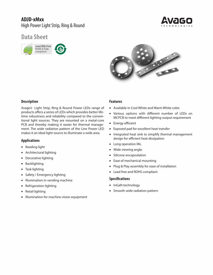
ADJD-xMxxHigh Power Light Strip, Ring & Round
Data Sheet
Description
Avago’s Light Strip, Ring & Round Power LEDs range of products offers a series of LEDs which provides better life-time robustness and reliability compared to the conven-tional light sources. They are mounted on a metal-core PCB and thereby making it easier for thermal manage-ment. The wide radiation pattern of the Line Power LED makes it an ideal light source to illuminate a wide area.
Applications
� Reading light
� Architectural lighting
� Decorative lighting
� Backlighting
� Task lighting
� Safety / Emergency lighting
� Illumination in vending machine
� Refrigeration lighting
� Retail lighting
� Illumination for machine vision equipment
Features
� Available in Cool White and Warm White color.
� Various options with different number of LEDs on MCPCB to meet different lighting output requirement
� Energy efficient
� Exposed pad for excellent heat transfer
� Integrated heat sink to simplify thermal management design for efficient heat dissipation
� Long operation life.
� Wide viewing angle.
� Silicone encapsulation
� Ease of mechanical mounting
� Plug & Play assembly for ease of installation
� Lead free and ROHS compliant
Specifications
� InGaN technology
� Smooth wide radiation pattern

2
Package Dimensions
Light Strip
ADJD-xM00 (3 LEDs)
ADJD-xM01 (3 LEDs)
ADJD-xM10 (4 LEDs)
ADJD-xM21 (6 LEDs)
Notes:1. All dimensions are in millimeters.2. Tolerance is ±0.1mm unless otherwise specified.

3
Notes:1. All dimensions are in millimeters.2. Tolerance is ±0.1mm unless
otherwise specified.66.80
120˚R1.70
Ø88.00
Ø140.00
Ø4.00
49.50
Ø110.00
290.01.6
290.0R1.63.0
35.0
14.9
72.5
24.2
145.0
72.50
145.00
290.0
35.0017.50
16.2032.20
R1.6
ADJD-xM30 (9 LEDs)
ADJD-xM40 (12 LEDs)
Light Ring & Round
ADJD-xMR0 (7 LEDs)
ADJD-xMR3 (8 LEDs)

4
Device Selection Guide (TJ = 25°C) [1]
Module
Type Color No. of LEDs Part Number
Luminous Flux, Φv [2,3]
(lm)
Test
Current Dice
TechnologyMin. Typ. Max. (mA)
Strip
Cool White
3 ADJD-WM00
56.0 80.0 124.0 350 InGaN
3 ADJD-WM01
4 ADJD-WM10
6 ADJD-WM21
9 ADJD-WM30
12 ADJD-WM40
Warm White
3 ADJD-YM00
56.0 70.0 95.0 350 InGaN
3 ADJD-YM01
4 ADJD-YM10
6 ADJD-YM21
9 ADJD-YM30
12 ADJD-YM40
Round Cool White 7 ADJD-WMR056.0 80.0 124.0 350 InGaN
Ring 8 ADJD-WMR3
Round Warm White 7 ADJD-YMR056.0 70.0 95.0 350 InGaN
Ring 8 ADJD-YMR3
Notes:1. Applicable to a single unit of LED only. Data are based on ASMT-Mxx4 component level device only. 2. �V is the total luminous flux output as measured with an integrating sphere at 25ms mono pulse condition.3. Flux tolerance is ±10 %.
Note:1. Please refer to Page 10 for selection details.
Table 1.
x2x3
No. of
LEDs
Module
Type Resistor
Driving
Condition
00 3 Strip No Current
01 3 Strip Yes Voltage
10 4 Strip No Current
21 6 Strip Yes Voltage
30 9 Strip No Current
40 12 Strip No Current
R0 7 Round No Current
R3 8 Ring No Current
Part Numbering System
ADJD – x1 M x2x3 – N x4 x5 x6 x7
Packaging Option
Color Bin Selection
Maximum Flux Bin Selection
Minimum Flux Bin Selection
Please refer to Table 1
Color
W - Cool White
Y - Warm White

5
Absolute Maximum Ratings at TA = 25°C
Parameter ADJD- xM00 xM10 xMR0 xM40 xMR3 xM30 xM01 xM21 Units
DC Forward Current [1] 350 350 350 700 700 1050 mA
Input Voltage [2] 12 12 V
Operating Ambient Temperature Range -40 to +85 °C
Storage Temperature Range -40 to +100 °C
Note:1.DC forward current.2.Input Voltage only applicable for ADJD-xM01 and ADJD-xM21.
Optical Characteristics at 350 mA (TJ = 25°C) [1]
Part Number
No. of
LEDs Color
Correlated Color
Temperature, CCT
(Kelvin)
Viewing Angle 2θ½ [2]
(Degrees)
Luminous Efficiency
(lm/W)
Min Max Typ Typ
ADJD-WM00 3
Cool White 4000 10000 110 65
ADJD-WM01 3
ADJD-WM10 4
ADJD-WM21 6
ADJD-WM30 9
ADJD-WM40 12
ADJD-WMR0 7
ADJD-WMR3 8
ADJD-YM00 3
Warm White 2600 4000 110 57
ADJD-YM01 3
ADJD-YM10 4
ADJD-YM21 6
ADJD-YM30 9
ADJD-YM40 12
ADJD-YMR0 7
ADJD-YMR3 8
Notes:1. Applicable to a single unit of LED only. Data are based on ASMT-Mxx4 component level device only. 2. �½ is the off-axis angle where the luminous intensity is ½ the peak intensity.
Electrical Characteristic at 350 mA (TJ = 25 °C) [1]
Dice Type
Forward Voltage VF
(Volts)
Input Voltage Vin [2]
(Volts)
Min. Typ. Max. Typ. Max.
InGaN 2.8 3.5 4.0 10.2 12.0
Notes:1. Applicable to a single unit of LED only. Data are based on ASMT-Mxx4 component level device only. 2. Input Voltage only applicable for ADJD-xM01 and ADJD-xM21.

6
Pin 2 Pos +
Pin 1 Neg -
Pin 2 Pos +
Pin 1 Neg -
Pin 1 2
+-
Pin 2 Pos + Pin 1 Neg -
VIn
Electrical Configuration
ADJD-xM00 (3 LEDs)
Pin Number[A] Configuration
1 Neg-
2 Pos+
ADJD-xM10 (4 LEDs)
ADJD-xMR3 (8 LEDs)
*Note: A. The above configuration is only applicable for ADJD-xM00 / ADJD-xM10 and ADJD-xMR3
ADJD-xMR0 (7 LEDs)
*Note: Connector is not applicable for ADJD-xMR0

7
ADJD-xM01 (3 LEDs)
Pin Number [C] Configuration
1 Neg-
2 NC
3 NC
4 Pos+
Pin Number [B] Configuration
1 Neg-
2 Pos+
ADJD-xM21 (6 LEDs)
*Note: B. The above configuration is only applicable for ADJD-xM01 and ADJD-xM21
ADJD-xM30 (9 LEDs)
ADJD-xM40 (12 LEDs)
*Note: C. The above configuration is only applicable for ADJD-xM30 and ADJD-xM40
Recommend Female Connector:
Tyco 173977-2
Pin 2 Neg -
Pin 1 Pos+
Pin 2 Neg -Pin 1 Pos+
Pin 1 2
+ -
Pin 1 Neg –Pin 2 NC
Pin 4 Pos +Pin 3 NC
Pin 4 Pos +Pin 3 NC
Pin 1 Neg –Pin 2 NC
Pin 1 2
+-
Pin 3 4
NC NC

8
0.0
0.1
0.2
0.3
0.4
0.5
0.6
0.7
0.8
0.9
1.0
380 430 480 530 580 630 680 730 780
WAVELENGTH - nm
RELAT
IVE
INTENSI
TY
WARM WHITECOOL WHITE
0
0.2
0.4
0.6
0.8
1
1.2
1.4
0 50 100 150 200 250 300 350 400 450 500
DC FORWARD CURRENT - mA
RELAT
IVE
LUM
INOUS F
LUX
(NORMAL
IZED
AT
350 mA)
0
0.1
0.2
0.3
0.4
0.5
0.6
0.7
0.8
0.9
1
-90 -60 -30 0 30 60 90
ANGULAR DISPLACEMENT - DEGREES
NO
RMA
LIZED
INTENSI
TY
0
50
100
150
200
250
300
350
400
450
500
0 0.5 1 1.5 2 2.5 3 3.5 4
FORWARD VOLTAGE - V
FOR
WA
RD
CU
RR
ENT
- mA
0.0
0.2
0.4
0.6
0.8
1.0
1.2
1.4
0.00001 0.0001 0.001 0.01 0.1 1 10 100
PULSE DURATION, tp - sec
PU
LSE CU
RR
ENT,
I P - A
D =0.050.100.250.501.00
0.0
0.2
0.4
0.6
0.8
1.0
1.2
1.4
0.00001 0.0001 0.001 0.01 0.1 1 10 100
PULSE DURATION, tp - sec
PU
LSE CU
RR
ENT,
I P - A
D =0.050.100.250.501.00
D=tpT
tpIF
TD=
tpT
tpIF
T
Figure 1. Relative Intensity vs. Wavelength. Figure 2. Relative Luminous Flux vs. Mono Pulse Current.
Figure 3. Forward Current vs. Forward Voltage. Figure 4. Radiation Pattern.
Figure 6. Maximum pulse current vs. ambient temperature. Derated based
on TA = 85°C, R�J-A = 50°C/W.
Figure 5. Maximum pulse current vs. ambient temperature. Derated based
on TA = 25°C, R�J-A = 50°C/W.

9
0.0
0.1
0.2
0.3
0.4
0.5
0.6
0.7
0.8
0.9
1.0
1.1
1.2
-50 -25 0 25 50 75 100 125
JUNCTION TEMPERATURE, TJ - °C
RELA
TIV
E LI
GH
T O
UTP
UT
(NO
RMA
LIZED
AT
25°C
)
WARM WHITE
COOL WHITE
0
50
100
150
200
250
300
350
400
0 20 40 60 80 100 120 140
AMBIENT TEMPERATURE, TA - °C
MA
X A
LLO
WAB
LE DC CU
RR
ENT
- mA
R�J-A = 30°C/W
R�J-A = 40°C/W
R�J-A = 50°C/W
0
50
100
150
200
250
300
350
400
0 20 40 60 80 100 120 140
METAL SLUG TEMPERATURE, TMS - °C
MA
X A
LLO
WAB
LE DC CU
RR
ENT
- mA
R�J-MS = 10°C/W
Figure 9. Maximum Forward Current vs. Metal Slug Temperature.
Derated based on TJMAX = 125°C, R�J-MS = 10°C/W.
Figure 10. Recommended Reflow Soldering. Figure 11. Recommended soldering land pattern.
(Acc. to J-STD-020C)
217°C200°C
60 - 120 SEC.
6°C/SEC. MAX.
3°C/SEC. MAX.
3°C/SEC. MAX.
150°C
255 - 260°C
100 SEC. MAX.
10 - 30 SEC.
TIME
TEMPERA
TURE
10.70±0.10
8.40±0.10
3.1±0.10
5.08±0.10
1.00±0.10
17.00±0.20
Notes:1. For detail information on reflow soldering of Avago surface mount LEDs, do refer to Avago Application Note AN1060 Surface Mounting SMT LED
Indicator Components.2. All parametric charts are only applicable to ASMT-Mxx4 component level device only.
Figure 8. Maximum Forward Current vs. Ambient Temperature.
Derated based on TJMAX = 125°C, R�J-A = 30°C/W, 40°C/W and 50°C/W.
Figure 7. Relative Light Output vs. Junction Temperature.

10
Color Bin Selections [x6]
Individual tray will contain parts from one color bin selection only.
Cool White
O Full Distribution
A A only
B B only
C C only
D D only
E E only
F F only
G G only
H H only
L A and G only
M B and H only
N A and C only
P B and D only
Q E and C only
R F and D only
S G and H only
U E and F only
W C and D only
Z A and B only
1 A, B, C and D only
2 G, H, A and B only
4 C, D, E and F only
Warm White
O Full Distribution
A A only
B B only
C C only
D D only
E E only
F F only
N A and C only
P B and D only
Q E and C only
R F and D only
U E and F only
W C and D only
Z A and B only
1 A, B, C and D only
4 C, D, E and F only
Flux Bin Limit [x4, x5]
Bin
Luminous Flux (lm) at IF = 350mA
Min. Max.
K 56.0 73.0
L 73.0 95.0
M 95.0 124.0
Notes:1. Tolerance for each bin limits is ±10 %.2. Applicable to a single unit of LED ASMT-Mxx4 only.
Option Selection Details
ADJD - x1 M x2x3 - N x4 x5 x6 x7
x4 – Minimum Flux Binx5 – Maximum Flux Binx6 – Color Bin Selectionx7 - Packaging Option.

11
Color Bin Limit
Cool Color Limits
White (Chromaticity Coordinates)
Bin A X 0.367 0.362 0.329 0.329 Y 0.400 0.372 0.345 0.369
Bin B X 0.362 0.356 0.329 0.329 Y 0.372 0.330 0.302 0.345
Bin C X 0.329 0.329 0.305 0.301 Y 0.369 0.345 0.322 0.342
Bin D X 0.329 0.329 0.311 0.305 Y 0.345 0.302 0.285 0.322
Bin E X 0.303 0.307 0.283 0.274 Y 0.333 0.311 0.284 0.301
Bin F X 0.307 0.311 0.290 0.283 Y 0.311 0.285 0.265 0.284
Bin G X 0.388 0.379 0.362 0.367 Y 0.417 0.383 0.372 0.400
Bin H X 0.379 0.369 0.356 0.362 Y 0.383 0.343 0.330 0.372
Tolerance: ± 0.01
Warm Color Limits
White (Chromaticity Coordinates)
Bin A X 0.452 0.488 0.470 0.438 Y 0.434 0.447 0.414 0.403
Bin B X 0.438 0.470 0.452 0.424 Y 0.403 0.414 0.384 0.376
Bin C X 0.407 0.418 0.452 0.438 Y 0.393 0.422 0.434 0.403
Bin D X 0.395 0.407 0.438 0.424 Y 0.362 0.393 0.403 0.376
Bin E X 0.381 0.387 0.418 0.407 Y 0.377 0.404 0.422 0.393
Bin F X 0.373 0.381 0.407 0.395 Y 0.349 0.377 0.393 0.362
Tolerance: ± 0.01
0.24
0.26
0.28
0.30
0.32
0.34
0.36
0.38
0.40
0.42
0.44
0.24 0.26 0.28 0.30 0.32 0.34 0.36 0.38 0.40 0.42 0.44
Y - COO
RD
INA
TE
X - COORDINATE
BC
E D
A
F
4.5k
7k
10k
4.0k
G
H
Black Body Curve5.6k
0.32
0.34
0.36
0.38
0.40
0.42
0.44
0.46
0.48
0.34 0.36 0.38 0.40 0.42 0.44 0.46 0.48 0.50 0.52
X - COORDINATE
Y - COO
RD
INA
TE
B
C
E
D
A
F
3.5k
4.0k
2.6k3.0k
Black Body Curve
Packaging Option [x7]
Selection Option
0 Tray
Example
ADJD-WM40-NKMZ0
ADJD-MW40-Nxxxx – Cool White, 12 LEDs Strip x4 = K – Minimum Flux Bin K x5 = M – Maximum Flux Bin M x6 = Z – Color Bin A and B onlyx7 = 0 – Tray Option
Figure 13. Color bins (Warm White).Figure 12. Color bins (Cool White).

For product information and a complete list of distributors, please go to our web site: www.avagotech.com
Avago, Avago Technologies, and the A logo are trademarks of Avago Technologies Limited in the United States and other countries.
Data subject to change. Copyright © 2005-2010 Avago Technologies Limited. All rights reserved.
AV02-1120EN - June 25, 2010
Handling Precaution
The encapsulation material of the product is made of silicone for better reliability of the product. As silicone is a soft material, please do not press on the silicone or poke a sharp object onto the silicone. These might damage the product and cause premature failure. During assembly or handling, the unit should be held on the body (white plastic).
DISCLAIMER: AVAGO’S PRODUCTS AND SOFTWARE ARE NOT SPECIFICALLY DESIGNED, MANUFACTURED OR AU-THORIZED FOR SALE AS PARTS, COMPONENTS OR ASSEMBLIES FOR THE PLANNING, CONSTRUCTION, MAINTENANCE OR DIRECT OPERATION OF A NUCLEAR FACILITY OR FOR USE IN MEDICAL DEVICES OR APPLICATIONS. CUSTOMER IS SOLELY RESPONSIBLE, AND WAIVES ALL RIGHTS TO MAKE CLAIMS AGAINST AVAGO OR ITS SUPPLIERS, FOR ALL LOSS, DAMAGE, EXPENSE OR LIABILITY IN CONNECTION WITH SUCH USE.