Embed Size (px)
Citation preview

Autonomous Following RObotInitial Design Review
James Tse (Leader)Wei Dai
Travis FreckerPeter Verlangieri
Professor John JohnsonECE 189A Fall 2012

Initial Design Review: Project Description
● Original design: a robot that autonomously draws fields. ○ Issues:
■ Locality■ Time constraint■ Expensive

Initial Design Review: Project Description (II)
● Revisited idea: a robot that follows and re-draw existing lines.
● Applications: ○ Redrawing existing sports fields, e.g.
basketball, tennis, football, soccer○ Repainting fading street lines○ Perimeter security

Initial Design Review: Project Description (III)
● Base proof of concept goals: ○ Following a line with high precision and accuracy.○ Using a set of rules to be able to find and trace
existing lines, without user input.
Initial Design Review: Project Description (IV)
● Combination of sensors and positioning systems:○ IR Sensors○ Sonar○ Reflectance Sensor Array○ Digital Compass○ Rotary Encoders
● Concept is to load the robot with as much data as possible; if we need it, then we will have it.

James (leader) - processor, optical sensor, camera, powerWei - PCB, digital compass, powerTravis - mechanical - servo, reflective sensor, powerPeter - mechanical - motor controls, sensor interface, rotary encoders
All: processor, chassis design/fabrication
Initial Design Review: Subsystem Development Responsibility

Initial Design Review: Block diagram
Initial Design Review: Basic Design
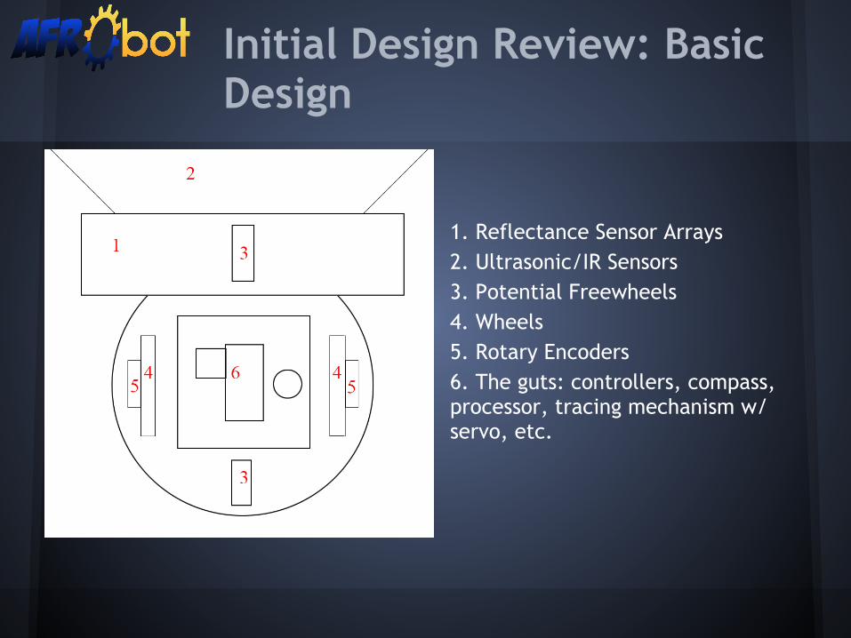
1. Reflectance Sensor Arrays2. Ultrasonic/IR Sensors3. Potential Freewheels4. Wheels5. Rotary Encoders6. The guts: controllers, compass, processor, tracing mechanism w/ servo, etc.

Parts: Digital Compass
● Devantech CMPS03 Magnetic Compass Module○ 0.1 degrees of resolution and 3 to 4 degrees of
accuracy○ Outputs heading via PWM or I2C○ 5V voltage only○ Specifically designed for use in robots as navigation
aid○ $44.61 @ www.robotshop.com

Parts: Reflectance Sensor Arrays
● QTR-8RC Reflectance Sensor Array○ Sensing distance: 3-9.5mm○ Interface directly to GPIO of microcontroller○ Operating voltage: 3.3-5.0 V○ $14.95 @ www.pololu.com
● GP2A240LCS0F○ Sensing distance: 2-22mm○ Interface directly to GPIO of microcontroller○ Operating voltage: 4.75-5.25 V○ $5.20 @ www.digikey.com

● HS-55 Micro Servo Motor○ Speed (sec/60°): 0.14○ Torque (Kg-cm/Oz-in): 1.3/18○ Size (mm): 23 x 12 x 24○ Weight (g/oz):8/0.28○ $9.99 @ www.robotshop.com
Parts: Servo Motor

● Maxbotix LV-MaxSonar-EZ0○ Object avoidance○ Detects objects of distance from 0 to 6.45 meters.
(0 to ~21 ft).○ RS-232○ 2.5 - 5.5V, at 5V - 3mA○ $26.95 @ www.robotshop.com
Parts: Ultrasonic Sensor

● Sharp GP2Y0A21YK0F IR Range Sensor○ Object avoidance ○ Detects objects of distance from 10cm to 80cm (4''
to 32'').○ Output: Analog to Digital ○ 4.5 - 5.5V, supply current: 30mA○ $11.75 @ www.digikey.com
Parts: IR sensor
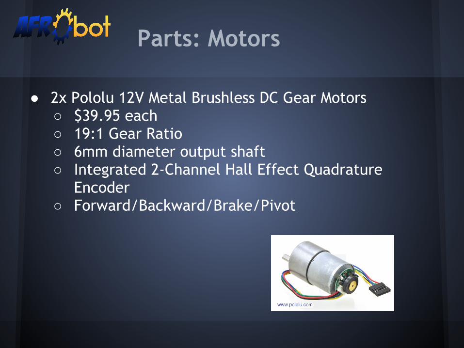
● 2x Pololu 12V Metal Brushless DC Gear Motors○ $39.95 each○ 19:1 Gear Ratio○ 6mm diameter output shaft○ Integrated 2-Channel Hall Effect Quadrature
Encoder○ Forward/Backward/Brake/Pivot
Parts: Motors

● Rotary encoders provide feedback to the microprocessor via GPIO.
● Frequency of output signal provides speed of the motor and distance traveled.
● Using encoders on both the right and left wheel allows the microprocessor to calculate and correct offset in traveling in the straight line.
● 64 counts-per-revolution.● Vcc (3.5-20V)● Included in motor● Well documented by Pololu
Parts: Rotary Encoders

● Solarbotics L298 Compact Dual Motor Driver Kit○ $18.28○ 6-50V Output○ Up to 4A total output current○ Allow us to independently control both motors with
a single chip○ Well documented○ Used by past 189 Capstone Projects
Parts:Motor Controller

Initial Design Review: Preliminary Bill of Materials
Quantity Part Unit Cost Total Cost
1 Digital compass $44.61 $44.61
2 Reflectance sensor array $14.94 $29.88
1 Ultrasonic sensor $26.95 $26.95
3 IR sensor $11.75 $35.25
2 Motor and rotary encoder combo $39.95 $79.90
1 Motor controller $18.28 $18.28
1 Servo motor $9.99 $9.99
Total $244.86
● Motor control ○ Keeping the bot in a straight path to avoid rough
traces.● Reflectance Sensor Array
○ Being able to detect a line in an outdoor environment and use that data to accurately position AFRObot. ■ Currently looking into camera modules.
Initial Design Review: Critical Elements

Initial Design Review: Schedule
11/18 - 11/24PCB layout - M5 (11/18 - 12/07)
Low level hardware implementation - M4 (11/11 - 11/28)
Verilog functional and timing simulations
Details of intended software structure
Lowest-level hardware-software interaction
MAKEPART
11/14 - 12/01Milestone #4 - (11/28)
PCB layout - Milestone #5 (11/18 - 12/07)
12/02 - 12/08Critical Design Review - (12/03)
Milestone #5 - (12/07)
12/9 - 12/15Finals
12/16 - 01/6/2013WINTER BREAK!!!
10/21 - 10/27
IDR - (10/24)
Purchase parts - (10/24)
System-level Design - M3 (10/24 - 10/31)
Component selection - BOM
Collection of data sheets
Software!
Develop parts test plan - (10/24 - 11/03)
10/28 - 11/03
Milestone #3 - (10/31)
Test parts (10/28 - 11/03)
11/04 - 11/10
Preliminary Design Review - (11/05)
11/11 - 11/17
Low level hardware implementation - M4 (11/11 - 11/28)
Verilog functional and timing simulations
lowest-level hardware-software interaction
MAKEPART

Questions?Suggestions?


![[ , ] Autonomous Human Robot Interactive Skills](https://img.pdfslide.us/doc/110x75/577cc35f1a28aba71195d883/-autonomous-human-robot-interactive-skills.jpg)