Embed Size (px)
Citation preview

1
Automotive Simulation ModelsReal-Time Models /
2019
Automotive Simulation Models (ASM)Tool suite for simulating the engine, vehicle dynamics, electrical system, and traffi c environment
Highlights
� Open MATLAB®/Simulink® models
� For ECU testing and function development
� Intuitive graphical parameterization with road
and scenario creation in ModelDesk
Application AreasThe Automotive Simulation Models (ASM) are a tool suite
of open Simulink models for the real-time simulation of
passenger cars and trucks as well as their components. They
are used as plant models for the development and testing
of engine controls, vehicle dynamics controls, on-board
power electronics and driver assistance systems.
The ASMs are typically used on a dSPACE SCALEXIO for
hardware-in-the-loop (HIL) testing of electronic control units
(ECUs) or during the design phase of controller algorithms
for early validation by offl ine simulation.
Key Benefi tsAll the Simulink blocks in the models are visible, so it is easy
to add or replace components with custom models to adapt
the properties of modeled components perfectly to indi-
vidual requirements. The ASMs’ standardized interfaces
make it easy to expand a single model such as an engine
or body, or even create a whole virtual vehicle. Roads and
driving scenarios can be easily and intuitively created using
graphical tools with preview and clear visualization.
Modular ConceptThe ASM concept consists of coordinated, combinable models
of automotive components. There is a vehicle model with
a trailer, plus other ASMs for gasoline, diesel and hybrid
engines, exhaust systems, turbochargers, brake hydraulics,
electrical systems, electric motors, environment sensors,
roads and traffi c. The ASMs support a whole range of
simulations from individual components to complex virtual
traffi c scenarios.
Offl ine and Online SimulationThe ASMs can be used in combination with real controllers
in a hardware-in-the-loop environment (HIL or online mode),
or for model-in-the-loop simulations (PC or offl ine mode).
The same model confi gurations and parameters can be used
seamlessly throughout all the steps from function develop-
ment to ECU testing.

2
Automotive Simulation ModelsReal-Time Models /
2019
Main Features and Benefi ts
Feature Description Benefi t
Open Simulink models � Almost all models are open down to the Simulink block level � Custom models can easily be added or used to replace model components
ModelDesk � Graphical user interface with parameter and simulation management
� Easy, intuitive parameterization and seamless simulation handling
Online simulation � Real-time simulation on real-time hardware � Hardware-in-the-loop simulations with ECUs
Offl ine simulation � Simulations as early as the design phase � Controller validation in early development stages
ASMSignalBus � Simulation signals are part of a structured Simulink signal bus � Standardized and fast access to model variables
Online tunable parameters � Direct parameter access during real-time simulations � Online parameter optimizations and behavior studies
Model interoperability � ASM models are easy to combine to create a virtual vehicle � An entire virtual vehicle can be simulated
Order Information
Classifi cation Type Order Number
Packages ASM – Gasoline Engine Basic Simulation Package � Please inquire
ASM – Gasoline Engine Simulation Package � Please inquire
ASM – Diesel Engine Simulation Package � Please inquire
ASM – Gasoline Engine InCylinder Simulation Package � Please inquire
ASM – Diesel Engine InCylinder Simulation Package � Please inquire
ASM – Vehicle Dynamics Simulation Package for VEOS � Please inquire
ASM – Vehicle Dynamics Simulation Package � Please inquire
ASM – Truck and Trailer Simulation Package � Please inquire
Libraries ASM – Turbocharger � ASM_L_TC
ASM – Drivetrain Basic � ASM_L_DTB
ASM – Electric Components � ASM_L_EC
XSG – Electric Component � XSG_EC_LIB
ASM – Brake Hydraulics � ASM_L_BH
ASM – Diesel Exhaust System � ASM_L_DEXH
ASM – Traffi c � ASM_L_TRF
ASM – Pneumatics � ASM_L_PNEU
ASM – KnC � ASM_L_KNC
Relevant Software and Hardware
Software
Required Integrated development environment � MATLAB/Simulink1) from MathWorks� Simulink® Coder™ (formerly Real-Time Workshop®) 3)
� Simulink Accelerator2)
dSPACE implementation software � Real-Time Interface (RTI)3)
dSPACE experiment software � ControlDesk 3)
Additional software � Microsoft® Excel®
Operating system � www.dspace.com/go/os_compatibility
Hardware
Required Recommended system � Intel® Core™ i7 Processor� Memory ≥ 8 GB RAM � Dual-head graphics accelerator card matching the requirements
of MotionDesk4)
SCALEXIO or dSPACE Simulator (equipped with DS1006 Processor Board or DS1007 PPC Processor Board), MicroLabBox
1) MATLAB®/Simulink® Student Suite does not support Automotive Simulation Models (ASM).2) Offl ine simulations only3) Online simulations only4) Graphics accelerator required for MotionDesk which is part of the ASM Vehicle Dynamics Simulation Package.
More details on graphics card requirements and compatibility at www.dspace.com/go/mdhwrequ

3
Automotive Simulation ModelsReal-Time Models /
2019
Introduction Why Use Simulation? Why Use Models?In model-based design (MBD), simulation is a widely used
and proven method. It is applied to test and validate control
algorithms in a virtual world instead of on the real controlled
device. For automotive applications this ranges from simu-
lated individual components, such as engines, to complete
virtual vehicles, up to virtual environments consisting of a
vehicle and its surrounding traffic, traffic signs, and so on.
Virtualized controlled device (vehicle) and controller (ECU) in a control loop.
ASM Simulation Tool SuiteThe Automotive Simulation Models (ASM) from dSPACE are
a simulation tool suite covering four application areas:
combustion engines, electric components, vehicle dynamics
and the traffic environment. These ready-to-use simulation
models exactly represent the behavior of the controlled de-
vices. The ASM tool suite is designed to fully comply with the
MBD approach. All models are implemented with MATLAB®/
Simulink®.
Tool suite for simulating engines, electric components, vehicle dynamics and traffic.
Simulation PlatformsThe support of multiple platforms allows for seamless
simulation processes from model-in-the-loop (MIL) to soft-
ware-in-the-loop (SIL) to hardware-in-the-loop (HIL). The
ASM tool suite can be executed on different simulation
platforms: SCALEXIO, dSPACE Simulator, VEOS, or a PC
running MATLAB/Simulink. Depending on the platform,
simulations can be performed either with the controller
software or the controller hardware (ECU) in the control
loop. In either case the simulation model stays the same.
The ASM simulation tool suite supports mutiple simulation platforms.

4
Automotive Simulation ModelsReal-Time Models /
2019
Supports Model-Based Design� Real-time-capable Simulink models
� Provides access to internal modeling details, down
to block level
� Supports all stages of controller software development
(MIL, SIL, HIL)
� Soft-ECU network
� Signal interfaces for automotive applications
Ready-to-use Off-the-Shelf (OTS) Models� One integrated tool chain for parameterization,
validation and test automation
� Open documentation, including mathematical equations
� Supports migration, including between MATLAB releases
� Worldwide customer base and mature models
Philosophy
Complete ASM Product Portfolio� Supports all automotive-relevant modeling areas
� Easily combinable models for building virtual vehicles
� Different levels of model complexity (e.g. mean value,
physical) for all controller design and test use cases
Comprehensive Engineering and HIL Knowledge� The one-stop supplier for all HIL-relevant tasks
� Customer training and worldwide support
� Combination of OTS models and custom specifi c model engineering
5
Automotive Simulation ModelsReal-Time Models /
2019
Combustion Engine Simulation Real-time models for diesel and gasoline engine simulation
Simulation Packages and Models� Diesel and gasoline engines
� Mean-value and InCylinder plant models
� Physical turbocharger
� Diesel aftertreatment system
The TaskTest the diagnosis capabilities of a lambda-based exhaust
aftertreatment control system.
Example Use Case: Optimal Lambda Control
Graphical parameterization of the engine model for precise simulations.
The ChallengeAs part of the onboard diagnostics (OBD) system, the lamb-
da sensor output in the engine’s exhaust path underlies
different diagnosis routines, which have to be validated in
a HIL environment. Several chemical reactions have to be
ASM considers the effects correlated to the oxygen storage
capacity of the aftertreatment component as well as effects
based on backward reactions within the catalyst itself. Prior
knowledge on the chemical reactions and relevant effects
is used to develop a phenomenological modeling approach
based on oxygen storage and release rates within the cata-
lyst to generate a lambda sensor output signal that captures
effects used in the diagnosis system to identify aging after-
treatment systems, for example.
A/F
O2 back reaction
O2 purging
O2 filling
pre-catalyst
post-catalyst
O2 storage effect
14.7
rich-to-lean A/F step lean-to-rich A/F step
considered in a three-way-catalyst sys-
tem, and the detailed simulation of all
related effects drastically increases the
calculation time and parameterization
effort. Therefore, the dominant effects
for testing OBD-relevant ECU func-
tions must be identifi ed, while taking
into consideration the data sources
available to the user to provide a real-
time-capable solution that is ready for
use in HIL projects.
The SolutionThe three-way-catalyst simulation from

6
Automotive Simulation ModelsReal-Time Models /
2019
Schematic of the air system.
ASM Gasoline Engine Basic Basic mean-value engine model with combustion torque modulation
Simulation Model CharacteristicsThe actual physical engine characteristics are represented
by a mean-value engine model with crank-angle-based
torque generation, dynamic manifold pressure, temperature
calculation, and an injection model. To simulate the engine
in an automotive system (car or truck), the engine model
incorporates a longitudinal drivetrain model with manual
and automatic transmission, a clutch, a torque converter, a
starter, and a test bench mode. Models for the environment
and driver complement the virtual powertrain.
Features at a Glance
�� Up to 20-cylinder gasoline applications
�� Up to 4 injections per cylinder per cycle
�� Intake manifold with calculation of intake manifold
pressure and temperature
�� Map-based turbocharger for boost pressure
calculation
�� Fuel injection system with fuel tank model
�� Wall film evaporation taken into account
�� Longitudinal driver for standard cycles (FTP75, NEDC,
J10-15, …)
�� Simulation with real ECU in hardware-in-the-loop (HIL)
system and simulated soft ECU in model-in-the-loop
simulation
�� Start/stop system support
More detailed information available
�� www.dspace.com/asm
Air path FuelsystemIntake manifoldThrottle
Engine-cooling
Engine-combustion
qinj
nEngine
Trqeng
Turbocharger
Main Model Components�� Air system
�� Fuel system
�� Piston engine
�� Turbocharger
�� Drivetrain (basic)
�� Vehicle dynamics (longitudinal)
�� Environment (basic)
�� Soft ECU

7
Automotive Simulation ModelsReal-Time Models /
2019
Compressor
Turbine
Wastegate
EGRvalve
VTG
EGR
Air path
TurbochargerFuelsystemdirectinjection
Fuelsystemmanifoldinjection
Intake manifoldThrottleIntercooler
Exhaust manifold
Engine-cooling
Engine-combustion
nTC
PosWGT
PosEGR
PosVTG
PosThr
EGRcooler
qinj
neng
Trqeng
qinj
ASM Diesel/Gasoline EngineMean-value engine models with combustion torque modulation
Features at a Glance�� Up to 20-cylinder diesel/gasoline applications
�� Map-based turbocharger for boost pressure calculation
�� Gasoline fuel injection system: direct injector and
intake manifold injector
�� Natural gas fuel supply systems
�� Gasoline engine with homogenous and stratified
combustion modes
�� Gasoline engine with evaporation system support
�� Gasoline exhaust system including dynamic three way
catalyst simulation with respect to oxygen storage
capacity
�� Common rail system including rail, fuel tank as well as
Simulation Model CharacteristicsThe physical engine characteristics are represented by a
mean-value engine model with crank-angle-based torque
modulation, dynamic manifold pressure, temperature cal-
culation, and several fuel injection models. A soft ECU is
included for scenarios where a
real ECU is not available, for
example, in offline simulation.
To simulate the engine in an
automotive system (car or truck),
the engine model incorporates
a longitudinal drivetrain model
with manual and automatic
transmission, a clutch, a torque
converter, a starter, and a test
bench mode. Models for the
environment and driver comple-
ment the virtual powertrain.
Main Model Components�� Air system
�� Fuel system
�� Piston engine
�� Aftertreatment systems
�� Turbocharger
current or crankbased high pressure pump
�� Diesel fuel injection systems: direct injector,
unit injector, unit pump
�� Up to 8 direct injections and 4 port injections per
cylinder per cycle
�� Diesel exhaust system including diesel oxidation catalyst
(DOC) and diesel particulate filter (DPF)
�� High-pressure and low-pressure exhaust-gas recirculation
(EGR) of exhaust and unburned air with EGR cooler
�� Start/stop system support
�� Longitudinal driver for standard cycles (WLTC, FTP75,
NEDC, J10-15, …)
More detailed information available
�� www.dspace.com/asm
Schematic of the air system.
�� Drivetrain (basic)
�� Vehicle dynamics (longitudinal)
�� Environment (basic)
�� Soft ECU

8
Automotive Simulation ModelsReal-Time Models /
2019
Compressor
Turbine
Wastegate
EGRvalve
VTG
EGR
Air path
Turbocharger
Intake manifoldThrottleIntercooler
Exhaust manifold
EnginecoolingnTC
PosWGT
PosEGR
PosVTG
PosThr
EGRcooler
neng
Trqeng
Engine combustion
Intake valve Fuelsystemdirectinjection
Fuelsystemmanifoldinjection
qinj
qinj
Exhaust valve
ASM Diesel/Gasoline Engine In-CylinderReal-time engine models with in-cylinder pressure and temperature simulation
Main Model Components�� Air system
�� Fuel system
�� Valve system
�� Piston engine
�� Diesel aftertreatment system
�� Turbocharger
�� Drivetrain (basic)
�� Vehicle dynamics (longitudinal)
�� Environment (basic)
�� Soft ECU
Features at a Glance�� Simulation of in-cylinder pressure and temperature in
real time: for example, in response to injection or
variable valve timing
�� Diesel applications with up to 20 cylinders with common
rail and turbocharger for real-time simulation.
�� Up to 8 direct injections and 4 port injections per cylinder
per cycle
�� Gasoline applications with up to 20 cylinders with direct
or port injection and turbocharger for real-time simulation.
�� Gasoline exhaust system, including dynamic three-way
catalyst simulation with respect to oxygen storage
capacity
�� Diesel: multiple injection patterns such as pre-, main
and post-injection
�� Gas exchange simulation related to the lift of the intake
and exhaust valves
�� Fuel injection systems: common rail injector (Diesel),
direct or port injection (Gasoline)
�� Exhaust-gas recirculation (EGR) of exhaust and fresh air
with EGR cooler
�� Start/stop system support
�� Simulation of parallel intake and exhaust air paths for
V-type engine
Simulation Model CharacteristicsThe ASM Diesel Engine In-Cylinder Simulation Package and
the Gasoline Engine In-Cylinder Simulation Package are open
Simulink models for developing and testing electronic con-
trol units (ECUs) with engine management based on the in-
cylinder pressure. The models simulate in-cylinder pressure in
real time by means of a zero-dimensional thermodynamic
approach. The diesel combustion process simulation can
handle multiple injection patterns such as pre-, main and post-
injection. In the combustion process, gas exchange simulation
is related to the lift of the intake and exhaust valves. The gas-
dynamical behavior of the air path and exhaust path is imple-
mented as a mean value system with manifold pressure, tem-
perature, and mass calculation. The inlet and exhaust valves are
modeled as isentropic orifices. They can handle variable valve
timing (VVT), variable valve lift
(VVL), and the simulation of
engines without a camshaft. To
simulate the engine within an
automotive system (car or truck),
the engine model incorporates
a basic longitudinal drivetrain
model. Models for the envi-
ronment and driver comple-
ment the virtual power train.
Schematic of the air system.
More detailed information
available
�� www.dspace.com/asm

9
Automotive Simulation ModelsReal-Time Models /
2019
ASM TurbochargerPhysical turbocharger model
Main Model Components� Compressor
� Turbine
� Wastegate valve
� Shaft
Features at a Glance� Calculates air path with the precision of a physical model
� Wastegate valve and variable turbine geometry (VTG)
� Turbocharger state calculation based on common
manufacturer maps including heat loss calculation
� Alternative to map-based model with easy switching
between map-based and physical approach
� Support of diesel and gasoline engine models
� Support of SAE J922 turbine model data format
� Single and double stage turbocharger
� Centrifugal compressor or positive displacement com-
pressor (supercharger) simulation
Simulation Model CharacteristicsThe Turbocharger Model is an extension for the diesel and
gasoline engine models. It provides a more realistic model
of turbocharger components and the engine air path
than the map-based turbochargers models. It simulates an
exhaust gas turbocharger that consists of a compressor, a
turbine, and a turbocharger shaft. Turbochargers with
variable turbine geometry (VTG) and wastegate can be
simulated.
The turbine model calculates the mass fl ow, the output
temperature, and the resulting power output according to
wastegate or VTG position. The compressor and turbine are
connected by a shaft, and the model provides the shaft
speed. The compressor model calculates the boost pressure
and the temperature in the compressor, using the equations
for compressor power and compressor output temperature.
Schematic of the turbocharger system.
More detailed information available
� www.dspace.com/asm
Compressor
Turbine
Wastegate
VTG
Turbocharger
nTC
PosWGT
PosVTG

10
Automotive Simulation ModelsReal-Time Models /
2019
ASM Diesel Exhaust SystemReal-time diesel aftertreatment system
Main Model Components�� Diesel oxidation catalyst (DOC)
�� Diesel particulate filter (DPF)
�� Selective catalytic reduction (SCR)
�� Support of all ASM engine diesel models
Diesel Oxygen Catalyst ModelThe diesel oxygen catalyst model simulates the physical
effects of an oxidation process on the exhaust gas.
The underlying but unmodeled chemical process can be
described by using excess O2 (oxygen) in the exhaust gas
stream to oxidize CO (carbon monoxide) to CO2 (carbon
dioxide) and HC (hydrocarbons) to H2O (water) and CO2.
Diesel Particulate Filter ModelThe diesel particulate filter model is designed to remove
diesel particulate matter (DPM) from the exhaust gas.
Components and Characteristics�� Pressure drop over DOC/DPF
�� Temperature before and after DOC/DPF
�� Lambda before and after DOC/DPF
�� Particulate mass in DPF
�� DPF regeneration by post-injection or additional injection
Selective Catalytic Reduction (SCR) ModelFor NOx reduction, a model with selective catalytic reduction
(SCR) is included. The model calculates the physical and
chemical processes of AdBlue injection into the exhaust gas.
Components and Characteristics�� Zero-dimensional approach
�� Series connection of identical cells
�� Number of cells represents the sectional discretization
�� Outputs of one cell are inputs of the following cell
�� Adblue dosing system with and without air supply
�� Urea decomposition upstream of the SCR catalyst
Diesel Aftertreatment SystemThe diesel aftertreatment system is a combination of
models of an oxidation catalyst, a particulate filter, and a
selective reduction catalyst. The system assumes an ideal
gas with a steady gas constant. The different catalyst and
filter models can be combined in any order. During simula-
tion the pressure drop over the aftertreatment system is
calculated as well as the temperatures and lambda of the
exhaust gas before and after the system.
Schematic of the diesel exhaust system with DOC, DPF and SCR models.
More detailed information available
�� www.dspace.com/asm
Components and Characteristics�� Lumped parameter model
�� One-layer approach
�� Filter regeneration support

11
Automotive Simulation ModelsReal-Time Models /
2019
ASM Drivetrain BasicLongitudinal driving characteristics including dedicated transmission models
Application Areas�� Test of dual clutch transmission control units
�� Longitudinal vehicle simulation (e.g. for testing power-
train control units)
Components and Characteristics�� Ready-to-use physical demo model for dual clutch
transmission systems
�� Soft ECU for automatic transmission including conven-
tional systems, automated manual transmission systems
as well as dual clutch transmission systems
�� Map-based combustion engine simulation with fuel
consumption estimation
�� Empirical simulation of conventional transmission systems
�� Physical simulation of mechanics and hydraulics of a
dual clutch transmission system (also applicable for
automated manual transmission systems)
�� Longitudinal vehicle dynamics
�� Simulation of longitudinal driver behavior for realistic
pedal actuation, including preview capability and physi-
cal driver limits
�� Flexible gear actuation for various stimulus and refe-
rence signal scenarios
�� Simulation of vehicle start button control systems
Dual Clutch Transmission TestsTesting dual clutch transmission (DCT) control systems re-
quires a sophisticated simulation of the coupled mechanical
and hydraulic parts. Depending on the shaft speeds of the
DCT gearbox, the control unit requests a preselection of the
most probable gear by actuating hydraulic valves that create
a movement of mechanically synchronized elements. As
soon as the shaft speeds reach an adequate range, the next
gear is engaged and the control unit smoothly moves from
one output shaft to the other by actuating both clutches.
In order to provide a real-time-capable model that can be
applied to DCT systems of different topologies, a general
approach was implemented, which allows the user to pa-
rameterize the system (e.g., gear distribution on the output
shaft) or to adapt the system directly in the open Simulink
model. A Soft ECU is provided with the dynamic simulation
model to control the DCT system without the real control-
ler. As soon as a real ECU is available, the actuator loops
can be switched from the virtual to the real controller.
DCT example configuration.
Hydraulic shift actuation system.
Output shaft 2
Output shaft 1
Final drive
Even clutch
Odd clutchEnginecrankshaft
2 4 6 8
7 5 3 1
Directional valve
Pressure control valve
Gear selector double acting cylinders

12
Automotive Simulation ModelsReal-Time Models /
2019
Longitudinal Driving CharacteristicsLongitudinal driving simulation methods are commonly
used in testing scenarios of powertrain control units to
follow a given reference velocity. The vehicle resistances,
such as slope and aerodynamics as well as the driver capa-
bilities, such as pedal actuation and gear shifting, have to
be modeled.
Depending on whether the vehicle velocity is defi ned as a
reference signal or the gears and/or pedals are given as
stimulus signals, there are several use cases for the driver
that have to be taken into account for simulation. Each
v
Air ResistanceFAir
Rolling ResistanceFRoll
Climbing ResistanceFSlope
v
Air ResistanceFAir
Rolling ResistanceFRollFRollF
Climbing ResistanceFSlope
FN m*g
Basic vehicle dynamics model for suffi cient engine simulation.
operation mode has to be simulated as realistically as pos-
sible to also account for effi ciency analysis and test bench
applications like engine- or drivetrain-in-the-loop scenarios.
Preview capabilities on the required vehicle speed improve
the velocity tracking performance. Furthermore, situations,
such as engine startup/stall, gear skipping (e.g., truck ap-
plications), and adaptable clutch actuating behavior during
gear shifting are only some examples of a highly fl exible
longitudinal driver implementation.
Transmission speed depending shift strategy.
100
80
60
40
20
0
Acc
eler
ator
Ped
al P
ositi
on [%
]
Transmission Output Speed [rpm]
1000 1500 2000 2500 3000 35005000
2-1 3-2 4-3 5-4
1-2 2-3 4-53-4

13
Automotive Simulation ModelsReal-Time Models /
2019
Electric Components Simulation Real-time models for vehicle electrics and electric drive system simulation
Simulation Packages and Models� Processor-based plant model components, including
motors, power electronics and batteries
Parameterization of vehicle electric systems, drives, and other electric components.
The TaskDeveloping and testing the DC charging process using a
vehicle charging controller.
The ChallengeThe charging controller monitors the high-voltage battery
of the vehicle to ensure reliable charging. During the charg-
Example Use Case: Testing the Charging Control Unit of an Electric Vehicle
ing process, the in-vehicle charging controller and the charg-
ing station interact. It is therefore necessary to equip the
HIL systems used to validate the interaction and control
algorithms with plant models of the battery and of the
charging station.
The SolutionASM provides a ready-to-use demo model for battery elec-
tric vehicles, including the real-time-capable simulation of
the high-voltage battery. The demo model also includes a
charging station emulation where the DC charging voltage
depends on the vehicle current demand provided by the
in-vehicle charging controller under test. If no real in-vehicle
controller is available, ASM provides a software control unit
that applies a constant current constant voltage (CCCV)
charging process, which includes a pre-charge phase for
low cell voltages. The models of the ready-to-use demo
model are completely prepared so that all the signals re-
quired for communication with the control units are availa-
ble. This enables users to test the control algorithms and
the interfaces between all devices according to standards
such as CHAdeMO, ISO 15118, and GB/T 20234.2.
� FPGA-based plant model components, including
motors, power electronics and position sensors

14
Automotive Simulation ModelsReal-Time Models /
2019
ASM Electric ComponentsAutomotive electrical system
Main Model Components�� Battery
�� Starter
�� Alternator
�� Air conditioning
�� Loads
�� Supercapacitor
Demo Models�� Demo model for simulating a vehicle electrical system
with starter, alternator, battery and different electrical
loads like an electrically driven air conditioning.
�� Demo models for simulating a hybrid vehicle or power-
train with ASM Vehicle Dynamics or ASM Engine simu-
lation models.
�� NEW: Demo model for simulating a battery electric ve-
hicle with ASM Vehicle Dynamics, including a charging
station emulation and air conditioning system.
Features at a Glance�� Ready-to-use components with automotive features
�� Simulation of a complete automotive electrical system
�� Simulation multicell battery modules connected in
series and in parallel
�� Prepared for testing battery management controllers
�� Temperature simulation of each individual battery pack
cell and its thermal interaction with neighbor cells.
Cooling plate of battery pack surfaces.
ASM Electric Components consists of automotive electrical
system simulation components and closed-loop simulation
components. Applications can range from electric drives
and inverters for closed-loop simulation with an ECU to a
complete automotive electrical system, including battery,
starter, alternator, and loads. The automotive electrical sys-
tem simulation components can be used directly to create
the electric circuits of an automotive system since they
already have all the necessary automotive features. These
models are also optimized for real-time HIL simulation.
Application ExampleTo simulate high voltage batteries like Li-ion consisting of a
series of multiple battery cells the ASM Electric Components
Model features a cell simulation model. The ASM Battery
Multicell Model consists of a cell voltage model, a charge
state model and a thermal model. With the cell voltage
model, individual physical effects such as internal resistance,
inductance and double layer capacity as well as diffusion
behavior can be simulated. The charge state model deals
with the cell‘s charge and discharge currents, and also with
leakage currents such as those caused by gassing effects in
the charging of NiMH cells. The thermal battery model
simulates the temperature for each separate cell and the
thermal interaction with neighbor cells. A cooling plate can
be simulated for the six battery pack surfaces. The dSPACE
EV1077 Battery Cell Voltage Emulation Board is used to
connect the real BMS controller.

15
Automotive Simulation ModelsReal-Time Models /
2019
Electric drives closed-loop
The closed-loop components are ideal for HIL simulations
of electric devices such as drives or inverters in a closed
control loop. The models are especially designed for pulse
width modulation (PWM)-synchronous model calculations
and optimized solvers for real-time simulation. ASM Elec-
tric Components can be combined with other ASM prod-
ucts such as the combustion engine and the vehicle dynam-
ics models.
Main Model Components
� Permanent magnet synchronous motor (PMSM)
� Brushless DC motor (BLDC)
� Asynchronous squirrel cage induction motor
� Discontinuous conduction mode (DCM) inverter
� Three-level inverter
� Controllers
� Various auxiliary blocks
� Three-phase rectifi er
Demo Models� Demo models for brushless DC motor, induction motor
and permanent magnet synchronous motor available.
Features at a Glance� Simulation of electric drive components and power
electronics in a closed loop with an ECU
� PWM-synchronous model calculation
� PMSM machines with current-dependent differential
inductances
� Three-phase rectifi er with six power diodes
connected in a bridge confi guration.
� Delta-star connection confi gurable for three-phase
motor models
� Advanced inverter model supporting DCM (discon-
tinuous conduction mode)
� Open models can be modifi ed or partly replaced by users
Application ExampleFor a closed-loop simulation on signal level, all power
electronics devices are removed from the device under test.
Power electronics models and motor models from ASM
Electric Components are simulated together on the HIL
system. To close the loop, the HIL system is connected to
internal interfaces of the device under test such as the
signals of the gate drivers and to the signals of the current
transducers. This approach allows maximum scalability and
full model access. For the real-time simulation of electric
drive systems, dSPACE provides a FPGA-based I/O solution
(SCALEXIO EMH Solution) for capturing the gate driver
signals, simulating the motor current, and simulating
various position sensors. This is where the power electron-
ics and motor models are calculated on real-time processors
(e.g. SCALEXIO). If faster model calculation is required, the
HIL hardware can also be used for FPGA-based simulation
using XSG Electric Components.
t
vi
v
i
Measured voltage time
integral
Measured period
Sample points for control unit and mean value model
Calculation timefor model
simulated currentreal current
Current output signal of a processor-based mean-value motor model resulting in a stepped current simulation.

16
Automotive Simulation ModelsReal-Time Models /
2019
XSG Electric ComponentsElectric motor control applications that demand great preci-
sion and correspondingly high sample rates are simulated
best on fi eld-programmable gate arrays (FPGA). In addition
to the plant models for electric drives and power electron-
ics, the XSG Electric Components Library is supplemented
by enhanced I/O functions for position sensor simulation.
All components are implemented as Xilinx® System Gen-
erator (XSG)1) models that run on dSPACE FPGA boards (e.g.
DS2655).
Main Model Components� Permanent magnet synchronous motor (PMSM)
� Brushless DC motor (BLDC)
� Asynchronous squirrel cage induction motor
� Discontinuous conduction mode (DCM) inverter
� Position sensor models
� Resolver
� Sine encoder
� TTL encoder
� Hall encoder
Demo Models� Demo models for permanent magnet synchronous
motor available.
1) Please note that due to the introduction of the Vivado® software, Xilinx® will no longer support the Xilinx System Generator for DSP in combination with the ISE Design Suite after MathWorks® MATLAB® and Simulink® Release R2013b.
Features at a Glance� Simulation of electric motors and power electronics
in a closed loop with an ECU
� Advanced inverter model supporting DCM (discon-
tinuous conduction mode)
� Delta-star connection confi gurable for three-phase
motor models
� High precision and stability
� No PWM synchronization necessary
� Current ripple (PWM effects) can be simulated
� Increased precision when simulating higher fundamen-
tal frequencies
� Open models can be modifi ed or partly replaced by users
� Highly nonlinear electric motor models available
on request
Application ExampleUsing FPGA-based simulation, closed-loop simulations of
electric devices and their controls is supported at very high
sample rates in real time. XSG Electric Components can be
used for electric-motor simulation both at signal and power
level. For simulations at power level, the power stage is a
real component. To generate real currents and voltages
high-performance electronic loads are required (DS5381).
To integrate FPGA models on a dSPACE system the RTI FPGA
Programming Blockset provides a Simulink library created
with the Xilinx® System Generator Blockset. t
vi
v
i
simulated currentreal current
Current output signal of a FPGA-based motor model resulting a quasi continuous current simulation.

17
Automotive Simulation ModelsReal-Time Models /
2019
Vehicle Dynamics SimulationReal-time models for ground vehicle simulation
Simulation Packages and Models�� Passenger cars
�� Trucks
�� Trailers
�� Brake hydraulics and pneumatics
Parameterization of the vehicle dynamics model.
The TaskUsing vehicle dynamics models to generate the realistic
behavior of a mechatronic driving simulator.
The ChallengeDriving simulators offer the possibility of subjective and
objective observations of the vehicle behavior in specific
driving situations. This behavior has to be simulated realis-
tically depending on the driving situation. For this purpose,
a virtual vehicle and its environment must be flexibly con-
figured and executed in real time.
The SolutionThe ASM Vehicle Dynamics model simulates the driving
dynamics of a vehicle depending on the driving request.
Axle drive, dimensions, and weight can be selected indi-
vidually as well as important details for the design of the
chassis. The simulation is performed either on freely defined
routes or on routes imported from road maps. ASM Vehicle
Dynamics supports switching between different components
or parameterizations during operation for quick compari-
sons. This way, several differently parameterized or config-
ured axles can be successively tested, for example. The
vehicle dynamics simulation is performed on a real-time
platform from dSPACE and can be connected to the me-
chatronic driving simulator via its interfaces.
Example Use Case: Coupling of Driving Simulators with a Driving Dynamics Simulation

18
Automotive Simulation ModelsReal-Time Models /
2019
ASM Vehicle DynamicsVehicle multibody system plus drivetrain, roads, maneuvers, and driver
Main Model Components� Engine (table based)
� Drivetrain
� Vehicle dynamics
� Environment
� Brake hydraulics and pneumatics
� 3DoF steering model
Application Software� ModelDesk
� MotionDesk
Engine Model Included table-based engine that supports ECU interven-
tions. It can be easily replaced by a full-featured gasoline or
diesel engine model.
Components and Characteristics� Several strategies (injection, throttle) for reducing and
increasing torque as requested by an ESP/TCS ECU
� Starter to accelerate the engine to idle speed
Drivetrain Model The drivetrain model has manual and automatic transmis-
sion, and front-, rear-, and all-wheel-drive. The shaft drives
are modeled as elastic components.
Components and Characteristics� Clutch with elasticity (torsion spring)
� Elastic shafts included
� Front-, rear-, and all-wheel drive including differentials
� Manual and automatic transmission with torque
converter
� Model stabilized by semi-implicit Euler integration
method
� Drivetrain with 13 degrees of freedom (DoFs)
Overview of the drivetrain model confi gured
with all-wheel drive. Modes for rear- and
front-wheel drive are also available.
Drivetrain with 13 degrees of freedom (DoFs)
Overview of the drivetrain model confi gured
with all-wheel drive. Modes for rear- and
front-wheel drive are also available.

19
Automotive Simulation ModelsReal-Time Models /
2019
Components and Characteristics� Multibody system (MBS) consisting of car body
and four wheels
� 13 degrees of freedom (DoF)
� Table-based kinematics and compliances for suspensions
� Suspension with nonlinear spring and damper
characteristics
� Aerodynamics forces and torques included
� Brake model incl. physical brake booster model
� Additional masses (fi xed on vehicle body)
� Sophisticated steering model with 3DoF,
friction elements and rack and pinion based EPS support.
� Tire models: Magic Formula and TMEasy
� Data import from suspension design tools like ADAMS
available on request
Virtual kinematics and compliance (KnC) test bench.
EnvironmentThe environment features models for the road, scenario and
driver. Roads and scenarios are generated in ModelDesk.
Components and Characteristics� Driver with lateral and longitudinal control
� Roads consisting of segments with slope, inclination
and individual profi les
� Driving scenarios from ModelDesk or manual driving
A road consists of segments that can be confi gured individually:
bumps, a longitudinal and lateral inclination, etc.
Item DoF
Elastic powertrain 13
Body 6
Steering system 3
Wheels 41)
1) One independent degree of freedom per wheel for wheel vertical displacement. The wheel kinematics are included via the MBS algorithm.
ASM Vehicle Dynamics
Vehicle Multibody System ModelThe system is modeled as a nonlinear vehicle multibody
system with geometrical or table-based suspension kinemat-
ics and table-based compliances. It supports the simulation
of vertical, longitudinal, and lateral dynamics.
ASM Kinematics and Compliance (KnC) TestbenchASM Kinematics and Compliance (ASM KnC) is an add-on
to the ASM Vehicle Dynamics model that provides functions
for designing and simulating wheel suspensions on a vir-
tual test bench. Users can run virtual tests for numerous
vehicle variants and driving scenarios to optimize vehicle
suspensions and make them available for hardware-in-the-
loop (HIL) applications.
More detailed information
available
� Product Brochure:
ASM Vehicle Dynamics
� www.dspace.com/asm
For more information about scenarios, refer to page xxx

20
Automotive Simulation ModelsReal-Time Models /
2019
ASM TruckTruck model for tractor and trailer simulation
Components and Characteristics� Multibody dynamics with more than 20 DoF
(depends on truck confi guration)
� Powertrain with more than 25 DoF (depends on truck
confi guration)
� Truck body based on a torsional frame
� Tractor and trailer with an arbitrary number of axles,
each of which can be steered
� Hydraulic or pneumatic brake system (ASM Brake
Hydraulics, ASM Pneumatics)
� Each wheel can be equipped with a brake
Examples of trailer and axle variants supported by ASM Truck and ASM Trailer.
� Table-based axles with 3 DoF
� Twin tires as an option on all axles
� Axles can be activated and deactivated during simulation
� Trailers can be hitched and unhitched during simulation
� Dolly extension for road train simulation
� Vehicle confi gurations with arbitrary numbers of axles
available on request
� Truck cabin with additional DoFs
� Each axle can be driven
Truck model for tractor and trailer simulation
The Truck Tractor ModelASM Truck is used together with ASM Trailer to simulate a
truck (tractor with dolly) or a tractor-semitrailer combination.
The models contain more than 30 degrees of freedom (DoF)
in the multibody dynamics and more than 25 DoF in the
powertrain depending on the confi guration. The truck
model features a torsional frame and truck cabin. The entire
vehicle model can have an arbitrary number of axles, each
of which can be steered, driven, and equipped with twin
tires. Even road train, thus multiple trailers, can be simu-
lated. It is easy to modify the confi guration even during run
time without manipulating the model. For example, during
the simulation, axles can be activated and deactivated, and
trailers can be hitched and unhitched.
21
Automotive Simulation ModelsReal-Time Models /
2019
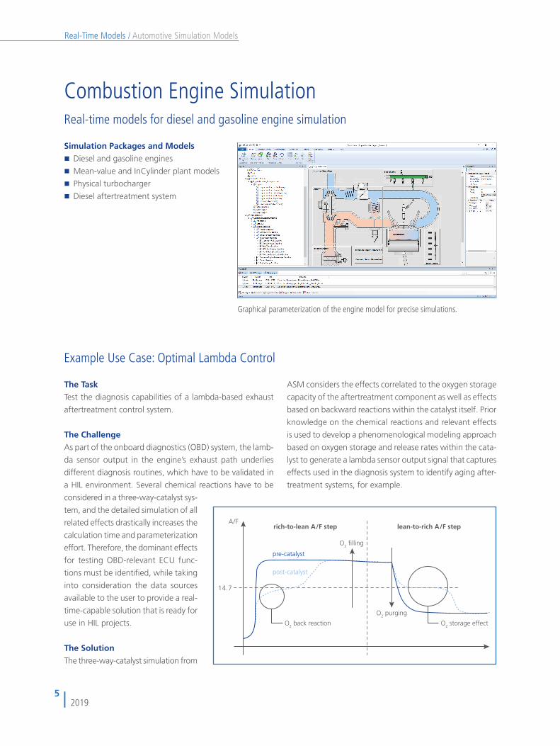
ASM TrailerTrailer model with hitch and four axles
The Trailer Model for Cars and TrucksASM Trailer is an extension to the ASM Vehicle Dynamics
Simulation Package. It is based on a multibody system
consisting of a trailer body, an arbitrary number of axles
and an optional dolly. The model also includes suspensions,
tires, brakes and aerodynamics. The connection to the tow-
ing vehicle is provided via a hitch that includes mechanical
stops. The trailer and all axles can be activated or deacti-
vated during simulation without new code generation.
Components and Characteristics
� Modular multibody system (MBS)
� Trailer body
� Arbitrary number of axles (all axles steerable)
� Dolly extension for full trailer simulation
� Multiple trailers (road train) as an option
� Tire models TMEasy and Magic Formula
� Table-based suspension
� Ball-joint hitch (including mechanical stops)
� Brakes
� Aerodynamics
� Additional loads
� Graphical parameterization in ModelDesk
The trailer can be confi gured as a semitrailer or it can have an optional dolly extension. It supports the simulation of road trains consisting of
a truck tractor and multiple trailers.

22
Automotive Simulation ModelsReal-Time Models /
2019
The trailer model can be confi gured for different trailer types,
and it can be used with various towing vehicles.
The trailer, axles, and wheels can be modifi ed during simulation, e.g.,
trailer coupled/uncoupled, axles activated/deactivated, and the wheels
can have single tires or twin tires. No code generation is required.
Axle activation/deactivationTrailer coupling/uncoupling
23
Automotive Simulation ModelsReal-Time Models /
2019
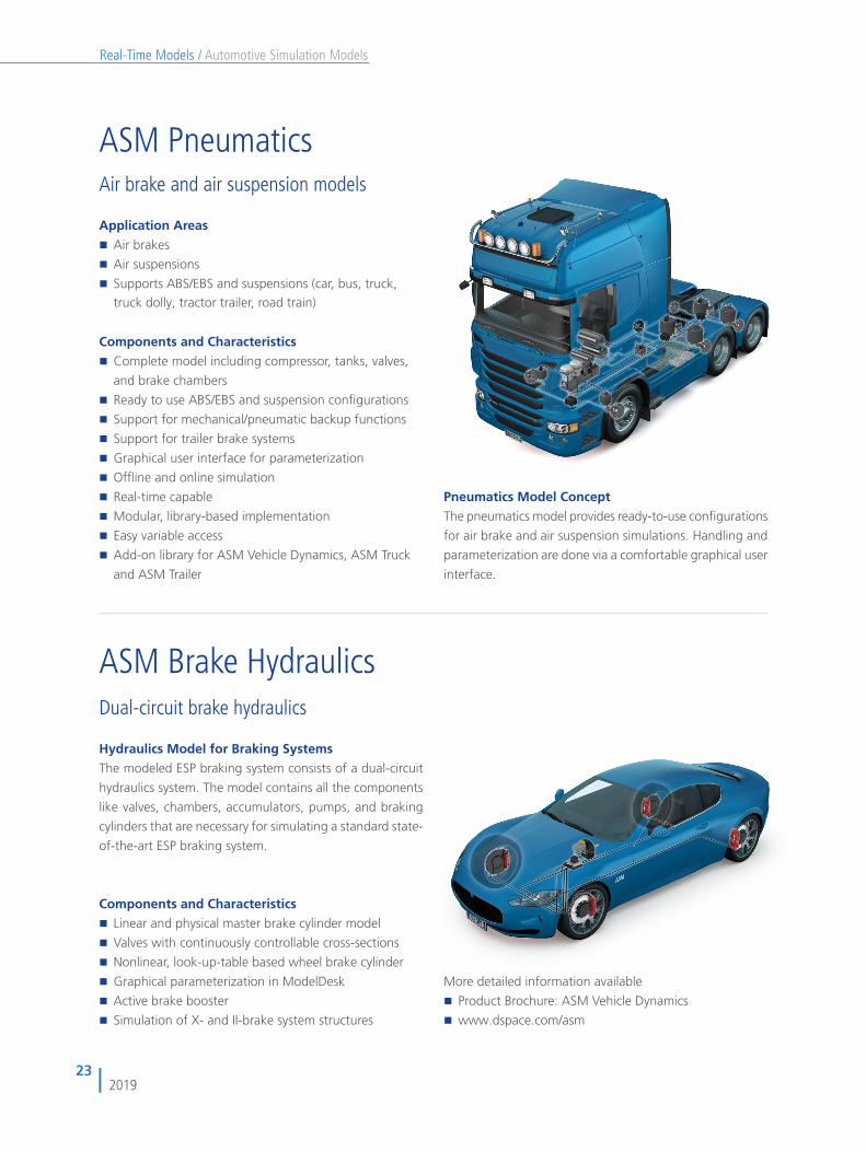
ASM Brake HydraulicsDual-circuit brake hydraulics
Components and Characteristics� Linear and physical master brake cylinder model
� Valves with continuously controllable cross-sections
� Nonlinear, look-up-table based wheel brake cylinder
� Graphical parameterization in ModelDesk
� Active brake booster
� Simulation of X- and II-brake system structures
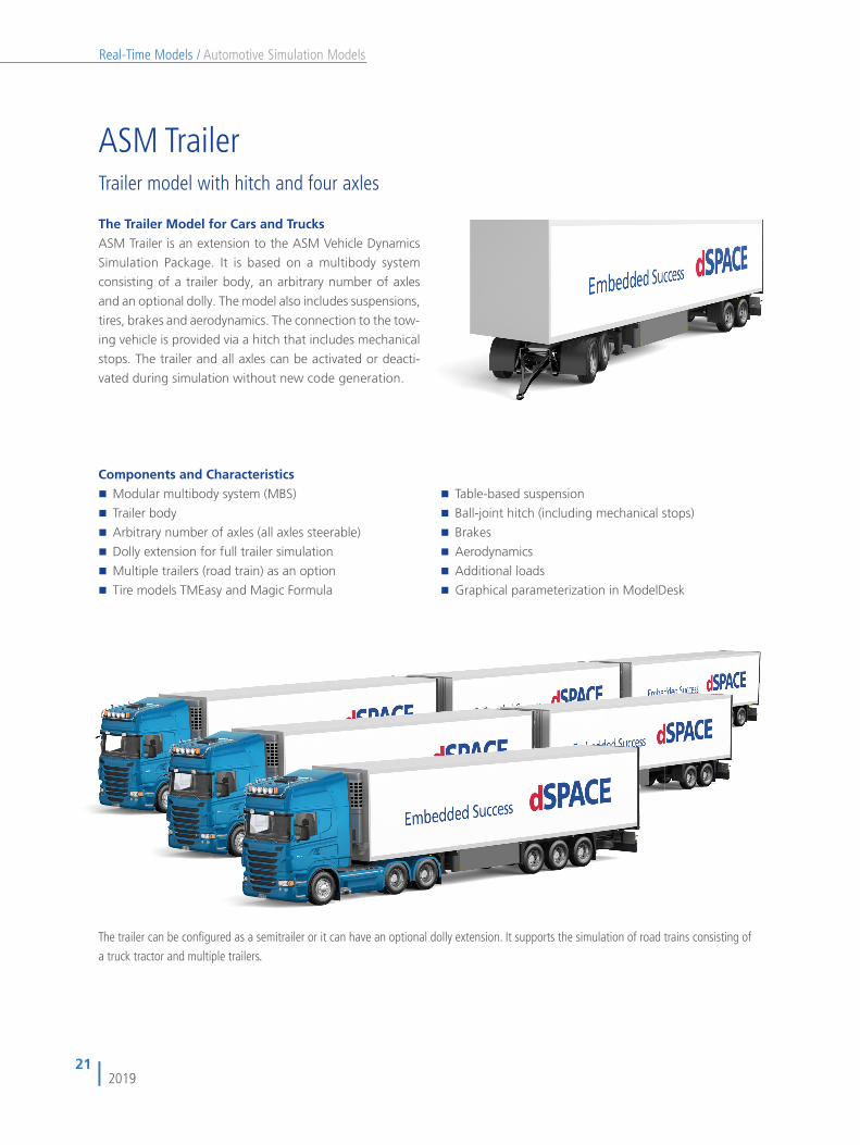
Application Areas� Air brakes
� Air suspensions
� Supports ABS/EBS and suspensions (car, bus, truck, truck dolly, tractor trailer, road train)
Components and Characteristics� Complete model including compressor, tanks, valves,
and brake chambers
� Ready to use ABS/EBS and suspension confi gurations
� Support for mechanical/pneumatic backup functions
� Support for trailer brake systems
� Graphical user interface for parameterization
� Offl ine and online simulation
� Real-time capable
� Modular, library-based implementation
� Easy variable access
� Add-on library for ASM Vehicle Dynamics, ASM Truck
and ASM Trailer
ASM PneumaticsAir brake and air suspension models
Pneumatics Model ConceptThe pneumatics model provides ready-to-use confi gurations
for air brake and air suspension simulations. Handling and
parameterization are done via a comfortable graphical user
interface.
More detailed information available
� Product Brochure: ASM Vehicle Dynamics
� www.dspace.com/asm
Hydraulics Model for Braking SystemsThe modeled ESP braking system consists of a dual-circuit
hydraulics system. The model contains all the components
like valves, chambers, accumulators, pumps, and braking
cylinders that are necessary for simulating a standard state-
of-the-art ESP braking system.
24
Automotive Simulation ModelsReal-Time Models /
2019
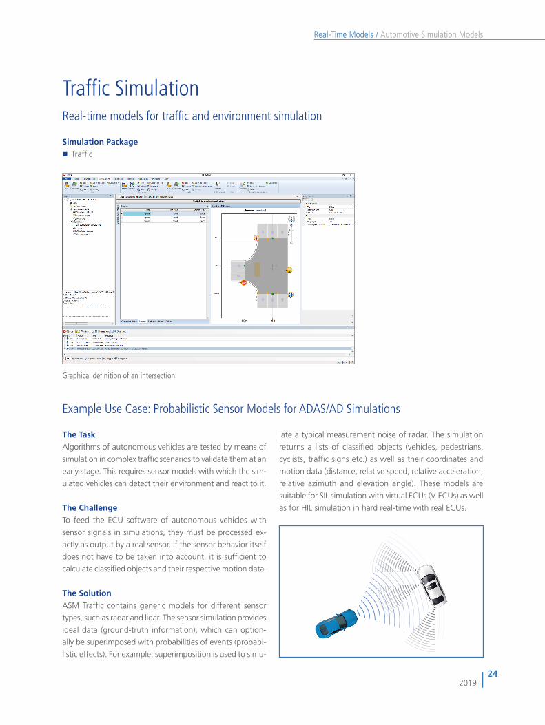
Traffi c SimulationReal-time models for traffi c and environment simulation
Simulation Package� Traffi c
Graphical defi nition of an intersection.
The Task Algorithms of autonomous vehicles are tested by means of
simulation in complex traffi c scenarios to validate them at an
early stage. This requires sensor models with which the sim-
ulated vehicles can detect their environment and react to it.
The Challenge To feed the ECU software of autonomous vehicles with
sensor signals in simulations, they must be processed ex-
actly as output by a real sensor. If the sensor behavior itself
does not have to be taken into account, it is suffi cient to
calculate classifi ed objects and their respective motion data.
The Solution ASM Traffi c contains generic models for different sensor
types, such as radar and lidar. The sensor simulation provides
ideal data (ground-truth information), which can option-
ally be superimposed with probabilities of events (probabi-
listic effects). For example, superimposition is used to simu-
Example Use Case: Probabilistic Sensor Models for ADAS/AD Simulations
late a typical measurement noise of radar. The simulation
returns a lists of classifi ed objects (vehicles, pedestrians,
cyclists, traffi c signs etc.) as well as their coordinates and
motion data (distance, relative speed, relative acceleration,
relative azimuth and elevation angle). These models are
suitable for SIL simulation with virtual ECUs (V-ECUs) as well
as for HIL simulation in hard real-time with real ECUs.

25
Automotive Simulation ModelsReal-Time Models /
2019
ASM Traffi cReal-time environment simulation with traffi c, objects, and sensors
(For information on defi ning traffi c scenarios, please see the Traffi c Editor which is part of ModelDesk, p. xxx)
Features at a glance� Simulation of complex traffi c scenarios
� Road network simulation
� Static and moving objects like traffi c signs and
vulnerable road users
� Multiple traffi c sensor types supported
� Graphical defi nition of roads, scenarios,
and environment
Application AreasASM Traffi c adds traffi c and environment simulation to
dSPACE’s Automotive Simulation Models (ASM). It supports
you in developing and testing advanced driver assistance
systems (ADAS) that react to other vehicles or objects, like
adaptive cruise control (ACC) and intersection assistants.
The model simulates a road network, the vehicle under test,
a multitude of fellow vehicles and the necessary environment.
The test vehicle can be equipped with multiple sensors for
object detection and recognition (ego-vehicle). ASM Traffi c
is typically used for hardware-in-the-loop testing of elec-
tronic control units (ECUs) or for early function validation
by offl ine simulation during the design phase of controller
algorithms.
Key Benefi tsASM Traffi c is so fl exible that any kind of traffi c scenario
can be created to ensure thorough testing of ADAS control-
lers. It supports the creation of complex road networks, and
you can defi ne sophisticated traffi c scenarios on the roads.
The simulated environment can consist of static and movable
objects, like traffi c signs and pedestrians. Various sensor
models and user-defi nable sensors are available to detect
these objects. To test pre-crash functionalities, you can
defi ne traffi c scenarios that in real life could result in an
accident, and observe system behavior under challenging
conditions. Traffi c scenarios can be modifi ed and immedi-
ately simulated without having to generate code again.
Components and CharacteristicsASM Traffi c consists of a graphical user interface (GUI) and
a set of simulation models that perform in real time. The
GUI provides several interfaces to defi ne the necessary
components like road networks, traffi c signs, traffi c vehicles,
and sensors. Trajectories for all vehicles, objects and pedes-
trians are calculated in real time according to the defi ned
traffi c scenarios. ASM Traffi c supports specifi c scenarios such
as oncoming traffi c, stop and go, and pedestrians. The
Scenario Editor is the user interface for very fl exible and easy
traffi c scenario defi nition.

26
Automotive Simulation ModelsReal-Time Models /
2019
Road Networks
Features� Road networks with roads and intersections for vehicle
dynamics and ADAS use cases
� Segment- and coordinate-based road defi nition
� Lanes with smooth transitions and specifi c line
defi nitions
� Up to 5 lanes per lane segment
� Support for lane detection sensors
� GPS coordinate exchange with turn-by-turn navigation
development tools
� Simulation of tire characteristics and road surface
conditions like split-μ surfaces, bumps, potholes
� Simulation of lines according to EU regulation
351/2012 and support of free lines and barriers for
construction area simulation.
� Import and Export of OpenDRIVE-format
Defi ne roads and junctions graphically.
Scenario EGO-Vehicle
Features� Movement control of vehicle under test (ego-vehicle)
� Scenario segments defi ned by distance or time
� Event-based segment changes
� Lane driving and lane transition/change defi nitions
� Trigger events for specifi c scenario activities
� Open- and closed-loop scenarios
� Velocity, steering, and pedal actuation can be set by
using measurement data
� User output signals programmable via time and
distance
� External velocity and pedal access for man-in-the-loop
use cases
Defi ne where and how the ego-vehicle drives on the road network.

27
Automotive Simulation ModelsReal-Time Models /
2019
Scenario Fellow Vehicles
Features� Simulation of objects around ego-vehicle
� Defi nition of various traffi c situations and complex
scenarios
� Lane driving and lane change defi nition
� Support for intersections with oncoming and crossing
traffi c
� Scenarios based on distance, velocity and acceleration
� Independent and interdependent movements
� Time- and road-based trigger events
� Direct link between model and animation update
� Unlimited number of moving objects possible Defi ne where and how the surrounding fellow vehicles drive on the road network.
Objects and Sensors
Features� Defi nition of any number of traffi c objects
� Road- and intersection-based positioning
� Graphical representation in MotionDesk
� Moving objects like pedestrians
� Static objects like variable traffi c signs, traffi c lights,
parked vehicles, houses
� 2-D object sensor
� 3-D object sensor
� 3D-sensor with realistic cone scope and
timing behaviour
� Line sensor
� Custom sensor
� Variable traffi c sign and traffi c light sensor
Defi ne sensors on the vehicle and traffi c signs, obstacles and scenery along the road.
Overview of Objects and Sensors
Sensor Type Object Sensor Output
Traffi c SignsSpeed limit, 80
2-D
Custom
Adult / Child
3-D
80
More detailed
information available:
� Product Brochure:
ASM Traffi c
� www.dspace.com/asm

28
Automotive Simulation ModelsReal-Time Models /
2019
ModelDeskThe graphical user interface
ModelDesk ConceptModelDesk is a graphical user interface for simulation,
intuitive model parameterization and parameter set man-
agement. It also provides project handling and allows
parameter sets to be downloaded to offl ine and online
simulations. It supports tool automation via Python scripts.
ModelDesk can be used seamlessly from parameterization
to offl ine and online simulation, and fi nally to parameter
and result management.
Graphical ParameterizationThe model components and their subsystems are repre-
sented by a hierarchical graphical structure. The model
components to be parameterized can be selected from the
top level. Users have the vehicle model before them and
can browse through its systems, guided by graphical repre-
sentations of the modeled components.
Parameter ManagementModelDesk’s Project Navigator provides a means of organiz-
ing and managing large-scale model parameterization
projects. Parameter fi les can be created and assigned to
each model component (differential, tires, road, etc.), and
complete vehicle parameter sets can be created and man-
aged. Existing parameter fi les can be selected from a
parameter pool and applied by drag & drop.
Main Features
� Offl ine and online simulations
� Graphical user interface
� Parameter set management
� Road Generator
� NEW: Integrated test functionality
� Scenario Editor
� Tool automation
� Preprocessing for engine models
� Custom model parameterization
Benefi ts� Seamless simulation process from MIL to HIL
� Intuitive, graphically supported parameterization
� Parameters changed online and offl ine
� Managing parameter sets and entire projects
ModelDesk’s user interface for selecting model subsystems for confi guration, parameterization, and simulation on platforms like MATLAB/Simulink, dSPACE VEOS, and dSPACE Simulator.

29
Automotive Simulation ModelsReal-Time Models /
2019
Simulation ManagementModelDesk includes powerful functions for directly executing
and displaying simulations, and managing their results:
� Starting and stopping a simulation
� Maneuver control: starting and stopping predefi ned
maneuvers and traffi c scenarios.
� Plotters for visualization
� Saving, comparing and managing simulation and
measurement data
� Saving simulation experiments
(driving maneuvers, roads, traffi c scenarios, etc.)
� Direct demo model access
Features� Plots of ASM signal buses
� Plots of user-defi ned signals
� Plotter confi gurations can be saved
� The same confi guration to be used online and offl ine
� Plot printouts
� Confi guration comprises measurements, simulation
and parameters
PlotterModelDesk features an integrated plotter which displays
signals from the ASMSignalBus. The signals have the same
structure as in the Simulink model. The bus can include
user-defi ned signals. Plotter confi gurations can be defi ned
and stored, and the same single confi guration can be used
seamlessly online (HIL simulations) and offl ine (Simulink
simulations). A confi guration includes the following data:
simulation results, measurements, and parameter sets con-
sisting of vehicle parameters, roads, maneuvers, and/or
traffi c. A confi guration collects together all the sources and
conditions that the plotted results are based on.
Select from various demo modelsto jump start new projects.
ModelDesk’s plotter displaying various vehicle dynamics signals.
Visualization with MotionDeskModelDesk and MotionDesk work seamlessly together. In
ModelDesk, users can defi ne scene types such as country
roads, tree-lined roads, and urban areas. The scenes are
then automatically generated in MotionDesk with appropri-
ate objects like buildings, trees, borders, refl ector posts, and
street lamps. These can also be modifi ed as required in
MotionDesk’s integrated Scene Editor.

30
Automotive Simulation ModelsReal-Time Models /
2019
Road GeneratorThe Road Generator is the graphical user interface for defin-
ing road networks and sophisticated road features. Roads
can be assembled from geometric segments or imported.
Features such as lanes, intersections, height, inclination,
surface condition, etc., can easily be added to a road by
editing attributes that are displayed in 1-D diagrams. The
whole road network is visualized in a 2-D view. The road
design also interacts closely with the 3-D animation software
MotionDesk to define the environment. The Road Generator
gives ideal support to complex traffic scenario creation in
the development and testing of advanced driver assistance
systems (ADAS).
The Road Generator supports the definition of intersections and complex road networks. The user interface provides a list of road segments (upper left), an overview of the whole road network (middle), and a view of lane details (right).
Features
� Support for vehicle dynamics and advanced driver
assistance traffic scenarios
� Segment and coordinate-based road definition
� Intersections and junctions
� Lane, line and traffic sign definition
� Height, inclination, and surface condition applied via
segment-independent road coordinates
� Easy definition of bumps, profiles, split-μ areas, etc.
� Dedicated 1-D and 2-D views of road features
� OpenDRIVE® format export
� Road import: map data (like OpenStreetMap, etc.),
ADAS RP (Nokia HERE), and OpenDRIVE® format
� Road networks and predefined sceneries are automa-
tically imported into MotionDesk (city center, country
road, highways)
� Definition of driving routes
� Definition of lane-independent lines and shapes for
concrete barriers or repeating objects
� Unlimited number of lanes
� NEW: Support for non-drivable lanes (e.g. bicycle lanes,
emergency lanes)
Road Networks

31
Automotive Simulation ModelsReal-Time Models /
2019
Scenarios
Scenario EditorThe Scenario Editor is used to define where and how dy-
namic objects, such as vehicles, pedestrians, etc. move on
the road network. These types of scenarios include an EGO
vehicle and optionally an unlimited number of fellow ve-
hicles. Scenarios can be created for vehicle dynamics simu-
lation and traffic simulation or a combination of both.
Scenarios can be as simple as following a predefined road
profile with route definitions or they can be complex traffic
situations with a large number of vehicles, pedestrians, etc.
on complex road networks. With its UML-like approach, the
Scenario Editor lets you create sophisticated diagrams with
good clarity. Therefore, it is the ideal tool for defining test
scenarios for automated driving.
Features
�� Definition of driving and traffic scenarios on road
networks
�� Scenario segment definition by distance or time
�� Lane driving and lane change definitions
�� Easy-to-use fellow vehicle activity definitions
�� Definition of steering and pedal stimuli or driver-based
maneuvers
�� Standard maneuvers included (NCAPs, lane change,
μ-split, steady-state cornering, fish hook, etc.)
�� Lateral and longitudinal stimuli can be imported from
measured data (MAT files).
�� Programmable user output signals using time or
distance
�� Overview and detailed views
Example of the scenario definition page.
32
Automotive Simulation ModelsReal-Time Models /
2019
NEW: Testing
Integrated Test AutomationModelDesk now provides an integrated ASM-based test
functionality called Testing. It lets users defi ne, manage and
execute automated test procedures directly in ModelDesk.
These procedures contain one or more simulations, which
can be performed with parameter variations. This way,
vehicle dynamics maneuvers, powertrain and electrical sys-
tem tests as well as traffi c simulations can be easily and
intuitively automated and validated. In addition to the clas-
sic test automation tasks, there are other fi elds of applica-
tion, such as direct model validation by comparing simula-
tions and measurements or quick plausibility tests of com-
plex scenarios for autonomous driving. Test procedures with
ModelDesk and ASM can be executed throughout the entire
development process on the dSPACE simulation platforms.
Moreover, it is possible to integrate ASM-based tests in an
overall test automation setup based on AutomationDesk
and SYNECT.
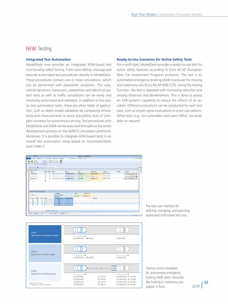
Ready-to-Use Scenarios for Active Safety TestsFor a swift start, ModelDesk provides a ready-to-use test for
active safety features according to Euro NCAP (European
New Car Assessment Program) protocols. The test is an
automated emergency braking (AEB) maneuver for moving
and stationary cars (Euro NCAP AEB CCR). Using the testing
function, the test is repeated with increasing velocities and
varying distances and decelerations. This is done to assess
an AEB system’s capability to reduce the effects of an ac-
cident. Different evaluations can be conducted for each test
case, such as simple signal evaluations or score calculations.
Other tests, e.g., for vulnerable road users (VRUs), are avail-
able on request.
The new user interface for defi ning, managing, and executing automated ASM-based test runs.
CCRs*:Approach to stationary target
CCRm*:Approach to slower target
CCRb*:Approach to braking target
v0=30 km/h ... 80 km/h
v0=30 km/h ... 80 km/h
v=0 km/h
v=20 km/h
v0=50 km/hv0=50 km/hv0=50 km/hv0=50 km/h
d0=12 md0=40 md0=12 md0=40 m
v0=50 km/h, a=-2 m/s2
v0=50 km/h, a=-2 m/s2
v0=50 km/h, a=-6 m/s2
v0=50 km/h, a=-6 m/s2* CCR: Car-To-Car Rear; s: standing; m: moving; b: braking
d0 Testing control strategies for autonomous emergency braking (AEB) when obstacles like braking or stationary cars appear in front.

33
Automotive Simulation ModelsReal-Time Models /
2019
MATLAB programming environment. In addition to this
customizable parameter calculation, sophisticated error
handling procedures have been integrated to support the
users during parameterization.
Processing
Parameter ProcessingModelDesk provides a fully integrated parameterization
workfl ow. Users can include initial data, such as measure-
ments, functions, and settings, fl exibly and process it into
parameters optimized for simulation models. Users can write
the processing routines for parameters in the well-known
Features
� Read and process measurement data
� Function administration
� Settings administration
� Execute functions with appropriate error handling
� Adapt parameter as a result of a processing function
Use Cases� Engine parameterization based on testbench
measurement
� Battery parameterization based on impedance
spectroscopy
� Suspension kinematic parameterization based on
kinematic and compliance testbench data
Custom Models and Demo ProjectsThis feature can also be used in combination with custom
components to parameterize own libraries with ModelDesk.
A demo projects for the ASM engine models provide pre-
defi ned parameterization routines, to deliver a semi-auto-
mated calculation of all model parameters.
The processing feature transfers measurements, settings, and functions into parameters optimized for simulation.
ModelDesk
Import
Download
Measurement data
Process
dSPACE SCALEXIO(real-time simulation)
MATLAB®/Simulink®
(offline simulation)dSPACE VEOS
(offline simulation)
Parameter
34
Automotive Simulation ModelsReal-Time Models /
2019
Tool Automation
Remote Control and Batch Processing for ModelDeskTo perform long-term tests or parameter studies, ModelDesk
provides script-based tool automation. This gives you max-
imum fl exibility to defi ne custom simulation scenarios. Tool
automation can be performed by means of scripting lan-
guages like Python and MATLAB M scripts.
The scripts can be executed either externally to remote-
control ModelDesk or internally when ModelDesk’s batch
mode is used. The batch mode functionality is realized by
a Python interpreter that supports Python 2.5.1.
Benefi ts
� Direct alteration of traffi c scenarios
� Simulation-based parameter studies
� Automated marginal condition analyses/detection
� Long-term behavior studies
� Sequential scenario executions
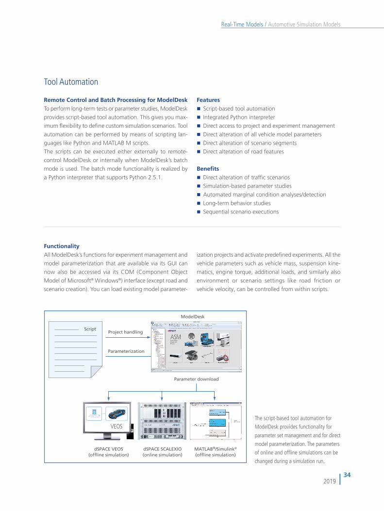
FunctionalityAll ModelDesk’s functions for experiment management and
model parameterization that are available via its GUI can
now also be accessed via its COM (Component Object
Model of Microsoft® Windows®) interface (except road and
scenario creation). You can load existing model parameter-
ization projects and activate predefi ned experiments. All the
vehicle parameters such as vehicle mass, suspension kine-
matics, engine torque, additional loads, and similarly also
environment or scenario settings like road friction or
vehicle velocity, can be controlled from within scripts.
Project handlingScript
Parameterization
ModelDesk
dSPACE SCALEXIO(online simulation)
MATLAB®/Simulink®
(offline simulation)dSPACE VEOS
(offline simulation)
Parameter download
Features� Script-based tool automation
� Integrated Python interpreter
� Direct access to project and experiment management
� Direct alteration of all vehicle model parameters
� Direct alteration of scenario segments
� Direct alteration of road features
The script-based tool automation for
ModelDesk provides functionality for
parameter set management and for direct
model parameterization. The parameters
of online and offl ine simulations can be
changed during a simulation run.

35
Automotive Simulation ModelsReal-Time Models /
2019
Custom Model Parameterization
Graphical Parameterization of Custom ModelsModelDesk supports the graphical parameterization of
model parts that were replaced by custom models or custom
extensions to ASMs. This allows you to manage all the
parameters of a project from a single source.
Features
�� Automatic generation of new parameter pages based
on custom models
�� Controls provided according to parameter dimension
(scalar, vector, table)
�� Original ASM and customized model parts displayed as
one system
Benefits�� Centralized parameter management
�� Graphical parameterization without detailed modeling
knowledge
Model PreparationFor use in ASM, custom model libraries have to be prepared
according to ASM guidelines in order to parameterize them
in ModelDesk. The guidelines mainly define how parameters
are declared with masked variables and a fixed declaration
structure. Libraries can have multiple masked subsystems,
and each subsystem has its own parameter page for sepa-
rate parameterization.
Custom Library RegistrationModelDesk’s registration function lets you select new librar-
ies to parse them and make their parameters available
graphically. During registration one or more parameter
pages are created automatically, depending on the number
of masked sub systems. Each page lists the controls of de-
clared parameters. Controls can be single entry fields for
scalar types, multiple entry fields for vectors, or complex
tables for table-based parameters.
Navigating Custom ParametersWhenever a model containing blocks from a registered
custom library is loaded into a ModelDesk experiment the
related parameter pages of these blocks are provided. They
can be selected in the Navigator. Each library is represented
as a branch in the hierarchy with links to the subsystem
pages. The new pages can be used in exactly the same
manner as the standard pages.
Custom parameter page created by ModelDesk. Controls for scalar,
vector or table parameters are automatically labeled with the unit
and caption as defined in the custom library.

36
Automotive Simulation ModelsReal-Time Models /
2019
ASM Versions and License Concept The ASM License ConceptThe ASM models come with different license types: Devel-
oper License, Runtime License. This lets users apply the
models in various kinds of applications, without losing any
of the characteristic ASM flexibility.
�� Exchangeability – You can use both licenses on one
PC or split them to have one PC for model maintenance
and one PC for simulation platform operation.
�� Mutual Parameterization – Both license types let you
parameterize all models with ModelDesk’s parameteri-
zation options for simulation on a PC (offline) or on
dSPACE real-time hardware (online).
�� Seamless 3-D Animation – The vehicle dynamics
models provide access to MotionDesk with all license
types. The model must include the MotionDesk block-
set.
ASM Developer LicenseThe Developer License is designed specifically for modifying,
parameterizing and preparing the open Simulink models
for simulation on a real-time platform. The license lets you
generate real-time code. Moreover, the license can be used
for Simulink simulation on a PC (offline).
Properties
�� Modular developer models viewable down to the
Simulink block level
�� Modular, encapsulated operator models, designed
specifically for Simulink simulation (offline)
�� Easy substitution or extension of ASM models by
customer-specific model parts
�� Support for real-time and VEOS code generation
ASM Runtime LicenseThe Runtime License is designed specifically for simulation
on a real-time platfor (online) and Simulink simulation of
operator models (offline).
Properties�� Code execution on dSPACE real-time hardware
(dSPACE Simulator, SCALEXIO)
�� Code execution on dSPACE VEOS
�� Code already generated from the models via the
Developer License
�� Simulink simulation of operator models, which are
modular, encapsulated, and designed specifically for
Simulink simulation (offline). Not included with ASM
Engine InCylinder models.
The Benefits�� A simulation environment that seamlessly covers
the offline and online (real-time) worlds.
�� ModelDesk is the parameterization tool throughout the
entire process, which means that the parame terizations
can be reused.
�� Cost-efficient license types for offline and online (real-
time) simulation
�� Simulation models parameterized and reconfigured
in ModelDesk with the Runtime License. This enables
real-time simulation on a dSPACE platform without an
additional MATLAB license.