Embed Size (px)
Citation preview

20th International Conference on Adaptive Structures and Technologies
October 20-22, 2009, Hong Kong
Automotive Research Advances in Smart Materials and Devices at the GM/UM SMS Collaborative Research Laboratory
Jonathan Luntz1, Diann Brei1*, Poorna Mane1, John Redmond1, Brian Barnes1, John Shaw2 ,
Nancy L. Johnson3, Alan L. Browne3, Paul W. Alexander3, Nilesh Mankame3 1 Mechanical Engineering Dept., University of Michigan, Ann Arbor, MI 48109-2125 USA
2 Aerospace Engineering Dept., University of Michigan, Ann Arbor, MI 48109-2125 USA
3 General Motors R&D, Warren, MI 48090-9055 USA
ABSTRACT
The field of smart materials and structures has evolved in the last 10 years to the point of viability
for commercial mass-production industries. A good example of this is the automotive industry where
there has been a 600% increase in patent applications. While the fundamental science is present for
many smart materials such as shape memory alloys or piezoelectrics, there have been only a few
instances of successful commercialization due to lack of technology and industrial infrastructure. To
make a clear path to hasten the transition from all the progress made during the past decades of
research into launched competitive products, General Motors (GM) has teamed with the College of
Engineering at the University of Michigan (UM) to establish a $2.9 Million Collaborative Research
Laboratory (CRL) in the area of Smart Materials and Structures. The mission of the SMS CRL is to
exploit the emerging capabilities of smart materials and structures to create and support innovative
advanced device technologies for application within the automotive industry. The SMS CRL is
structured into three thrust areas: Smart Device Technology Innovation, Smart Materials Maturity,
and Mechamatronic System Design Methodology. This paper presents a brief overview of the
mission, global infrastructure and collaborative philosophy of the GM/UM SMS CRL and its recent
advancements including: devices for pedestrian protection, Shape Memory Alloy (SMA)
technologies such as ultrafast latches and linear ratchet drives, SMA material modeling,
characterization, and shakedown studies, and model-based design tools for SMA wires. The most
important accomplishment has been the new research and development paradigm that has at the core
a truly collaborative, cross–talk relationship between all the multi-level thrust areas and the SMS
CRL team composed of researchers, students, and engineers across the world resulting in synergism
between projects to accelerate the time between theory and concept to fruitful applicable results.
Keywords: smart materials, active materials, shape memory alloys, mechamatronics
* Corresponding author: University of Michigan, Mechanical Engineering, 2350 Hayward St., 2250 G.G. Brown, Ann
Arbor, MI 48109-2125,Tel: (734) 763 6617; Fax: (734) 647 3170; E-mail: [email protected]

Page 2
1 INTRODUCTION
For several decades, the military, industrial, and medical sectors have invested in smart
materials-based actuation to enable elegant, energy dense actuation solutions for a variety of devices
[1]. This effort has provided an enhanced understanding of a suite of active materials, and provided a
rudimentary foundation for the analysis of smart materials devices. Yet until recently, only a handful
of niche smart materials-based products have successfully transitioned to market. Examples include
piezoelectric actuators in compact audio speakers, accelerometers and micro-positioning systems
[2,3], magnetorheological shock absorbers or struts for use in vehicle suspension systems [4], shape
memory polymer repair material for auto repair applications, and SMA arterial stents, valves, and
couplings [5]. Smart material actuators often exceed the energy and power densities of conventional
actuators by orders of magnitude, are simplistic in architecture relative to typically complex
assemblies found in conventional actuation, and create opportunities for compact, economical
actuation. These can lead to true benefits for industry as evidenced by over 600% growth in smart
material patents in the last decade alone [6].
One good example of this growth is the automotive industry with important applications such as
adaptive aerodynamics for increased fuel economy, pedestrian protection and enhanced energy
dissipation for crash safety, active suspensions, and controllable closures [7-10]. Despite the
potential of smart materials to transform the automotive industry, it has been difficult to transition the
technology to market due to material complexities and a lack of design tools to support engineers.
For example, shape memory alloy (SMA) is highly desirable for automotive applications due to its
robustness, high energy density, and ability to manufacture high yields at low cost. For many years,
several technical barriers have stood in the way of its widespread use such as low frequency,
difficulty to accurately predict performance under varying conditions, performance degradation over
time, and the need to package long or many wires within compact form factors. The complex
behavior of the material requires a fairly detailed level of material knowledge to design devices.
Unfortunately, general methodologies or design tools to aid inexperienced engineers are rare. In
addition, while SMA allows many options in terms of device architecture to provide tailored
performance and packaging of devices, there currently does not exist a “critical mass” of device
architectures with corresponding performance models to support the model-based design of SMA
devices; thus, designers are typically forced to start from scratch. This is compounded by the fact that
the workforce is unfamiliar with SMA and how to engineer with it. Thus, in addition to inventing
new technologies, the foundational science, design tools, and education regarding smart material
actuation (and all its nuances) are crucial in enabling the incoming workforce to be savvy smart
materials engineers. All of these issues are common across smart materials, and are not unique to
SMA.
To speed the transition from the past decades of research into launched competitive products,
General Motors (GM) has teamed with the College of Engineering at the University of Michigan
(UM) to establish a $2.9 million Collaborative Research Laboratory (CRL) in the area of Smart
Materials and Structures. The mission of the SMS CRL is to develop the knowledge base to exploit
the emerging capabilities of smart materials and structures to create and support innovative advanced
device technologies for application within the automotive industry. This paper presents a brief
overview of the mission, global infrastructure of the GM/UM SMS Collaborative Research
Laboratory along with a set of examples highlighting the synergistic nature of the work within the
SMS CRL with cross-talk between all areas. The example projects center around a particular device:
the SMART (SMA ReseTable) hood lift for pedestrian protection, from which a wide variety of
projects have spawned. Two main SMA technologies are presented, SMA driven ratcheting and
ultrafast latches, along with fundamental research in SMA material modeling, characterization, and
shakedown behavior that enabled the model-based design of these core technologies. General
packaging methods are also described such as spooled SMA wire actuators and SMA cables without

Page 3
which many of the technological developments would not be practical. A general approach to
creating design tools is also discussed which enable general engineers, without experience in smart
materials, to develop smart materials based devices and to take advantage of advancements in smart
materials. Stressed in the paper is the collaborative, synergistic research paradigm adopted by the
SMS CRL which empowers this team composed of researchers, students, and engineers across the
world to advance the field of smart materials and efficiently and effectively bring theoretical
developments to marketable application inside and outside the automotive industry.
2 GM/UM SMS CRL STRUCTURE
The overriding goal of the GM/UM SMS CRL is to exploit the emerging capabilities of smart
materials and structures to create and support innovative advanced device technologies for
automotive applications of value and interest to GM and extension to dual technologies for strategic
partners. To this effect the SMS CRL has a constantly evolving mission as new technologies emerge
and the knowledge base grows. To achieve this mission the SMS CRL has identified key thrust areas
which identify research issues and develop tools and design methodologies to integrate smart
materials into mature automotive applications.
2.1 Mission
The SMA CRL was started in 2006 with the overall goal of exploiting smart materials based
research to propel transformative device technologies into the marketplace towards the reinvention of
the automobile. There are many facets to this mission including:
Invention: Utilize emerging smart materials to invent embryonic leap-frog device
technologies with potential to transform the marketplace.
Science: Conduct theoretical and experimental research to expand the knowledge base of
smart materials to facilitate the development of new technologies for automotive
applications.
Tools: Develop design methodologies and tools to support smart material technologies,
quicken the development cycle and successfully progress them to marketable automotive
products.
Application: Foster a collaborative and synergistic environment between researchers and
engineers at GM, UM and their strategic partners, bringing together a breadth and depth of
expertise to improve the progression from basic materials research to innovative
technology development and ultimately its inclusion in successful, marketable products.
Education: Provide research opportunities for graduate students and enhance GM‟s
ability to attract exceptional engineering talent with training in areas of interest to GM.
2.2 Research Thrust Areas
To achieve this mission the SMS CRL is focused initially on three thrust areas: 1) Smart Device
Technology Innovation, 2) Smart Material Maturity, and 3) Mechamatronic System Design

Page 4
Methodology. It should be noted that these thrust areas, their projects, and this organizational
structure as a whole are expected to evolve over time in response to changing needs and the SMS
CRL structure allows this adaptability.
The primary focus of the Smart Device Technology Innovation thrust area is to invent new smart
material based device technologies that push the frontier of capabilities. While it is foreseen that most
of these technologies will be initiated by specific automotive applications, the SMS CRL seeks to
develop a robust technology base rather than a “gadget”. It is expected that by utilizing smart
materials, substantial advances can be made leading to disruptive, leap–frog type technologies versus
incremental steps beyond conventional technologies within the market place. By developing new
technologies versus specific artifacts/devices, these technologies will have broad application across
many vehicle components/systems and relevance to many other industries such as appliance, oil,
military, aerospace and medical.
It is fully expected that during the course of the technology development, that many basic
research issues will be faced. Thus, the objective of the second thrust area, Smart Material Maturity,
is to carry out theoretical and experimental research to expand the knowledge of smart materials with
regards to fundamental issues affecting implementation such as material uniformity and reliability
and the effect of environmental factors and use history on performance and use life. Such issues are
currently viewed as unknown frontiers impacting the commercial viability of smart materials. The
intent is not to develop new materials but instead usher existing materials to a level of maturity which
allows for successful integration into products.
The third thrust area is Mechamatronic System Design Methodology where mecha- stands for
mechanical, ma- stands for smart materials and –tronic stands for electronics [11]. The objective of
this thrust area is to build a better understanding of the design process suited for these systems
enabling the creation of synthesis and analysis methods/tools to quicken the design cycle and enable
engineers both familiar and unfamiliar with smart materials to quickly and with confidence develop
robust systems based upon the new technology foundations established in the SMS CRL.
2.3 Infrastructure
A key feature of the SMS CRL is its cooperative and collaborative infrastructure. First, the
leadership roles within the SMS CRL are cooperative. Each thrust area and the projects within each
thrust area has leaders from both GM and UM and the entire SMS CRL is jointly directed by a
director from UM and a director from GM. The project co-leaders are responsible for the execution of
the project and any identified deliverables. The Laboratory co-directors, under the recommendations
from the Thrust Area Leaders, have the responsibility for coordinating research and selecting
personnel to work in these areas of technical focus. The co-directors also review and approve all new
project requests and business plans consistent with the technical thrusts of the Lab with the assistance
of an external Laboratory Review Committee.
Second, cross-functional and cross-organizational communication is expected. All the leaders are
expected to be proactive members throughout the process with expanded roles and strong
communication between all – at least on a weekly basis and in many cases on a daily basis. Nothing is
“thrown over the wall”. In addition, the entire SMS CRL meets informally bi-monthly for seminars,
tutorials, logistic meetings, etc. Finally, there are quarterly formal reviews with the SMS CRL team
along with the external General Motors Institute Review Committee to assess the progress and
guide/redirect efforts where needed. This aids in the identification of the core needs and real basic
issues that are at the heart of both institutional missions and which can be addressed through a
coupled approach.
Third, research projects, and hence students‟ theses/dissertations, span multiple thrust areas. A

Page 5
typical research project is expected to lead to a new (perhaps patentable) technological development
from the Smart Device Technology Innovation Thrust that leverages basic research findings from the
Smart Material Maturity Thrust, and the student follows through to establish the design knowledge
base and methodology for the Mechamatronic System Design Methodology Thrust so that engineers
in industry can utilize the student‟s contribution for real applications. Students are co-advised by
different faculty within the three thrust areas during different phases of their research and work
closely with various researchers/engineers at GM as the project advances. In addition to aiding in
cross-communication between thrust areas, this method is effective in training a broader,
well-rounded researcher in basic, fundamental research methods who is also, through this experience,
aware of the pragmatic issues faced in industry so that she/he can have a true impact on society. This
is critical to help form the necessary industrial workforce to support the field, and several UM
engineering graduates have already moved on to careers at GM. Thus, programs like these help to
train future leaders in industry.
Since its inception in May 2006, the SMS CRL has expanded to include many other strategic
partners beyond the initial researchers at University of Michigan (from the Mechanical and
Aerospace Engineering Departments) and General Motors Research and Development (GM R&D) in
Warren Michigan. It includes participation from other GM divisions and affiliated organizations with
which GM R&D already had pre-existing long term collaborations in the area of smart materials,
these including GM Engineering, Opel, India Science Lab, and HRL Laboratories. It is a true global
effort. While the primary focus is to develop technology for the automotive industry, many of the
technologies along with the supporting basic research and design methods are applicable across
multiple industries.
3 SYNERGISTIC RESEARCH ACTIVITY
The success of the SMS CRL is due, in large part, to its synergistic paradigm in which each
project draws upon and provides motivation for other projects, blending the lines between projects
and between thrust areas. Each project spans the spectrum from basic science to applied research to
technology development, producing more complete, more relevant results. To illustrate this, this
paper provides a tour of recent advancements within the SMS CRL via a unifying project: the
SMART Lift Device for Pedestrian protection. Pedestrian protection is a major focus of automotive
crashworthiness with new regulations taking effect worldwide [9,10]. While there are many
approaches to reducing the head-injury-criteria (HIC), a leading approach is to actively lift the hood
to increase the crush distance to rigid underhood components [12-15]. One of the key technological
challenges is the very tight timing window (between 25 and 30 ms) given the large displacements
(over 120 mm) and forces (over 1400 N) - too fast a lift may damage the hood under its own inertia
and too slow a lift will not create sufficient clearance in time to reduce HIC. Most current lift devices
are single-use, requiring the hood to be manually returned to a drivable position, and could possibly
damage the hood during lift due, as indicated, to too rapid lift rates which damage would necessitate
hood replacement. The SMART (SMA ReseTable) Lift Device (Figure 1), developed within the
Smart Device Technology Innovation thrust area, solves these problems by storing energy in a spring
and very quickly releasing it (within 4 ms) to lift the hood upon detection of an impact with a
pedestrian [9,10]. The device provides enhanced functionality over other alternatives in that the hood
can be automatically lowered to a drivable position immediately following deployment, and that the
deployment energy can be restored in the device for repeated deployment without need for user
intervention. Automatic lower and reset are critical in the case of false deployments that might result
in the case of conservative sensing strategies, an example being collisions with non-pedestrian
objects such as trash cans. For this device to be successful, a broad range of synergistic research
Page 6
activity was necessary ranging from technological developments such as high force and stroke SMA
ratchets and ultrafast latches, to basic materials research to model and characterize the SMA material
and understand its shakedown behavior over cycles, to design methodology to explore tradeoffs
between packaging and performance in terms of force and stroke, and develop methodologies and
tools for streamlining the design process. While these synergistic activities are described in this paper
in the context of the SMART Lift as an example, all the activity within the SMS CRL has this highly
collaborative and synergistic nature with a three-way supporting relationship between each of the
thrust areas, and a great deal of cross-talk between all projects. Nurturing this synergy is a strong
priority within the SMS CRL and a key to the depth and breadth developed throughout all the projects
and thrust areas.
3.1 TOoThed Linear RAtchet Drive: TOTLRAD (Smart Device Technology Innovation
Thrust)
Unique to the SMART Lift approach for pedestrian protection was the reset actuation. This
required a non-backdriveable actuator capable of safely compressing the spring used to lift the hood,
producing very large forces (over 1400 N) and large strokes (over 120 mm) while compactly
packaging inside the spring itself. Since the timing of the reset was not critical in that it could be done
over a longer period of time to arm the lift device after the hood was lowered, a time leveraging
approach was employed where an SMA wire driven ratchet compresses the spring [9,10]. Ratcheting
with SMA is particularly challenging because the intermittent, non-monotonic nature of the ratchet
mechanism and the nonlinear hysteretic behavior of the SMA makes it difficult to predict the
performance without a highly detailed model and characterization of both the ratchet mechanism and
Figure 1. SMART Hood Lift Device operational states. A single lift device mounted under each rear corner of the
hood is armed with energy stored in the compressed spring, lifts when an ultrafast latch releases the spring, raising
the hood, lowers after collision to a drivable position, and resets automatically storing energy in the spring via a
toothed linear ratchet drive.
Armed Lifted Lowered Reset
Latch Opens
Device
Lifts
Crescent
Latches
Open
Device
Gravity
Drop
Spring
Compressed
SMA Ratchet
Operates

Page 7
the SMA performance. In addition, since SMA shakes down in performance over cycles [16,17], and
this shakedown is highly load dependent, designing a high performance SMA ratchet requires a
deeper understanding of this shakedown process. The highly compact design requirements of the
SMART lift device necessitated the use of a spooled packaging technique while the large forces
required bands of multiple SMA wires, the design of which could be further improved through the use
of SMA cables. All of this has culminated in the development of predictive performance models to
enable design, analysis, and control of SMA driven ratchets. A closed form kinematic model of the
ratcheting system was developed and implemented in a condition based state machine to account for
the various intermittent contacts experienced in a ratchet (Figure 2). The tooth and pawl kinematics
and geometry were coupled to the SMA model developed in the Smart Material Maturity thrust area
enabling real time simulation of a ratchet drive via Simulink. This technology model is applicable not
only to the SMART Lift device, but to any SMA driven ratchet useful within the automobile in
devices such as car seats, automated jacks and sunscreens, and suspension pre-loaders, and outside
the automobile in applications such as medical implant devices [18,19] and structural panel
deployment [9,10]. The many design issues inherent to an SMA driven ratchet couple closely to a
variety of SMS CRL projects including SMA characterization, shakedown, cabling, spooled
packaging, and design tool frameworks.
3.2 Modeling and Characterization (Smart Material Maturity Thrust)
The design and analysis of SMA actuators such as those within the SMART lift is complicated
due to several factors such as the material nonlinearity, hysteresis, and time and path dependent
behavior. While many different constitutive models have been developed over the past two decades
[20-29], they can be difficult to utilize in practical engineering applications due to their complexity,
the dearth of experimental validation and the need for reliable material property databases. Through
the SMS CRL, rigorous thermodynamically-based models for the coupled thermo-mechanical
behavior have been developed, along with lumped reduced-order models to aid in the swift design of
Figure 2. TOoThed Linear RAtchet Drive (TOTRAD) prototype device and analytical and finite element model
developed by the SMS CR combining efforts in device innovation, shakedown, and material maturity.

Page 8
practical systems [22,23]. Because both the full and reduced order models are based on the physical
understanding of the material, fewer parameters are required to calibrate the model against a
particular alloy relative to an empirical model. To support these models and activities, in-depth
material characterization studies of off-the-shelf materials, including Nitinol wire of two
compositions and pre-conditioned Flexinol wire (Dynalloy), have been conducted to accurately
measure transformation temperatures, specific heats, and latent heats by differential scanning
calorimetry and thermo-mechanical responses using custom-designed experimental setups [30,31]. A
series of isothermal experiments were conducted to show the dramatic range of tensile responses in a
temperature window spanning the respective stress-free transformation temperatures (Figure 3).
Measurements on two Nitinol alloys with slightly different compositions showed, for example, that
while the specific heat was always near 0.45 J/(g-K), the latent heats of transformation were
quantitatively different, 19.7 versus 15 J/g (M→R→A) for (room temperature) shape memory wire
and superelastic wire, respectively. Characteristic transformation stresses and strains were mapped to
quantify the thermomechanical sensitivities in the material. The different alloy compositions not only
shifted the transformation temperatures significantly, the different latent heats resulted in different
Clausius-Clapeyron slopes in plateau stresses, 9.2 versus 6.7 MPa/K, respectively. In these studies
techniques were developed for improved temperature and strain control. Infrared imaging was used to
measure localization of temperature fields to quantify the sensitivites to loading rate and the thermal
environment. Such characterization studies add to the existing SMA database and provide valuable
insight towards model development and more efficient application of the technology. In the SMS
CRL these modeling and characterization results feed into the design of devices in the Device
Innovation thrust area and provide crucial understanding for the development of design
methodologies.
3.3 Shakedown (Smart Material Maturity Thrust)
One of the key nuances of SMA is the degradation in performance as actuation cycles accumulate,
particularly at larger loads, motivating manufacturers to recommend very conservative operating
limits. Constant-tension thermal cycles were applied to SMA wires at several load levels, recording
strain, temperature, and electrical resistivity simultaneously using a thermoelectric heating/cooling
technique which enables relatively rapid temperature rate (1 °C/s) while preserving temperature
Figure 3. Example experimental thermomechanical results on superelastic Nitinol

Page 9
uniformity within 1.5 °C. The least shakedown occurred around 191 MPa (near the supplier‟s
specification), with a small amount of reverse shakedown at lower loads and progressively larger
shakedown at higher loads (Figure 4). Measurements strongly suggested that shakedown occurs
primarily at high temperatures during transformation to the austenite phase. Identifying when
damage occurs will be helpful for constructing a shakedown model useful across arbitrary
thermomechanical loading paths. To expand the operating regimes, the SMS CRL has studied
techniques to cycle or shake down SMA wires under controlled conditions prior to installation
enabling the designer to design to the stable post-shakedown specification of the wire to produce
actuators with repeatable, larger forcing capabilities [16,17]. This is particularly critical for high
performance multi-cycle devices such as the reset ratchet in the SMART lift. Experimental studies
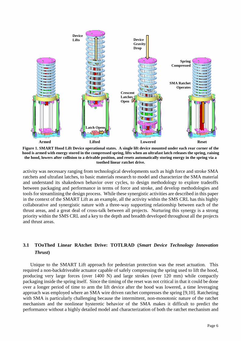
were conducted to explore the functional dependence of shakedown performance on loading and
strain history. SMA wires were thermally cycled under electrical heating under a range of applied
loads from 29 to 78 N (where the manufacturer‟s specification on the 15 mil diameter wire is 20 N)
and allowed strains from 4 to 7%. The steady-state and shakedown-rate performance was
characterized with a double-exponential empirical model fit to explore the functional dependence of
performance on loading conditions which was found to vary greatly (Figure 5). For example, the
absolute strain lost through shakedown was found to increase linearly both with maximum allowed
strain and with load applied, while relative motion loss varied only with applied load. Understanding
these relationships, allows the designer to incorporate shakedown in design decisions. For example,
tradeoffs can be made between motion produced and fatigue life by adjusting the allowed strain, or
between efficiency of material use and overall package length by varying the number of wires (or
wire diameter) sharing a load.
To develop a better understanding of the fundamental mechanism behind shakedown, further
experimental studies were conducted with the aim of supporting the development of a complete
shakedown model. Such a model would be useful, for example, to predict the shakedown response of
the complex loading conditions experienced in a toothed ratcheting device. These experimental
studies expose important shakedown parameters affecting SMA actuator performance and provide a
first step towards creating detailed SMA wire shakedown protocols tailored to the application that
will enable the design of higher performance stable SMA actuators.
Figure 4. Evolution of cyclic strain-temperature behavior of Flexinol wire at constant moderate (left) and high
(right) stress levels
Page 10
3.4 Shape Memory Alloy ReseTable (SMART) Latch (Smart Device Technology Innovation
Thrust)
Another key component to the SMART Lift device is the ultrafast slot latch which was
demonstrated to be capable of releasing the lifter in less than 4 ms to achieve precise lift times [32].
Latching is core to the SMS CRL because of its universal usage in the car for applications such as
closures [33] and reconfigurable crashworthiness [10], and is widely useful outside the automotive
industry, for example as electronic assembly latches or spacecraft door latches [34-36]. The SMS
CRL has developed both linear latches (i.e. SMART Lift), and rotary latches (i.e. panel lockdown)
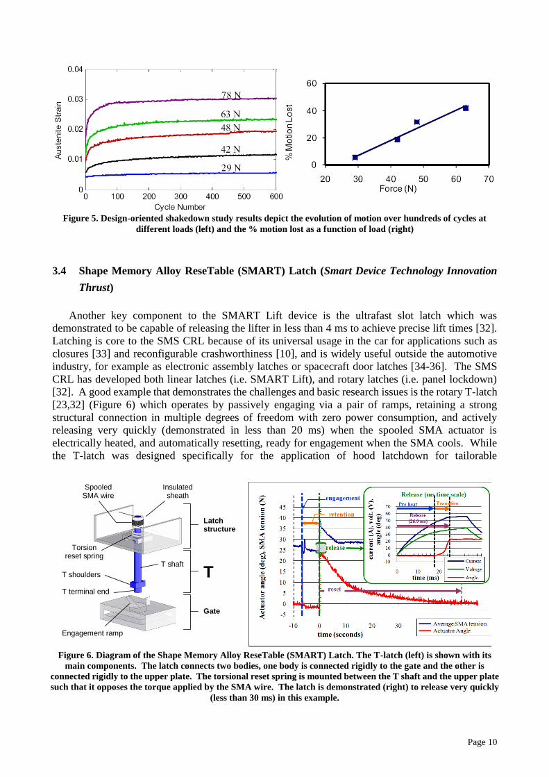
[32]. A good example that demonstrates the challenges and basic research issues is the rotary T-latch
[23,32] (Figure 6) which operates by passively engaging via a pair of ramps, retaining a strong
structural connection in multiple degrees of freedom with zero power consumption, and actively
releasing very quickly (demonstrated in less than 20 ms) when the spooled SMA actuator is
electrically heated, and automatically resetting, ready for engagement when the SMA cools. While
the T-latch was designed specifically for the application of hood latchdown for tailorable
Figure 5. Design-oriented shakedown study results depict the evolution of motion over hundreds of cycles at
different loads (left) and the % motion lost as a function of load (right)
Figure 6. Diagram of the Shape Memory Alloy ReseTable (SMART) Latch. The T-latch (left) is shown with its
main components. The latch connects two bodies, one body is connected rigidly to the gate and the other is
connected rigidly to the upper plate. The torsional reset spring is mounted between the T shaft and the upper plate
such that it opposes the torque applied by the SMA wire. The latch is demonstrated (right) to release very quickly
(less than 30 ms) in this example.
Latch structure
T
Gate
Spooled SMA wire
Insulated sheath
Torsion reset spring
T shaft
T shoulders
T terminal end
Engagement ramp

Page 11
crashworthiness, it represents a general technology which is captured by analytical operational
behavioral models based on a simplified constitutive law for SMA and first-order mechanics
regarding the loads applied to the T-latch throughout its operation. These predictive analytical
models were used to define design constraints ensuring feasible operation throughout the entire
latching cycle (engagement, retention, release, and reset). A full-scale T-latch prototype was
designed and built to meet standard automotive specifications for hood lockdown, and demonstrated
successfully, releasing extremely quickly (less than 20 ms) while requiring only minor amounts of
energy (about 20 J – a fraction of a percent of that stored in a typical AA battery). This work
motivated a study within the Design Methodology thrust area to better understand the design
tradeoffs between packaging, losses, and range of motion within spooled actuators. The ultrafast
latch development within the SMS CRL represents advancement over traditional latch technologies
with extremely fast release times, compact form factors, light weight, and small release energies with
the promise to improve upon and enable a wide range of devices both inside and outside the
automobile.
3.5 Packaging (Mechamatronic System Design Methodology Thrust)
The high energy density of SMA enables lightweight, low cost actuation but is limited by
packaging constraints. To provide large strokes, devices require long lengths of wire, while to
provide large forces, devices require either larger diameter wires or for shorter full cycles several
wires acting in parallel. Packaging for enhanced stroke and force while keeping within design
constraints is a challenge faced throughout the SMS CRL, particularly in the SMART lift which
requires large forces and strokes and in the T-latch which must provide large rotary motions in a very
compact form. Two of the primary packaging techniques studied in the SMS CRL are: spooling to
provide large stroke in a small package, and cabling to provide large forces in a simple form.
3.5.1 Spooling (stroke)
The spooled packaging technique wraps SMA wires around pulleys and mandrels for increased
compactness and tailorability while providing large linear or rotary motions. Spooling allows wires
to be routed to accommodate form factor constraints that do not otherwise allow long wires such as
was done in the SMART Lift device, and the actuator to be compacted down to as little as a single
mandrel to reduce the overall footprint such as was done in the T-latch. Spooling creates a design
tradeoff since form factor improvements come at the expense of friction losses between the SMA
wire and the mandrel surface and bending losses and potentially accelerated fatigue due to additional
bending strains. An analytical model was developed to relate the motion of a generalized spooled
actuator to its geometry, material properties, and the external load properties [37] (Figure 7). The
model accounts for distributed friction mechanics as well as the non-linear, phase and stress
dependent properties of the active material, and is flexible, accommodating a variety of
configurations including linear and rotational motion outputs and topologies involving multiple
spools. Experimental studies demonstrated the model‟s accuracy with respect to applied load, wrap
angle, and spool position and correlated very well with theory in both form and magnitude. Design
tradeoffs were exposed, for example, that increasing wrap angle reduces overall package size with a
tradeoff of reduced performance and an upper limit on the amount of packaging due to binding
[37,38]. Based on the results of this study, spooled packaging techniques and the accompanying

Page 12
predictive model provides a useful foundation for analytical actuator design for synthesizing high
performance actuators with compact packaging and minimized losses.
3.5.2 Cables (force)
While spooled packaging is aimed at providing increased stroke in a smaller package, SMA
cables are aimed at providing large forces in a compact, robust, easy to manage form factor. Applied
to either shape memory or superelastic alloys, this form has the potential to provide increased bending
flexibility for packaging, better fatigue performance, energy absorption and damping, reduced
thermal lag, redundancy, and significant design flexibility as compared to monolithic SMA rods of
comparable cross-sections. SMA cables have benefits over monolithic SMA elements as force or
displacement amplifiers and leverage the excellent properties of SMA wire in built-up large-scale
Figure 7. Spooled packaging model (left) predictions match experimental results at different wrap angles over a
range of loads (right).
Figure 8. Thermomechanical Response of the 7x7x0.239 mm SMA cable
Wire stress σ(M)
dSMAInput tail
length = ℓt,in
Fext – externally
applied load
State 0 wire, ε=0
State 1 wire, martensite (ξ(M)=1)
State 2 wire, austenite (ξ(M)=0)
ℓ - actuator
range of motion
R
Wrapped portion
length = ℓw
angle = θw
curvature = ρSMA
=(R + ½dSMA)-1
Output tail
0
,t out
,
A
t out
,
M
t out
Linearly sliding
motion output
Spool
Position
dsp = ℓt,in
A
A
0 5 10
0
5
10
15
20
0 50 100
Applied Load (N)
Str
ok
e (
mm
)
Applied stress (MPa)
strokedata fittheory
0 5 10
0
5
10
15
20
0 50 100
Applied Load (N)
Str
ok
e (
mm
)Applied stress (MPa)
strokedata fitμ=0.1μ=0.125

Page 13
tension structures. They also inherit many of the desirable attributes of conventional stranded rope in
terms of load carrying redundancy and increased bending compliance for packaging and spooling.
Exploratory thermomechanical experiments were conducted for a conventional cable design and its
sub-components [39] (Figure 8). The 7x7 design behaved similar to wires loaded in parallel, making
this design a natural choice for designers who wish to leverage the superior properties of SMA wires,
but need higher forces in a compact, easy to handle, and flexible package. Some important differences
do exist between the 7x7x0.279 mm cable and a single 0.279 mm straight wire: (1) an extra 1.3% of
transformation strain at the cost of about 40 MPa of loading plateau stress, and (2) a reaction torque
under zero-rotation constraint due to the chiral nature of the cable. Surprisingly, the reaction torque
has a maximum at the onset and a negative slope during the A → M+ transformation. Also,
self-heating/cooling effects and localized transformation are similar to that of straight Nitinol wire in
a range of loading rates. Experimental results also show nearly indistinguishable mechanical response
of a lubricated cable from a dry cable, a demonstration of the shape memory effect in an SMA cable,
and a relatively linear relationship between the axial plateau stresses and the specimen temperature.
In addition to demonstrating large forces in a convenient package the tests have shown that cables
with high helix angles (~50°) leverage displacement with recoverable „global‟ strains of ~12% as
compared to the low helix angle cables (~8°) which have strains similar to single SMA wires. These
initial experiments provide a preview of the advantages and design flexibility that SMA cables
provide.
3.6 SMA Wire Actuator Modular Design Framework (Mechamatronic System Design
Methodology Thrust)
As new design options become available such as spooled packaging and SMA ratchet drives, and
new fundamental knowledge is gained regarding material models, characterization, and shakedown
behavior, design tools are required which are modular and extensible in nature such that designers
with a variety of background and experience can incorporate these new developments into their
designs. The SMS CRL has developed the means of developing such tools centered on a modular
framework (Figure 9) upon which such tools can be based [40]. The inherently layered structure of
the SMA actuator design framework is broken up by function: modeling, evaluation, optimization,
and design guidance. Many of the components are represented as sets of “cards” which can be
switched to make local changes to the system. Optimization fits naturally under the framework since
the structure containing the identity and location of the design variables is clearly defined, as does
guidance through the design process based on various heuristics, expert experience, and discrete
optimization and automated design of experiment. An example design tool was implemented in
MATLAB based on the framework, and functions as an aid in the design of actuators employing
multiple straight SMA wires working in parallel against linearly varying (spring-like) and constant
quasi-static loads. This tool is powerful enough to allow a large variety of designs, and provide
detailed evaluation of design performance including automated parametric studies, but is structured
to guide the user through the actuator design process without requiring a deep knowledge into SMA
behavior. The developed tool is just an example of the variety of specialized and general purpose
design tools enabled by the framework which promise to enable designers with a variety of
backgrounds to overcome the difficulties involved in SMA wire actuator design, and to streamline the
wide use of SMA wire actuation in commercial and industrial applications.

Page 14
3.7 From Science to Technology Transition: The SMART Lift
The synergy among the work across all three thrust areas comes together to enable a fast
progression - blending basic research with application to produce technologies ready to be
transitioned to component suppliers for the automotive industry. The SMART hood lift device for
pedestrian protection is a prime example of such synergism, integrating advancements throughout the
SMS CRL. The architecture of the SMART hood lift device was built upon SMS CRL efforts from
the Technology Innovation thrust area on ultrafast latches for the release and lower functions, toothed
ratchet drives for reset, and spooled packaging to maintain a compact form within the interior of the
spring. The SMA wire actuators were designed with predictable performance with the aid of the
newly established tools and methodologies in the Design Methodology thrust area, where these tools
were based on the basic material understanding learned in the Smart Materials Maturity thrust area.
The device was designed based on analytical and simulation models of lift performance and full-scale
prototypes were built and installed in a hood lift vehicle testbed (Figure 10). The full functionality of
release, lift, automatic lower and reset were all repeatedly demonstrated, with ultrafast latch release
times of less than 4 ms and application-appropriate hood lift times just over 30ms. This enables the
SMART hood lift device to meet the demanding time window without damaging the hood and
provides the useful added adaptive functionality of automatic lower and reset upon a false deploy and
to de-energize when under-hood maintenance is required. This complicated technological success
was only possible in the quick time frame due to the synergistic interaction and indepth understanding
gained across all aspects of the CRL and the close communication.
Figure 9. Modular framework structure. The basic four layer design framework structure separates the
modeling, evaluation, optimization, and guidance functions into sub-function blocks within each layer
User Interface, Educate user, Identify design task, Aid Selection, Determine optimization
objectives
Material
Design
Evaluation
Design Guider
Optimizer
Architecture
Solution Process
Design Decisions
Data
Mapping Functions
σ, ε, T
Properties
Genetic Algorithm,
Simulated Annealing,
Fsolve, etc
Intersection
Solver
Actuated
System
Load
Profiles
Internal
Architecture,
External
Architecture,
Interfaces
Metrics for
Architecture,
Actuator,
Material
Gu
ide
r
La
ye
r
Mo
de
ling
La
ye
r
Eva
lua
tion
La
ye
r
Op
timiz
atio
n
La
ye
r

Page 15
4 CONCLUSIONS
This paper describes General Motors new collaborative research laboratory with the University of
Michigan in the area of smart materials and structures. The intent of the SMS CRL is to significantly
aid in leading the smart materials and structures field to a competitive status within the automotive
industry and impact the marketplace with revolutionary ideas and products that have the ability to
disrupt and redefine the industry. The mission of the SMS CRL is to establish the scientific
knowledge base and necessary design tools/methodologies while training the workforce leadership
required to exploit the emerging capabilities of smart materials and structures to create innovative
advanced device technologies for application within the automotive industry and extension to dual
technologies for strategic partners. This SMS CRL is unique in its breadth of approach, ranging from
basic research in the Smart Material Maturity Thrust, scientific methods in the Mechamatronic
System Design Methodology Thrust, to applied research in the Smart Device Technology Innovation
Thrust. Crucial to the success is the synergy gained through the close partnership between researchers
at General Motors, University of Michigan and other strategic partners based upon strong
cross-functional, cross-organization communication ties. The culture in the SMS CRL fosters a
strong synergy between projects and between thrust areas with a great deal of cross-pollination
ensuring that the work done has a broad and complete focus and that each project incorporates aspects
of basic science and technology application to maintain relevance. With the success of the variety of
research projects underway, many more significant advances are expected in the future years that will
have impact beyond General Motors and the automotive industry.
5 ACKNOWLEDGEMENTS
The authors would like to thank Alan Taub and Jan Aase from General Motors Research &
Development for their support and encouragement and for helping establish the SMS CRL as well as
VC Tom Stephens from General Motors and Dean David Munson from the University of Michigan
College of Engineering for their leadership of the General Motors / University of Michigan Institute
for Automotive Research and Education.
Figure 10. SMART Hood Lift Device developed by the SMS CRL. A single lift device (left) is mounted under each
rear corner of the hood in the vehicle testbed (middle) and can lift the rear of the hood more than 120 mm in just
over 30 ms (right).
Page 16
6 REFERENCES
1. M. Schwartz, “Encyclopedia of Smart Materials,” John Wiley and Sons, New York, NY, Vol. 1,
2002.
2. K. Uchino, “Servo displacement transducer applications,” Piezoelectric Actuators and Ultrasonic
Motors, ed. H. L. Tuller, Kluwer Academic Publishers, Massachusetts, USA, 217-244 (1997).
3. T. Morita, “Miniature piezoelectric motors,” Sensors and Actuators A: Physical, Vol. 103, No. 3,
pp. 291-300, 2003.
4. “Corvette Turns 50 with MagneRide,” Ward's Auto World, June 28, 2002.
5. T. Duerig, A. Pelton, and D. Stockel, “An Overview of nitinol medical applications,”
Proceedings of the International Conference on Martensitic Transformations, San Carlos de
Bariloche, pp. 149-160, 1999.
6. D. Brei, J. Luntz, J. Shaw, N. L. Johnson, A. L. Browne, P. W. Alexander, and N. D. Mankame,
“General Motors and the University of Michigan Smart Materials and Structures Collaborative
Research Laboratory,” Proceedings of SPIE International Symposium on Smart Structures and
Materials, SPIE Vol. 6527, San Diego, USA, 2007.
7. G. McKnight, A. L. Browne, and N. L. Johnson, “A Reversibly Deployable Air Dam: A Bending
Approach Based on Embedded Shape Memory Alloy Actuators, Part I: Design Approaches,”
Proceedings of Cansmart 2008.
8. G. McKnight, A. L. Browne, and N. L. Johnson, “A Reversibly Deployable Air Dam: A Bending
Approach Based on Embedded Shape Memory Alloy Actuators, Part II: Technology
Demonstration,” Proceedings of SPIE International Symposium on Smart Structures and
Materials, SPIE Vol. 7290, San Diego, USA, 2009.
9. B. Barnes, D. Brei, J. Luntz, A. L. Browne, and K. Strom, “Panel Deployment Using Ultrafast
SMA Latches,” Proceedings of ASME IMECE Conference, 2006-15026, 2006.
10. B. Barnes, D. Brei, J. Luntz, K. Strom, A. L. Browne, and N. Johnson, “Shape memory alloy
resettable spring lift for pedestrian protection,” Proceedings of SPIE International Symposium on
Smart Structures and Materials, SPIE Vol. 6930, San Diego, USA, 2008.
11. A. L. Browne, N. K. Bucknor, Y. T. Cheng, N. L. Johnson, W. C. Lin, C. S. Namuduri, Z. Sun and
P. Usoro, “Mechamatronics: An Automotive Perspective,” Proceedings of SPIE 11th
International Symposium on Smart Structures and Materials, SPIE Vol. 5388-54, San Diego,
USA, 14-18 March 2004.
12. Traffic Safety Facts 2001-Pedestrians, National Center for Statistics & Analysis (NCSA) of the
National Highway Traffic Safety Administration (NHTSA), U.S. Department of Transportation,
Washington, D.C., USA, 2001.
13. International Road Traffic and Accident Database (IRTAD), Federal Highway Research Institute
(BASt), Organization for Economic Co-operation and Development – Road Transport Research
Programme, Paris, France, 2001.
14. H. D. Taghirad, and E. Esmailzadeh, “Automobile passenger comfort assured through LQG/LQR
active suspension,” Journal of Vibration and Control, Vol. 4, pp. 603-618, 1998.
15. T. Aida, “Study of Human Head Impact: Brain Tissue Constitutive Models,” Ph.D. Thesis,
Department of Mechanical and Aerospace Engineering, Morgantown, West Virginia, 2000.
16. H. Sun, A. Pathak, J. Luntz, D. Brei, P. W. Alexander, and N. L. Johnson, “Stabilizing shape
memory alloy actuator performance through cyclic shakedown: An empirical study,”
Proceedings of SPIE International Symposium on Smart Structures and Materials, SPIE Vol.
6930, San Diego, USA, 2008.
17. C. B. Churchill, and J. Shaw, “Thermo-Electro-Mechanical Shakedown Response of Conditioned
Shape Memory Alloy Wires,” Proceedings of the ASME Conference on Smart Materials,
Adaptive Structures and Intelligent Systems, SMASIS2009-1306, Oxnard, USA, 2009.
18. B. Utter, J. Luntz, D. Brei, D. Teitelbaum, M. Okawada, and E. Miyasaka, “Design and operation

Page 17
of a fully implantable SMA actuated implant for correcting short bowel syndrome,” Proceedings
of SPIE International Symposium on Smart Structures and Materials, SPIE Vol. 6930, San Diego,
USA, 2008.
19. B. Utter, D. Brei, J. Luntz, D. Teitelbaum, M. Okawada, and E. Miyasaka, “Preliminary In Vivo
Experimental Validation Of SMA Based Bowel Extender For Short Bowel Syndrome,”
Proceedings of the ASME Conference on Smart Materials, Adaptive Structures and Intelligent
Systems, SMASIS2009-1458, Oxnard, USA, 2009.
20. Z. Bo, and D. C. Lagoudas, “Thermomechanical modeling of polycrystalline SMAs under cyclic
loading, Part I: Theoretical derivations,” International Journal of Engineering Science, Vol. 37,
No. 9, pp. 1089-1140, 1999.
21. D. J. Hartl, D. C. Lagoudas, “Constitutive modeling and structural analysis considering
simultaneous phase transformation and plastic yield in shape memory alloys,” Smart Materials
and Structures, Vol. 18, No. 10, pp. 104017 (17pp.), 2009.
22. B. Chang, J. A. Shaw, and M. A. Iadicola, “Thermodynamics of shape memory alloy wire:
modeling, experiments, and application,” Continuum Mechanics and Thermodynamics, Vol. 18,
No. 1-2, pp. 83-118, 2006.
23. J. A. Shaw, and C. B. Churchill, “A reduced-order thermomechanical model and analytical
solution for uniaxial shape memory alloy wire actuators,” Smart Materials and Structures, Vol.
18, No. 6, 2009.
24. S. Seelecke, and I. Müller, “Shape memory alloy actuators in smart structures: Modeling and
simulation,” Applied Mechanics Reviews, Vol. 57, pp. 23, 2004.
25. K. Tanaka, “A thermomechanical sketch of shape memory effect: one-dimensional tensile
behavior,” Res Mechanica, Vol. 18, No. 3, pp. 251-263, 1986.
26. C. Liang, and C.A. Rogers, “One-dimensional thermomechanical constitutive relations for shape
memory materials,” Journal of Intelligent Material Systems and Structures, Vol. 1, No. 2, pp. 207,
1990.
27. L. C. Brinson, “One-dimensional constitutive behavior of shape memory alloys:
thermomechanical derivation with non-constant material functions and redefined martensite
internal variable,” Journal of Intelligent Material Systems and Structures, Vol. 4, No. 2, pp. 229,
1993.
28. Y, Ivshin, and T. J. Pence, “A thermomechanical model for a one variant shape memory material,”
Journal of Intelligent Material Systems and Structures, Vol. 5, No. 4, pp. 455, 1994.
29. M. Achenbach, and I. Müller, “Simulation of material behavior of alloys with shape memory,”
Archiwum Mechaniki Stosowanej, Vol. 37, No. 6, pp. 573-585, 1985.
30. J. A. Shaw, C. B. Churchill, and M. A. Iadicola, “Tips and tricks for characterization shape
memory alloy wire: Part 1. Differential scanning calorimetry and basic phenomena,”
Experimental Techniques, Vol. 32, No. 5, pp. 55-62, 2008.
31. C. B. Churchill, J. A. Shaw, and M. A. Iadicola, “Tips and tricks for characterization shape
memory alloy wire: Part 2 – fundamental isothermal responses,” Experimental Techniques, Vol.
33, No. 1, pp. 51-62, 2009.
32. J. A. Redmond, D. Brei, J. Luntz, A. L. Browne, N. L. Johnson, and S. A. Kenneth, “The design
and experimental validation of an ultrafast smart (SMA resettable) latch,” Proceedings of ASME
IMECE Conference, v 10 Part A, pp. 315-326, 2007.
33. “Fiat designs new door lock,” Automotive News Europe, January 1, 2004.
34. ITW Global Appliance Group, “Door Locks,” Retrieved October 9, 2007, from
http://www.itwglobalappliance.com/products/door_locks.htm.
35. M. Lucy, R. Hardy, E. Kist, “Report on Alternative Devices to Pyrotechnics on Spacecraft,”
NASA Langley Research Center, Hampton, VA, pp. 1-22, 1996.
36. T. E. McCloskey, “Non-pyrotechnic release system,” Application 753,556, Filed September 3,
1991, Patent 5,192,147, Issued March 9, 1993.

Page 18
37. J. A. Redmond, D. Brei, J. Luntz, A. L. Browne, and N. L. Johnson, “Behavioral model and
experimental validation for a spool-packaged shape memory alloy actuator,” Proceedings of
SPIE International Symposium on Smart Structures and Materials, SPIE Vol. 6930, San Diego,
USA, 2008.
38. J. A. Redmond, D. Brei, J. Luntz, A. L. Browne, and N. L. Johnson, “Effect of bending on the
performance of spool-packaged shape memory alloy actuator,” Proceedings of SPIE
International Symposium on Smart Structures and Materials, SPIE Vol. 7290, San Diego, USA,
2009.
39. B. Reedlunn, J. Shaw and D. Samantha, “Shape Memory Alloy Cables: Exploratory Experiments,”
Proceedings of the ASME Conference on Smart Materials, Adaptive Structures and Intelligent
Systems, SMASIS2009-1311, Oxnard, USA, 2009.
40. J. Luntz, B. Barnes, D. Brei, P. Alexander, A. Browne, and N. Johnson, “SMA wire actuator
modular design framework,” Proceedings of SPIE International Symposium on Smart Structures
and Materials, SPIE Vol. 7290, San Diego, USA, 2009.