Embed Size (px)
Citation preview
© KEMET Electronics Corporation • P.O. Box 5928 • Greenville, SC 29606 • 864-963-6300 • www.kemet.com T2073_T59X • 5/29/2018 1One world. One KEMET
Benefits
• Ultra low ESR • FullcompliancewithAEC–Q200qualificationtestplan
(T598 125°C, T599 150°C)• QualificationplanbasedonAEC–Q200with85°C/85%RHloadspecificationlimitedto500hours(T591)
• TS16949certifiedplant• SubjecttoPPAP/PSWandchangecontrol• MeetsorexceedsEIAstandard535BAAC• TapedandreeledperEIA481• Halogen-free,epoxyandRoHScompliant
Overview
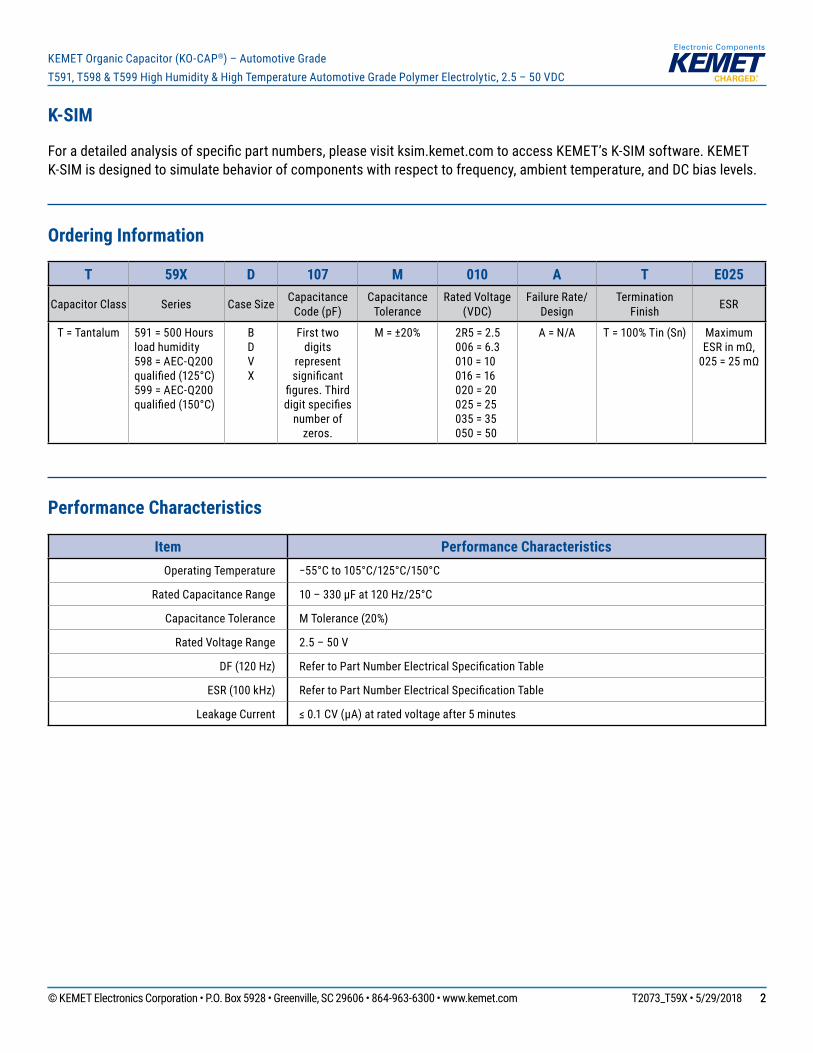
TheKEMETOrganicCapacitor(KO-CAP)isasolidelectrolyticcapacitorwithaconductivepolymercathode,capableofdeliveringverylowESRandanimprovedcapacitanceretentionathighfrequencies.KO-CAPcombinesthelowESRofthemultilayerceramic,thehighcapacitanceofaluminumelectrolyticandthevolumetricefficiencyoftantalumintoasinglesurfacemountpackage.Unlikeliquidelectrolyte-basedcapacitors,KO-CAPhasaverylongoperationallifeandhighripplecurrentcapabilities.
TheT591/T598/T599HighHumidityandHighTemperaturePolymerElectrolyticcapacitorsdeliverhighercapacitanceandESRstabilityunderharshenvironmentalconditions.Enhancementstothedesignandselectedmaterialupgradeswereintroducedtodeliver500hours(T591)or1,000hours(T598,T599)at85°C/85%RHratedvoltageandtofullycomplywiththeAEC-Q200qualificationtestingwithmaximumoperationaltemperaturelifeupto125°Cand150°Crespectively.ThesecapacitorsaremanufacturedinanISOTS16949certifiedplantandaresubjectedtoPPAP/PSW,aswellaschangecontrol.
KEMETOrganicCapacitor(KO-CAP®)–AutomotiveGrade
T591, T598 & T599 High Humidity & High Temperature Automotive Grade Polymer Electrolytic, 2.5 – 50 VDC
Applications
Typicalapplicationsincludedecouplingandfilteringinavarietyofmarketsegments,withspecialemphasisinautomotiveapplicationssuchasinfotainment,ADAS,chassisandsafety,aswellaspowertrain,whereharshconditions,suchashighhumidityandtemperature,areaconcern.
Environmental Compliance
RoHScompliant(6/6)accordingtoDirective2002/95/ECwhenorderedwith100%Snsolder.Halogen-free.
© KEMET Electronics Corporation • P.O. Box 5928 • Greenville, SC 29606 • 864-963-6300 • www.kemet.com T2073_T59X • 5/29/2018 22
KEMET Organic Capacitor (KO-CAP®) – Automotive GradeT591, T598 & T599 High Humidity & High Temperature Automotive Grade Polymer Electrolytic, 2.5 – 50 VDC
K-SIM
Foradetailedanalysisofspecificpartnumbers,pleasevisitksim.kemet.comtoaccessKEMET’sK-SIMsoftware.KEMETK-SIMisdesignedtosimulatebehaviorofcomponentswithrespecttofrequency,ambienttemperature,andDCbiaslevels.
Ordering Information
T 59X D 107 M 010 A T E025
Capacitor Class Series Case Size Capacitance Code(pF)
Capacitance Tolerance
RatedVoltage(VDC)
Failure Rate/ Design
TerminationFinish ESR
T = Tantalum 591=500Hoursloadhumidity598 = AEC-Q200 qualified(125°C)599 = AEC-Q200 qualified(150°C)
B D V X
First two digits
represent significant
figures.Thirddigitspecifiesnumberof
zeros.
M=±20% 2R5 = 2.5 006 = 6.3 010 = 10 016 = 16 020 = 20 025 = 25 035 = 35 050 = 50
A = N/A T=100%Tin(Sn) Maximum ESRinmΩ, 025=25mΩ
Performance Characteristics
Item Performance CharacteristicsOperatingTemperature −55°Cto105°C/125°C/150°C
RatedCapacitanceRange 10–330µFat120Hz/25°C
Capacitance Tolerance MTolerance(20%)
RatedVoltageRange 2.5–50V
DF(120Hz) RefertoPartNumberElectricalSpecificationTable
ESR(100kHz) RefertoPartNumberElectricalSpecificationTable
LeakageCurrent ≤0.1CV(µA)atratedvoltageafter5minutes
© KEMET Electronics Corporation • P.O. Box 5928 • Greenville, SC 29606 • 864-963-6300 • www.kemet.com T2073_T59X • 5/29/2018 33
KEMET Organic Capacitor (KO-CAP®) – Automotive GradeT591, T598 & T599 High Humidity & High Temperature Automotive Grade Polymer Electrolytic, 2.5 – 50 VDC
Qualification
Test Condition Characteristics
Endurance
105°Catratedvoltage,2,000hours 125°Cat2/3ratedvoltage,2,000hours (for≤16Vparts)** 125°Cat2/3ratedvoltage,1,000hours (for>16Vparts)** 150°Cat2/3ratedvoltage,1,000hours(T599)
ΔC/C Within−20%/+10%ofinitialvalue
DF Within2xinitiallimitDCL Within2xinitiallimitESR Within2xinitiallimit
StorageLife105°C at 0 volts, 2,000 hours125°Cat0volts,1,000hours**150°C at 0 volts, 1,000 hours (T599)
ΔC/C Within−20%/+10%ofinitialvalueDF Within2xinitiallimitDCL Within2xinitiallimitESR Within2xinitiallimit
Humidity 85°C,85%RH,load,500hours(T591)85°C,85%RH,load,1,000hours(T598,T599)
ΔC/C Within−5%/+35%ofinitialvalueDF Within1.5xinitiallimitsDCL WithininitiallimitESR Within2xinitiallimit
Moisture Resistance*
MIL–STD–202,Method106,65°C,90–100%RH,noload,10cycles
ΔC/C Within−10%/+20%ofinitialvalueDF WithininitiallimitDCL WithininitiallimitESR Within2xinitiallimit
Temperature Cycling
JESD22,TestMethodA104, −55°Cto+105°C/+125°C/+150°C**,1,000cycles
ΔC/C Within−20%/+10%ofinitialvalueDF WithininitiallimitsDCL WithininitiallimitESR Within2xinitiallimits
SurgeVoltage
105°C,1.32xratedvoltage,1,000cycles,33Ωinseries125°C/150°C,1.32x(0.67xVR),1,000cycles,33Ωinseries**
ΔC/C Within−20%/+10%ofinitialvalueDF WithininitiallimitsDCL WithininitiallimitsESR Withininitiallimits
Temperature Stability
Extreme temperature exposure at a successionofcontinuousstepsat +25°C,−55°C,+25°C,+85°C,+105°C/+125°C/+150°C**,+25°C
+25°C −55°C +85°C +105°C/+125°C/+150°C**ΔC/C IL*** ±20% ±20% ±30%DF IL IL 1.2xIL 1.5xILDCL IL N/A 10xIL 10xIL
Mechanical Shock/Vibration
AEC–Q200(MIL–STD–202,Method213,Figure1,ConditionF.)
ΔC/C Within±10%ofinitialvalueDF Withininitiallimits
AEC–Q200(MIL–STD–202,Method204,5gfor20minutes/12cycleseachof3orientations.Testfrom10–2,000Hz.)
ESR Withininitiallimits
DCL Withininitiallimits
* T598 only** Refer to part number specifications for individual temperature classification*** IL = Initial limit
© KEMET Electronics Corporation • P.O. Box 5928 • Greenville, SC 29606 • 864-963-6300 • www.kemet.com T2073_T59X • 5/29/2018 44
KEMET Organic Capacitor (KO-CAP®) – Automotive GradeT591, T598 & T599 High Humidity & High Temperature Automotive Grade Polymer Electrolytic, 2.5 – 50 VDC
Reliability
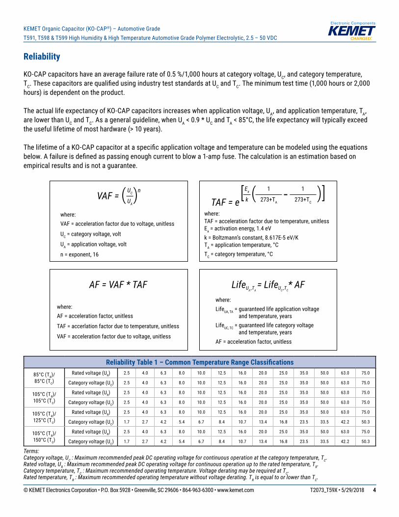
KO-CAPcapacitorshaveanaveragefailurerateof0.5%/1,000hoursatcategoryvoltage,UC,andcategorytemperature,TC.ThesecapacitorsarequalifiedusingindustryteststandardsatUCandTC. The minimum test time (1,000 hours or 2,000 hours)isdependentontheproduct.
TheactuallifeexpectancyofKO-CAPcapacitorsincreaseswhenapplicationvoltage,UA,andapplicationtemperature,TA, are lower than UCandTC.Asageneralguideline,whenUA<0.9*UCandTA<85°C,thelifeexpectancywilltypicallyexceedtheusefullifetimeofmosthardware(>10years).
ThelifetimeofaKO-CAPcapacitorataspecificapplicationvoltageandtemperaturecanbemodeledusingtheequationsbelow.Afailureisdefinedaspassingenoughcurrenttoblowa1-ampfuse.Thecalculationisanestimationbasedonempiricalresultsandisnotaguarantee.
TAF = e[ ( )]Ea
k
1
273+TA
1
273+TC
TAF = acceleration factor due to temperature, unitlesswhere:
Ea = activation energy, 1.4 eVk = Boltzmann’s constant, 8.617E-5 eV/KTA = application temperature, °CTC = category temperature, °C
VAF = ( )UC
UA
n
VAF = acceleration factor due to voltage, unitlesswhere:
UC = category voltage, volt
UA = application voltage, volt
n = exponent, 16
AF = VAF * TAF
AF = acceleration factor, unitlesswhere:
TAF = accerlation factor due to temperature, unitless
VAF = acceleration factor due to voltage, unitless
* AFLifeUA ,TA= LifeUC ,TC
LifeUA, TA = guaranteed life application voltage and temperature, years
where:
AF = acceleration factor, unitless
LifeUC, TC = guaranteed life category voltage and temperature, years
Reliability Table 1 – Common Temperature Range Classifications85°C (TR)/ 85°C (TC)
Ratedvoltage(UR) 2.5 4.0 6.3 8.0 10.0 12.5 16.0 20.0 25.0 35.0 50.0 63.0 75.0
Categoryvoltage(UC) 2.5 4.0 6.3 8.0 10.0 12.5 16.0 20.0 25.0 35.0 50.0 63.0 75.0
105°C (TR)/ 105°C (TC)
Ratedvoltage(UR) 2.5 4.0 6.3 8.0 10.0 12.5 16.0 20.0 25.0 35.0 50.0 63.0 75.0
Categoryvoltage(UC) 2.5 4.0 6.3 8.0 10.0 12.5 16.0 20.0 25.0 35.0 50.0 63.0 75.0
105°C (TR)/ 125°C (TC)
Ratedvoltage(UR) 2.5 4.0 6.3 8.0 10.0 12.5 16.0 20.0 25.0 35.0 50.0 63.0 75.0
Categoryvoltage(UC) 1.7 2.7 4.2 5.4 6.7 8.4 10.7 13.4 16.8 23.5 33.5 42.2 50.3
105°C (TR)/ 150°C (TC)
Ratedvoltage(UR) 2.5 4.0 6.3 8.0 10.0 12.5 16.0 20.0 25.0 35.0 50.0 63.0 75.0
Categoryvoltage(UC) 1.7 2.7 4.2 5.4 6.7 8.4 10.7 13.4 16.8 23.5 33.5 42.2 50.3
Terms:Category voltage, UC : Maximum recommended peak DC operating voltage for continuous operation at the category temperature, TC.Rated voltage, UR : Maximum recommended peak DC operating voltage for continuous operation up to the rated temperature, TR.Category temperature, TC : Maximum recommended operating temperature. Voltage derating may be required at TC.Rated temperature, TR : Maximum recommended operating temperature without voltage derating. TR is equal to or lower than TC.
© KEMET Electronics Corporation • P.O. Box 5928 • Greenville, SC 29606 • 864-963-6300 • www.kemet.com T2073_T59X • 5/29/2018 55
KEMET Organic Capacitor (KO-CAP®) – Automotive GradeT591, T598 & T599 High Humidity & High Temperature Automotive Grade Polymer Electrolytic, 2.5 – 50 VDC
Certification
KEMET'sinternalqualificationplanforthispolymerelectrolyticseriesofcapacitorsfollowsAEC-Q200guidelines. ForT591thehumiditybiasislimitedtoamaximumof500hours.ForT598thequalificationplanisfullycompliantwithAEC-Q200withmaximumoperationaltemperatureof125°C.ForT599thequalificationplanisfullycompliantwithAEC-Q200withmaximumoperationaltemperatureof150°C.
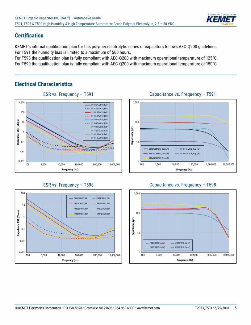
Electrical Characteristics
100
1,000
1
Capa
cita
nce
(µF)
Frequency (Hz)
100 1,000 10,000 100,000 1,000,000 10,000,000
10
598B476M010_Cap (µF) 598D107M010_Cap (µF)
598D227M010_Cap (µF) 598D107M016_Cap (µF)
Capacitancevs.Frequency–T598ESRvs.Frequency–T598
Impe
danc
e, E
SR (O
hms)
Frequency (Hz)
100
10
1
0.1
0.01
0.001100 1,000 10,000 100,000 1,000,000 10,000,000
598B476M010_IMP 598B476M010_ESR
598D107M010_IMP 598D107M010_ESR
598D227M010_IMP 598D227M010_ESR
598D107M016_IMP 598D107M016_ESR
100
1,000
1
Capa
cita
nce
(µF)
Frequency (Hz)
100 1,000 10,000 100,000 1,000,000 10,000,000
10
591B476M010_Cap (µF)
591D107M010_Cap (µF)
591V227M2R5_Cap (µF)
591D106M050_Cap (µF)
591D476M016_Cap (µF)
Capacitancevs.Frequency–T591ESRvs.Frequency–T591
Impe
danc
e, E
SR (O
hms)
Frequency (Hz)
1,000
100
10
1
0.1
0.01
0.001100 1,000 10,000 100,000 1,000,000 10,000,000
591B476M010_IMP
591B476M010_ESR
591D107M010_IMP
591D107M010_ESR
591D476M016_IMP
591D476M016_ESR
591V227M2R5_IMP
591V227M2R5_ESR
591D106M050_IMP
591D106M050_ESR
© KEMET Electronics Corporation • P.O. Box 5928 • Greenville, SC 29606 • 864-963-6300 • www.kemet.com T2073_T59X • 5/29/2018 66
KEMET Organic Capacitor (KO-CAP®) – Automotive GradeT591, T598 & T599 High Humidity & High Temperature Automotive Grade Polymer Electrolytic, 2.5 – 50 VDC
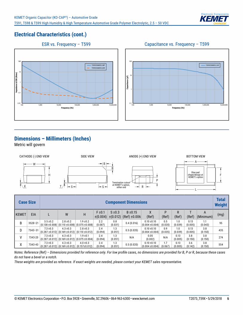
Electrical Characteristics (cont.)
Capa
cita
nce
(µF)
Frequency (Hz)1,000,000 10,000,0001,000 10,000 100,000100
0.1
1
10
100
T599X336M035_CAP
Capacitancevs.Frequency–T599ESRvs.Frequency–T599
Impe
danc
e &
ESR
(0hm
s)
Frequency (Hz)1,000,000 10,000,0001,000 10,000 100,000100
0.01
0.1
1
10
100
T599X336M035_IMP
T599X336M035_ESR
Dimensions – Millimeters (Inches)Metricwillgovern
H
X T
B B
F
A
L R
P
SIDE VIEW ANODE (+) END VIEW BOTTOM VIEWCATHODE (-) END VIEW
W
S STermination cutout at KEMET's option,
either end
Glue pad shape/design at KEMET's option
Case Size Component Dimensions Total Weight
KEMET EIA L W H F ±0.1 ±(0.004)
S ±0.3 ±(0.012)
B ±0.15 (Ref)±0.006
X (Ref)
P (Ref)
R (Ref)
T (Ref)
A (Minimum) (mg)
B 3528–21 3.5 ±0.2 (0.138 ±0.008)
2.8 ±0.2 (0.110 ±0.008)
1.9 ±0.2 (0.075 ±0.008)
2.2 (0.087)
0.8 (0.031) 0.4 (0.016) 0.10 ±0.10
(0.004 ±0.004)0.5
(0.020)1.0
(0.039)0.13
(0.005)1.1
(0.043) 95
D 7343–31 7.3 ±0.3 (0.287 ±0.012)
4.3 ±0.3 (0.169 ±0.012)
2.8 ±0.3 (0.110 ±0.012)
2.4 (0.094)
1.3 (0.051) 0.5 (0.020) 0.10 ±0.10
(0.004 ±0.004)0.9
(0.035)1.0
(0.039)0.13
(0.005)3.8
(0.150) 435
V 7343-20 7.3 ±0.3 (0.287 ±0.012)
4.3 ±0.3 (0.169 ±0.012)
1.9 ±0.1 (0.075 ±0.004)
2.4 (0.094)
1.3 (0.051) N/A 0.05
(0.002) N/A 0.13 (0.005)
3.8 (0.150)
3.8 (0.150) 274
X 7343-43 7.3 ±0.3 (0.287 ±0.012)
4.3 ±0.3 (0.169 ±0.012)
4.0 ±0.3 (0.157±0.012)
2.4 (0.094)
1.3 (0.051) 0.5 (0.020) 0.10 ±0.10
(0.004 ±0.004)1.7
(0.067)0.13
(0.005)3.6
(0.142)3.8
(0.150) 554
Notes: Reference (Ref) – Dimensions provided for reference only. For low profile cases, no dimensions are provided for B, P or R, because these cases do not have a bevel or a notch.These weights are provided as reference. If exact weights are needed, please contact your KEMET sales representative.
© KEMET Electronics Corporation • P.O. Box 5928 • Greenville, SC 29606 • 864-963-6300 • www.kemet.com T2073_T59X • 5/29/2018 77
KEMET Organic Capacitor (KO-CAP®) – Automotive GradeT591, T598 & T599 High Humidity & High Temperature Automotive Grade Polymer Electrolytic, 2.5 – 50 VDC
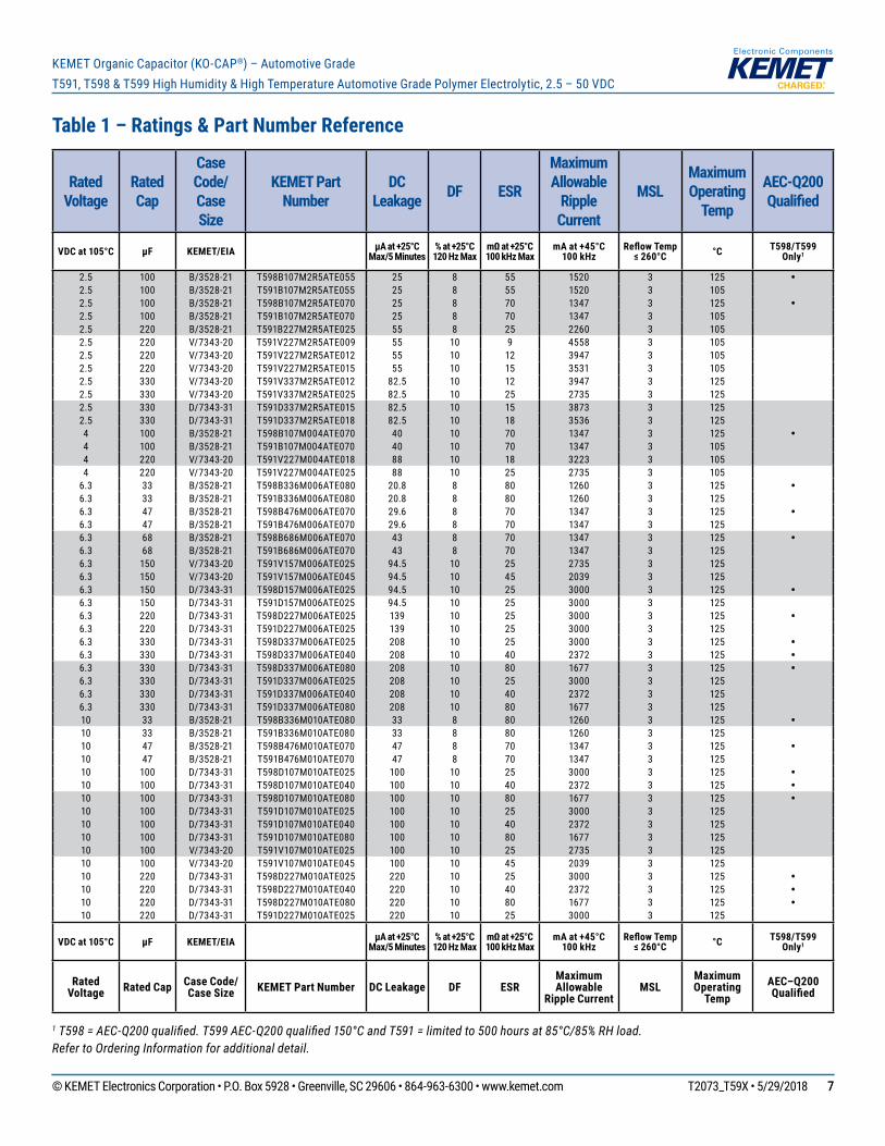
Table 1 – Ratings & Part Number Reference
1 T598 = AEC-Q200 qualified. T599 AEC-Q200 qualified 150°C and T591 = limited to 500 hours at 85°C/85% RH load.Refer to Ordering Information for additional detail.
Rated Voltage
Rated Cap
Case Code/ Case Size
KEMET Part Number
DC Leakage DF ESR
Maximum Allowable
Ripple Current
MSLMaximum Operating
Temp
AEC-Q200 Qualified
VDC at 105°C µF KEMET/EIA µA at +25°CMax/5 Minutes
% at +25°C120 Hz Max
mΩ at +25°C100 kHz Max
mA at +45°C 100 kHz
Reflow Temp ≤ 260°C °C T598/T599
Only1
2.5 100 B/3528-21 T598B107M2R5ATE055 25 8 55 1520 3 125 •2.5 100 B/3528-21 T591B107M2R5ATE055 25 8 55 1520 3 1052.5 100 B/3528-21 T598B107M2R5ATE070 25 8 70 1347 3 125 •2.5 100 B/3528-21 T591B107M2R5ATE070 25 8 70 1347 3 1052.5 220 B/3528-21 T591B227M2R5ATE025 55 8 25 2260 3 1052.5 220 V/7343-20 T591V227M2R5ATE009 55 10 9 4558 3 1052.5 220 V/7343-20 T591V227M2R5ATE012 55 10 12 3947 3 1052.5 220 V/7343-20 T591V227M2R5ATE015 55 10 15 3531 3 1052.5 330 V/7343-20 T591V337M2R5ATE012 82.5 10 12 3947 3 1252.5 330 V/7343-20 T591V337M2R5ATE025 82.5 10 25 2735 3 1252.5 330 D/7343-31 T591D337M2R5ATE015 82.5 10 15 3873 3 1252.5 330 D/7343-31 T591D337M2R5ATE018 82.5 10 18 3536 3 1254 100 B/3528-21 T598B107M004ATE070 40 10 70 1347 3 125 •4 100 B/3528-21 T591B107M004ATE070 40 10 70 1347 3 1054 220 V/7343-20 T591V227M004ATE018 88 10 18 3223 3 1054 220 V/7343-20 T591V227M004ATE025 88 10 25 2735 3 105
6.3 33 B/3528-21 T598B336M006ATE080 20.8 8 80 1260 3 125 •6.3 33 B/3528-21 T591B336M006ATE080 20.8 8 80 1260 3 1256.3 47 B/3528-21 T598B476M006ATE070 29.6 8 70 1347 3 125 •6.3 47 B/3528-21 T591B476M006ATE070 29.6 8 70 1347 3 1256.3 68 B/3528-21 T598B686M006ATE070 43 8 70 1347 3 125 •6.3 68 B/3528-21 T591B686M006ATE070 43 8 70 1347 3 1256.3 150 V/7343-20 T591V157M006ATE025 94.5 10 25 2735 3 1256.3 150 V/7343-20 T591V157M006ATE045 94.5 10 45 2039 3 1256.3 150 D/7343-31 T598D157M006ATE025 94.5 10 25 3000 3 125 •6.3 150 D/7343-31 T591D157M006ATE025 94.5 10 25 3000 3 1256.3 220 D/7343-31 T598D227M006ATE025 139 10 25 3000 3 125 •6.3 220 D/7343-31 T591D227M006ATE025 139 10 25 3000 3 1256.3 330 D/7343-31 T598D337M006ATE025 208 10 25 3000 3 125 •6.3 330 D/7343-31 T598D337M006ATE040 208 10 40 2372 3 125 •6.3 330 D/7343-31 T598D337M006ATE080 208 10 80 1677 3 125 •6.3 330 D/7343-31 T591D337M006ATE025 208 10 25 3000 3 1256.3 330 D/7343-31 T591D337M006ATE040 208 10 40 2372 3 1256.3 330 D/7343-31 T591D337M006ATE080 208 10 80 1677 3 12510 33 B/3528-21 T598B336M010ATE080 33 8 80 1260 3 125 •10 33 B/3528-21 T591B336M010ATE080 33 8 80 1260 3 12510 47 B/3528-21 T598B476M010ATE070 47 8 70 1347 3 125 •10 47 B/3528-21 T591B476M010ATE070 47 8 70 1347 3 12510 100 D/7343-31 T598D107M010ATE025 100 10 25 3000 3 125 •10 100 D/7343-31 T598D107M010ATE040 100 10 40 2372 3 125 •10 100 D/7343-31 T598D107M010ATE080 100 10 80 1677 3 125 •10 100 D/7343-31 T591D107M010ATE025 100 10 25 3000 3 12510 100 D/7343-31 T591D107M010ATE040 100 10 40 2372 3 12510 100 D/7343-31 T591D107M010ATE080 100 10 80 1677 3 12510 100 V/7343-20 T591V107M010ATE025 100 10 25 2735 3 12510 100 V/7343-20 T591V107M010ATE045 100 10 45 2039 3 12510 220 D/7343-31 T598D227M010ATE025 220 10 25 3000 3 125 •10 220 D/7343-31 T598D227M010ATE040 220 10 40 2372 3 125 •10 220 D/7343-31 T598D227M010ATE080 220 10 80 1677 3 125 •10 220 D/7343-31 T591D227M010ATE025 220 10 25 3000 3 125
VDC at 105°C µF KEMET/EIA µA at +25°CMax/5 Minutes
% at +25°C120 Hz Max
mΩ at +25°C100 kHz Max
mA at +45°C 100 kHz
Reflow Temp ≤ 260°C °C T598/T599
Only1
Rated Voltage Rated Cap Case Code/
Case Size KEMET Part Number DC Leakage DF ESRMaximum Allowable
Ripple CurrentMSL
Maximum Operating
TempAEC–Q200 Qualified
© KEMET Electronics Corporation • P.O. Box 5928 • Greenville, SC 29606 • 864-963-6300 • www.kemet.com T2073_T59X • 5/29/2018 88
KEMET Organic Capacitor (KO-CAP®) – Automotive GradeT591, T598 & T599 High Humidity & High Temperature Automotive Grade Polymer Electrolytic, 2.5 – 50 VDC
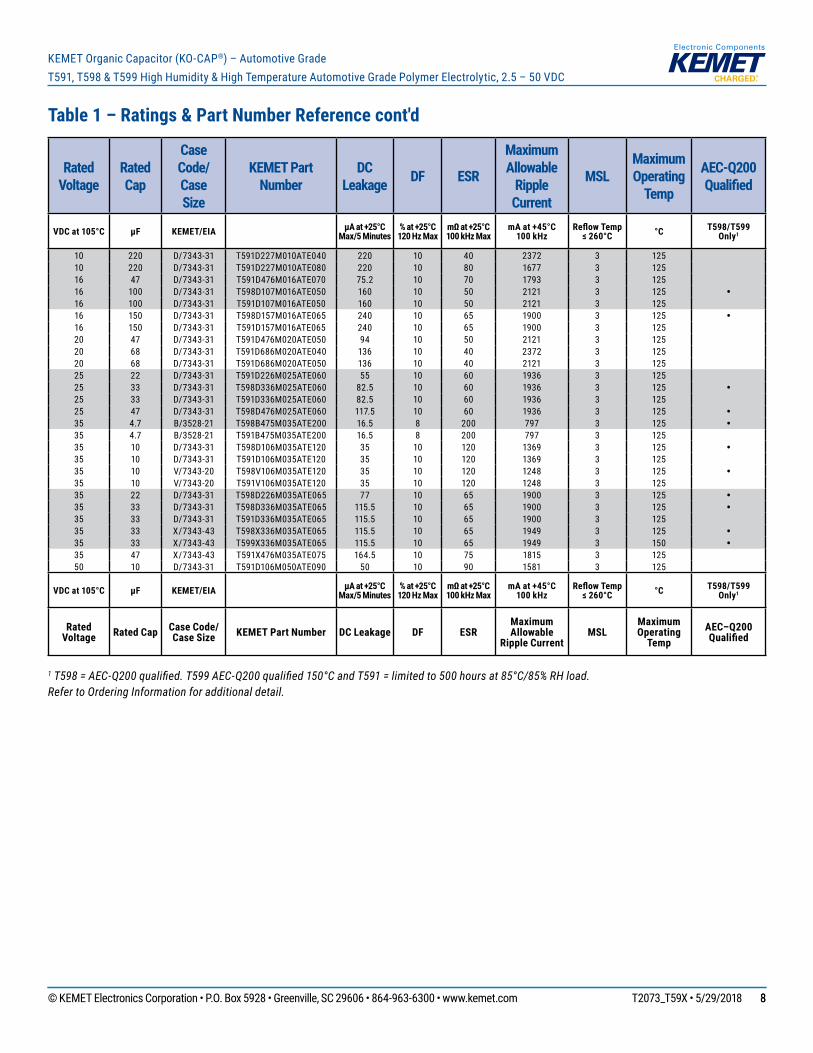
Table 1 – Ratings & Part Number Reference cont'd
1 T598 = AEC-Q200 qualified. T599 AEC-Q200 qualified 150°C and T591 = limited to 500 hours at 85°C/85% RH load.Refer to Ordering Information for additional detail.
Rated Voltage
Rated Cap
Case Code/ Case Size
KEMET Part Number
DC Leakage DF ESR
Maximum Allowable
Ripple Current
MSLMaximum Operating
Temp
AEC-Q200 Qualified
VDC at 105°C µF KEMET/EIA µA at +25°CMax/5 Minutes
% at +25°C120 Hz Max
mΩ at +25°C100 kHz Max
mA at +45°C 100 kHz
Reflow Temp ≤ 260°C °C T598/T599
Only1
10 220 D/7343-31 T591D227M010ATE040 220 10 40 2372 3 12510 220 D/7343-31 T591D227M010ATE080 220 10 80 1677 3 12516 47 D/7343-31 T591D476M016ATE070 75.2 10 70 1793 3 12516 100 D/7343-31 T598D107M016ATE050 160 10 50 2121 3 125 •16 100 D/7343-31 T591D107M016ATE050 160 10 50 2121 3 12516 150 D/7343-31 T598D157M016ATE065 240 10 65 1900 3 125 •16 150 D/7343-31 T591D157M016ATE065 240 10 65 1900 3 12520 47 D/7343-31 T591D476M020ATE050 94 10 50 2121 3 12520 68 D/7343-31 T591D686M020ATE040 136 10 40 2372 3 12520 68 D/7343-31 T591D686M020ATE050 136 10 40 2121 3 12525 22 D/7343-31 T591D226M025ATE060 55 10 60 1936 3 12525 33 D/7343-31 T598D336M025ATE060 82.5 10 60 1936 3 125 •25 33 D/7343-31 T591D336M025ATE060 82.5 10 60 1936 3 12525 47 D/7343-31 T598D476M025ATE060 117.5 10 60 1936 3 125 •35 4.7 B/3528-21 T598B475M035ATE200 16.5 8 200 797 3 125 •35 4.7 B/3528-21 T591B475M035ATE200 16.5 8 200 797 3 12535 10 D/7343-31 T598D106M035ATE120 35 10 120 1369 3 125 •35 10 D/7343-31 T591D106M035ATE120 35 10 120 1369 3 12535 10 V/7343-20 T598V106M035ATE120 35 10 120 1248 3 125 •35 10 V/7343-20 T591V106M035ATE120 35 10 120 1248 3 12535 22 D/7343-31 T598D226M035ATE065 77 10 65 1900 3 125 •35 33 D/7343-31 T598D336M035ATE065 115.5 10 65 1900 3 125 •35 33 D/7343-31 T591D336M035ATE065 115.5 10 65 1900 3 12535 33 X/7343-43 T598X336M035ATE065 115.5 10 65 1949 3 125 •35 33 X/7343-43 T599X336M035ATE065 115.5 10 65 1949 3 150 •35 47 X/7343-43 T591X476M035ATE075 164.5 10 75 1815 3 12550 10 D/7343-31 T591D106M050ATE090 50 10 90 1581 3 125
VDC at 105°C µF KEMET/EIA µA at +25°CMax/5 Minutes
% at +25°C120 Hz Max
mΩ at +25°C100 kHz Max
mA at +45°C 100 kHz
Reflow Temp ≤ 260°C °C T598/T599
Only1
Rated Voltage Rated Cap Case Code/
Case Size KEMET Part Number DC Leakage DF ESRMaximum Allowable
Ripple CurrentMSL
Maximum Operating
TempAEC–Q200 Qualified

© KEMET Electronics Corporation • P.O. Box 5928 • Greenville, SC 29606 • 864-963-6300 • www.kemet.com T2073_T59X • 5/29/2018 99
KEMET Organic Capacitor (KO-CAP®) – Automotive GradeT591, T598 & T599 High Humidity & High Temperature Automotive Grade Polymer Electrolytic, 2.5 – 50 VDC
Derating Guidelines
50%
55%
60%
65%
70%
75%
80%
85%
90%
95%
100%
−55 25 45 85 105 125
Recommended Application Voltage ≥ 16 V
Rated Voltage
Recommended Application Voltage VR ≤ 10 V
67%
60%
54%
% Ra
ted
Volta
ge
Temperature (˚C)
67%
60%
54%
% Ra
ted
Volta
ge
Temperature (°C)
50%
55%
60%
65%
70%
75%
80%
85%
90%
95%
100%
−55 25 45 85 105 125 150
Recommended Application Voltage ≥ 16 V
Rated Voltage
Recommended Application Voltage VR ≤ 10 V
125°C 150°C
Recommended Application VoltageKO-CAPsaresolidstatecapacitorsthatdemonstratenowearoutmechanismwhenoperatedwithintheirrecommendedguidelines.WhiletheKO-CAPcanbeoperatedatfullratedvoltage,mostcircuitdesignersseekaminimumlevelofassuranceinlongtermreliability,whichshouldbedemonstratedwithdata.Avoltagederatingcanprovidethedesiredlevelofdemonstratedreliabilitybasedonindustryacceptedaccelerationmodels.Sincemostapplicationsdorequirelongtermreliability,KEMETrecommendsthatdesignersconsideravoltagederating,accordingthegraphabove,forthemaximumsteadystatevoltage.
Voltage Rating
Maximum RecommendedSteady State Voltage
−55°Cto105°C 105°C to 125°C (T598) 105°C to 150°C (T599)
2.5V≤VR≤10V 90%ofVR 60%ofVR 60%ofVR
VR≥16V 80%ofVR 54%ofVR 54%ofVR
VR = Rated voltage

© KEMET Electronics Corporation • P.O. Box 5928 • Greenville, SC 29606 • 864-963-6300 • www.kemet.com T2073_T59X • 5/29/2018 1010
KEMET Organic Capacitor (KO-CAP®) – Automotive GradeT591, T598 & T599 High Humidity & High Temperature Automotive Grade Polymer Electrolytic, 2.5 – 50 VDC
Ripple Current/Ripple Voltage
PermissibleACripplevoltageandcurrentarerelatedtoequivalentseriesresistance(ESR)andthepowerdissipationcapabilitiesofthedevice.PermissibleACripplevoltagewhichmaybeappliedislimitedbytwocriteria: 1.ThepositivepeakACvoltageplustheDCbiasvoltage,ifany,mustnotexceedtheDCvoltageratingofthecapacitor.
2.ThenegativepeakACvoltageincombinationwithbiasvoltage,ifany,mustnotexceedtheallowablelimitsspecifiedforreversevoltage.SeetheReverseVoltagesectionforallowablelimits.
Themaximumpowerdissipationbycasesizecanbedeterminedusingthetableatright.Themaximumpowerdissipationratingstatedinthetablemustbereducedwithincreasingenvironmentaloperatingtemperatures.Refertothetablebelowfortemperaturecompensationrequirements.
Temperature Compensation Multipliers for Maximum Ripple Current
T≤45°C 45°C<T≤85°C 85°C<T≤105°C T≤125°C T≤150°C1.00 0.70 0.25 0.25 0.20
T = Environmental temperature
The maximum power dissipation rating must be reduced with increasing environmental operating temperatures. Refer to the Temperature Compensation Multiplier table for details.
Case Code EIA Case Code
Maximum Power Dissipation (P max)
mWatts at 45°C with +30°C Rise
B 3528-21 127D 7343-31 225V 7343-20 187X 7343-43 247
UsingthePmaxofthedevice,themaximumallowablermsripplecurrentorvoltagemaybedetermined.
I(max) = √P max/RE(max) = Z √P max/R
I = rms ripple current (amperes)E = rms ripple voltage (volts)P max = maximum power dissipation (watts)R = ESR at specified frequency (ohms)Z = Impedance at specified frequency (ohms)
© KEMET Electronics Corporation • P.O. Box 5928 • Greenville, SC 29606 • 864-963-6300 • www.kemet.com T2073_T59X • 5/29/2018 1111
KEMET Organic Capacitor (KO-CAP®) – Automotive GradeT591, T598 & T599 High Humidity & High Temperature Automotive Grade Polymer Electrolytic, 2.5 – 50 VDC
Surge Voltage
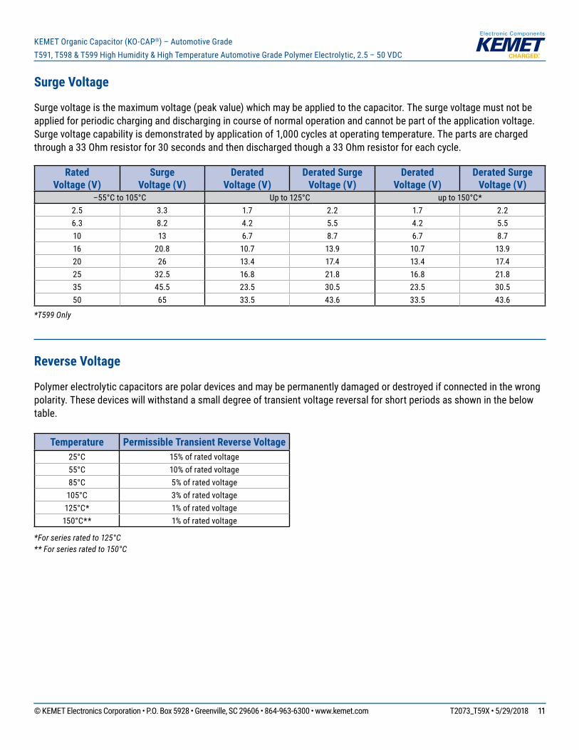
Surgevoltageisthemaximumvoltage(peakvalue)whichmaybeappliedtothecapacitor.Thesurgevoltagemustnotbeappliedforperiodiccharginganddischargingincourseofnormaloperationandcannotbepartoftheapplicationvoltage.Surgevoltagecapabilityisdemonstratedbyapplicationof1,000cyclesatoperatingtemperature.Thepartsarechargedthrougha33Ohmresistorfor30secondsandthendischargedthougha33Ohmresistorforeachcycle.
Rated Voltage (V)
Surge Voltage (V)
Derated Voltage (V)
Derated Surge Voltage (V)
Derated Voltage (V)
Derated Surge Voltage (V)
–55°C to 105°C Up to 125°C upto150°C*2.5 3.3 1.7 2.2 1.7 2.26.3 8.2 4.2 5.5 4.2 5.510 13 6.7 8.7 6.7 8.716 20.8 10.7 13.9 10.7 13.920 26 13.4 17.4 13.4 17.425 32.5 16.8 21.8 16.8 21.835 45.5 23.5 30.5 23.5 30.550 65 33.5 43.6 33.5 43.6
*T599 Only
Reverse Voltage
Polymerelectrolyticcapacitorsarepolardevicesandmaybepermanentlydamagedordestroyedifconnectedinthewrongpolarity.Thesedeviceswillwithstandasmalldegreeoftransientvoltagereversalforshortperiodsasshowninthebelowtable.
Temperature Permissible Transient Reverse Voltage25°C 15%ofratedvoltage55°C 10%ofratedvoltage85°C 5%ofratedvoltage
105°C 3%ofratedvoltage125°C* 1%ofratedvoltage150°C** 1%ofratedvoltage
*For series rated to 125°C** For series rated to 150°C
© KEMET Electronics Corporation • P.O. Box 5928 • Greenville, SC 29606 • 864-963-6300 • www.kemet.com T2073_T59X • 5/29/2018 1212
KEMET Organic Capacitor (KO-CAP®) – Automotive GradeT591, T598 & T599 High Humidity & High Temperature Automotive Grade Polymer Electrolytic, 2.5 – 50 VDC
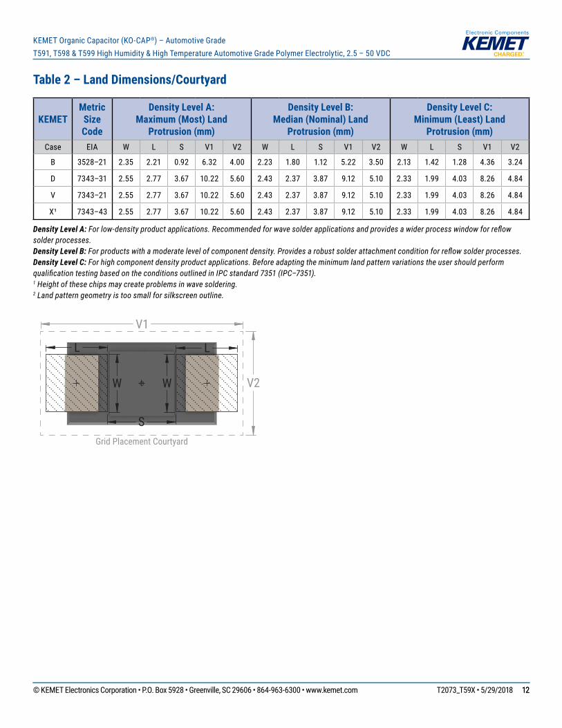
Table 2 – Land Dimensions/Courtyard
KEMET Metric Size Code
Density Level A: Maximum (Most) Land
Protrusion (mm)
Density Level B: Median (Nominal) Land
Protrusion (mm)
Density Level C: Minimum (Least) Land
Protrusion (mm)Case EIA W L S V1 V2 W L S V1 V2 W L S V1 V2
B 3528–21 2.35 2.21 0.92 6.32 4.00 2.23 1.80 1.12 5.22 3.50 2.13 1.42 1.28 4.36 3.24
D 7343–31 2.55 2.77 3.67 10.22 5.60 2.43 2.37 3.87 9.12 5.10 2.33 1.99 4.03 8.26 4.84
V 7343–21 2.55 2.77 3.67 10.22 5.60 2.43 2.37 3.87 9.12 5.10 2.33 1.99 4.03 8.26 4.84
X¹ 7343–43 2.55 2.77 3.67 10.22 5.60 2.43 2.37 3.87 9.12 5.10 2.33 1.99 4.03 8.26 4.84
Density Level A: For low-density product applications. Recommended for wave solder applications and provides a wider process window for reflow solder processes. Density Level B: For products with a moderate level of component density. Provides a robust solder attachment condition for reflow solder processes.Density Level C: For high component density product applications. Before adapting the minimum land pattern variations the user should perform qualification testing based on the conditions outlined in IPC standard 7351 (IPC–7351).1 Height of these chips may create problems in wave soldering.2 Land pattern geometry is too small for silkscreen outline.
L
S
W W
L
V1
V2
Grid Placement Courtyard
© KEMET Electronics Corporation • P.O. Box 5928 • Greenville, SC 29606 • 864-963-6300 • www.kemet.com T2073_T59X • 5/29/2018 1313
KEMET Organic Capacitor (KO-CAP®) – Automotive GradeT591, T598 & T599 High Humidity & High Temperature Automotive Grade Polymer Electrolytic, 2.5 – 50 VDC
Soldering Process
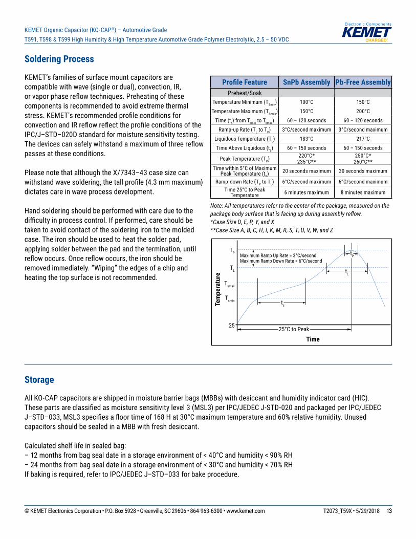
KEMET’sfamiliesofsurfacemountcapacitorsarecompatiblewithwave(singleordual),convection,IR,orvaporphasereflowtechniques.Preheatingofthesecomponentsisrecommendedtoavoidextremethermalstress.KEMET'srecommendedprofileconditionsforconvectionandIRreflowreflecttheprofileconditionsoftheIPC/J–STD–020Dstandardformoisturesensitivitytesting.Thedevicescansafelywithstandamaximumofthreereflowpassesattheseconditions.
PleasenotethatalthoughtheX/7343–43casesizecanwithstandwavesoldering,thetallprofile(4.3mmmaximum)dictatescareinwaveprocessdevelopment.
Handsolderingshouldbeperformedwithcareduetothedifficultyinprocesscontrol.Ifperformed,careshouldbetakentoavoidcontactofthesolderingirontothemoldedcase.Theironshouldbeusedtoheatthesolderpad,applyingsolderbetweenthepadandthetermination,untilreflowoccurs.Oncereflowoccurs,theironshouldberemovedimmediately.“Wiping”theedgesofachipandheatingthetopsurfaceisnotrecommended.
Profile Feature SnPb Assembly Pb-Free AssemblyPreheat/Soak
Temperature Minimum (TSmin) 100°C 150°C
Temperature Maximum (TSmax) 150°C 200°C
Time (ts)fromTsmin to Tsmax) 60–120seconds 60–120seconds
Ramp-up Rate (TL to TP) 3°C/secondmaximum 3°C/secondmaximum
LiquidousTemperature(TL) 183°C 217°C
TimeAboveLiquidous(tL) 60–150seconds 60–150seconds
Peak Temperature (TP) 220°C*235°C**
250°C*260°C**
Timewithin5°CofMaximum Peak Temperature (tP) 20secondsmaximum 30secondsmaximum
Ramp-downRate(TP to TL) 6°C/secondmaximum 6°C/secondmaximumTime 25°C to Peak
Temperature 6 minutes maximum 8 minutes maximum
Note: All temperatures refer to the center of the package, measured on the package body surface that is facing up during assembly reflow. *Case Size D, E, P, Y, and X **Case Size A, B, C, H, I, K, M, R, S, T, U, V, W, and Z
Storage
AllKO-CAPcapacitorsareshippedinmoisturebarrierbags(MBBs)withdesiccantandhumidityindicatorcard(HIC).Thesepartsareclassifiedasmoisturesensitivitylevel3(MSL3)perIPC/JEDECJ-STD-020andpackagedperIPC/JEDEC J–STD–033,MSL3specifiesafloortimeof168Hat30°Cmaximumtemperatureand60%relativehumidity.UnusedcapacitorsshouldbesealedinaMBBwithfreshdesiccant.
Calculatedshelflifeinsealedbag:–12monthsfrombagsealdateinastorageenvironmentof<40°Candhumidity<90%RH–24monthsfrombagsealdateinastorageenvironmentof<30°Candhumidity<70%RHIfbakingisrequired,refertoIPC/JEDECJ–STD–033forbakeprocedure.
Time
Tem
pera
ture
Tsmin
25
Tsmax
TL
TP Maximum Ramp Up Rate = 3°C/secondMaximum Ramp Down Rate = 6°C/second
tP
tL
ts
25°C to Peak
© KEMET Electronics Corporation • P.O. Box 5928 • Greenville, SC 29606 • 864-963-6300 • www.kemet.com T2073_T59X • 5/29/2018 1414
KEMET Organic Capacitor (KO-CAP®) – Automotive GradeT591, T598 & T599 High Humidity & High Temperature Automotive Grade Polymer Electrolytic, 2.5 – 50 VDC
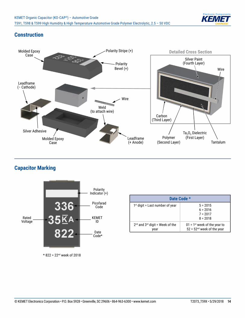
Construction
Leadframe(− Cathode)
Leadframe(+ Anode)
Wire
Molded Epoxy Case
Molded Epoxy Case
Weld(to attach wire)
Silver Adhesive
Polarity Bevel (+)
Polarity Stripe (+) Detailed Cross Section
Wire
Tantalum
Ta2O5 Dielectric(First Layer)
Carbon(Third Layer)
Silver Paint(Fourth Layer)
Polymer(Second Layer)
Capacitor Marking
* 822 = 22nd week of 2018
Polarity Indicator (+)
Rated Voltage
Picofarad Code
KEMET ID
Date Code*
Date Code *1stdigit=Lastnumberofyear 5 = 2015
6 = 20167 = 20178 = 2018
2ndand3rddigit=Weekoftheyear
01 = 1stweekoftheyearto 52 = 52ndweekoftheyear
© KEMET Electronics Corporation • P.O. Box 5928 • Greenville, SC 29606 • 864-963-6300 • www.kemet.com T2073_T59X • 5/29/2018 1515
KEMET Organic Capacitor (KO-CAP®) – Automotive GradeT591, T598 & T599 High Humidity & High Temperature Automotive Grade Polymer Electrolytic, 2.5 – 50 VDC
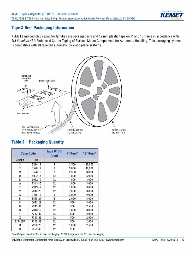
Tape & Reel Packaging Information
KEMET’smoldedchipcapacitorfamiliesarepackagedin8and12mmplastictapeon7"and13"reelsinaccordancewithEIA Standard 481:EmbossedCarrierTapingofSurfaceMountComponentsforAutomaticHandling.Thispackagingsystemiscompatiblewithalltape-fedautomaticpick-and-placesystems.
Embossment
8 mm (0.315”) or12 mm (0.472”)
Embossed carrier
Right handorientation
only
(+) (−)
Top tape thickness0.10 mm (0.004”)
maximum thickness180 mm (7.0”) or
330 mm (13.”)
Table 3 – Packaging Quantity
Case Code Tape Width (mm) 7" Reel* 13" Reel*
KEMET EIAS 3216-12 8 2,500 10,000T 3528-12 8 3,000 10,000M 3528-15 8 2,500 8,000U 6032-15 12 1,000 5,000L 6032-19 12 1,000 3,000W 7343-15 12 1,000 3,000Z 7343-17 12 1,000 3,000V 7343-20 12 1,000 3,000A 3216-18 8 2,000 9,000B 3528-21 8 2,000 8,000C 6032-28 12 500 3,000D 7343-31 12 500 2,500Q 7343-12 12 1,000 3,000Y 7343-40 12 500 2,000X 7343-43 12 500 2,000
E/T428P 7360-38 12 500 2,000H 7360-20 12 1,000 2,500O 7360-43 12 250
* No C-Spec required for 7" reel packaging. C-7280 required for 13" reel packaging.
© KEMET Electronics Corporation • P.O. Box 5928 • Greenville, SC 29606 • 864-963-6300 • www.kemet.com T2073_T59X • 5/29/2018 1616
KEMET Organic Capacitor (KO-CAP®) – Automotive GradeT591, T598 & T599 High Humidity & High Temperature Automotive Grade Polymer Electrolytic, 2.5 – 50 VDC
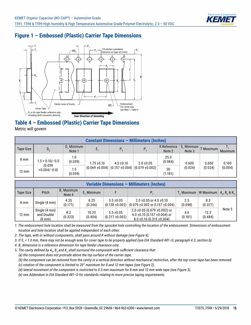
Figure 1 – Embossed (Plastic) Carrier Tape Dimensions
P0
T
F
W
Center Lines of Cavity
A0
B0
User Direction of Unreeling
Cover Tape
K0
B1 is for tape feeder reference only, including draft concentric about B0.
T2
ØD1
ØD0
B1
S1
T1
E1
E2
P1
P2
EmbossmentFor cavity size,see Note 1, Table 4
(10 pitches cumulativetolerance on tape ±0.2 mm)
Table 4 – Embossed (Plastic) Carrier Tape DimensionsMetricwillgovern
Constant Dimensions — Millimeters (Inches)
Tape Size D0 D1 Minimum
Note 1 E1 P0 P2 RReference
Note 2S1 Minimum
Note 3 T Maximum T1 Maximum
8 mm 1.5+0.10/−0.0(0.059
+0.004/−0.0)
1.0 (0.039) 1.75 ±0.10
(0.069 ±0.004)4.0 ±0.10
(0.157 ±0.004)2.0 ±0.05
(0.079 ±0.002)
25.0 (0.984) 0.600
(0.024)0.600
(0.024)0.100
(0.004)12 mm 1.5
(0.059)30
(1.181)
Variable Dimensions — Millimeters (Inches)
Tape Size Pitch B1 Maximum Note 4 E2 Minimum F P1 T2 Maximum WMaximum A0, B0 & K0
8 mm Single(4mm) 4.35 (0.171)
6.25 (0.246)
3.5 ±0.05 (0.138 ±0.002)
2.0 ±0.05 or 4.0 ±0.10(0.079 ±0.002 or 0.157 ±0.004)
2.5 (0.098)
8.3 (0.327)
Note 512 mm
Single(4mm)andDouble
(8 mm)
8.2 (0.323)
10.25 (0.404)
5.5 ±0.05 (0.217 ±0.002)
2.0 ±0.05 (0.079 ±0.002) or4.0 ±0.10 (0.157 ±0.004) or
8.0 ±0.10 (0.315 ±0.004)
4.6 (0.181)
12.3 (0.484)
1. The embossment hole location shall be measured from the sprocket hole controlling the location of the embossment. Dimensions of embossment location and hole location shall be applied independent of each other.
2. The tape, with or without components, shall pass around R without damage (see Figure 4).3. If S1 < 1.0 mm, there may not be enough area for cover tape to be properly applied (see EIA Standard 481–D, paragraph 4.3, section b).4. B1 dimension is a reference dimension for tape feeder clearance only.5. The cavity defi ned by A0, B0 and K0 shall surround the component with suffi cient clearance that: (a) the component does not protrude above the top surface of the carrier tape. (b) the component can be removed from the cavity in a vertical direction without mechanical restriction, after the top cover tape has been removed. (c) rotation of the component is limited to 20° maximum for 8 and 12 mm tapes (see Figure 2). (d) lateral movement of the component is restricted to 0.5 mm maximum for 8 mm and 12 mm wide tape (see Figure 3). (e) see Addendum in EIA Standard 481–D for standards relating to more precise taping requirements.
© KEMET Electronics Corporation • P.O. Box 5928 • Greenville, SC 29606 • 864-963-6300 • www.kemet.com T2073_T59X • 5/29/2018 1717
KEMET Organic Capacitor (KO-CAP®) – Automotive GradeT591, T598 & T599 High Humidity & High Temperature Automotive Grade Polymer Electrolytic, 2.5 – 50 VDC
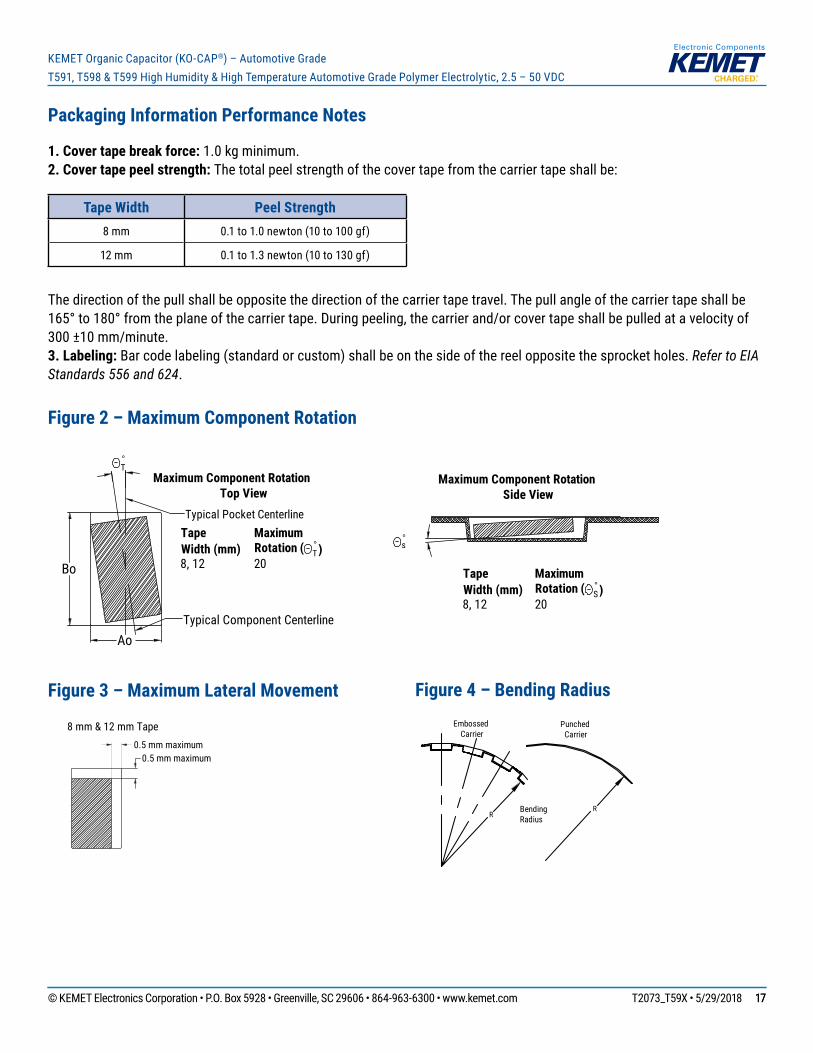
Packaging Information Performance Notes
1. Cover tape break force:1.0kgminimum.2. Cover tape peel strength: Thetotalpeelstrengthofthecovertapefromthecarriertapeshallbe:
Tape Width Peel Strength8 mm 0.1to1.0newton(10to100gf)
12 mm 0.1to1.3newton(10to130gf)
Thedirectionofthepullshallbeoppositethedirectionofthecarriertapetravel.Thepullangleofthecarriertapeshallbe165°to180°fromtheplaneofthecarriertape.Duringpeeling,thecarrierand/orcovertapeshallbepulledatavelocityof300 ±10 mm/minute.3. Labeling:Barcodelabeling(standardorcustom)shallbeonthesideofthereeloppositethesprocketholes.Refer to EIA Standards 556 and 624.
Figure 2 – Maximum Component Rotation
Ao
Bo
°T
°s
Maximum Component RotationTop View
Maximum Component RotationSide View
TapeWidth (mm)
MaximumRotation ( °
T)8, 12 20
TapeWidth (mm)
MaximumRotation (
8, 12 20 °S)
Typical Pocket Centerline
Typical Component Centerline
Figure 3 – Maximum Lateral Movement
0.5 mm maximum0.5 mm maximum
8 mm & 12 mm Tape
Figure 4 – Bending Radius
RRBending
Radius
EmbossedCarrier
PunchedCarrier
© KEMET Electronics Corporation • P.O. Box 5928 • Greenville, SC 29606 • 864-963-6300 • www.kemet.com T2073_T59X • 5/29/2018 1818
KEMET Organic Capacitor (KO-CAP®) – Automotive GradeT591, T598 & T599 High Humidity & High Temperature Automotive Grade Polymer Electrolytic, 2.5 – 50 VDC
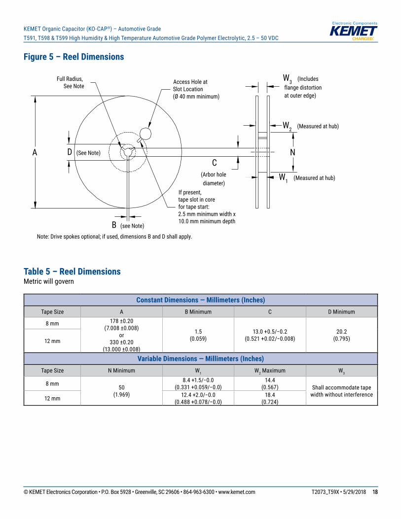
Figure 5 – Reel Dimensions
A D (See Note)
Full Radius,See Note
B (see Note)
Access Hole atSlot Location(Ø 40 mm minimum)
If present,tape slot in corefor tape start:2.5 mm minimum width x10.0 mm minimum depth
W3 (Includes flange distortion at outer edge)
W2 (Measured at hub)
W1 (Measured at hub)
C(Arbor holediameter)
Note: Drive spokes optional; if used, dimensions B and D shall apply.
N
Table 5 – Reel DimensionsMetricwillgovern
Constant Dimensions — Millimeters (Inches) Tape Size A B Minimum C DMinimum
8 mm 178 ±0.20 (7.008 ±0.008)
or330 ±0.20
(13.000 ±0.008)
1.5 (0.059)
13.0+0.5/−0.2(0.521+0.02/−0.008)
20.2 (0.795)12 mm
Variable Dimensions — Millimeters (Inches) Tape Size N Minimum W1 W2 Maximum W3
8 mm 50 (1.969)
8.4+1.5/−0.0(0.331+0.059/−0.0)
14.4 (0.567) Shallaccommodatetape
widthwithoutinterference12 mm 12.4+2.0/−0.0(0.488+0.078/−0.0)
18.4 (0.724)
© KEMET Electronics Corporation • P.O. Box 5928 • Greenville, SC 29606 • 864-963-6300 • www.kemet.com T2073_T59X • 5/29/2018 1919
KEMET Organic Capacitor (KO-CAP®) – Automotive GradeT591, T598 & T599 High Humidity & High Temperature Automotive Grade Polymer Electrolytic, 2.5 – 50 VDC
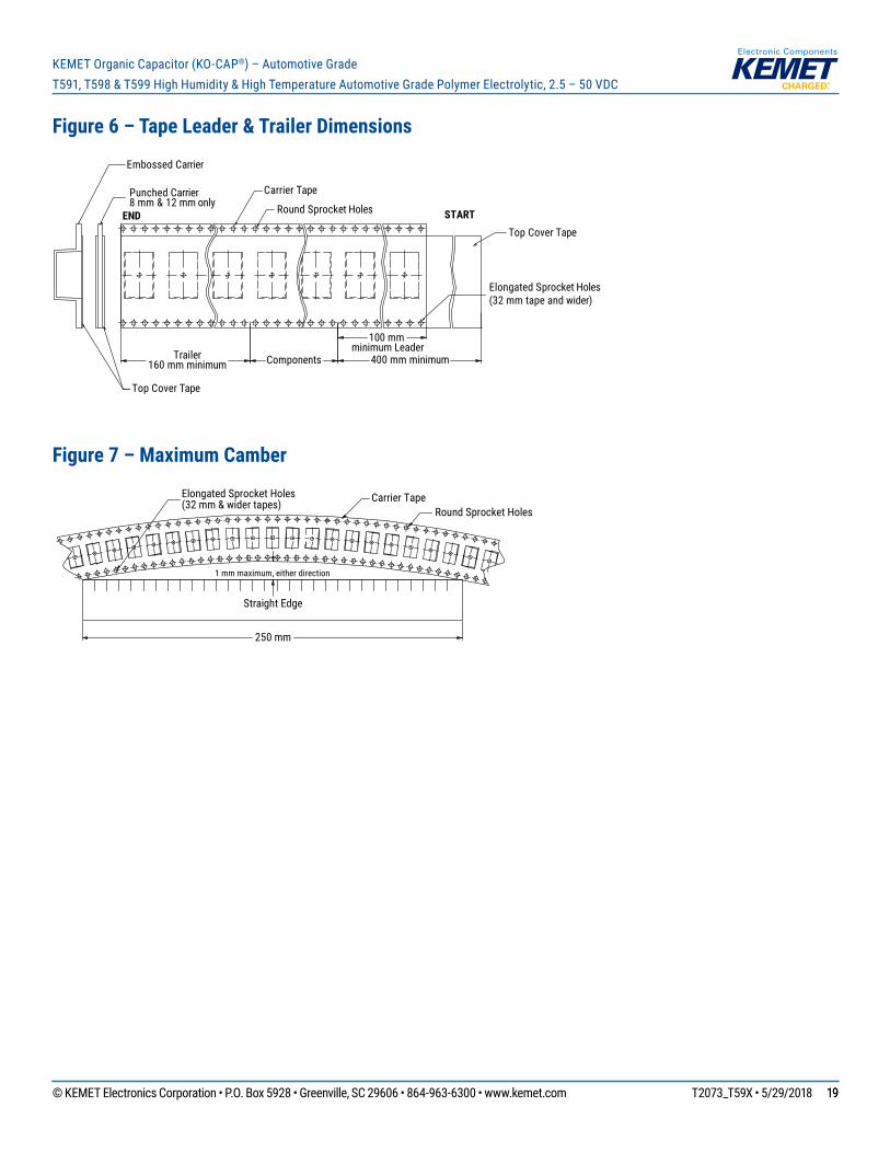
Figure 6 – Tape Leader & Trailer Dimensions
Trailer160 mm minimum
Carrier Tape
END STARTRound Sprocket Holes
Elongated Sprocket Holes(32 mm tape and wider)
Top Cover Tape
Top Cover Tape
Punched Carrier8 mm & 12 mm only
Embossed Carrier
Components
100 mm minimum Leader
400 mm minimum
Figure 7 – Maximum Camber
Carrier TapeRound Sprocket Holes
1 mm maximum, either direction
Straight Edge
250 mm
Elongated Sprocket Holes(32 mm & wider tapes)

© KEMET Electronics Corporation • P.O. Box 5928 • Greenville, SC 29606 • 864-963-6300 • www.kemet.com T2073_T59X • 5/29/2018 2020
KEMET Organic Capacitor (KO-CAP®) – Automotive GradeT591, T598 & T599 High Humidity & High Temperature Automotive Grade Polymer Electrolytic, 2.5 – 50 VDC
KEMET Electronics Corporation Sales Offi ces
Foracompletelistofourglobalsalesoffices,pleasevisitwww.kemet.com/sales.
DisclaimerAllproductspecifications,statements,informationanddata(collectively,the“Information”)inthisdatasheetaresubjecttochange.ThecustomerisresponsibleforcheckingandverifyingtheextenttowhichtheInformationcontainedinthispublicationisapplicabletoanorderatthetimetheorderisplaced.
AllInformationgivenhereinisbelievedtobeaccurateandreliable,butitispresentedwithoutguarantee,warranty,orresponsibilityofanykind,expressedorimplied.
StatementsofsuitabilityforcertainapplicationsarebasedonKEMETElectronicsCorporation’s(“KEMET”)knowledgeoftypicaloperatingconditionsforsuchapplications,butarenotintendedtoconstitute–andKEMETspecificallydisclaims–anywarrantyconcerningsuitabilityforaspecificcustomerapplicationoruse.TheInformationisintendedforuseonlybycustomerswhohavetherequisiteexperienceandcapabilitytodeterminethecorrectproductsfortheirapplication.AnytechnicaladviceinferredfromthisInformationorotherwiseprovidedbyKEMETwithreferencetotheuseofKEMET’sproductsisgivengratis,andKEMETassumesnoobligationorliabilityfortheadvicegivenorresultsobtained.
AlthoughKEMETdesignsandmanufacturesitsproductstothemoststringentqualityandsafetystandards,giventhecurrentstateoftheart,isolatedcomponentfailuresmaystilloccur.Accordingly,customerapplicationswhichrequireahighdegreeofreliabilityorsafetyshouldemploysuitabledesignsorothersafeguards(suchasinstallationofprotectivecircuitryorredundancies)inordertoensurethatthefailureofanelectricalcomponentdoesnotresultinariskofpersonalinjuryorpropertydamage.
Althoughallproduct–relatedwarnings,cautionsandnotesmustbeobserved,thecustomershouldnotassumethatallsafetymeasuresareindictedorthatothermeasuresmaynotberequired.
KEMET is a registered trademark of KEMET Electronics Corporation.