Embed Size (px)
Citation preview
Automotive Ethernet 1000Base-T1 TC9 measurement using VNA Application Note
Products:
ı R&S®ZNB4
ı R&S®ZN-Z51
ı R&S®ZV-Z135
ı R&S®ZV-Z192
This application note is a systematic guide to help test engineers configure the Vector Network Analyzer in
order to perform compliance test on Automotive Ethernet cables according to the Open Alliance TC9
standard.
Note:
Please find the most up-to-date document on our homepage
https://www.rohde-schwarz.com/appnote/GFM323
App
licat
ion
Not
e
Mah
mud
Nas
eef,
Jörn
Pfe
ifer,
And
rea
D'A
quin
o
9.20
19 –
GF
323_
2e
Table of Contents
GF323_2e Rohde & Schwarz Automotive Ethernet 1000Base-T1 TC9 measurement using VNA
2
Table of Contents
1 Introduction ......................................................................................... 3
2 Test Setup ........................................................................................... 4
3 Calibrating and Configuring the VNA for Measurement .................. 5
3.1 Characterization of the Calibration Unit .................................................................... 5
3.2 Optional de-embedding of fixture boards ................................................................. 7
3.3 Verification of VNA Calibration Accuracy ................................................................. 9
4 Measurement and Results ............................................................... 12
4.1 Measurement of Mixed-Mode S-Parameters ...........................................................12
4.2 Measurement of TDR based CIDM (Characteristic Impedance Differential Mode)
.....................................................................................................................................13
5 Reference .......................................................................................... 15
6 Ordering Information ........................................................................ 16
Introduction
GF323_2e Rohde & Schwarz Automotive Ethernet 1000Base-T1 TC9 measurement using VNA
3
1 Introduction
The evolution towards higher connectivity & electrification in the automotive industry is
faster than ever before. More and more sensors are added to vehicles as the future of
transportation moves towards higher level of automation. Reliability and quality of time
critical communications between different systems are nowadays under the spotlight,
and Ethernet cables have become the industry standard to support the network within
the car.
The Open Alliance TC9 compliance specification is regarded as a qualification
benchmark for unshielded twisted pair (UTP) cables for Automotive Ethernet [1].
This document contain electrical requirements and measurement specifications on
1000BASE-T1 channel and components link segment type A (UTP). It shall be used as a
standardized common scale for the evaluation of the RF properties for physical layer
communication channels to enable 1000BASE-T1 technology.
The focus of this application note is to describe the method of performing compliance
tests according to the TC9 specification for Ethernet cable testing. Chapter 2 describes
the test setup required to perform measurements on 1000BASE-T1 coaxial cables
using the four-port ZNB4 Vector Network Analyzer (VNA) from Rohde & Schwarz.
Chapter 3 explains the procedure of calibrating the VNA and checking the VNA
calibration accuracy. Finally, in chapter 4, measurement examples from the Open
Alliance TC9 compliance specification are shown.
Abbreviations
The following abbreviations are used in this application note for Rohde & Schwarz
products:
▪ The R&S®ZNB4 Vector Network Analyzer is referred to as ZNB
▪ The R&S®ZN-Z51 Automatic Calibration Unit is referred to as ZN-Z51
▪ The R&S®ZV-Z135 Calibration Kit is referred to as ZV-Z135
▪ Device Under Test is referred to as DUT
Test Setup
GF323_2e Rohde & Schwarz Automotive Ethernet 1000Base-T1 TC9 measurement using VNA
4
2 Test Setup
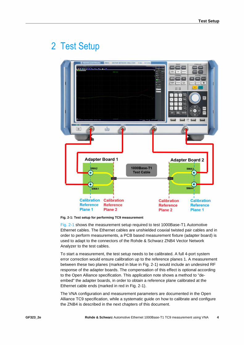
Fig. 2-1: Test setup for performing TC9 measurement
Fig. 2-1 shows the measurement setup required to test 1000Base-T1 Automotive
Ethernet cables. The Ethernet cables are unshielded coaxial twisted pair cables and in
order to perform measurements, a PCB based measurement fixture (adapter board) is
used to adapt to the connectors of the Rohde & Schwarz ZNB4 Vector Network
Analyzer to the test cables.
To start a measurement, the test setup needs to be calibrated. A full 4-port system
error correction would ensure calibration up to the reference planes 1. A measurement
between these two planes (marked in blue in Fig. 2-1) would include an undesired RF
response of the adapter boards. The compensation of this effect is optional according
to the Open Alliance specification. This application note shows a method to "de-
embed" the adapter boards, in order to obtain a reference plane calibrated at the
Ethernet cable ends (marked in red in Fig. 2-1).
The VNA configuration and measurement parameters are documented in the Open
Alliance TC9 specification, while a systematic guide on how to calibrate and configure
the ZNB4 is described in the next chapters of this document.
Calibrating and Configuring the VNA for Measurement
GF323_2e Rohde & Schwarz Automotive Ethernet 1000Base-T1 TC9 measurement using VNA
5
3 Calibrating and Configuring the VNA for
Measurement
The first step of any test performed with a VNA consists in calibrating the instrument.
As a measure of good practice, let the VNA and the calibration unit warm up about one
hour to gain stable characterization data. To obtain the required VNA calibration
accuracy a manual calibration is usually performed but automatic calibration units can
be used with the method described in the next paragraph as well. If a manual
calibration is preferred, you can ignore paragraph 3.1.
The VNA needs to be configured to the settings defined in table: 4.2-2 of the Open
Alliance TC9 test specification [1].
3.1 Characterization of the Calibration Unit
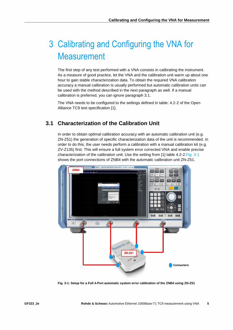
In order to obtain optimal calibration accuracy with an automatic calibration unit (e.g.
ZN-Z51) the generation of specific characterization data of the unit is recommended. In
order to do this, the user needs perform a calibration with a manual calibration kit (e.g.
ZV-Z135) first. This will ensure a full system error corrected VNA and enable precise
characterization of the calibration unit. Use the setting from [1] table 4.2-2.Fig. 3-1
shows the port connections of ZNB4 with the automatic calibration unit ZN-Z51.
Fig. 3-1: Setup for a Full 4-Port automatic system error calibration of the ZNB4 using ZN-Z51
Calibrating and Configuring the VNA for Measurement
GF323_2e Rohde & Schwarz Automotive Ethernet 1000Base-T1 TC9 measurement using VNA
6
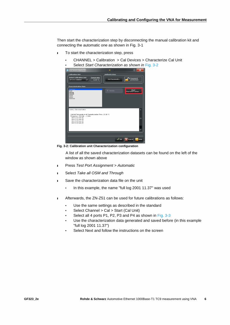
Then start the characterization step by disconnecting the manual calibration kit and
connecting the automatic one as shown in Fig. 3-1
ı To start the characterization step, press
▪ CHANNEL > Calibration > Cal Devices > Characterize Cal Unit
▪ Select Start Characterization as shown in Fig. 3-2
Fig. 3-2: Calibration unit Characterization configuration
A list of all the saved characterization datasets can be found on the left of the
window as shown above
ı Press Test Port Assignment > Automatic
ı Select Take all OSM and Through
ı Save the characterization data file on the unit
▪ In this example, the name "full log 2001 11.37" was used
ı Afterwards, the ZN-Z51 can be used for future calibrations as follows:
▪ Use the same settings as described in the standard
▪ Select Channel > Cal > Start (Cal Unit)
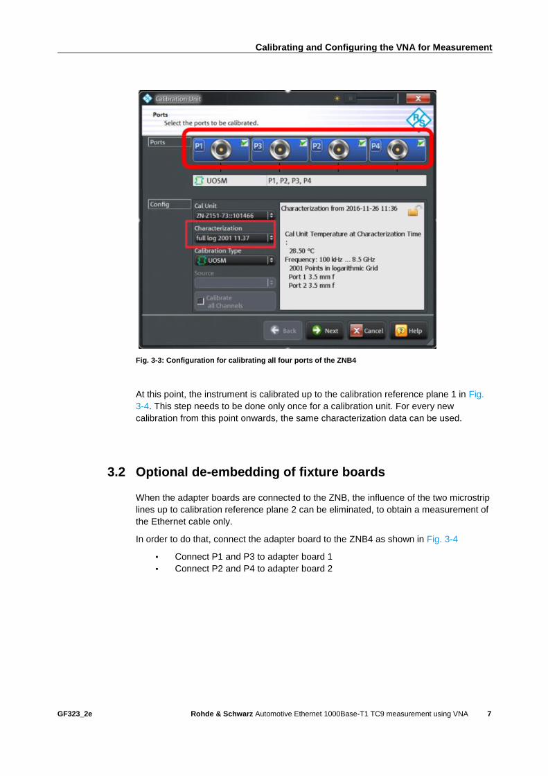
▪ Select all 4 ports P1, P2, P3 and P4 as shown in Fig. 3-3
▪ Use the characterization data generated and saved before (in this example
"full log 2001 11.37")
▪ Select Next and follow the instructions on the screen
Calibrating and Configuring the VNA for Measurement
GF323_2e Rohde & Schwarz Automotive Ethernet 1000Base-T1 TC9 measurement using VNA
7
Fig. 3-3: Configuration for calibrating all four ports of the ZNB4
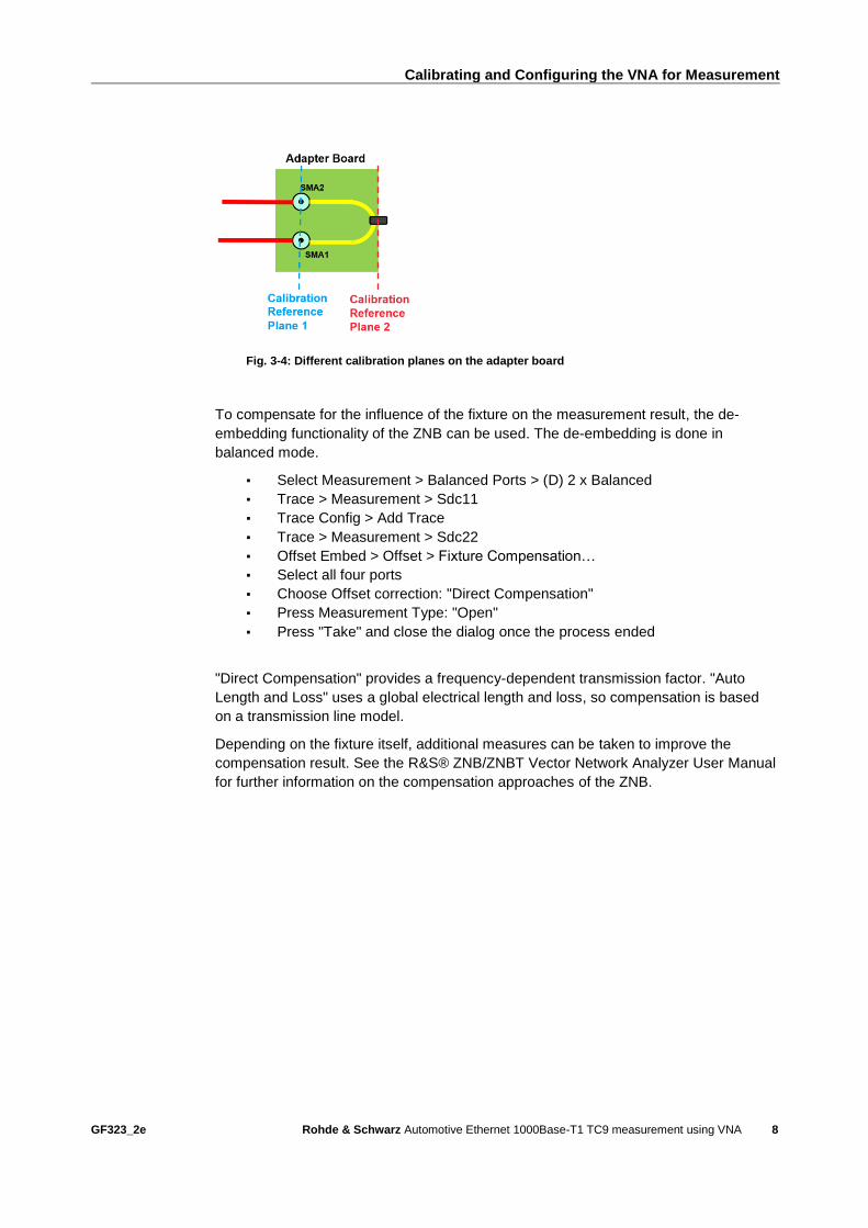
At this point, the instrument is calibrated up to the calibration reference plane 1 in Fig.
3-4. This step needs to be done only once for a calibration unit. For every new
calibration from this point onwards, the same characterization data can be used.
3.2 Optional de-embedding of fixture boards
When the adapter boards are connected to the ZNB, the influence of the two microstrip
lines up to calibration reference plane 2 can be eliminated, to obtain a measurement of
the Ethernet cable only.
In order to do that, connect the adapter board to the ZNB4 as shown in Fig. 3-4
▪ Connect P1 and P3 to adapter board 1
▪ Connect P2 and P4 to adapter board 2
Calibrating and Configuring the VNA for Measurement
GF323_2e Rohde & Schwarz Automotive Ethernet 1000Base-T1 TC9 measurement using VNA
8
Fig. 3-4: Different calibration planes on the adapter board
To compensate for the influence of the fixture on the measurement result, the de-
embedding functionality of the ZNB can be used. The de-embedding is done in
balanced mode.
▪ Select Measurement > Balanced Ports > (D) 2 x Balanced
▪ Trace > Measurement > Sdc11
▪ Trace Config > Add Trace
▪ Trace > Measurement > Sdc22
▪ Offset Embed > Offset > Fixture Compensation…
▪ Select all four ports
▪ Choose Offset correction: "Direct Compensation"
▪ Press Measurement Type: "Open"
▪ Press "Take" and close the dialog once the process ended
"Direct Compensation" provides a frequency-dependent transmission factor. "Auto
Length and Loss" uses a global electrical length and loss, so compensation is based
on a transmission line model.
Depending on the fixture itself, additional measures can be taken to improve the
compensation result. See the R&S® ZNB/ZNBT Vector Network Analyzer User Manual
for further information on the compensation approaches of the ZNB.
Calibrating and Configuring the VNA for Measurement
GF323_2e Rohde & Schwarz Automotive Ethernet 1000Base-T1 TC9 measurement using VNA
9
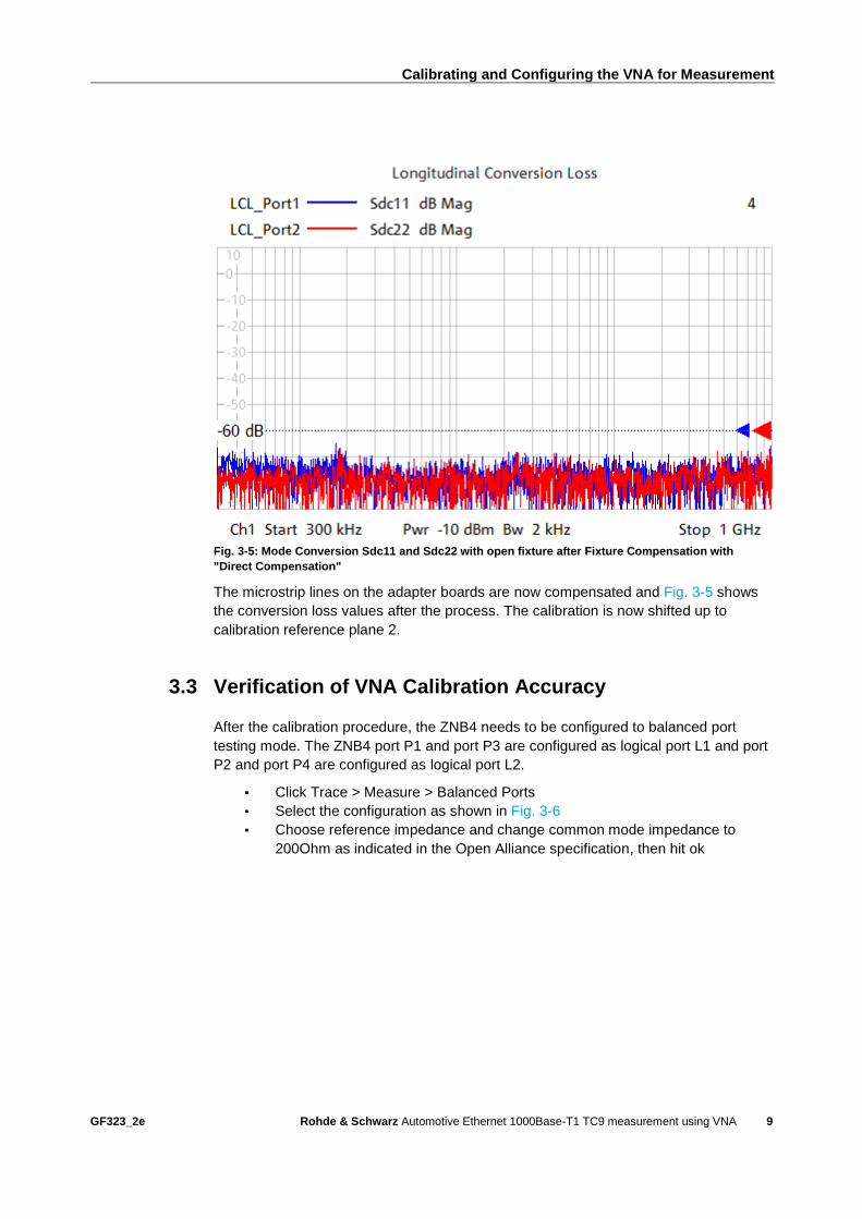
Fig. 3-5: Mode Conversion Sdc11 and Sdc22 with open fixture after Fixture Compensation with
"Direct Compensation"
The microstrip lines on the adapter boards are now compensated and Fig. 3-5 shows
the conversion loss values after the process. The calibration is now shifted up to
calibration reference plane 2.
3.3 Verification of VNA Calibration Accuracy
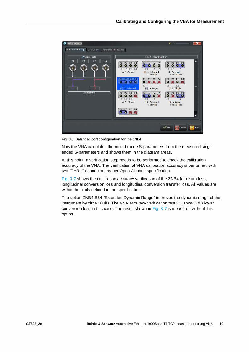
After the calibration procedure, the ZNB4 needs to be configured to balanced port
testing mode. The ZNB4 port P1 and port P3 are configured as logical port L1 and port
P2 and port P4 are configured as logical port L2.
▪ Click Trace > Measure > Balanced Ports
▪ Select the configuration as shown in Fig. 3-6
▪ Choose reference impedance and change common mode impedance to
200Ohm as indicated in the Open Alliance specification, then hit ok
Calibrating and Configuring the VNA for Measurement
GF323_2e Rohde & Schwarz Automotive Ethernet 1000Base-T1 TC9 measurement using VNA
10
Fig. 3-6: Balanced port configuration for the ZNB4
Now the VNA calculates the mixed-mode S-parameters from the measured single-
ended S-parameters and shows them in the diagram areas.
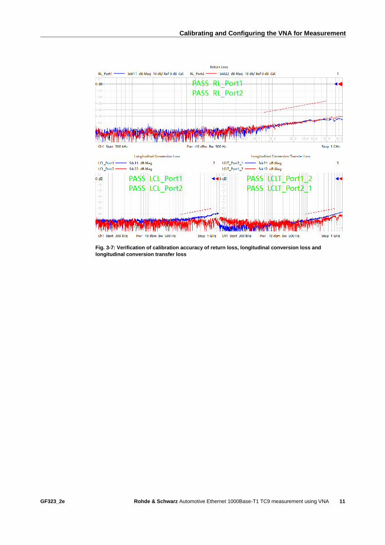
At this point, a verification step needs to be performed to check the calibration
accuracy of the VNA. The verification of VNA calibration accuracy is performed with
two "THRU" connectors as per Open Alliance specification.
Fig. 3-7 shows the calibration accuracy verification of the ZNB4 for return loss,
longitudinal conversion loss and longitudinal conversion transfer loss. All values are
within the limits defined in the specification.
The option ZNB4-B54 "Extended Dynamic Range" improves the dynamic range of the
instrument by circa 10 dB. The VNA accuracy verification test will show 5 dB lower
conversion loss in this case. The result shown in Fig. 3-7 is measured without this
option.
Calibrating and Configuring the VNA for Measurement
GF323_2e Rohde & Schwarz Automotive Ethernet 1000Base-T1 TC9 measurement using VNA
11
Fig. 3-7: Verification of calibration accuracy of return loss, longitudinal conversion loss and
longitudinal conversion transfer loss
Measurement and Results
GF323_2e Rohde & Schwarz Automotive Ethernet 1000Base-T1 TC9 measurement using VNA
12
4 Measurement and Results
As an example of measurement, the return loss and insertion loss of an Ethernet cable
are taken into consideration. The measurement of CIDM (Characteristic Impedance
Differential Mode) is also explained in the following paragraphs. The fixtures used in
the following example meet the requirements of [1].
4.1 Measurement of Mixed-Mode S-Parameters
If all the steps in the previous chapters have been correctly performed, the setup is
fully calibrated and configured to measure as described in Open Alliance
specifications.
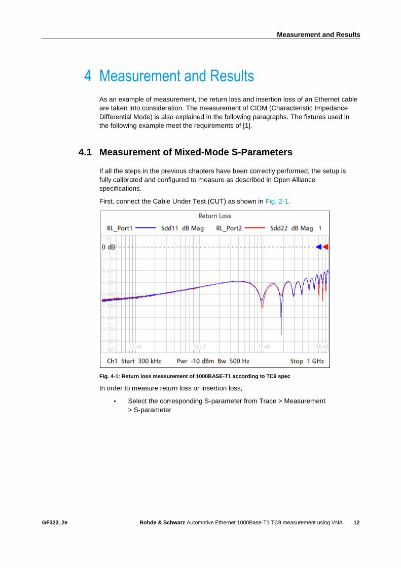
First, connect the Cable Under Test (CUT) as shown in Fig. 2-1.
Fig. 4-1: Return loss measurement of 1000BASE-T1 according to TC9 spec
In order to measure return loss or insertion loss,
▪ Select the corresponding S-parameter from Trace > Measurement
> S-parameter
Measurement and Results
GF323_2e Rohde & Schwarz Automotive Ethernet 1000Base-T1 TC9 measurement using VNA
13
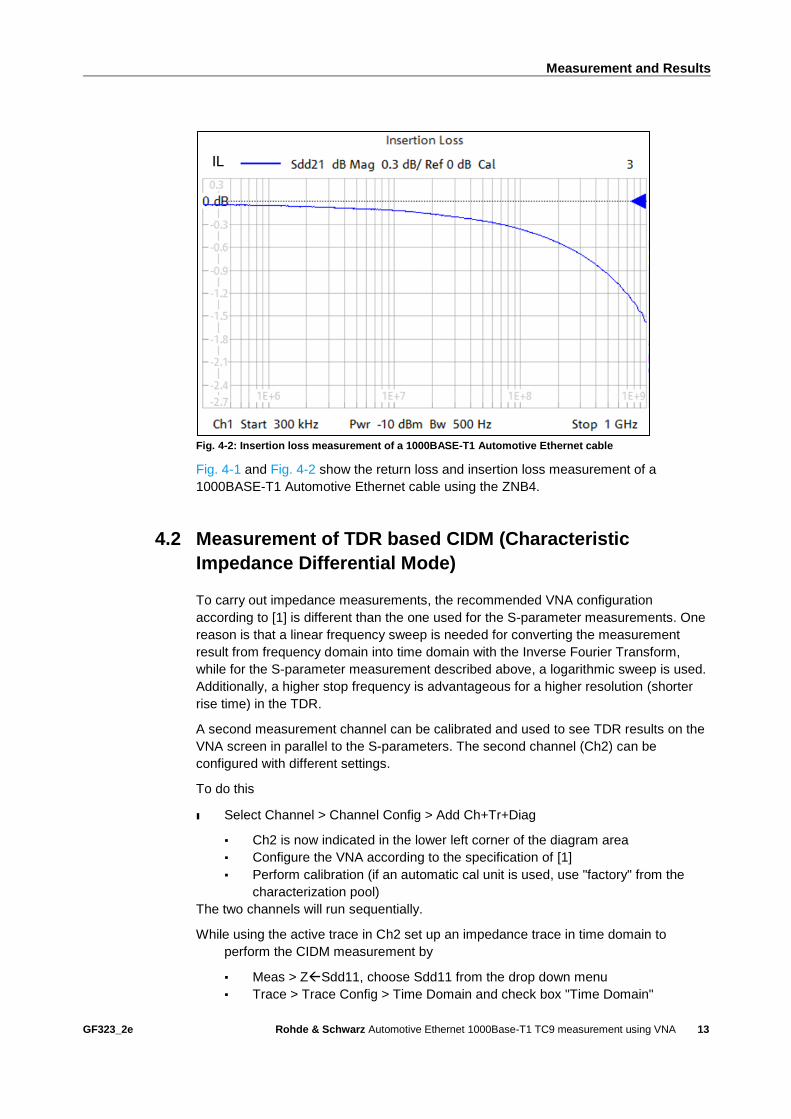
Fig. 4-2: Insertion loss measurement of a 1000BASE-T1 Automotive Ethernet cable
Fig. 4-1 and Fig. 4-2 show the return loss and insertion loss measurement of a
1000BASE-T1 Automotive Ethernet cable using the ZNB4.
4.2 Measurement of TDR based CIDM (Characteristic
Impedance Differential Mode)
To carry out impedance measurements, the recommended VNA configuration
according to [1] is different than the one used for the S-parameter measurements. One
reason is that a linear frequency sweep is needed for converting the measurement
result from frequency domain into time domain with the Inverse Fourier Transform,
while for the S-parameter measurement described above, a logarithmic sweep is used.
Additionally, a higher stop frequency is advantageous for a higher resolution (shorter
rise time) in the TDR.
A second measurement channel can be calibrated and used to see TDR results on the
VNA screen in parallel to the S-parameters. The second channel (Ch2) can be
configured with different settings.
To do this
ı Select Channel > Channel Config > Add Ch+Tr+Diag
▪ Ch2 is now indicated in the lower left corner of the diagram area
▪ Configure the VNA according to the specification of [1]
▪ Perform calibration (if an automatic cal unit is used, use "factory" from the
characterization pool)
The two channels will run sequentially.
While using the active trace in Ch2 set up an impedance trace in time domain to
perform the CIDM measurement by
▪ Meas > ZSdd11, choose Sdd11 from the drop down menu
▪ Trace > Trace Config > Time Domain and check box "Time Domain"
Measurement and Results
GF323_2e Rohde & Schwarz Automotive Ethernet 1000Base-T1 TC9 measurement using VNA
14
▪ Choose Type "low pass step" from the drop down menu
▪ Press "Low Pass Settings…" and check box DC Value "Continuous
extrapolation"
▪ Stimulus > Stop to adapt the stop time to the DUT. Electrically long DUTs
need a longer analysis time
Fig. 4-3: Typical CIDM measurement based on time domain measurement of an automotive
Ethernet cable
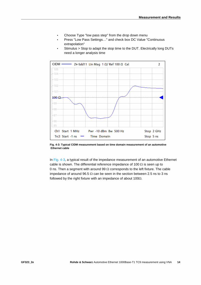
In Fig. 4-3, a typical result of the impedance measurement of an automotive Ethernet
cable is shown. The differential reference impedance of 100 is seen up to
0 ns. Then a segment with around 99 corresponds to the left fixture. The cable
impedance of around 96.5 can be seen in the section between 2.5 ns to 3 ns
followed by the right fixture with an impedance of about 100.
Reference
GF323_2e Rohde & Schwarz Automotive Ethernet 1000Base-T1 TC9 measurement using VNA
15
5 Reference
[1] Link Segment Type A (UTP) 1000BASE-T1 Ethernet Channel and Components
Specification - TC9, Open Alliance, Weblink: http://www.opensig.org/tech-
committees/tc9/
Ordering Information
GF323_2e Rohde & Schwarz Automotive Ethernet 1000Base-T1 TC9 measurement using VNA
16
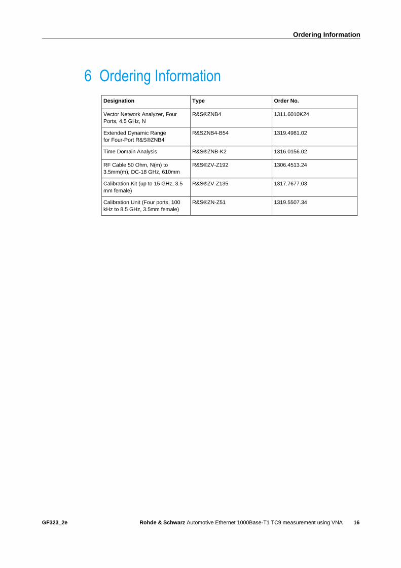
6 Ordering Information
Designation Type Order No.
Vector Network Analyzer, Four
Ports, 4.5 GHz, N
R&S®ZNB4 1311.6010K24
Extended Dynamic Range
for Four-Port R&S®ZNB4
R&SZNB4-B54 1319.4981.02
Time Domain Analysis R&S®ZNB-K2 1316.0156.02
RF Cable 50 Ohm, N(m) to
3.5mm(m), DC-18 GHz, 610mm
R&S®ZV-Z192 1306.4513.24
Calibration Kit (up to 15 GHz, 3.5
mm female)
R&S®ZV-Z135 1317.7677.03
Calibration Unit (Four ports, 100
kHz to 8.5 GHz, 3.5mm female)
R&S®ZN-Z51 1319.5507.34
Rohde & Schwarz
The Rohde & Schwarz electronics group offers
innovative solutions in the following business fields:
test and measurement, broadcast and media, secure
communications, cybersecurity, radiomonitoring and
radiolocation. Founded more than 80 years ago, this
independent company has an extensive sales and
service network and is present in more than 70
countries.
The electronics group is among the world market
leaders in its established business fields. The
company is headquartered in Munich, Germany. It
also has regional headquarters in Singapore and
Columbia, Maryland, USA, to manage its operations
in these regions.
Regional contact
Europe, Africa, Middle East +49 89 4129 12345 [email protected] North America 1 888 TEST RSA (1 888 837 87 72) [email protected] Latin America +1 410 910 79 88 [email protected] Asia Pacific +65 65 13 04 88 [email protected]
China +86 800 810 82 28 |+86 400 650 58 96 [email protected]
Sustainable product design
ı Environmental compatibility and eco-footprint
ı Energy efficiency and low emissions
ı Longevity and optimized total cost of ownership
This application note and the supplied programs
may only be used subject to the conditions of use
set forth in the download area of the Rohde &
Schwarz website.
Version GF323_2e | R&S®Automotive Ethernet 1000Base-T1 TC9
measurement using VNA
R&S® is a registered trademark of Rohde & Schwarz GmbH & Co.
KG; Trade names are trademarks of the owners.
Rohde & Schwarz GmbH & Co. KG
Mühldorfstraße 15 | 81671 Munich, Germany
Phone + 49 89 4129 - 0 | Fax + 49 89 4129 – 13777
www.rohde-schwarz.com
PA
D-T
-M: 3573.7
380.0
2/0
3.0
0/E
N

Wl,ı\.~~rııl'I'S.....i ı\]J~~](https://img.pdfslide.us/doc/110x75/6063d0332f94ab26ab40ccdd/near-east-university-faculty-of-tableofcontents-cliwlrlisi.jpg)


![µoıµ„o˚’ U „¡’ }’ „‰µ]ı˚ ı v] }’ ˚vı„˚ KªÙ˚ݪ°ªç ... · 2019. 2. 27. · µoıµ„o˚’ U „¡’ }’ ˙ „‰µ]ı˚ ı v] }’ ˚vı„˚](https://img.pdfslide.us/doc/110x75/6148f9779241b00fbd674270/oaoa-u-aa-a-aa-v-a-va-k.jpg)