Embed Size (px)
Citation preview
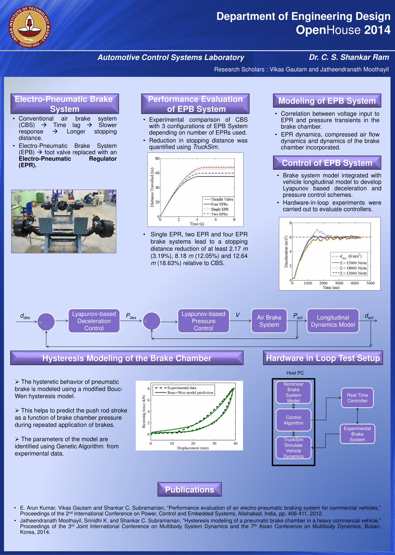
• Experimental comparison of CBSwith 3 configurations of EPB Systemdepending on number of EPRs used.
• Reduction in stopping distance wasquantified using TruckSim.
• Single EPR, two EPR and four EPR
brake systems lead to a stopping
distance reduction of at least 2.17 m
(3.19%), 8.18 m (12.05%) and 12.64
m (18.63%) relative to CBS.
.
• Conventional air brake system(CBS) Time lag Slowerresponse Longer stoppingdistance.
• Electro-Pneumatic Brake System(EPB) foot valve replaced with anElectro-Pneumatic Regulator(EPR).
Department of Engineering Design
OpenHouse 2014
Electro-Pneumatic Brake
System
Performance Evaluation
of EPB System
Hysteresis Modeling of the Brake Chamber
Publications
Automotive Control Systems Laboratory Dr. C. S. Shankar Ram
ddesLyapunov-based
Deceleration
Control
Lyapunov-based
Pressure
Control
Air Brake
System
Longitudinal
Dynamics Model+-
+-
Pdes dactPactV
• Correlation between voltage input toEPR and pressure transients in thebrake chamber.
• EPR dynamics, compressed air flowdynamics and dynamics of the brakechamber incorporated.
Modeling of EPB System
• E. Arun Kumar, Vikas Gautam and Shankar C. Subramanian, “Performance evaluation of an electro-pneumatic braking system for commercial vehicles,”Proceedings of the 2nd International Conference on Power, Control and Embedded Systems, Allahabad, India, pp. 406-411, 2012.
• Jatheendranath Moothayil, Srinidhi K. and Shankar C. Subramanian, “Hysteresis modeling of a pneumatic brake chamber in a heavy commercial vehicle,”Proceedings of the 3rd Joint International Conference on Multibody System Dynamics and the 7th Asian Conference on Multibody Dynamics, Busan,Korea, 2014.
Control of EPB System
• Brake system model integrated withvehicle longitudinal model to developLyapunov based deceleration andpressure control schemes.
• Hardware-in-loop experiments werecarried out to evaluate controllers.
The hysteretic behavior of pneumatic
brake is modeled using a modified Bouc-
Wen hysteresis model.
This helps to predict the push rod stroke
as a function of brake chamber pressure
during repeated application of brakes.
The parameters of the model are
identified using Genetic Algorithm from
experimental data.
Real Time Controller
ExperimentalBrake
SystemTruckSimSimulate Vehicle
Dynamics
NonlinearBrake
SystemModel
Host PC
Control Algorithm
Hardware in Loop Test Setup
Research Scholars : Vikas Gautam and Jatheendranath Moothayil
• Vignesh Rajaram and Shankar C. Subramanian, “A Model Based Collision Avoidance Algorithm for Heavy Commercial Vehicles,” Proceedings of the 2014
American Control Conference, Portland, Oregon, USA, pp. 3213-3218, June 2014.
• Vignesh Rajaram and Shankar C. Subramanian, “A model based rear end collision avoidance algorithm for heavy commercial road vehicles,” In Press, Proceedings of the Institution of Mechanical Engineers, Part D: Journal of Automobile Engineering.
Department of Engineering Design
OpenHouse 2014
Active Safety Systems Research Areas
Automotive Control Systems LaboratoryDr. C. S. Shankar Ram
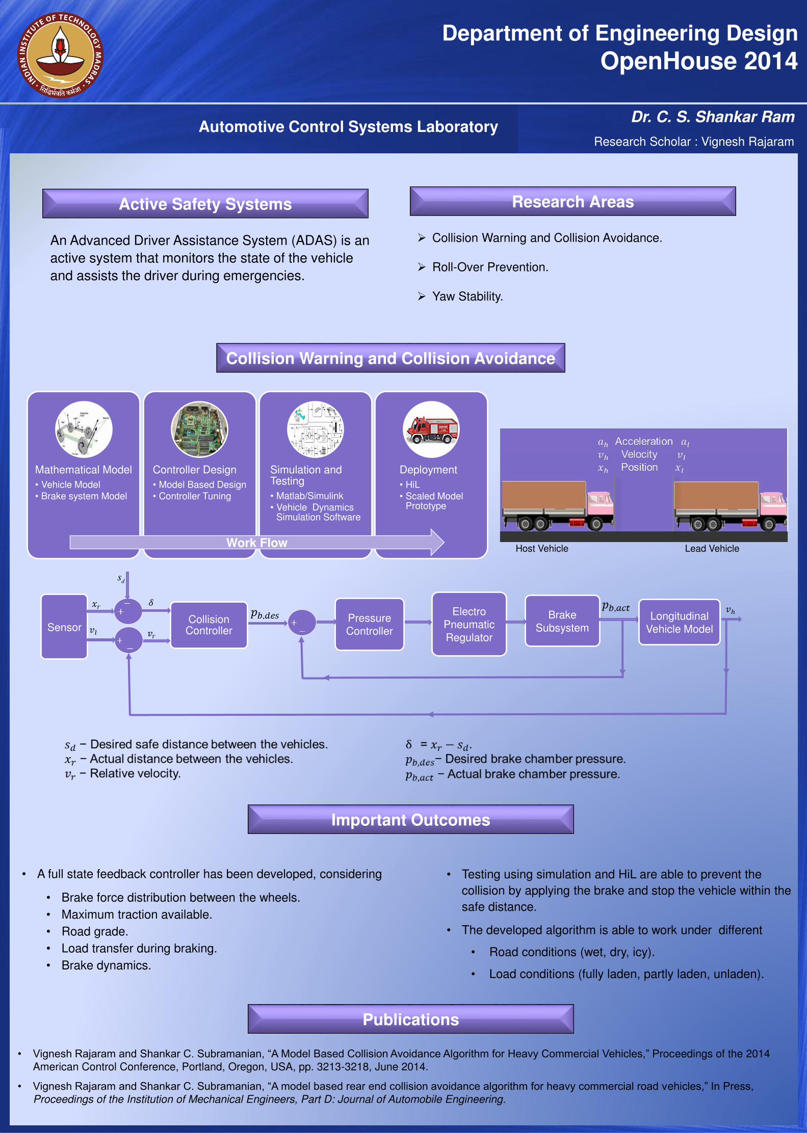
Collision Warning and Collision Avoidance.
Roll-Over Prevention.
Yaw Stability.
Collision Warning and Collision Avoidance
An Advanced Driver Assistance System (ADAS) is an
active system that monitors the state of the vehicle
and assists the driver during emergencies.
Important Outcomes
Mathematical Model
• Vehicle Model
• Brake system Model
Controller Design
• Model Based Design
• Controller Tuning
Simulation and Testing
• Matlab/Simulink
• Vehicle Dynamics Simulation Software
Deployment
• HiL
• Scaled Model Prototype
Work Flow
Collision Controller
Electro
Pneumatic
Regulator
Brake
SubsystemPressure
ControllerSensorLongitudinal
Vehicle Model
Publications
• A full state feedback controller has been developed, considering
• Brake force distribution between the wheels.
• Maximum traction available.
• Road grade.
• Load transfer during braking.
• Brake dynamics.
• Testing using simulation and HiL are able to prevent the
collision by applying the brake and stop the vehicle within the
safe distance.
• The developed algorithm is able to work under different
• Road conditions (wet, dry, icy).
• Load conditions (fully laden, partly laden, unladen).
Host Vehicle Lead Vehicle
Research Scholar : Vignesh Rajaram
ds
Department of Engineering Design
OpenHouse 2014
Automotive Control Systems Laboratory Dr. C. S. Shankar Ram
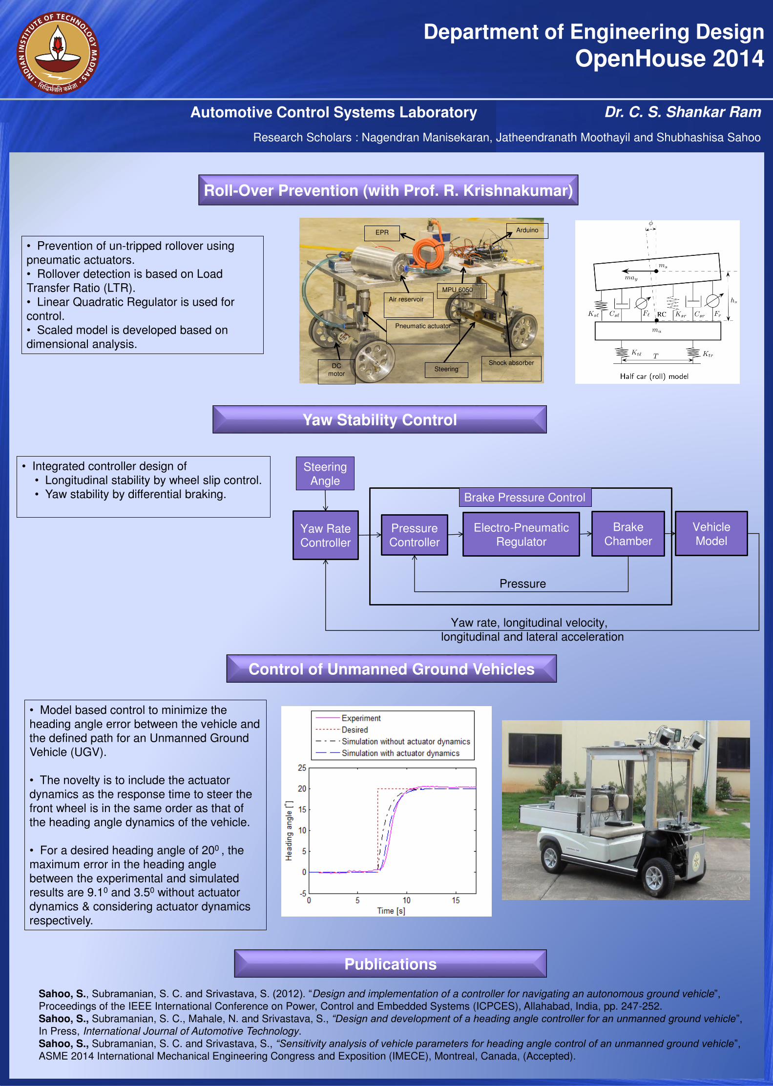
Roll-Over Prevention (with Prof. R. Krishnakumar)
SteeringShock absorber
Air reservoir
EPR
MPU 6050
Arduino
Pneumatic actuator
DC
motor
• Prevention of un-tripped rollover using
pneumatic actuators.
• Rollover detection is based on Load
Transfer Ratio (LTR).
• Linear Quadratic Regulator is used for
control.
• Scaled model is developed based on
dimensional analysis.
Yaw Stability Control
Yaw Rate
Controller
Pressure
Controller
Electro-Pneumatic
Regulator
Brake
Chamber
Vehicle
Model
Steering
Angle
Pressure
Yaw rate, longitudinal velocity,
longitudinal and lateral acceleration
Brake Pressure Control
• Integrated controller design of
• Longitudinal stability by wheel slip control.
• Yaw stability by differential braking.
Control of Unmanned Ground Vehicles
• Model based control to minimize the
heading angle error between the vehicle and
the defined path for an Unmanned Ground
Vehicle (UGV).
• The novelty is to include the actuator
dynamics as the response time to steer the
front wheel is in the same order as that of
the heading angle dynamics of the vehicle.
• For a desired heading angle of 200 , the
maximum error in the heading angle
between the experimental and simulated
results are 9.10 and 3.50 without actuator
dynamics & considering actuator dynamics
respectively.
Sahoo, S., Subramanian, S. C. and Srivastava, S. (2012). “Design and implementation of a controller for navigating an autonomous ground vehicle”, Proceedings of the IEEE International Conference on Power, Control and Embedded Systems (ICPCES), Allahabad, India, pp. 247-252.
Sahoo, S., Subramanian, S. C., Mahale, N. and Srivastava, S., “Design and development of a heading angle controller for an unmanned ground vehicle”, In Press, International Journal of Automotive Technology.
Sahoo, S., Subramanian, S. C. and Srivastava, S., “Sensitivity analysis of vehicle parameters for heading angle control of an unmanned ground vehicle”, ASME 2014 International Mechanical Engineering Congress and Exposition (IMECE), Montreal, Canada, (Accepted).
Publications
Research Scholars : Nagendran Manisekaran, Jatheendranath Moothayil and Shubhashisa Sahoo
• C S Nandakumar and Shankar C. Subramanian, “Design and analysis of a series hybrid electric vehicle for Indian conditions,” Proceedings of the ASME 2012 International Mechanical Engineering Congress & Exposition (IMECE2012), November 9-15, 2012, Houston, Texas, USA.
Department of Engineering Design
Open House 2014
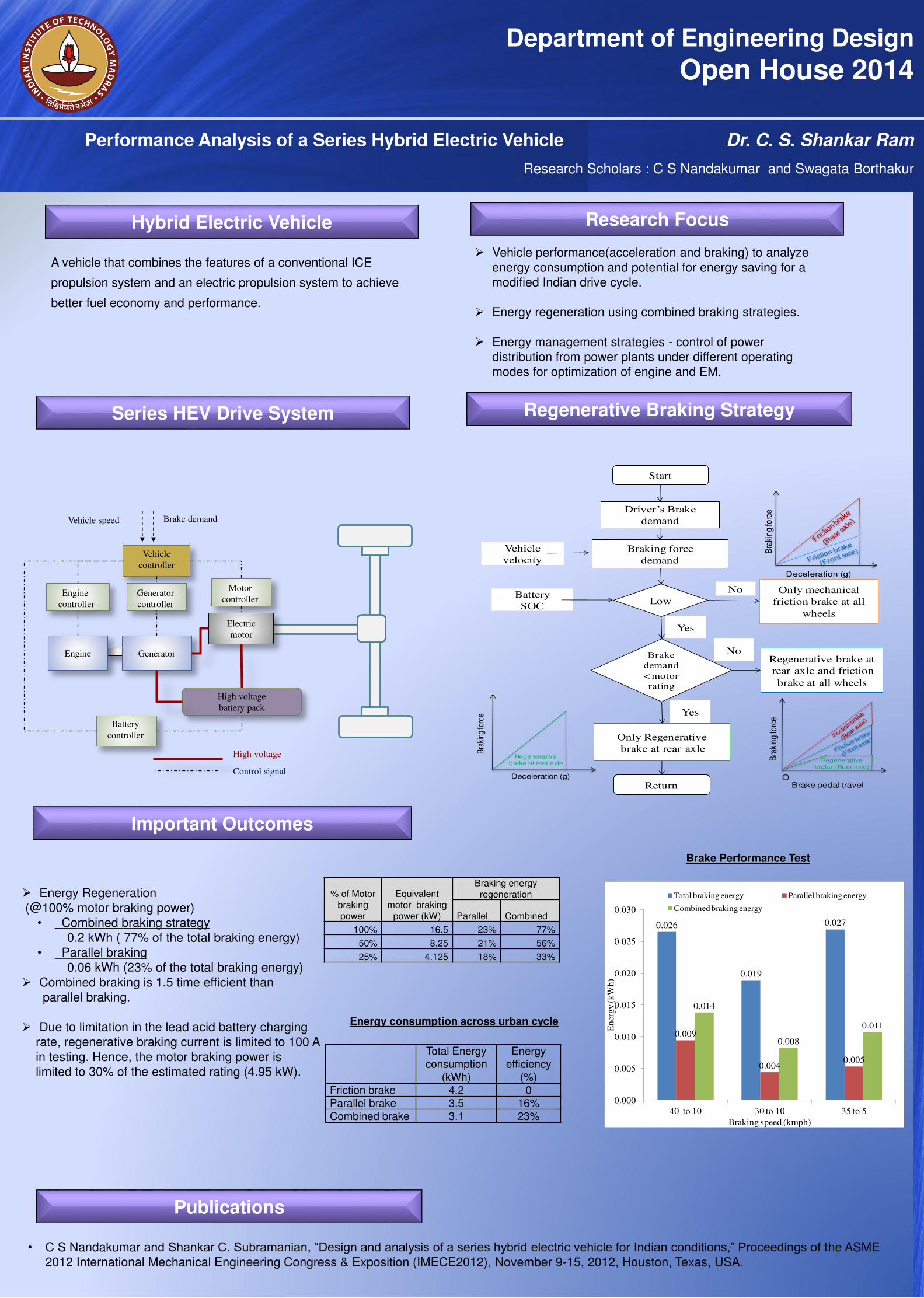
Hybrid Electric Vehicle Research Focus
Performance Analysis of a Series Hybrid Electric Vehicle Dr. C. S. Shankar Ram
Vehicle performance(acceleration and braking) to analyze energy consumption and potential for energy saving for a modified Indian drive cycle.
Energy regeneration using combined braking strategies.
Energy management strategies - control of power distribution from power plants under different operating modes for optimization of engine and EM.
Series HEV Drive System
A vehicle that combines the features of a conventional ICE
propulsion system and an electric propulsion system to achieve
better fuel economy and performance.
Important Outcomes
Publications
Vehicle
controller
Motor
controller
Electric
motor
Engine Generator
High voltage
battery pack
Generator
controller
Engine
controller
High voltage
Control signal
Brake demand
Battery
controller
Vehicle speed
Driver’s Brake demand
Start
Low
Braking force
demand
Battery
SOC
Vehicle
velocity
Yes
No Only mechanical
friction brake at all
wheels
Brake
demand
< motor
rating
Regenerative brake at
rear axle and friction
brake at all wheels
No
Only Regenerative
brake at rear axle
Yes
Return
Deceleration (g)
Bra
kin
g fo
rce
Regenerative brake (Rear axle)
Bra
kin
g fo
rce
Brake pedal travel O
Regenerativebrake at rear axle
Deceleration (g)
Bra
king
forc
e
Regenerative Braking Strategy
Energy Regeneration (@100% motor braking power)
• Combined braking strategy0.2 kWh ( 77% of the total braking energy)
• Parallel braking0.06 kWh (23% of the total braking energy)
Combined braking is 1.5 time efficient than parallel braking.
Due to limitation in the lead acid battery chargingrate, regenerative braking current is limited to 100 Ain testing. Hence, the motor braking power islimited to 30% of the estimated rating (4.95 kW).
Total Energy consumption
(kWh)
Energy efficiency
(%)Friction brake 4.2 0Parallel brake 3.5 16%Combined brake 3.1 23%
Brake Performance Test
0.026
0.019
0.027
0.009
0.0040.005
0.014
0.008
0.011
0.000
0.005
0.010
0.015
0.020
0.025
0.030
40 to 10 30 to 10 35 to 5
En
erg
y (k
Wh
)
Braking speed (kmph)
Total braking energy Parallel braking energy
Combined braking energy
% of Motor braking power
Equivalent motor braking
power (kW)
Braking energy regeneration
Parallel Combined
100% 16.5 23% 77%
50% 8.25 21% 56%
25% 4.125 18% 33%
Energy consumption across urban cycle
Research Scholars : C S Nandakumar and Swagata Borthakur