Embed Size (px)
Citation preview

Technical Support
AutomationDirect
We strive to make our manuals the best in the industry. We rely on your feedback to let us know if we are reaching our goal. If you cannot find the solution to your particular application, or, if for any reason you need additional technical assistance, please call us at 770-844-4200.
Our technical support group is glad to work with you in answering your questions. They are available weekdays from 9:00am to 6:00pm Eastern Standard Time. We also encourage you to visit our website where you can find technical and non-technical information about our products and our company. Visit us at www.automationdirect.com for additional information and FAQ’s on our process controllers.
1/16 DIN Series
General Safety Information
Electrical Hazards and Warnings Prior to connecting the controller, read the user’s manual for proper connection and operating information. Follow National Electrical Code (NEC) safety requirements when wiring and connecting a power source and sensors or other devices to the controller. Failure to do so could result in injury, death or damage to equipment and property. Make sure the proper input voltage is applied to the controller. Improper voltage will result in damage to the unit. Use caution when removing the controller from its case, there may be live voltage present at the terminals. This should only be done by a qualified technician. All terminal screws must be tightened securely. Terminal screws not properly secured can cause an electrical short that may damage property, equipment or cause injury or death. Terminal screws improperly secured may fall into equipment causing possible damage to property or equipment. This instrument is not intended for use in life safety applications.
Important: For applications where physical injury or equipment damage might occur in the event our product fails, we recommend the installation of independent safety equipment with its own independent sensor that will shut down the process.
Operator’s Manual
PM24
Microprocessor - Based Process/Temperature
Limit Controller
PM24 Operator’s Manual Made In USA
1
Important: Firmware version of controller must match the version indicated on the bottom front cover of this manual.
Manual Rev. 2.2 Firmware Version 1.50 March 2003

PM 24 Limit Controller 1/16 DIN Series PM24 Operator’s Manual Manual Rev. 2.2 Firmware Version 1.50 Table of Contents
PM24 1/16 DIN Microprocessor-Based
Description Page Temperature/Process Limit Controller 1. Main Features ….….……………..…………………………………….… 3 2. Specifications …….…………………...……….……….……………….. 3 Input ………..……………………………………………..……….. 4
1. MAIN FEATURES Sensor Wire Input ….……………….…………………..……….. 4 Output ……….….…………………………………..……………... 4
• Process/Temperature multi-sensor input, without hardware change. 2.1 Main Dimensions ……..……………………………………………... 4 • Accepts 7 thermocouples, RTD-Pt100, DC mA, mV and Volts. All inputs are
factory calibrated. 3. Operation .…………………………………………………...……………. 5 3.1 Electrical Connections ……………………….……………………... 6 • Programmable Scaling: -1999 to 9999 with selectable decimal point for: mA,
mV and Volts input. 3.2 Input Signal Wiring …………………..……………………………… 6 3.3 Output Alarm Wiring ….………..…………….……………………... 7 • Selectable ºF/ºC temperature. 3.4 Panel Assembly …….…..…………………………………….…….. 7 • RTD-Pt100 with 1º temperature resolution: -326 to 986 ºF (-199 to 530 ºC), 3.5 Error Messages …..………………………………………….……… 7 and 0.1º temperature resolution: -199.9 to 986.0 ºF (-199.9 to 530.0 ºC).
• Input sample rate: 10 reading per second (100 ms). 4. Menu System ……………………………...…………………...……….... 8 • Output Alarms: Dual stationary SPST Alarm Relays, with individual hysteresis
adjustment. 4.1 Initial Startup ……………...…………………………………….…… 8 4.2 Set Up Cycle Parameters …..…………...……………………….… 8 Cycle Menu ………………………..…………………………..….. 9 • Sensor break protection in any condition. 4.3 Serial Number Access ………………………………….…………… 9 • Easy-to-set programming menu.
• Firmware version displayed during power up. 5. Controller Configuration ..………………………………………..…….. 10 • High impact ABS enclosure. 5.1 Cycle 1 – Operation …..…………………………………………….. 10 • Dimensions: 48x48x106mm. 5.2 Cycle 2 – Alarm Setpoints ………......….………...……………….. 10 • Power: 90 to 260Vac. 5.3 Cycle 3 – Input & Alarm Configuration ……………………………. 11
Table 1 – Input Type …….....…………….…………….…..…… 12 Wire Sensor Input …………………………….………..………... 12
Table 2 – Alarm Type ……………………………………………. 13 2. SPECIFICATIONS Alarm Functions ………………………………………………….. 14
Function Protection ……………………………………………… 15 • Dimensions: 48 x 48 x 106mm (1/16 DIN) Approximate weight: 200g max. 5.4 Cycle 4 – Calibration …………..……….…………………………... 17 • Panel cut-out: 45.5 x 45.5mm ( ± 0.3mm)
Quick Set Up Reference …………………………………..……....………. 18 • Terminal connection: screws, accepting 16 – 24 AWG or 6.3 mm fork lugs. • Power: 90 to 260Vac, 50/60Hz, Consumption: 7VA max. Notes ……………………………………………..…………………………... 20
• Operating environment: 0 to 50°C (32 to 122°F, humidity: 10 to 90% RH, non-condensing.
Configuration Sheet …………………………………………………….…..22
• Flame-Retardant ABS Plastic Case. • Warm-up time: 15 minutes max.
2 3

3. OPERATION INPUT • Keypad selection of input type (refer to table 1) Operator Interface • Display resolution : 0.1ºF/C or 1ºF/C (RTD-Pt100), -1999 to 9999 fully scalable for mA, mV and Volts input
AL1
SETUP
AL2
AutomationDirect
Main display
Alarm-1 LED Alarm-2 LED
Decrease Key Increase KeySetup Key
• Input sample rate: 10 per second (100 ms) • Accuracy : Thermocouples J, K, T, E, N: 0.2% of span, ±1ºC, ±1 digit
Thermocouples R, S: 0.25% of span, ±3ºC, ±1 digit Pt100, mA, mV and Volts: 0.2% of span, ±1 digit
• Input impedance: 0-50mV and thermocouples: >10MΩ 0-10 Volts DC: >1MΩ 4-20 mADC: 100 Ω
• Pt100 measurement: DIN 43760 standard (α=0.00385). 3-wire circuit, cable resistance compensation. Excitation current: 170µA. SENSOR WIRE INPUT:
• Thermocouples are connected to terminals 2(+) and 3(-), with positive on terminal 2. (Figure 2)
• Voltage signals up to 50 mV should be connected to terminals 2(+) and 3(-). Main display - PV: Displays the PV (Process Variable) value, and used when
configuring the parameters of the controller. • Pt100 sensors are connected to terminals 1, 2 and 3, as indicated in this
manual. For full compensation of cable resistance only cables with equal wire electrical resistance should be used.
Alarm 1 - AL1 LED: status of the alarms, (LED On = alarm active).
• Voltage signals up to 10 Vdc should be connected to terminals 5(+) and 3(-)
Alarm 2 - AL2 LED: status of the alarms, (LED On = alarm active). • Current 4 to 20mA signals should be connected to terminals 4 (+) and 3 (-).
SETUP key: used to set up the menu cycles. OUTPUT: • Two SPST Relays (without contact suppression): DECREASE key: used to change parameter values.
Resistive: 3A @ 250VAC / 3A @ 125VAC / 3A @ 30VDC Inductive: 2A @ 250VAC / 2A @ 30VDC INCREASE key: used to change parameter values. Dielectric Strenght: 750Vrms between open contacts (at sea level for 1 min.) IMPORTANT:
2.1 MAIN DIMENSIONS AND CUTOUT: When the controller is turned on, the firmware version is displayed for approximately 4 seconds, after which the controller starts normal operation. The value of PV is displayed and the outputs are enabled after 6 seconds.
6 mm 100 mm
Panel Cutout
45.2 mm to 45.8 mm
45.2
mm
to 4
5.8
mm
AL1
SETUP
AL2
AutomationDirect Prior to first operation, the controller should be fully configured. The user must set basic parameters such as input type (“TYPE”), alarm set points (“A1SP” and “A2SP”), etc.
(not to scale)
(Figure 1)
4 5

3.4 OUTPUT ALARM WIRING: 3.1 ELECTRICAL CONNECTIONS:
Dual SPST Relay
AL-2 AL-1
1 2 3 4 5 6
10 11 12 7 8 9
13 14 15
16 17 18
Sensor I t
mA
mV
Power In 90~260 V L N
(PM24)
Volts Output Alarms
Out-2 Out-1
10 11 129
N.O. N.O.
(Figure 5)
3.5 PANEL ASSEMBLY:
First remove the mounting clamp and insert the controller into the panel cut out. Place the unit into the panel cutout and slide the mounting clamp from the rear to a firm grip at the panel.
The internal circuitry can be fully removed from the housing without disconnecting
any wiring. By using the thumb, just press the tab in the lower part of the front panel, grab the front panel firmly and pull the front face and circuitry from the housing.
(Figure 3)
3.2 POWER WIRING:
AC Voltage Power Wiring
3.3 INPUT SIGNAL WIRING:
1 2 3
Sensor InputRTD - Pt100
2 3
Sensor InputThermocouple
2 3
mV
3 4
mA
3 4 5
Volts
(Figure 4)
NOTE: Use copper conductors rated for at least 75 ºC. For Thermocouple sensors use appropriate compensated thermocouple wires.
7 8
Power In90~260 Vac
Note: The installation of fuse is optional, depending on level of protection required.
200mA - Slow Blo
Fuse
50/60Hz
7
Warning: Use caution when removing the controller from its case, there may be live voltage present at the terminals. This should only be done by a qualified technician. It is recommended that power to the controller be disconnected prior to removing the controller from the case.
3.6 ERROR MESSAGES:
The connection and configuration errors for most of the problems encountered when using the controller are shown below. Error messages are displayed to help the user to identify possible problems.
: Process temperature is below the selected sensor range.
: Process temperature is above the selected sensor range
: Controller or sensor error. Example: - Broken (open) thermocouple, mA, mV or Volts open loop.
- Pt100 badly connected, short-circuited, open, or high cable resistance.
6

4. MENU SYSTEM: Cycle Parameter Menu
The Parameter Menu System is organized into four basic cycles. This is shown in the chart below.
Cycle-1 Cycle-2 Cycle-3 Cycle-4INDICATION ALARMS CONFIGURATION CALIBRATION
PV Indication
A1SP Alarm 1
Type Input Type
Inl[ Input Low Calibration
A2SP Alarm 2
Dp.po Decimal Point Position
Ink[ Input High Calibration
AL.RE Differential
Vnit Unit
In.ll Input Low Limit
[jl Cold Junction Low
Calibration
In,kl Input High Limit
0ffs
Offset Signal Input
A1fv Alarm 1 Funtion
A2fv Alarm 2 Funtion
A1ky Alarm 1 Hysteresis
A2ky Alarm 2 Hysteresis
Prot Security Protection
Cycle
1 – Indication 2 – Alarms 3 – Configuration 4 – Calibration
4.1 INITIAL STARTUP
When the controller is initially energized the Firmware version is displayed for approximately 4 seconds after which the controller reverts to the normal operation mode in the Indication cycle. The value of the process variable (PV) is displayed and the outputs are enabled after 6 seconds.
Important: The Firmware version of the controller must match the version indicated on the bottom front cover of this manual.
4.2 SETUP CYCLE PARAMETER ACCESS:
The Indication cycle is the default cycle for the controller and only shows the PV. All other cycles have parameters that can be accessed and changed to configure the controller as needed. The cycles need only to be accessed when a change of parameters is necessary. To reach the other parameters the user must keep the SETUP key pressed for approximately 4 seconds. After this time the controller will display the first parameter of the next cycle. By keeping the SETUP key pressed for another 3 seconds the next cycle will be accessed.
NOTE: Any changed parameter is saved into non-volatile memory when scrolling to the next parameter or 20 seconds after the new parameter is changed.
Release the SETUP key when the desired cycle is reached. Press the SETUP key once to access the next parameter in the same cycle or quickly press the SETUP key to move through the parameters in the cycle. After the last parameter in a cycle is reached, pressing the SETUP key one last time will bring the controller back to the Indication cycle (Cycle-1). The display will also revert to the Indication cycle after 20 seconds if the parameters in a cycle are not changed.
4.3 DIGITAL SERIAL NUMBER ACCESS:
To read the controller’s serial number (8 digits), hold down the key for a few seconds and the first four digits will appear on the display. To read the second four digits, hold down the key for a few seconds and the second four digits will appear on the display, completing the 8 digits serial number.
Once in a desired parameter the display will alternate the name and value. The value can then be changed by pressing the or key. The following page shows the Cycle Parameter Menu. The serial number is recorded in the factory and cannot be changed.
8 9

5.3 CYCLE 3 – INPUT TYPE, AND ALARMS CONFIGURATION: 5. CONTROLLER CONFIGURATION
The Configuration section gives information on parameter settings in each Cycle which will help to configure the controller for the desired operation. However, the first parameter that needs to be programmed is the Input Type (type) in the Configuration cycle, Cycle-3 (see section 5.3 page 11, and Table 1 page 12). This will determine the scale for all other parameter values, i.e.: a J thermocouple has different temperature range than a K thermocouple and will have a different setpoint range. 5.1 CYCLE 1 – OPERATION:
PV INDICATION
After power up the display indicates the measured value proportional to the input signal.
5.2 CYCLE 2 – ALARM SETPOINTS: Low and high alarms are used to signal minimum and maximum temperature values as programmed in the “A1SP” and “A2SP” prompts A1SP Alarm 1
SETPOINT for Alarm 1: Tripping point for alarm 1 (see Table 2, page 13).
A2SP Alarm 2
SETPOINT for Alarm 2: Tripping point for alarm 2 (see Table 2, page 13).
AL.RE Alarm
Reference (Diferential)
REFERENCE VALUE FOR DIFFERENTIAL ALARM: a value in respect to which the differential, differential low, and differential high alarms will be set. Valid for alarms type 2, 3, 4, 8, 9, and 10 (see Table 2, page 13).
11
TYPE Type
INPUT TYPE: Selects the input sensor type to be connected to the indicator. Default: 1 (T/C Type K)
“This is the first parameter to be set” (Refer to Table 1, page 12).
Dp.pO Decimal
Point
DECIMAL POINT POSITION: Available only for input types 18, 19 or 20. Defines the number of digits to be shown after the decimal point. Programmable from 0 to 3. Default: 0
vnit unit
TEMPERATURE UNIT: Selects display indication for degrees Celsius or Fahrenheit. Default: 0
0 - degrees Celsius ( °( ) 1 - degrees Fahrenheit ( °f )
in.ll Input Low
Limit
INPUT LOW LIMIT: Available for input types from 9 to 20. Defines the lowest value to be displayed when the input signal is at its lower value. For input types from 0 to 8 it defines the lowest alarm set point value. Default: -150
1n.kl Input High
Limit
INPUT HIGH LIMIT: Available for input types from 9 to 20. Defines the highest value to be displayed when the input signal is at its upper value. For input types from 0 to 8 it defines the highest alarm set point value. Default: 1370
0ffs Offset Input
OFFSET SIGNAL INPUT: Offset value to be added to the PV to compensate sensor error. Default: 0
A1fv Alarm 1 Function
FUNCTION OF ALARM 1: Refer to Table 2, page 13, for function description and respective codes to set at this prompt. Default: 0
A2fv Alarm 2 Function
FUNCTION OF ALARM 2: Refer to Table 2, page 13, for function description and respective codes to set at this prompt. Default: 0
A1ky Alarm 1
Hysteresys
ALARM 1 HYSTERESIS: Defines the differential range between the PV value at which the alarm is turned on and the value at which it is turned off (in engineering units). Default: 1
A2ky Alarm 2
Hysteresys
ALARM 2 HYSTERESIS: Defines the differential range between the PV value at which the alarm is turned on and the value at which it is turned off (in engineering units). Default: 1.
Prot Protection
FUNCTION PROTECTION: See description and Figure 8 on page 15, and Figure 9 on page 16. Default: 1
0 = No protection, all cycles can be accessed. 1 = No access to cycle 4
2 = No access to cycle 3, and cycle 4. 3 = No access to cycle 2, cycle 3, and cycle 4.
10
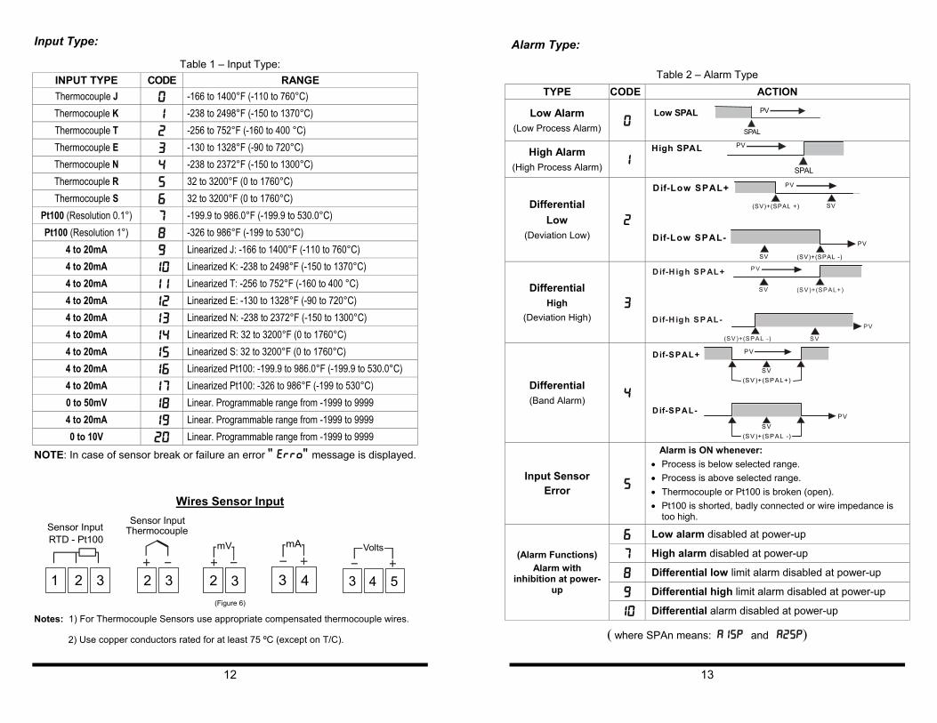
Input Type: Alarm Type:
Table 1 – Input Type: Table 2 – Alarm Type INPUT TYPE CODE RANGE
Thermocouple J 0 -166 to 1400°F (-110 to 760°C) Thermocouple K 1 -238 to 2498°F (-150 to 1370°C) Thermocouple T 2 -256 to 752°F (-160 to 400 °C) Thermocouple E 3 -130 to 1328°F (-90 to 720°C) Thermocouple N 4 -238 to 2372°F (-150 to 1300°C) Thermocouple R 5 32 to 3200°F (0 to 1760°C) Thermocouple S 6 32 to 3200°F (0 to 1760°C)
Pt100 (Resolution 0.1°) 7 -199.9 to 986.0°F (-199.9 to 530.0°C) Pt100 (Resolution 1°) 8 -326 to 986°F (-199 to 530°C)
4 to 20mA 9 Linearized J: -166 to 1400°F (-110 to 760°C) 4 to 20mA 10 Linearized K: -238 to 2498°F (-150 to 1370°C) 4 to 20mA 11 Linearized T: -256 to 752°F (-160 to 400 °C) 4 to 20mA 12 Linearized E: -130 to 1328°F (-90 to 720°C) 4 to 20mA 13 Linearized N: -238 to 2372°F (-150 to 1300°C) 4 to 20mA 14 Linearized R: 32 to 3200°F (0 to 1760°C) 4 to 20mA 15 Linearized S: 32 to 3200°F (0 to 1760°C) 4 to 20mA 16 Linearized Pt100: -199.9 to 986.0°F (-199.9 to 530.0°C) 4 to 20mA 17 Linearized Pt100: -326 to 986°F (-199 to 530°C) 0 to 50mV 18 Linear. Programmable range from -1999 to 9999 4 to 20mA 19 Linear. Programmable range from -1999 to 9999 0 to 10V 20 Linear. Programmable range from -1999 to 9999
TYPE CODE ACTION
Low Alarm (Low Process Alarm) 0
High Alarm (High Process Alarm) 1
Differential Low
(Deviation Low) 2
Differential High
(Deviation High) 3
Differential (Band Alarm) 4
Input Sensor Error 5
Alarm is ON whenever: • Process is below selected range. • Process is above selected range. • Thermocouple or Pt100 is broken (open). • Pt100 is shorted, badly connected or wire impedance is
too high.
6 Low alarm disabled at power-up
7 High alarm disabled at power-up
8 Differential low limit alarm disabled at power-up
9 Differential high limit alarm disabled at power-up
(Alarm Functions) Alarm with
inhibition at power-up
10 Differential alarm disabled at power-up
S P A L
PVL o w S P A L
S P A L
P V H i g h S P A L
(SV)+(SPAL +) SV
PV Dif-Low SPAL+
(SV)+(SPAL -) SV PV Dif-Low SPAL-
(SV)+(SPAL+) SV
PV D if-H igh S P AL+
(SV)+(SPAL -) SV PV D if-H igh S P AL-
(SV )+(SP AL+)
SV
PV Dif-SPAL+
PVSV
Dif-SPAL-
(SV )+(SP AL -)
NOTE: In case of sensor break or failure an error " Erro" message is displayed.
Wires Sensor Input
1 2 3
Sensor Input0
2 3
Sensor InputThermo
2 3
mV
3 4
mA
coupleRTD - Pt10
3 4 5
Volts
(Figure 6)
Notes: 1) For Thermocouple Sensors use appropriate compensated thermocouple wires.
( where SPAn means: A1SP and A2SP)
2) Use copper conductors rated for at least 75 ºC (except on T/C).
12 13

Function Protection (prot): Alarm Functions:
The controller is shipped with full accessibility. If you want to use the “Function Protection” to disable access to cycles 2, 3 and 4, follow the steps below:
Low Alarm: Activates at present value, independent of main setpoint. Low process-alarm activates at and below alarm setting.
• After programming the controller for the desired operation select the level of cycle access desired in Cycle-3 at the prot parameter using the or keys.
High Alarm: Activates at present value, independent of main setpoint. High process-alarm activates at and above alarm setting.
• Remove the controller circuitry from the housing by using the thumb to press the tab in the lower front face of the controller, then, while firmly grabbing the front face at the top and bottom pull it and the circuitry from the case.
Differential Low: Activates at present deviation (negative or positive) value from Alarm Reference ( AL.RE ). Low deviation-alarm activates below alarm setting. Figure 7(a) gives a graphical description of this.
Warning: Use caution when removing the controller from its case, there may be live voltage present at the terminals. This should only be done by a qualified technician. It is recommended that power to the controller be disconnected prior to removing the controller from the case.
Differential High: Activates at present deviation (negative or positive) value from Alarm Reference ( AL.RE ). High deviation-alarm activates above alarm setting. This is represented in figure 7(b).
• View the controller in the position shown in Figure 8 and note the Protection Jumper on the top main board.
Differential: Activates when the process exceeds a specified band-alarm centered around the Alarm Reference ( AL.RE ). See Figure 7(c).
• Enable Function Protection (locks the prot parameter) by placing the jumper over both jumper prongs as shown in figure below.
Inhibition at power-up: Alarm blocking at power-up inhibits the relay alarm from activating when the unit is first energized. The alarm will only trip after the process variable reaches a new alarm situation.
Needle nose pliers are recommended for changing jumper position. • Disable Function Protection (unlocks the prot parameter) by placing the
jumper over both jumper prongs as shown in figure below.
SV SV + ( SPAL - )
AL on AL
on time
Process
SV SV + ( SPAL +)
AL on AL
on time
Process • Once the desired protection is obtained slide the controller back in the case making sure that the main board and power supply board stay in the circuit board channels at the top and bottom side walls of the case. Use the palm of the hand to press the front panel flush into the controller housing.
Dif-Low SPAL - (a) Dif-Low SPAL+
SV SV + ( SPAL + )
AL on
time
Process
SV SV + ( SPAL - )
AL on
time
Process
Dif-High SPAL+ (b) Dif-High SPAL-
SV SV + ( SPAL + )
AL on time
SV + ( SPAL + )
AL on Process
SV SV + ( SPAL - )
AL on
time SV + ( SPAL - )
Process
15
Dif SPAL+ (c) Dif SPAL-
(Figure 7) (Figure 8)
14

PM24 Quick Setup Reference CYCLE 4 - CALIBRATION LEVEL:
NOTE: All input and output types are factory calibrated. This cycle should only be accessed by experienced personnel. If in doubt do not press the or keys in this cycle.
Key and Display Functions
A1 SET UP
A2
Main display: Indicates the process temperature, program parameters and alarms.
A2 LED: Indicates the status of alarm 2.
A1 LED: Indicates the status of alarm 1.
SET UP: Used to move forward throught a menu Cycle. Used to advance to the next Cycle when pressed and held for 4 seconds.
: Used to decrease the value of the displayed parameter.
: Used to increase the value of the displayed parameter.
Inl(
Input Low Calibration
SENSOR OFFSET CALIBRATION. Sets the temperature sensor low calibration (offset). The display shows only the corrected temperature and not the offset added. A signal simulator should be used to inject a low value signal to properly adjust the offset.
InK(
Input High Calibration
INPUT HIGH CALIBRATION. Sets the sensor input circuit gain or high calibration. A signal simulator should be used to inject a high value signal to properly adjust the offset.
(j L
Cold Junction Low Calibration
COLD JUNCTION OFFSET CALIBRATION: Sets the cold junction ºC offset calibration. A good thermometer or a temperature simulator should be used to properly adjust this parameter.
Set Up Cycle Parameters
Cycle-1 Cycle-2 Cycle-3 Cycle-4INDICATION ALARMS CONFIGURATION CALIBRATION
PV Indication
A1SP Alarm 1
Type Input Type
Inl[ Input Low Calibration
A2SP Alarm 2
Dp.po Decimal Point Position
Ink[ Input High Calibration
AL.RE Differential
Vnit Unit
In.ll Input Low Limit
[jl Cold Junction Low
Calibration
In,kl Input High Limit
0ffs
Offset Signal Input
A1fv Alarm 1 Funtion
A2fv Alarm 2 Funtion
A1ky Alarm 1 Hysteresis
A2ky Alarm 2 Hysteresis
Prot Security Protection
16 17
NOTES:
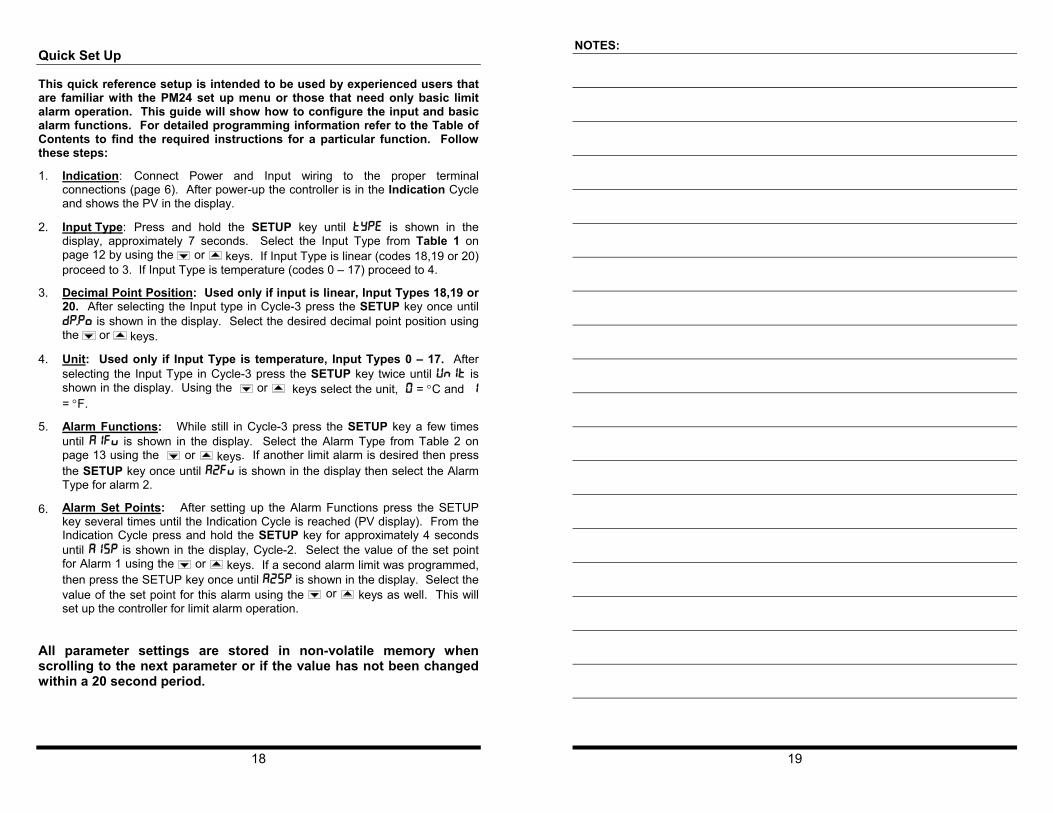
Quick Set Up
This quick reference setup is intended to be used by experienced users that are familiar with the PM24 set up menu or those that need only basic limit alarm operation. This guide will show how to configure the input and basic alarm functions. For detailed programming information refer to the Table of Contents to find the required instructions for a particular function. Follow these steps:
1. Indication: Connect Power and Input wiring to the proper terminal connections (page 6). After power-up the controller is in the Indication Cycle and shows the PV in the display.
2. Input Type: Press and hold the SETUP key until type is shown in the display, approximately 7 seconds. Select the Input Type from Table 1 on page 12 by using the or keys. If Input Type is linear (codes 18,19 or 20) proceed to 3. If Input Type is temperature (codes 0 – 17) proceed to 4.
3. Decimal Point Position: Used only if input is linear, Input Types 18,19 or 20. After selecting the Input type in Cycle-3 press the SETUP key once until dp.po is shown in the display. Select the desired decimal point position using the or keys.
4. Unit: Used only if Input Type is temperature, Input Types 0 – 17. After selecting the Input Type in Cycle-3 press the SETUP key twice until unit is shown in the display. Using the or keys select the unit, 0 = °C and 1 = °F.
5. Alarm Functions: While still in Cycle-3 press the SETUP key a few times until a1fv is shown in the display. Select the Alarm Type from Table 2 on page 13 using the or keys. If another limit alarm is desired then press the SETUP key once until a2fv is shown in the display then select the Alarm Type for alarm 2.
6. Alarm Set Points: After setting up the Alarm Functions press the SETUP key several times until the Indication Cycle is reached (PV display). From the Indication Cycle press and hold the SETUP key for approximately 4 seconds until a1sp is shown in the display, Cycle-2. Select the value of the set point for Alarm 1 using the or keys. If a second alarm limit was programmed, then press the SETUP key once until a2sp is shown in the display. Select the value of the set point for this alarm using the or keys as well. This will set up the controller for limit alarm operation.
All parameter settings are stored in non-volatile memory when scrolling to the next parameter or if the value has not been changed within a 20 second period.
18 19

20
21

22
Error Codes Table for Temperature/Process Controllers
Document # C0504
The connection and configuration errors for most of the problems encountered in using the controller are shown below. A final revision of the connections and parameters will save time and further losses.
Error messages are displayed to help the user to identify possible problems.
Error Codes Table
DisplayShow s
Cause
Process or temperature is below the selected sensor range.
Process or temperature is abov e the selected sensor range.
Sensor error. Example:
1. No connections on the sensor input terminals. 2. Broken thermocouple (open w i re) or broken RTD-Pt100. 3. RTD-Pt100 badly connected, short-circuited or high cable resistance.
RTD-Pt100 badly connected, short-circuited or high cable resistance.
This kind of error is caused when, for instance, a 4-20mA signal goes through the mV or Thermocouples input and can introduce signals of up to 30VDC at the input point and force the Auto/Zero and Auto/Span to w orkoutside the limits that guarantee the precision of the controller. This error goes away w hen the signal is remov ed from the input and the connection is fixed (normally, input signals of up to 30VDC do not damage the controller’s hardw are).
Auto/Zero Problem: This error is caused by a w rong connection and indicates that a voltage greater than 30VDC w as input into the sensor and the Auto/Zero circuit w as damaged. It is necessary to rev i se the controller.
Auto/Span Problem: This error is caused by a w r ong connection and indicates that a v oltage greater than 30VDC w as input into the sensor and the Auto/Span circuit w as damaged. It is necessary to revi se the controller.
NOTE: The controllers do not accept AC-Voltage or AC-Current in the sensor input. This type of signal can damage the controller.
42MPtC onfigura ion S heet
Name: :etaD
Part#:
:tcejorP
Process Setpoint:
Cycle 3C ONF IG UR A NOIT
CODE/VALUE TCARAHC TSIRE TCNUF / SC NOItluafeD I
Cycle 2
SD TCARAHC TSIRE I TCNUF / SC NOI
LA RA Mefault EULAV/EDOC