Embed Size (px)
Citation preview
Errata Sheet
Page 1 of 1
Product Family: DL405
Manual Number D4-HSC-M
Revision and Date Revision A, June 2020
Date: June 1, 2020
This Errata Sheet contains corrections or changes made after the publication of this manual.
Errata Sheet
Changes to Chapter 7. Program Applications
Page 7-2. A Quick Checkout of the Module; Wiring Diagram for Example
The wiring diagram shows +24 VDC going to terminal INA-. This is incorrect; it should be -24 VDC.
Changes to Chapter 1, Getting Started; Chapter 2, Installation and Wiring
Added Note: D4-454 CPU will only support D4-HSC module firmware v2.3

Manual Number D4--HSC--M
Shaded area represents the die-cut covers fromImaging Technologies, 5-98
D4--HSCHigh Speed Counter

WARNING
Thank you for purchasing automation equipment from Automationdirect.com. We want your new DirectLOGICautomation equipment to operate safely. Anyone who installs or uses this equipment should read this publication (andany other relevant publications) before installing or operating the equipment.
To minimize the risk of potential safety problems, you should follow all applicable local and national codes that regulatethe installation and operation of your equipment. These codes vary from area to area and usually change with time. It isyour responsibility to determine which codes should be followed, and to verify that the equipment, installation, andoperation is in compliance with the latest revision of these codes.
At a minimum, you should follow all applicable sections of the National Fire Code, National Electrical Code, and thecodes of the National Electrical Manufacturer’s Association (NEMA). There may be local regulatory or governmentoffices that can also help determine which codes and standards are necessary for safe installation and operation.
Equipment damage or serious injury to personnel can result from the failure to follow all applicable codes andstandards. We do not guarantee the products described in this publication are suitable for your particular application,nor do we assume any responsibility for your product design, installation, or operation.
If you have any questions concerning the installation or operation of this equipment, or if you need additionalinformation, please call us at 1--770--844--4200 or FAX 1--770--886--3199.
This publication is based on information that was available at the time it was printed. At Automationdirect.com weconstantly strive to improve our products and services, so we reserve the right to make changes to the products and/orpublications at any time without notice and without any obligation. This publication may also discuss features that maynot be available in certain revisions of the product.
TrademarksThis publication may contain references to products produced and/or offered by other companies. The product andcompany names may be trademarked and are the sole property of their respective owners. Automationdirect.comdisclaims any proprietary interest in the marks and names of others.
Stage is a trademark of Koyo Electronics Industries Co., LTD. Think & Do Software is a trademark of Think & DoSoftware, Inc. Texas Instruments is a registered trademark of Texas Instruments, Inc. TI, TIWAY, Series 305, Series405, TI305, and TI405 are trademarks of Texas Instruments, Inc. Siemens and SIMATIC are registered trademarks ofSiemens, AG. GE is a registered trademark of General Electric Corporation. Series One is a registered trademark ofGE Fanuc Automation North America, Inc. MODBUS is a registered trademark of Gould, Inc. IBM is a registeredtrademark of International Business Machines. MS-DOS and Microsoft are registered trademarks of MicrosoftCorporation. Windows and Windows NT are trademarks of Microsoft Corporation. OPTOMUX and PAMUX aretrademarks of OPTO 22.
Copyright 1999, Automationdirect.com IncorporatedAll Rights Reserved
No part of this manual shall be copied, reproduced, or transmitted in any way without the prior, written consent ofAutomationdirect.com Incorporated. Automationdirect.com retains the exclusive rights to all informationincluded in this document.
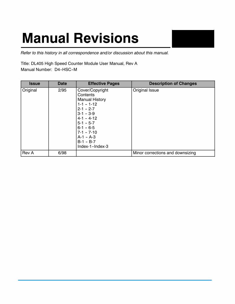
1Manual RevisionsRefer to this history in all correspondence and/or discussion about this manual.
Title: DL405 High Speed Counter Module User Manual, Rev AManual Number: D4--HSC--M
Issue Date Effective Pages Description of Changes
Original 2/95 Cover/CopyrightContentsManual History1-1 -- 1-122-1 -- 2-73-1 -- 3-94-1 -- 4-125-1 -- 5-76-1 -- 6-57-1 -- 7-10A-1 -- A-3B-1 -- B-7Index-1--Index-3
Original Issue
Rev A 6/98 Minor corrections and downsizing
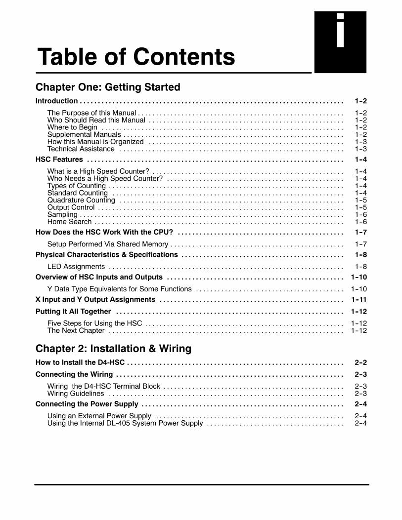
1 iTable of ContentsChapter One: Getting StartedIntroduction 1--2. . . . . . . . . . . . . . . . . . . . . . . . . . . . . . . . . . . . . . . . . . . . . . . . . . . . . . . . . . . . . . . . . . . . . . . . .
The Purpose of this Manual 1--2. . . . . . . . . . . . . . . . . . . . . . . . . . . . . . . . . . . . . . . . . . . . . . . . . . . . . . . . .Who Should Read this Manual 1--2. . . . . . . . . . . . . . . . . . . . . . . . . . . . . . . . . . . . . . . . . . . . . . . . . . . . . .Where to Begin 1--2. . . . . . . . . . . . . . . . . . . . . . . . . . . . . . . . . . . . . . . . . . . . . . . . . . . . . . . . . . . . . . . . . . .Supplemental Manuals 1--2. . . . . . . . . . . . . . . . . . . . . . . . . . . . . . . . . . . . . . . . . . . . . . . . . . . . . . . . . . . . .How this Manual is Organized 1--3. . . . . . . . . . . . . . . . . . . . . . . . . . . . . . . . . . . . . . . . . . . . . . . . . . . . . .Technical Assistance 1--3. . . . . . . . . . . . . . . . . . . . . . . . . . . . . . . . . . . . . . . . . . . . . . . . . . . . . . . . . . . . . .
HSC Features 1--4. . . . . . . . . . . . . . . . . . . . . . . . . . . . . . . . . . . . . . . . . . . . . . . . . . . . . . . . . . . . . . . . . . . . . . .
What is a High Speed Counter? 1--4. . . . . . . . . . . . . . . . . . . . . . . . . . . . . . . . . . . . . . . . . . . . . . . . . . . . .Who Needs a High Speed Counter? 1--4. . . . . . . . . . . . . . . . . . . . . . . . . . . . . . . . . . . . . . . . . . . . . . . . .Types of Counting 1--4. . . . . . . . . . . . . . . . . . . . . . . . . . . . . . . . . . . . . . . . . . . . . . . . . . . . . . . . . . . . . . . . .Standard Counting 1--4. . . . . . . . . . . . . . . . . . . . . . . . . . . . . . . . . . . . . . . . . . . . . . . . . . . . . . . . . . . . . . . .Quadrature Counting 1--5. . . . . . . . . . . . . . . . . . . . . . . . . . . . . . . . . . . . . . . . . . . . . . . . . . . . . . . . . . . . . .Output Control 1--5. . . . . . . . . . . . . . . . . . . . . . . . . . . . . . . . . . . . . . . . . . . . . . . . . . . . . . . . . . . . . . . . . . . .Sampling 1--6. . . . . . . . . . . . . . . . . . . . . . . . . . . . . . . . . . . . . . . . . . . . . . . . . . . . . . . . . . . . . . . . . . . . . . . . .Home Search 1--6. . . . . . . . . . . . . . . . . . . . . . . . . . . . . . . . . . . . . . . . . . . . . . . . . . . . . . . . . . . . . . . . . . . . .
How Does the HSC Work With the CPU? 1--7. . . . . . . . . . . . . . . . . . . . . . . . . . . . . . . . . . . . . . . . . . . . . .
Setup Performed Via Shared Memory 1--7. . . . . . . . . . . . . . . . . . . . . . . . . . . . . . . . . . . . . . . . . . . . . . . .Physical Characteristics & Specifications 1--8. . . . . . . . . . . . . . . . . . . . . . . . . . . . . . . . . . . . . . . . . . . . .
LED Assignments 1--8. . . . . . . . . . . . . . . . . . . . . . . . . . . . . . . . . . . . . . . . . . . . . . . . . . . . . . . . . . . . . . . . .Overview of HSC Inputs and Outputs 1--10. . . . . . . . . . . . . . . . . . . . . . . . . . . . . . . . . . . . . . . . . . . . . . . . .
Y Data Type Equivalents for Some Functions 1--10. . . . . . . . . . . . . . . . . . . . . . . . . . . . . . . . . . . . . . . . .X Input and Y Output Assignments 1--11. . . . . . . . . . . . . . . . . . . . . . . . . . . . . . . . . . . . . . . . . . . . . . . . . . .
Putting It All Together 1--12. . . . . . . . . . . . . . . . . . . . . . . . . . . . . . . . . . . . . . . . . . . . . . . . . . . . . . . . . . . . . . .
Five Steps for Using the HSC 1--12. . . . . . . . . . . . . . . . . . . . . . . . . . . . . . . . . . . . . . . . . . . . . . . . . . . . . . .The Next Chapter 1--12. . . . . . . . . . . . . . . . . . . . . . . . . . . . . . . . . . . . . . . . . . . . . . . . . . . . . . . . . . . . . . . . .
Chapter 2: Installation & WiringHow to Install the D4-HSC 2--2. . . . . . . . . . . . . . . . . . . . . . . . . . . . . . . . . . . . . . . . . . . . . . . . . . . . . . . . . . . .
Connecting the Wiring 2--3. . . . . . . . . . . . . . . . . . . . . . . . . . . . . . . . . . . . . . . . . . . . . . . . . . . . . . . . . . . . . . .
Wiring the D4-HSC Terminal Block 2--3. . . . . . . . . . . . . . . . . . . . . . . . . . . . . . . . . . . . . . . . . . . . . . . . . .Wiring Guidelines 2--3. . . . . . . . . . . . . . . . . . . . . . . . . . . . . . . . . . . . . . . . . . . . . . . . . . . . . . . . . . . . . . . . .
Connecting the Power Supply 2--4. . . . . . . . . . . . . . . . . . . . . . . . . . . . . . . . . . . . . . . . . . . . . . . . . . . . . . . .
Using an External Power Supply 2--4. . . . . . . . . . . . . . . . . . . . . . . . . . . . . . . . . . . . . . . . . . . . . . . . . . . .Using the Internal DL-405 System Power Supply 2--4. . . . . . . . . . . . . . . . . . . . . . . . . . . . . . . . . . . . . .
iiTable of Contents
Count Input Wiring Diagram 2--5. . . . . . . . . . . . . . . . . . . . . . . . . . . . . . . . . . . . . . . . . . . . . . . . . . . . . . . . . .
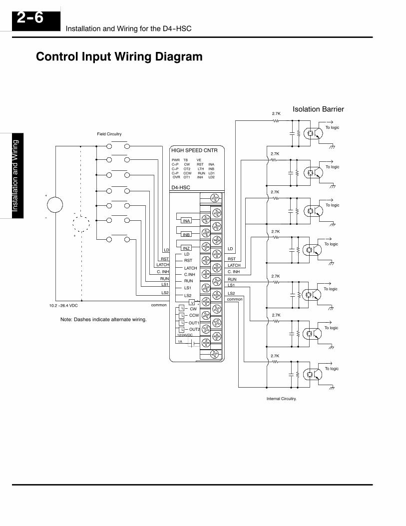
Control Input Wiring Diagram 2--6. . . . . . . . . . . . . . . . . . . . . . . . . . . . . . . . . . . . . . . . . . . . . . . . . . . . . . . .
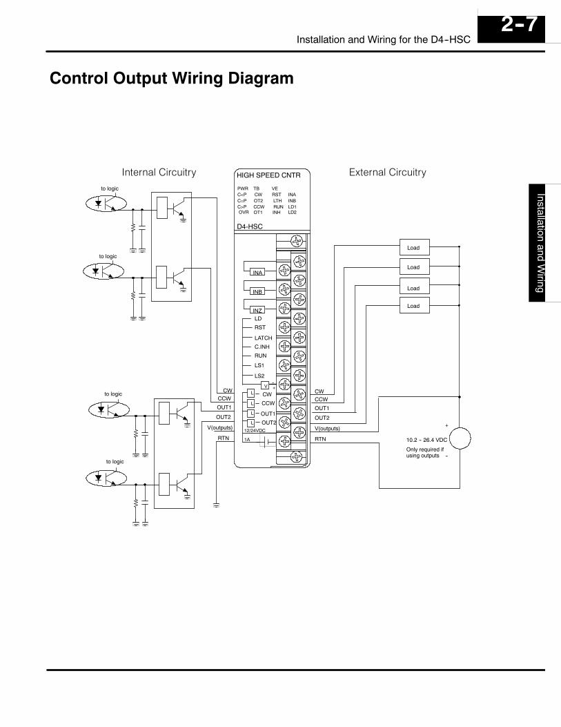
Control Output Wiring Diagram 2--7. . . . . . . . . . . . . . . . . . . . . . . . . . . . . . . . . . . . . . . . . . . . . . . . . . . . . . .
Chapter 3: Understanding the OperationThe Operating Basics 3--2. . . . . . . . . . . . . . . . . . . . . . . . . . . . . . . . . . . . . . . . . . . . . . . . . . . . . . . . . . . . . . . .
Assigning Your Data Types 3--3. . . . . . . . . . . . . . . . . . . . . . . . . . . . . . . . . . . . . . . . . . . . . . . . . . . . . . . . . . .
Automatic Configuration 3--3. . . . . . . . . . . . . . . . . . . . . . . . . . . . . . . . . . . . . . . . . . . . . . . . . . . . . . . . . . . .Using the X and Y Assignment Table 3--4. . . . . . . . . . . . . . . . . . . . . . . . . . . . . . . . . . . . . . . . . . . . . . . . .I/O Assignment Table 3--5. . . . . . . . . . . . . . . . . . . . . . . . . . . . . . . . . . . . . . . . . . . . . . . . . . . . . . . . . . . . . .
Reading and Writing Shared Memory 3--6. . . . . . . . . . . . . . . . . . . . . . . . . . . . . . . . . . . . . . . . . . . . . . . . .
Contents and Data Flow 3--6. . . . . . . . . . . . . . . . . . . . . . . . . . . . . . . . . . . . . . . . . . . . . . . . . . . . . . . . . . . .The Two-Step Process for Writing Data to Shared Memory 3--7. . . . . . . . . . . . . . . . . . . . . . . . . . . . .Reading Data From Shared Memory 3--7. . . . . . . . . . . . . . . . . . . . . . . . . . . . . . . . . . . . . . . . . . . . . . . . .
Understanding How Numbers are Stored In Shared Memory 3--8. . . . . . . . . . . . . . . . . . . . . . . . . . . .
Why is it important? 3--8. . . . . . . . . . . . . . . . . . . . . . . . . . . . . . . . . . . . . . . . . . . . . . . . . . . . . . . . . . . . . . .Allocating the 4 Bytes of Memory 3--8. . . . . . . . . . . . . . . . . . . . . . . . . . . . . . . . . . . . . . . . . . . . . . . . . . . .Dealing With the Negative Numbers 3--9. . . . . . . . . . . . . . . . . . . . . . . . . . . . . . . . . . . . . . . . . . . . . . . . .Placing a Negative Number into Shared Memory 3--9. . . . . . . . . . . . . . . . . . . . . . . . . . . . . . . . . . . . . .The Next Chapter 3--9. . . . . . . . . . . . . . . . . . . . . . . . . . . . . . . . . . . . . . . . . . . . . . . . . . . . . . . . . . . . . . . . .
Chapter Four: Setting Up and Controlling the CountingIntroduction to Using DirectSOFT 4--2. . . . . . . . . . . . . . . . . . . . . . . . . . . . . . . . . . . . . . . . . . . . . . . . . . . .
Selecting the Counting Mode 4--3. . . . . . . . . . . . . . . . . . . . . . . . . . . . . . . . . . . . . . . . . . . . . . . . . . . . . . . . .
Determining Which Mode to Use 4--3. . . . . . . . . . . . . . . . . . . . . . . . . . . . . . . . . . . . . . . . . . . . . . . . . . . .Ladder Logic for Determining the Counting Mode 4--3. . . . . . . . . . . . . . . . . . . . . . . . . . . . . . . . . . . . . .
Selecting the Counting Direction 4--4. . . . . . . . . . . . . . . . . . . . . . . . . . . . . . . . . . . . . . . . . . . . . . . . . . . . .
How Ym+13 and Ym+14 Together Determine Counting Direction 4--4. . . . . . . . . . . . . . . . . . . . . . . .Ladder Logic to Select Counting Direction 4--4. . . . . . . . . . . . . . . . . . . . . . . . . . . . . . . . . . . . . . . . . . . .
Selecting the Counting Resolution 4--5. . . . . . . . . . . . . . . . . . . . . . . . . . . . . . . . . . . . . . . . . . . . . . . . . . . .
Choose from 3 Resolution Settings 4--6. . . . . . . . . . . . . . . . . . . . . . . . . . . . . . . . . . . . . . . . . . . . . . . . . .Why Change the Counting Resolution? 4--6. . . . . . . . . . . . . . . . . . . . . . . . . . . . . . . . . . . . . . . . . . . . . .Example RLL: 2x Resolution 4--6. . . . . . . . . . . . . . . . . . . . . . . . . . . . . . . . . . . . . . . . . . . . . . . . . . . . . . . .Example RLL: 4x Resolution 4--6. . . . . . . . . . . . . . . . . . . . . . . . . . . . . . . . . . . . . . . . . . . . . . . . . . . . . . . .Default Setting 4--6. . . . . . . . . . . . . . . . . . . . . . . . . . . . . . . . . . . . . . . . . . . . . . . . . . . . . . . . . . . . . . . . . . .
Specifying an Offset 4--7. . . . . . . . . . . . . . . . . . . . . . . . . . . . . . . . . . . . . . . . . . . . . . . . . . . . . . . . . . . . . . . . .
What is an Offset? 4--7. . . . . . . . . . . . . . . . . . . . . . . . . . . . . . . . . . . . . . . . . . . . . . . . . . . . . . . . . . . . . . . . .External Method 4--7. . . . . . . . . . . . . . . . . . . . . . . . . . . . . . . . . . . . . . . . . . . . . . . . . . . . . . . . . . . . . . . . . .Internal Method 4--7. . . . . . . . . . . . . . . . . . . . . . . . . . . . . . . . . . . . . . . . . . . . . . . . . . . . . . . . . . . . . . . . . . .
Specifying a Preset 4--8. . . . . . . . . . . . . . . . . . . . . . . . . . . . . . . . . . . . . . . . . . . . . . . . . . . . . . . . . . . . . . . . . .
What is a Preset? 4--8. . . . . . . . . . . . . . . . . . . . . . . . . . . . . . . . . . . . . . . . . . . . . . . . . . . . . . . . . . . . . . . . .How Does the Preset Affect the Outputs? 4--8. . . . . . . . . . . . . . . . . . . . . . . . . . . . . . . . . . . . . . . . . . . .Loading the Preset Into Shared Memory 4--8. . . . . . . . . . . . . . . . . . . . . . . . . . . . . . . . . . . . . . . . . . . . .Checking the Status of Preset Relative to Current Count 4--8. . . . . . . . . . . . . . . . . . . . . . . . . . . . . . .
iiiTable of Contents
Starting and Resetting the Current Count 4--9. . . . . . . . . . . . . . . . . . . . . . . . . . . . . . . . . . . . . . . . . . . . .
Starting the Counter 4--9. . . . . . . . . . . . . . . . . . . . . . . . . . . . . . . . . . . . . . . . . . . . . . . . . . . . . . . . . . . . . . .Automatically Resetting the Counter 4--9. . . . . . . . . . . . . . . . . . . . . . . . . . . . . . . . . . . . . . . . . . . . . . . . .Internal Reset 4--9. . . . . . . . . . . . . . . . . . . . . . . . . . . . . . . . . . . . . . . . . . . . . . . . . . . . . . . . . . . . . . . . . . . . .External Reset Using RST 4--9. . . . . . . . . . . . . . . . . . . . . . . . . . . . . . . . . . . . . . . . . . . . . . . . . . . . . . . . . .Summary of Reset Count Relays 4--9. . . . . . . . . . . . . . . . . . . . . . . . . . . . . . . . . . . . . . . . . . . . . . . . . . . .External Reset Using INZ 4--10. . . . . . . . . . . . . . . . . . . . . . . . . . . . . . . . . . . . . . . . . . . . . . . . . . . . . . . . . .
Latching or Inhibiting the Current Count 4--11. . . . . . . . . . . . . . . . . . . . . . . . . . . . . . . . . . . . . . . . . . . . . .
What Does Latching Do? 4--11. . . . . . . . . . . . . . . . . . . . . . . . . . . . . . . . . . . . . . . . . . . . . . . . . . . . . . . . . . .How Do You Trigger the Latching Process? 4--11. . . . . . . . . . . . . . . . . . . . . . . . . . . . . . . . . . . . . . . . . . .Sample RLL for Latching 4--11. . . . . . . . . . . . . . . . . . . . . . . . . . . . . . . . . . . . . . . . . . . . . . . . . . . . . . . . . . .What Is Meant By Inhibiting the Count? 4--11. . . . . . . . . . . . . . . . . . . . . . . . . . . . . . . . . . . . . . . . . . . . . .How Do You Inhibit the Count? 4--11. . . . . . . . . . . . . . . . . . . . . . . . . . . . . . . . . . . . . . . . . . . . . . . . . . . . . .Sample RLL for Inhibiting the Count 4--11. . . . . . . . . . . . . . . . . . . . . . . . . . . . . . . . . . . . . . . . . . . . . . . . .Summary of Latch and Inhibiting Output Relays 4--11. . . . . . . . . . . . . . . . . . . . . . . . . . . . . . . . . . . . . . .
Monitoring Overflow and Resetting Flags 4--12. . . . . . . . . . . . . . . . . . . . . . . . . . . . . . . . . . . . . . . . . . . . .
What is a Counting Overflow? 4--12. . . . . . . . . . . . . . . . . . . . . . . . . . . . . . . . . . . . . . . . . . . . . . . . . . . . . . .Status Flag for Overflow 4--12. . . . . . . . . . . . . . . . . . . . . . . . . . . . . . . . . . . . . . . . . . . . . . . . . . . . . . . . . . .Tracking Overflows 4--12. . . . . . . . . . . . . . . . . . . . . . . . . . . . . . . . . . . . . . . . . . . . . . . . . . . . . . . . . . . . . . . .Summary of Input and Output Relays for Overflow and Flag Reset 4--12. . . . . . . . . . . . . . . . . . . . . . .
Chapter Five: Controlling the OuputsIntroduction 5--2. . . . . . . . . . . . . . . . . . . . . . . . . . . . . . . . . . . . . . . . . . . . . . . . . . . . . . . . . . . . . . . . . . . . . . . . .
The 4 Control Outputs 5--2. . . . . . . . . . . . . . . . . . . . . . . . . . . . . . . . . . . . . . . . . . . . . . . . . . . . . . . . . . . . .All the Output Signals Look the Same 5--2. . . . . . . . . . . . . . . . . . . . . . . . . . . . . . . . . . . . . . . . . . . . . . . .The 4 Output Relays for Turning ON Each Control Output 5--2. . . . . . . . . . . . . . . . . . . . . . . . . . . . . .Using the Internal Relays to Control the Outputs is Optional 5--2. . . . . . . . . . . . . . . . . . . . . . . . . . . .
Manual Output Control 5--3. . . . . . . . . . . . . . . . . . . . . . . . . . . . . . . . . . . . . . . . . . . . . . . . . . . . . . . . . . . . . . .
Using Ym+6 and Ym+23 to turn direction outputs ON or OFF 5--3. . . . . . . . . . . . . . . . . . . . . . . . . .Automatic Output Control 5--3. . . . . . . . . . . . . . . . . . . . . . . . . . . . . . . . . . . . . . . . . . . . . . . . . . . . . . . . . . . .
Also Called HSC RUN 5--3. . . . . . . . . . . . . . . . . . . . . . . . . . . . . . . . . . . . . . . . . . . . . . . . . . . . . . . . . . . . .How Do You Invoke HSC RUN? 5--3. . . . . . . . . . . . . . . . . . . . . . . . . . . . . . . . . . . . . . . . . . . . . . . . . . . . .Example of Using Ym+3 to Activate HSC RUN 5--3. . . . . . . . . . . . . . . . . . . . . . . . . . . . . . . . . . . . . . . .
Using the Direction Outputs 5--4. . . . . . . . . . . . . . . . . . . . . . . . . . . . . . . . . . . . . . . . . . . . . . . . . . . . . . . . . .
What is a Direction Output? 5--4. . . . . . . . . . . . . . . . . . . . . . . . . . . . . . . . . . . . . . . . . . . . . . . . . . . . . . . .How the HSC Knows When to Turn ON CW or CCW 5--4. . . . . . . . . . . . . . . . . . . . . . . . . . . . . . . . . . .
Timing Diagrams for HSC RUN 5--5. . . . . . . . . . . . . . . . . . . . . . . . . . . . . . . . . . . . . . . . . . . . . . . . . . . . . . .
Current Count < Preset 5--5. . . . . . . . . . . . . . . . . . . . . . . . . . . . . . . . . . . . . . . . . . . . . . . . . . . . . . . . . . . .Current Count = Preset 5--5. . . . . . . . . . . . . . . . . . . . . . . . . . . . . . . . . . . . . . . . . . . . . . . . . . . . . . . . . . . .Current Count > Preset 5--5. . . . . . . . . . . . . . . . . . . . . . . . . . . . . . . . . . . . . . . . . . . . . . . . . . . . . . . . . . . .
Using the Speed Outputs with the Direction Outputs 5--6. . . . . . . . . . . . . . . . . . . . . . . . . . . . . . . . . . .
What are the Speed Outputs? 5--6. . . . . . . . . . . . . . . . . . . . . . . . . . . . . . . . . . . . . . . . . . . . . . . . . . . . . .2 Ways to Initiate OUT1 and OUT2 5--6. . . . . . . . . . . . . . . . . . . . . . . . . . . . . . . . . . . . . . . . . . . . . . . . . .Using HSC RUN to Initiate OUT1 5--6. . . . . . . . . . . . . . . . . . . . . . . . . . . . . . . . . . . . . . . . . . . . . . . . . . . .How OUT2 is Initiated in HSC RUN 5--6. . . . . . . . . . . . . . . . . . . . . . . . . . . . . . . . . . . . . . . . . . . . . . . . . .Monitoring Speed Output Status 5--6. . . . . . . . . . . . . . . . . . . . . . . . . . . . . . . . . . . . . . . . . . . . . . . . . . . .Figure A: Example of Outputs (Decel=1000, Preset=3000, Current Count >Preset) 5--6. . . . . . . .Figure B: Example of Outputs (Decel=1000, Preset=3000, Current Count<Preset) 5--6. . . . . . . . .
ivTable of Contents
Chapter Six: Special FeaturesPlanning a Home Search Application 6--2. . . . . . . . . . . . . . . . . . . . . . . . . . . . . . . . . . . . . . . . . . . . . . . . .
Requirements for Home Search 6--2. . . . . . . . . . . . . . . . . . . . . . . . . . . . . . . . . . . . . . . . . . . . . . . . . . . . .Example of Home Search Application 6--2. . . . . . . . . . . . . . . . . . . . . . . . . . . . . . . . . . . . . . . . . . . . . . . .
Using Sampling 6--4. . . . . . . . . . . . . . . . . . . . . . . . . . . . . . . . . . . . . . . . . . . . . . . . . . . . . . . . . . . . . . . . . . . . .
Why Use Sampling? 6--4. . . . . . . . . . . . . . . . . . . . . . . . . . . . . . . . . . . . . . . . . . . . . . . . . . . . . . . . . . . . . . .Enabling and Monitoring the Sampling 6--4. . . . . . . . . . . . . . . . . . . . . . . . . . . . . . . . . . . . . . . . . . . . . . .How to Calculate the Timebase 6--5. . . . . . . . . . . . . . . . . . . . . . . . . . . . . . . . . . . . . . . . . . . . . . . . . . . . .What Happens If You Want to Enter a Value with Decimal Points? 6--5. . . . . . . . . . . . . . . . . . . . . . .Summary of Input and Output Relays for Sampling 6--5. . . . . . . . . . . . . . . . . . . . . . . . . . . . . . . . . . . .
Chapter Seven: Program ApplicationsA Quick Checkout of the Module 7--1. . . . . . . . . . . . . . . . . . . . . . . . . . . . . . . . . . . . . . . . . . . . . . . . . . . . .
What It Does 7--2. . . . . . . . . . . . . . . . . . . . . . . . . . . . . . . . . . . . . . . . . . . . . . . . . . . . . . . . . . . . . . . . . . . . .How It Works 7--2. . . . . . . . . . . . . . . . . . . . . . . . . . . . . . . . . . . . . . . . . . . . . . . . . . . . . . . . . . . . . . . . . . . . .Things You Need for the Example 7--2. . . . . . . . . . . . . . . . . . . . . . . . . . . . . . . . . . . . . . . . . . . . . . . . . . .Wiring Diagram for the Example 7--2. . . . . . . . . . . . . . . . . . . . . . . . . . . . . . . . . . . . . . . . . . . . . . . . . . . . .RLL Program for Quick Checkout of the Module 7--3. . . . . . . . . . . . . . . . . . . . . . . . . . . . . . . . . . . . . . .
Application No.1: Drilling Operation 7--4. . . . . . . . . . . . . . . . . . . . . . . . . . . . . . . . . . . . . . . . . . . . . . . . . .
Ladder Logic for Drilling Operation 7--5. . . . . . . . . . . . . . . . . . . . . . . . . . . . . . . . . . . . . . . . . . . . . . . . . . .Application No. 2: Cut--to--Length Operation 7--8. . . . . . . . . . . . . . . . . . . . . . . . . . . . . . . . . . . . . . . . . . .
Ladder Logic for Cut--to--Length Operation 7--9. . . . . . . . . . . . . . . . . . . . . . . . . . . . . . . . . . . . . . . . . . .
Appendix A: Introduction to Motor Drives and EncodersWhat is a Drive and How Does It Connect to the HSC? A--2. . . . . . . . . . . . . . . . . . . . . . . . . . . . . . . . .
What is an Encoder and How Does It Connect to the HSC? A--3. . . . . . . . . . . . . . . . . . . . . . . . . . . . .How the Incremental Encoder Works A--3. . . . . . . . . . . . . . . . . . . . . . . . . . . . . . . . . . . . . . . . . . . . . . . .What is the Z-Marker? A--3. . . . . . . . . . . . . . . . . . . . . . . . . . . . . . . . . . . . . . . . . . . . . . . . . . . . . . . . . . . . .
Appendix B: Summary of Tables and Charts Presented in the TextSpecifications B--2. . . . . . . . . . . . . . . . . . . . . . . . . . . . . . . . . . . . . . . . . . . . . . . . . . . . . . . . . . . . . . . . . . . . . . .
X and Y Assignment Table B--4. . . . . . . . . . . . . . . . . . . . . . . . . . . . . . . . . . . . . . . . . . . . . . . . . . . . . . . . . . .
Shared Memory Table B--5. . . . . . . . . . . . . . . . . . . . . . . . . . . . . . . . . . . . . . . . . . . . . . . . . . . . . . . . . . . . . . . .
Table for Determining Count Direction B--6. . . . . . . . . . . . . . . . . . . . . . . . . . . . . . . . . . . . . . . . . . . . . . . .
Counting Resolution Table (Quadrature Only) B--7. . . . . . . . . . . . . . . . . . . . . . . . . . . . . . . . . . . . . . . . .
11Getting Started
In This Chapter. . . .— Introduction— HSC Features— How Does the HSC Work With the CPU?— Physical Characteristics & Specifications— Overview of HSC Inputs and Outputs— X Input and Y Output Assignments— Putting It All Together
D4-
-HS
CG
ettin
gS
tarte
d1--2
Getting Started
Introduction
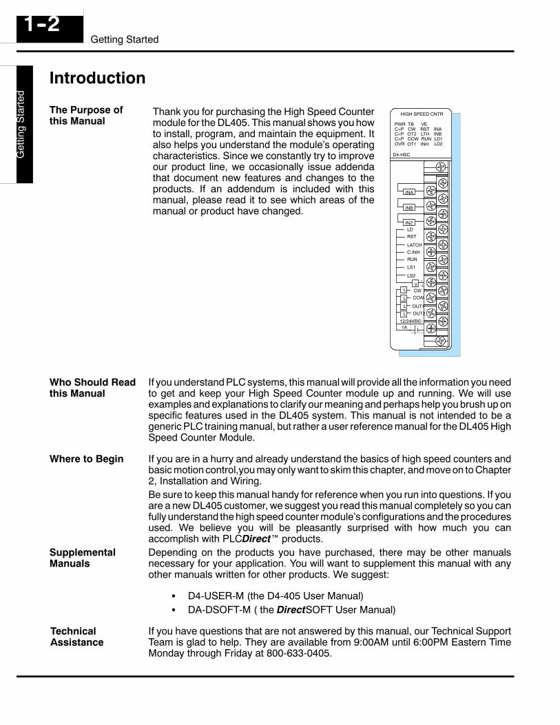
Thank you for purchasing the High Speed Countermodule for the DL405. This manual shows you howto install, program, and maintain the equipment. Italso helps you understand the module’s operatingcharacteristics. Since we constantly try to improveour product line, we occasionally issue addendathat document new features and changes to theproducts. If an addendum is included with thismanual, please read it to see which areas of themanual or product have changed.
PWRC<PC=PC>P
TBCWOT2CCW
HIGH SPEED CNTR
VERSTLTHRUN
INAINB
OVR
D4-HSC
OT1 INHLD1LD2
INA
INB
INZ
--+V
LDRST
LATCHC.INHRUN
LS1
LS2
L
L
L
L
CWCCW
OUT1OUT2
12/24VDC1A
If you understand PLC systems, this manual will provide all the information you needto get and keep your High Speed Counter module up and running. We will useexamples and explanations to clarify our meaning and perhaps help you brush up onspecific features used in the DL405 system. This manual is not intended to be ageneric PLC training manual, but rather a user reference manual for the DL405 HighSpeed Counter Module.
If you are in a hurry and already understand the basics of high speed counters andbasic motion control,you may only want to skim this chapter, and move on to Chapter2, Installation and Wiring.Be sure to keep this manual handy for reference when you run into questions. If youare a new DL405 customer, we suggest you read this manual completely so you canfully understand the high speed counter module’s configurations and the proceduresused. We believe you will be pleasantly surprised with how much you canaccomplish with PLCDirect products.Depending on the products you have purchased, there may be other manualsnecessary for your application. You will want to supplement this manual with anyother manuals written for other products. We suggest:
S D4-USER-M (the D4-405 User Manual)S DA-DSOFT-M ( the DirectSOFT User Manual)
If you have questions that are not answered by this manual, our Technical SupportTeam is glad to help. They are available from 9:00AM until 6:00PM Eastern TimeMonday through Friday at 800-633-0405.
The Purpose ofthis Manual
Who Should Readthis Manual
Where to Begin
SupplementalManuals
TechnicalAssistance
D4--H
SC
Getting
Started
1--3Getting Started
Below is a table showing a summary of contents provided within each section of thismanual. The manual is organized into the following seven chapters:
Getting Startedincludes a brief description of the high speed countermodule, common applications for high speed counters, andan overview of the steps necessary to setup and operate thehigh speed counter.
Installation and Wiring shows you step-by-step how to install and wire the HSC.Includes wiring diagrams.
UnderstandingOperation
a must for understanding the rest of the manual. It covers theshared memory concept, the assignment of data types forthe HSC, and how values are stored.
Setting Up andControlling the Count
covers offsets and presets, which are needed for manyapplications. It provides the programming tools needed tomake full use of the counting capability. It includes countinhibiting, count latching and overflow flags.
Controlling the Outputs
this chapter introduces you to the HSC’s four different controloutputs. It shows you how HSC RUN uses your presetinformation and current count to trigger the outputs in anordered format. It also covers “manual’ operation of theoutputs without using HSC RUN.
Special Featurescovers two special features that have been built into theHSC. You will learn about sampling and home searchcapabilities.
Applicationsshows you how to write programs that will provide possiblesolutions for some common applications you mightencounter.
Introduction to MotorDrives and Shaft Encoders
although PLCDirect does not provide encoders or motordrives, we have included a brief overview explaining some ofthe more common encoders and electronic drives that maybe used with the D4-HSC High Speed Counter.
Introduction to MotorDrives and Shaft Encoders
this includes the X and Y data type assignment chart and anaddress map for the seven shared memory parameters.
You can also check our online resources for the latest product support information:S Internet -- the address of our Web site is http://www.plcdirect.comS Bulletin Board Service (BBS) -- call (770) 844--4209
The “note pad” icon in the left-hand margin indicates the paragraph to its immediateright will be a special note.
The “exclamation mark” icon in the left-hand margin indicates the paragraph to itsimmediate right will be a warning or caution. These are very important because theinformation may help you prevent serious personal injury or equipment damage.
Chapters
1
23
4
5
67
Appendices
A
BOther Resources
D4-
-HS
CG
ettin
gS
tarte
d1--4
Getting Started
HSC Features
Literally, high speed counters count fast! The D4-HSC high speed counter has onechannel for counting pulses from sensors, encoders, switches, and so on, at rates upto 100 kHz (50% duty cycle). It is designed to make your job simpler. The HSC has itsown microprocessor that asynchronously counts and accumulates the high speedpulses. This means the main CPU of the DL405 is free to do the other importanttasks. It can simply check the accumulated count when it needs to do so.
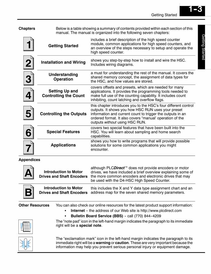
If you have an application that needs tocount pulses rapidly, then you are aprime candidate for an HSC. TheD4-HSC also has 4 outputs that can beused for controlling motor speed anddirection. There is one specialrequirement. The variable speed motorsor motor drives that are used must becapable of changing speed whenreceiving a voltage input between 10.2VDC and 26.4 VDC. Many digital drivesbeing offered today offer programmableinput capability, precisely for this sort ofapplication.
CW or CCW
OUT2
OUT1
INA
INB
encoder
CPU
drive
HSC4 Outputs:
INZ
3 Counting Inputs:
NOTE: The motor control capability should not be confused with a pulse outputcapability such as used with stepper motors. The D4-HSC outputs a voltage leveldependent on an external power supply and does not have pulse outputcapability. You should check the specs of your drive or motor carefully to makecertain that the specifications of this module match your application requirements.
The D4-HSC can do standard UP and DOWN counting or it can do quadraturecounting. These are software selectable as two different modes.
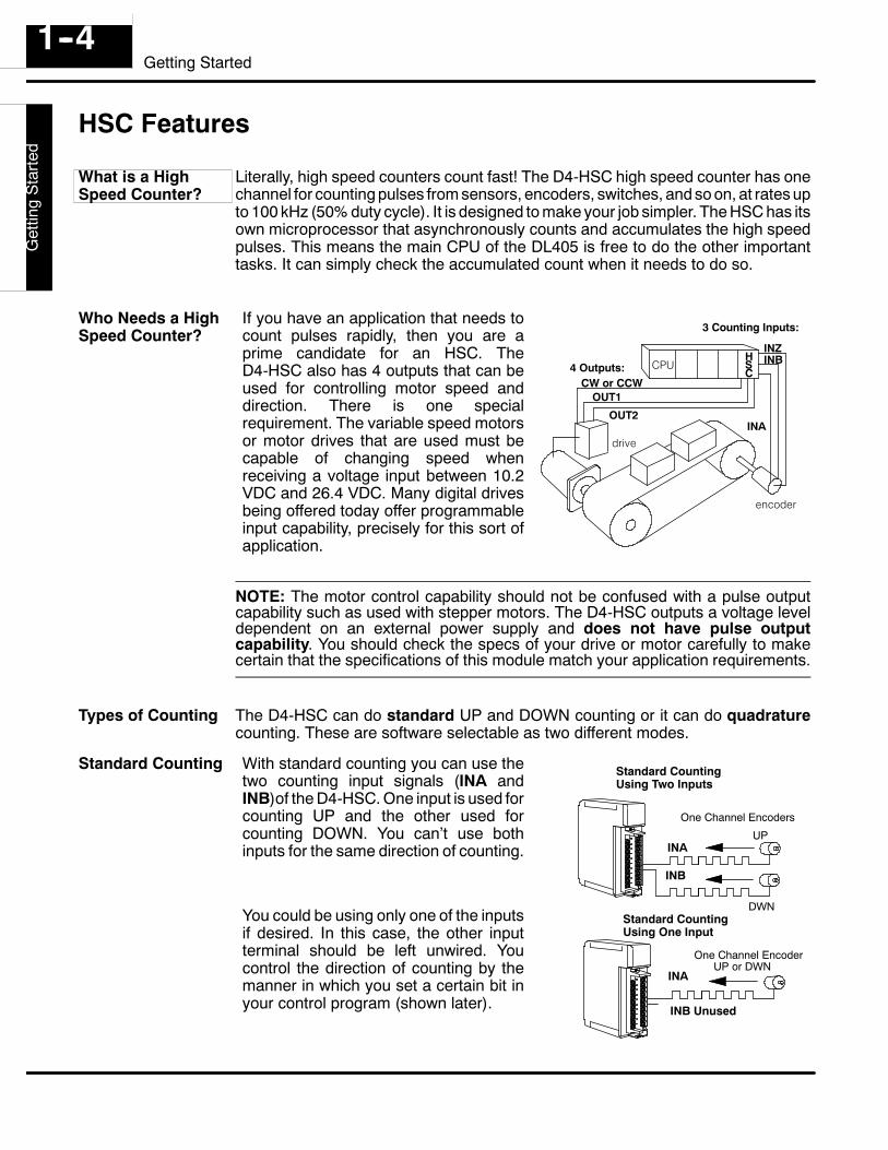
With standard counting you can use thetwo counting input signals (INA andINB)of the D4-HSC. One input is used forcounting UP and the other used forcounting DOWN. You can’t use bothinputs for the same direction of counting.
You could be using only one of the inputsif desired. In this case, the other inputterminal should be left unwired. Youcontrol the direction of counting by themanner in which you set a certain bit inyour control program (shown later).
One Channel Encoders
Standard CountingUsing Two Inputs
INA
INB
One Channel Encoder
INA
INB Unused
Standard CountingUsing One Input
UP
DWN
UP or DWN
What is a HighSpeed Counter?
Who Needs a HighSpeed Counter?
Types of Counting
Standard Counting
D4--H
SC
Getting
Started
1--5Getting Started
With quadrature counting, you must useboth signals (INA and INB). Both inputterminals are connected to the same fielddevice, capable of outputting two squarewave signals, each being offset 90degrees. Quadrature counting is oftenpreferred to standard counting because itcan sense direction. Quadrature inputs arealso more noise immune. With quadraturecounting, the direction (UP or DOWNcounting) is determined by whether thesignal being received at INA leads or lagsthe signal received at INB. The D4-HSClooks at the signals coming in andcompares them. It then determines whichis leading and which is lagging. NOTE: Wehave not shown the optional use of theZ-output signal (connected to INZ of theHSC) that comes standard on mostquadrature encoders. The use of this inputoption will be discussed when we coverresetting the counter externally and theautomatic home search feature.
Quadrature Encoder
Quadrature Counting
Leading and lagging signals
INA
INB
With a rotary encoder, the leading andlagging signal is determined by whichdirection the shaft is turning. This is howquadrature counting is able to sensedirection.
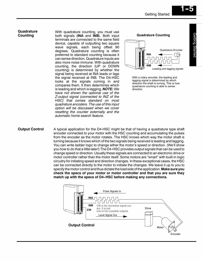
A typical application for the D4-HSC might be that of having a quadrature type shaftencoder connected to your motor with the HSC counting and accumulating the pulsesfrom the encoder as the motor rotates. The HSC knows which way the motor shaft isturning because it knows which of the two signals being received is leading and lagging.You can write ladder logic to change either the motor’s speed or direction. (We’ll showyou how to do that a little later!) The D4-HSC provides output signals that can be used tochange speed or direction. Usually these signals are connected to an electronic drive ormotor controller rather than the motor itself. Some motors are “smart” with built-in logiccircuitry for initiating speed and direction changes. In these exceptional cases, the HSCcan be connected directly to the motor to initiate the changes. We leave it up to you tospecify the motor control and thus dictate the loadside of the application.Make sureyoucheck the specs of your motor or motor controller and that you are sure theymatch up with the specs of D4--HSC before making any connections.
Level Signal Out
Drive
Motor
Encoder
Pulse Signals In
INA
INB
CW
CW is the clockwise signal out-put. It is justone of four possible outputs.
Output Control
QuadratureCounting
Output Control
D4-
-HS
CG
ettin
gS
tarte
d1--6
Getting Started
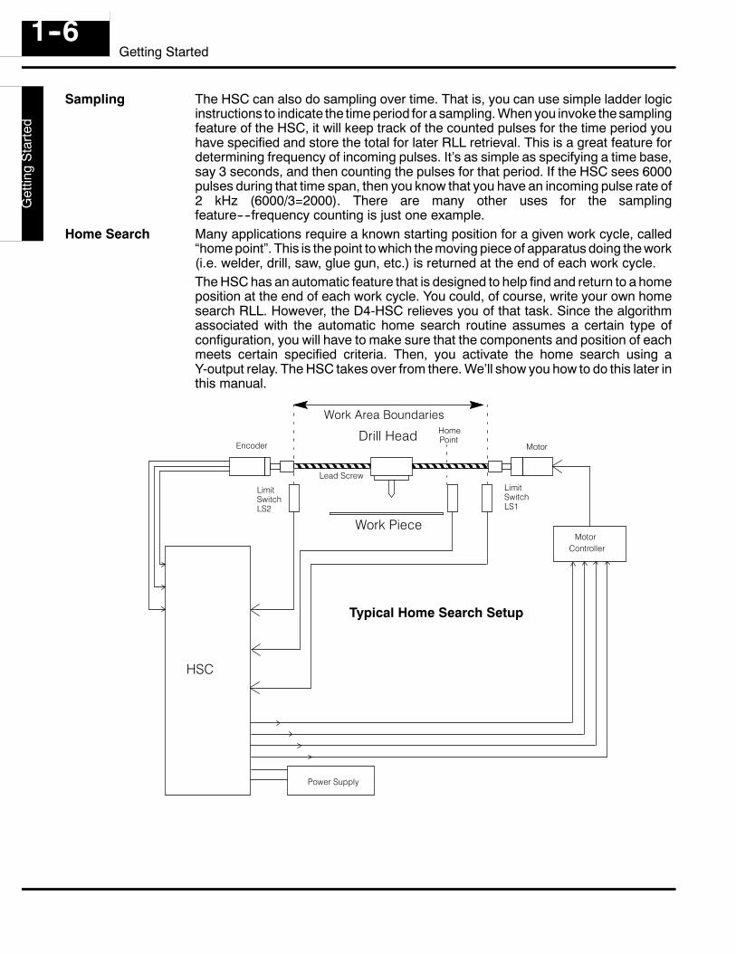
The HSC can also do sampling over time. That is, you can use simple ladder logicinstructions to indicate the time period for a sampling. When you invoke the samplingfeature of the HSC, it will keep track of the counted pulses for the time period youhave specified and store the total for later RLL retrieval. This is a great feature fordetermining frequency of incoming pulses. It’s as simple as specifying a time base,say 3 seconds, and then counting the pulses for that period. If the HSC sees 6000pulses during that time span, then you know that you have an incoming pulse rate of2 kHz (6000/3=2000). There are many other uses for the samplingfeature----frequency counting is just one example.Many applications require a known starting position for a given work cycle, called“home point”. This is the point to which the moving piece of apparatus doing the work(i.e. welder, drill, saw, glue gun, etc.) is returned at the end of each work cycle.The HSC has an automatic feature that is designed to help find and return to a homeposition at the end of each work cycle. You could, of course, write your own homesearch RLL. However, the D4-HSC relieves you of that task. Since the algorithmassociated with the automatic home search routine assumes a certain type ofconfiguration, you will have to make sure that the components and position of eachmeets certain specified criteria. Then, you activate the home search using aY-output relay. The HSC takes over from there. We’ll show you how to do this later inthis manual.
HSC
Drill Head HomePoint
Work Area Boundaries
LimitSwitchLS2
LimitSwitchLS1
MotorEncoder
MotorController
Power Supply
Work Piece
Lead Screw
Typical Home Search Setup
Sampling
Home Search
D4--H
SC
Getting
Started
1--7Getting Started
How Does the HSC Work With the CPU?
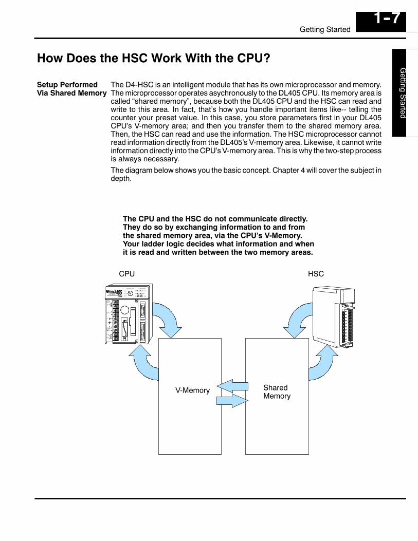
The D4-HSC is an intelligent module that has its own microprocessor and memory.The microprocessor operates asychronously to the DL405 CPU. Its memory area iscalled “shared memory”, because both the DL405 CPU and the HSC can read andwrite to this area. In fact, that’s how you handle important items like-- telling thecounter your preset value. In this case, you store parameters first in your DL405CPU’s V-memory area; and then you transfer them to the shared memory area.Then, the HSC can read and use the information. The HSC microprocessor cannotread information directly from the DL405’s V-memory area. Likewise, it cannot writeinformation directly into the CPU’s V-memory area. This is why the two-step processis always necessary.The diagram below shows you the basic concept. Chapter 4 will cover the subject indepth.
HSC
SharedMemory
V-Memory
CPU
The CPU and the HSC do not communicate directly.They do so by exchanging information to and fromthe shared memory area, via the CPU’s V-Memory.Your ladder logic decides what information and whenit is read and written between the two memory areas.
Setup PerformedVia Shared Memory
D4-
-HS
CG
ettin
gS
tarte
d1--8
Getting Started
Physical Characteristics & Specifications
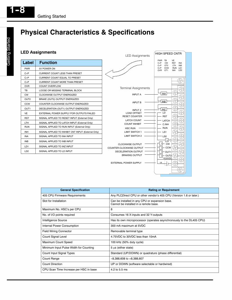
SIGNAL APPLIED TO INA INPUT
SIGNAL APPLIED TO INB INPUT
SIGNAL APPLIED TO INZ INPUT
SIGNAL APPLIED TO LD INPUT
5V POWER ON
LOOSE OR MISSING TERMINAL BLOCK
CURRENT COUNT LESS THAN PRESET
CURRENT COUNT EQUAL TO PRESET
CURRENT COUNT MORE THAN PRESET
COUNT OVERFLOW
CLOCKWISE OUTPUT ENERGIZED
COUNTER CLOCKWISE OUTPUT ENERGIZED
BRAKE (OUT2) OUTPUT ENERGIZED
DECELERATION (OUT1) OUTPUT ENERGIZED
SIGNAL APPLIED TO RESET INPUT (External Only)
SIGNAL APPLIED TO INHIBIT CNT INPUT (External Only)
INPUT A
INPUT B
INPUT ZLOAD OFFSET
RESET COUNTER
COUNT INHIBIT
HSC RUN
LIMIT SWITCH 1
LIMIT SWITCH 2
LATCH COUNT
CLOCKWISE OUTPUT
COUNTER-CLOCKWISE OUTPUT
DECELERATION OUTPUT
BRAKING OUTPUT
EXTERNAL POWER SUPPLY
SIGNAL APPLIED TO RUN INPUT (External Only)
SIGNAL APPLIED TO LATCH INPUT (External Only)
EXTERNAL POWER SUPPLY FOR OUTPUTS FAILED
PWRC<PC=PC>P
TBCWOT2CCW
HIGH SPEED CNTR
VERSTLTHRUN
INAINB
OT1 INHLD1LD2
INA
INB
INZ
--+V
LD
RST
LATCH
C.INH
RUN
LS1
LS2
L
L
L
L
CW
CCW
OUT1
OUT212/24VDC
1A
FunctionLabelPWR
C<P
C=P
C>P
OVR
TB
CW
OUT2
CCW
OUT1
VE
RST
LTH
RUN
INH
INA
INB
LD1
LD2
Terminal Assignments
LED Assignments
OVR
General Specification Rating or Requirement
405 CPU Firmware Requirements Any PLCDirect CPU or other vendor’s 405 CPU (Version 1.6 or later.)
Slot for Installation Can be installed in any CPU or expansion base.Cannot be installed in a remote base.
Maximum No. HSC’s per CPU 8
No. of I/O points required Consumes 16 X-inputs and 32 Y-outputs
Intelligence Source Has its own microprocessor (operates asynchronously to the DL405 CPU)
Internal Power Consumption 300 mA maximum at 5VDC
Field Wiring Connector Removable terminal type
Count Signal Level 4.75VDC to 30VDC less than 10mA
Maximum Count Speed 100 kHz (50% duty cycle)
Minimum Input Pulse Width for Counting 5 µs (either state)
Count Input Signal Types Standard (UP/DOWN) or quadrature (phase differential)
Count Range --8,388,608 to +8,388,607
Count Direction UP or DOWN (software selectable or hardwired)
CPU Scan Time Increase per HSC in base 4.2 to 5.5 ms
LED Assignments
D4--H
SC
Getting
Started
1--9Getting Started
Counting Inputs (INA, INB, INZ) Rating or Requirement
Input Voltage Range 4.75VDC to 30VDC
Maximum Input Current 10 mA
ON Voltage = 4.75VDC
ON Current = 5mA
OFF Voltage = 2.0VDC
OFF Current = 1.6mA
OFF to ON Delay = 1.2µs at 5VDC= 0.8µs at 12VDC= 0.5µs at 24VDC
ON to OFF Delay = 1.0µs at 5VDC= 1.2µs at 12VDC= 2.5µs at 24VDC
Control Inputs (LD, LATCH, RST, CINH, RUN, LS1 LS2) Rating or Requirement
Input Voltage Range 10.2VDC--26.4VDC
Maximum Input Current 10mA
ON Voltage =10.2VDC
ON Current =5mA (LD and LATCH); ²4.8mA (RST,CINH,RUN,LS1 and LS2)
OFF Voltage =4.6VDC (LD and LATCH);±5.6VDC (RST,CINH,RUN,LS1 and LS2)
OFF Current =1.6mA (LD and LATCH); ±2mA (RST,CINH,RUN,LS1 and LS2)
OFF to ON Delay =75µs at 12VDC (LD and LATCH)=82.5µs at 12VDC (RST,CINH,RUN,LS1 and LS2)=30µs at 24VDC (LD and LATCH)=37.5µs at 24VDC (RST,CINH,RUN,LS1 and LS2)
ON to OFF Delay =240µs at 12VDC (LD and LATCH)=105µs at 12VDC (RST,CINH,RUN LS1 and LS2)=260µs at 24VDC (LD and LATCH)=105µs at 24VDC (RST,CINH,RUN LS1 and LS2)
Control Outputs (CW,CCW,OUT1,OUT2) Rating or Requirement
Output Power Source External 10.2VDC--26.4VDC, 1A
Output Type Open Collector
Maximum Output Current 100 mA per point
Output ON Voltage Drop = 1.5VDC
Output OFF Leakage Current = 100µA
Output OFF to ON Delay = 22.5µs at 12VDC= 21µs at 24VDC
Output ON to OFF Delay = 210µs at 12VDC= 270µs at 24VDC
Built--In Protection Shut off when output driver IC=175_C (Recovers at 150_C)Shut off when short (>500mA) is detected (Recovers when short is removed)
Input-pulse-reaching-Preset to internal-signal-reaching-Output 1 Time Delay
110µs
D4-
-HS
CG
ettin
gS
tarte
d1--10
Getting Started
Overview of HSC Inputs and Outputs
PWRC<PC=PC>P
TBCWOT2CCW
HIGH SPEED CNTR
VERSTLTHRUN
INAINB
D4-HSC
OT1 INHLD1LD2
INA
INB
INZ
--+V
LD
RST
LATCH
C.INH
RUN
LS1
LS2
L
L
L
L
CW
CCW
OUT1
OUT2
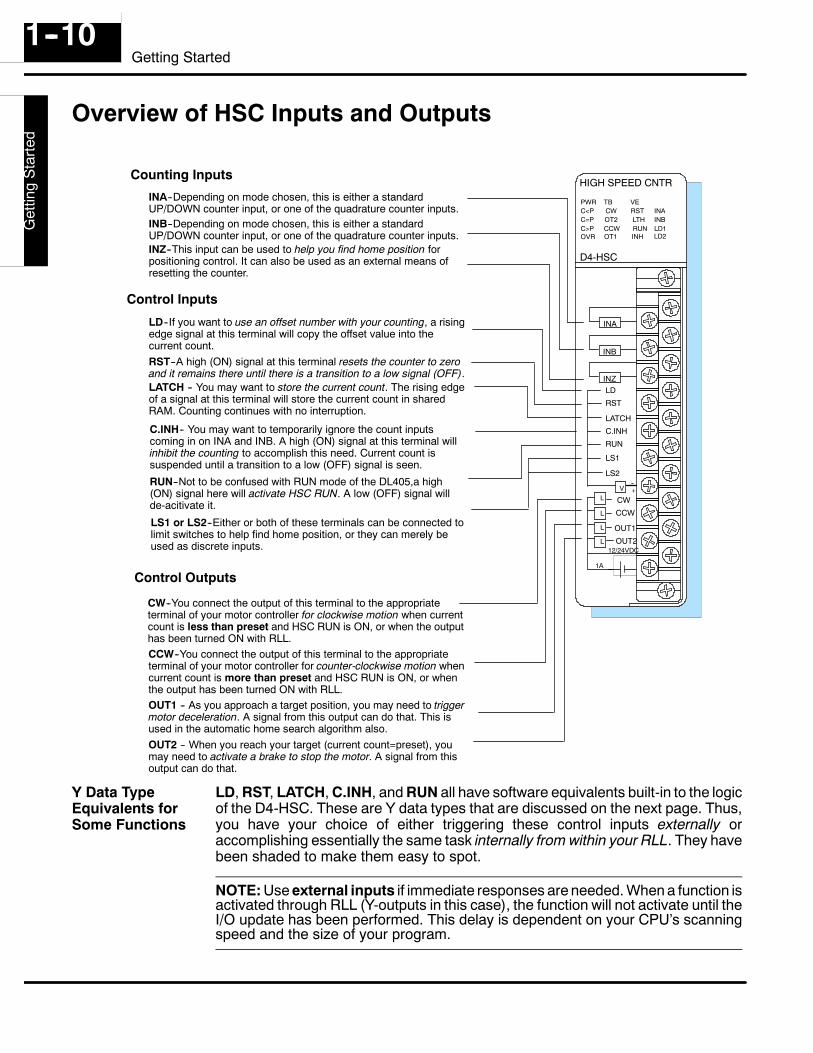
INA--Depending on mode chosen, this is either a standardUP/DOWN counter input, or one of the quadrature counter inputs.INB--Depending on mode chosen, this is either a standardUP/DOWN counter input, or one of the quadrature counter inputs.INZ--This input can be used to help you find home position forpositioning control. It can also be used as an external means ofresetting the counter.
LD--If you want to use an offset number with your counting, a risingedge signal at this terminal will copy the offset value into thecurrent count.RST--A high (ON) signal at this terminal resets the counter to zeroand it remains there until there is a transition to a low signal (OFF).LATCH -- You may want to store the current count. The rising edgeof a signal at this terminal will store the current count in sharedRAM. Counting continues with no interruption.
12/24VDC
1A
C.INH-- You may want to temporarily ignore the count inputscoming in on INA and INB. A high (ON) signal at this terminal willinhibit the counting to accomplish this need. Current count issuspended until a transition to a low (OFF) signal is seen.
RUN--Not to be confused with RUN mode of the DL405,a high(ON) signal here will activate HSC RUN. A low (OFF) signal willde-acitivate it.
LS1 or LS2--Either or both of these terminals can be connected tolimit switches to help find home position, or they can merely beused as discrete inputs.
CW--You connect the output of this terminal to the appropriateterminal of your motor controller for clockwise motion when currentcount is less than preset and HSC RUN is ON, or when the outputhas been turned ON with RLL.CCW--You connect the output of this terminal to the appropriateterminal of your motor controller for counter-clockwise motion whencurrent count is more than preset and HSC RUN is ON, or whenthe output has been turned ON with RLL.OUT1 -- As you approach a target position, you may need to triggermotor deceleration. A signal from this output can do that. This isused in the automatic home search algorithm also.OUT2 -- When you reach your target (current count=preset), youmay need to activate a brake to stop the motor. A signal from thisoutput can do that.
Counting Inputs
Control Inputs
Control Outputs
OVR
LD, RST, LATCH, C.INH, and RUN all have software equivalents built-in to the logicof the D4-HSC. These are Y data types that are discussed on the next page. Thus,you have your choice of either triggering these control inputs externally oraccomplishing essentially the same task internally from within your RLL. They havebeen shaded to make them easy to spot.
NOTE: Use external inputs if immediate responses are needed. When a function isactivated through RLL (Y-outputs in this case), the function will not activate until theI/O update has been performed. This delay is dependent on your CPU’s scanningspeed and the size of your program.
Y Data TypeEquivalents forSome Functions
D4--H
SC
Getting
Started
1--11Getting Started
X Input and Y Output Assignments
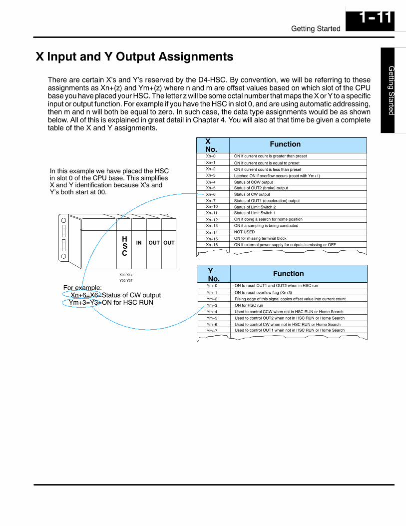
There are certain X’s and Y’s reserved by the D4-HSC. By convention, we will be referring to theseassignments as Xn+(z) and Ym+(z) where n and m are offset values based on which slot of the CPUbase you have placed your HSC. The letter z will be some octal number that maps the X or Y to a specificinput or output function. For example if you have the HSC in slot 0, and are using automatic addressing,then m and n will both be equal to zero. In such case, the data type assignments would be as shownbelow. All of this is explained in great detail in Chapter 4. You will also at that time be given a completetable of the X and Y assignments.
XNo.
Function
FunctionYNo.
Xn+0
Xn+1
Xn+2
Xn+3
Xn+4Xn+5
Xn+6
Xn+7Xn+10
Xn+11
Xn+12Xn+13
Xn+14
Xn+15Xn+16
ON if current count is greater than preset
ON if current count is equal to preset
ON if current count is less than preset
Latched ON if overflow occurs (reset with Ym+1)
Status of CCW outputStatus of OUT2 (brake) output
Status of CW output
Status of OUT1 (deceleration) output
Status of Limit Switch 2Status of Limit Switch 1
ON if doing a search for home position
ON if a sampling is being conducted
NOT USED
ON for missing terminal block
ON if external power supply for outputs is missing or OFF
Ym+0
Ym+1
Ym+2
Ym+3
Ym+4
Ym+5
Ym+6
Ym+7
ON to reset OUT1 and OUT2 when in HSC run
ON to reset overflow flag (Xn+3)
Rising edge of this signal copies offset value into current count
ON for HSC run
Used to control CCW when not in HSC RUN or Home Search
Used to control OUT2 when not in HSC RUN or Home Search
Used to control CW when not in HSC RUN or Home SearchUsed to control OUT1 when not in HSC RUN or Home Search
IN OUT OUTHSC
X00-X17
Y00-Y37
In this example we have placed the HSCin slot 0 of the CPU base. This simplifiesX and Y identification because X’s andY’s both start at 00.
For example:Xn+6=X6=Status of CW outputYm+3=Y3=ON for HSC RUN
D4-
-HS
CG
ettin
gS
tarte
d1--12
Getting Started
Putting It All Together
Up to this point, we have given you only the very basic information about the HSCmodule. The six chapters that follow will give you the additional information you needto make full use of the HSC. There are five basic steps for using the HSC.
Document Install the Module and Connect the Wiring — Chapter TwoDocument Understand How the Module Maps into the I/O Points, andHow the Setup Information is Stored — Chapter ThreeDocument Setup the Counting and Control Input Parameters —Chapter FourDocument Setup the Control Outputs — Chapter FiveDocument Setup Any Special Features, Such as Home Search orSampling — Chapter Six
The next chapter will walk you through the installation and wiring before moving youon to Step 2.
Five Steps forUsing the HSC
The Next Chapter
12Installation & Wiring
In This Chapter. . . .— How to install the D4-HSC— Connecting the Wiring— Connecting the Power Supply— Count Input Wiring Diagram— Control Input Wiring Diagram— Control Output Wiring Diagram
D4-
-HS
CIn
stal
latio
nan
dW
iring
Inst
alla
tion
and
Saf
ety
Gui
delin
es2--2
Installation and Wiring for the D4--HSC
How to Install the D4-HSC
WARNING: To minimize the risk of electrical shock, personal injury, orequipment damage, always disconnect the system power before installing orremoving any system component.
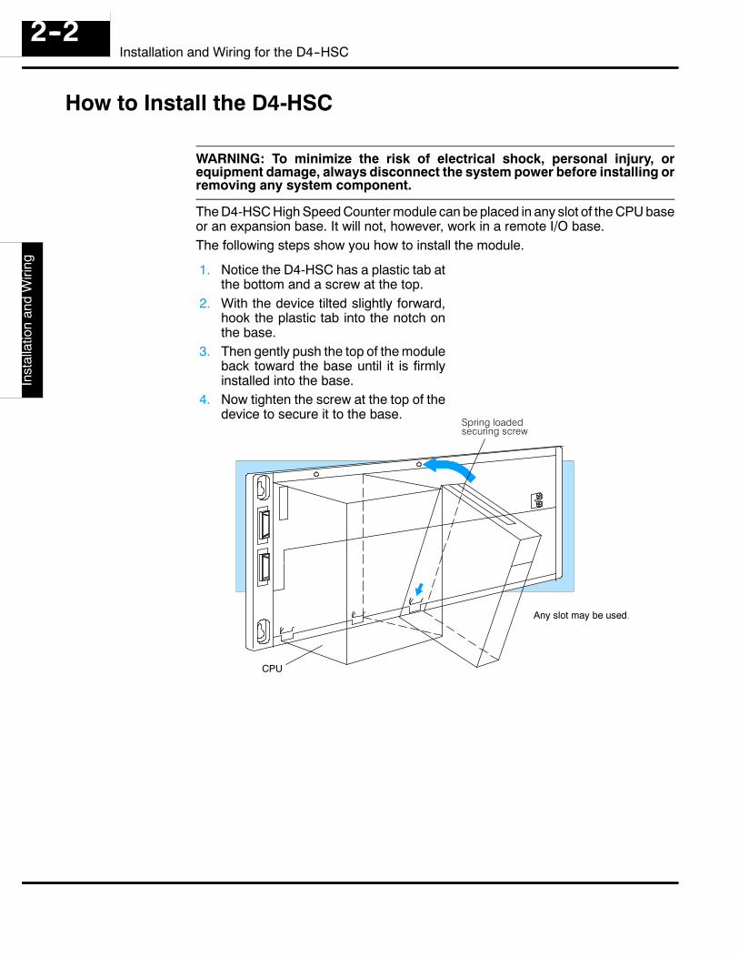
The D4-HSC High Speed Counter module can be placed in any slot of the CPU baseor an expansion base. It will not, however, work in a remote I/O base.The following steps show you how to install the module.
1. Notice the D4-HSC has a plastic tab atthe bottom and a screw at the top.
2. With the device tilted slightly forward,hook the plastic tab into the notch onthe base.
3. Then gently push the top of the moduleback toward the base until it is firmlyinstalled into the base.
4. Now tighten the screw at the top of thedevice to secure it to the base.
Spring loadedsecuring screw
Any slot may be used.
CPU
D4--H
SC
Installationand
Wiring
Installationand
Safety
Guidelines
2--3Installation and Wiring for the D4--HSC
Connecting the Wiring
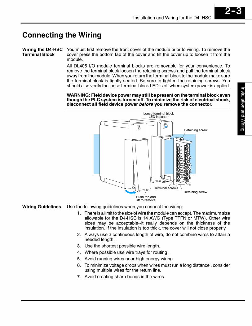
You must first remove the front cover of the module prior to wiring. To remove thecover press the bottom tab of the cover and tilt the cover up to loosen it from themodule.All DL405 I/O module terminal blocks are removable for your convenience. Toremove the terminal block loosen the retaining screws and pull the terminal blockaway from the module. When you return the terminal block to the module make surethe terminal block is tightly seated. Be sure to tighten the retaining screws. Youshould also verify the loose terminal block LED is off when system power is applied.
WARNING: Field device power may still be present on the terminal block eventhough the PLC system is turned off. To minimize the risk of electrical shock,disconnect all field device power before you remove the connector.
Push tab andlift to remove
Retaining screwTerminal screws
Retaining screw
Loose terminal blockLED indicator
Use the following guidelines when you connect the wiring:1. There is a limit to the size of wire the module can accept. The maximum size
allowable for the D4-HSC is 14 AWG (Type TFFN or MTW). Other wiresizes may be acceptable--it really depends on the thickness of theinsulation. If the insulation is too thick, the cover will not close properly.
2. Always use a continuous length of wire, do not combine wires to attain aneeded length.
3. Use the shortest possible wire length.4. Where possible use wire trays for routing .5. Avoid running wires near high energy wiring.6. To minimize voltage drops when wires must run a long distance , consider
using multiple wires for the return line.7. Avoid creating sharp bends in the wires.
Wiring the D4-HSCTerminal Block
Wiring Guidelines
D4-
-HS
CIn
stal
latio
nan
dW
iring
Inst
alla
tion
and
Saf
ety
Gui
delin
es2--4
Installation and Wiring for the D4--HSC
Connecting the Power Supply
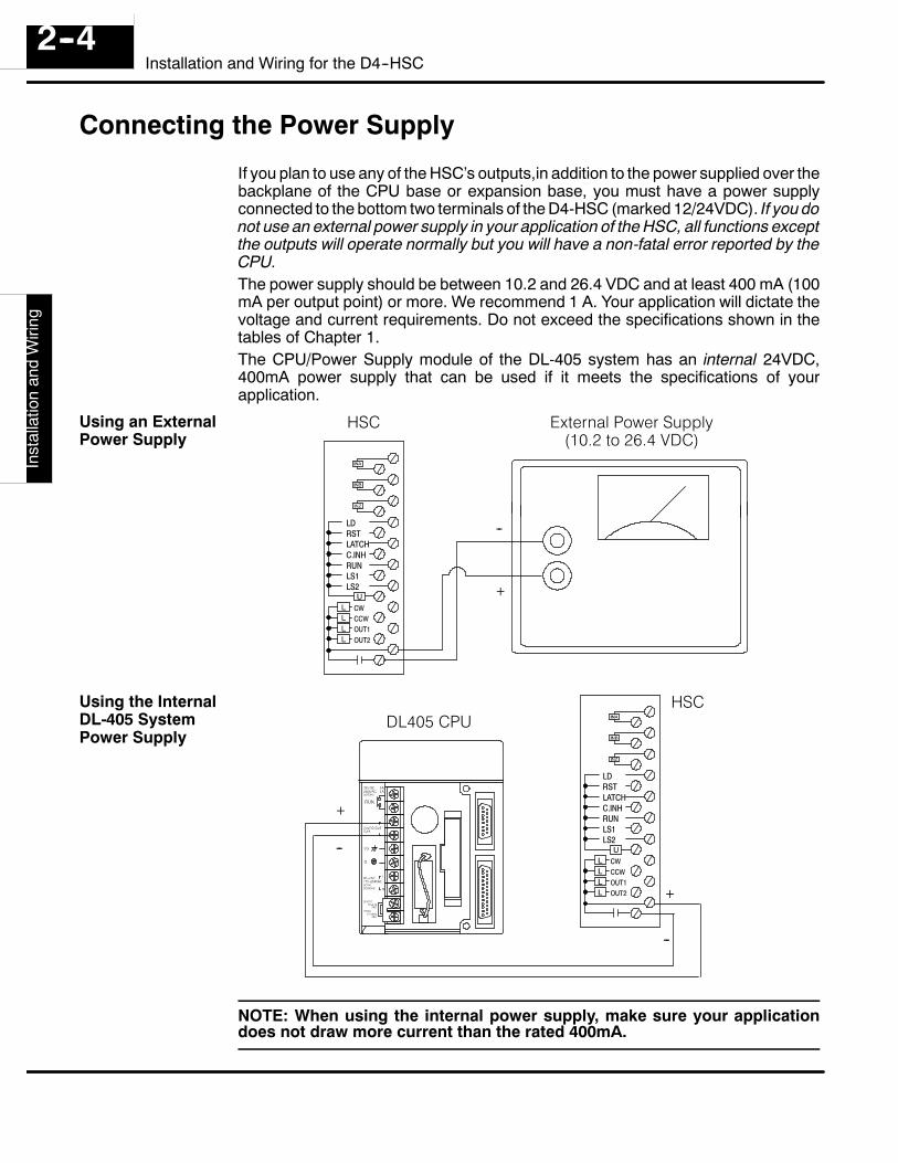
If you plan to use any of the HSC’s outputs,in addition to the power supplied over thebackplane of the CPU base or expansion base, you must have a power supplyconnected to the bottom two terminals of the D4-HSC (marked 12/24VDC). If you donot use an external power supply in your application of the HSC, all functions exceptthe outputs will operate normally but you will have a non-fatal error reported by theCPU.The power supply should be between 10.2 and 26.4 VDC and at least 400 mA (100mA per output point) or more. We recommend 1 A. Your application will dictate thevoltage and current requirements. Do not exceed the specifications shown in thetables of Chapter 1.The CPU/Power Supply module of the DL-405 system has an internal 24VDC,400mA power supply that can be used if it meets the specifications of yourapplication.
LDRSTLATCHC.INHRUNLS1LS2
CWCCWOUT1OUT2
HSC External Power Supply(10.2 to 26.4 VDC)
+
--
LDRSTLATCHC.INHRUNLS1LS2
CWCCWOUT1OUT2
HSCDL405 CPU
+
--
+
--
NOTE: When using the internal power supply, make sure your applicationdoes not draw more current than the rated 400mA.
Using an ExternalPower Supply
Using the InternalDL-405 SystemPower Supply
D4--H
SC
Installationand
Wiring
Installationand
Safety
Guidelines
2--5Installation and Wiring for the D4--HSC
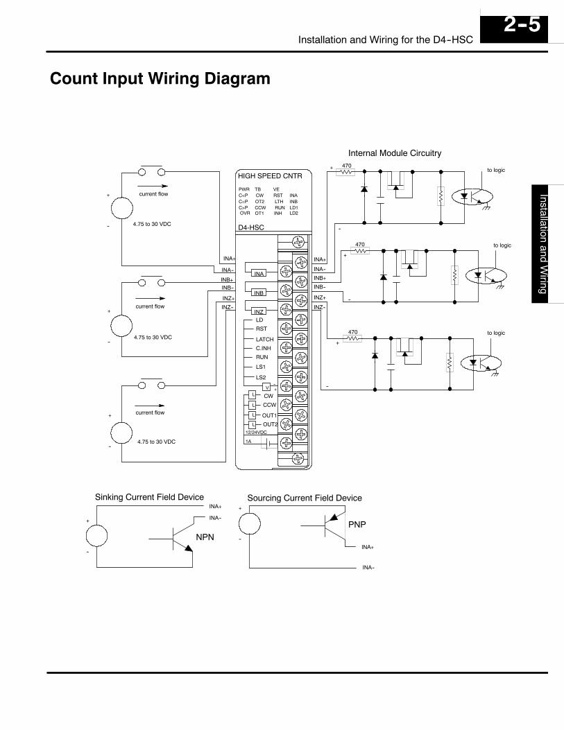
Count Input Wiring Diagram
PWRC<PC=PC>P
TBCWOT2CCW
HIGH SPEED CNTR
VERSTLTHRUN
INAINB
OVR
D4-HSC
OT1 INHLD1LD2
INA
INB
INZ
--+V
LD
RST
LATCH
C.INH
RUN
LS1
LS2
L
L
L
L
CW
CCW
OUT1
OUT212/24VDC
1A
INA+
INA--
INB+
INB--
INZ+
INZ--
+
--
+INA+
INA--
INB+INB--
INZ+
INZ--
+
--
+
--
+
--
to logic
to logic
to logic
current flow
current flow
current flow
4.75 to 30 VDC
4.75 to 30 VDC
4.75 to 30 VDC
+
--
Sinking Current Field Device
NPN
+
--
Sourcing Current Field Device
PNP
INA+
INA--
INA+
INA--
+
Internal Module Circuitry470
470
470
--
--
D4-
-HS
CIn
stal
latio
nan
dW
iring
Inst
alla
tion
and
Saf
ety
Gui
delin
es2--6
Installation and Wiring for the D4--HSC
Control Input Wiring Diagram
PWRC<PC=PC>P
TBCWOT2CCW
HIGH SPEED CNTR
VERSTLTHRUN
INAINB
OVR
D4-HSC
OT1 INHLD1LD2
INA
INB
INZ
--+V
LD
RST
LATCH
C.INH
RUN
LS1
LS2
L
L
L
L
CW
CCW
OUT1
OUT212/24VDC
1A
To logic
To logic
To logic
To logic
To logic
To logic
To logic
2.7K
2.7K
2.7K
2.7K
2.7K
2.7K
2.7K
+
--
+
--
LD
RST
LATCH
C. INH
RUNLS1
LS2common
common
LD
RSTLATCH
C. INH
RUNLS1
LS2
Field Circuitry
Internal Circuitry.
10.2 --26.4 VDC
Isolation Barrier
Note: Dashes indicate alternate wiring.
D4--H
SC
Installationand
Wiring
Installationand
Safety
Guidelines
2--7Installation and Wiring for the D4--HSC
Control Output Wiring Diagram
PWRC<PC=PC>P
TBCWOT2CCW
HIGH SPEED CNTR
VERSTLTHRUN
INAINB
OVR
D4-HSC
OT1 INHLD1LD2
INA
INB
INZ
--+V
LD
RST
LATCH
C.INH
RUN
LS1
LS2
L
L
L
L
CW
CCW
OUT1
OUT212/24VDC
1A
CWCCW
OUT1
OUT2
V(outputs)
RTN
Internal Circuitry External Circuitry
CWCCW
OUT1
OUT2
V(outputs)
RTN
Load
Load
Load
Load
+
--
to logic
to logic
to logic
to logic
10.2 -- 26.4 VDC
Only required ifusing outputs
13Understanding theOperation
In This Chapter. . . .— The Operating Basics— Assigning Your Data Types— Using the X and Y Assignment Table— Reading and Writing Shared Memory— Understanding How Numbers are Stored
Get
ting
Sta
rted
Use
rApp
licat
ion
Gui
delin
esD
4--H
SC
Und
erst
andi
ngO
pera
tion
3--2Understanding the Operation of the HSC
The Operating Basics
Although most readers of this manual will have had prior experience with the PLCand its various modules, there are some unique features belonging to the HSC, ofwhich you must become familiar. These include:
S How the HSC reserves X (inputs) and Y (outputs).S The X and Y assignment table of the HSCS The concept of shared memory and its relation to V-memoryS Reading and writing data to shared memoryS How numbers are stored in shared memory
The pages that follow in this chapter will tell you in detail how all of the aboveoperations are handled.
UserA
pplicationG
uidelinesD
4--HS
CU
nderstandingO
peration3--3
Understanding the Operation of the HSC
Assigning Your Data Types
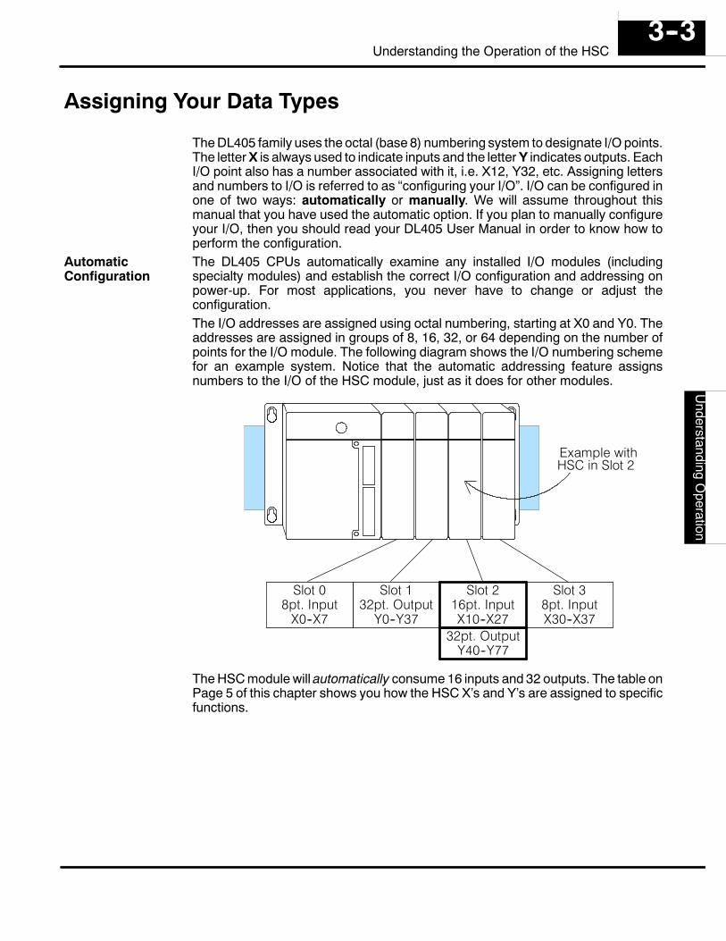
The DL405 family uses the octal (base 8) numbering system to designate I/O points.The letter X is always used to indicate inputs and the letter Y indicates outputs. EachI/O point also has a number associated with it, i.e. X12, Y32, etc. Assigning lettersand numbers to I/O is referred to as “configuring your I/O”. I/O can be configured inone of two ways: automatically or manually. We will assume throughout thismanual that you have used the automatic option. If you plan to manually configureyour I/O, then you should read your DL405 User Manual in order to know how toperform the configuration.The DL405 CPUs automatically examine any installed I/O modules (includingspecialty modules) and establish the correct I/O configuration and addressing onpower-up. For most applications, you never have to change or adjust theconfiguration.The I/O addresses are assigned using octal numbering, starting at X0 and Y0. Theaddresses are assigned in groups of 8, 16, 32, or 64 depending on the number ofpoints for the I/O module. The following diagram shows the I/O numbering schemefor an example system. Notice that the automatic addressing feature assignsnumbers to the I/O of the HSC module, just as it does for other modules.
Slot 08pt. Input
X0--X7
Slot 132pt. Output
Y0--Y37
Slot 216pt. InputX10--X27
Slot 38pt. InputX30--X37
HSC in Slot 2
32pt. OutputY40--Y77
Example with
The HSC module will automatically consume 16 inputs and 32 outputs. The table onPage 5 of this chapter shows you how the HSC X’s and Y’s are assigned to specificfunctions.
AutomaticConfiguration
Get
ting
Sta
rted
Use
rApp
licat
ion
Gui
delin
esD
4--H
SC
Und
erst
andi
ngO
pera
tion
3--4Understanding the Operation of the HSC
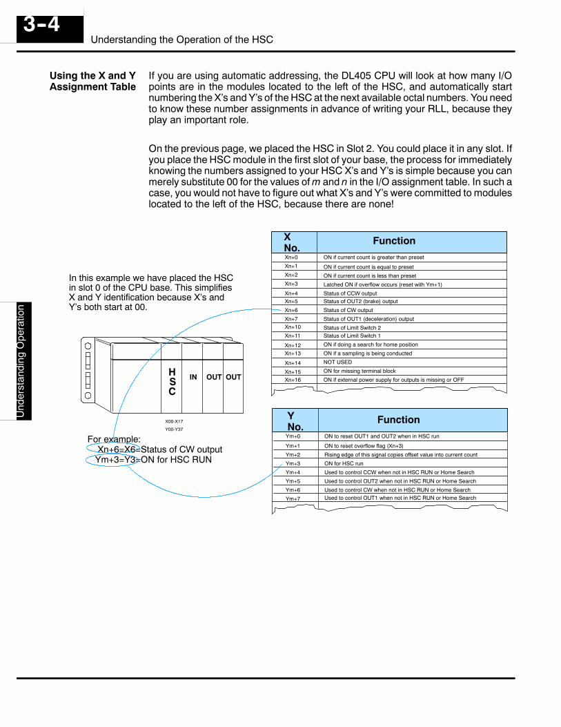
If you are using automatic addressing, the DL405 CPU will look at how many I/Opoints are in the modules located to the left of the HSC, and automatically startnumbering the X’s and Y’s of the HSC at the next available octal numbers. You needto know these number assignments in advance of writing your RLL, because theyplay an important role.
On the previous page, we placed the HSC in Slot 2. You could place it in any slot. Ifyou place the HSC module in the first slot of your base, the process for immediatelyknowing the numbers assigned to your HSC X’s and Y’s is simple because you canmerely substitute 00 for the values of m and n in the I/O assignment table. In such acase, you would not have to figure out what X’s and Y’s were committed to moduleslocated to the left of the HSC, because there are none!
XNo.
Function
FunctionYNo.
Xn+0
Xn+1
Xn+2
Xn+3
Xn+4Xn+5
Xn+6
Xn+7Xn+10
Xn+11
Xn+12Xn+13
Xn+14
Xn+15Xn+16
ON if current count is greater than preset
ON if current count is equal to preset
ON if current count is less than preset
Latched ON if overflow occurs (reset with Ym+1)
Status of CCW outputStatus of OUT2 (brake) output
Status of CW output
Status of OUT1 (deceleration) output
Status of Limit Switch 2Status of Limit Switch 1
ON if doing a search for home position
ON if a sampling is being conducted
NOT USED
ON for missing terminal block
ON if external power supply for outputs is missing or OFF
Ym+0
Ym+1
Ym+2
Ym+3
Ym+4
Ym+5
Ym+6
Ym+7
ON to reset OUT1 and OUT2 when in HSC run
ON to reset overflow flag (Xn+3)
Rising edge of this signal copies offset value into current count
ON for HSC run
Used to control CCW when not in HSC RUN or Home Search
Used to control OUT2 when not in HSC RUN or Home Search
Used to control CW when not in HSC RUN or Home SearchUsed to control OUT1 when not in HSC RUN or Home Search
IN OUT OUTHSC
X00-X17
Y00-Y37
In this example we have placed the HSCin slot 0 of the CPU base. This simplifiesX and Y identification because X’s andY’s both start at 00.
For example:Xn+6=X6=Status of CW outputYm+3=Y3=ON for HSC RUN
Using the X and YAssignment Table
UserA
pplicationG
uidelinesD
4--HS
CU
nderstandingO
peration3--5
Understanding the Operation of the HSC
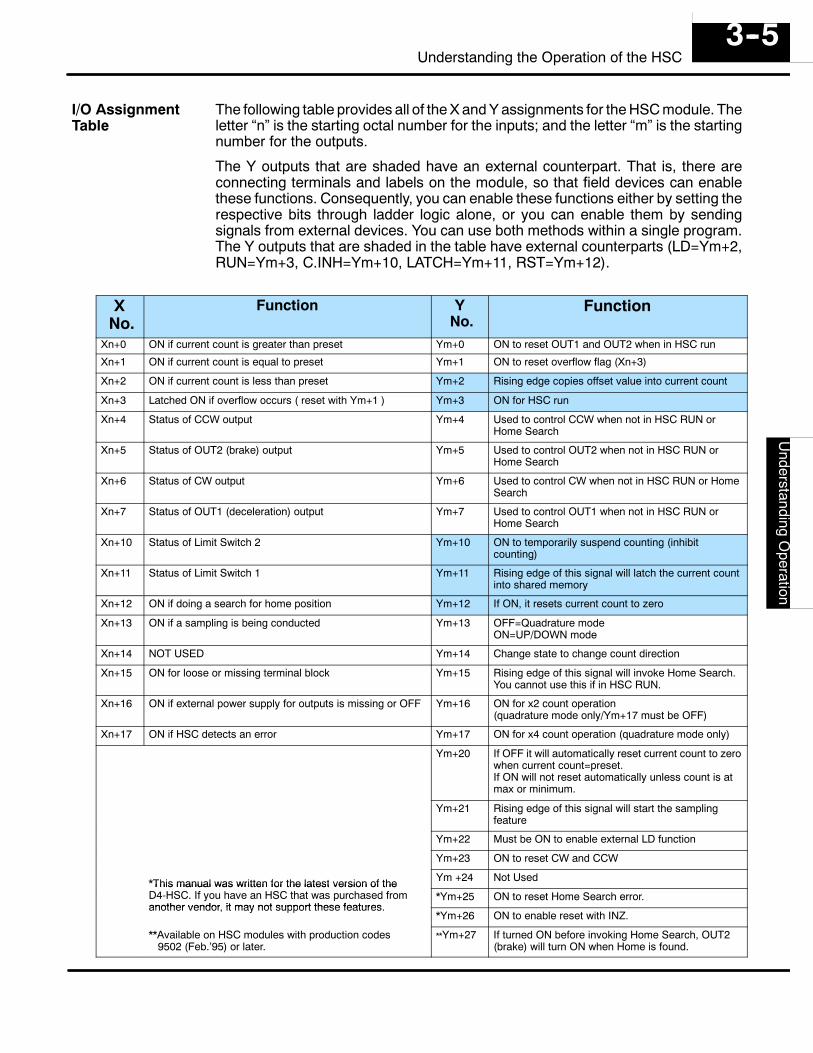
The following table provides all of the X and Y assignments for the HSC module. Theletter “n” is the starting octal number for the inputs; and the letter “m” is the startingnumber for the outputs.
The Y outputs that are shaded have an external counterpart. That is, there areconnecting terminals and labels on the module, so that field devices can enablethese functions. Consequently, you can enable these functions either by setting therespective bits through ladder logic alone, or you can enable them by sendingsignals from external devices. You can use both methods within a single program.The Y outputs that are shaded in the table have external counterparts (LD=Ym+2,RUN=Ym+3, C.INH=Ym+10, LATCH=Ym+11, RST=Ym+12).
XNo.
Function YNo.
Function
Xn+0 ON if current count is greater than preset Ym+0 ON to reset OUT1 and OUT2 when in HSC run
Xn+1 ON if current count is equal to preset Ym+1 ON to reset overflow flag (Xn+3)
Xn+2 ON if current count is less than preset Ym+2 Rising edge copies offset value into current count
Xn+3 Latched ON if overflow occurs ( reset with Ym+1 ) Ym+3 ON for HSC run
Xn+4 Status of CCW output Ym+4 Used to control CCW when not in HSC RUN orHome Search
Xn+5 Status of OUT2 (brake) output Ym+5 Used to control OUT2 when not in HSC RUN orHome Search
Xn+6 Status of CW output Ym+6 Used to control CW when not in HSC RUN or HomeSearch
Xn+7 Status of OUT1 (deceleration) output Ym+7 Used to control OUT1 when not in HSC RUN orHome Search
Xn+10 Status of Limit Switch 2 Ym+10 ON to temporarily suspend counting (inhibitcounting)
Xn+11 Status of Limit Switch 1 Ym+11 Rising edge of this signal will latch the current countinto shared memory
Xn+12 ON if doing a search for home position Ym+12 If ON, it resets current count to zero
Xn+13 ON if a sampling is being conducted Ym+13 OFF=Quadrature modeON=UP/DOWN mode
Xn+14 NOT USED Ym+14 Change state to change count direction
Xn+15 ON for loose or missing terminal block Ym+15 Rising edge of this signal will invoke Home Search.You cannot use this if in HSC RUN.
Xn+16 ON if external power supply for outputs is missing or OFF Ym+16 ON for x2 count operation(quadrature mode only/Ym+17 must be OFF)
Xn+17 ON if HSC detects an error Ym+17 ON for x4 count operation (quadrature mode only)
Ym+20 If OFF it will automatically reset current count to zerowhen current count=preset.If ON will not reset automatically unless count is atmax or minimum.
Ym+21 Rising edge of this signal will start the samplingfeature
Ym+22 Must be ON to enable external LD function
Ym+23 ON to reset CW and CCW
*This manual was written for the latest version of the Ym +24 Not Used*This manual was written for the latest version of theD4-HSC. If you have an HSC that was purchased fromanother vendor, it may not support these features.
*Ym+25 ON to reset Home Search error.another vendor, it may not support these features.
*Ym+26 ON to enable reset with INZ.
**Available on HSC modules with production codes9502 (Feb.’95) or later.
**Ym+27 If turned ON before invoking Home Search, OUT2(brake) will turn ON when Home is found.
I/O AssignmentTable
Get
ting
Sta
rted
Use
rApp
licat
ion
Gui
delin
esD
4--H
SC
Und
erst
andi
ngO
pera
tion
3--6Understanding the Operation of the HSC
Reading and Writing Shared Memory
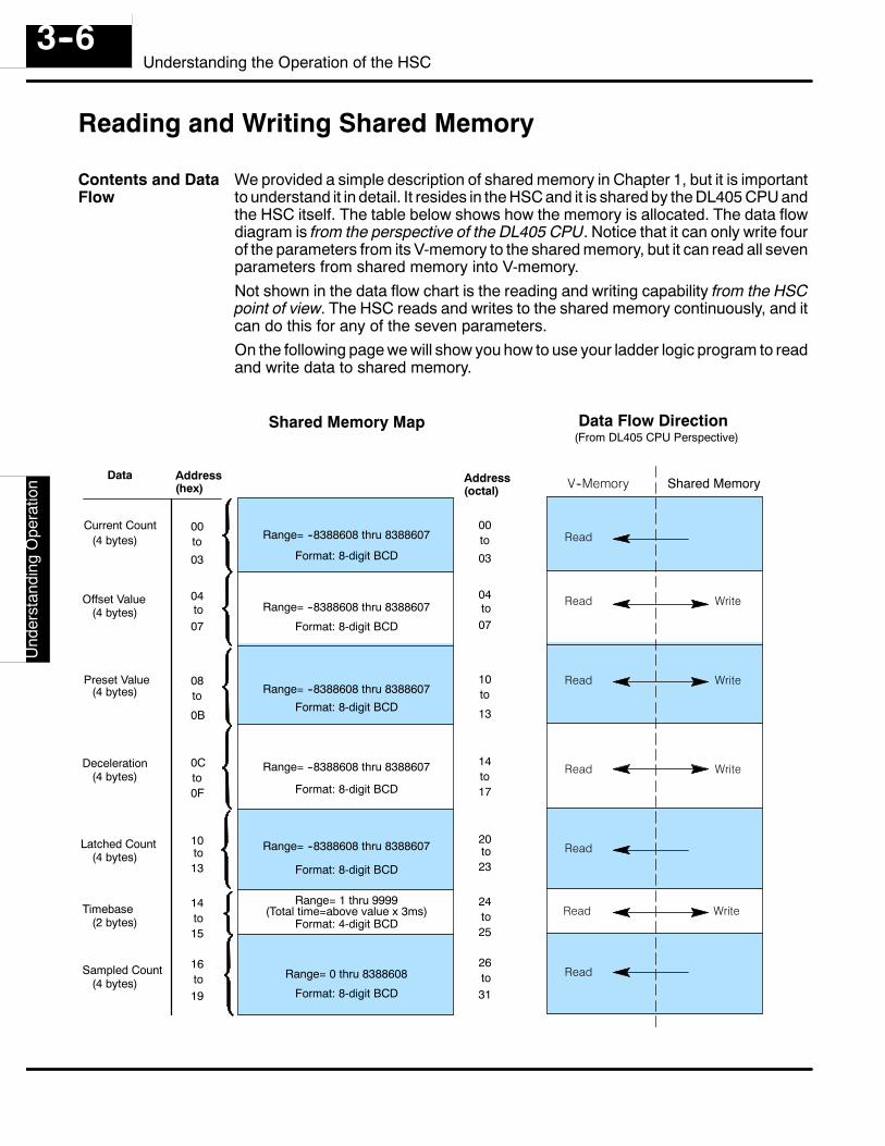
We provided a simple description of shared memory in Chapter 1, but it is importantto understand it in detail. It resides in the HSC and it is shared by the DL405 CPU andthe HSC itself. The table below shows how the memory is allocated. The data flowdiagram is from the perspective of the DL405 CPU. Notice that it can only write fourof the parameters from its V-memory to the shared memory, but it can read all sevenparameters from shared memory into V-memory.Not shown in the data flow chart is the reading and writing capability from the HSCpoint of view. The HSC reads and writes to the shared memory continuously, and itcan do this for any of the seven parameters.On the following page we will show you how to use your ladder logic program to readand write data to shared memory.
Current Count
Offset Value
Preset Value
Deceleration
Latched Count
Sampled Count
Timebase
Shared Memory Map Data Flow Direction
Read
Read Write
Read
Read
Read Write
Read Write
Read Write
Address(hex)
Data
00
04
08
0C
10
14
16
(4 bytes)
(4 bytes)
(4 bytes)
(4 bytes)
(4 bytes)
(4 bytes)
(2 bytes)
Range= --8388608 thru 8388607
Range= --8388608 thru 8388607
Range= --8388608 thru 8388607
Range= --8388608 thru 8388607
Range= --8388608 thru 8388607
Range= 0 thru 8388608
Format: 8-digit BCD
Range= 1 thru 9999
Format: 8-digit BCD
Format: 8-digit BCD
Format: 8-digit BCD
Format: 8-digit BCD
Format: 8-digit BCD
Format: 4-digit BCD(Total time=above value x 3ms)
V--Memory Shared Memory
(From DL405 CPU Perspective)
to03
to07
to
0B
to0F
to13
to15
to19
Address(octal)
00
04
10
14
20
24
26
to03
to07
to
13
to17
to23
to25
to31
Contents and DataFlow
UserA
pplicationG
uidelinesD
4--HS
CU
nderstandingO
peration3--7
Understanding the Operation of the HSC
NOTE: In the vast majority of cases, you will use your RLL program toexchange data between the CPU and the HSC. However, if you have ahandheld programmer, you can use AUX 47 to read and write shared memory.This can be helpful in some troubleshooting or startup situations. There areno commands available in DirectSOFT at this time to directly write data toshared memory.
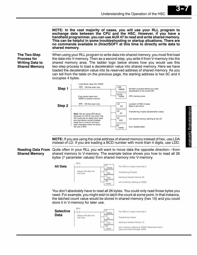
When using your RLL program to write data into shared memory, you must first loadthe data into V-memory. Then as a second step, you write it from V-memory into theshared memory area. The ladder logic below shows how you would use thistwo-step process to load a deceleration value into shared memory. Here we haveloaded the deceleration value into its reserved address of shared memory. As youcan tell from the table on the previous page, the starting address is hex 0C and itoccupies 4 bytes.
SP0
Copy decel value fromV2000 to shared memory
K4
WT
LDK0C
V2000
SP0
Load decel value into V2000
OUTDV2000
LDDK6000
LDK3
LD
Location of HSC in base:Base 0 and slot 3
Transferring 4 bytes (deceleration value)
into shared memory starting at hex 0C
from V2000/V2001
Number of pulses before you wantdeceleration to be turned ON
CPU memory area
ON first scan only
ON first scan only
Step 1
Step 2
Note: We are using SP0 abovebecause it is ON for one scan only.We could just as easily have usedany permissive contact instead.Keep this in mind for all futurelogic examples where we showthe use of SP0.
NOTE: If you are using the octal address of shared memory instead of hex, use LDAinstead of LD. If you are loading a BCD number with more than 4 digits, use LDD.
Quite often in your RLL you will want to move data the opposite direction----fromshared memory to V-memory. The example below shows you how to read all 26bytes (7 parameter values) from shared memory into V-memory.
SP01LD
K0003
LDK26
RDV3000
LDK00
The HSC is in base 0 and slot 3
Transferring 26 bytes
starting at shared memory 00
into V-memory starting at V3000
All DataAlways ON after thefirst scan
You don’t absolutely have to read all 26 bytes. You could only read those bytes youneed. For example, you might wish to latch the count at some point. In that instance,the latched count value would be stored in shared memory (hex 10) and you couldstore it in V-memory for later use.
SP01LD
K0003
LDK4
RDV2000
LDK10
The HSC is in base 0 and slot 3
Transferring 4 bytes
starting at shared memory 10
into V-memory starting at V2000. Remember that 4bytes will extend through V2001.
SelectiveData Always ON after the
first scan
The Two-StepProcess forWriting Data toShared Memory
Reading Data FromShared Memory
Get
ting
Sta
rted
Use
rApp
licat
ion
Gui
delin
esD
4--H
SC
Und
erst
andi
ngO
pera
tion
3--8Understanding the Operation of the HSC
Understanding How Numbers areStored In Shared Memory
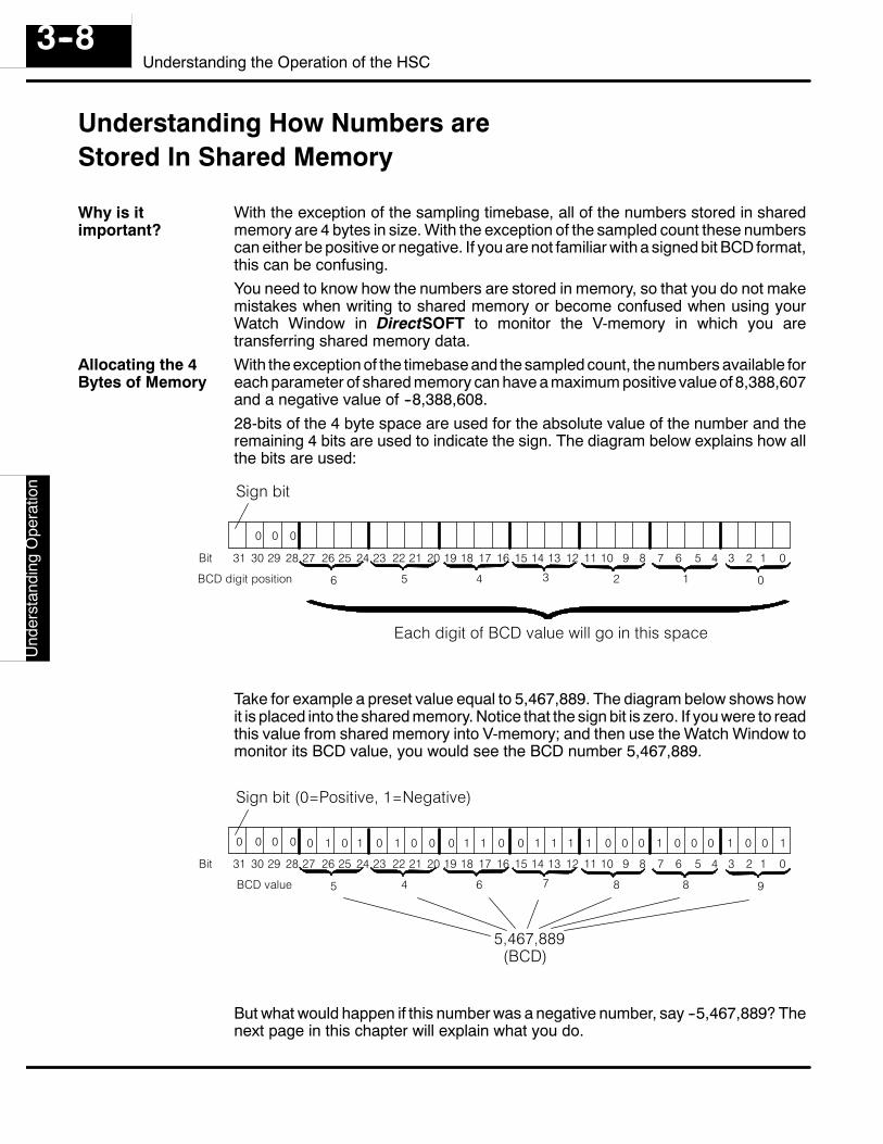
With the exception of the sampling timebase, all of the numbers stored in sharedmemory are 4 bytes in size. With the exception of the sampled count these numberscan either be positive or negative. If you are not familiar with a signed bit BCD format,this can be confusing.You need to know how the numbers are stored in memory, so that you do not makemistakes when writing to shared memory or become confused when using yourWatch Window in DirectSOFT to monitor the V-memory in which you aretransferring shared memory data.With the exception of the timebase and the sampled count, the numbers available foreach parameter of shared memory can have a maximum positive value of 8,388,607and a negative value of --8,388,608.28-bits of the 4 byte space are used for the absolute value of the number and theremaining 4 bits are used to indicate the sign. The diagram below explains how allthe bits are used:
12345678910 012131415161718192021 11232425262728293031 22
0 0 0
Bit
Sign bit
0123456BCD digit position
Each digit of BCD value will go in this space
Take for example a preset value equal to 5,467,889. The diagram below shows howit is placed into the shared memory. Notice that the sign bit is zero. If you were to readthis value from shared memory into V-memory; and then use the Watch Window tomonitor its BCD value, you would see the BCD number 5,467,889.
12345678910 012131415161718192021 11232425262728293031 22
0 0 0
Bit
Sign bit (0=Positive, 1=Negative)
9887645BCD value
5,467,889(BCD)
0 1 10 011 0 000 00111001101 0 0011 00
But what would happen if this number was a negative number, say --5,467,889? Thenext page in this chapter will explain what you do.
Why is itimportant?
Allocating the 4Bytes of Memory
UserA
pplicationG
uidelinesD
4--HS
CU
nderstandingO
peration3--9
Understanding the Operation of the HSC
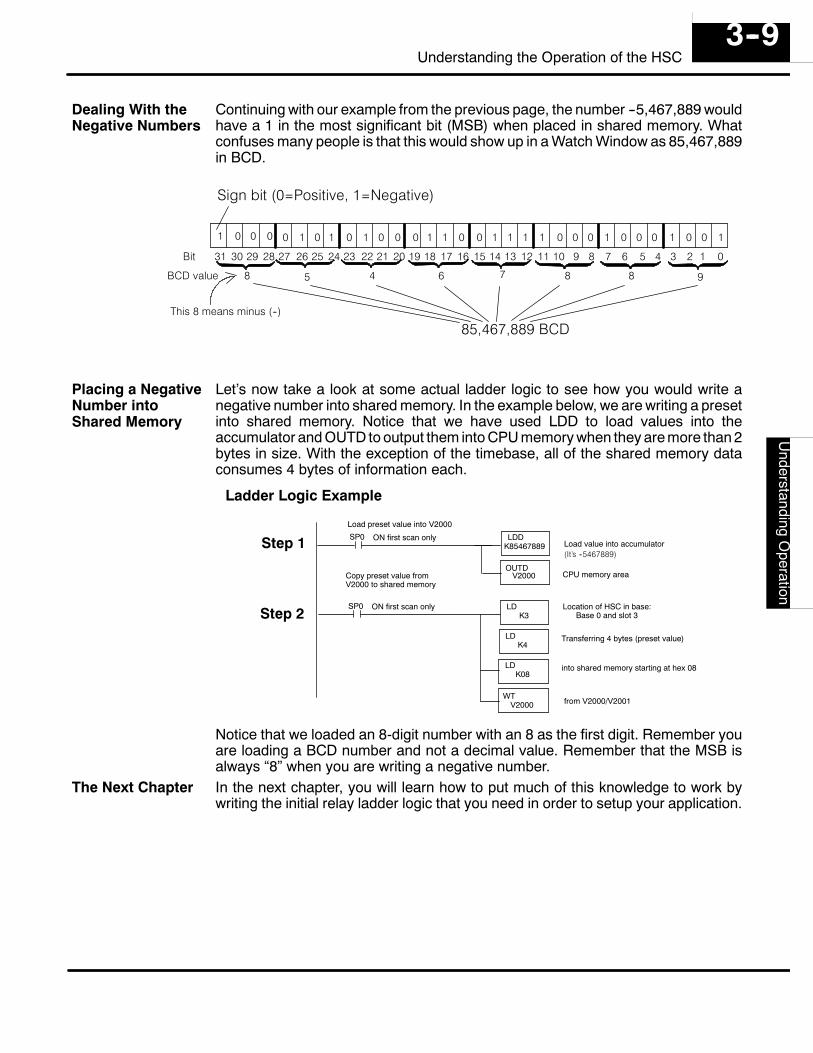
Continuing with our example from the previous page, the number --5,467,889 wouldhave a 1 in the most significant bit (MSB) when placed in shared memory. Whatconfuses many people is that this would show up in a Watch Window as 85,467,889in BCD.
12345678910 012131415161718192021 11232425262728293031 22
0 0 0
Bit
Sign bit (0=Positive, 1=Negative)
9887645BCD value
85,467,889 BCD
1 1 10 011 0 000 00111001101 0 0011 00
8
This 8 means minus (--)
Let’s now take a look at some actual ladder logic to see how you would write anegative number into shared memory. In the example below, we are writing a presetinto shared memory. Notice that we have used LDD to load values into theaccumulator and OUTD to output them into CPU memory when they are more than 2bytes in size. With the exception of the timebase, all of the shared memory dataconsumes 4 bytes of information each.
SP0
Copy preset value fromV2000 to shared memory
K4
WT
LDK08
V2000
SP0
Load preset value into V2000
OUTDV2000
LDDK85467889
LDK3
LD
Location of HSC in base:Base 0 and slot 3
Transferring 4 bytes (preset value)
into shared memory starting at hex 08
from V2000/V2001
Load value into accumulator
CPU memory area
ON first scan only
ON first scan only
Step 1
Step 2
(It’s --5467889)
Ladder Logic Example
Notice that we loaded an 8-digit number with an 8 as the first digit. Remember youare loading a BCD number and not a decimal value. Remember that the MSB isalways “8” when you are writing a negative number.In the next chapter, you will learn how to put much of this knowledge to work bywriting the initial relay ladder logic that you need in order to setup your application.
Dealing With theNegative Numbers
Placing a NegativeNumber intoShared Memory
The Next Chapter
14Setting Up andControlling theCounting
In This Chapter. . . .— Introduction to Using DirectSOFT— Selecting the Counting Mode— Selecting the Counting Direction— Specifying an Offset— Specifying a Preset— Starting and Resetting the Current Count— Latching or Inhibiting the Current Count— Monitoring Overflow and Resetting Flags
Set
ting
Up
and
Con
trolli
ngth
eC
ount
ing
4--2Setting Up and Controlling the Counting
Introduction to Using DirectSOFT
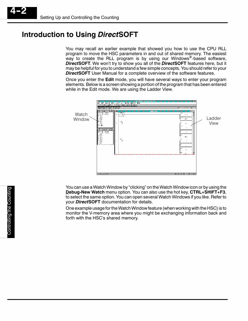
You may recall an earlier example that showed you how to use the CPU RLLprogram to move the HSC parameters in and out of shared memory. The easiestway to create the RLL program is by using our Windows-based software,DirectSOFT. We won’t try to show you all of the DirectSOFT features here, but itmay be helpful for you to understand a few simple concepts. You should refer to yourDirectSOFT User Manual for a complete overview of the software features.Once you enter the Edit mode, you will have several ways to enter your programelements. Below is a screen showing a portion of the program that has been enteredwhile in the Edit mode. We are using the Ladder View.
WatchWindow Ladder
View
You can use a Watch Window by “clicking” on the Watch Window icon or by using theDebug-New Watch menu option. You can also use the hot key, CTRL+SHIFT+F3,to select the same option. You can open several Watch Windows if you like. Refer toyour DirectSOFT documentation for details.One example usage for the Watch Window feature (when working with the HSC) is tomonitor the V-memory area where you might be exchanging information back andforth with the HSC’s shared memory.
Setting
Up
andC
ontrollingthe
Counting4--3
Setting Up and Controlling the Counting
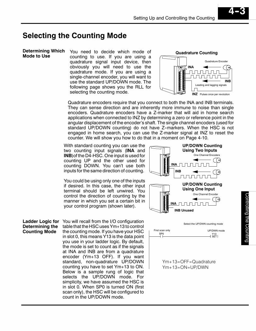
Selecting the Counting Mode
You need to decide which mode ofcounting to use. If you are using aquadrature signal input device, thenobviously you will need to use thequadrature mode. If you are using asingle-channel encoder, you will want touse the standard UP/DOWN mode. Thefollowing page shows you the RLL forselecting the counting mode.
Quadrature Encoder
Quadrature Counting
Leading and lagging signals
INA
INB
INZ Pulses once per revolution
Quadrature encoders require that you connect to both the INA and INB terminals.They can sense direction and are inherently more immune to noise than singleencoders. Quadrature encoders have a Z-marker that will aid in home searchapplications when connected to INZ by determining a zero or reference point in theangular displacement of the encoder’s shaft. The single channel encoders (used forstandard UP/DOWN counting) do not have Z--markers. When the HSC is notengaged in home search, you can use the Z-marker signal at INZ to reset thecounter. We will show you how to do that in a moment on Page 4-10.
With standard counting you can use thetwo counting input signals (INA andINB)of the D4-HSC. One input is used forcounting UP and the other used forcounting DOWN. You can’t use bothinputs for the same direction of counting.
You could be using only one of the inputsif desired. In this case, the other inputterminal should be left unwired. Youcontrol the direction of counting by themanner in which you set a certain bit inyour control program (shown later).
One Channel Encoders
UP/DOWN CountingUsing Two Inputs
INA
INB
One Channel Encoder
INA
INB Unused
UP/DOWN CountingUsing One Input
You will recall from the I/O configurationtable that the HSC uses Ym+13 to controlthe counting mode. If you have your HSCin slot 0, this means Y13 is the data pointyou use in your ladder logic. By default,the mode is set to count as if the signalsat INA and INB are from a quadratureencoder (Ym+13 OFF). If you wantstandard, non-quadrature UP/DOWNcounting you have to set Ym+13 to ON.Below is a sample rung of logic thatselects the UP/DOWN mode. Forsimplicity, we have assumed the HSC isin slot 0. When SP0 is turned ON (firstscan only), the HSC will be configured tocount in the UP/DOWN mode.
Y13SET
SP0UP/DWN modeFirst scan only
Select the UP/DWN counting mode
Ym+13=OFF=QuadratureYm+13=ON=UP/DWN
Determining WhichMode to Use
Ladder Logic forDetermining theCounting Mode
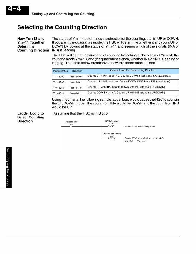
Set
ting
Up
and
Con
trolli
ngth
eC
ount
ing
4--4Setting Up and Controlling the Counting
Selecting the Counting Direction
The status of Ym+14 determines the direction of the counting, that is, UP or DOWN.If you are in the quadrature mode, the HSC will determine whether it is to count UP orDOWN by looking at the status of Ym+14 and seeing which of the signals (INA orINB) is leading.The HSC will determine direction of counting by looking at the status of Ym+14, thecounting mode Ym+13, and (if a quadrature signal), whether INA or INB is leading orlagging. The table below summarizes how this information is used.
Mode Status Direction Criteria Used For Determining Direction
Ym+13=0 Ym+14=0 Counts UP if INA leads INB. Counts DOWN if INB leads INA (quadrature)
Ym+13=0 Ym+14=1 Counts UP if INB lead INA. Counts DOWN if INA leads INB (quadrature)
Ym+13=1 Ym+14=0 Counts UP with INA. Counts DOWN with INB (standard UP/DOWN)
Ym+13=1 Ym+14=1 Counts DOWN with INA. Counts UP with INB (standard UP/DOWN)
Using this criteria, the following sample ladder logic would cause the HSC to count inthe UP/DOWN mode. The count from INA would be DOWN and the count from INBwould be UP.
Assuming that the HSC is in Slot 0:
SP0 Y13SET
First scan only
Select the UP/DWN counting mode
Y14SET
UP/DWN mode
Counts DOWN with INA. Counts UP with INB.
Direction of Counting
Ym+13=1 Ym+14=1
How Ym+13 andYm+14 TogetherDetermineCounting Direction
Ladder Logic toSelect CountingDirection
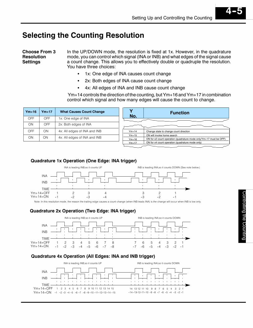
Setting
Up
andC
ontrollingthe
Counting4--5
Setting Up and Controlling the Counting
Selecting the Counting Resolution
In the UP/DOWN mode, the resolution is fixed at 1x. However, in the quadraturemode, you can control which signal (INA or INB) and what edges of the signal causea count change. This allows you to effectively double or quadruple the resolution.You have three choices:
S 1x: One edge of INA causes count changeS 2x: Both edges of INA cause count changeS 4x: All edges of INA and INB cause count change
Ym+14 controls the direction of the counting, but Ym+16 and Ym+17 in combinationcontrol which signal and how many edges will cause the count to change.
FunctionYNo.
Ym+14
Ym+15
Ym+16
Change state to change count direction
ON will invoke home searchON for x2 count operation (quadrature mode only/Ym+17 must be OFF)
Ym+17 ON for x4 count operation (quadrature mode only)
Ym+16 Ym+17
OFFOFF
OFFON
ONOFF
ONON
What Causes Count Change
1x: One edge of INA
2x: Both edges of INA
4x: All edges of INA and INB
4x: All edges of INA and INB
Quadrature 1x Operation (One Edge: INA trigger)
Quadrature 2x Operation (Two Edge: INA trigger)
Quadrature 4x Operation (All Edges: INA and INB trigger)
1 2 3 4 3 2 1--1 --2 --3 --4 --3 --2 --1
INA
INB
TIMEYm+14=OFFYm+14=ON
1 2 3 4 6 4 2--1 --2 --3 --4 --6 --4 --2
INA
INB
TIMEYm+14=OFFYm+14=ON
INA
INB
TIMEYm+14=OFFYm+14=ON
5 6 7 8--5 --6 --7 --8
7 5 3--7 --5 --3
1--1
1 3 5 7
--1 --3 --5 --7
9 11 13 15
--9 --11 --13 --15
2 4 6
--2 --4 --6
8 10 12 14
--8 --10 --12 --1414 13 12 11 10 9 8 7 6 5 4 3 12
--14 --13--12--11--10 --9 --8 --7 --6 --5 --4 --3 --2 --1
INA is leading INB;so it counts UP INB is leading INA;so it counts DOWN (See note below.)
INA is leading INB;so it counts UP INB is leading INA;so it counts DOWN
INA is leading INB;so it counts UP INB is leading INA;so it counts DOWN
Note: In this resolution mode, the reason the trailing edge causes a count change (when INB leads INA) is the change will occur when INB is low only.
Choose From 3ResolutionSettings
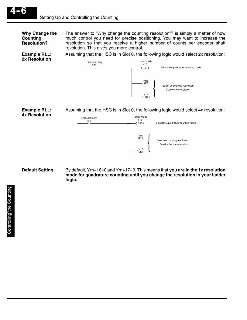
Set
ting
Up
and
Con
trolli
ngth
eC
ount
ing
4--6Setting Up and Controlling the Counting
The answer to “Why change the counting resolution”? is simply a matter of howmuch control you need for precise positioning. You may want to increase theresolution so that you receive a higher number of counts per encoder shaftrevolution. This gives you more control.Assuming that the HSC is in Slot 0, the following logic would select 2x resolution:
SP0 Y13RST
First scan only
Select the quadrature counting mode
Y16SET
quad mode
Y17RST
Select 2x counting resolution
Doubles the resolution
Assuming that the HSC is in Slot 0, the following logic would select 4x resolution:
SP0 Y13RST Select the quadrature counting mode
Y16SET
quad mode
Y17SET
Select 4x counting resolution
Quadruples the resolutiton
First scan only
By default, Ym+16=0 and Ym+17=0. This means that you are in the 1x resolutionmode for quadrature counting until you change the resolution in your ladderlogic.
Why Change theCountingResolution?
Example RLL:2x Resolution
Example RLL:4x Resolution
Default Setting
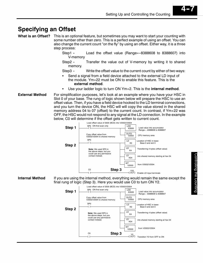
Setting
Up
andC
ontrollingthe
Counting4--7
Setting Up and Controlling the Counting
Specifying an OffsetThis is an optional feature, but sometimes you may want to start your counting withsome number other than zero. This is a perfect example of using an offset. You canalso change the current count “on the fly” by using an offset. Either way, it is a threestep process:
Step1 -- Load the offset value (Range=--8388608 to 8388607) intoV-memory
Step2 -- Transfer the value out of V-memory by writing it to sharedmemory.
Step3 -- Write the offset value to the current count by either of two ways:S Send a signal from a field device attached to the external LD input of
the module. Ym+22 must be ON to enable this feature. This is theexternal method.
S Use your ladder logic to turn ON Ym+2. This is the internal method.
For simplification purposes, let’s look at an example where you have your HSC inSlot 0 of your base. The rung of logic shown below will prepare the HSC to use anoffset value. Then, if you have a field device hooked to the LD terminal connections,and you turn the device ON, the HSC will will copy the value stored in the sharedmemory address 04 to 07 (offset) to the current count. In contrast, if Ym+22 wasOFF, the HSC would not respond to any signal at the LD connection. In the examplebelow, C0 will determine if the offset gets written to current count.
SP0
Copy offset value fromV2003/V2004 to shared memory
K4
WT
LDK04
V2003
SP0
Load offset value of 3500 (BCD) into V2003/V2004
OUTDV2003
LDDK3500
LDK0
LD
Location of HSC in base:Base 0 and slot 0
Transferring 4 bytes (offset value)
into shared memory starting at hex 04
from V2003/V2004
Load value into accumulator
CPU memory area
ON first scan onlyStep 1
Step 2
Y22OUT Enable LD input terminals
Step 3C0
Range= --8388608 to 8388607
Note: We used SP0 inthe above steps, but youcould use any permissivecontact instead.
If you are using the internal method, everything would remain the same except thefinal rung of logic (Step 3). Here you would use C0 to turn ON Y2.
SP0
Copy offset value fromV2003/V2004 to shared memory
K4
WT
LDK04
V2003
SP0
Load offset value of 3500 (BCD) into V2003/V2004
OUTDV2003
LDDK3500
LDK0
LD
Location of HSC in base:Base 0 and slot 0
Transferring 4 bytes (offset value)
into shared memory starting at hex 04
from V2003/V2004
Load value into accumulator
CPU memory area
ON first scan onlyStep 1
Step 2
Y2OUT Transition Y2 from OFF to ON
Step 3
Range= --8388608 to 8388607
C0
Note: We used SP0 inthe above steps, but youcould use any permissivecontact instead.
What is an Offset?
External Method
Internal Method
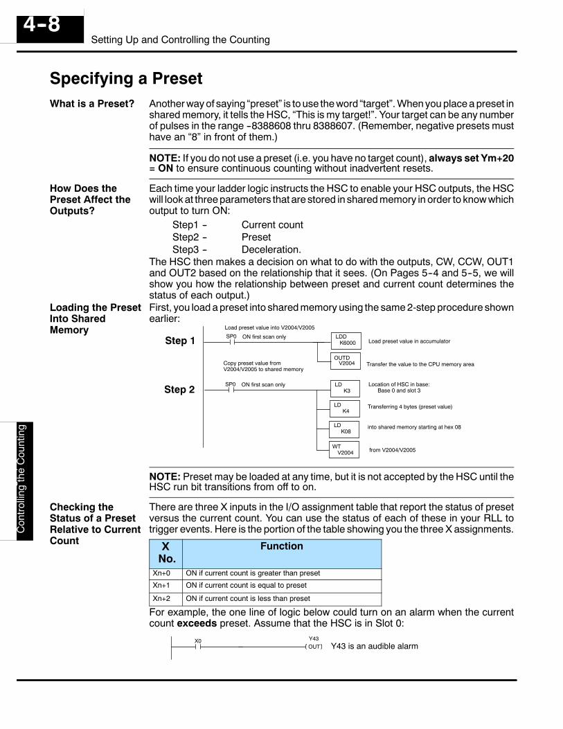
Set
ting
Up
and
Con
trolli
ngth
eC
ount
ing
4--8Setting Up and Controlling the Counting
Specifying a PresetAnother way of saying “preset” is to use the word “target”. When you place a preset inshared memory, it tells the HSC, “This is my target!”. Your target can be any numberof pulses in the range --8388608 thru 8388607. (Remember, negative presets musthave an “8” in front of them.)
NOTE: If you do not use a preset (i.e. you have no target count), always set Ym+20= ON to ensure continuous counting without inadvertent resets.
Each time your ladder logic instructs the HSC to enable your HSC outputs, the HSCwill look at three parameters that are stored in shared memory in order to know whichoutput to turn ON:
Step1 -- Current countStep2 -- PresetStep3 -- Deceleration.
The HSC then makes a decision on what to do with the outputs, CW, CCW, OUT1and OUT2 based on the relationship that it sees. (On Pages 5--4 and 5--5, we willshow you how the relationship between preset and current count determines thestatus of each output.)First, you load a preset into shared memory using the same 2-step procedure shownearlier:
SP0
Copy preset value fromV2004/V2005 to shared memory
K4
WT
LDK08
V2004
SP0
Load preset value into V2004/V2005
OUTDV2004
LDDK6000
LDK3
LD
Location of HSC in base:Base 0 and slot 3
Transferring 4 bytes (preset value)
into shared memory starting at hex 08
from V2004/V2005
Load preset value in accumulator
Transfer the value to the CPU memory area
ON first scan only
ON first scan only
Step 1
Step 2
NOTE: Preset may be loaded at any time, but it is not accepted by the HSC until theHSC run bit transitions from off to on.
There are three X inputs in the I/O assignment table that report the status of presetversus the current count. You can use the status of each of these in your RLL totrigger events. Here is the portion of the table showing you the three X assignments.
XNo.
Function
Xn+0 ON if current count is greater than preset
Xn+1 ON if current count is equal to preset
Xn+2 ON if current count is less than preset
For example, the one line of logic below could turn on an alarm when the currentcount exceeds preset. Assume that the HSC is in Slot 0:
X0 Y43OUT Y43 is an audible alarm
What is a Preset?
How Does thePreset Affect theOutputs?
Loading the PresetInto SharedMemory
Checking theStatus of a PresetRelative to CurrentCount
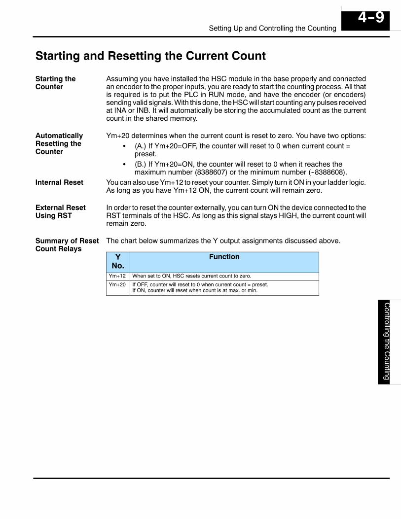
Setting
Up
andC
ontrollingthe
Counting4--9
Setting Up and Controlling the Counting
Starting and Resetting the Current Count
Assuming you have installed the HSC module in the base properly and connectedan encoder to the proper inputs, you are ready to start the counting process. All thatis required is to put the PLC in RUN mode, and have the encoder (or encoders)sending valid signals. With this done, the HSC will start counting any pulses receivedat INA or INB. It will automatically be storing the accumulated count as the currentcount in the shared memory.
Ym+20 determines when the current count is reset to zero. You have two options:S (A.) If Ym+20=OFF, the counter will reset to 0 when current count =
preset.S (B.) If Ym+20=ON, the counter will reset to 0 when it reaches the
maximum number (8388607) or the minimum number (--8388608).You can also use Ym+12 to reset your counter. Simply turn it ON in your ladder logic.As long as you have Ym+12 ON, the current count will remain zero.
In order to reset the counter externally, you can turn ON the device connected to theRST terminals of the HSC. As long as this signal stays HIGH, the current count willremain zero.
The chart below summarizes the Y output assignments discussed above.
YNo.
Function
Ym+12 When set to ON, HSC resets current count to zero.
Ym+20 If OFF, counter will reset to 0 when current count = preset.If ON, counter will reset when count is at max. or min.
Starting theCounter
AutomaticallyResetting theCounter
Internal Reset
External ResetUsing RST
Summary of ResetCount Relays
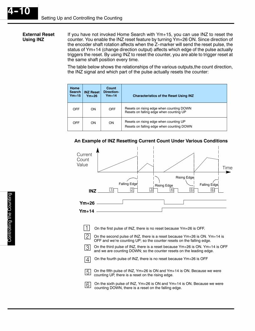
Set
ting
Up
and
Con
trolli
ngth
eC
ount
ing
4--10Setting Up and Controlling the Counting
If you have not invoked Home Search with Ym+15, you can use INZ to reset thecounter. You enable the INZ reset feature by turning Ym+26 ON. Since direction ofthe encoder shaft rotation affects when the Z--marker will send the reset pulse, thestatus of Ym+14 (change direction output) affects which edge of the pulse actuallytriggers the reset. By using INZ to reset the counter, you are able to trigger reset atthe same shaft position every time.
The table below shows the relationships of the various outputs,the count direction,the INZ signal and which part of the pulse actually resets the counter:
HomeSearchYm+15
INZ ResetYm+26
CountDirection-
Ym+14 Characteristics of the Reset Using INZ
OFF
OFF
ON
ON ON
OFF
Resets on rising edge when counting UPResets on falling edge when counting DOWN
Resets on rising edge when counting DOWNResets on falling edge when counting UP
CurrentCountValue
Time
INZ
Falling Edge Rising Edge
Ym+26
Ym+14
¡©¢
£
¤ ¥
¤
¥
¡ © ¢ £
On the first pulse of INZ, there is no reset because Ym+26 is OFF.
On the second pulse of INZ, there is a reset because Ym+26 is ON. Ym+14 isOFF and we’re counting UP; so the counter resets on the falling edge.
On the third pulse of INZ, there is a reset because Ym+26 is ON. Ym+14 is OFFand we are counting DOWN; so the counter resets on the leading edge.
On the fourth pulse of INZ, there is no reset because Ym+26 is OFF
On the fifth pulse of INZ, Ym+26 is ON and Ym+14 is ON. Because we werecounting UP, there is a reset on the rising edge.
On the sixth pulse of INZ, Ym+26 is ON and Ym+14 is ON. Because we werecounting DOWN, there is a reset on the falling edge.
An Example of INZ Resetting Current Count Under Various Conditions
Falling Edge
Rising Edge
External ResetUsing INZ
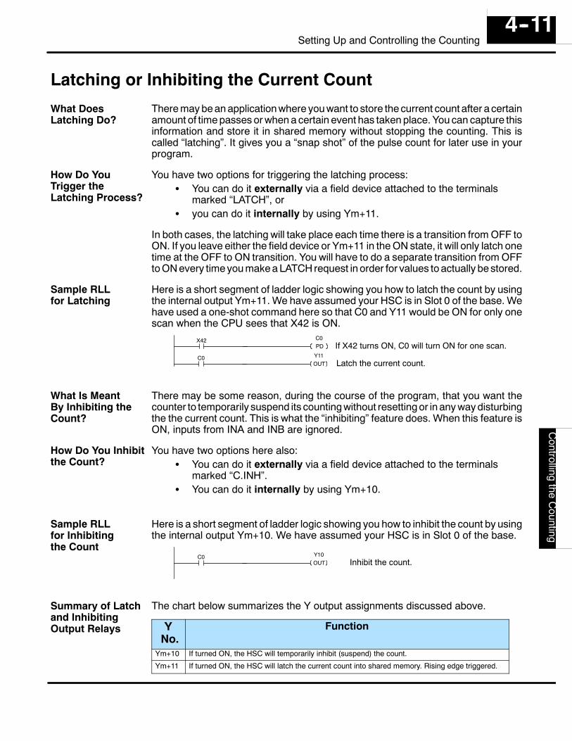
Setting
Up
andC
ontrollingthe
Counting4--11
Setting Up and Controlling the Counting
Latching or Inhibiting the Current Count
There may be an application where you want to store the current count after a certainamount of time passes or when a certain event has taken place. You can capture thisinformation and store it in shared memory without stopping the counting. This iscalled “latching”. It gives you a “snap shot” of the pulse count for later use in yourprogram.
You have two options for triggering the latching process:S You can do it externally via a field device attached to the terminals
marked “LATCH”, orS you can do it internally by using Ym+11.
In both cases, the latching will take place each time there is a transition from OFF toON. If you leave either the field device or Ym+11 in the ON state, it will only latch onetime at the OFF to ON transition. You will have to do a separate transition from OFFto ON every time you make a LATCH request in order for values to actually be stored.
Here is a short segment of ladder logic showing you how to latch the count by usingthe internal output Ym+11. We have assumed your HSC is in Slot 0 of the base. Wehave used a one-shot command here so that C0 and Y11 would be ON for only onescan when the CPU sees that X42 is ON.
C0 Y11OUT Latch the current count.
X42 C0PD If X42 turns ON, C0 will turn ON for one scan.
There may be some reason, during the course of the program, that you want thecounter to temporarily suspend its counting without resetting or in any way disturbingthe the current count. This is what the “inhibiting” feature does. When this feature isON, inputs from INA and INB are ignored.
You have two options here also:S You can do it externally via a field device attached to the terminals
marked “C.INH”.S You can do it internally by using Ym+10.
Here is a short segment of ladder logic showing you how to inhibit the count by usingthe internal output Ym+10. We have assumed your HSC is in Slot 0 of the base.
C0 Y10OUT Inhibit the count.
The chart below summarizes the Y output assignments discussed above.
YNo.
Function
Ym+10 If turned ON, the HSC will temporarily inhibit (suspend) the count.
Ym+11 If turned ON, the HSC will latch the current count into shared memory. Rising edge triggered.
What DoesLatching Do?
How Do YouTrigger theLatching Process?
Sample RLLfor Latching
What Is MeantBy Inhibiting theCount?
How Do You Inhibitthe Count?
Sample RLLfor Inhibitingthe Count
Summary of Latchand InhibitingOutput Relays
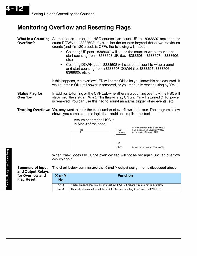
Set
ting
Up
and
Con
trolli
ngth
eC
ount
ing
4--12Setting Up and Controlling the Counting
Monitoring Overflow and Resetting Flags
As mentioned earlier, the HSC counter can count UP to +8388607 maximum orcount DOWN to --8388608. If you pulse the counter beyond these two maximumcounts (and Ym+20 ,reset, is OFF), the following will happen:
S Counting UP past +8388607 will cause the count to wrap around andstart counting from --8388608 UP. (i.e. --8388608, --8388607, --8388606,etc.)
S Counting DOWN past --8388608 will cause the count to wrap aroundand start counting from +8388607 DOWN (i.e. 8388607, 8388606,8388605, etc.).
If this happens, the overflow LED will come ON to let you know this has occurred. Itwould remain ON until power is removed, or you manually reset it using by Ym+1.
In addition to turning on the OVF LED when there is a counting overflow, the HSC willalso mirror the status in Xn+3. This flag will stay ON until Ym+1 is turned ON or poweris removed. You can use this flag to sound an alarm, trigger other events, etc.
You may want to track the total number of overflows that occur. The program belowshows you some example logic that could accomplish this task.
X3
Assuming that the HSC isin Slot 0 of the base
INCV3000
X3 turns on when there is an overflow.It will increment whatever is in V3000by 1 everytime X3 goes HIGH.
OUT
Y1
Turn ON Y1 to reset X3 (Turn it OFF).
When Ym+1 goes HIGH, the overflow flag will not be set again until an overflowoccurs again.
The chart below summarizes the X and Y output assignments discussed above.
X or YNo.
Function
Xn+3 If ON, it means that you are in overflow. If OFF, it means you are not in overflow.
Ym+1 This output relay will reset (turn OFF) the overflow flag Xn+3 and the OVF LED.
What is a CountingOverflow?
Status Flag forOverflow
Tracking Overflows
Summary of Inputand Output Relaysfor Overflow andFlag Reset
15Controlling theOutputs
In This Chapter. . . .— Introduction— Manual Output Control— Automatic Output Control— Using the Direction Outputs— Timing Diagrams for HSC RUN— Using the Speed Outputs with the Direction Outputs
D4-
-HS
CC
ontro
lling
the
Out
puts
5--2Controlling the Outputs
Introduction
The HSC has four output signals:S CW—a signal usually connected to the motor controller’s input that has
been programmed for clockwise motion.S CCW—a signal usually connected to the motor controller’s input that
has been programmed for counter-clockwise motion.S OUT1—a signal usually connected to the motor controller’s input that
has been programmed for deceleration.S OUT2—a signal usually connected to the motor controller’s input that
has been programmed to brake.
If you were to look at each of the above four signals with a VOM or an oscilloscope,they would all look the same. They are simply constant DC output signals whosevoltage is directly dependent on the rating of the external power supply. What isimportant is the point in time in your RLL program that you turn them ON or OFF andhow your motor controller (to which they are connected) is either hard-wired orprogrammed.
The HSC has four output relays for turning ON each of the HSC control outputs:S Ym+6—turns ON CW.S Ym+4—turns ON CCW.S Ym+7—turns ON deceleration signal.S Ym+5—turns ON brake signal.
You do not have to use the output relays shown above, but they are there if you needthem. In the pages that follow, we will show you how to either invoke a program thatwill turn ON and OFF each of the control outputs in an ordered sequenceautomatically, or how to do it manually by using the 4 internal relays just described.Both ways require ladder logic, but they are very different in terms of flexibility. Wewill be explaining each method in great detail.
The 4 ControlOutputs
All the OutputSignals Look theSame
The 4 Y OutputRelays for TurningON Each ControlOutput
Using the Y OutputRelays to Controlthe Outputs isOptional
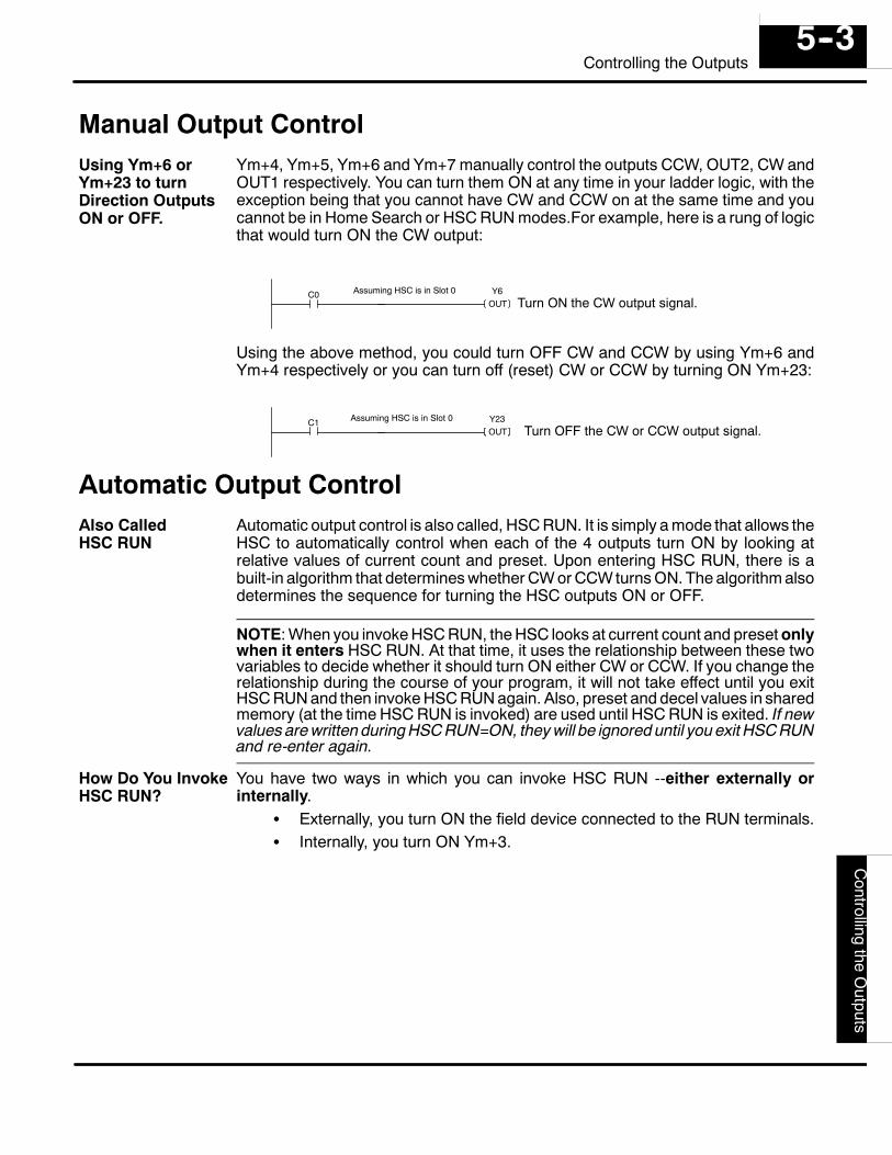
D4--H
SC
Controlling
theO
utputs5--3
Controlling the Outputs
Manual Output ControlYm+4, Ym+5, Ym+6 and Ym+7 manually control the outputs CCW, OUT2, CW andOUT1 respectively. You can turn them ON at any time in your ladder logic, with theexception being that you cannot have CW and CCW on at the same time and youcannot be in Home Search or HSC RUN modes.For example, here is a rung of logicthat would turn ON the CW output:
C0 Y6OUT Turn ON the CW output signal.
Assuming HSC is in Slot 0
Using the above method, you could turn OFF CW and CCW by using Ym+6 andYm+4 respectively or you can turn off (reset) CW or CCW by turning ON Ym+23:
C1 Y23OUT Turn OFF the CW or CCW output signal.
Assuming HSC is in Slot 0
Automatic Output ControlAutomatic output control is also called, HSC RUN. It is simply a mode that allows theHSC to automatically control when each of the 4 outputs turn ON by looking atrelative values of current count and preset. Upon entering HSC RUN, there is abuilt-in algorithm that determines whether CW or CCW turns ON. The algorithm alsodetermines the sequence for turning the HSC outputs ON or OFF.
NOTE: When you invoke HSC RUN, the HSC looks at current count and preset onlywhen it enters HSC RUN. At that time, it uses the relationship between these twovariables to decide whether it should turn ON either CW or CCW. If you change therelationship during the course of your program, it will not take effect until you exitHSC RUN and then invoke HSC RUN again. Also, preset and decel values in sharedmemory (at the time HSC RUN is invoked) are used until HSC RUN is exited. If newvalues are written during HSC RUN=ON, they will be ignored until you exit HSC RUNand re-enter again.
You have two ways in which you can invoke HSC RUN --either externally orinternally.
S Externally, you turn ON the field device connected to the RUN terminals.S Internally, you turn ON Ym+3.
Using Ym+6 orYm+23 to turnDirection OutputsON or OFF.
Also CalledHSC RUN
How Do You InvokeHSC RUN?
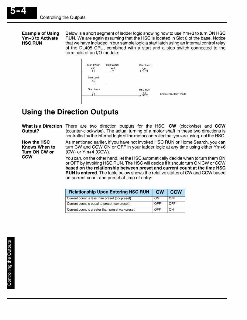
D4-
-HS
CC
ontro
lling
the
Out
puts
5--4Controlling the Outputs
Below is a short segment of ladder logic showing how to use Ym+3 to turn ON HSCRUN. We are again assuming that the HSC is located in Slot 0 of the base. Noticethat we have included in our sample logic a start latch using an internal control relayof the DL405 CPU, combined with a start and a stop switch connected to theterminals of an I/O module:
C0OUT
X40 X42
C0
Y3SET
C0
Start Switch Stop Switch
Start Latch
Start Latch
Enable HSC RUN mode
HSC RUNStart Latch
Using the Direction Outputs
There are two direction outputs for the HSC: CW (clockwise) and CCW(counter-clockwise). The actual turning of a motor shaft in these two directions iscontrolled by the internal logic of the motor controller that you are using, not the HSC.As mentioned earlier, if you have not invoked HSC RUN or Home Search, you canturn CW and CCW ON or OFF in your ladder logic at any time using either Ym+6(CW) or Ym+4 (CCW).You can, on the other hand, let the HSC automatically decide when to turn them ONor OFF by invoking HSC RUN. The HSC will decide if it should turn ON CW or CCWbased on the relationship between preset and current count at the time HSCRUN is entered. The table below shows the relative states of CW and CCW basedon current count and preset at time of entry:
Relationship Upon Entering HSC RUN CW CCWCurrent count is less than preset (cc<preset) ON OFF
Current count is equal to preset (cc=preset) OFF OFF
Current count is greater than preset (cc>preset) OFF ON
Example of UsingYm+3 to ActivateHSC RUN
What is a DirectionOutput?
How the HSCKnows When toTurn ON CW orCCW
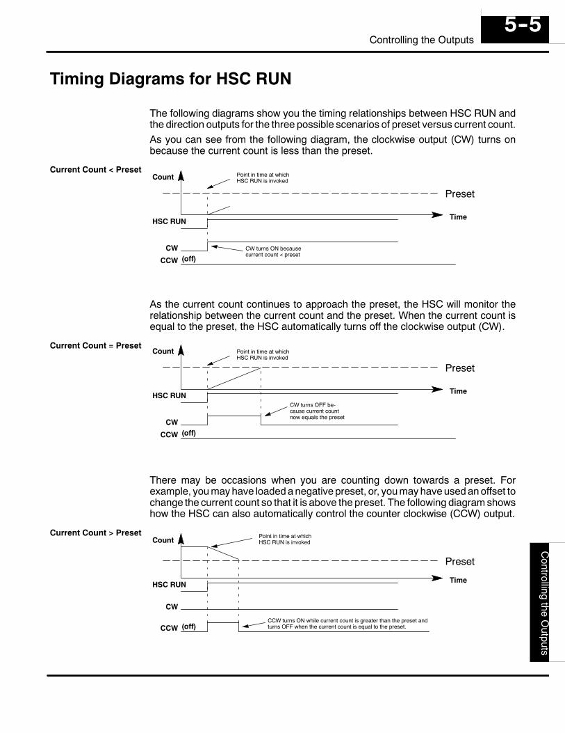
D4--H
SC
Controlling
theO
utputs5--5
Controlling the Outputs
Timing Diagrams for HSC RUN
The following diagrams show you the timing relationships between HSC RUN andthe direction outputs for the three possible scenarios of preset versus current count.As you can see from the following diagram, the clockwise output (CW) turns onbecause the current count is less than the preset.
Preset
CCW
CW(off)
HSC RUN
Count
Time
Point in time at whichHSC RUN is invoked
CW turns ON becausecurrent count < preset
As the current count continues to approach the preset, the HSC will monitor therelationship between the current count and the preset. When the current count isequal to the preset, the HSC automatically turns off the clockwise output (CW).
Preset
CCW
CW(off)
HSC RUN
Count
Time
CW turns OFF be-cause current countnow equals the preset
Point in time at whichHSC RUN is invoked
There may be occasions when you are counting down towards a preset. Forexample, you may have loaded a negative preset, or, you may have used an offset tochange the current count so that it is above the preset. The following diagram showshow the HSC can also automatically control the counter clockwise (CCW) output.
Preset
CCW
CW
(off)
HSC RUN
Count
Time
CCW turns ON while current count is greater than the preset andturns OFF when the current count is equal to the preset.
Point in time at whichHSC RUN is invoked
Current Count < Preset
Current Count = Preset
Current Count > Preset
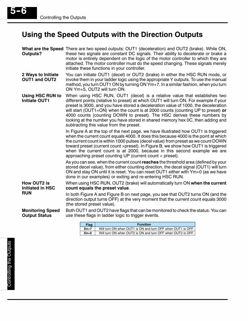
D4-
-HS
CC
ontro
lling
the
Out
puts
5--6Controlling the Outputs
Using the Speed Outputs with the Direction Outputs
There are two speed outputs: OUT1 (deceleration) and OUT2 (brake). While ON,these two signals are constant DC signals. Their ability to decelerate or brake amotor is entirely dependent on the logic of the motor controller to which they areattached. The motor controller must do the speed changing. These signals merelyinitiate these functions in your controller.You can initiate OUT1 (decel) or OUT2 (brake) in either the HSC RUN mode, orinvoke them in your ladder logic using the appropriate Y outputs. To use the manualmethod, you turn OUT1 ON by turning ON Ym+7. In a similar fashion, when you turnON Ym+5, OUT2 will turn ON.When using HSC RUN, OUT1 (decel) is a relative value that establishes twodifferent points (relative to preset) at which OUT1 will turn ON. For example if yourpreset is 3000, and you have stored a deceleration value of 1000, the decelerationwill start (OUT1=ON) when the count is at 2000 counts (counting UP to preset) or4000 counts (counting DOWN to preset). The HSC derives these numbers bylooking at the number you have stored in shared memory hex 0C, then adding andsubtracting this value from the preset.In Figure A at the top of the next page, we have illustrated how OUT1 is triggeredwhen the current count equals 4000. It does this because 4000 is the point at whichthe current count is within 1000 pulses (decel value) from preset as we count DOWNtoward preset (current count >preset). In Figure B, we show how OUT1 is triggeredwhen the current count is at 2000, because in this second example we areapproaching preset counting UP (current count < preset).As you can see, when the current count reaches the threshold area (defined by yourstored decel value), from either counting direction, the decel signal (OUT1) will turnON and stay ON until it is reset. You can reset OUT1 either with Ym+0 (as we havedone in our examples) or exiting and re-entering HSC RUN.When using HSC RUN, OUT2 (brake) will automatically turn ON when the currentcount equals the preset value.In both Figure A and Figure B on next page, you see that OUT2 turns ON (and thedirection output turns OFF) at the very moment that the current count equals 3000(the stored preset value).Both OUT1 and OUT2 have flags that can be monitored to check the status. You canuse these flags in ladder logic to trigger events.
Flag FunctionXn+7Xn+5
Will turn ON when OUT1 is ON and turn OFF when OUT1 is OFF.Will turn ON when OUT2 is ON and turn OFF when OUT2 is OFF.
What are the SpeedOutputs?
2 Ways to InitiateOUT1 and OUT2
Using HSC RUN toInitiate OUT1
How OUT2 isInitiated in HSCRUN
Monitoring SpeedOutput Status
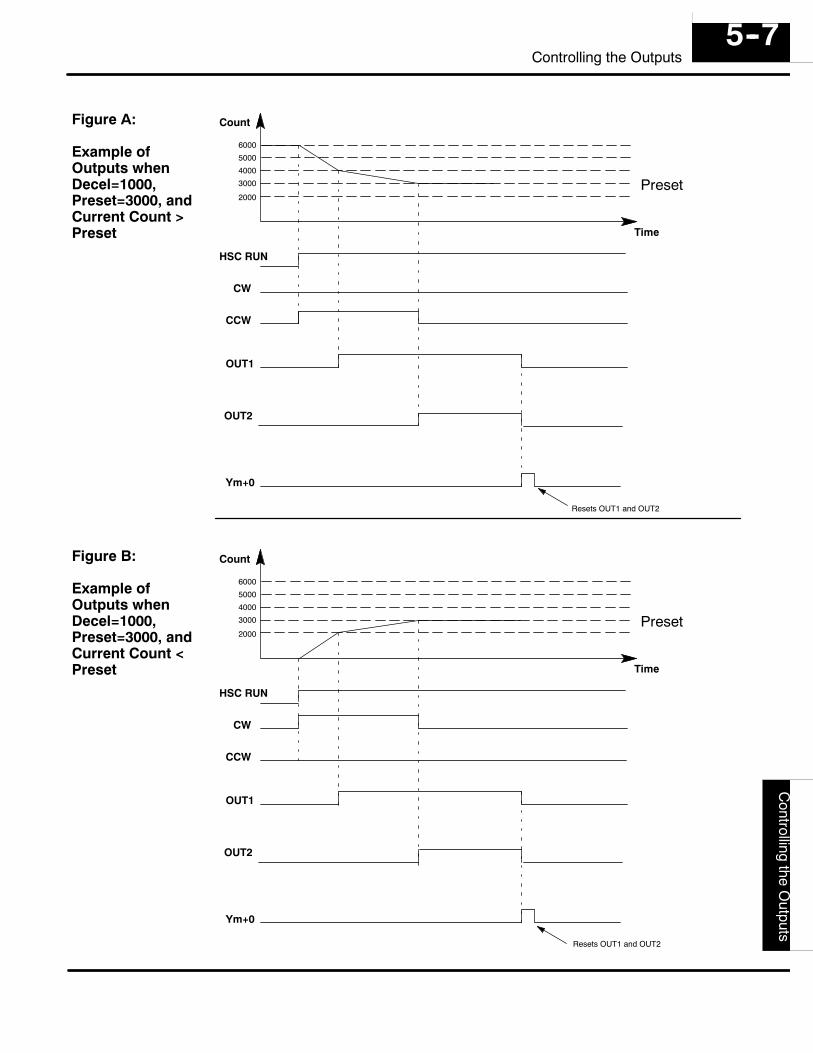
D4--H
SC
Controlling
theO
utputs5--7
Controlling the Outputs
Preset
CW
HSC RUN
Count
Time
OUT1
4000
3000
2000
Ym+0
Resets OUT1 and OUT2
CCW
6000
5000
OUT2
Preset
CW
HSC RUN
Count
Time
OUT1
4000
3000
2000
Ym+0
Resets OUT1 and OUT2
CCW
6000
5000
OUT2
Figure A:
Example ofOutputs whenDecel=1000,Preset=3000, andCurrent Count >Preset
Figure B:
Example ofOutputs whenDecel=1000,Preset=3000, andCurrent Count <Preset
16Special Features
In This Chapter. . . .— Planning a Home Search Application— Using Sampling
D4-
-HS
CS
peci
alFe
atur
es6--2
Special Features
Planning a Home Search ApplicationWe discussed briefly in Chapter 1 some of the basics concerning the automatic home searchfeature of the HSC. Here we will elaborate further.
The built-in algorithm of the HSC assumes that you have specified certain types of fielddevices for your home search system. It also assumes they have been physically configuredin a certain manner. Let’s take a closer look:
S LS2 must be a negative logic switch (i.e. turn OFF when work is near).S The status of LS1 must always be ON during Home Search. An actual physical
device is not required as long as the input point (LS1) is always HIGH duringHome Search. If you attach a switch to LS1, make sure it is the negative logictype also.
S LD must be a positive logic switch (i.e. turn ON when work is near).S In relationship to the motor and its shaft rotation, the LS1 switch must be
located so that when the motor turns clockwise, the moving work apparatustravels in the direction of the LS1 switch. Likewise, when the motor movescounter-clockwise, the work apparatus moves toward the LS2 switch.
S LS1 and LS2 define the two ends of the work area. The Home Search algorithmuses the status of these two input points while locating home position.
S Home position is defined to be near LD on the LS2 side.
In the diagram on the opposite page, assume that the drill head has just performed its lasttask on the work piece and has been raised. Your ladder logic has invoked home search (OFFto ON transition of Ym+15). The status of all your outputs are stored in memory, becausewhen Home Search is complete the outputs will be returned to their original state. We willassume that the pitch of the lead screw is such that CCW movement is to the left toward LS2:
Step1 -- CCW turns ON and moves the drill head toward LS2 at full speed.
Step2 -- When LS2 detects the drill head and turns OFF, CW is turned ON (CCWOFF), and movement is back toward LD at full speed.
Step3 -- When LD turns ON, OUT1 (deceleration) turns ON.
Step4 -- The drill head moves slowly past LD until LD turns OFF.
Step5 -- When LD has turned OFF, CCW is once again turned ON, and with OUT1 stillON, it moves slowly toward LD again. LD turns ON. Drill head continues movinguntil LD turns OFF.
Step6 -- If you were in the UP/DOWN mode of counting, the drill head would stop assoon as LD turns OFF. Home is defined as that position. This would be the end ofHome Search for the UP/DOWN mode. Read the note below for use of Ym+27(enabling OUT2, the brake) to assure that momentum does not cause overshoot.
Step7 -- If you were in the Quadrature mode of counting, the drill head wouldnot stop when LD turns OFF. It would, continue until INZ turns ON. It wouldstop at this point and the Home Search would be finished. Read the notebelow for use of Ym+27 (enabling OUT2, the brake) to assure thatmomentum does not cause overshoot.
NOTE: If you want the brake (OUT2) to turn ON when Home is found, then you mustturn ON Ym+27 before invoking Home Search. This feature is only supported in HSCmodules with date codes 9502 (Feb. ’95)or later. You will find this production date onthe bar coded label located on the side of the module.
Requirements forHome Search
Example of HomeSearch Application
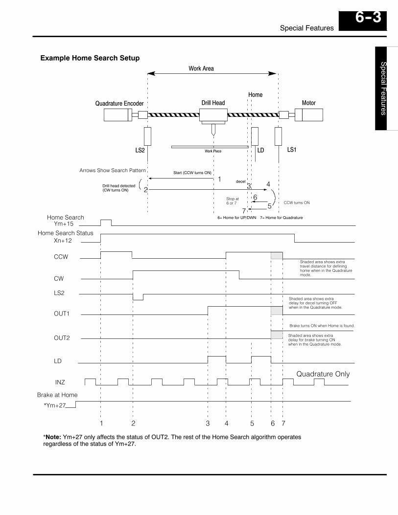
D4--H
SC
SpecialFeatures
6--3Special Features
1 2 3 4 5 6 7
Ym+15
LD
LS2
CW
INZ
OUT1
Xn+12
Quadrature Only
CCWShaded area shows extratravel distance for defininghome when in the Quadraturemode.
Home Search
Home Search Status
Shaded area shows extradelay for decel turning OFFwhen in the Quadrature mode.
3
LD LS1LS2
Drill Head MotorQuadrature EncoderHome
Work Piece
Work Area
Arrows Show Search Pattern
26
Example Home Search Setup
14
57
6= Home for UP/DWN 7= Home for Quadrature
Start (CCW turns ON)
Drill head detected(CW turns ON)
decel
CCW turns ONStop at6 or 7
OUT2 Shaded area shows extradelay for brake turning ONwhen in the Quadrature mode.
*Ym+27
Brake at Home
Brake turns ON when Home is found.
*Note: Ym+27 only affects the status of OUT2. The rest of the Home Search algorithm operatesregardless of the status of Ym+27.
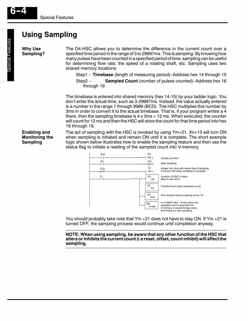
D4-
-HS
CS
peci
alFe
atur
es6--4
Special Features
Using Sampling
The D4-HSC allows you to determine the difference in the current count over aspecified time period in the range of 3 to 29997ms. This is sampling. By knowing howmany pulses have been counted in a specified period of time, sampling can be usefulfor determining flow rate, the speed of a rotating shaft, etc. Sampling uses twoshared memory locations:
Step1 -- Timebase (length of measuring period)--Address hex 14 through 15Step2 -- Sampled Count (number of pulses counted)--Address hex 16
through 19
The timebase is entered into shared memory (hex 14-15) by your ladder logic. Youdon’t enter the actual time, such as 3-29997ms. Instead, the value actually enteredis a number in the range 1 through 9999 (BCD). The HSC multiplies this number by3ms in order to convert it to the actual timebase. That is, if your program writes a 4there, then the sampling timebase is 4 x 3ms = 12 ms. When executed, the counterwill count for 12 ms and then the HSC will store the count for that time period into hex16 through 19.The act of sampling with the HSC is invoked by using Ym+21. Xn+13 will turn ONwhen sampling is initiated and remain ON until it is complete. The short examplelogic shown below illustrates how to enable the sampling feature and then use thestatus flag to initiate a reading of the sampled count into V-memory.
C1
K4
RD
LDK16
V1400
LDK0
LD
Location of HSC in base:Base 0 and slot 0
Transferring 4 bytes (sampled count)
from shared memory starting at hex 16
to V1400/V1401 . At this point, thesampled count is scanned intoV-memory. It would change everytime there is a new sampling.
Initiate one--shot with status flag of samplingIt will turn ON when sampling is complete.
Start sampling
Initiate one-shot
C0PD
Y21OUT
C1PD
X42
C0
X13
You should probably take note that Ym +21 does not have to stay ON. If Ym +21 isturned OFF, the sampling process would continue until completion anyway.
NOTE: When using sampling, be aware that any other function of the HSC thatalters or inhibits the current count (i.e reset, offset, count inhibit) will affect thesampling.
Why UseSampling?
Enabling andMonitoring theSampling
D4--H
SC
SpecialFeatures
6--5Special Features
As mentioned, if you want to compute the value of the number to store in sharedmemory for your timebase, then you will have to divide your actual timebase value by3ms. For example, suppose you wanted a time base of 300ms. You would store300ms/3ms in shared memory hex 14 thru 15:
300ms 3ms = 100Not every timebase computation is going to come out with integer values. Forexample, if you want a time base of 1000ms, here is the math:
1000ms 3ms = 333.33A normal question at this juncture is “How do I enter a value with ladder logic that hasa decimal point?”. The answer is: You can’t. You will have to enter the nearestinteger, which is 333. This means your actual time base is 999ms.In most cases, this will not cause you any problems. You could, for example, in mostcases accomplish whatever you want with the sampling even though it is missing1ms of sampling time. However, with very high speed counting and a need to use thisfeature to determine frequency, you could experience difficulty. You should be awareof this when planning your application.The chart below summarizes the X and Y output assignments for sampling.
X or YNo.
Function
Xn+13 Reports the status of sampling process. ON during the process.OFF when sampling is finished or not taking place.
Ym+21 Transition from OFF to ON enables the sampling process.Turning this relay OFF will not stop the sampling process. It continues to completion.
How to Calculatethe Timebase
What Happens IfYou Want to Entera Value withDecimal Points?
Summary of Inputand Output Relaysfor Sampling
17ProgramApplications
In This Chapter. . . .— A Quick Checkout of the Module— Application No. 1: Drilling Operation— Application No. 2: Cut-to-Length Operation
D4-
-HS
CP
rogr
amA
pplic
atio
ns7--2
Program Applications
A Quick Checkout of the ModuleThe configuration shown below and the RLL on the adjacent page are not intended foractual application of the D4-HSC, but rather is shown as a means to quickly checkout themain functions of the module — namely its counting and output capability. In thisconfiguration, we are using an internal special purpose relay (SP7) of the DL-405 togenerate a low frequency pulse signal for the inputs of the D4-HSC. DirectSOFTprogramming and its Watch Window capability can be used to monitor the counting andpreset versus current count relationship. The color coding of DirectSOFT’s ladder logiccan show you the status of your various outputs. You can also visually watch the LED’s ofthe module to witness all of these functions.It is assumed the HSC is in slot 0 and you have a sourcing DC output module in Slot 1.There is also an input module with a switch attached or an input simulator in Slot 2. Hereis how the program works:
1. On power up, SP0 comes ON, loading your preset and deceleration values intothe shared memory of the HSC.
2. When you turn on X20 (start switch) via the input module or simulator, Y12 setsthe counter to zero.
3. When the counter is set to zero, X2 turns ON and this causes Y3 (HSC RUNmode) to be activated.
4. At this point, CW turns on because current count is less than preset. The HSCis constantly comparing the value of your current count with your preset.
5. When the count value equals your deceleration value, OUT1 will turn ON.6. When current count and preset are equal, CW turns OFF and OUT2 (brake)
turns ON.7. At this point, X1 turns ON and Y40 stops pulsing. Y3 is also reset causing an
exit of HSC RUN. You will notice that OUT1and OUT2stay ON even thoughweexit the HSC RUN mode. If you wish these to turn OFF before exiting, you willhave to turn ON Y0 first, and then exit. The outputs will also reset when HSCRUN is invoked again.
This is a list of items that you will need in order to set up the Quick Checkout for themodule:
S DL405 series CPU/Power Supply unit (DL430 or DL440)S Mounting base for the above (with at least 3 empty slots)S Any current sourcing DC output moduleS D4-HSC module (mounted in Slot 0 of the base)S Either an input simulator or an input module with switch attached
What It Does
How It Works
Things YouNeed for theExample
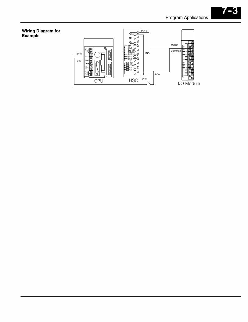
7--3Program Applications
LDRSTLATCHC.INHRUNLS1LS2
CWCCWOUT1OUT2
HSCI/O Module
0utput
Common
INA +
INA--
24V--
24V+CPU
24V+
24V--
Wiring Diagram forExample
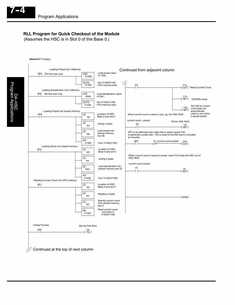
D4--H
SC
Program
Applications
7--4Program Applications
DirectSOFT Display
SP0
V1402
SP0
OUTDV1400
LDDK1000
LDDK500
SP0
K4
WT
LDK8
V1400
LDK0
END
Continued at the top of next column
Continued from adjacent column
OUTD
LD
Load deceleration valueof 500...
into V1400/V1401CPU memory area
Location of HSC:Base 0 and slot 0
writing 4 bytes
Load preset intoshared memoryhex 08
from V1400/V1401
ON first scan only
ON first scan only
SP0
K4
WT
LDK0C
V1402
LDK0
LD
Location of HSC:Base 0 and slot 0
writing 4 bytes
Load deceleration intoshared memory hex 0C
from V1402/V1403
SP1
K4
RD
LDK0
V1404
LDK0
LD
Location of HSC:Base 0 and slot 0
Reading 4 bytes
Specify current countfrom shared memoryhex 0
Read current countand store in
V1404/V1405
Y12OUT
C0
Y13SET
Reset Current Count
UP/DWN mode
Y20SET
Set Y20 so currentcount does notautomaticallyreset to zero whenit equals preset
C0PD
X20
Y3SET
X2
When current count is reset to zero, go into HSC RUN
Y40OUT
SP7 X1
Y3RST
X1
Load preset valueof 1000...
into V1402/V1403CPU memory area
Loading Preset into V-Memory
Loading Deceleration into V-Memory
Loading Preset into shared memory
Loading Decel into shared memory
Reading Current Count into CPU memory
Initiate Process Set Up One-Shot
SP7 is an alternate scan relay that is used to pulse Y40to generate a pulse train. Y40 is wired to the INA input to simulatean encoder
When current count is equal to preset, reset Y3 to take the HSC out ofHSC RUN.
RLL Program for Quick Checkout of the Module(Assumes the HSC is in Slot 0 of the Base 0.)
current count=preset
current count < preset ON for HSC RUN
current count=preset
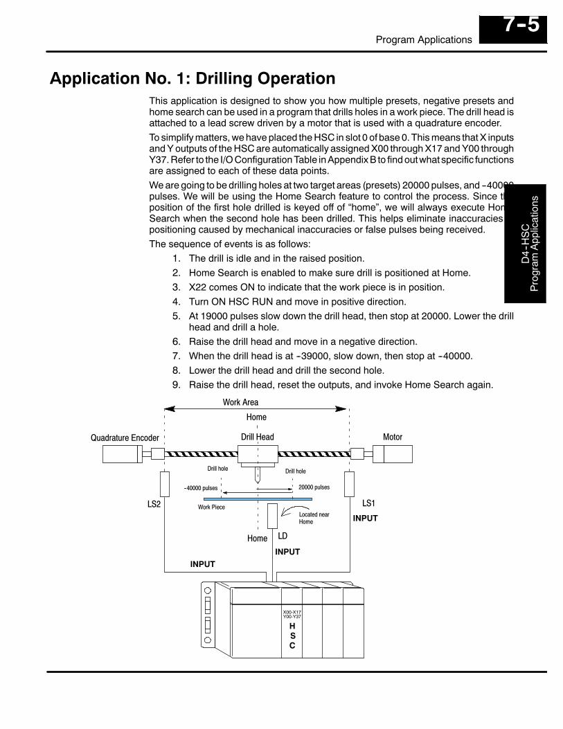
D4-
-HS
CP
rogr
amA
pplic
atio
ns
7--5Program Applications
Application No. 1: Drilling OperationThis application is designed to show you how multiple presets, negative presets andhome search can be used in a program that drills holes in a work piece. The drill head isattached to a lead screw driven by a motor that is used with a quadrature encoder.To simplify matters, we have placed the HSC in slot 0 of base 0. This means that X inputsand Y outputs of the HSC are automatically assigned X00 through X17 and Y00 throughY37. Refer to the I/O Configuration Table in Appendix B to find outwhat specific functionsare assigned to each of these data points.We are going to be drilling holes at two target areas (presets) 20000 pulses, and --40000pulses. We will be using the Home Search feature to control the process. Since theposition of the first hole drilled is keyed off of “home”, we will always execute HomeSearch when the second hole has been drilled. This helps eliminate inaccuracies inpositioning caused by mechanical inaccuracies or false pulses being received.The sequence of events is as follows:
1. The drill is idle and in the raised position.2. Home Search is enabled to make sure drill is positioned at Home.3. X22 comes ON to indicate that the work piece is in position.4. Turn ON HSC RUN and move in positive direction.5. At 19000 pulses slow down the drill head, then stop at 20000. Lower the drill
head and drill a hole.6. Raise the drill head and move in a negative direction.7. When the drill head is at --39000, slow down, then stop at --40000.8. Lower the drill head and drill the second hole.9. Raise the drill head, reset the outputs, and invoke Home Search again.
LD
LS1LS2
Drill Head MotorQuadrature Encoder
Home
Work Piece
Work Area
HSC
INPUTINPUT
INPUT
Home
Located nearHome
X00-X17Y00-Y37
20000 pulses--40000 pulses
Drill holeDrill hole
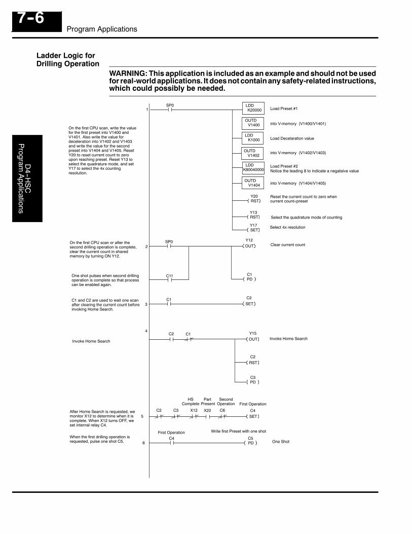
D4--H
SC
Program
Applications
7--6Program Applications
WARNING: This application is included as an example and should not be usedfor real-world applications. It does not containany safety-related instructions,which could possibly be needed.
SP0
V1400
OUTD
LDDK1000
V1402
LDDK20000
OUTD
Load Preset #1
One Shot
C4SET
C5PD
C2
C4
OUTD
LDDK80040000
V1404
Y13RST
Load Preset #2
Load Decelaration value
into V-memory (V1400/V1401)
into V-memory (V1402/V1403)
into V-memory (V1404/V1405)
Reset the current count to zero whencurrent count=preset
1
2SP0 Y12
OUT
C1PD
C3 X22 C6
First Operation
Clear current count
3
4
5
When the first drilling operation isrequested, pulse one shot C5.
On the first CPU scan, write the valuefor the first preset into V1400 andV1401. Also write the value fordeceleration into V1402 and V1403and write the value for the secondpreset into V1404 and V1405. ResetY20 to reset current count to zeroupon reaching preset. Reset Y13 toselect the quadrature mode, and setY17 to select the 4x countingresolution. Notice the leading 8 to indicate a negataive value
Y17SET
Select 4x resolution
Y20RST
Select the quadrature mode of counting
C1 C2SET
On the first CPU scan or after thesecond drilling operation is complete,clear the current count in sharedmemory by turning ON Y12.
C11One shot pulses when second drillingoperation is complete so that processcan be enabled again.
C1 and C2 are used to wait one scanafter clearing the current count beforeinvoking Home Search.
Y15OUT
C2 C1
C2RST
C3PD
Invoke Home Search
X12
Invoke Home Search
After Home Search is requested, wemonitor X12 to determine when it iscomplete. When X12 turns OFF, weset internal relay C4.
First OperationSecond
OperationPart
PresentHS
Complete
Write first Preset with one shot
6
Ladder Logic forDrilling Operation
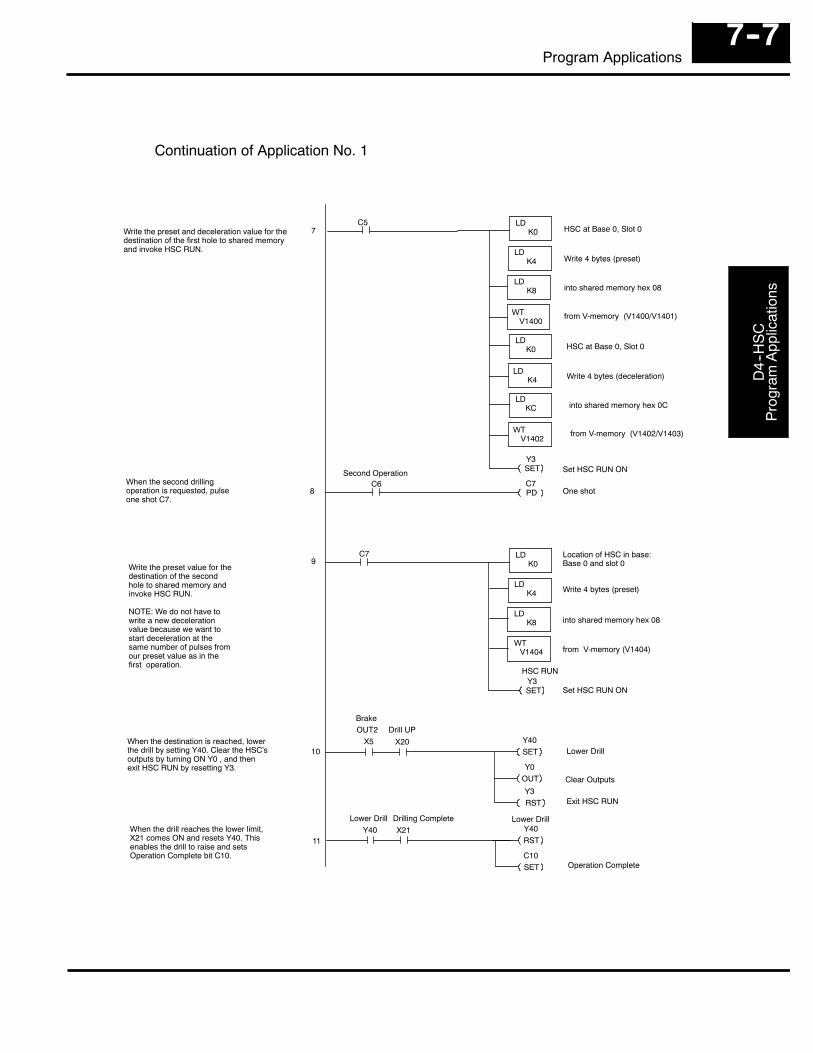
D4-
-HS
CP
rogr
amA
pplic
atio
ns
7--7Program Applications
C5
K4
WT
LDK8
V1400
LDK0
LD
HSC at Base 0, Slot 0
LD
LDK0
K4
Y3SET
C7
Set HSC RUN ON
One shot
Location of HSC in base:Base 0 and slot 0
Write 4 bytes (preset)
into shared memory hex 08
Lower Drill
Clear Outputs
Lower Drill
Operation Complete
into shared memory hex 08
Write 4 bytes (preset)
from V-memory (V1400/V1401)
7
8
WT
LDKC
V1402
C7PD
C6
K4
LDK8
LDK0
LD
Y3SET
Y40SET
X5 X20
Y0OUT
OUT2 Drill UP
Y40RST
Y40 X21
C10SET
Lower Drill Drilling Complete
from V-memory (V1404)WT
V1404
HSC RUN
When the destination is reached, lowerthe drill by setting Y40. Clear the HSC’soutputs by turning ON Y0 , and thenexit HSC RUN by resetting Y3.
Write the preset value for thedestination of the secondhole to shared memory andinvoke HSC RUN.
NOTE: We do not have towrite a new decelerationvalue because we want tostart deceleration at thesame number of pulses fromour preset value as in thefirst operation.
When the second drillingoperation is requested, pulseone shot C7.
Write the preset and deceleration value for thedestination of the first hole to shared memoryand invoke HSC RUN.
9
10
11
HSC at Base 0, Slot 0
Write 4 bytes (deceleration)
into shared memory hex 0C
from V-memory (V1402/V1403)
Second Operation
Continuation of Application No. 1
Set HSC RUN ON
Brake
Y3RST Exit HSC RUN
When the drill reaches the lower limit,X21 comes ON and resets Y40. Thisenables the drill to raise and setsOperation Complete bit C10.
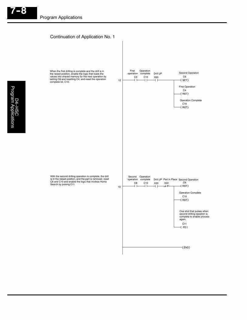
D4--H
SC
Program
Applications
7--8Program Applications
13
First Operation
C3 C10 C6SET12
C4RST
C10RST
X20
Firstoperation
Operationcomplete Drill UP Second Operation
Operation Complete
Second Operation
Operation Complete
C6RST
C6 C10
C10RST
C11PD
X20
Secondoperation
Operationcomplete Drill UP
When the first drilling is complete and the drill is inthe raised position, enable the logic that loads thevalues into shared memory for the next operation bysetting C6 and resetting C4, and reset the operationcomplete bit, C10.
With the second drilling operation is complete, the drillis in the raised position, and the part is removed, resetC6 and C10 and enable the logic that invokes HomeSearch by pulsing C11.
END
Continuation of Application No. 1
X22Part in Place
One shot that pulses whensecond drilling opeation iscomplete to enable processagain.
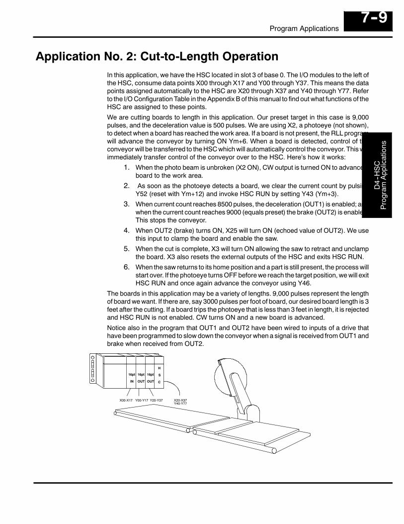
D4-
-HS
CP
rogr
amA
pplic
atio
ns
7--9Program Applications
Application No. 2: Cut-to-Length OperationIn this application, we have the HSC located in slot 3 of base 0. The I/O modules to the left ofthe HSC, consume data points X00 through X17 and Y00 through Y37. This means the datapoints assigned automatically to the HSC are X20 through X37 and Y40 through Y77. Referto the I/O Configuration Table in the Appendix B of this manual to find out what functions of theHSC are assigned to these points.
We are cutting boards to length in this application. Our preset target in this case is 9,000pulses, and the deceleration value is 500 pulses. We are using X2, a photoeye (not shown),to detect when a board has reached the work area. If a board is not present, the RLL programwill advance the conveyor by turning ON Ym+6. When a board is detected, control of theconveyor will be transferred to the HSC which will automatically control the conveyor. This willimmediately transfer control of the conveyor over to the HSC. Here’s how it works:
1. When the photo beam is unbroken (X2 ON), CW output is turned ON to advance aboard to the work area.
2. As soon as the photoeye detects a board, we clear the current count by pulsingY52 (reset with Ym+12) and invoke HSC RUN by setting Y43 (Ym+3).
3. When current count reaches 8500 pulses, the deceleration (OUT1) is enabled; andwhen the current count reaches 9000 (equals preset) the brake (OUT2) is enabled.This stops the conveyor.
4. When OUT2 (brake) turns ON, X25 will turn ON (echoed value of OUT2). We usethis input to clamp the board and enable the saw.
5. When the cut is complete, X3 will turn ON allowing the saw to retract and unclampthe board. X3 also resets the external outputs of the HSC and exits HSC RUN.
6. When the saw returns to its home position and a part is still present, the process willstart over. If the photoeye turns OFF before we reach the target position, we will exitHSC RUN and once again advance the conveyor using Y46.
The boards in this application may be a variety of lengths. 9,000 pulses represent the lengthof board we want. If there are, say 3000 pulses per foot of board, our desired board length is 3feet after the cutting. If a board trips the photoeye that is less than 3 feet in length, it is rejectedand HSC RUN is not enabled. CW turns ON and a new board is advanced.
Notice also in the program that OUT1 and OUT2 have been wired to inputs of a drive thathave been programmed to slow down the conveyor when a signal is received from OUT1 andbrake when received from OUT2.
IN OUT OUT
H
S
C
X00-X17 Y00-Y17 Y20-Y37 X20-X37Y40-Y77
16pt 16pt 16pt
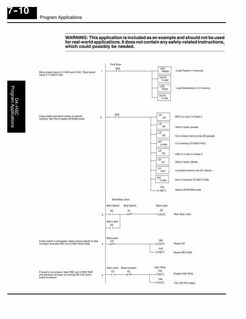
D4--H
SC
Program
Applications
7--10Program Applications
WARNING: This application is included as an example and should not be usedfor real-world applications. It does not containany safety-related instructions,which could possibly be needed.
SP0
SP0
K4
WT
LDK8
V1400
LDK3
LD
1
2
4
5
3
Y53SET
C0
OUT
X1X0
C0
Load Preset in V-memory
Write 4 bytes (preset)
from shared memory hex 08 (preset)
to V-memory (V1400/V1401)
HSC is in slot 3 of base 0
V1400
OUTD
LDDK500
V1402
LDDK9000
OUTD
Load Deceleration in V-memory
First Scan
K4
WT
LDK0C
V1402
LDK3
LD
Reset HSC RUN
Y63OUT
C0
Y43RST
HSC RUN
Turn ON CW output
Y43RST
C0 X2
Y46OUT
Start Latch Board present
Enable HSC RUN
Reset CW
Start LatchStop SwitchStart Switch
Start Stop Latch
HSC is in slot 3 of base 0
Write 4 bytes (decel)..
to shared memory hex 0C (decel)...
from V-memory (V1402/V1403)
Select UP/DOWN mode
Store preset value in V1400 and V1401. Store decelvalue in V1402/V1403
Copy preset and decel values to sharedmemory. Set Y53 to select UP/DWN mode
Start Latch
Start/Stop Latch
If stop switch is energized, reset control outputs to stopconveyor and take HSC out of HSC RUN mode.
If board is not present, take HSC out of HSC RUNand advance conveyor by turning ON Y46 until aboard is present.
Start Latch
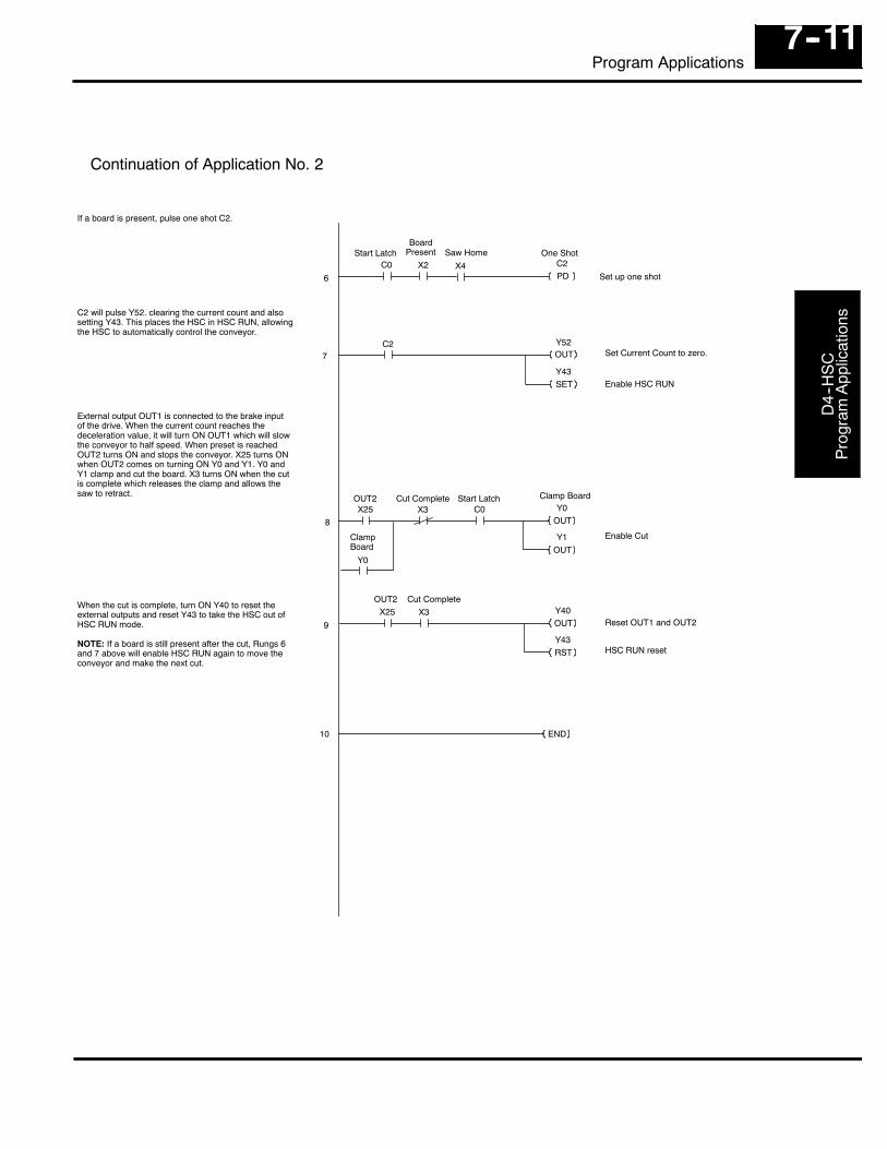
D4-
-HS
CP
rogr
amA
pplic
atio
ns
7--11Program Applications
Set Current Count to zero.
Set up one shot6
7
8
9 Reset OUT1 and OUT2
Continuation of Application No. 2
One ShotC2PD
C0 X2 X4
BoardPresent Saw Home
Enable HSC RUN
Y52OUT
C2
Y43SET
Y0OUT
X25 X3
Y1OUT
OUT2 Cut Complete
Y0
HSC RUN reset
Y40X25 X3
Y43RST
OUT2 Cut Complete
OUT
END10
ClampBoard
Clamp Board
External output OUT1 is connected to the brake inputof the drive. When the current count reaches thedeceleration value, it will turn ON OUT1 which will slowthe conveyor to half speed. When preset is reachedOUT2 turns ON and stops the conveyor. X25 turns ONwhen OUT2 comes on turning ON Y0 and Y1. Y0 andY1 clamp and cut the board. X3 turns ON when the cutis complete which releases the clamp and allows thesaw to retract.
C2 will pulse Y52. clearing the current count and alsosetting Y43. This places the HSC in HSC RUN, allowingthe HSC to automatically control the conveyor.
If a board is present, pulse one shot C2.
Enable Cut
C0Start Latch
Start Latch
When the cut is complete, turn ON Y40 to reset theexternal outputs and reset Y43 to take the HSC out ofHSC RUN mode.
NOTE: If a board is still present after the cut, Rungs 6and 7 above will enable HSC RUN again to move theconveyor and make the next cut.
1AIntroduction to MotorDrives and Encoders
In This Chapter. . . .— What is a Drive and How Does it Connect to the HSC— What is an Encoder and How Does it Connect to the HSC
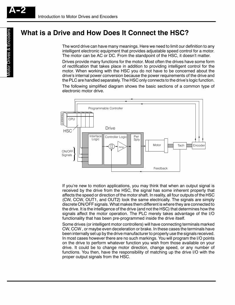
Intro
duct
ion
toM
otor
Driv
es&
Enc
oder
s
Introduction to Motor Drives and EncodersA--2
What is a Drive and How Does It Connect the HSC?
The word drive can have many meanings. Here we need to limit our definition to anyintelligent electronic equipment that provides adjustable speed control for a motor.The motor can be AC or DC. From the standpoint of the HSC, it doesn’t matter.Drives provide many functions for the motor. Most often the drives have some formof rectification that takes place in addition to providing intelligent control for themotor. When working with the HSC you do not have to be concerned about thedrive’s internal power conversion because the power requirements of the drive andthe PLC are handled separately. The HSC only connects to the drive’s logic function.The following simplified diagram shows the basic sections of a common type ofelectronic motor drive.
Programmable Controller
EncoderTachMotor
Controller LogicInterfaceLogic
Drive
PwrSply
Feedback
Amp
ON/OFFSignals
S
HSC
CPU
If you’re new to motion applications, you may think that when an output signal isreceived by the drive from the HSC, the signal has some inherent property thataffects the speed or direction of the motor shaft. In reality, all four outputs of the HSC(CW, CCW, OUT1, and OUT2) look the same electrically. The signals are simplydiscrete ON/OFF signals. What makes them different is where they are connected tothe drive. It is the intelligence of the drive (and not the HSC) that determines how thesignals affect the motor operation. The PLC merely takes advantage of the I/Ofunctionality that has been pre-programmed inside the drive itself.Some drives (or intelligent motor controllers) will have connecting terminals markedCW, CCW , or maybe even deceleration or brake. In these cases the terminals havebeen internally set up by the drive manufacturer to properly use the signals received.In most cases however there are no such markings. You will program the I/O pointson the drive to perform whatever function you wish from those available on yourdrive. It could be to change motor direction, change speed, or any number offunctions. You then, have the responsibility of matching up the drive I/O with theproper output signals from the HSC.
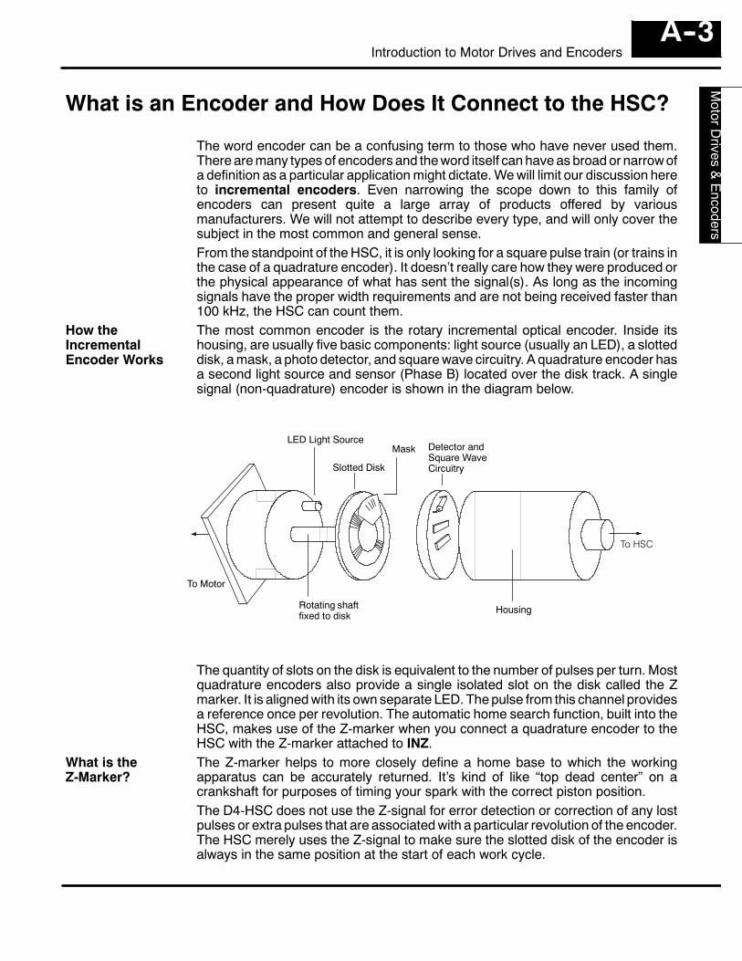
Introductionto
MotorD
rives&
Encoders
A--3Introduction to Motor Drives and Encoders
What is an Encoder and How Does It Connect to the HSC?
The word encoder can be a confusing term to those who have never used them.There are many types of encoders and the word itself can have as broad or narrow ofa definition as a particular application might dictate. We will limit our discussion hereto incremental encoders. Even narrowing the scope down to this family ofencoders can present quite a large array of products offered by variousmanufacturers. We will not attempt to describe every type, and will only cover thesubject in the most common and general sense.From the standpoint of the HSC, it is only looking for a square pulse train (or trains inthe case of a quadrature encoder). It doesn’t really care how they were produced orthe physical appearance of what has sent the signal(s). As long as the incomingsignals have the proper width requirements and are not being received faster than100 kHz, the HSC can count them.The most common encoder is the rotary incremental optical encoder. Inside itshousing, are usually five basic components: light source (usually an LED), a slotteddisk, a mask, a photo detector, and square wave circuitry. A quadrature encoder hasa second light source and sensor (Phase B) located over the disk track. A singlesignal (non-quadrature) encoder is shown in the diagram below.
LED Light Source
Slotted Disk
Mask Detector andSquare WaveCircuitry
Rotating shaftfixed to disk
Housing
To HSC
To Motor
The quantity of slots on the disk is equivalent to the number of pulses per turn. Mostquadrature encoders also provide a single isolated slot on the disk called the Zmarker. It is aligned with its own separate LED. The pulse from this channel providesa reference once per revolution. The automatic home search function, built into theHSC, makes use of the Z-marker when you connect a quadrature encoder to theHSC with the Z-marker attached to INZ.The Z-marker helps to more closely define a home base to which the workingapparatus can be accurately returned. It’s kind of like “top dead center” on acrankshaft for purposes of timing your spark with the correct piston position.The D4-HSC does not use the Z-signal for error detection or correction of any lostpulses or extra pulses that are associated with a particular revolution of the encoder.The HSC merely uses the Z-signal to make sure the slotted disk of the encoder isalways in the same position at the start of each work cycle.
How theIncrementalEncoder Works
What is theZ-Marker?
1BSummary of Tablesand Charts Presentedin the Text
In This Chapter. . . .— Specifications for D4-HSC— X and Y Assignment Table— Shared Memory Table— Table for Determining Count Direction— Counting Resolution Table (Quadrature Only)
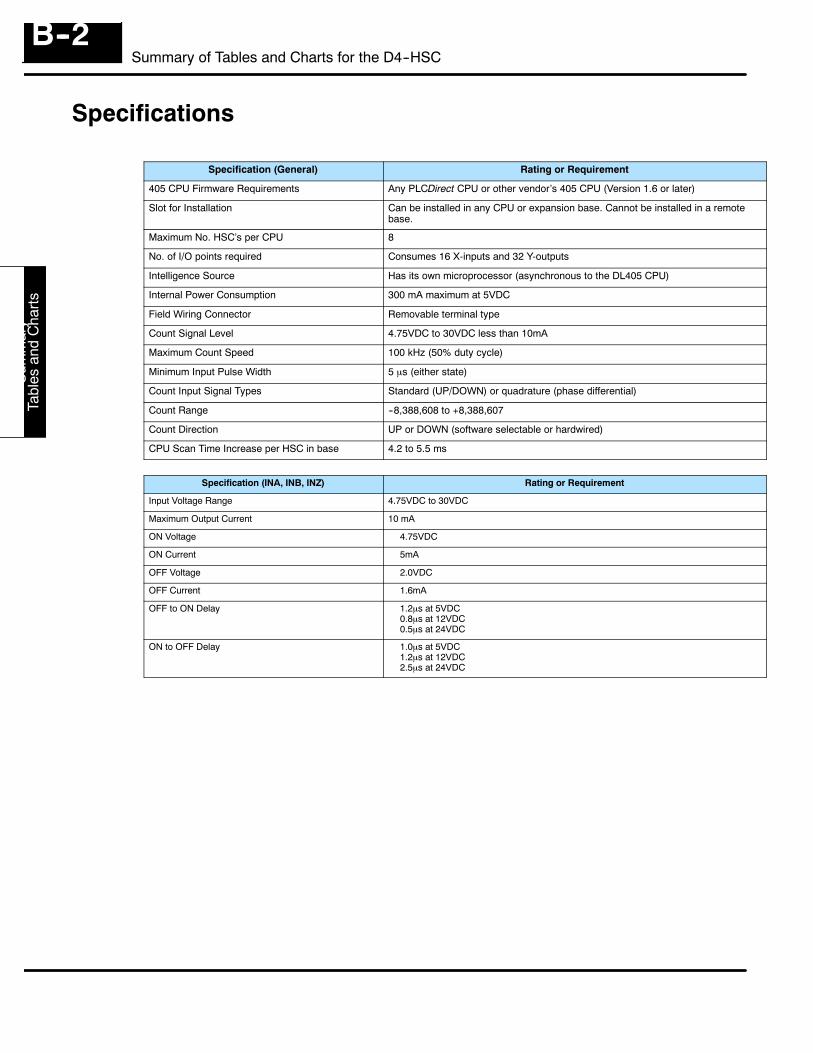
Sum
mar
yTa
bles
and
Cha
rts
Summary of Tables and Charts for the D4--HSCB--2
Specifications
Specification (General) Rating or Requirement
405 CPU Firmware Requirements Any PLCDirect CPU or other vendor’s 405 CPU (Version 1.6 or later)
Slot for Installation Can be installed in any CPU or expansion base. Cannot be installed in a remotebase.
Maximum No. HSC’s per CPU 8
No. of I/O points required Consumes 16 X-inputs and 32 Y-outputs
Intelligence Source Has its own microprocessor (asynchronous to the DL405 CPU)
Internal Power Consumption 300 mA maximum at 5VDC
Field Wiring Connector Removable terminal type
Count Signal Level 4.75VDC to 30VDC less than 10mA
Maximum Count Speed 100 kHz (50% duty cycle)
Minimum Input Pulse Width 5 µs (either state)
Count Input Signal Types Standard (UP/DOWN) or quadrature (phase differential)
Count Range --8,388,608 to +8,388,607
Count Direction UP or DOWN (software selectable or hardwired)
CPU Scan Time Increase per HSC in base 4.2 to 5.5 ms
Specification (INA, INB, INZ) Rating or Requirement
Input Voltage Range 4.75VDC to 30VDC
Maximum Output Current 10 mA
ON Voltage = 4.75VDC
ON Current = 5mA
OFF Voltage = 2.0VDC
OFF Current = 1.6mA
OFF to ON Delay = 1.2µs at 5VDC= 0.8µs at 12VDC= 0.5µs at 24VDC
ON to OFF Delay = 1.0µs at 5VDC= 1.2µs at 12VDC= 2.5µs at 24VDC
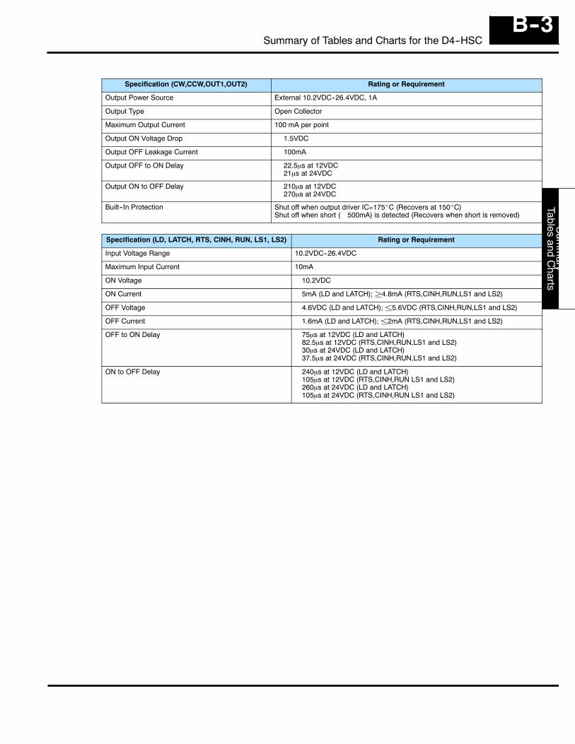
Sum
mary
Tablesand
Charts
B--3Summary of Tables and Charts for the D4--HSC
Specification (CW,CCW,OUT1,OUT2) Rating or Requirement
Output Power Source External 10.2VDC--26.4VDC, 1A
Output Type Open Collector
Maximum Output Current 100 mA per point
Output ON Voltage Drop = 1.5VDC
Output OFF Leakage Current = 100mA
Output OFF to ON Delay = 22.5µs at 12VDC= 21µs at 24VDC
Output ON to OFF Delay = 210µs at 12VDC= 270µs at 24VDC
Built--In Protection Shut off when output driver IC=175_C (Recovers at 150_C)Shut off when short (>500mA) is detected (Recovers when short is removed)
Specification (LD, LATCH, RTS, CINH, RUN, LS1, LS2) Rating or Requirement
Input Voltage Range 10.2VDC--26.4VDC
Maximum Input Current 10mA
ON Voltage =10.2VDC
ON Current =5mA (LD and LATCH); ²4.8mA (RTS,CINH,RUN,LS1 and LS2)
OFF Voltage =4.6VDC (LD and LATCH); ±5.6VDC (RTS,CINH,RUN,LS1 and LS2)
OFF Current =1.6mA (LD and LATCH); ±2mA (RTS,CINH,RUN,LS1 and LS2)
OFF to ON Delay =75µs at 12VDC (LD and LATCH)=82.5µs at 12VDC (RTS,CINH,RUN,LS1 and LS2)=30µs at 24VDC (LD and LATCH)=37.5µs at 24VDC (RTS,CINH,RUN,LS1 and LS2)
ON to OFF Delay =240µs at 12VDC (LD and LATCH)=105µs at 12VDC (RTS,CINH,RUN LS1 and LS2)=260µs at 24VDC (LD and LATCH)=105µs at 24VDC (RTS,CINH,RUN LS1 and LS2)
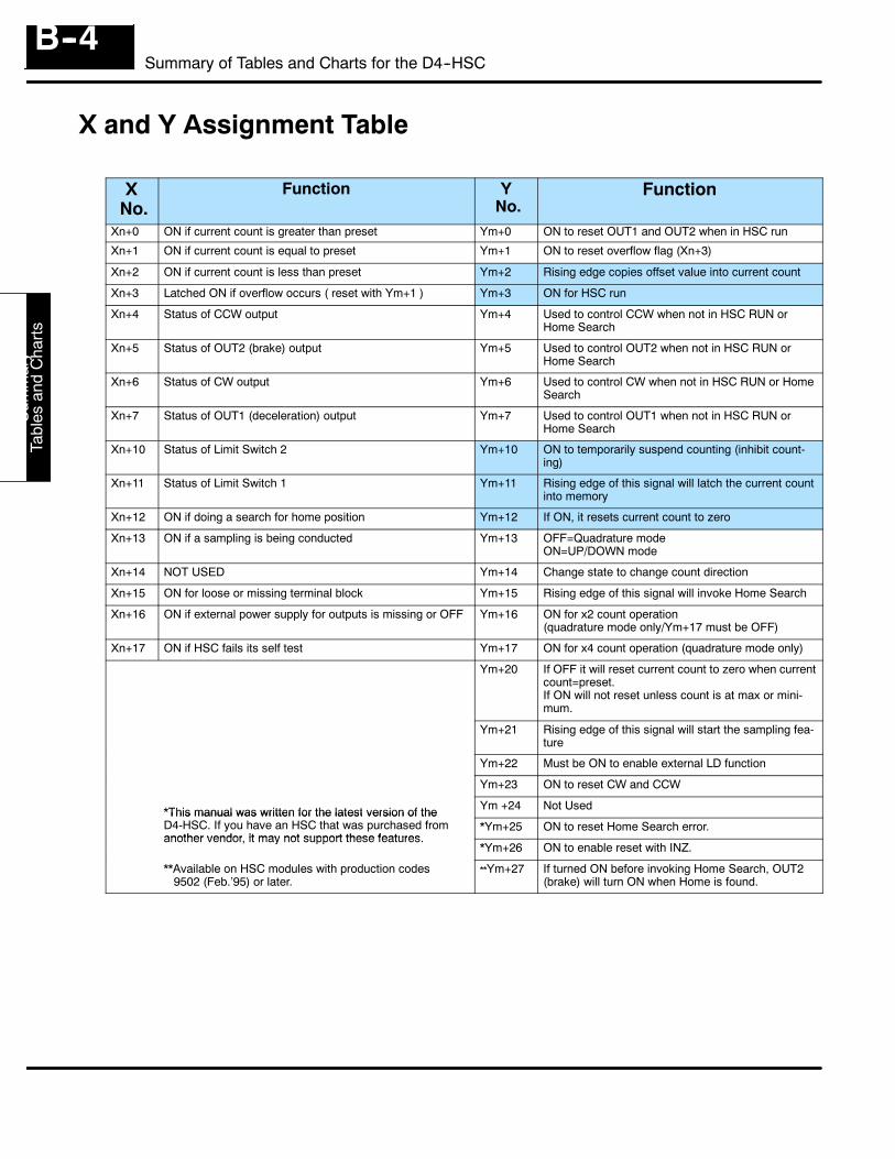
Sum
mar
yTa
bles
and
Cha
rts
Summary of Tables and Charts for the D4--HSCB--4
X and Y Assignment Table
XNo.
Function YNo.
Function
Xn+0 ON if current count is greater than preset Ym+0 ON to reset OUT1 and OUT2 when in HSC run
Xn+1 ON if current count is equal to preset Ym+1 ON to reset overflow flag (Xn+3)
Xn+2 ON if current count is less than preset Ym+2 Rising edge copies offset value into current count
Xn+3 Latched ON if overflow occurs ( reset with Ym+1 ) Ym+3 ON for HSC run
Xn+4 Status of CCW output Ym+4 Used to control CCW when not in HSC RUN orHome Search
Xn+5 Status of OUT2 (brake) output Ym+5 Used to control OUT2 when not in HSC RUN orHome Search
Xn+6 Status of CW output Ym+6 Used to control CW when not in HSC RUN or HomeSearch
Xn+7 Status of OUT1 (deceleration) output Ym+7 Used to control OUT1 when not in HSC RUN orHome Search
Xn+10 Status of Limit Switch 2 Ym+10 ON to temporarily suspend counting (inhibit count-ing)
Xn+11 Status of Limit Switch 1 Ym+11 Rising edge of this signal will latch the current countinto memory
Xn+12 ON if doing a search for home position Ym+12 If ON, it resets current count to zero
Xn+13 ON if a sampling is being conducted Ym+13 OFF=Quadrature modeON=UP/DOWN mode
Xn+14 NOT USED Ym+14 Change state to change count direction
Xn+15 ON for loose or missing terminal block Ym+15 Rising edge of this signal will invoke Home Search
Xn+16 ON if external power supply for outputs is missing or OFF Ym+16 ON for x2 count operation(quadrature mode only/Ym+17 must be OFF)
Xn+17 ON if HSC fails its self test Ym+17 ON for x4 count operation (quadrature mode only)
Ym+20 If OFF it will reset current count to zero when currentcount=preset.If ON will not reset unless count is at max or mini-mum.
Ym+21 Rising edge of this signal will start the sampling fea-ture
Ym+22 Must be ON to enable external LD function
Ym+23 ON to reset CW and CCW
*This manual was written for the latest version of the Ym +24 Not Used*This manual was written for the latest version of theD4-HSC. If you have an HSC that was purchased fromanother vendor, it may not support these features.
*Ym+25 ON to reset Home Search error.another vendor, it may not support these features.
*Ym+26 ON to enable reset with INZ.
**Available on HSC modules with production codes9502 (Feb.’95) or later.
**Ym+27 If turned ON before invoking Home Search, OUT2(brake) will turn ON when Home is found.
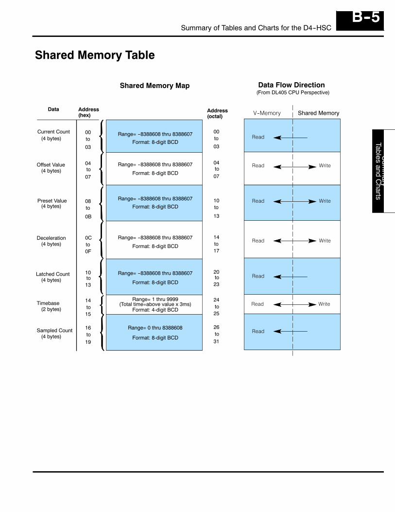
Sum
mary
Tablesand
Charts
B--5Summary of Tables and Charts for the D4--HSC
Shared Memory Table
Current Count
Offset Value
Preset Value
Deceleration
Latched Count
Sampled Count
Timebase
Shared Memory Map Data Flow Direction
Read
Read Write
Read
Read
Read Write
Read Write
Read Write
Address(hex)
Data
00
04
08
0C
10
14
16
(4 bytes)
(4 bytes)
(4 bytes)
(4 bytes)
(4 bytes)
(4 bytes)
(2 bytes)
Range= --8388608 thru 8388607
Range= --8388608 thru 8388607
Range= --8388608 thru 8388607
Range= --8388608 thru 8388607
Range= --8388608 thru 8388607
Range= 0 thru 8388608
Format: 8-digit BCD
Range= 1 thru 9999
Format: 8-digit BCD
Format: 8-digit BCD
Format: 8-digit BCD
Format: 8-digit BCD
Format: 8-digit BCD
Format: 4-digit BCD(Total time=above value x 3ms)
V--Memory Shared Memory
(From DL405 CPU Perspective)
to03
to07
to
0B
to0F
to13
to15
to19
Address(octal)
00
04
10
14
20
24
26
to03
to07
to
13
to17
to23
to25
to31
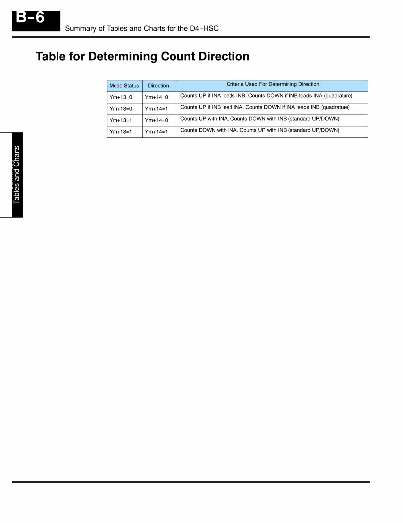
Sum
mar
yTa
bles
and
Cha
rts
Summary of Tables and Charts for the D4--HSCB--6
Table for Determining Count Direction
Mode Status Direction Criteria Used For Determining Direction
Ym+13=0 Ym+14=0 Counts UP if INA leads INB. Counts DOWN if INB leads INA (quadrature)
Ym+13=0 Ym+14=1 Counts UP if INB lead INA. Counts DOWN if INA leads INB (quadrature)
Ym+13=1 Ym+14=0 Counts UP with INA. Counts DOWN with INB (standard UP/DOWN)
Ym+13=1 Ym+14=1 Counts DOWN with INA. Counts UP with INB (standard UP/DOWN)
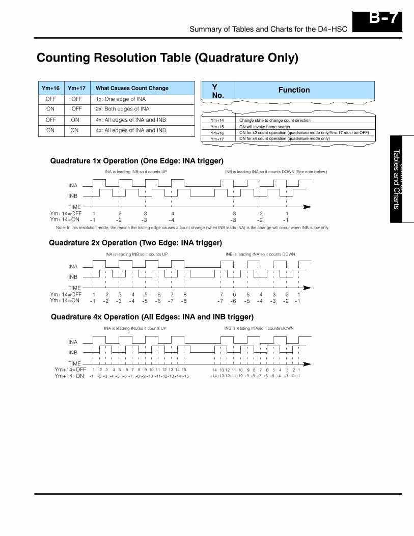
Sum
mary
Tablesand
Charts
B--7Summary of Tables and Charts for the D4--HSC
Counting Resolution Table (Quadrature Only)
FunctionYNo.
Ym+14
Ym+15
Ym+16
Change state to change count direction
ON will invoke home searchON for x2 count operation (quadrature mode only/Ym+17 must be OFF)
Ym+17 ON for x4 count operation (quadrature mode only)
Ym+16 Ym+17
OFFOFF
OFFON
ONOFF
ONON
What Causes Count Change
1x: One edge of INA
2x: Both edges of INA
4x: All edges of INA and INB
4x: All edges of INA and INB
Quadrature 1x Operation (One Edge: INA trigger)
Quadrature 2x Operation (Two Edge: INA trigger)
Quadrature 4x Operation (All Edges: INA and INB trigger)
1 2 3 4 3 2 1--1 --2 --3 --4 --3 --2 --1
INA
INB
TIMEYm+14=OFFYm+14=ON
1 2 3 4 6 4 2--1 --2 --3 --4 --6 --4 --2
INA
INB
TIMEYm+14=OFFYm+14=ON
INA
INB
TIMEYm+14=OFFYm+14=ON
5 6 7 8--5 --6 --7 --8
7 5 3--7 --5 --3
1--1
1 3 5 7
--1 --3 --5 --7
9 11 13 15
--9 --11 --13 --15
2 4 6
--2 --4 --6
8 10 12 14
--8 --10 --12 --1414 13 12 11 10 9 8 7 6 5 4 3 12
--14 --13--12--11--10 --9 --8 --7 --6 --5 --4 --3 --2 --1
INA is leading INB;so it counts UP INB is leading INA;so it counts DOWN (See note below.)
INA is leading INB;so it counts UP INB is leading INA;so it counts DOWN
INA is leading INB;so it counts UP INB is leading INA;so it counts DOWN
Note: In this resolution mode, the reason the trailing edge causes a count change (when INB leads INA) is the change will occur when INB is low only.
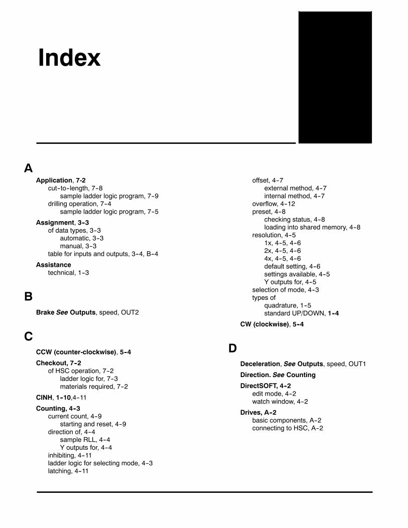
1Index
AApplication, 7-2
cut--to--length, 7--8sample ladder logic program, 7--9
drilling operation, 7--4sample ladder logic program, 7--5
Assignment, 3--3of data types, 3--3
automatic, 3--3manual, 3--3
table for inputs and outputs, 3--4, B--4
Assistancetechnical, 1--3
BBrake See Outputs, speed, OUT2
CCCW (counter-clockwise), 5--4
Checkout, 7--2of HSC operation, 7--2
ladder logic for, 7--3materials required, 7--2
CINH, 1--10,4--11
Counting, 4--3current count, 4--9
starting and reset, 4--9direction of, 4--4
sample RLL, 4--4Y outputs for, 4--4
inhibiting, 4--11ladder logic for selecting mode, 4--3latching, 4--11
offset, 4--7external method, 4--7internal method, 4--7
overflow, 4--12preset, 4--8
checking status, 4--8loading into shared memory, 4--8
resolution, 4--51x, 4--5, 4--62x, 4--5, 4--64x, 4--5, 4--6default setting, 4--6settings available, 4--5Y outputs for, 4--5
selection of mode, 4--3types of
quadrature, 1--5standard UP/DOWN, 1--4
CW (clockwise), 5--4
DDeceleration, See Outputs, speed, OUT1
Direction. See Counting
DirectSOFT, 4--2edit mode, 4--2watch window, 4--2
Drives, A--2basic components, A--2connecting to HSC, A--2
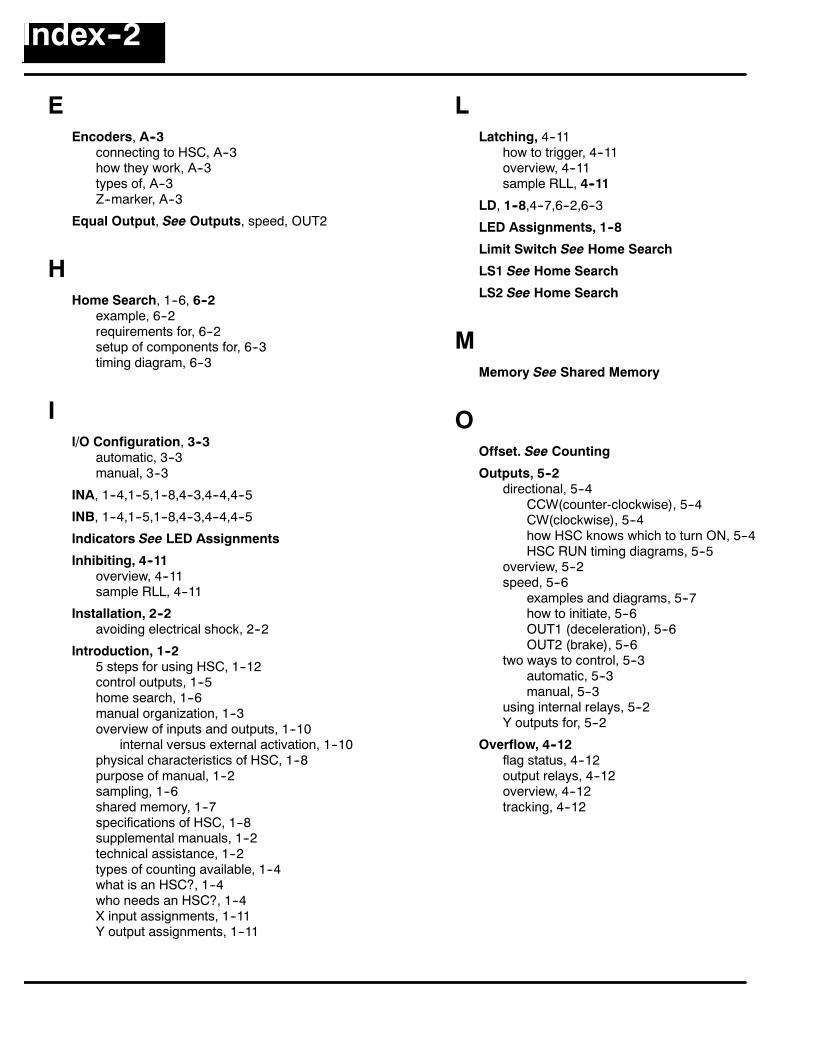
Index--2
EEncoders, A--3
connecting to HSC, A--3how they work, A--3types of, A--3Z--marker, A--3
Equal Output, See Outputs, speed, OUT2
HHome Search, 1--6, 6--2
example, 6--2requirements for, 6--2setup of components for, 6--3timing diagram, 6--3
II/O Configuration, 3--3
automatic, 3--3manual, 3--3
INA, 1--4,1--5,1--8,4--3,4--4,4--5
INB, 1--4,1--5,1--8,4--3,4--4,4--5
Indicators See LED Assignments
Inhibiting, 4--11overview, 4--11sample RLL, 4--11
Installation, 2--2avoiding electrical shock, 2--2
Introduction, 1--25 steps for using HSC, 1--12control outputs, 1--5home search, 1--6manual organization, 1--3overview of inputs and outputs, 1--10
internal versus external activation, 1--10physical characteristics of HSC, 1--8purpose of manual, 1--2sampling, 1--6shared memory, 1--7specifications of HSC, 1--8supplemental manuals, 1--2technical assistance, 1--2types of counting available, 1--4what is an HSC?, 1--4who needs an HSC?, 1--4X input assignments, 1--11Y output assignments, 1--11
LLatching, 4--11
how to trigger, 4--11overview, 4--11sample RLL, 4--11
LD, 1--8,4--7,6--2,6--3
LED Assignments, 1--8
Limit Switch See Home Search
LS1 See Home Search
LS2 See Home Search
MMemory See Shared Memory
OOffset. See Counting
Outputs, 5--2directional, 5--4
CCW(counter-clockwise), 5--4CW(clockwise), 5--4how HSC knows which to turn ON, 5--4HSC RUN timing diagrams, 5--5
overview, 5--2speed, 5--6
examples and diagrams, 5--7how to initiate, 5--6OUT1 (deceleration), 5--6OUT2 (brake), 5--6
two ways to control, 5--3automatic, 5--3manual, 5--3
using internal relays, 5--2Y outputs for, 5--2
Overflow, 4--12flag status, 4--12output relays, 4--12overview, 4--12tracking, 4--12
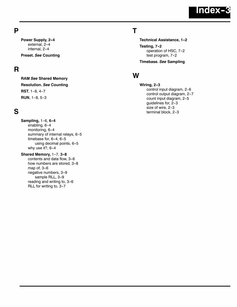
Index--3
PPower Supply, 2--4
external, 2--4internal, 2--4
Preset. See Counting
RRAM See Shared Memory
Resolution. See Counting
RST, 1--8, 4--7
RUN, 1--8, 5--3
SSampling, 1--6, 6--4
enabling, 6--4monitoring, 6--4summary of internal relays, 6--5timebase for, 6--4, 6--5
using decimal points, 6--5why use it?, 6--4
Shared Memory, 1--7, 3--8contents and data flow, 3--6how numbers are stored, 3--8map of, 3--6negative numbers, 3--9
sample RLL, 3--9reading and writing to, 3--6RLL for writing to, 3--7
TTechnical Assistance, 1--2
Testing, 7--2operation of HSC, 7--2test program, 7--2
Timebase. See Sampling
WWiring, 2--3
control input diagram, 2--6control output diagram, 2--7count input diagram, 2--5guidelines for, 2--3size of wire, 2--3terminal block, 2--3