Embed Size (px)
DESCRIPTION
Electricity
Citation preview
AUTOMATION STRATEGY FEED MHPP Mamasa
AUTOMATION STRATEGY OFMHPP Mamasa
1 Introduction of Automation SystemsHydropower stations are mainly located in remote mountainous area and far from town,
which use computer monitoring and control system instead of manual operation and timing
tour of inspection and record etc miscellaneous labor to realize the unattended or less
unattended.
Integrated automation of hydropower station is a full automatic monitoring control system
and based on the basis of computer monitoring and control system, which is used for the
hydrological measuring and reporting the whole hydropower plant, even the cascade
hydropower stations or the entire river basin(including start-stop control and operating
condition monitoring of the Unit, auxiliary and utility equipments, load distribution), until
the automatic control of transmission line in the whole operation process, and is able to
accurate and real-time data communicate etc with the scheduling department at the next
higher level. Generally it includes five subsystems.
SCADA (supervisory control and data acquisition) is a system that operates with coded
signals over communication channels so as to provide control of remote equipment (using
typically one communication channel per remote station). The control system may be
combined with a data acquisition system by adding the use of coded signals over
communication channels to acquire information about the status of the remote equipment
for display or for recording functions. SCADA systems are used to monitor all the parameters
of the power plant and its supporting tools. In principle, SCADA systems are used to
maintain the rotation of the turbine so that all the electrical parameters of both voltage and
frequency can be maintained. Rotation of the turbine is set by adjusting the governor means
regulate the amount of water into the turbine. Besides other parameters that must be
observed by the SCADA is vibration and temperature of the turbine itself.
In general, this SCADA system controls has 3 main part:
1 | P a g e
AUTOMATION STRATEGY FEED MHPP Mamasa
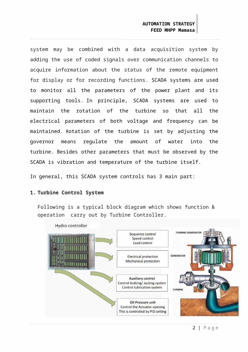
1. Turbine Control System
Following is a typical block diagram which shows function & operation carry out by Turbine Controller.
Speed & load control.
Turbine Controller has state of art measuring & controlling function for speed regulation, load measurement & control.Turbine Controller has special feature of “Energy measurement” for speed regulation. In Energy measurement the Turbine Controller not only monitors the rotational speed but also monitors the acceleration & deceleration part for regulation during ramping up & down of turbine.
Sequence Control.Once start command is given to controller (by a Digital input or through touch panel or by Modbus command), controller will give necessary commands (to OPU system, to LUB plant, to CW system & all other auxiliaries if present) to carry out the sequencing operation, Brake control operation is also been taken care by controller during starting & stopping sequence. Once all preset conditions are met to rotate turbine, controller will take the machine to rated RPM.
Synchronization & load control
Once reached to Rated RPM in Auto mode, controller will start synchronization &
once all the condition are met, controller will close the generator breaker &
2 | P a g e
AUTOMATION STRATEGY FEED MHPP Mamasa
regulate the machine to given power set point. This power set point can be changed
either by Touch panel, or by Analog input or by Modbus command.
Mechanical Protection
All the RTD connected to Turbine Controller are measured continuously & once
Temperature rises above given set point Turbine Controller will give suitable alarm or
Trip. Text & protection set points for RTD are freely configurable from Touch Panel & can
be changed easily.
Electrical Protection
Turbine Controller is built in protection unit in it. It measures the voltage (of generator &
mains) & current of generator & carry out the necessary protections. All the set points &
time delay for protection function can be changed by Touch panel.
2. LV and MV Control System
Relay protection at low voltage (LV)& Medium voltage (MV) panel is used to limit the
existing electrical parameters. Protection relays have two values, namely limit values
and alarm trip value. If the parameters are detected has reached the value of the alarm,
the alarm will sound and the system operator take steps to eliminate the alarm, if it can
not reached the nominal value then the parameter will rise to reach the rip level. If the
trip level is reached then the circuit breaker open to disconnect between the system and
the load. It is used to secure the load / customers from excess voltage.
3. Auxiliary Control system
Auxiliary control system is a support system so that all systems can work well. In
addition to oil cooling system for the turbine, some sensors are also used for detecting
parameters to be detected. Parameters like vibration is also necessary to keep the
turbine has been working without any interruption of the mechanical side. There was
also a sensor to determine the water pressure in the penstock pipe.
3 | P a g e
AUTOMATION STRATEGY FEED MHPP Mamasa
The water pressure is needed to determine whether the pressures of water is sufficient
to run a turbine or not.
4 | P a g e
AUTOMATION STRATEGY FEED MHPP Mamasa
5 | P a g e